WO2019044005A1 - プリンタ - Google Patents
プリンタ Download PDFInfo
- Publication number
- WO2019044005A1 WO2019044005A1 PCT/JP2018/009446 JP2018009446W WO2019044005A1 WO 2019044005 A1 WO2019044005 A1 WO 2019044005A1 JP 2018009446 W JP2018009446 W JP 2018009446W WO 2019044005 A1 WO2019044005 A1 WO 2019044005A1
- Authority
- WO
- WIPO (PCT)
- Prior art keywords
- printing
- head
- printer
- image
- Prior art date
- Legal status (The legal status is an assumption and is not a legal conclusion. Google has not performed a legal analysis and makes no representation as to the accuracy of the status listed.)
- Ceased
Links
Images











Classifications
-
- B—PERFORMING OPERATIONS; TRANSPORTING
- B41—PRINTING; LINING MACHINES; TYPEWRITERS; STAMPS
- B41J—TYPEWRITERS; SELECTIVE PRINTING MECHANISMS, i.e. MECHANISMS PRINTING OTHERWISE THAN FROM A FORME; CORRECTION OF TYPOGRAPHICAL ERRORS
- B41J3/00—Typewriters or selective printing or marking mechanisms characterised by the purpose for which they are constructed
- B41J3/28—Typewriters or selective printing or marking mechanisms characterised by the purpose for which they are constructed for printing downwardly on flat surfaces, e.g. of books, drawings, boxes, envelopes, e.g. flat-bed ink-jet printers
-
- B—PERFORMING OPERATIONS; TRANSPORTING
- B41—PRINTING; LINING MACHINES; TYPEWRITERS; STAMPS
- B41J—TYPEWRITERS; SELECTIVE PRINTING MECHANISMS, i.e. MECHANISMS PRINTING OTHERWISE THAN FROM A FORME; CORRECTION OF TYPOGRAPHICAL ERRORS
- B41J2/00—Typewriters or selective printing mechanisms characterised by the printing or marking process for which they are designed
- B41J2/005—Typewriters or selective printing mechanisms characterised by the printing or marking process for which they are designed characterised by bringing liquid or particles selectively into contact with a printing material
- B41J2/01—Ink jet
-
- B—PERFORMING OPERATIONS; TRANSPORTING
- B41—PRINTING; LINING MACHINES; TYPEWRITERS; STAMPS
- B41J—TYPEWRITERS; SELECTIVE PRINTING MECHANISMS, i.e. MECHANISMS PRINTING OTHERWISE THAN FROM A FORME; CORRECTION OF TYPOGRAPHICAL ERRORS
- B41J2/00—Typewriters or selective printing mechanisms characterised by the printing or marking process for which they are designed
- B41J2/005—Typewriters or selective printing mechanisms characterised by the printing or marking process for which they are designed characterised by bringing liquid or particles selectively into contact with a printing material
- B41J2/01—Ink jet
- B41J2/17—Ink jet characterised by ink handling
- B41J2/175—Ink supply systems ; Circuit parts therefor
-
- B—PERFORMING OPERATIONS; TRANSPORTING
- B41—PRINTING; LINING MACHINES; TYPEWRITERS; STAMPS
- B41J—TYPEWRITERS; SELECTIVE PRINTING MECHANISMS, i.e. MECHANISMS PRINTING OTHERWISE THAN FROM A FORME; CORRECTION OF TYPOGRAPHICAL ERRORS
- B41J21/00—Column, tabular or like printing arrangements; Means for centralising short lines
- B41J21/16—Column, tabular or like printing arrangements; Means for centralising short lines controlled by the sensing of marks or formations on the paper being typed, an undersheet, or the platen
-
- B—PERFORMING OPERATIONS; TRANSPORTING
- B41—PRINTING; LINING MACHINES; TYPEWRITERS; STAMPS
- B41J—TYPEWRITERS; SELECTIVE PRINTING MECHANISMS, i.e. MECHANISMS PRINTING OTHERWISE THAN FROM A FORME; CORRECTION OF TYPOGRAPHICAL ERRORS
- B41J25/00—Actions or mechanisms not otherwise provided for
- B41J25/304—Bodily-movable mechanisms for print heads or carriages movable towards or from paper surface
- B41J25/308—Bodily-movable mechanisms for print heads or carriages movable towards or from paper surface with print gap adjustment mechanisms
-
- B—PERFORMING OPERATIONS; TRANSPORTING
- B41—PRINTING; LINING MACHINES; TYPEWRITERS; STAMPS
- B41J—TYPEWRITERS; SELECTIVE PRINTING MECHANISMS, i.e. MECHANISMS PRINTING OTHERWISE THAN FROM A FORME; CORRECTION OF TYPOGRAPHICAL ERRORS
- B41J3/00—Typewriters or selective printing or marking mechanisms characterised by the purpose for which they are constructed
- B41J3/44—Typewriters or selective printing mechanisms having dual functions or combined with, or coupled to, apparatus performing other functions
-
- B—PERFORMING OPERATIONS; TRANSPORTING
- B64—AIRCRAFT; AVIATION; COSMONAUTICS
- B64U—UNMANNED AERIAL VEHICLES [UAV]; EQUIPMENT THEREFOR
- B64U10/00—Type of UAV
- B64U10/10—Rotorcrafts
- B64U10/13—Flying platforms
- B64U10/14—Flying platforms with four distinct rotor axes, e.g. quadcopters
-
- B—PERFORMING OPERATIONS; TRANSPORTING
- B41—PRINTING; LINING MACHINES; TYPEWRITERS; STAMPS
- B41J—TYPEWRITERS; SELECTIVE PRINTING MECHANISMS, i.e. MECHANISMS PRINTING OTHERWISE THAN FROM A FORME; CORRECTION OF TYPOGRAPHICAL ERRORS
- B41J3/00—Typewriters or selective printing or marking mechanisms characterised by the purpose for which they are constructed
- B41J3/44—Typewriters or selective printing mechanisms having dual functions or combined with, or coupled to, apparatus performing other functions
- B41J3/445—Printers integrated in other types of apparatus, e.g. printers integrated in cameras
-
- B—PERFORMING OPERATIONS; TRANSPORTING
- B64—AIRCRAFT; AVIATION; COSMONAUTICS
- B64U—UNMANNED AERIAL VEHICLES [UAV]; EQUIPMENT THEREFOR
- B64U2101/00—UAVs specially adapted for particular uses or applications
- B64U2101/25—UAVs specially adapted for particular uses or applications for manufacturing or servicing
- B64U2101/28—UAVs specially adapted for particular uses or applications for manufacturing or servicing for painting or marking
-
- B—PERFORMING OPERATIONS; TRANSPORTING
- B64—AIRCRAFT; AVIATION; COSMONAUTICS
- B64U—UNMANNED AERIAL VEHICLES [UAV]; EQUIPMENT THEREFOR
- B64U2101/00—UAVs specially adapted for particular uses or applications
- B64U2101/30—UAVs specially adapted for particular uses or applications for imaging, photography or videography
-
- B—PERFORMING OPERATIONS; TRANSPORTING
- B64—AIRCRAFT; AVIATION; COSMONAUTICS
- B64U—UNMANNED AERIAL VEHICLES [UAV]; EQUIPMENT THEREFOR
- B64U2201/00—UAVs characterised by their flight controls
- B64U2201/10—UAVs characterised by their flight controls autonomous, i.e. by navigating independently from ground or air stations, e.g. by using inertial navigation systems [INS]
-
- B—PERFORMING OPERATIONS; TRANSPORTING
- B64—AIRCRAFT; AVIATION; COSMONAUTICS
- B64U—UNMANNED AERIAL VEHICLES [UAV]; EQUIPMENT THEREFOR
- B64U2201/00—UAVs characterised by their flight controls
- B64U2201/20—Remote controls
Definitions
- the present invention relates to a printer having a print head mounted on an unmanned flying object called drone, and in particular, flying to approach a print target and forming a desired image in a non-contact state with the print target Is concerned with printers that can.
- the invention of a multicopter is disclosed in Patent Document 1 below.
- the multicopter 3 is provided with a vacuum suction unit 2 and a cleaning device 4 in a self-lifting structure 1 having a plurality of rotors 11.
- This multicopter has flight performance that can fly by itself automatically to reach the surface of the target position, move on the surface by itself, and move away from the surface.
- the printing apparatus 4 can be equipped instead of the cleaning apparatus 4.
- the printing apparatus 4 of the multicopter has a roller-like structure, and is considered to be an application roller which applies a paint in contact with an object. Therefore, this multicopter sucks with a suction device to the wall surface etc. of movement destination and brings the coating roller of the printing device into contact with the wall surface, drives the rotor in that state and moves along the wall surface while moving by the coating roller It is considered that printing is to be performed.
- Patent Document 1 since printing is performed in contact with the printing target surface, printing may be impossible or difficult depending on the condition of the printing target surface.
- it is a printing apparatus in which the application roller is mounted on the flying object, it is assumed that there are many cases where the printing operation is carried out by flying to a remote place or a place where access is usually difficult. Even if it turns out that the surface to be printed is not suitable for contact printing after reaching the condition (1), it may be considered that an appropriate response can not be taken.
- the image should be printed in a desired pattern, although it is possible to apply the paint to the planned rough shape. Was difficult.
- the present invention has been made in view of such prior art and its problems, and is a flightable printer having a printing apparatus mounted on a flying object, wherein the printing target surface reached by flight is not contacted.
- An object of the present invention is to provide a printer capable of printing a desired image.
- the printer described in claim 1 is With the flying body, A print head mounted on the flying object and printing a desired image contactlessly on a print target approaching the flying object; have.
- the flying object is caused to fly from the departure point to the vicinity of the print target, and the print head is driven in a non-contact state with respect to the print target. Images can be printed.
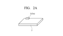
- FIG. 2A is a schematic view showing a configuration example of a print head which is mounted on the printer of the embodiment and performs printing on a print target.
- FIG. 2B is a schematic view showing a configuration example of a print head which is mounted on the printer of the embodiment and performs printing on a print target.
- FIG. 3A is a schematic diagram which shows the state which prints an image by moving the flight body by fixing the position of a print head. It is a figure which shows the operation state at the time of the image printing in the printer of embodiment, Comprising: FIG.
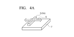
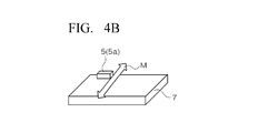
- 3B is a schematic diagram which shows the state which prints an image, when the position of a flying body is fixed and a printing head moves. It is a figure explaining the movement direction at the time of the printing head carried in the printer of an embodiment printing on printing object, and Drawing 4A is a mimetic diagram showing the composition of a printing head, and the variation of the movement direction. It is a figure explaining the movement direction at the time of the printing head carried in the printer of an embodiment printing on printing object, and Drawing 4B is a mimetic diagram showing the composition of a printing head, and the variation of the movement direction.
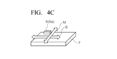
- Drawing 4C is a mimetic diagram showing the composition of a printing head, and the variation of the movement direction. It is a figure explaining the movement direction at the time of the printing head carried in the printer of an embodiment printing on printing object, and Drawing 4D is a mimetic diagram showing the composition of a printing head, and the variation of the movement direction. It is a figure explaining the movement direction at the time of the printing head carried in the printer of an embodiment printing on printing object, and Drawing 4E is a mimetic diagram showing the composition of a printing head, and the variation of the movement direction.
- FIG. 5A is a schematic diagram which shows the state holding distance by control of an aircraft. It is a figure which shows a means to hold
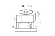
- FIG. 5B is a schematic diagram which shows the state holding the distance by the gap adjustment part provided in the flying body. .
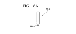
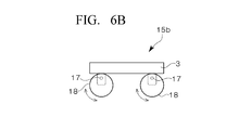
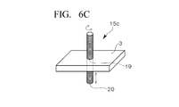
- FIG. 6A has shown the variation of the gap adjustment mechanism. It is a figure which shows more concretely the structure of the gap adjustment part in the printer of embodiment, Comprising: FIG. 6B has shown the variation of the gap adjustment mechanism. It is a figure which shows more concretely the structure of the gap adjustment part in the printer of embodiment, Comprising: FIG. 6C has shown the variation of the gap adjustment mechanism.
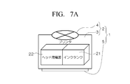
- FIG. 7A is a diagram showing the configuration of each part of a flying object having a print head, an ink supply source for supplying ink to the print head, and a head power source for driving the print head, wherein FIG.
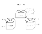
- FIG. 7B is a view showing the configuration of each part of a flying object having a print head, an ink supply source for supplying ink to the print head, and a head power source for driving the print head
- FIG. 7C is a diagram showing the configuration of each part of a flying object having a print head, an ink supply source for supplying ink to the print head, and a head power source for driving the print head
- FIG. 8A is a schematic view for explaining position control in a print target of the printer of the embodiment.
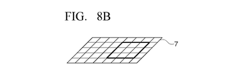
- FIG. 8B is a schematic view for explaining position control in the print target of the printer of the embodiment.
- FIG. 8C is a schematic view for explaining position control in the print target of the printer of the embodiment.
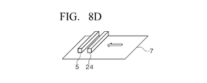
- FIG. 8D is a schematic view for explaining position control in the print target of the printer of the embodiment.
- It is a schematic diagram which shows the variation of the structure of the flight body in the printer of embodiment, and the moving mechanism of a printing head.
- FIG. 10A is a schematic view of a single printer, showing an embodiment of a printer that can be connected or disconnected. It is a figure which shows the printer of embodiment which can be connected or isolate
- FIG. 10B is a schematic diagram which shows the state which connected the two printers shown to FIG. 10A.
- FIG. 11A is a diagram showing a print path when forming an image on a print target by the printer of the embodiment which can be connected or separated, and FIG. 11A shows a predetermined image using a single print head of a single printer. It is a schematic diagram which shows the example which printed by the shortest printing path
- FIG. 11B is a diagram showing a print path when forming an image on a print target by the printer of the embodiment capable of being connected or separated, and FIG. 11B shows a predetermined image by two print heads of two connected printers. It is a schematic diagram which shows the example printed by the shortest printing path.
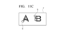
- FIG. 11C is a diagram showing a print path when forming an image on a print target with the printer of the embodiment capable of coupling or separation, and FIG.
- FIG. 11C uses two printers possessed by a single printer, each independently and simultaneously It is a schematic diagram which shows the example which printed the predetermined
- FIG. 11D is a view showing a print path when forming an image on a print target by the printer of the embodiment which can be connected or separated, and FIG. 11D shows predetermined images by three print heads of three connected printers.
- FIG. 11E is a diagram showing a print path when forming an image on a print target by the printer of the embodiment which can be connected or separated, and FIG. 11E uses two sets of connected three printers, and drives each independently at the same time It is a schematic diagram which shows the example which printed the predetermined
- a printer is an apparatus in which a print head is mounted on an unmanned flying object also called a drone.
- the flightable printer can fly by remote control or autonomously, and can print a desired image in a contactless manner on an approaching print target.
- Such a printer will be divided into items according to elements such as its configuration or control, and will be described with reference to FIGS. 1 to 11.
- the flightable printer 1 of the embodiment includes an unmanned air vehicle 2 also called a drone, and a print head 5 mounted on the air vehicle 2.
- the flying body 2 includes a main body 3 and a driving unit 4 mounted on the main body 3 to fly the main body 3.
- the drive part 4 is comprised with a single or several propeller and a motor etc. which drives this, it may be moving means other than a propeller etc., or a propulsion means.
- the print head 5 is attached to a predetermined position of the main body 3, which is the lower surface of the main body 3 in the example shown in FIG. 1.
- control unit 6 is housed in the main body unit 3.
- the control unit 6 controls not only the driving unit 4 and the print head 5 but also collectively controls other devices mounted on the main body unit 3.
- the control unit 6 controls the drive unit 4 and the like to fly the aircraft 2
- the flight may be a remote control flight or an autonomous flight.
- the flying object 2 receives the control signal under the control of the control unit 6, and based on the flight control information included in this
- the control signal is generated to control the drive unit 4 and the like to fly the flying object 2.
- the flying object 2 can approach the printing position and maintain a non-contact state suitable for printing by the print head 5.
- the control unit 6 can generate a print signal based on print control information included in the steering signal, thereby controlling the print head 5 and forming a designated image on a print target.
- a program necessary for autonomous flight necessary flight control information and printing control information are stored in the memory of the control unit 6 before flight.
- the flying object 2 After taking off from the departure point, the flying object 2 flies toward the print target and autonomously performs a series of operations for printing the designated image while approaching the print position and maintaining the non-contact state.
- the control of the printer 1 by the control unit 6 is not limited to that described in this section, and the control related to other functions of the printer 1 will be described as needed for each of the following sections.
- an ink tank as an ink supply source, and a battery for supplying power to a motor of a propeller and a pump of the ink tank are provided.
- print head 5 (Fig. 2) As shown in FIG. 2, there are a serial head 5 a and a line head 5 b as the print head 5 (also referred to as an inkjet head or an IJ head) mounted on the printer 1 of the embodiment.
- Each print head 5 is provided with an ink droplet generation mechanism that discharges ink in the form of droplets according to various principles.
- the ink droplet generation mechanism known thermal methods and piezo methods are known, but there is no particular limitation.
- the serial head 5a shown in FIG. 2A has a relatively small number of nozzles for ejecting ink as compared with the line head 5b described later.
- printing is performed while moving in one direction in the depth direction along the surface of the sheet corresponding to the print target 7 in FIG. 2A.
- the sheet corresponding to the print target 7 in the figure is moved in one direction in the horizontal direction by a predetermined pitch, and the serial head 5a is moved again in the other direction in the depth direction in the figure. Print. This scan is repeated to form an image on the entire surface of the printing paper.
- the printing by the serial head 5a includes the following method which does not involve the movement of the printing sheet. That is, printing is performed while moving in one direction in the depth direction in FIG. 2A, and when printing of one line is completed, the serial head 5a is moved by a predetermined pitch in one direction in the horizontal direction in the drawing. Printing is performed while moving in the other direction in the depth direction in the figure. Such scanning can be repeated to form an image on the entire surface of the printing paper.
- the line head 5b shown in FIG. 2B has a relatively large number of nozzles for ejecting ink as compared to the serial head 5a described above.
- the line head 5b is used in a normal inkjet printing apparatus, assuming that the depth direction of the sheet corresponding to the print target 7 in FIG. 2B is the width direction of the sheet, the length of the nozzle array of the line head 5b is the sheet The length exceeds the print area in the width direction.
- An image is formed on the entire surface of the printing paper by driving the line head 5b while moving the paper corresponding to the printing target 7 in the drawing in one direction in the horizontal direction in the drawing. Further, the printing by the line head 5b is performed by stopping the printing paper instead of moving the printing paper as well as moving the printing paper as described above, and making the line head 5b orthogonal to the longitudinal direction It is also conceivable to do while moving in the direction.
- FIG. 3 is a view showing the structure of the printer 1a according to the embodiment and the operation state at the time of image printing.
- the structure is different from that of the flying object 2 in the schematic structural view shown in FIG. That is, in the structural example of the flying object 2 a shown in FIG. 3, the annular frame 3 a is the main body 3.
- the annular frame 3a On the annular frame 3a, four arms 8 projecting outward in the radial direction are provided at equal intervals of 90 degrees with respect to the central angle of the annular frame 3a.
- a propeller 4a which is a drive unit 4 is provided at the tip of each arm 8, and the propeller 4a is driven by a motor or the like (not shown).
- the print head 5 is provided inside the annular frame 3a, but the mounting mechanism is different in FIGS. 3A and 3B.
- the print head 5 is attached to the inner center of the annular frame 3a by a fixed structure (not shown), and the print head 5 does not move relative to the annular frame 3a.
- the opening surface of the nozzle of the print head 5 protrudes slightly lower than the lower surface of the annular frame 3a, and is parallel to a plane including the annular frame 3a.
- the flying object 2 a is formed within the printing surface of the print target 7 while maintaining the distance between the flying object 2 a or the print head 5 and the print target 7 at a predetermined value.
- the control unit 6 drives the print head 5 while moving the flying object 2 a in a necessary direction to form an image on the print target 7.
- the aircraft 2 can be positioned in the same plane as required. You can take it.
- the print head 5 is fixed, but even if the print head 5 can move as shown in FIG. 3B described below, the flying object 2 can be moved without moving the print head 5. The same effect can be obtained by moving.
- the print head 5 is attached to the center of the inner side of the annular frame 3a by a moving mechanism (not shown), and the print head 5 is perpendicular to the arrow in the figure in the plane including the annular frame It can move arbitrarily about two directions shown by.
- the opening surface of the nozzle of the print head 5 protrudes slightly lower than the lower surface of the annular frame 3a, and is parallel to a plane including the annular frame 3a.
- the distance between the flying object 2a or the print head 5 and the print target 7 is maintained at a predetermined value, and the position of the flying object 2a in the horizontal plane is also fixed. Do. That is, hovering is performed in a state where the position of the flying object 2a is fixed with respect to the print target 7.
- the control unit 6 drives the print head 5 to form an image on the print target 7 while maintaining the flying body 2a in a predetermined position.
- the print head 5 By moving the print head 5 in at least two different directions, as shown by two bidirectional arrows orthogonal to each other in the plane of the annular frame 3a in FIG. 3B, at least within the movable range of the print head 5. An image can be formed.
- FIG. 3B while the flying object 2 is stopped at a predetermined position, the print head 5 is moved in two directions to perform image formation, but after image formation is performed at one location, the flying object 2 is located next to it. Can be moved and printed in the same manner to form a larger image continuous with the previous one.
- the flying object 2 is hovered so as to keep the distance of the flying object 2a to the printing object 7 at a predetermined value, but landing on the printing object 7 with landing legs for keeping the distance at a predetermined value It may be stationary and printing may be performed while moving the print head 5 there.
- the "distance" between the print head 5 and the print target 7 will be described later as a "gap", and the "landing leg" will be described later as a "gap adjustment unit".
- FIGS. 4A to 4F are schematic views showing the configuration of the print head 5 mounted on the printers 1 and 1a and variations in the movement direction thereof.
- the print target 7 is represented as a plate-like member, but this is a schematic expression, and the actual print target 7 is, for example, a part of the ground, a building, etc. It is printing paper etc.
- the print head 5 performs printing while holding a predetermined distance from the surface of the print target 7.
- the arrows in the figures indicate the moving direction of the print head 5.
- these two directions are referred to as the main scanning direction (see FIG. Although they are referred to as middle depth direction) and sub scanning direction (left and right direction in the drawing), there is no technically essential difference between the main and sub terms.
- the line head 5 b is used as the print head 5. If the nozzle array direction (longitudinal direction) of the line head 5b is the main scanning direction M, a desired image can be printed by moving the print head 5 in the sub scanning direction S orthogonal to this.
- the movement of the line head 5b in the sub scanning direction S may be performed by moving the line head 5b in the same direction with the flying objects 2 and 2a resting at a predetermined position, or the line head 5b is at rest It may be carried out by moving the flying bodies 2, 2a relatively in the same direction.
- the serial head 5 a is used as the print head 5.
- the serial head 5a is moved in the main scanning direction M.
- the movement of the serial head 5a in the sub scanning direction S with respect to the print target 7 may be performed by actually moving the serial head 5a in the sub scanning direction S while the flying objects 2 and 2a are at rest at predetermined positions.
- the serial head 5a may be moved by moving the flying objects 2 and 2a in the sub scanning direction S in a stationary state.
- the serial head 5 a is used as the print head 5.
- the serial head 5a is moved in the main scanning direction M and the sub scanning direction S.
- the flying object 2 stands still at a predetermined position, it is possible to print a desired image within the movable range of the serial head 5a.
- the flying object 2, 2a is moved to the adjacent area adjacent to the above range for printing, and a series of images beyond the range that can be covered by one printing are divided and printed in multiple times can do.
- the linear movement of each print head 5 in FIGS. 4A, 4B, and 4C described above can be performed using a known guide mechanism and a movement mechanism.
- the line head 5 b is used as the print head 5.
- One end of the line head 5 b is fixed to a rotation shaft 9 as a rotational movement mechanism attached to the main body 3 of the flying object 2.
- the line head 5b can be set to a position at a desired angle with respect to the rotational direction ⁇ by driving the rotational shaft 9.
- the serial head 5 a is used as the print head 5.
- the serial head 5 a is attached to a mechanism for rotation and linear movement attached to the main body 3 of the flying object 2.
- This mechanism is a linear motion mechanism that is rotatably attached to the main body 3 so as to adjust the angle (radian), and a linear motion mechanism that is attached to the rotational shaft 9 and can be optionally expanded and contracted in the radial direction R of the rotational shaft It has 10 and.
- the serial head 5 a is attached to the tip of the linear motion mechanism 10.
- the linear motion mechanism 10 can be set to a position of a desired angle with respect to the rotational direction ⁇ by driving the rotation shaft 9 and is at the tip of the linear motion mechanism 10 by expansion and contraction of the linear motion mechanism 10
- the serial head 5a can be set to a desired position in the radial direction R.
- the flying object 2, 2a is driven to move the flying object 2, 2a to the adjacent adjacent area for printing, and a series of images exceeding the coverage of one printing can be made multiple times. It can be divided and printed.
- FIGS. 4A to 4E described above it is assumed that the printing surface of the print target 7 is a flat surface, but FIG. 4F to be described next corresponds to the printing surface of the concave surface.
- the serial head 5 a is used as the print head 5.
- the serial head 5 a is attached to a solid angle moving mechanism having a function as a universal joint provided in the main body 3 of the flying object 2.
- This mechanism is rotatably mounted on the cylindrical base 11 attached to the main body 3 and an opening provided at the tip of the base 11 so that the solid angle (steradian) can be adjusted.
- a spherical joint portion 12 and a linear movement mechanism 13 attached to the circumferential surface of the spherical joint portion 12 and capable of reciprocating in any direction about the radial direction R of the joint portion 12 are provided.
- the serial head 5 a is attached to the tip of the linear motion mechanism 13.
- the joint portion 12 can be rotated within the adjustable solid angle range to set the linear movement mechanism 13 at a desired position with respect to the solid angle direction SR, and also the linear movement by expansion and contraction of the linear movement mechanism 13
- the serial head 5a at the tip of the mechanism 13 can be set to a desired position in the radial direction R.
- the following two structures can be considered as the configuration and movement direction of the print head 5 in the present embodiment.
- two flying bodies 2 and 2 are connected by a shaft, and a carriage on which the print head 5 is mounted is mounted in a state of being inserted through the shaft. This allows the carriage to translate along the shaft and pivot along the shaft.
- the print head 5 can be arbitrarily moved in two directions, the linear direction and the rotational direction.
- the print head 5 is mounted inside the annular first frame in a state where the print head 5 is inserted through the first shaft. Then, the first frame is mounted on the inside of the annular second frame which is larger than the first frame, with the first frame being supported by the second shaft oriented orthogonal to the first shaft.
- the print head 5 can rotate in two directions, that is, the rotation direction of the first shaft and the rotation direction of the second shaft.
- the printer 1 uses the print head 5 which is driven in a non-contact state with respect to the print target 7 and discharges ink droplets from the nozzles to form an image. For this reason, it is necessary to maintain the gap (referred to as a gap G) between the nozzle surface of the print head 5 and the print surface of the print target 7 as constant as possible.
- a gap G between the nozzle surface of the print head 5 and the print surface of the print target 7 as constant as possible.
- FIG. 5 is a view for explaining means for holding the gap G constant.
- FIG. 5A is a schematic view showing non-contact type gap adjustment in which the distance is maintained by control of the aircraft 2.
- the gap G is maintained at a necessary predetermined value by the control of the drive unit 4 and the like by the control unit 6, and the ink droplet ejected from the print head 5 is transferred to the print target 7 in an appropriate state. It is possible to form an image of The height control for maintaining the gap G at a required predetermined value will also be described in item 7 described later.
- FIG. 5B is a schematic view showing contact-type gap adjustment in which the gap G is held by the gap adjusting unit 15 provided in the aircraft 2.
- the gap adjusting unit 15 is a rod-like member set to the same length as the required gap G, and surrounds the print head 5 on the surface of the main body 3 of the flying object 2 on which the print head 5 is provided. At least three in parallel with each other (two appear in FIG. 5B). By bringing the gap adjustment unit 15 into contact with the print target 7, the gap G can be maintained at a required value.
- the printing accuracy of the print head 5 (IJ head) that performs drawing by discharging ink droplets is usually at the ⁇ m level.
- IJ head In order to achieve this level of printing accuracy in the printer 1 of the present embodiment, it is necessary to hold the gap G at a required value.
- the positioning accuracy by conventional drone flight control is usually at the cm level.
- the gap adjustment shown in FIG. 5B is performed in which the gap adjustment for holding the distance is performed by precise control of the flying object 2 or the gap G is maintained mechanically at a predetermined value. There is a need to do.
- FIG. 6 is a diagram of a variation more specifically showing the configuration of the gap adjusting unit.
- the gap adjusting unit 15a shown in FIG. 6A is a rod similar to the gap adjusting unit 15 shown in FIG. 5B, but a rotatable sphere 16 is attached to the tip thereof.
- the gap G is maintained constant. The print head 5 can be moved smoothly.
- FIG. 6B shows the gap adjusting unit 15 b attached to the surface of the flying object 2 in contact with the print target 7 of the main body 3.
- the gap adjusting unit 15b includes three or more cams 18 eccentrically mounted on the main body 3 via the shaft 17 (two cams 18 appear in FIG. 6B).
- the state of eccentricity of each cam 18 and the direction of rotation are the same, and the gap G can be set to a desired value by rotating the cam 18 by drive means (not shown).
- the cam 18 contacts the print target 7 at the periphery during printing, if the flying object 2 is moved parallel to the print target 7 in this state, the frictional force acting between the cam 18 and the print target 7 Is not large, and the printer 1 can be moved smoothly while maintaining the gap G constant.
- the gap adjusting unit 15 c illustrated in FIG. 6C is a gap adjusting mechanism provided so as to penetrate the main body 3 of the flying object 2 and to project the tip end toward the printing target 7.
- the gap adjusting units 15c are provided at three or more places surrounding the print head 5 (one gap adjusting unit 15c is shown in FIG. 6C).
- Each gap adjusting portion 15 c is provided on a wall of the main body portion 3, and thus includes a screw portion 19 and a screw shaft 20 that meshes with the female screw portion 19.
- a ball 16 may be provided at the tip of the screw shaft 20 in the same manner as the gap adjusting unit 15a of FIG. 6A.
- the gap G between the print head 5 and the printing surface When printing an image using the print head 5 (IJ head), it is better for the gap G between the print head 5 and the printing surface to be as small as possible. improves.
- the gap G may not be set small due to the roughness of the surface.
- the gap G can be set to an appropriate value depending on the state of the surface. If the state of the surface of the print target 7 can be predicted, an instruction may be given to the control unit 6 so that the gap adjustment units 15 b and 15 c can set necessary gaps G in advance. Alternatively, after the printer 1 actually approaches the vicinity of the print target 7, the surface of the print target 7 is observed by a camera or the like, and the gap adjustment units 15b and 15c set the necessary gap G according to the result. You may
- the printers 1 and 1a are devices for flying a flying object 2 or 2a carrying a print head 5 to approach a print target 7 and printing a desired image at a predetermined position of the print target 7. It is also assumed that the flying object 2, 2a is sent to approach the printing object 7 located at a high place or a distant place and the image is formed on a relatively large area of the printing object 7. For that purpose, it is preferable that an ink supply source for supplying ink to the print head 5 and a head power supply for driving the print head 5 have a corresponding capacity.
- FIG. 7A is a schematic view showing an integrated structure in which an ink tank 21 as an ink supply source and a head power source 22 for driving the print head 5 are housed in the main body 3 of the printer 1.
- the configuration is simpler and the manufacturing cost is lower than that of the independent type (FIG. 7B) or the separate connection type (FIG. 7C) described later.
- they are large and heavy as a whole. For this reason, it becomes more difficult to keep the gap G constant by flight control and to print an image by moving the printer itself as described with reference to FIG. 3A. Therefore, as the gap adjustment method described with reference to FIG. 5, the contact type (FIG. 5B) is preferable to the noncontact type (FIG. 5A), and the choice of the gap adjustment method is narrowed.
- the print head 5 can be used for a long time Since a large amount of stored ink can be supplied to the print head 5 over a wide range of images can be printed on the print target 7.
- FIG. 7B the ink tank 21 and the head power supply 22 for driving the print head 5 are separated from the printer 1 and provided with the flight driving unit 4 so that they can fly independently.
- the ink tank 21 and the print head 5 of the flying object 2 are connected in advance by a tube or the like, or the ink tank 21 or the print head 7 is approached.
- a tube or the like is extended from the side of the flying object 2 and connected to the other side, and the ink is supplied from the ink tank 21 to the print head 5.
- the head power supply 22 supplies power to the print head 5 in a wired or wireless manner. Therefore, the ink tank 21 and the head power supply 22 independent of the printer 1 may be hovering in the vicinity of the printer 1. That is, the ink tank 21 and the head power supply 22 do not have to perform position control with high accuracy like the printer 1 which performs printing by the print head 5.
- the ink tank 21 and the head power supply 22 land near the flying object 2. It may be In that case, the ink tank 21 and the head power supply 22 are stopped, and there is no need for position control.
- the printer 1 can be configured to be smaller and lighter than the case where the ink tank 21 and the head power supply 22 are built in, high-precision position control of the flying body 2 for image formation is It can be done more easily than when it is heavy and large.
- FIG. 7C the ink tank 21 and the head power supply 22 are separated from the printer 1 and provided with a drive unit 4 for flight independently to enable flight independently. It is a schematic diagram of the structure which enabled it to connect or isolate
- the printer 1, the ink tank 21, and the head power supply 22 can be arbitrarily connected to each other and separated as needed. Therefore, the number, type, and combination of the printers 1 can be arbitrarily determined in accordance with the design, size, etc. of the image to be printed. For example, the necessary number of printers 1 can be combined in a line to form a line head configuration, and the area that can be printed in one operation can be increased. Further, it is possible to arbitrarily combine a plurality of printers 1 mounted with print heads 5 having different colors of ink to be ejected, so that multi-color printing can be performed by one operation.
- the used ink tank 21 and the head power source 22 are separated from the printer 1 and returned to the departure point. .
- the printer 1 is kept in the vicinity of the print target 7.
- a full ink tank 21 and a charged head power supply 22 are newly dispatched from the departure point to the vicinity of the print target 7 and connected to the printer 1 kept in the vicinity of the print target 7. You can now continue printing.
- the ink tank 21 is provided with a pump for delivering the ink.
- a head power source 22 may be used to drive the pump, or a power source dedicated to the pump may be provided in the ink tank 21.
- the printer 1 takes off from the departure point and flies to the destination, confirms the print target 7 and approaches the necessary distance, and holds the gap G between the print target 7 and the print head.
- the image 5 is printed to print the designated image by driving 5.
- flight control to the destination and flight control for approaching the print target 7 in the upper sky of the destination are performed as described below.
- Flight Control to the Destination Position control when moving from the departure position to the print target 7 includes control of the altitude position and the plane position, and can be performed by control using GPS.
- the printer 1 that has reached the sky above the destination which is the print target 7 captures an image of the ground surface with the camera 23, and acquires image data of a predetermined area.
- the printer 1 stores in advance the data on the characteristic pattern on the ground surface to be printed in the control unit 6.
- the control unit 6 of the printer 1 recognizes the image data acquired for the range shown in FIG. 8A through a coordinate system constituted by a grid in which one or a plurality of pixels are in a unit. Then, the image data is compared with the pattern given in advance, and it is searched whether the pattern is present in the image data.
- a pattern matching the pattern is recognized in the image data
- a plurality of grids surrounding the grid in which the pattern is recognized is specified in the coordinate system of the image data. In FIG. 8B, nine grids surrounded by thick lines are identified (this is referred to as a specific grid group).
- the printer 1 increases the magnification of the camera 23 or lowers the flying object 2 to expand the range of the image captured by the camera 23 from the state of FIG. 8B to the state of FIG. Let's narrow down the position of.
- each grid of the specific grid group is given a number from 1 to 9, and the grid in which the pattern is recognized is indicated by the number 5.
- the printer 1 is lowered to the position of the specific grid group shown in FIG. 8C and, as shown in FIG. 8D, along the direction of the arrow from one edge of the specific grid group to the other edge,
- the ground surface of the print target 7 is scanned by a CIS 24 (Contact Image Sensor, contact image sensor) as a mounted image acquisition device.
- CIS 24 Contact Image Sensor, contact image sensor
- the print head 5 is driven to print the designated image at the position of the pattern (No. 5 grid).
- the image acquisition device is not limited to the CIS, and may be a CCD, a CMOS, etc., and the type need not be limited technically.
- another camera may be mounted in addition to the camera 23 so that the altitude can be measured as a dual camera.
- the altitude may be measured by laser measurement or ultrasonic measurement.
- the image acquired by the camera 23 is recognized through a coordinate system having pixels as a structural unit, and the same pattern as the pattern is searched for. An existing grid was extracted from the image.
- the specification of the position of the pattern may be performed by another method other than the coordinateization.
- the camera 23 of the printer 1 floating in the air acquires the entire image obtained by photographing a relatively wide area of the ground surface, and approaches and descends the relatively narrow portion in which the pattern is detected.
- By acquiring a partial image obtained by photographing a part and collating the patterns of the whole image and the partial image it is possible to acquire position information of a printing position indicating which position in the whole image the pattern is at.
- Flight control to approach the target point of printing target 7 (2) Separately from the printer 1, a flying object provided with a camera is prepared. By shooting the printer 1 with this shooting flight object, flight control can be performed to make the printer 1 approach the target point of the print target 7. That is, if the printer 1 in the lower part is photographed with the photographing flying object disposed above, an image is obtained in which the printer 1 appears to be superimposed on the image of the ground surface to be printed 7.
- the position control information may be sent from the flying object 2 for imaging to the printer 1 so as to go to the target point.
- image data captured by a shooting flying object may be sent to the printer 1, and the control unit 6 of the printer 1 may generate position control information by itself and head toward a target point.
- the print target image captured by the camera is compared with the stored print target pattern to specify the print position, and the print position is specified. Since the image sensor is moved to form an image when the pattern is actually detected by the image sensor, the image is printed with an accurate positional accuracy even at a target position set as a print target located away from the starting point. Can.
- FIG. 1 is schematically shown as a structure in which a single propeller is provided on the upper surface of a rectangular box.
- FIG. 3 shows a more specific structure in which four propellers are provided on the annular frame 3a. Even with such a structure, as described above, printing can be performed not only on the ground surface but also on the lower surface, the side surface, and the concave surface of the structure by appropriately controlling the attitude of the machine. .
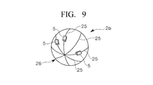
- FIG. 9 shows a flying object 2b for performing printing without difficulty on the lower surface, the side surface, the concave surface, etc. of the structure.
- the flying object 2 b includes a spherical main body 26 in which a plurality of annular frames 25 are combined.
- a propeller (not shown) inside the main body 26 and it can fly.
- a control unit inside the main body 26 and it can fly.
- a control unit inside the main body 26 and it can fly.
- a control unit, a tank, a power supply, a camera and the like are provided.
- the print head 5 is movably provided at least in a portion other than the frame 25 and the connection portion of the frame 25.
- the nozzle surface of the print head 5 is configured to be capable of holding the gap G even when the flying object 2 contacts the print target 7.
- Each print head 5 can be moved to any position along the frame 25 within an angle range of about 180 degrees, and the flying object 2b can be arbitrarily rotated to control its attitude, so that
- a desired image can be printed without difficulty on the inside of the cylinder or on the inner surface (lower surface) of the dome ceiling.
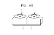
- the printer 1 shown in FIG. 10A has substantially the same configuration as the printer 1 shown in FIG. 1, but as shown in FIG. 10B, two units can be connected side by side along the longitudinal direction of the print head 5. Although not shown, three or more units can be similarly connected.
- the plurality of connected printers 1 can fly like a single printer 1 under the control of the control unit 6. When connected, the print heads 5 of the plurality of printers 1 are integrated as a printing unit. That is, a plurality of print heads 5 can be connected to form a print head longer than that of a single printer 1.
- the state of the nozzle arrangement is the same as the other parts, and the arrangement pattern of the nozzles or the nozzle pitch is constant as a whole.
- the print head 5 of each printer 1 may be the serial head 5a or the line head 5b.
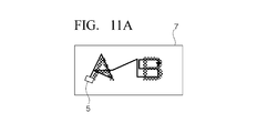
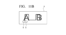
- FIG. 11 is a diagram showing a print path when forming an image on the print target 7 by the printer 1 of the embodiment which can be connected or separated.
- the image to be printed on the print target 7 is indicated by the characters "A" and "B", and the locus along which the print head 5 moves, that is, the print path is indicated by a solid arrow.
- the printer 1 moves in the shortest movement path while maintaining the gap G with the print target 7 alone or in a state of connecting a plurality of printers. While printing, the print head 5 can be driven to print an image. Alternatively, the printer 1 is stopped alone or in a state in which a plurality of units are connected while keeping the gap G above the print target 7, and the print head 5 is moved in the shortest movement path to print an image. can do. Whether the printer 1 itself moves, or the printer 1 stops and the print head 5 moves, or which one to select depends on the relative comparison between the size of the image to be printed and the range that can be printed by the printer 1 You can decide.
- FIG. 11A shows an example in which the characters “A” and “B” are printed in the shortest printing path with a single print head 5 of the single printer 1 shown in FIG. 10A.
- FIG. 11B uses the printer 1 of FIG. 10B in which two printers 1 of FIG. 10A are connected, and the letters “A” and “B” are printed in the shortest print path by two print heads 5 integrated An example is shown.
- FIG. 11C uses the single printer 1 shown in FIG. 10A in two machines, and simultaneously drives the respective print heads 5 independently to print the characters “A” and “B” simultaneously in the shortest printing path. An example is shown.
- FIG. 11D uses the printer 1 in which three single printers 1 shown in FIG. 10A are connected, and the letters “A” and “B” are printed in the shortest printing path with three print heads 5 integrated An example is shown.
- FIG. 11E uses two sets of three connected printers 1 and simultaneously drives the three integrated print heads 5 of each set independently at the same time to minimize the letters “A” and “B” respectively.
- An example in which printing is performed simultaneously in the print path is shown.
- the printing time can be shortened as much as possible by moving the flying object 2 or the print head 5 in the shortest route as described above according to the size, arrangement, etc. of the image to be printed. it can. Also, the printing time can be shortened as much as possible by appropriately setting the number of connected printers 1 in accordance with the print content.
- the print head discharges ink droplets to print an image on the surface to be printed
- the liquid discharged from the print head is not limited to ink.
- silver paste can be discharged to print a circuit pattern.
- it can be used like a 3D printer which forms a three-dimensional structure by discharging and stacking resin.
- an adhesive can be discharged.
- the edible paste can be discharged onto the surface of the food to perform the necessary printing.
- the repair material can be discharged to repair cracks in the structure.
- a windproof wall may be provided on the printing target side of the main body of the printer 1, 1a.
- the size of the wall preferably surrounds the periphery of the print head 5 and generally closes the gap G, but does not contact the print target.
- the printer of the first aspect by flying the flying object from the departure point to the vicinity of the print target and driving the print head with respect to the print target in a non-contact state, the desired image is printed on the print target. It can be printed.
- the flying body has a main body portion, and a drive portion mounted on the main body portion to fly the main body portion.
- the print head is attached to a predetermined position of the main body,
- the apparatus further includes a control unit that drives the print head while moving the flying object while maintaining the distance between the flying object and the printing target at a predetermined value.
- the printing object while the distance between the flying object and the printing object is maintained at a predetermined value, the printing object is driven by moving the flying object within the printing surface of the printing object to drive the print head.
- the desired image can be printed.
- the printer according to the third aspect is the printer according to the first aspect,
- the flying body has a main body portion, and a drive portion mounted on the main body portion to fly the main body portion.
- the print head is mounted so as to be arbitrarily movable in at least two different directions with respect to the main body;
- the control apparatus may further include a control unit that moves and drives the print head while fixing the position of the flying object with respect to the print target.
- the desired image is printed on the print target by driving while moving the print head within the print surface of the print target while fixing the position of the flying object with respect to the print target Can.
- the printer of the fourth aspect is the printer according to the second or third aspect,
- the control unit is characterized in that the control unit controls the drive unit to hold the distance between the flying object and the printing target at a predetermined value when printing an image.
- the printer of the fourth aspect when printing an image on a print target, the distance between the print head and the print target can be maintained at a predetermined value by controlling the drive unit of the flying object. For this reason, a desired image can be printed with good image quality regardless of the state of the surface to be printed.
- the printer of the fifth aspect is the printer of the second or third aspect, wherein
- the printing apparatus is characterized in that it has a gap adjusting unit attached to the main body and held in contact with the print target when printing an image to hold the distance between the print head and the print target at a predetermined value.
- the gap adjustment unit attached to the main body of the flying object abuts on the print target, so the distance between the print head and the print target is specified. Can be held at the value of For this reason, a desired image can be printed with good image quality regardless of the state of the surface to be printed.
- the printer of the sixth aspect is the printer according to any one of the first to fifth aspects, wherein It is characterized by having an ink supply source for supplying ink to the print head, and a head power supply for driving the print head.
- the ink supply source for supplying ink to the print head and the head power supply for driving the print head are provided, a large amount of ink can be supplied to the print head.
- the print head can be driven for a long time, a large-area image can be printed on the print target.
- a printer according to a seventh aspect is the printer according to the sixth aspect, It is characterized in that the ink supply source can fly independently by a drive for flight, and the head power supply can fly independently by a drive for flight.
- the ink supply source and the head power supply are independent of the flying object on which the print head is mounted, but the ink can be supplied to the print head by a tube or the like, and the power supply is wired Or, it can be supplied to the print head wirelessly.
- the ink supply source and the head power supply independent of the flying object may be hovering in the vicinity of the flying object. That is, the ink supply source and the head power source do not have to perform position control with high accuracy as in the case of a flying object printing with the print head.
- the flying object mounted with the print head can be configured to be smaller and lighter than the case where the ink supply source and the head power supply are incorporated. For this reason, highly accurate position control of the flying body for image formation can be performed more easily than when the body is heavy and large.
- the printer according to the eighth aspect is the printer according to the seventh aspect, It is characterized in that the ink supply source and the head power source can be respectively connected to or separated from the flying object.
- the flying object equipped with the print head, the ink supply source, and the power supply for the head can be arbitrarily connected and separated from each other, the design of the image to be printed Depending on the size and the like, the number and combination of the flying bodies equipped with the print head can be arbitrarily determined. For example, the required number of flying objects can be combined in a line to increase the area that can be printed in one operation as a line head configuration. In addition, it is possible to arbitrarily combine a plurality of flying bodies mounted with print heads having different colors of ink to be ejected, so that multi-color printing can be performed in one operation.
- the used ink supply source and the head power supply are separated from the flying object and returned to the departure point.
- the flying object is kept near the print target.
- a full ink supply source and a fully charged head power supply are newly dispatched from the departure point to the vicinity of the print target, and connected to the flying object kept in the vicinity of the print target. You can now continue printing. In order to avoid interruptions in printing, wait until the ink supply for the ink supply and the power for the head power supply are exhausted, and wait for the ink supply for the full tank and the power supply for the fully charged head to be close to the print target. You may leave it.
- a printer according to a ninth aspect is the printer according to any one of the first to eighth aspects, wherein The control unit controls at least one of the flying object and the print head so as to print an image to be printed in a shortest moving path.
- the printing time can be shortened as much as possible by moving the flying object or the print head in the shortest route according to the image to be printed. Also, the printing time can be shortened as much as possible by appropriately setting the number of connected printers according to the image to be printed.
- the printer according to the tenth aspect is the printer according to any one of the first to ninth aspects, wherein A camera for acquiring an image to be printed, An image sensor that detects the pattern of the print target; And have The control unit stores in advance a pattern of a print target to be a target, collates the pattern with an image of the print target acquired by the camera to specify a print position, and moves the flying object to the print position And controlling the flying object and the print head to scan an object to be printed by the image sensor and print an image at a position where the pattern is detected.
- the print position is determined by comparing the image of the print target photographed with the camera with the pattern of the print target stored, move to the print position, and form an image when the pattern is actually detected by the image sensor Because of this, it is possible to print an image with an accurate position accuracy with respect to the target position set for the print target at a position distant from the starting point.
Landscapes
- Engineering & Computer Science (AREA)
- Aviation & Aerospace Engineering (AREA)
- Mechanical Engineering (AREA)
- Remote Sensing (AREA)
- Ink Jet (AREA)
- Printers Characterized By Their Purpose (AREA)
- Common Mechanisms (AREA)
- Record Information Processing For Printing (AREA)
Abstract
【課題】飛行体に印刷装置を搭載した飛行可能なプリンタで印刷対象面に非接触で所望の画像を印刷すること。 【解決手段】プリンタ1は、本体部3と制御部6と駆動部4を有する飛行体2と、飛行体に搭載され、飛行体が接近した印刷対象に非接触で所望の画像を印刷する印刷ヘッド5を備えている。飛行体の本体部に取り付けたギャップ調整部15を印刷対象7に当接させるか、駆動部の精密な制御によってギャップGを所定の値に保持しつつ印刷ヘッドを駆動する。印刷対象の表面の状態に係わらず、所望の画像を良好な画質で印刷することができる。
Description
本発明は、ドローンと呼ばれる無人の飛行体に印刷ヘッドを搭載してなるプリンタに係り、特に、飛行して印刷対象に接近し、印刷対象に対して非接触の状態で所望の画像を形成することができるプリンタに関するものである。
下記特許文献1にはマルチコプターの発明が開示されている。このマルチコプター3は、複数のローター11を備えた自己昇降する構造体1に、真空吸着ユニット2と、清掃装置4を備えたものである。このマルチコプターは、独力で自動的に飛行して対象位置の表面まで到達し、独力で表面上を移動し、また表面から離れることができる飛行性能を備えている。そして、この発明によれば、清掃装置4に代えて印刷装置4を装備することもできるものとされている。
上記特許文献1の記載によれば、このマルチコプターの印刷装置4はローラ状の構造であり、対象に接触して塗料を塗布する塗布ローラと考えられる。従って、このマルチコプターは、移動先の壁面等に吸着装置で吸いついて印刷装置の塗布ローラを壁面に接触させ、その状態でローターを駆動して壁面に沿って移動しながら塗布ローラで当該壁面に印刷を行うものと考えられる。
上記特許文献1に開示された発明によれば、印刷対象面に接触して印刷を行うため、印刷対象面の状況によっては印刷が不可能又は困難な場合が考えられる。特に、飛行体に塗布ローラを搭載した印刷装置であるから、遠隔地や、通常は接近が困難な場所まで飛行して印刷作業を行う場合が多いと想定されるが、遠隔または接近困難な現場に到達した後に、印刷対象面が接触印刷に適さない状態であると判明したとしても、適切な対応をとることができない場合が考えられる。また、塗布ローラを印刷対象面に接触させて転動させながら塗料を塗る方法では、予定した大まかな形状に塗料を塗る作業は実行できても、一般的に所望のパターンで画像を印刷することは困難であった。
本発明は、このような従来の技術及びその課題に鑑みてなされたものであり、飛行体に印刷装置を搭載した飛行可能なプリンタであって、飛行して到達した印刷対象面に非接触で所望の画像を印刷できるプリンタを提供することを目的としている。
請求項1に記載されたプリンタは、
飛行体と、
前記飛行体に搭載され、前記飛行体が接近した印刷対象に非接触で所望の画像を印刷する印刷ヘッドと、
を有している。
飛行体と、
前記飛行体に搭載され、前記飛行体が接近した印刷対象に非接触で所望の画像を印刷する印刷ヘッドと、
を有している。
請求項1に記載されたプリンタによれば、飛行体を出発地点から印刷対象の近傍まで飛行させ、印刷対象に対して印刷ヘッドを非接触の状態としながら駆動することにより、印刷対象に所望の画像を印刷することができる。
本発明の実施形態に係るプリンタは、ドローンとも呼ばれる無人の飛行体に印刷ヘッドを搭載した装置である。この飛行可能なプリンタは、遠隔操縦により又は自律的に飛行し、接近した印刷対象に対して非接触で所望の画像を印刷することができる。このようなプリンタについて、その構成又は制御等の要素ごとに項分けし、図1~図11を参照して説明する。
1.飛行体の基本構成について(図1)
図1に示すように、実施形態の飛行可能なプリンタ1は、ドローンとも呼ばれる無人の飛行体2と、この飛行体2に搭載された印刷ヘッド5とを備えている。飛行体2は、本体部3と、本体部3に搭載されて本体部3を飛行させる駆動部4を備えている。駆動部4は、単数又は複数のプロペラと、これを駆動するモータ等で構成されるが、プロペラ等以外の移動手段又は推進手段であってもよい。印刷ヘッド5は、本体部3の所定位置、図1に示す例では本体部3の下面に取り付けられている。
図1に示すように、実施形態の飛行可能なプリンタ1は、ドローンとも呼ばれる無人の飛行体2と、この飛行体2に搭載された印刷ヘッド5とを備えている。飛行体2は、本体部3と、本体部3に搭載されて本体部3を飛行させる駆動部4を備えている。駆動部4は、単数又は複数のプロペラと、これを駆動するモータ等で構成されるが、プロペラ等以外の移動手段又は推進手段であってもよい。印刷ヘッド5は、本体部3の所定位置、図1に示す例では本体部3の下面に取り付けられている。
なお、プロペラを駆動部4とする飛行体2の場合であっても、必ずしもプロペラを上にした状態でしか飛行できないわけではない。例えば、プロペラを横にして本体部3が横倒しになった状態で飛行しつつ、垂直な壁に印刷ヘッド5で印刷することも可能である。また、プロペラを下に向け、本体部3が逆さまになった状態で飛行しつつ、天井に印刷ヘッド5で印刷することも可能である。プロペラ以外の他の駆動部4を有する飛行体2でも同様である。
図1に示すように、本体部3内には、制御部6が収納されている。制御部6は、駆動部4と印刷ヘッド5を制御する他、本体部3に搭載されたその他の機器も統括して制御する。制御部6が駆動部4等を制御して飛行体2を飛行させる場合、その飛行は、遠隔操縦による飛行であってもよいし、自律的な飛行であってもよい。
すなわち、遠隔操縦の場合には、操縦者が操縦装置から操縦信号を送信すると、飛行体2では制御部6の制御のもと、操縦信号を受信し、これに含まれる飛行制御情報に基づいた制御信号を生成して駆動部4等を制御し、飛行体2を飛行させる。飛行体2は、印刷位置に接近し、印刷ヘッド5による印刷に適した非接触の状態を維持することができる。なお、制御部6は、操縦信号に含まれる印刷制御情報に基づいて印刷信号を生成し、これによって印刷ヘッド5を制御し、指定された画像を印刷対象に形成することができる。
また、自律的な飛行の場合には、自律飛行に必要なプログラムと、必要な飛行制御情報及び印刷制御情報を飛行前に制御部6のメモリに記憶させておく。飛行体2は出発地点から離陸した後、印刷対象に向けて飛行し、印刷位置に接近して非接触の状態を維持しながら、指定された画像を印刷する一連の作業を自律的に行う。
なお、制御部6によるプリンタ1の制御は本項で説明したものだけではなく、本プリンタ1の他の機能に係わる制御については、以下の各項ごとに必要に応じて説明する。
なお、制御部6によるプリンタ1の制御は本項で説明したものだけではなく、本プリンタ1の他の機能に係わる制御については、以下の各項ごとに必要に応じて説明する。
図1には示していないが、本体部3内には、インク供給源であるインクタンクと、プロペラのモータとインクタンクのポンプに電源を供給するバッテリーとが設けられている。
2.印刷ヘッド5について(図2)
図2に示すように、実施形態のプリンタ1に搭載する印刷ヘッド5(インクジェットヘッド、IJヘッドとも称する。)としては、シリアルヘッド5aとラインヘッド5bがある。いずれの印刷ヘッド5も、各種原理によりインクを液滴状にして吐出するインク滴生成機構を備えている。インク滴生成機構としては、公知のサーマル方式やピエゾ方式が知られているが、特に限定するものではない。
図2に示すように、実施形態のプリンタ1に搭載する印刷ヘッド5(インクジェットヘッド、IJヘッドとも称する。)としては、シリアルヘッド5aとラインヘッド5bがある。いずれの印刷ヘッド5も、各種原理によりインクを液滴状にして吐出するインク滴生成機構を備えている。インク滴生成機構としては、公知のサーマル方式やピエゾ方式が知られているが、特に限定するものではない。
図2(a)に示すシリアルヘッド5aは、インクを吐出するノズルの数が後述するラインヘッド5bに比べて相対的に少ない。シリアルヘッド5aを、通常のインクジェット印刷装置で使用する場合には、図2Aの印刷対象7に相当する用紙の表面沿いに奥行き方向の一方向に移動しながら印字を行う。一行の印字が完了すると、図中の印刷対象7に相当する用紙を図中左右方向の一方向に所定ピッチだけ移動させ、再度、シリアルヘッド5aを同図において奥行き方向の他方向に移動しながら印字を行う。この走査を繰り返して印刷用紙の全面に画像を形成する。また、シリアルヘッド5aによる印字は、上述のように印刷用紙の移動を伴う方法の他、印刷用紙の移動を伴わない次のような方法もある。すなわち、図2Aにおいて奥行き方向の一方向に移動しながら印字を行い、一行の印字が完了すると、図中左右方向の一方向に所定ピッチだけシリアルヘッド5aを移動させ、再度、シリアルヘッド5aを同図において奥行き方向の他方向に移動しながら印字を行う。このような走査を繰り返して印刷用紙の全面に画像を形成することもできる。
図2Bに示すラインヘッド5bは、インクを吐出するノズルの数が前述したシリアルヘッド5aに比べて相対的に多い。ラインヘッド5bを、通常のインクジェット印刷装置において使用する場合には、図2Bの印刷対象7に相当する用紙の奥行き方向を用紙の幅方向とすると、ラインヘッド5bのノズル列の長さは、用紙の幅方向の印字領域を越える長さとなっている。図中の印刷対象7に相当する用紙を図中左右方向の一方向に移動しながら、ラインヘッド5bを駆動することにより、印刷用紙の全面に画像を形成する。また、ラインヘッド5bによる印字は、上述のように印刷用紙の移動を伴う方法の他、印刷用紙を移動させる代わりに、印刷用紙を停止させておき、ラインヘッド5bを、その長手方向と直交する方向に移動しながら行うことも考えられる。
3.印刷時の飛行体2又は印刷ヘッド5の移動方向について(図3)
印刷時の飛行体2又は印刷ヘッド5の移動方向について説明する。
シリアルヘッド5a又はラインヘッド5bによって通常のインクジェット印刷装置で用紙に画像を印刷する場合には、上述したように印刷ヘッド5自体の移動のみでも行えるが、印刷ヘッド5と用紙の両方を移動させることでも可能であった。これに対し、本実施形態では、印刷ヘッド5は飛行体2によって移動可能であるが、印刷対象7は、印刷用紙だけでなく、地面や通常は移動できない建造物その他の重量物等の外面等も含む。そして、これらの印刷対象7に画像を形成する場合には、飛行体2を移動させるとともに印刷ヘッド5も移動させて印刷する場合と、飛行体2は位置を固定して印刷ヘッド5自体の移動のみで印刷を行う場合とが考えられる。
印刷時の飛行体2又は印刷ヘッド5の移動方向について説明する。
シリアルヘッド5a又はラインヘッド5bによって通常のインクジェット印刷装置で用紙に画像を印刷する場合には、上述したように印刷ヘッド5自体の移動のみでも行えるが、印刷ヘッド5と用紙の両方を移動させることでも可能であった。これに対し、本実施形態では、印刷ヘッド5は飛行体2によって移動可能であるが、印刷対象7は、印刷用紙だけでなく、地面や通常は移動できない建造物その他の重量物等の外面等も含む。そして、これらの印刷対象7に画像を形成する場合には、飛行体2を移動させるとともに印刷ヘッド5も移動させて印刷する場合と、飛行体2は位置を固定して印刷ヘッド5自体の移動のみで印刷を行う場合とが考えられる。
図3は、実施形態のプリンタ1aの構造と、画像印刷時の作動状態を示す図である。
図3A、図3Bのいずれの図においても、図1に示した模式構造図の飛行体2とは構造が異なっている。すなわち、図3に示した飛行体2aの構造例では、環状フレーム3aを本体部3としている。この環状フレーム3aには、半径方向に沿って外方向に突出した4本のアーム8が、環状フレーム3aの中心角度に関して90度の等間隔で設けられている。各アーム8の先端には、駆動部4であるプロペラ4aが設けられており、プロペラ4aは図示しないモータ等で駆動される。環状フレーム3aの内側には、印刷ヘッド5が設けられているが、その搭載の機構が図3Aと図3Bで異なっている。
図3A、図3Bのいずれの図においても、図1に示した模式構造図の飛行体2とは構造が異なっている。すなわち、図3に示した飛行体2aの構造例では、環状フレーム3aを本体部3としている。この環状フレーム3aには、半径方向に沿って外方向に突出した4本のアーム8が、環状フレーム3aの中心角度に関して90度の等間隔で設けられている。各アーム8の先端には、駆動部4であるプロペラ4aが設けられており、プロペラ4aは図示しないモータ等で駆動される。環状フレーム3aの内側には、印刷ヘッド5が設けられているが、その搭載の機構が図3Aと図3Bで異なっている。
図3Aに示す例では、環状フレーム3aの内側の中心に、印刷ヘッド5が図示しない固定構造で取り付けられており、印刷ヘッド5は環状フレーム3aに対して移動しない。印刷ヘッド5のノズルの開口面は、環状フレーム3aの下面よりもやや下方に突出しており、環状フレーム3aを含む平面と平行になっている。
このプリンタ1aで印刷対象7に画像を形成するには、飛行体2a又は印刷ヘッド5と、印刷対象7との距離を所定の値に保持しつつ、印刷対象7の印刷面内において飛行体2aを移動させながら印刷ヘッド5を駆動することにより、印刷対象7に所望の画像を印刷する。すなわち、印刷時には、制御部6が飛行体2aを必要な方向に移動させながら印刷ヘッド5を駆動して印刷対象7に画像を形成する。図3A中に直交する2本の双方向の矢印で示すように、環状フレーム3aの平面内で少なくとも異なる2方向に飛行体2を移動させることにより、飛行体2は同平面内において必要な位置取りをすることができる。図3Aでは、印刷ヘッド5が固定であるものとしたが、印刷ヘッド5が次に説明する図3Bのように移動できる場合であっても、印刷ヘッド5を移動させずに、飛行体2を移動させることで同様の効果を得ることができる。
図3Bに示す例では、環状フレーム3aの内側の中心に、印刷ヘッド5が図示しない移動機構で取り付けられており、印刷ヘッド5は、環状フレーム3aを含む平面内において、図中の直交する矢印で示す2方向について任意に移動することができる。印刷ヘッド5のノズルの開口面は、環状フレーム3aの下面よりもやや下方に突出しており、環状フレーム3aを含む平面と平行になっている。
このプリンタ1aで印刷対象7に画像を形成するには、飛行体2a又は印刷ヘッド5と、印刷対象7との距離を所定の値に保持しつつ、飛行体2aの水平面内での位置も固定する。すなわち、印刷対象7に対して飛行体2aの位置を固定した状態でホバリングする。この状態で印刷ヘッド5を駆動することにより、印刷対象7に所望の画像を印刷する。すなわち、印刷時には、制御部6が、飛行体2aを所定の位置に浮かせた状態を維持しながら印刷ヘッド5を駆動し、印刷対象7に画像を形成する。図3B中に環状フレーム3aの平面内で直交する2本の双方向の矢印で示すように、少なくとも異なる2方向に印刷ヘッド5を移動させることにより、少なくとも印刷ヘッド5の移動可能な範囲内において画像を形成することができる。図3Bでは、飛行体2を所定位置に停止させた状態で印刷ヘッド5を2方向に移動させて画像形成を行ったが、一カ所で画像形成を行った後、隣の位置に飛行体2を移動させて同様に印刷を行えば、前の画像と連続したより大きな画像を形成することもできる。
なお、印刷対象7に対する飛行体2aの距離を所定の値に保つように飛行体2をホバリングさせるものとしたが、前記距離を所定の値に保つ着陸脚で印刷対象7の上に着陸して静止し、そこで印刷ヘッド5を移動しながら印刷を行ってもよい。なお、印刷ヘッド5と印刷対象7の前記「距離」については、後に「ギャップ」として説明し、また前記「着陸脚」については、後に「ギャップ調整部」として説明する。
4.印刷ヘッド5が印刷対象7に印刷を行う際の移動方向について(図4)
図4A~図4Fは、プリンタ1,1aに搭載された印刷ヘッド5の構成と、その移動方向のバリエーションを示す模式図である。なお、各分図中、印刷対象7は板状の部材のように表しているが、これは模式的な表現であって、実際の印刷対象7は、例えば地面、建造物等の一部や印刷用紙等である。前述した通り、印刷ヘッド5は、印刷対象7の表面から所定の距離を保持した状態で印刷を行う。また、各図中の矢印は印刷ヘッド5の移動方向を示しており、平面内で直交する2方向の場合、印刷用紙に印刷する場合の例に倣って、この2方向を主走査方向(図中奥行き方向)及び副走査方向(図中左右方向)と称しているが、主・副の用語間に技術的に本質的な差異があるわけではない。
図4A~図4Fは、プリンタ1,1aに搭載された印刷ヘッド5の構成と、その移動方向のバリエーションを示す模式図である。なお、各分図中、印刷対象7は板状の部材のように表しているが、これは模式的な表現であって、実際の印刷対象7は、例えば地面、建造物等の一部や印刷用紙等である。前述した通り、印刷ヘッド5は、印刷対象7の表面から所定の距離を保持した状態で印刷を行う。また、各図中の矢印は印刷ヘッド5の移動方向を示しており、平面内で直交する2方向の場合、印刷用紙に印刷する場合の例に倣って、この2方向を主走査方向(図中奥行き方向)及び副走査方向(図中左右方向)と称しているが、主・副の用語間に技術的に本質的な差異があるわけではない。
図4Aでは、印刷ヘッド5としてラインヘッド5bを使用する。ラインヘッド5bのノズルの並び方向(長手方向)を主走査方向Mとした場合、これと直交する副走査方向Sに印刷ヘッド5を移動させることにより所望の画像が印刷できる。この副走査方向Sへのラインヘッド5bの移動は、飛行体2,2aが所定位置に静止した状態でラインヘッド5bを同方向に移動させて行ってもよいし、ラインヘッド5bは静止した状態で飛行体2,2aを相対的に同方向に移動させることで行ってもよい。
図4Bでは、印刷ヘッド5としてシリアルヘッド5aを使用する。印刷時には、シリアルヘッド5aを主走査方向Mに移動させる。印刷対象7に対するシリアルヘッド5aの副走査方向Sへの移動は、飛行体2,2aが所定位置に静止した状態でシリアルヘッド5aを実際に副走査方向Sに移動させることで行ってもよいし、シリアルヘッド5aは静止した状態で飛行体2,2aを副走査方向Sに移動させることで行ってもよい。
図4Cでは、印刷ヘッド5としてシリアルヘッド5aを使用する。印刷時には、シリアルヘッド5aを主走査方向Mと副走査方向Sに移動させる。飛行体2が所定位置に静止した状態でシリアルヘッド5aを主走査方向M及び副走査方向Sに移動させることで、シリアルヘッド5aの移動できる範囲内で所望の画像を印刷することができる。その印刷後、前記範囲に隣接する隣の領域に飛行体2,2aを移動させて印刷を行えば、一回の印刷でカバーできる範囲を越えた連続した一連の画像を複数回に分けて印刷することができる。
なお、以上説明した図4A,図4B,図4Cにおける各印刷ヘッド5の直線的な移動は、公知の案内機構及び移動機構を用いて行うことができる。
なお、以上説明した図4A,図4B,図4Cにおける各印刷ヘッド5の直線的な移動は、公知の案内機構及び移動機構を用いて行うことができる。
図4Dでは、印刷ヘッド5としてラインヘッド5bを使用する。ラインヘッド5bの一端部は、飛行体2の本体部3に取り付けられた回転移動機構としての回転軸9に固定されている。印刷時には、回転軸9を駆動することによりラインヘッド5bを回転方向θに関する所望の角度の位置に設定することができる。
従って、ラインヘッド5bを回動させながら駆動すれば、ラインヘッド5bの回動範囲である円形の範囲について所望の画像を印刷することができる。
なお、この場合、ラインヘッド5bの各ノズルは、回転軸9について外周側にあるものほど速度が大きいため、吐出するインク滴のドットピッチ間隔とドロップ数を調整することが必要である。そして、印刷後、飛行体2を駆動して隣接する隣の領域に飛行体2を移動させて印刷を行えば、一回の印刷でカバーできる範囲を越えた一連の画像を複数回に分けて印刷することができる。
なお、この場合、ラインヘッド5bの各ノズルは、回転軸9について外周側にあるものほど速度が大きいため、吐出するインク滴のドットピッチ間隔とドロップ数を調整することが必要である。そして、印刷後、飛行体2を駆動して隣接する隣の領域に飛行体2を移動させて印刷を行えば、一回の印刷でカバーできる範囲を越えた一連の画像を複数回に分けて印刷することができる。
図4Eでは、印刷ヘッド5としてシリアルヘッド5aを使用する。シリアルヘッド5aは、飛行体2の本体部3に取り付けられた回転及び直線移動のための機構に取りつけられている。この機構は、角度(ラジアン)が調整できるように回動自在に本体部3に取り付けられた回転軸9と、回転軸9に取り付けられて回転軸の半径方向Rについて任意に伸縮できる直動機構10とを備えている。シリアルヘッド5aは直動機構10の先端に取り付けられている。このような機構によれば、回転軸9を駆動することにより直動機構10を回転方向θに関する所望の角度の位置に設定できるとともに、直動機構10の伸縮により直動機構10の先端にあるシリアルヘッド5aを半径方向Rに関する所望の位置に設定できる。
従って、印刷時には、シリアルヘッド5aを駆動しつつ、回転軸8と直動機構10を駆動することにより、シリアルヘッド5aの回動範囲である円形の範囲について所望の画像を印刷することができる。この印刷後、飛行体2,2aを駆動して隣接する隣の領域に飛行体2,2aを移動させて印刷を行えば、一回の印刷でカバーできる範囲を越えた一連の画像を複数回に分けて印刷することができる。
なお、以上説明した図4A~図4Eでは、印刷対象7の印刷面は平面であることを前提としているが、次に説明する図4Fは凹曲面の印刷面に対応するものである。
図4Fでは、印刷ヘッド5としてシリアルヘッド5aを使用する。シリアルヘッド5aは、飛行体2の本体部3に設けられた自在継手としての機能を有する立体角移動機構に取りつけられている。この機構は、本体部3に取り付けられた円筒形の基台11と、基台11の先端部に設けられた開口に、立体角度(ステラジアン)が調整自在となるように回動自在に取り付けられた球形のジョイント部12と、球形のジョイント部12の周面に取り付けられてジョイント部12の半径方向Rについて任意に往復移動できる直動機構13とを備えている。シリアルヘッド5aは直動機構13の先端に取り付けられている。この機構によれば、ジョイント部12を調整可能な立体角度の範囲内で回動させて立体角度方向SRに関する所望の位置に直動機構13を設定できるとともに、直動機構13の伸縮により直動機構13の先端にあるシリアルヘッド5aを半径方向Rに関する所望の位置に設定できる。
従って、印刷時には、シリアルヘッド5aを駆動しつつ、ジョイント部12と直動機構13を必要に応じて駆動することにより、印刷対象7に設けられた凹部の内面、例えばドームのような建造物の内面等に所望の画像を印刷することができる。
本実施形態における印刷ヘッド5の構成及び移動方向としては、図4A~図4Fを参照して説明したバリエーションの他にも、次の2つのような構造が考えられる。
例えば、2機の飛行体2,2をシャフトで連結し、印刷ヘッド5を搭載したキャリッジをこのシャフトに挿通した状態で装架する。これによって、キャリッジはシャフトに沿って直動し、またシャフトに沿って回動することができる。この構造によれば、印刷ヘッド5を、直線方向と回転方向の2方向に任意に移動させることができる。
例えば、2機の飛行体2,2をシャフトで連結し、印刷ヘッド5を搭載したキャリッジをこのシャフトに挿通した状態で装架する。これによって、キャリッジはシャフトに沿って直動し、またシャフトに沿って回動することができる。この構造によれば、印刷ヘッド5を、直線方向と回転方向の2方向に任意に移動させることができる。
また、例えば、印刷ヘッド5を第1シャフトに挿通された状態で環状の第1フレームの内部に装架する。そして、第1フレームを、第1シャフトと直交する向きの第2シャフトに軸支された状態で、第1フレームより大きい環状の第2フレームの内部に装架する。印刷ヘッド5は第1シャフトの回転方向と、第2シャフトの回転方向の2方向に回動することができる。
5.プリンタ1と印刷対象7との距離を保持する手段について(図5及び図6)
項目2で説明したように、実施形態のプリンタ1は、印刷対象7に対して非接触の状態で駆動され、インク滴をノズルから吐出して画像を形成する印刷ヘッド5を使用する。このため、印刷ヘッド5のノズル面と印刷対象7の印刷面との隙間(ギャップGと称する。)は可及的一定に維持する必要がある。
項目2で説明したように、実施形態のプリンタ1は、印刷対象7に対して非接触の状態で駆動され、インク滴をノズルから吐出して画像を形成する印刷ヘッド5を使用する。このため、印刷ヘッド5のノズル面と印刷対象7の印刷面との隙間(ギャップGと称する。)は可及的一定に維持する必要がある。
図5は、前記ギャップGを一定に保持するための手段を説明する図である。
図5Aは、飛行体2の制御によって距離を保持する非接触式のギャップ調整を示す模式図である。制御部6による駆動部4等の制御により、ギャップGを必要な所定の値に維持し、印刷ヘッド5から吐出されるインク滴を印刷対象7に適切な状態で移行させ、所期の精細度の画像を形成できるようにしている。ギャップGを必要な所定の値に維持するための高さ制御については、後述する項目7でも説明する。
図5Aは、飛行体2の制御によって距離を保持する非接触式のギャップ調整を示す模式図である。制御部6による駆動部4等の制御により、ギャップGを必要な所定の値に維持し、印刷ヘッド5から吐出されるインク滴を印刷対象7に適切な状態で移行させ、所期の精細度の画像を形成できるようにしている。ギャップGを必要な所定の値に維持するための高さ制御については、後述する項目7でも説明する。
図5Bは、飛行体2に設けられたギャップ調整部15によってギャップGを保持する接触式のギャップ調整を示す模式図である。ギャップ調整部15は、必要なギャップGと同一の長さに設定された棒状の部材であり、飛行体2の本体部3の印刷ヘッド5が設けられている面に、印刷ヘッド5を囲むように少なくとも3本が互いに平行に設けられている(図5Bでは2本が現れている。)。ギャップ調整部15を印刷対象7に当接させることにより、ギャップGを必要な値に保持することができる。
インク滴を吐出して描画を行う印刷ヘッド5(IJヘッド)の印刷精度は通常はμmレベルである。本実施形態のプリンタ1において、このレベルの印刷精度を達成しようとするならば、前記ギャップGを必要な値に保持する必要がある。しかしながら、従来のドローンの飛行制御による位置設定精度は通常cmレベルである。このため、図5Aに示したように、飛行体2の精密な制御によって距離を保持するギャップ調整を行うか、又は機械的にギャップGを所定の値に維持する図5Bに示したギャップ調整を行う必要がある。
なお、印刷ヘッド5(IJヘッド)を使用せず、塗料を噴霧するスプレーを飛行体2に搭載して印刷を行う場合には、画像の印刷精度が低いため、図5を参照して説明したような精密なギャップ調整手段は必要なく、従来のドローンのように位置設定精度がcmレベルである通常の飛行制御で問題ない。
図6は、前記ギャップ調整部の構成をより具体的に示すバリエーションの図である。
図6Aに示すギャップ調整部15aは、図5Bに示したギャップ調整部15と同様の棒体であるが、その先端には回転可能な球体16が取りつけられている。印刷時、ギャップ調整部15aの球体16を印刷対象7に当接させた状態で、飛行体2を印刷対象7の表面に沿って移動するように制御すれば、ギャップGを一定に維持したまま印刷ヘッド5を円滑に移動させることができる。
図6Aに示すギャップ調整部15aは、図5Bに示したギャップ調整部15と同様の棒体であるが、その先端には回転可能な球体16が取りつけられている。印刷時、ギャップ調整部15aの球体16を印刷対象7に当接させた状態で、飛行体2を印刷対象7の表面に沿って移動するように制御すれば、ギャップGを一定に維持したまま印刷ヘッド5を円滑に移動させることができる。
図6Bは、飛行体2において本体部3の印刷対象7と接する面に取りつけられたギャップ調整部15bである。このギャップ調整部15bは、本体部3に軸17を介して偏心して取りつけられた3個以上のカム18を備えている(図6Bでは2個のカム18が現れている。)。各カム18の偏心の状態及び回動の方向は同一であり、図示しない駆動手段によりカム18を回動させることで前記ギャップGを所望の値に設定できる。また、印刷時、カム18は印刷対象7に対して周縁部で接するため、この状態で飛行体2を印刷対象7に平行に移動させれば、カム18と印刷対象7の間に働く摩擦力は大きくはなく、ギャップGを一定に維持したままプリンタ1を円滑に移動させることができる。
図6Cに示すギャップ調整部15cは、飛行体2の本体部3を貫通し、先端部が印刷対象7に向けて突出するように設けられたギャップ調整機構である。このギャップ調整部15cは、印刷ヘッド5を囲んで3箇所以上に設けられている(図6Cでは1個のギャップ調整部15cを示す。)。各ギャップ調整部15cは、本体部3の壁体に設けられためねじ部19と、めねじ部19に噛み合うねじ軸20とを備えている。ねじ軸20の先端には、図6Aのギャップ調整部15aと同様に球体16を設けてもよい。図示しないアクチュエータでねじ軸20を回転させれば、ねじ軸20を直動させて本体部3から印刷対象7へ突出する長さを調整することができ、前記ギャップGを所望の値に設定できる。
なお、印刷ヘッド5(IJヘッド)を使用して画像を印刷する場合には、印刷ヘッド5と印刷面のギャップGはなるべく小さい方がよく、ギャップGを小さくするだけ得られる画像の精細度も向上する。ところが、印刷対象7が地面や建造物の表面である場合には、その表面の粗さのためにギャップGを小さく設定できない場合がある。そのような場合であっても、図6B及び図6Cに示したギャップ調整部のように、ギャップGが一定の値でなく、所定の範囲内で任意に設定できるのであれば、印刷対象7の表面の状態に応じてギャップGを適当な値に設定することができる。印刷対象7の表面の状態が予想できるのであれば、予めギャップ調整部15b、15cが必要なギャップGを設定できるように制御部6に指示を与えておけばよい。又は、プリンタ1が実際に印刷対象7の近傍に接近してから、カメラ等で印刷対象7の表面を観察し、その結果に応じてギャップ調整部15b、15cが必要なギャップGを設定するようにしてもよい。
6.インクタンクとヘッド用電源の構成について(図7)
実施形態のプリンタ1,1aは、印刷ヘッド5を搭載した飛行体2,2aを飛行させて印刷対象7に接近させ、印刷対象7の所定位置に所望の画像を印刷するための装置であるが、高所、遠所にある印刷対象7に飛行体2,2aを送って接近させることや、印刷対象7の比較的広い面積に画像を形成することも想定している。そのためには、印刷ヘッド5にインクを供給するインク供給源や、印刷ヘッド5を駆動するためのヘッド用電源には相応の容量を持たせることが好ましい。そうすると、インク供給源やヘッド用電源の重量は大きくなるため、インク供給源及びヘッド用電源と、印刷ヘッド5を搭載した飛行体2,2a(すなわちプリンタ1,1a)との構造的な関係をどのように設定するかが課題となる。以下に、図7A~図7Cに示した3つの解決手段とその作用効果について説明する。
実施形態のプリンタ1,1aは、印刷ヘッド5を搭載した飛行体2,2aを飛行させて印刷対象7に接近させ、印刷対象7の所定位置に所望の画像を印刷するための装置であるが、高所、遠所にある印刷対象7に飛行体2,2aを送って接近させることや、印刷対象7の比較的広い面積に画像を形成することも想定している。そのためには、印刷ヘッド5にインクを供給するインク供給源や、印刷ヘッド5を駆動するためのヘッド用電源には相応の容量を持たせることが好ましい。そうすると、インク供給源やヘッド用電源の重量は大きくなるため、インク供給源及びヘッド用電源と、印刷ヘッド5を搭載した飛行体2,2a(すなわちプリンタ1,1a)との構造的な関係をどのように設定するかが課題となる。以下に、図7A~図7Cに示した3つの解決手段とその作用効果について説明する。
図7Aは、インク供給源としてのインクタンク21と、印刷ヘッド5を駆動するためのヘッド用電源22を、プリンタ1の本体部3内に納めた一体型の構成を示す模式図である。
図7Aに示す一体型のプリンタ1によれば、後述する独立型(図7B)や分離連結型(図7C)に比べて構成が簡単で製造コストが低廉となる。その反面、全体として大きく、重くなる。このため、飛行の制御によって前記ギャップGを一定に保つことや、図3(a)を参照して説明したようにプリンタ自体が移動して画像を印刷することはより難しくなる。従って、図5を参照して説明したギャップ調整の手法としては、非接触式(図5A)ではなく接触式(図5B)が好ましいものとなり、ギャップ調整の手法に関する選択の余地は狭くなる。
図7Aに示す一体型のプリンタ1によれば、印刷ヘッド5にインクを供給するインクタンク21と、印刷ヘッド5を駆動するためのヘッド用電源22を備えているので、印刷ヘッド5を長時間にわたって駆動し、貯蔵した大量のインクを印刷ヘッド5に供給することができるため、印刷対象7に面積の大きな画像を印刷することができる。
図7Bは、インクタンク21と、印刷ヘッド5を駆動するためのヘッド用電源22を、プリンタ1とは別体とし、それぞれに飛行用の駆動部4を設け、独立して飛行可能とした構成の模式図である。
図7Bに示す独立型のプリンタ1によれば、インクタンク21と飛行体2の印刷ヘッド5は、チューブ等で予め接続しておくか、又は印刷対象7に接近してから、インクタンク21又は飛行体2の側からチューブ等を伸ばして相手方に接続し、インクタンク21から印刷ヘッド5にインクを供給する。また、ヘッド用電源22は、有線又はワイヤレスで印刷ヘッド5に電源を供給する。従って、プリンタ1から独立したインクタンク21とヘッド用電源22は、プリンタ1の近傍でホバリングしていればよい。すなわち、インクタンク21とヘッド用電源22は、印刷ヘッド5で印刷を行っているプリンタ1のように高精度な位置制御を行う必要がない。
また、印刷しようとする画像のサイズに対応するプリンタ1の移動範囲が狭く、インクや電源の供給に支障がない場合には、インクタンク21とヘッド用電源22は飛行体2の近傍で着陸していてもよい。その場合には、インクタンク21とヘッド用電源22は停止しており、位置制御の必要がない。
また、プリンタ1は、インクタンク21とヘッド用電源22を内臓している場合に比べれば、小さく軽く構成することができるため、画像形成のための飛行体2の高精度な位置制御は、機体が重く大きい場合に比べればより容易に行うことができる。
図7Cは、インクタンク21とヘッド用電源22を、プリンタ1とは別体とし、いずれも飛行用の駆動部4を備えて独立して飛行可能にするとともに、さらに飛行体2に対してそれぞれ連結又は分離できるようにした構成の模式図である。
図7Cに示す分離連結方型のプリンタ1によれば、プリンタ1と、インクタンク21と、ヘッド用電源22を、必要に応じて互いに任意に連結し、また分離することができる。このため、印刷しようとする画像のデザインや大きさ等に応じて、プリンタ1の数、種類及び組合せを任意に定めることができる。例えば、プリンタ1を必要な数だけ一列に組み合わせてラインヘッド状の構成とし、1回の動作で印刷できる面積を大きくすることができる。また、吐出するインクの色彩が異なる印刷ヘッド5を搭載した複数のプリンタ1を任意に組み合わせ、多色の印刷を1回の動作で行えるようにすることもできる。
また、印刷ヘッド5に供給するインクや、印刷ヘッド5を駆動する電源が印刷中になくなった場合には、使用済みのインクタンク21とヘッド用電源22をプリンタ1から切り離して出発地点に帰還させる。プリンタ1は印刷対象7の近傍に待機させておく。そして、満タンのインクタンク21と充電済みのヘッド用電源22を出発地点から印刷対象7の近傍に新たに派遣し、印刷対象7の近傍に待機させておいたプリンタ1に連結させる。これで、印刷を続行することができる。印刷の中断を避けるため、インクタンク21のインクとヘッド用電源22の電源が消費し尽くされるタイミングを図って、満タンのインクタンク21と充電済みのヘッド用電源22を印刷対象7の近傍に待機させておいてもよい。
なお、図7に示した各構成例では、図示はしないが、インクタンク21にはインクを送り出すためのポンプが設けられている。このポンプを駆動するためにヘッド用電源22を使用してもよいし、ポンプ専用の電源をインクタンク21に設けるものとしてもよい。
7.プリンタ1の位置制御について(図8)
実施形態のプリンタ1は、出発地点から離陸して目的地まで飛行し、印刷対象7を確認して必要な距離まで接近し、印刷対象7との間に前記ギャップGを保持した状態で印刷ヘッド5を駆動して指定された画像を印刷対象7に印刷する。ここで、目的地までの飛行制御と、目的地の上空において印刷対象7に接近するための飛行制御は、次に説明するように行う。
実施形態のプリンタ1は、出発地点から離陸して目的地まで飛行し、印刷対象7を確認して必要な距離まで接近し、印刷対象7との間に前記ギャップGを保持した状態で印刷ヘッド5を駆動して指定された画像を印刷対象7に印刷する。ここで、目的地までの飛行制御と、目的地の上空において印刷対象7に接近するための飛行制御は、次に説明するように行う。
1)目的地までの飛行制御
出発位置から印刷対象7まで移動する際の位置制御は、高度位置及び平面位置の制御を含み、GPSを利用した制御により行うことができる。
出発位置から印刷対象7まで移動する際の位置制御は、高度位置及び平面位置の制御を含み、GPSを利用した制御により行うことができる。
2)印刷対象7の目標地点に接近するための飛行制御(1)
目的地の上空に到達した後、印刷対象7の目標地点にプリンタ1を着陸させ、プリンタ1を移動させることなく、印刷ヘッド5の移動のみで画像を印刷する場合には、プリンタ1の位置制御としてはGPSを利用して行う目的地までの飛行制御だけでよい。
しかしながら、目的地の上空に到達した後、印刷対象7の中の特定地点を検出してプリンタ1を接近させ、プリンタ1を移動させながら特定地点に印刷ヘッド5で画像を印刷する際の位置制御は、プリンタ1に搭載したカメラ23が取得した画像情報に基づいて行う。この位置制御は主として印刷対象7のエリアにおける平面位置の制御である。なお、ここでは、印刷対象7を地表面として説明を行う。
目的地の上空に到達した後、印刷対象7の目標地点にプリンタ1を着陸させ、プリンタ1を移動させることなく、印刷ヘッド5の移動のみで画像を印刷する場合には、プリンタ1の位置制御としてはGPSを利用して行う目的地までの飛行制御だけでよい。
しかしながら、目的地の上空に到達した後、印刷対象7の中の特定地点を検出してプリンタ1を接近させ、プリンタ1を移動させながら特定地点に印刷ヘッド5で画像を印刷する際の位置制御は、プリンタ1に搭載したカメラ23が取得した画像情報に基づいて行う。この位置制御は主として印刷対象7のエリアにおける平面位置の制御である。なお、ここでは、印刷対象7を地表面として説明を行う。
図8Aに示すように、印刷対象7である目的地の上空に到達したプリンタ1は、カメラ23によって地表面を撮影し、所定領域の画像データを取得する。プリンタ1は、印刷目標となる地表面上の特徴的な模様に関するデータを予め前記制御部6に記憶している。
図8Bに示すように、プリンタ1の制御部6は、図8Aで示す範囲について取得した画像データを、1又は複数の画素を単位としたグリッドで構成される座標系を介して認識する。そして、予め与えられている前記模様と画像データを照合し、画像データ中に前記模様が存在するか否かを検索する。画像データ中に前記模様と一致する模様が認識された場合には、画像データの座標系の中で前記模様が認識されたグリッドを囲む複数のグリッドを特定する。図8Bでは、太線で囲んだ9個のグリッドが特定された(これを特定グリッド群と称する。)。
プリンタ1は、カメラ23の拡大率を上げるか、又は飛行体2を下降させて、カメラ23が捉える画像の範囲を図8Bの状態から図8Cの状態にまで拡大し、印刷目標である前記模様の位置を絞り込んでいく。便宜上、特定グリッド群の各グリッドには1から9までの数字を付しており、前記模様が認識されたグリッドを数字5で示す。
プリンタ1は、図8Cに示す特定グリッド群の位置に下降し、図8Dに示すように、特定グリッド群の一方の縁部から他方の縁部へ向かう矢印の方向に沿って、飛行体2に搭載した画像取得用デバイスとしてのCIS24(Contact Image Sensor、密着イメージセンサ)により、印刷対象7の地表面を走査する。そして、印刷目標である前記模様の位置(5番のグリッド)で前記模様を検出すると、印刷ヘッド5を駆動して前記模様の位置(5番のグリッド)に指定された画像を印刷する。なお、画像取得用デバイスとしては、前記CISに限らず、CCD、CMOSなどでもよく、技術的に種類を限定する必要はない。
また、以上の制御において、プリンタ1の高度位置の制御を行う際には、前記カメラ23の他にもう一台のカメラを搭載しておき、デュアルカメラとして高度を測定できるようにしてもよい。さらにまた、レーザー測定や超音波測定で高度を測定するようにしてもよい。
なお、図8を参照して説明したプリンタ1の位置制御では、カメラ23で取得した画像を、画素を構成単位とした座標系を介して認識し、前記模様と同一のパターンを検索し、これが存在するグリッドを画像中から抽出していた。しかしながら、カメラ23で取得した画像中に目標である前記模様を検出して位置を特定することができるのであれば、画像を座標化することは課題を解決するための一手段に過ぎないから、前記模様の位置の特定は座標化以外の他の手法で行ってもかまわない。例えば、上空に浮遊しているプリンタ1のカメラ23で地表面の比較的広い範囲を撮影した全体画像を取得し、その中で前記模様が検出された比較的狭い部分に接近、降下して当該部分を撮影した部分画像を取得し、全体画像と部分画像の前記模様を照合すれば、前記模様が全体画像中の何れの位置にあるかを示す印刷位置の位置情報を取得することができる。
3)印刷対象7の目標地点に接近するための飛行制御(2)
プリンタ1とは別に、カメラを備えた撮影用の飛行体を用意する。この撮影用の飛行体でプリンタ1を撮影することによって、プリンタ1を印刷対象7の目標地点に接近させる飛行制御を行うことができる。すなわち、上方に配置した撮影用の飛行体で、下方にあるプリンタ1を撮影すれば、印刷対象7である地表面の画像の上にプリンタ1が重なって見える画像が得られるので、プリンタ1が目標地点に向かうように撮影用の飛行体2からプリンタ1に位置制御情報を送ればよい。または、撮影用の飛行体が撮影した画像データをプリンタ1に送り、プリンタ1の制御部6が位置制御情報を自ら生成して目標地点に向かってもよい。
プリンタ1とは別に、カメラを備えた撮影用の飛行体を用意する。この撮影用の飛行体でプリンタ1を撮影することによって、プリンタ1を印刷対象7の目標地点に接近させる飛行制御を行うことができる。すなわち、上方に配置した撮影用の飛行体で、下方にあるプリンタ1を撮影すれば、印刷対象7である地表面の画像の上にプリンタ1が重なって見える画像が得られるので、プリンタ1が目標地点に向かうように撮影用の飛行体2からプリンタ1に位置制御情報を送ればよい。または、撮影用の飛行体が撮影した画像データをプリンタ1に送り、プリンタ1の制御部6が位置制御情報を自ら生成して目標地点に向かってもよい。
以上説明したように、実施形態のプリンタ1の位置制御によれば、カメラで撮影した印刷対象の画像と、記憶している印刷対象の模様を照合して印刷位置を特定し、その印刷位置に移動し、イメージセンサで当該模様を実際に検出したところで画像を形成するので、発進地点から離れた位置にある印刷対象に設定した目標位置に対しても、正確な位置精度で画像を印刷することができる。
8.飛行体の他の形状例について(図9)
以上説明した実施形態におけるプリンタの飛行体のうち、図1に示したものは、矩形の箱体の上面に単一のプロペラが設けられた構造として模式的に示した。また、より具体的な図3においては、環状フレーム3aに4つのプロペラが設けられた構造を示した。これらのような構造であっても、先に説明したように、機体の姿勢を適宜制御することにより、地表面だけでなく、構造体の下面や側面、凹面内にも印刷を行うことはできる。
以上説明した実施形態におけるプリンタの飛行体のうち、図1に示したものは、矩形の箱体の上面に単一のプロペラが設けられた構造として模式的に示した。また、より具体的な図3においては、環状フレーム3aに4つのプロペラが設けられた構造を示した。これらのような構造であっても、先に説明したように、機体の姿勢を適宜制御することにより、地表面だけでなく、構造体の下面や側面、凹面内にも印刷を行うことはできる。
しかしながら、構造体の下面や側面、凹面内等に無理なく印刷を行うための飛行体2bを図9に示す。この飛行体2bは、複数本の環状のフレーム25を組み合わせた球状の本体部26を備えている。本体部26の内部には図示しないプロペラがあり、飛行することができる。さらに本体部26の内部には、プロペラの他、制御部、タンク、電源、カメラ等が設けられている。各フレーム25には、少なくともフレーム25とフレーム25の連結部分以外の部分に、印刷ヘッド5が移動可能に設けられている。この印刷ヘッド5のノズル面は、飛行体2が印刷対象7に接した場合にも前記ギャップGを保持できるように構成されている。各印刷ヘッド5はフレーム25に沿って約180度の角度範囲内で任意の位置に移動でき、さらに飛行体2bは任意に回転して姿勢を制御できるため、本体部26の外側の全ての方向について360度の範囲で印刷を行える。
この球形のプリンタ1bによれば、筒の中やドーム天井の内面(下面)に無理なく所望の画像を印刷することができる。
9.連結式のプリンタ1で画像を形成する際の印刷経路について(図10及び図11)
図10Aに示すプリンタ1は、図1に示したプリンタ1と概ね同一の構成であるが、図10Bに示すように、印刷ヘッド5の長手方向に沿って2台を並べて連結することができる。図示はしないが、同様に3台以上を連結することもできる。連結された複数台のプリンタ1は、制御部6の制御により、単一のプリンタ1のように飛行することができる。また、連結した場合、複数台のプリンタ1の各印刷ヘッド5は、印刷手段として一体となる。すなわち、複数の印刷ヘッド5を連結して単一のプリンタ1の場合よりも長い印刷ヘッドを構成できる。印刷ヘッド5,5の連結の継ぎ目では、ノズル配列の状態は他の部分と同じになり、ノズルの配列パターン乃至ノズルピッチは全体として一定となる。なお、この例では、各プリンタ1の印刷ヘッド5は、シリアルヘッド5aでもよいし、ラインヘッド5bであってもよい。
図10Aに示すプリンタ1は、図1に示したプリンタ1と概ね同一の構成であるが、図10Bに示すように、印刷ヘッド5の長手方向に沿って2台を並べて連結することができる。図示はしないが、同様に3台以上を連結することもできる。連結された複数台のプリンタ1は、制御部6の制御により、単一のプリンタ1のように飛行することができる。また、連結した場合、複数台のプリンタ1の各印刷ヘッド5は、印刷手段として一体となる。すなわち、複数の印刷ヘッド5を連結して単一のプリンタ1の場合よりも長い印刷ヘッドを構成できる。印刷ヘッド5,5の連結の継ぎ目では、ノズル配列の状態は他の部分と同じになり、ノズルの配列パターン乃至ノズルピッチは全体として一定となる。なお、この例では、各プリンタ1の印刷ヘッド5は、シリアルヘッド5aでもよいし、ラインヘッド5bであってもよい。
図11は、連結又は分離が可能な実施形態のプリンタ1で印刷対象7に画像を形成する際の印刷経路を示す図である。同図において、印刷対象7に印刷する画像を文字「A」及び「B」で示し、印刷ヘッド5が移動する軌跡、すなわち印刷経路を実線の矢印で示す。
以下に図11を参照して説明するように、このプリンタ1は、単独で、または複数台を連結した状態で、印刷対象7との間に前記ギャップGを保ちつつ、最短の移動経路で移動しながら印刷ヘッド5を駆動して画像を印刷することができる。または、このプリンタ1は、単独で、または複数台を連結した状態で印刷対象7の上に前記ギャップGを保った状態で停止し、印刷ヘッド5を最短の移動経路で移動させて画像を印刷することができる。プリンタ1自体が移動するか、プリンタ1は静止して印刷ヘッド5が移動するか、何れを選択するかは、印刷する画像の大きさと、プリンタ1により印刷可能な範囲との相対的な比較により決めることができる。
図11Aは、図10Aに示す単一のプリンタ1が備える単一の印刷ヘッド5で文字「A」及び「B」を最短の印刷経路で印刷した例を示す。
図11Bは、図10Aのプリンタ1を2機連結した図10Bのプリンタ1を使用し、一体となった2台の印刷ヘッド5で文字「A」及び「B」を最短の印刷経路で印刷した例を示す。
図11Cは、図10Aに示す単一のプリンタ1を2機使用し、各印刷ヘッド5をそれぞれ独立に同時に駆動することにより、文字「A」及び「B」をそれぞれ最短の印刷経路で同時に印刷した例を示す。
図11Dは、図10Aに示す単一のプリンタ1を3機連結したプリンタ1を使用し、一体となった3台の印刷ヘッド5で文字「A」及び「B」を最短の印刷経路で印刷した例を示す。
図11Eは、連結した3機のプリンタ1を2組み使用し、各組の一体となった3台の印刷ヘッド5をそれぞれ独立に同時に駆動し、文字「A」及び「B」をそれぞれ最短の印刷経路で同時に印刷した例を示す。
上述した最短の印刷経路は、印刷ヘッド5の数及び組合せと、印刷しようとする画像に応じて、以下のような条件を満たすように決定する。
すなわち、文字「A」の印刷面積をA、文字「B」の印刷面積をBとすると、必要印刷面積S1は、S1=A+Bとなる。
また、印刷ヘッド5の幅をW、印刷ヘッド5が幅方向と直交する方向に移動する距離をLとすると、印刷ヘッド5によって印刷可能な範囲の面積S2は、S2=W×Lとなる。
従って、印刷ヘッド5が最短の印刷経路をたどって文字「A」及び「B」を印刷する場合、次のような2つの条件(1)(2)が成立する。
S1<S2…(1)
L≪MIN…(2) (Lを最小に設定すること)
制御部6は、上記2つの条件を満足するような飛行体2の移動経路または印刷ヘッド5の移動経路を算出し、飛行体2の移動または印刷ヘッド5の移動を制御する。
すなわち、文字「A」の印刷面積をA、文字「B」の印刷面積をBとすると、必要印刷面積S1は、S1=A+Bとなる。
また、印刷ヘッド5の幅をW、印刷ヘッド5が幅方向と直交する方向に移動する距離をLとすると、印刷ヘッド5によって印刷可能な範囲の面積S2は、S2=W×Lとなる。
従って、印刷ヘッド5が最短の印刷経路をたどって文字「A」及び「B」を印刷する場合、次のような2つの条件(1)(2)が成立する。
S1<S2…(1)
L≪MIN…(2) (Lを最小に設定すること)
制御部6は、上記2つの条件を満足するような飛行体2の移動経路または印刷ヘッド5の移動経路を算出し、飛行体2の移動または印刷ヘッド5の移動を制御する。
このように、印刷しようとする画像の大きさ、配置等に合わせて、飛行体2または印刷ヘッド5を上述のように最短経路で移動させれば、印刷時間を可及的に短くすることができる。また、印刷内容に応じてプリンタ1の連結数を適宜に設定することによっても、印刷時間を可及的に短くすることができる。
以上説明した実施形態では、印刷ヘッドでインクの液滴を吐出して印刷対象面に画像を印刷する例を説明したが、印刷ヘッドから吐出する液体はインクには限らない。例えば、銀ペーストを吐出して回路パターンを印刷することができる。また、樹脂を吐出して積み重ねることにより立体構造を形成する3Dプリンタのように使用することができる。また、接着剤を吐出することもできる。また、食品の表面にエディブルペーストを吐出して必要な印刷を行うことができる。さらにまた、補修材を吐出して構造物の亀裂の補修を行うこともできる。
以上説明した実施形態では、プリンタ1,1a(または印刷ヘッド5)と、印刷対象7とのギャップGを一定に保持して印刷することで、高精細な画像を印刷できると説明してきたが、屋外での印刷の場合には風の影響によって吐出したインク滴が流れて高精細な画像を形成できない場合も考えられる。このような風の影響を防ぐために、プリンタ1,1aの本体部の印刷対象側に風除けの壁を設けてもよい。この壁のサイズは、印刷ヘッド5の周囲を囲み、前記ギャップGを概ね塞ぐが、印刷対象には接触しない程度とすることが好ましい。
10.実施形態における各態様のプリンタの構成とその効果について
第1の態様のプリンタは、
飛行体と、
前記飛行体に搭載され、前記飛行体が接近した印刷対象に非接触で所望の画像を印刷する印刷ヘッドと、
を有している。
第1の態様のプリンタは、
飛行体と、
前記飛行体に搭載され、前記飛行体が接近した印刷対象に非接触で所望の画像を印刷する印刷ヘッドと、
を有している。
第1の態様のプリンタによれば、飛行体を出発地点から印刷対象の近傍まで飛行させ、印刷対象に対して印刷ヘッドを非接触の状態としながら駆動することにより、印刷対象に所望の画像を印刷することができる。
第2の態様のプリンタは、第1の態様のプリンタにおいて、
前記飛行体が、本体部と、前記本体部に搭載されて前記本体部を飛行させる駆動部とを有しており、
前記印刷ヘッドが、前記本体部の所定位置に取り付けられており、
前記飛行体と前記印刷対象の距離を所定の値に保持しつつ前記飛行体を移動させながら前記印刷ヘッドを駆動する制御部をさらに有することを特徴としている。
前記飛行体が、本体部と、前記本体部に搭載されて前記本体部を飛行させる駆動部とを有しており、
前記印刷ヘッドが、前記本体部の所定位置に取り付けられており、
前記飛行体と前記印刷対象の距離を所定の値に保持しつつ前記飛行体を移動させながら前記印刷ヘッドを駆動する制御部をさらに有することを特徴としている。
第2の態様のプリンタによれば、飛行体と印刷対象の距離を所定の値に保持しつつ、印刷対象の印刷面内において飛行体を移動させながら印刷ヘッドを駆動することにより、印刷対象に所望の画像を印刷することができる。
第3の態様のプリンタは、第1の態様のプリンタにおいて、
前記飛行体が、本体部と、前記本体部に搭載されて前記本体部を飛行させる駆動部とを有しており、
前記印刷ヘッドが、前記本体部に対して少なくとも異なる2方向について任意に移動できるように取り付けられており、
前記印刷対象に対する前記飛行体の位置を固定しつつ前記印刷ヘッドを移動させながら駆動する制御部をさらに有することを特徴としている。
前記飛行体が、本体部と、前記本体部に搭載されて前記本体部を飛行させる駆動部とを有しており、
前記印刷ヘッドが、前記本体部に対して少なくとも異なる2方向について任意に移動できるように取り付けられており、
前記印刷対象に対する前記飛行体の位置を固定しつつ前記印刷ヘッドを移動させながら駆動する制御部をさらに有することを特徴としている。
第3の態様のプリンタによれば、印刷対象に対する飛行体の位置を固定しつつ、印刷対象の印刷面内において印刷ヘッドを移動させながら駆動することにより、印刷対象に所望の画像を印刷することができる。
第4の態様のプリンタは、第2または第3の態様のプリンタにおいて、
前記制御部が、画像を印刷する際に前記飛行体と前記印刷対象の距離を所定の値に保持するように前記駆動部を制御することを特徴としている。
前記制御部が、画像を印刷する際に前記飛行体と前記印刷対象の距離を所定の値に保持するように前記駆動部を制御することを特徴としている。
第4の態様のプリンタによれば、印刷対象に画像を印刷する際には、飛行体の駆動部を制御することによって印刷ヘッドと印刷対象の距離を所定の値に保持できる。このため、印刷対象の表面の状態に係わらず、所望の画像を良好な画質で印刷することができる。
第5の態様のプリンタは、第2または第3の態様のプリンタにおいて、
前記本体部に取り付けられ、画像を印刷する際に前記印刷対象に当接して前記印刷ヘッドと前記印刷対象の距離を所定の値に保持するギャップ調整部を有することを特徴としている。
前記本体部に取り付けられ、画像を印刷する際に前記印刷対象に当接して前記印刷ヘッドと前記印刷対象の距離を所定の値に保持するギャップ調整部を有することを特徴としている。
第5の態様のプリンタによれば、印刷対象に画像を印刷する際には、飛行体の本体部に取り付けられたギャップ調整部が印刷対象に当接するので、印刷ヘッドと印刷対象の距離を所定の値に保持できる。このため、印刷対象の表面の状態に係わらず、所望の画像を良好な画質で印刷することができる。
第6の態様のプリンタは、第1の態様から第5の態様の中の一つの態様のプリンタにおいて、
前記印刷ヘッドにインクを供給するインク供給源と、前記印刷ヘッドを駆動するためのヘッド用電源を有することを特徴としている。
前記印刷ヘッドにインクを供給するインク供給源と、前記印刷ヘッドを駆動するためのヘッド用電源を有することを特徴としている。
第6の態様のプリンタによれば、印刷ヘッドにインクを供給するインク供給源と、印刷ヘッドを駆動するためのヘッド用電源を備えているので、大量のインクを印刷ヘッドに供給することができるとともに、印刷ヘッドを長時間にわたって駆動できるため、印刷対象に面積の大きな画像を印刷することができる。
第7の態様のプリンタは、第6の態様のプリンタにおいて、
前記インク供給源が飛行用の駆動部により独立して飛行可能であり、前記ヘッド用電源が飛行用の駆動部により独立して飛行可能であることを特徴としている。
前記インク供給源が飛行用の駆動部により独立して飛行可能であり、前記ヘッド用電源が飛行用の駆動部により独立して飛行可能であることを特徴としている。
第7の態様のプリンタによれば、インク供給源とヘッド用電源は、印刷ヘッドを搭載した飛行体から独立しているが、インクについてはチューブ等で印刷ヘッドに供給でき、また電源については有線又はワイヤレスで印刷ヘッドに供給できる。このため、飛行体から独立したインク供給源とヘッド用電源は、飛行体の近傍でホバリングしていればよい。すなわち、インク供給源とヘッド用電源は、印刷ヘッドで印刷を行っている飛行体のように高精度な位置制御を行う必要がない。さらに、印刷しようとする画像の大きさ又はその大きさに対応する飛行体の移動範囲がある程度狭く、インクや電源の供給に支障がない場合には、インク供給源とヘッド用電源は飛行体の近傍で着陸していてもよい。その場合には、インク供給源とヘッド用電源は停止しており、位置制御の必要がなくなる。また、印刷ヘッドを搭載した飛行体は、インク供給源とヘッド用電源を内臓している場合に比べれば、小さく軽く構成することができる。このため、画像形成のための飛行体の高精度な位置制御は、機体が重く大きい場合に比べればより容易に行うことができる。
第8の態様のプリンタは、第7の態様のプリンタにおいて、
前記インク供給源と、前記ヘッド用電源が、前記飛行体に対してそれぞれ連結又は分離できることを特徴としている。
前記インク供給源と、前記ヘッド用電源が、前記飛行体に対してそれぞれ連結又は分離できることを特徴としている。
第8の態様のプリンタによれば、印刷ヘッドを搭載した飛行体と、インク供給源と、ヘッド用電源を互いに任意に連結し、また分離することができるため、印刷しようとする画像のデザインや大きさ等に応じて、印刷ヘッドを搭載した飛行体の数と組合せを任意に定めることができる。例えば、飛行体を必要な数だけ一列に組み合わせてラインヘッド状の構成として1回の動作で印刷できる面積を大きくすることができる。また、吐出するインクの色彩が異なる印刷ヘッドを搭載した複数の飛行体を任意に組み合わせ、多色の印刷を1回の動作で行えるようにすることもできる。
また、印刷ヘッドに供給するインクや、印刷ヘッドを駆動する電源が印刷中になくなった場合には、使用済みのインク供給源とヘッド用電源を飛行体から切り離して出発地点に帰還させる。飛行体は印刷対象の近傍に待機させておく。そして、満タンのインク供給源とフルに充電済みのヘッド用電源を出発地点から印刷対象の近傍に新たに派遣し、印刷対象の近傍に待機させておいた飛行体に連結させる。これで、印刷を続行することができる。印刷の中断を避けるため、インク供給源のインクとヘッド用電源の電源が消費し尽くされるタイミングを図って、満タンのインク供給源とフルに充電済みのヘッド用電源を印刷対象の近傍に待機させておいてもよい。
第9の態様のプリンタは、第1の態様から第8の態様の中の一つの態様のプリンタにおいて、
前記制御部が、印刷しようとする画像を最短の移動経路で印刷するように前記飛行体と前記印刷ヘッドの少なくとも一方を制御することを特徴としている。
前記制御部が、印刷しようとする画像を最短の移動経路で印刷するように前記飛行体と前記印刷ヘッドの少なくとも一方を制御することを特徴としている。
第9の態様のプリンタによれば、印刷時に、印刷する画像に応じて、飛行体または印刷ヘッドを最短経路で移動させることにより、印刷時間を可及的に短くすることができる。また、印刷する画像に応じて、プリンタの連結数を適宜に設定することによっても、印刷時間を可及的に短くすることができる。
第10の態様のプリンタは、第1の態様から第9の態様の中の一つの態様のプリンタにおいて、
印刷対象の画像を取得するカメラと、
印刷対象の模様を検出するイメージセンサと、
をさらに有しており、
前記制御部は、目標となる印刷対象の模様を予め記憶しており、前記カメラにより取得した印刷対象の画像と前記模様を照合して印刷位置を特定し、前記飛行体を前記印刷位置に移動させ、前記イメージセンサによって印刷対象を走査して前記模様を検出した位置で画像を印刷するように、前記飛行体と前記印刷ヘッドを制御することを特徴としている。
印刷対象の画像を取得するカメラと、
印刷対象の模様を検出するイメージセンサと、
をさらに有しており、
前記制御部は、目標となる印刷対象の模様を予め記憶しており、前記カメラにより取得した印刷対象の画像と前記模様を照合して印刷位置を特定し、前記飛行体を前記印刷位置に移動させ、前記イメージセンサによって印刷対象を走査して前記模様を検出した位置で画像を印刷するように、前記飛行体と前記印刷ヘッドを制御することを特徴としている。
第10の態様のプリンタによれば、
カメラで撮影した印刷対象の画像と、記憶している印刷対象の模様を照合して印刷位置を特定し、その印刷位置に移動してイメージセンサで当該模様を実際に検出したところで画像を形成するので、発進地点から離れた位置にある印刷対象に設定した目標位置に対して正確な位置精度で画像を印刷することができる。
カメラで撮影した印刷対象の画像と、記憶している印刷対象の模様を照合して印刷位置を特定し、その印刷位置に移動してイメージセンサで当該模様を実際に検出したところで画像を形成するので、発進地点から離れた位置にある印刷対象に設定した目標位置に対して正確な位置精度で画像を印刷することができる。
1,1a…プリンタ
2,2a,2b…飛行体
3,26…本体部
3a…本体部としての環状フレーム
4…駆動部
4a…駆動部としてのプロペラ
5…印刷ヘッド
5a…印刷ヘッドとしてのシリアルヘッド
5b…印刷ヘッドとしてのラインヘッド
6…制御部
15,15a,15b,15c…ギャップ調整部
21…インク供給源としてのインクタンク
22…ヘッド用電源
2,2a,2b…飛行体
3,26…本体部
3a…本体部としての環状フレーム
4…駆動部
4a…駆動部としてのプロペラ
5…印刷ヘッド
5a…印刷ヘッドとしてのシリアルヘッド
5b…印刷ヘッドとしてのラインヘッド
6…制御部
15,15a,15b,15c…ギャップ調整部
21…インク供給源としてのインクタンク
22…ヘッド用電源
Claims (10)
- 飛行体と、
前記飛行体に搭載され、前記飛行体が接近した印刷対象に非接触で所望の画像を印刷する印刷ヘッドと、
を有するプリンタ。 - 前記飛行体は、本体部と、前記本体部に搭載されて前記本体部を飛行させる駆動部とを有しており、
前記印刷ヘッドは、前記本体部の所定位置に取り付けられており、
前記飛行体と前記印刷対象の距離を所定の値に保持しつつ前記飛行体を移動させながら前記印刷ヘッドを駆動する制御部をさらに有することを特徴とする請求項1記載のプリンタ。 - 前記飛行体は、本体部と、前記本体部に搭載されて前記本体部を飛行させる駆動部とを有しており、
前記印刷ヘッドは、前記本体部に対して少なくとも異なる2方向について任意に移動できるように取り付けられており、
前記印刷対象に対する前記飛行体の位置を固定しつつ前記印刷ヘッドを移動させながら駆動する制御部をさらに有することを特徴とする請求項1記載のプリンタ。 - 前記制御部は、画像を印刷する際に前記飛行体と前記印刷対象の距離を所定の値に保持するように前記駆動部を制御することを特徴とする請求項2又は3に記載のプリンタ。
- 前記本体部に取り付けられ、画像を印刷する際に前記印刷対象に当接して前記印刷ヘッドと前記印刷対象の距離を所定の値に保持するギャップ調整部を有することを特徴とする請求項2又は3に記載のプリンタ。
- 前記印刷ヘッドにインクを供給するインク供給源と、前記印刷ヘッドを駆動するためのヘッド用電源を有することを特徴とする請求項1乃至5の一つに記載のプリンタ。
- 前記インク供給源は飛行用の駆動部により独立して飛行可能であり、前記ヘッド用電源は飛行用の駆動部により独立して飛行可能であることを特徴とする請求項6記載のプリンタ。
- 前記インク供給源と、前記ヘッド用電源が、前記飛行体に対してそれぞれ連結又は分離できることを特徴とする請求項7記載のプリンタ。
- 前記制御部は、印刷しようとする画像を最短の移動経路で印刷するように、前記飛行体と前記印刷ヘッドの少なくとも一方を制御することを特徴とする請求項1乃至8のいずれか一つに記載のプリンタ。
- 印刷対象の画像を取得するカメラと、
印刷対象の模様を検出するイメージセンサと、
をさらに有しており、
前記制御部は、目標となる印刷対象の模様を予め記憶しており、前記カメラにより取得した印刷対象の画像と前記模様を照合して印刷位置を特定し、前記飛行体を前記印刷位置に移動させ、前記イメージセンサによって印刷対象を走査して前記模様を検出した位置で画像を印刷するように、前記飛行体と前記印刷ヘッドを制御することを特徴とする請求項1乃至9のいずれか一つに記載のプリンタ。
Priority Applications (2)
| Application Number | Priority Date | Filing Date | Title |
|---|---|---|---|
| CN201880048253.2A CN110997334A (zh) | 2017-08-30 | 2018-03-12 | 打印机 |
| US16/634,381 US11433688B2 (en) | 2017-08-30 | 2018-03-12 | Printer |
Applications Claiming Priority (2)
| Application Number | Priority Date | Filing Date | Title |
|---|---|---|---|
| JP2017165749A JP7175080B2 (ja) | 2017-08-30 | 2017-08-30 | プリンタ |
| JP2017-165749 | 2017-08-30 |
Publications (1)
| Publication Number | Publication Date |
|---|---|
| WO2019044005A1 true WO2019044005A1 (ja) | 2019-03-07 |
Family
ID=65525330
Family Applications (1)
| Application Number | Title | Priority Date | Filing Date |
|---|---|---|---|
| PCT/JP2018/009446 Ceased WO2019044005A1 (ja) | 2017-08-30 | 2018-03-12 | プリンタ |
Country Status (4)
| Country | Link |
|---|---|
| US (1) | US11433688B2 (ja) |
| JP (1) | JP7175080B2 (ja) |
| CN (1) | CN110997334A (ja) |
| WO (1) | WO2019044005A1 (ja) |
Families Citing this family (6)
| Publication number | Priority date | Publication date | Assignee | Title |
|---|---|---|---|---|
| JP7006399B2 (ja) * | 2018-03-13 | 2022-01-24 | セイコーエプソン株式会社 | 液体吐出装置及び調整パーツ |
| WO2019186635A1 (ja) * | 2018-03-26 | 2019-10-03 | 株式会社Fuji | スレーブ、作業機、及びログ情報を記憶する方法 |
| JP6856903B2 (ja) * | 2019-08-30 | 2021-04-14 | 株式会社エアロジーラボ | マルチコプター |
| JP2023140866A (ja) * | 2022-03-23 | 2023-10-05 | 株式会社リコー | 液体塗布装置、液体塗布方法およびプログラム |
| JP2023140723A (ja) * | 2022-03-23 | 2023-10-05 | 株式会社リコー | 液体塗布装置、液体塗布方法およびプログラム |
| CN115008906B (zh) * | 2022-06-30 | 2023-03-24 | 南京航空航天大学 | 一种飞行器多色喷墨打印装置 |
Citations (5)
| Publication number | Priority date | Publication date | Assignee | Title |
|---|---|---|---|---|
| JP2006150670A (ja) * | 2004-11-26 | 2006-06-15 | Olympus Corp | 画像形成装置 |
| JP2014184721A (ja) * | 2013-03-22 | 2014-10-02 | pita4 mobile LLC | 自走式印刷装置、印刷システム、印刷方法および印刷プログラム |
| US20150274294A1 (en) * | 2014-03-31 | 2015-10-01 | Working Drones, Inc. | Indoor and Outdoor Aerial Vehicles for Painting and Related Applications |
| JP2016016535A (ja) * | 2014-07-04 | 2016-02-01 | 株式会社リコー | 画像形成装置及び画像形成装置の制御方法 |
| JP2017185758A (ja) * | 2016-04-08 | 2017-10-12 | 東芝テック株式会社 | 印刷装置および印刷方法 |
Family Cites Families (17)
| Publication number | Priority date | Publication date | Assignee | Title |
|---|---|---|---|---|
| US7130741B2 (en) * | 2003-10-23 | 2006-10-31 | International Business Machines Corporation | Navigating a UAV with a remote control device |
| CN103144770B (zh) * | 2013-03-19 | 2015-10-28 | 南京航空航天大学 | 一种全自主控制入室环境避障导航微型飞行器 |
| DE102013104447A1 (de) | 2013-04-30 | 2014-10-30 | Niederberger-Engineering Ag | Automatisiertes und flexibel einsetzbares selbstkletterndes Fahrwerk mit Flugeigenschaften |
| WO2014080388A2 (en) * | 2014-03-25 | 2014-05-30 | Alshdaifat, Wasfi | Police drone |
| EP3134316B1 (en) * | 2014-04-24 | 2019-05-22 | Neustadt, Roi | Hovering device for drawing on walls |
| US9611038B2 (en) * | 2014-06-03 | 2017-04-04 | Working Drones, Inc. | Mobile computing device-based guidance navigation and control for unmanned aerial vehicles and robotic systems |
| US9776200B2 (en) * | 2014-09-19 | 2017-10-03 | Luryto, Llc | Systems and methods for unmanned aerial painting applications |
| CN104760280B (zh) * | 2014-12-24 | 2017-11-10 | 上海大学 | 可飞行的3d打印机器人 |
| KR20160082215A (ko) * | 2014-12-31 | 2016-07-08 | 주식회사 후본 | 3차원 프린터를 이용한 출력시스템 및 그 방법 |
| CN204507277U (zh) * | 2015-03-31 | 2015-07-29 | 马鞍山市赛迪智能科技有限公司 | 一种基于无人机的空中喷涂设备 |
| JP2017036005A (ja) * | 2015-08-12 | 2017-02-16 | 富士ゼロックス株式会社 | 画像形成装置および画像形成システム |
| KR101829045B1 (ko) * | 2015-11-26 | 2018-02-19 | 류지현 | 무인 비행체를 이용한 페인팅 장치 |
| WO2017094842A1 (ja) | 2015-12-04 | 2017-06-08 | 株式会社ナイルワークス | 無人飛行体による薬剤散布装置 |
| US10343387B2 (en) * | 2016-01-06 | 2019-07-09 | International Business Machines Corporation | Multi-drone based three-dimensional printing |
| CN106184759B (zh) * | 2016-08-05 | 2018-10-02 | 广东银洋环保新材料有限公司 | 一种基于无人机的外墙喷涂打印系统及其喷涂方法 |
| JP6795741B2 (ja) | 2016-12-12 | 2020-12-02 | 株式会社竹中土木 | 天井面への自動墨出し方法と自動墨出し用無人飛翔体 |
| CN106892117B (zh) * | 2017-04-17 | 2024-01-30 | 聊城职业技术学院 | 一种无人机自动喷绘装置 |
-
2017
- 2017-08-30 JP JP2017165749A patent/JP7175080B2/ja active Active
-
2018
- 2018-03-12 CN CN201880048253.2A patent/CN110997334A/zh active Pending
- 2018-03-12 WO PCT/JP2018/009446 patent/WO2019044005A1/ja not_active Ceased
- 2018-03-12 US US16/634,381 patent/US11433688B2/en active Active
Patent Citations (5)
| Publication number | Priority date | Publication date | Assignee | Title |
|---|---|---|---|---|
| JP2006150670A (ja) * | 2004-11-26 | 2006-06-15 | Olympus Corp | 画像形成装置 |
| JP2014184721A (ja) * | 2013-03-22 | 2014-10-02 | pita4 mobile LLC | 自走式印刷装置、印刷システム、印刷方法および印刷プログラム |
| US20150274294A1 (en) * | 2014-03-31 | 2015-10-01 | Working Drones, Inc. | Indoor and Outdoor Aerial Vehicles for Painting and Related Applications |
| JP2016016535A (ja) * | 2014-07-04 | 2016-02-01 | 株式会社リコー | 画像形成装置及び画像形成装置の制御方法 |
| JP2017185758A (ja) * | 2016-04-08 | 2017-10-12 | 東芝テック株式会社 | 印刷装置および印刷方法 |
Also Published As
| Publication number | Publication date |
|---|---|
| US11433688B2 (en) | 2022-09-06 |
| JP7175080B2 (ja) | 2022-11-18 |
| US20200316961A1 (en) | 2020-10-08 |
| JP2019042954A (ja) | 2019-03-22 |
| CN110997334A (zh) | 2020-04-10 |
Similar Documents
| Publication | Publication Date | Title |
|---|---|---|
| JP7175080B2 (ja) | プリンタ | |
| US20170291439A1 (en) | Printing device and printing method | |
| JP6122591B2 (ja) | 写真測量用カメラ及び航空写真装置 | |
| US6360656B2 (en) | Apparatus for and method of printing on three-dimensional object | |
| EP3134316B1 (en) | Hovering device for drawing on walls | |
| JP2022143988A (ja) | 飛行体の着地装置及び測量システム及び測定方法 | |
| JP6439582B2 (ja) | ハンディモバイルプリンタ及びそのプログラム | |
| US11207896B2 (en) | High accuracy printing on a curved surface using fiducial markers and a camera | |
| KR20170016396A (ko) | 로터식 항공기 및 자동 착륙 시스템 및 방법 | |
| US12371193B2 (en) | Methods for marking surfaces using unmanned aerial vehicles | |
| TW202502573A (zh) | 與使用線掃描成像器之噴射控制相關之印刷系統 | |
| EP3860860B1 (en) | Printing using an externally generated reference | |
| EP3673295B1 (en) | High accuracy remote coordinate machine | |
| JP2018089802A (ja) | 印刷装置 | |
| KR102075656B1 (ko) | 건축물에 대한 드론의 위치 제어 시스템 및 방법과 이를 위한 컴퓨터 프로그램 | |
| KR102604812B1 (ko) | 정밀 착륙 드론 스테이션 및 이를 이용한 드론 정밀 착륙 시스템 | |
| JP6795741B2 (ja) | 天井面への自動墨出し方法と自動墨出し用無人飛翔体 | |
| JP6772211B2 (ja) | 飛行装置および飛行装置誘導システム | |
| JP7593696B1 (ja) | フライング型建設用3dプリンタの吐出位置制御システム | |
| US20040027414A1 (en) | Printing on surfaces | |
| US12515455B2 (en) | Controlled liquid discharge | |
| KR20180085207A (ko) | 비행체 착륙 장치 및 제어방법 | |
| JP7217551B1 (ja) | 無人飛翔体 | |
| US12344007B2 (en) | Orientation adjustments | |
| CN121988477A (zh) | 涂装机器人 |
Legal Events
| Date | Code | Title | Description |
|---|---|---|---|
| 121 | Ep: the epo has been informed by wipo that ep was designated in this application |
Ref document number: 18852651 Country of ref document: EP Kind code of ref document: A1 |
|
| NENP | Non-entry into the national phase |
Ref country code: DE |
|
| 122 | Ep: pct application non-entry in european phase |
Ref document number: 18852651 Country of ref document: EP Kind code of ref document: A1 |