WO2019031524A1 - 蓄光組成物、蓄光素子および波長制御方法 - Google Patents
蓄光組成物、蓄光素子および波長制御方法 Download PDFInfo
- Publication number
- WO2019031524A1 WO2019031524A1 PCT/JP2018/029660 JP2018029660W WO2019031524A1 WO 2019031524 A1 WO2019031524 A1 WO 2019031524A1 JP 2018029660 W JP2018029660 W JP 2018029660W WO 2019031524 A1 WO2019031524 A1 WO 2019031524A1
- Authority
- WO
- WIPO (PCT)
- Prior art keywords
- organic compound
- luminous
- light
- phosphorescent
- film
- Prior art date
Links
- 0 C*(C)CCCN(C)**(C)C Chemical compound C*(C)CCCN(C)**(C)C 0.000 description 2
- GGSKXVWFGIRRJT-UHFFFAOYSA-N CC1C(C2)C2(C)C(C)C1 Chemical compound CC1C(C2)C2(C)C(C)C1 GGSKXVWFGIRRJT-UHFFFAOYSA-N 0.000 description 1
Images


Classifications
-
- C—CHEMISTRY; METALLURGY
- C09—DYES; PAINTS; POLISHES; NATURAL RESINS; ADHESIVES; COMPOSITIONS NOT OTHERWISE PROVIDED FOR; APPLICATIONS OF MATERIALS NOT OTHERWISE PROVIDED FOR
- C09D—COATING COMPOSITIONS, e.g. PAINTS, VARNISHES OR LACQUERS; FILLING PASTES; CHEMICAL PAINT OR INK REMOVERS; INKS; CORRECTING FLUIDS; WOODSTAINS; PASTES OR SOLIDS FOR COLOURING OR PRINTING; USE OF MATERIALS THEREFOR
- C09D11/00—Inks
- C09D11/50—Sympathetic, colour changing or similar inks
-
- C—CHEMISTRY; METALLURGY
- C09—DYES; PAINTS; POLISHES; NATURAL RESINS; ADHESIVES; COMPOSITIONS NOT OTHERWISE PROVIDED FOR; APPLICATIONS OF MATERIALS NOT OTHERWISE PROVIDED FOR
- C09K—MATERIALS FOR MISCELLANEOUS APPLICATIONS, NOT PROVIDED FOR ELSEWHERE
- C09K11/00—Luminescent, e.g. electroluminescent, chemiluminescent materials
- C09K11/06—Luminescent, e.g. electroluminescent, chemiluminescent materials containing organic luminescent materials
-
- G—PHYSICS
- G09—EDUCATION; CRYPTOGRAPHY; DISPLAY; ADVERTISING; SEALS
- G09F—DISPLAYING; ADVERTISING; SIGNS; LABELS OR NAME-PLATES; SEALS
- G09F13/00—Illuminated signs; Luminous advertising
- G09F13/20—Illuminated signs; Luminous advertising with luminescent surfaces or parts
Definitions
- the present invention relates to a phosphorescent composition and a luminous element in which emission wavelength control is easy.
- the invention also relates to a method of controlling the wavelength of the phosphorescent material.
- a phosphorescent material is a light emitting material which stores energy while being irradiated with excitation light and emits light by the stored energy even after the irradiation of excitation light is cut off.
- Luminescent materials are used for luminous paint for watch dials that glow in the dark or at night, characters such as signs and guide plates, figures, etc. Recently, phosphorescent lights that can be illuminated even without power supply The use of is also being promoted.
- inorganic salts containing rare earth elements such as Eu, Ce, Tb, etc. are known as a phosphorescent material having a long light emission time (see, for example, Patent Document 1).
- luminous materials inorganic luminous materials made of these inorganic salts have disadvantages such as containing a rare earth element, requiring a high temperature process, and being insoluble in a solvent. Therefore, the present inventors diligently studied for the purpose of providing a phosphorescent material system capable of controlling the emission wavelength using an organic material.
- the present inventors have been able to control the luminous color by adding a third organic compound that satisfies a predetermined condition to the phosphorescent material consisting of the first organic compound and the second organic compound. I found it.
- the present invention has been proposed based on such findings, and has the following configuration.
- An organic luminous composition containing at least a first organic compound, a second organic compound and a third organic compound and satisfying the following formula (1).
- Formula (1) E S1 (B)-E S1 (A) ⁇ 0.15 eV (In the above formula, E S1 (A) represents the lowest excited singlet energy level of light emission consisting of the first organic compound and the second organic compound, and E S1 (B) represents the lowest excitation of the third organic compound Represents a singlet energy level, the unit of E S1 (A) and E S1 (B) is eV.
- the luminous composition according to [1] which satisfies the following formula (2).
- Equation (2) 0eV ⁇ E S1 ( B) - E S1 (A) ⁇ 0.15eV [3]
- the luminous composition according to [1] which satisfies the following formula (3).
- Formula (3) E S1 (B)-E S1 (A) ⁇ 0 eV [4]
- [5] The luminous composition according to any one of [1] to [4], wherein the first organic compound and the second organic compound form an exciplex by light irradiation of the luminous composition.
- a luminous element comprising the luminous composition according to any one of [1] to [9] on a support.
- a method of controlling the emission wavelength of a luminous material containing a first organic compound and a second organic compound comprising: adding a third organic compound satisfying the following formula (1) to the phosphorescent material.
- Formula (1) E S1 (B)-E S1 (A) ⁇ 0.15 eV (In the above formula, E S1 (A) represents the lowest excited singlet energy level of light emission consisting of the first organic compound and the second organic compound, and E S1 (B) represents the lowest excitation of the third organic compound Represents a singlet energy level, the unit of E S1 (A) and E S1 (B) is eV.
- the wavelength control method according to [11] wherein the third organic compound satisfies the following formula (2).
- Equation (2) 0eV ⁇ E S1 ( B) - E S1 (A) ⁇ 0.15eV
- the wavelength control method according to [12] wherein the emission wavelength of the phosphorescent material is controlled to the short wavelength side by adding the third compound.
- Formula (3) E S1 (B)-E S1 (A) ⁇ 0 eV [15]
- the wavelength control method according to [14] wherein the emission wavelength of the phosphorescent material is controlled to the long wavelength side by adding the third compound.
- the emission wavelength of the phosphorescent material can be easily controlled.
- TMB / PPT / TTPA film It is an afterglow spectrum of TMB / PPT / TTPA film, TMB / PPT / TBRb film, TMB / PPT / TBRb film, and TMB / PPT / TBPe film. It is an emission spectrum of TMB / PPT / TTPA film
- FIG. 5 is a graph showing the light emission lifetime characteristics of a TMB / PPT / TTPA film, a TMB / PPT film, and a film containing TTP and TTPA.
- TMB / PPT / TBRb film It is an emission spectrum of TMB / PPT / TBRb film, TMB / PPT film, and TBRb toluene solution, and a light absorption spectrum of TBRb toluene solution. It is a graph which shows the light emission lifetime characteristic of TMB / PPT / TBRb film
- a numerical range represented using “to” means a range including numerical values described before and after “to” as the lower limit value and the upper limit value.
- the isotope species of the hydrogen atom present in the molecule of the compound used in the present invention is not particularly limited. For example, all hydrogen atoms in the molecule may be 1 H, or some or all of the hydrogen atoms may be 2 H (Deuterium D) may be used.
- the term "room temperature" as used herein means 20 ° C.
- excitation light in the present specification is light causing excitation to an object to be measured to cause light emission, and light of a wavelength that matches the absorption wavelength of the object to be measured can be used.
- electron withdrawing group means a substituent having a positive Hammett ⁇ p value
- electron donating group means a substituent having a negative Hammett ⁇ p value.
- the luminous composition of the present invention contains at least a first organic compound, a second organic compound and a third organic compound. Moreover, the luminous composition of this invention satisfy
- E S1 (A) represents the lowest excited singlet energy level of light emission consisting of the first organic compound and the second organic compound
- E S1 (B) represents the lowest of the third organic compound. It represents an excited singlet energy level.
- the unit of E S1 (A) and E S1 (B) is eV.
- the luminous wavelength of the phosphorescent material can be easily controlled by using the third organic compound satisfying the relationship of Formula (1) for the phosphorescent material formed of the first organic compound and the second organic compound. can do.
- a third organic compound satisfying the following formula (2) it is possible to control the emission wavelength of the phosphorescent material relatively easily to the short wavelength side. Equation (2) 0eV ⁇ E S1 ( B) - E S1 (A) ⁇ 0.15eV
- a third organic compound satisfying the following formula (3) it is possible to control the emission wavelength of the phosphorescent material relatively easily to the long wavelength side. Thereby, for example, red light emission with high color purity can be realized.
- a luminous composition controlled to a desired emission wavelength can be provided by using a suitable third organic compound for the luminous material containing the first organic compound and the second organic compound.
- the luminous composition which has various color can be provided by selecting a 3rd organic compound suitably.
- the emission wavelength shift width controlled by further using the third organic compound in the luminous material containing the first organic compound and the second organic compound is, for example, 5 nm or more, 10 nm or more, 20 nm or more, 40 nm or more, 70 nm or more, 100 nm As mentioned above, it is possible to make it 130 nm or more.
- the emission wavelength shift width controlled by further using the third organic compound in the luminous material containing the first organic compound and the second organic compound can be, for example, 300 nm or less, 200 nm or less, or 150 nm or less. is there. Such wavelength control is realized by energy transfer from the luminous material containing the first organic compound and the second organic compound to the third organic compound.
- the wavelength control width means the shift width of the peak wavelength.
- E S1 (B)-E S1 (A) is, for example, -0.1 eV or less, -0.2 eV or less, -0.3 eV or less, -0.4 eV or less, -0.5 eV or less, -0 It is also possible to select from the range of .6 eV or less.
- the “first organic compound” in the present invention is a molecule that emits electrons to be in a radical cation state upon irradiation of light to the phosphorescent composition
- the “second organic compound” in the present invention is the first organic compound. It is preferable that the molecule is a molecule that receives electrons emitted by the compound to be in a radical anion state.
- the presence of radicals such as “radical cation” and “radical anion” can be confirmed by ESR (Electron Spin Resonance) measurement or the like.
- the “phosphorescent material” in the present invention is a material containing such a first organic compound and a second organic compound, which emits light by light irradiation and continues light emission even after the light irradiation is stopped.
- light emission from the point of time when light irradiation is stopped is referred to as "afterglow”
- the time from when light irradiation is stopped to when light emission intensity can not be detected is referred to as "afterglow time”.
- the luminous material as referred to in the present application means a luminous material having an afterglow time of 0.1 seconds or more, and the persistence time of the luminous material of the present invention is preferably 1 second or more, more preferably 5 seconds or more It is more preferable that it is 5 minutes or more, and still more preferable that it is 20 minutes or more.
- the emission intensity can be measured, for example, using a spectrometer (manufactured by Hamamatsu Photonics KK: PMA-50). Light emission less than 0.01 mcd / m 2 can be considered as undetectable in light emission intensity.
- the luminous wavelength of the luminous material containing the first organic compound and the second organic compound can be controlled by adding the third organic compound.
- a composition containing such a first organic compound, a second organic compound and a third organic compound is called a "phosphorescent composition".
- FIG. 1 shows the movement process of the electron in a luminous composition
- (b) represents the transition process of the energy state in a luminous composition
- FIG. 1C is a plan view showing the moving process of electrons when the third organic compound has a trap function.
- the area surrounded by the black frame in the left row represents the first organic compound
- the area surrounded by the black frame in the center row represents the third organic compound
- the other areas represent the second organic compound.
- the parenthesized Roman numerals in the following description correspond to the parenthesized Roman numerals in FIG. 1 and represent the order of each light emission process.
- the light emission mechanism of the phosphorescent composition of the present invention should not be interpreted in a limited manner by the light emission mechanism described below.
- direct electronic transition occurs by light absorption from the HOMO of the first organic compound to the LUMO of the second organic compound.
- charge transfer consisting of the first organic compound in which holes are generated in HOMO (the first organic compound in the radical cation state) and the second organic compound in which extra electrons enter the LUMO (the second organic compound in the radical anion state) State is generated.
- the electrons that have entered the LUMO of the second organic compound are separated from the second organic compound and sequentially move to the LUMO of the adjacent second organic compound and diffused (iii).
- excited singlet state S 1 is the fluorescence upon return to the ground state is emitted, phosphorescence is emitted when returning to (i) excited triplet state T 1 is the ground state.
- reverse intersystem crossing occurs, the excited singlet state S 1 is emitted fluorescence (delayed fluorescence) when returning to the ground state to (c) the excited triplet state T 1 from an excited singlet state S 1 .
- addition (d) intersystem crossing occurs from the excited singlet state S 1 to the excited triplet state T 1, the excited triplet state T 1 is phosphorescence is emitted when returning to the ground state.
- (E) third organic compound is a fluorescent material
- the energy of the excited singlet state S 1 of the phosphorescent material is moved to the third organic compound by Forster moving mechanism (FRET) or Dexter energy transfer
- the third organic compound is a transition to the excited singlet state S 1 Te
- the excited singlet state S 1 is the fluorescence is emitted when returning to the ground state.
- FRET Forster moving mechanism
- the fact that the luminous material forms an exciplex to emit light means that the luminous spectrum of the luminous material is the emission spectrum observed with the first organic compound alone, and the second organic compound alone. It can confirm that it is a pattern different from the emission spectrum observed by.
- the difference ⁇ E ST between the lowest excitation singlet energy level and the lowest excitation triplet energy level is due to the spatial separation of the first organic compound and the second organic compound.
- reverse intersystem crossing is likely to occur from the excited triplet state T 1 to the excited singlet state S 1.
- the energy of the excited triplet state T 1 can also be effectively used for fluorescence, it is possible to obtain high luminous efficiency.
- the fluorescence emitted through this reverse intersystem crossing is fluorescence which is observed later than the fluorescence from the excited singlet state S 1 directly transitioned from the ground state, and in the present specification, “delayed fluorescence ".
- the light emission path in the luminous material includes paths (a) to (e), but light emission of the luminous material is performed in at least one path out of (a) to (e) The light may be emitted by one of (a) to (e), or may be emitted by a combination of two or more of (a) to (e).
- the third organic compound may emit light in the form of a monomer in which each molecule is independent (in a state of not being aggregated), or the molecules of the excited third organic compound are aggregated to form an excimer. It may be formed and light may be emitted in this excimer state. The light emitted in the excimer state tends to have a longer wavelength than the light emitted in the non-aggregated state. Therefore, the emission color of the phosphorescent composition can be more easily controlled to the long wavelength side by using the light emission from such an excimer.
- the light emission mechanism is described here by taking the case where the third organic compound is a fluorescent material as an example, light emission occurs by the same mechanism also when a phosphorescent material or a delayed fluorescent material is used as the third organic compound.
- the excited triplet energy transferred from the phosphorescent material by the Dexter transfer mechanism causes the third organic compound to have an excited triplet state transitions to T 1, the excited triplet state T 1 is phosphorescence is emitted when returning to the ground state.
- the excitation triplet energy transferred from the phosphorescent material by the Dexter transfer mechanism causes the third organic compound to transition to the excitation triplet state T 1 , and then the excitation triple energy is generated. reverse intersystem crossing from excited state T 1 to the excited singlet state T 1 is generated. Fluorescence is emitted when the excited singlet state S 1 returns to the ground state. Also, as shown in FIG.
- the third organic compound which has received electrons from the second organic compound through (i) light absorption, (ii) charge transfer state and (iii) charge separation state is The trapping function (electron trap-deelectron trap function) may be exhibited in which the electrons are once captured and accumulated and then released by thermal activation or the like to return the electrons to the second organic compound.
- electrons transferred from the third organic compound to the second organic compound move between the second organic compounds and recombine with the holes of the first organic compound (iv). Due to this charge recombination, an exciplex is formed between the first organic compound and the second organic compound, and light emission occurs in the above-mentioned paths (a) to (d).
- the excitation energy of the exciplex is transferred to the third organic compound by the Forster transfer mechanism (FRET) or the Dexter transfer mechanism, and the third organic compound emits light.
- FRET Forster transfer mechanism
- the third organic compound emits light.
- a process of temporarily trapping electrons by the third organic compound and a process of electron transfer between the second organic compounds thereafter are added, so that an effect of prolonging the afterglow time can be obtained.
- the luminous material contained in the luminous composition of the present invention contains the first organic compound and the second organic compound, and may be composed only of the first organic compound and the second organic compound.
- the light emission wavelength of the luminous material is not particularly limited, but is preferably 200 to 2000 nm.
- the second organic compound and the first organic compound constituting the phosphorescent material will be described.
- the first organic compound constituting the phosphorescent material can realize afterglow emission in cooperation with the second organic compound, and is preferably an electron donor compound.
- the electron donor compound here means that it is a compound which is easy to emit an electron to the second organic compound.
- the first organic compound preferably emits light by forming an exciplex with the second organic compound.
- the first organic compound is stable in the radical cation state, and when it forms a phosphorescent material in combination with the second organic compound, afterglow is emitted at 10 K (and also preferably at 20 ° C.) Is also preferred. Thereby, a luminous composition having a longer emission life can be obtained.
- the HOMO of the first organic compound is preferably higher than the HOMO of the second organic compound, and the LUMO thereof is preferably higher than the LUMO of the second organic compound.
- the HOMO of the first organic compound is preferably -3.5 to -8.0 eV, more preferably -4.0 to -7.0 eV, -4.5 to- More preferably, it is 6.0 eV.
- the HOMO of the first organic compound can be measured by photoelectron spectroscopy or cyclic voltammetry, and the LUMO can be determined from cyclic voltammetry or absorption spectrum.
- a compound having an electron donating group is preferably used as the first organic compound, more preferably a compound having an electron donating group and a conjugated system, and a dialkylamino group and an aromatic ring It is further preferred to use a compound having The first organic compound preferably contains neither a rare earth atom nor a metal atom, and more preferably consists of only an atom selected from carbon, hydrogen, nitrogen, oxygen, sulfur and phosphorus.
- the aromatic ring may be an aromatic hydrocarbon or an aromatic heterocyclic ring, but is preferably an aromatic hydrocarbon Is preferred.
- the preferred range as described aromatic hydrocarbon reference can be made to the descriptions and preferred range for the aromatic ring constituting the arylene group when the above Ar 15 and Ar 16 is a substituted or unsubstituted arylene group .
- the aromatic heterocyclic ring refer to the description and the preferable range of the heterocyclic ring constituting the heteroarylene group when Ar 15 and Ar 16 each is a substituted or unsubstituted heteroarylene group. can do.
- the aromatic ring is preferably a benzene ring or a biphenyl ring, and more preferably a biphenyl ring.
- the aromatic ring may be substituted by a substituent.
- specific examples and preferable ranges of the substituent that can be substituted on the aromatic ring specific examples and preferable ranges of the substituent that can be substituted on the arylene group and the like in Ar 15 and Ar 16 described above can be referred to.
- the dialkylamino group is preferably substituted to an aromatic ring.
- the number of dialkylamino groups contained in the first organic compound may be one or two or more, but is preferably one to four, and two or four. Is more preferable, and two are more preferable.
- the alkyl group of the dialkylamino group may be substituted by a substituent.
- etc., Can be referred for description and the preferable range of the substituent.
- the first organic compound is preferably a compound represented by the following general formula (1).
- Ar 21 represents a substituted or unsubstituted arylene group. Description and preferred range of the aromatic ring constituting the arylene group of Ar 21 , and specific examples of the arylene group, the aromatic ring constituting the arylene group when the above Ar 15 and Ar 16 are substituted or unsubstituted arylene group Descriptions and preferred ranges for, and specific examples of arylene groups can be referred to.
- Ar 21 is preferably a substituted or unsubstituted phenylene group or a substituted or unsubstituted biphenyldiyl group, and more preferably a substituted or unsubstituted biphenyldiyl group.
- substituents that can be substituted on the arylene group reference can be made to specific examples and preferred ranges of the substituent that can be substituted on the arylene group and the like in Ar 15 and Ar 16 described above.
- R 21 to R 24 independently represents a substituted or unsubstituted alkyl group.
- R 21 to R 24 may be identical to or different from one another.
- the alkyl group in R 21 to R 24 may be linear, branched or cyclic.
- the preferred carbon number is 1 to 20, more preferably 1 to 10, and still more preferably 1 to 6.
- methyl, ethyl, n-propyl, isopropyl and the like can be exemplified.
- substituents that may be substituted on the alkyl group include an aryl group having 6 to 40 carbon atoms, a heteroaryl group having 3 to 40 carbon atoms, an alkenyl group having 2 to 10 carbon atoms, and an alkynyl group having 2 to 10 carbon atoms. Can. These substituents may be further substituted by a substituent.
- first organic compound preferred compounds which can be used as the first organic compound are mentioned.
- first organic compound that can be used in the present invention should not be construed as being limited by these specific examples.
- the 1st organic compound used by this invention may be the polymer which introduce
- Specific examples of the polymer that can be used as the first organic compound include polymers having the following structure. In the following formula, n is an integer of 1 or more. However, the polymer that can be used as the first organic compound in the present invention should not be construed as being limited by this specific example.
- the content of the first organic compound in the luminous material is preferably less than 60 mol%, more preferably less than 30 mol%, and less than 20 mol% with respect to the total number of moles of the first organic compound and the second organic compound. Is more preferably, and even more preferably less than 10 mol%.
- the content of the first organic compound in the luminous material is preferably more than 0.001 mol%, preferably more than 0.01 mol%, with respect to the total number of moles of the first organic compound and the second organic compound. More preferably, it is more preferably 1 mol% or more.
- the phenomenon that the formation of the exciplex becomes stronger and light emission with a longer wavelength is observed.
- blue light can be observed if the content of the first organic compound is less than 30 mol%, Yellow light is observed when the content of the first organic compound is more than 30 mol%.
- the second organic compound constituting the luminous material can realize afterglow emission in cooperation with the first organic compound, and is preferably an electron acceptor compound.
- the electron acceptor compound here means that it is a compound which is easy to receive an electron from a 1st organic compound.
- the second organic compound preferably emits light by forming an exciplex with the first organic compound.
- the second organic compound is stable in the radical anion state, and when it forms a phosphorescent material in combination with the first organic compound, afterglow is emitted at 10 K (and also preferably at 20 ° C.) Is also preferred. Thereby, a luminous composition having a longer emission life can be obtained.
- the gap between HOMO and LUMO of the second organic compound is preferably 1.0 to 3.5 eV, more preferably 1.5 to 3.4 eV, and still more preferably 2.0 to 3.3 eV preferable.
- the LUMO of the second organic compound is preferably 6.0 eV or less, more preferably 5.5 eV or less, and still more preferably 5.0 eV or less.
- the HOMO of the second organic compound can be measured by photoelectron spectroscopy or cyclic voltammetry, and the LUMO can be determined by cyclic voltammetry or absorption spectrum.
- the second organic compound is preferably one having a high glass transition temperature Tg so that it can exist in a glassy state at room temperature, and a high film density can be obtained when forming a film. Is preferred. Due to the high density of the second organic compound in the film, after the charge separation state is generated, electrons are easily diffused from LUMO to LUMO of the second organic compound, and recombination of electrons and holes is generated with high probability be able to.
- the radical anion it is preferable to use a compound having an atom with high electronegativity or an electron withdrawing group as the second organic compound, and a compound with an atom with high electronegativity or electron withdrawing group and a conjugated system It is more preferable to use a compound having The second organic compound preferably contains neither a rare earth atom nor a metal atom, and more preferably consists of only an atom selected from carbon, hydrogen, nitrogen, oxygen, sulfur and phosphorus.
- a hetero atom N, O, S, P etc. can be mentioned, Only 1 type in these may be included, and 2 or more types may be included.
- the number of phosphine oxide structures contained in the second organic compound is preferably two or more, and in this case, the plurality of phosphine oxide structures may be identical to or different from each other.
- the substituents R is linked to a substituent R of another phosphine oxide structure via a hetero atom, and at least one of the substituents R is another As well as being linked to the substituent R of the phosphine oxide structure via a heteroatom, atoms other than the atom bound to the heteroatom of the linked substituent R are linked together as a single bond Is more preferred.
- the substituent R of the phosphine oxide structure is preferably a substituted or unsubstituted aryl group or a substituted or unsubstituted heteroaryl group.
- the second organic compound is preferably a compound represented by the following general formula (2).
- Ar 11 to Ar 14 each independently represent a substituted or unsubstituted aryl group or a substituted or unsubstituted heteroaryl group, preferably a substituted or unsubstituted aryl group.
- Ar 11 to Ar 14 may be identical to or different from one another.
- Ar 15 and Ar 16 each independently represent a substituted or unsubstituted arylene group or a substituted or unsubstituted heteroarylene group, and Ar 15 and Ar 16 may be linked to each other via a single bond to form a condensed ring structure Good.
- Ar 15 and Ar 16 may be identical to or different from one another.
- Ar 15 and Ar 16 are preferably substituted or unsubstituted arylene groups, and it is more preferable that the arylene groups are linked to each other by a single bond to form a condensed ring structure.
- the ring may be a single ring, a fused ring in which two or more aromatic rings are fused, or a linked ring in which two or more aromatic rings are linked. When two or more aromatic rings are linked, they may be linked in a linear manner or may be linked in a branched manner.
- carbon number of the aromatic ring which comprises an aryl group and an arylene group is 6-40, It is more preferable that it is 6-22, It is more preferable that it is 6-18, It is 6-14 Is even more preferable, and 6 to 10 is particularly preferable.
- the aryl group phenyl group, naphthalenyl group and biphenyl group can be mentioned.
- a phenylene group, a naphthalene diyl group, and a biphenyl diyl group can be mentioned as a specific example of an arylene group.
- Ar 11 to Ar 14 are substituted or unsubstituted phenyl groups.
- Ar 15 and Ar 16 are a substituted or unsubstituted phenylene group, and the phenylene groups are mutually connected by a single bond to form a three-ring structure (a 5-membered ring including a benzene ring and X 11 It is particularly preferable to form a benzene ring (3 ring structure).
- the heterocyclic ring constituting is a single ring, or a fused ring in which one or more heterocyclic rings are fused with an aromatic ring or a heterocyclic ring, and a linkage in which one or more heterocyclic rings are linked with an aromatic ring or a heterocyclic ring It may be a ring.
- the carbon number of the heterocycle forming the heteroaryl group is preferably 3 to 40, more preferably 5 to 22, still more preferably 5 to 18, and still more preferably 5 to 14.
- the hetero atom which comprises a heterocyclic ring is a nitrogen atom.
- the heterocyclic ring include a pyridine ring, a pyridazine ring, a pyrimidine ring, a triazole ring and a benzotriazole ring.
- substituents which can be substituted to the aryl group and heteroaryl group in Ar 11 to Ar 14 and an arylene group and a heteroarylene group in Ar 15 and Ar 16 for example, a hydroxy group, a halogen atom, a carbon number of 1 to 20 alkyl group, alkoxy group having 1 to 20 carbon atoms, alkylthio group having 1 to 20 carbon atoms, alkyl substituted amino group having 1 to 20 carbon atoms, aryl substituted amino group having 1 to 20 carbon atoms, 6 to 40 carbon atoms
- substituents are an alkyl group having 1 to 20 carbon atoms, an alkoxy group having 1 to 20 carbon atoms, an alkylthio group having 1 to 20 carbon atoms, an alkyl substituted amino group having 1 to 20 carbon atoms, and 1 to 20 carbon atoms. They are an aryl substituted amino group, an aryl group having 6 to 40 carbon atoms, and a heteroaryl group having 3 to 40 carbon atoms.
- X 11 represents NR 11 , O or S
- R 11 represents a hydrogen atom or a substituent.
- substituents that R 11 may take on include an alkyl group having 1 to 20 carbon atoms, an aryl group having 6 to 40 carbon atoms, a heteroaryl group having 3 to 40 carbon atoms, an alkenyl group having 2 to 10 carbon atoms, and There may be mentioned alkynyl groups of ⁇ 10. These substituents may be further substituted by a substituent.
- R 11 is preferably a hydrogen atom or a substituted or unsubstituted aryl group, more preferably a substituted or unsubstituted aryl group, and still more preferably a substituted or unsubstituted phenyl group.
- the second organic compound used in the present invention may be a polymer obtained by introducing a polymerizable group into the single second organic compound and polymerizing this as a monomer.
- a polymer having the following structure can be mentioned.
- n is an integer of 1 or more.
- the polymer that can be used as the second organic compound in the present invention should not be construed as being limited by these specific examples.
- the 3rd organic compound used for the luminous composition of this invention is a luminescent material.
- the emission wavelength of the third organic compound can be selected, for example, from the visible light range or the near infrared range. Specifically, the emission wavelength of the third organic compound is preferably 200 to 2000 nm. For example, a wavelength range of 400 nm or more, 600 nm or more, 800 nm or more, 1000 nm or more, 1200 nm or more may be selected, or a wavelength range of 1500 nm or less, 1100 nm or less, 900 nm or less, 700 nm or less, 500 nm or less may be selected.
- the third organic compound may have a carrier trapping function.
- the third organic compound may be any of a fluorescent material, a phosphorescent material, and a delayed fluorescent material, and can be selected from known ones according to the target emission color.
- the “fluorescent material” is a light emitting material in which the emission intensity of fluorescence is higher than the emission intensity of phosphorescence at room temperature, and the “phosphorescent material” is more phosphorescent than the emission intensity of fluorescence at room temperature.
- the light emitting material is a light emitting material having higher light emission intensity
- the “delayed fluorescent material” is a light emitting material in which both fluorescence having a short light emitting lifetime and light having a long light emitting lifetime (delayed fluorescence) are observed at room temperature.
- Normal fluorescence fluorescence that is not delayed fluorescence
- phosphorescence generally has an emission lifetime on the order of ms, so that fluorescence and phosphorescence can be distinguished by the emission lifetime.
- a light emitting organic compound other than the organometallic complex is usually a fluorescent material or a delayed fluorescent material.
- the fluorescent material TTPA (green light emitting material), TBRb (orange light emitting material), DCM2 (red light emitting material) used in the examples can be preferably used.
- the phosphorescent material Ir (ppy) 3 , Ir (piq) 3 , Ir (btp) 2 (acac), and PtOEP used in the examples can be preferably used.
- the content of the third organic compound in the luminous composition is preferably less than 50 mol%, and preferably less than 25 mol%, based on the total number of moles of the first organic compound, the second organic compound and the third organic compound. More preferably, it is further preferably 0.001 to 20 mol%, and still more preferably 0.001 to 10 mol%.
- the emission wavelength of the phosphorescent composition can be controlled by changing the concentration of the third organic compound in the phosphorescent composition.
- the E S1 (B) phosphorescent composition over E S1 which (A) is using the third organic compound be negative the higher the concentration of the third organic compound, it tends to emission wavelength longer wavelength It is also possible to obtain light emission in the near infrared region.
- the luminous composition may be composed only of the first organic compound, the second organic compound and the third organic compound, or other components may be added, and a solvent for dissolving the components of the luminous composition May be included.
- Other components may include carrier trap materials. By adding the carrier trap material, electron transfer from the radical cation of the second organic compound generated by charge separation to the carrier trap material occurs, and electrons can be more stably accumulated in the carrier trap material. Electrons stored in the carrier trap material are returned to the second organic compound again by energy such as heat, move to the third organic compound, and recombine with holes of the first organic compound to obtain phosphorescent light.
- the material whose LUMO level is close to the LUMO level of the second organic compound is preferable.
- the LUMO level of the carrier trap material is preferably lower by 0.001 eV or more than the LUMO level of the second organic compound, more preferably 0.01 eV or more, and still more preferably 0.1 eV or more.
- the difference between the LUMO level of the carrier trap material and the LUMO level of the second organic compound is preferably 0.5 eV or less, more preferably 0.4 eV or less, and 0.3 eV or less It is further preferred that
- the luminous composition of the present invention emits light (afterglow) for a long time even after the light irradiation is stopped by being irradiated with light.
- the luminescence of the phosphorescent composition includes at least luminescence from the phosphorescent material and luminescence from the third organic compound.
- the light emission from the phosphorescent material is that the excited first organic compound and the second organic compound associate (aggregate) to form an exciplex, and the light is emitted due to radiative relaxation from the exciplex (exciplex emission). preferable.
- the luminescence from the phosphorescent material may be only the exciplex emission, or the luminescence from the first organic compound not associated with the second organic compound, or the first The emission from the second organic compound not associated with the organic compound may be included.
- the light to be emitted may be either fluorescence or phosphorescence, may be both fluorescence and phosphorescence, and may further include delayed fluorescence.
- the excitation light for obtaining the afterglow from the phosphorescent composition may be sunlight or may be light from an artificial light source that emits light in a specific wavelength range.
- the time of the light irradiation performed in order to obtain an afterglow from a luminous composition is 1 microsecond or more, It is more preferable that it is 1 millisecond or more, It is still more preferable that it is 1 second or more, 10 seconds or more It is even more preferred that
- radical anions and radical cations can be generated sufficiently, and light emission can be continued for a long time after light irradiation is stopped.
- the light emission wavelength of the phosphorescent composition can be widely controlled by the combination of the first organic compound to the third organic compound, and is not particularly limited, but is preferably 200 to 2500 nm.
- the light emission wavelength of the phosphorescent composition is preferably in the visible light range of 380 to 750 nm, and is also preferably in the near infrared range of 700 to 2500 nm. Because light in the near infrared region has high permeability to living organisms, it can be used for visualization and diagnosis of deep areas of living organisms, and it can be applied to various fields such as biotechnology, medical technology, and communication technology with low light loss. it can.
- the luminous composition of the present invention only needs to contain the first organic compound, the second organic compound and the third organic compound, and the form thereof is not particularly limited. Therefore, a mixture of the first organic compound, the second organic compound, and the third organic compound may be used, and the second organic compound and the first organic compound constituting the luminous material, and the third organic compound may be used. It may be present in another area.
- the mixture of the phosphorescent material and the third organic compound include a solution obtained by dissolving the phosphorescent material and the third organic compound in a solvent, and a thin film (phosphorescent film) containing the phosphorescent material and the third organic compound. be able to.
- the amount is 100 mass times or more with respect to each of the second organic compound and the third organic compound
- One having a region not containing an organic compound and containing a second organic compound, and a region containing a first organic compound and a third organic compound not containing a second organic compound, and these three regions are in contact with each other Which have, can these areas include those which are layered (including film).
- the thin film using the phosphorescent material and the third organic compound may be formed by either a dry process or a wet process.
- it may be a glassy thin film obtained by adding the first organic compound and the third organic compound to the melt of the heat-melted second organic compound, mixing, and cooling.
- the solvent used when forming a film by a wet process may be an organic solvent compatible with the first organic compound, the second organic compound, and the third organic compound serving as a solute.
- a mixed solution of the second organic compound, the first organic compound and the third organic compound is prepared using an organic solvent, a solution in which only the second organic compound is dissolved, or only the first organic compound is prepared.
- a dissolved solution can be prepared, or a solution in which only the third organic compound is dissolved can be prepared.
- the mixed solution can be coated on a support and dried to form a mixed thin film of the first organic compound, the second organic compound and the third organic compound, and a solution of the first organic compound on the support
- a solution of the second organic compound and a solution of the third organic compound are sequentially applied and dried to form a thin film of the first organic compound, a thin film of the second organic compound, and a thin film of the third organic compound in contact with each other (The order of application of the solution of the first organic compound, the solution of the second organic compound, and the solution of the third organic compound may be random).
- the planar shape of the thin film can be appropriately selected according to the application, and is, for example, a continuous shape such as a square shape, a polygonal shape such as a rectangular shape, a perfect circular shape, an elliptical shape, an oval shape, a semicircular shape, It may be a specific pattern corresponding to a geometric pattern, a character, a figure or the like.
- the luminous element of the present invention comprises the luminous composition of the present invention on a support.
- the phosphorescent composition is usually formed on a support in the form of a film.
- the membrane formed on the support may be a single membrane or may be composed of a plurality of membranes.
- the single film or a part of the plurality of films can be a film including two or more of the first organic compound, the second organic compound, and the third organic compound.
- a part of the plurality of films is a film which contains the second organic compound and does not contain the first organic compound and the third organic compound, and a part of the films includes the first organic compound and the second organic
- the film may be a film not containing the compound and the third organic compound, and a part of the film may be a film containing the third organic compound and not containing the first organic compound and the second organic compound.
- these three types of films can be configured to be in contact with each other.
- the phosphorescent composition reference can be made to the corresponding description in the section of the luminous composition.
- the description about the thin film of the column of the form of a luminous composition can be referred to.
- the support is not particularly limited as long as it is customarily used for phosphorescent materials.
- the material of the support include paper, metal, plastic, glass, quartz, silicon and the like.
- it can also be formed on a flexible support, it can also be of various shapes depending on the application.
- the luminous film be entirely covered with a sealing material.
- a transparent material such as glass or epoxy resin having a low water or oxygen permeability can be used.
- a transparent phosphorescent plate can be formed by sandwiching the transparent phosphorescent composition of the present invention between two supports made of a transparent material such as glass. By adjusting the transparency of the support, it is possible to make it a translucent phosphorescent plate. Further, according to the present invention, it is also possible to adjust the color of light emitted to the outside by laminating transparent phosphorescent films different in emission color.
- the luminous composition of the present invention is characterized in that emission wavelength control is easy as described above, and, for example, the first organic compound, the second organic compound and the third organic compound as organic compounds are in a solvent
- a luminous product can be configured only by mixing and applying. Therefore, the luminous composition of the present invention can be easily procured from materials as compared with the inorganic luminous material which constitutes luminous product using high temperature baking, micronization and dispersion process of inorganic material containing rare element. There is an advantage that the production cost of the light emitting material can be kept low, and that the luminous product can be made transparent, flexible and flexible.
- the luminous composition of the present invention can be used for general luminous products, and can realize novel applications which have not been achieved by taking advantage of the above features.
- the emission wavelength can be controlled in a wide wavelength range ranging from blue light to near infrared by selecting the third organic compound to be combined with the first organic compound and the second organic compound.
- the luminous intensity of green light is strong, the luminous composition which emits green light can be effectively used as a luminous paint for signs.
- a phosphorescent composition that emits light in the red to near infrared region is useful as a labeling material used for bioimaging because light in the wavelength region is easily transmitted through a living body.
- the article excellent in the designability can be provided, and it can be applied also to the official document forgery prevention system etc., such as a passport.
- paintability can be comprised by melt
- the safety guidance sign drawn with this phosphorescent paint realizes safe evacuation guidance for a long time at the time of disaster, and coats this luminous paint on energy saving lighting, building materials, railways, mobile devices etc. It is possible to construct an evacuation system.
- the luminous paint containing the luminous composition of the present invention can also be used as a printing ink. Thereby, it is possible to obtain a printed material which is excellent in design and can also be used for guidance in the dark or disaster.
- Such an ink for phosphorescent printing can be preferably used, for example, for printing on a cover, a package, a poster, a POP, a sticker, a signboard, an evacuation guidance sign, a safety product, and a security product.
- a phosphorescent composition in which at least one of the first organic compound, the second organic compound and the third organic compound is a polymer, or a composition obtained by adding a commercially available semiconductive polymer to the phosphorescent composition of the present invention
- a luminous molded article can be obtained by using as such a luminous molded article, for example, an automobile such as an electric display signboard, a commodity display, a liquid crystal back light, an illumination display, a lighting fixture cover, a traffic sign, a safety sign, a night visibility improving member, a sign board, a screen, a reflector and meter parts Parts, playground equipment and toys for entertainment facilities, mobile devices such as laptop computers and mobile phones, indicator buttons in car cabins and buildings, clock dials, accessories, stationery, sports goods, various electric / electronics / The housing
- the luminous composition of the present invention is excellent in transparency, a light control having a luminous function by coating the luminous composition on the surface of a glass or molding a mixture of the luminous composition and a resin into a thin plate Windows can be realized. Furthermore, when the thin plate and reflective plate which consist of a luminous composition are laminated
- Such luminous board is a light emission induction tile, evacuation route road member with various disasters, stairs, kick plate, wood, groove cover, outdoor parking lot, harbor maintenance member, road facility safety member, work at height It can be used as a scaffolding member, a floating floating scaffolding member, a mountain trail related member, a salt-resistant weatherproof signboard, and the like.
- a light storing fiber, and a cloth or a light emitting clothing using the same can be obtained.
- a luminous fiber product there can be mentioned working clothes for night, hats, carpets for emergency passages, bridal costumes, wall hangings, interior materials for vehicles, and the like.
- the luminous composition of the present invention can constitute various materials such as a luminous film, a luminous tape, a luminous seal, a luminous building material, and a luminous spray.
- a luminous film can be widely used as a packaging material for evacuation guidance and disaster prevention goods.
- the charge separation state of the luminous material tends to have a relatively long life. Therefore, it can be used for various applications in a wide field.
- the phosphorescent composition of the present invention can be applied to the field of artificial photosynthesis in which a charge separation state is formed by light energy to lead to the production of a substance.
- the luminous composition of the present invention can be effectively used as an element responding to thermal energy or mechanical energy.
- heat switching can be mentioned, in which heat is applied to the phosphorescent composition to emit light in a flash.
- an element responsive to mechanical energy an element that emits light by adding mechanical energy such as pressure to a luminous composition in which the luminous material is in the charge separation state, and a luminous composition in which the luminous material is in the charge separation state
- mechanical energy such as pressure
- an interactive light emission art responsive to an external stimulus such as heat can be mentioned.
- E S1 Lowest excited singlet energy level
- TMB is used as the first organic compound
- PPT m-MTDATA
- CV as the second organic compound
- 4CzBN, 2CzPN, Flrpic, TBPe, 4CzIPN, 5CzPN, TTPA as the third organic compound
- TBRb DCM2
- NileRed DBP
- Ir (ppy) 3 Ir (piq) 3
- Ir (btp) 2 (acac) PtOEP were used.
- the structures of these compounds are as follows.
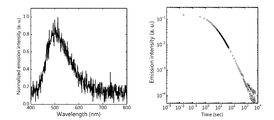
- the peak wavelength of the afterglow spectrum was 526 nm.
- a glassy film was formed in the same manner, changing the point using m-MTDATA or CV instead of TMB.
- the films using m-MTDATA and CV showed afterglow even after the irradiation was stopped.
- the results of examining the afterglow spectrum and the light emission lifetime characteristic of the film using m-MTDATA are shown in FIG. 3, and the results of examining the afterglow spectrum and the light emission lifetime characteristic of the film using CV are shown in FIG.
- the peak wavelength of the afterglow spectrum of the film using m-MTDATA was 523 nm, and the peak wavelength of the afterglow spectrum of the film using CV was 513 nm.
- TMB was mixed in an amount of 1 mol% to 98 mol% of PPT, mixed in an amount of 1 mol% of 4CzBN as a third compound, heated and melted, and then quenched to obtain a phosphorescent film.
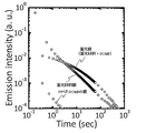
- the light emission life characteristics of a phosphorescent film containing TTPA, TBRb, and DCM2 are shown in FIG. 5 as representative light emission life characteristics.
- “OLPL” shows the combination of TMB / PPT in the figure.
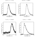
- the afterglow spectrum of a phosphorescent film containing TTPA, TBRb, DCM2, TBPe is shown in FIG.
- These afterglow spectra are clearly different from the afterglow spectrum of TMB / PPT, and the peak wavelength is also shifted to control the emission wavelength.
- E S1 (B) TTPA -E S1 (A) is a negative formula (1)
- the phosphorescent layer containing TBRB, DCM2 is achieved control to the long wavelength side
- E S1 (B) -E S1 The control to the short wavelength side was achieved in the luminous film containing TBPe in which (A) has a positive value of more than 0 and not more than 0.15 eV.
- the peak wavelength of the afterglow spectrum is the same as that of the TMB / PPT solution, and these third organic compounds from TMB / PPT It was confirmed that no energy transfer was made.
- the photoluminescence quantum yield (PL quantum yield) and afterglow time by 340 nm excitation light were measured about the luminous film produced in Example 1, 3, 4, 5 and the luminous film without a 3rd organic compound. .
- the results are shown in Table 2.
- the afterglow time is a time from when the irradiation of the excitation light is stopped until the light emission intensity becomes less than 3 pW.
- each of the phosphorescent films of the examples in which the third organic compound is added to the phosphorescent film has a higher photoluminescence quantum yield than the phosphorescent film without the third organic compound, and the afterglow Lasted a long time.
- the photoluminescence quantum yield 3.5 times and the afterglow time close to six times are achieved as compared with the phosphorescent film without the third organic compound. It was done. From this, it is understood that the luminous efficiency and the afterglow time are dramatically improved by adding the third organic compound to the phosphorescent film.
- TMB was mixed in an amount of 1 mol% with respect to 83 mol% of PPT, mixed in an amount of 16 mol% as a third compound DCM2, heated and melted, and then quenched to obtain a phosphorescent film.
- this luminous film was irradiated with excitation light of 340 nm, light emission with a peak wavelength of 711 nm was observed, and afterglow was observed from the luminous film even after the irradiation was stopped.
- the full width at half maximum (FWHM) of the emission peak was 134 nm. From this, it was found that by adding DCM 2 to the phosphorescent film at a high concentration, the emission wavelength becomes longer and near infrared emission can be realized.
- Comparative Example 5 Preparation of Films of PPT and TTPA
- a quartz substrate was heated to a temperature equal to or higher than the melting point of PPT (250 ° C. or more) to melt PPT on the quartz substrate.
- TTPA was added to the melt of PPT at a concentration of 1% by weight, mixed, and quenched to form a luminous material film in a glass state, and sealed with a glass substrate and an ultraviolet curable resin.
- Comparative Example 6 Preparation of Membrane of PPT and DCM 2 A membrane was prepared in the same manner as Comparative Example 1 except that DCM 2 was used instead of TTPA.
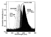
- Luminescent material film consisting of TMB and PPT Luminescent film consisting of TMB / PPT / TTPA prepared in Example 3
- emission spectrum of TTPA in toluene solution (10 -5 mol / L) with 340 nm excitation light and toluene solution of TTPA
- the light absorption spectrum of is shown in FIG. 7, and the light emission lifetimes of the luminous film, the luminous material film, and the PPT and TTPA films prepared in Comparative Example 5 are shown in FIG.
- Luminescent material film consisting of TMB and PPT
- Luminescent film consisting of TMB / PPT / TBRb prepared in Example 4
- emission spectrum of TBRb in toluene solution (10 -5 mol / L) by 340 nm excitation light and toluene solution of TBRb
- the light absorption spectrum of the phosphor is shown in FIG. 9, and the results of examining the light emission lifetimes of the phosphorescent film and the phosphorescent material film are shown in FIG.
- Luminescent material film composed of TMB and PPT Luminescent film composed of TMB / PPT / DCM2 prepared in Example 5
- FIG. 11 The light absorption spectrum of is shown in FIG. 11, and the light emission lifetimes of the luminous film, the luminous material film, and the PPT and DCM2 films prepared in Comparative Example 6 were examined, and the results are shown in FIG. In FIGS. 7, 9 and 11, dotted lines indicate light absorption spectra, and the other waveforms indicate emission spectra.
- the emission peak of the phosphorescent film containing the phosphorescent material and the third organic compound is shifted to a longer wavelength side than the emission peak of the phosphorescent material film or the toluene solution of the third organic compound.
- the phosphorescent material and the third organic compound in combination, an emission color having a longer wavelength which can not be obtained only by the phosphorescent material or the third organic compound can be obtained, and emission color control in a wide wavelength range is possible. It turned out that it would be possible. In particular, observation of red light emission with high color purity, which was difficult to realize with inorganic phosphorescent materials, is extremely revolutionary (see FIG. 11).
- FIG. 8, 10, 12 showed that the luminous film produced by each Example has a long lifetime and luminous intensity is also improved rather than a luminous material film.
- TBPe which is a green-blue light emitter
- DBP which is a red light emitter
- Example 10 to 13 In Examples 10 to 13, a phosphorescent material was used as the third organic compound. As for the phosphorescent material, since the lowest excited singlet energy level E S1 (B) can not be measured, the lowest excited triplet energy level E T1 (B) is used as an indicator of E S1 (B). In ordinary phosphorescent materials, E T1 (B) -E S1 (A) is less than -0.1 eV because the lowest excitation singlet energy level and the lowest excitation triplet energy level are not extremely separated. Preferably, if it is less than -0.3 eV, it can be considered that E S1 (B)-E S1 (A) ⁇ 0.15 eV.
- the luminous composition of the present invention is easy to control the light emission color, and can emit red light with high color purity which is difficult to realize by the conventional inorganic luminous material, and realizes white light. You can also. Therefore, according to the present invention, it is possible to realize a luminous material having various color combinations. Therefore, the luminous composition of the present invention has high industrial applicability.
Landscapes
- Chemical & Material Sciences (AREA)
- Engineering & Computer Science (AREA)
- Materials Engineering (AREA)
- Organic Chemistry (AREA)
- Physics & Mathematics (AREA)
- General Physics & Mathematics (AREA)
- Theoretical Computer Science (AREA)
- Life Sciences & Earth Sciences (AREA)
- Wood Science & Technology (AREA)
- Electroluminescent Light Sources (AREA)
- Optical Filters (AREA)
Abstract
第1有機化合物と第2有機化合物と第3有機化合物とを少なくとも含み、下記式(1)を満たす有機蓄光組成物は発光色制御が容易な蓄光材料である。ES1(A)は前記第1有機化合物と前記第2有機化合物からなる発光の最低励起一重項エネルギー準位を表し、ES1(B)は前記第3有機化合物の最低励起一重項エネルギー準位を表す。 式(1) ES1(B)- ES1(A) ≦ 0.15eV
Description
本発明は、発光波長制御が容易な蓄光組成物および蓄光素子に関する。また、本発明は蓄光材料の波長制御方法にも関する。
蓄光材料は、励起光が照射されている間にエネルギーを蓄え、励起光の照射が断たれた後にも、蓄えたエネルギーにより発光する発光材料である。蓄光材料は、暗所や夜間で光る時計の文字盤、標識や案内板等の文字、図形等のための夜光塗料に用いられており、最近では、電力供給がなくても照明できる蓄光照明への利用も進められている。
こうした蓄光材料の中でも、特に、発光時間が長い蓄光材料として、Eu、Ce、Tb等の希土類元素を含む無機塩が知られている(例えば、特許文献1参照)。
こうした蓄光材料の中でも、特に、発光時間が長い蓄光材料として、Eu、Ce、Tb等の希土類元素を含む無機塩が知られている(例えば、特許文献1参照)。
しかしながら、これらの無機塩からなる蓄光材料(無機蓄光材料)は、希土類元素を含むこと、高温プロセスが必要である、溶媒に不溶であるといった欠点がある。そこで本発明者らは有機材料を用いて発光波長を制御可能な蓄光材料系を提供することを目的として鋭意検討を進めた。
鋭意検討を進めた結果、本発明者らは、第1有機化合物と第2有機化合物からなる蓄光材料に、所定の条件を満たす第3有機化合物を添加することにより、蓄光発光色を制御できることを見出した。本発明は、このような知見に基づいて提案されたものであり、以下の構成を有する。
[1] 第1有機化合物と第2有機化合物と第3有機化合物とを少なくとも含み、下記式(1)を満たす有機蓄光組成物。
式(1) ES1(B)- ES1(A) ≦ 0.15eV
(上式において、ES1(A)は前記第1有機化合物と前記第2有機化合物からなる発光の最低励起一重項エネルギー準位を表し、ES1(B)は前記第3有機化合物の最低励起一重項エネルギー準位を表す。ES1(A)とES1(B)の単位はeVである。)
[2] 下記式(2)を満たす、[1]に記載の蓄光組成物。
式(2) 0eV < ES1(B)- ES1(A) ≦ 0.15eV
[3] 下記式(3)を満たす、[1]に記載の蓄光組成物。
式(3) ES1(B)- ES1(A) < 0eV
[4] 前記第1有機化合物と前記第2有機化合物からなる組成物が蓄光材料である、[1]~[3]のいずれか1項に記載の蓄光組成物。
[5] 前記蓄光組成物への光照射により、前記第1有機化合物と前記第2有機化合物がエキサイプレックスを形成する、[1]~[4]のいずれか1項に記載の蓄光組成物。
[6]前記第1有機化合物が電子ドナー性化合物であり、前記第2有機化合物が電子アクセプター性化合物である、[1]~[5]のいずれか1項に記載の蓄光組成物。
[7] 前記第3有機化合物が凝集体を形成している、[1]~[6]のいずれか1項に記載の蓄光組成物。
[8] 前記凝集体がエキシマーである、[7]に記載の蓄光組成物。
[9] 前記第3有機化合物が蛍光材料である、[1]~[8]のいずれか1項に記載の蓄光組成物。
[10] [1]~[9]のいずれか1項に記載の蓄光組成物を支持体上に有する蓄光素子。
[11] 第1有機化合物と第2有機化合物を含む蓄光材料の発光波長を制御する方法であって、
前記蓄光材料に、下記式(1)を満たす第3有機化合物を添加することを特徴とする波長制御方法。
式(1) ES1(B)- ES1(A) ≦ 0.15eV
(上式において、ES1(A)は前記第1有機化合物と前記第2有機化合物からなる発光の最低励起一重項エネルギー準位を表し、ES1(B)は前記第3有機化合物の最低励起一重項エネルギー準位を表す。ES1(A)とES1(B)の単位はeVである。)
[12] 前記第3有機化合物が下記式(2)を満たす、[11]に記載の波長制御方法。
式(2) 0eV < ES1(B)- ES1(A) ≦ 0.15eV
[13] 前記第3化合物を添加することにより、蓄光材料の発光波長を短波長側に制御する、[12]に記載の波長制御方法。
[14] 前記第3有機化合物が下記式(3)を満たす、[11]に記載の波長制御方法。
式(3) ES1(B)- ES1(A) < 0eV
[15] 前記第3化合物を添加することにより、蓄光材料の発光波長を長波長側に制御する、[14]に記載の波長制御方法。
式(1) ES1(B)- ES1(A) ≦ 0.15eV
(上式において、ES1(A)は前記第1有機化合物と前記第2有機化合物からなる発光の最低励起一重項エネルギー準位を表し、ES1(B)は前記第3有機化合物の最低励起一重項エネルギー準位を表す。ES1(A)とES1(B)の単位はeVである。)
[2] 下記式(2)を満たす、[1]に記載の蓄光組成物。
式(2) 0eV < ES1(B)- ES1(A) ≦ 0.15eV
[3] 下記式(3)を満たす、[1]に記載の蓄光組成物。
式(3) ES1(B)- ES1(A) < 0eV
[4] 前記第1有機化合物と前記第2有機化合物からなる組成物が蓄光材料である、[1]~[3]のいずれか1項に記載の蓄光組成物。
[5] 前記蓄光組成物への光照射により、前記第1有機化合物と前記第2有機化合物がエキサイプレックスを形成する、[1]~[4]のいずれか1項に記載の蓄光組成物。
[6]前記第1有機化合物が電子ドナー性化合物であり、前記第2有機化合物が電子アクセプター性化合物である、[1]~[5]のいずれか1項に記載の蓄光組成物。
[7] 前記第3有機化合物が凝集体を形成している、[1]~[6]のいずれか1項に記載の蓄光組成物。
[8] 前記凝集体がエキシマーである、[7]に記載の蓄光組成物。
[9] 前記第3有機化合物が蛍光材料である、[1]~[8]のいずれか1項に記載の蓄光組成物。
[10] [1]~[9]のいずれか1項に記載の蓄光組成物を支持体上に有する蓄光素子。
[11] 第1有機化合物と第2有機化合物を含む蓄光材料の発光波長を制御する方法であって、
前記蓄光材料に、下記式(1)を満たす第3有機化合物を添加することを特徴とする波長制御方法。
式(1) ES1(B)- ES1(A) ≦ 0.15eV
(上式において、ES1(A)は前記第1有機化合物と前記第2有機化合物からなる発光の最低励起一重項エネルギー準位を表し、ES1(B)は前記第3有機化合物の最低励起一重項エネルギー準位を表す。ES1(A)とES1(B)の単位はeVである。)
[12] 前記第3有機化合物が下記式(2)を満たす、[11]に記載の波長制御方法。
式(2) 0eV < ES1(B)- ES1(A) ≦ 0.15eV
[13] 前記第3化合物を添加することにより、蓄光材料の発光波長を短波長側に制御する、[12]に記載の波長制御方法。
[14] 前記第3有機化合物が下記式(3)を満たす、[11]に記載の波長制御方法。
式(3) ES1(B)- ES1(A) < 0eV
[15] 前記第3化合物を添加することにより、蓄光材料の発光波長を長波長側に制御する、[14]に記載の波長制御方法。
本発明によれば、蓄光材料の発光波長を容易に制御することができる。また、従来の無機蓄光材料では実現することが困難であった赤色光を高い色純度で発光することができ、また白色光を実現することもできる。
以下において、本発明の内容について詳細に説明する。以下に記載する構成要件の説明は、本発明の代表的な実施態様や具体例に基づいてなされることがあるが、本発明はそのような実施態様や具体例に限定されるものではない。なお、本明細書において「~」を用いて表される数値範囲は、「~」の前後に記載される数値を下限値および上限値として含む範囲を意味する。また、本発明に用いられる化合物の分子内に存在する水素原子の同位体種は特に限定されず、例えば分子内の水素原子がすべて1Hであってもよいし、一部または全部が2H(デューテリウムD)であってもよい。
本明細書における「室温」とは20℃のことを意味する。
本明細書における「励起光」とは、測定対象物に励起を引き起こして発光を生じさせる光であり、その測定対象物の吸収波長に一致する波長の光を用いることができる。
本明細書における「電子求引基」とはハメットのσp値が正である置換基を意味し、「電子供与基」とはハメットのσp値が負である置換基を意味する。ハメットのσp値に関する説明と各置換基の数値については、Hansch,C.et.al.,Chem.Rev.,91,165-195(1991)のσp値に関する記載を参照することができる。
本明細書における「室温」とは20℃のことを意味する。
本明細書における「励起光」とは、測定対象物に励起を引き起こして発光を生じさせる光であり、その測定対象物の吸収波長に一致する波長の光を用いることができる。
本明細書における「電子求引基」とはハメットのσp値が正である置換基を意味し、「電子供与基」とはハメットのσp値が負である置換基を意味する。ハメットのσp値に関する説明と各置換基の数値については、Hansch,C.et.al.,Chem.Rev.,91,165-195(1991)のσp値に関する記載を参照することができる。
[蓄光組成物]
本発明の蓄光組成物は、第1有機化合物と第2有機化合物と第3有機化合物を少なくとも含有する。また、本発明の蓄光組成物は下記式(1)を満たす。
式(1) ES1(B)- ES1(A) ≦ 0.15eV
式(1)において、ES1(A)は前記第1有機化合物と前記第2有機化合物からなる発光の最低励起一重項エネルギー準位を表し、ES1(B)は前記第3有機化合物の最低励起一重項エネルギー準位を表す。ES1(A)とES1(B)の単位はeVである。
本発明によれば、第1有機化合物と第2有機化合物により形成される蓄光材料に、式(1)の関係を満たす第3有機化合物を使用することにより、蓄光材料の発光波長を容易に制御することができる。例えば、下記式(2)を満たすような第3有機化合物を使用すれば、蓄光材料の発光波長を短波長側に比較的容易に制御することが可能である。
式(2) 0eV < ES1(B)- ES1(A) ≦ 0.15eV
また、例えば下記式(3)を満たすような第3有機化合物を使用すれば、蓄光材料の発光波長を長波長側に比較的容易に制御することが可能である。それによって、例えば色純度が高い赤色発光を実現することができる。
式(3) ES1(B)- ES1(A) < 0eV
したがって、第1有機化合物と第2有機化合物を含む蓄光材料に、適切な第3有機化合物を使用することにより、所望の発光波長に制御された蓄光組成物を提供することができる。また、第3有機化合物を適宜選択することにより、多様な色味を有する蓄光組成物を提供することができる。
第1有機化合物と第2有機化合物を含む蓄光材料に第3有機化合物をさらに使用することにより制御される発光波長シフト幅は、例えば5nm以上、10nm以上、20nm以上、40nm以上、70nm以上、100nm以上、130nm以上にすることが可能である。また、第1有機化合物と第2有機化合物を含む蓄光材料に第3有機化合物をさらに使用することにより制御される発光波長シフト幅は、例えば300nm以下、200nm以下、150nm以下とすることが可能である。このような波長制御は、第1有機化合物と第2有機化合物を含む蓄光材料から、第3有機化合物へのエネルギー移動が生じることにより実現される。なお、ここでいう波長制御幅は、ピーク波長のシフト幅を意味する。
なお、ES1(B)- ES1(A)の値は、例えば-0.1eV以下、-0.2eV以下、-0.3eV以下、-0.4eV以下、-0.5eV以下、-0.6eV以下の領域から選択することも可能である。
本発明における「第1有機化合物」は、蓄光組成物への光照射に伴って、電子を放出してラジカルカチオン状態になる分子であり、本発明における「第2有機化合物」は、第1有機化合物が放出した電子を受け取ってラジカルアニオン状態になる分子であることが好ましい。「ラジカルカチオン」や「ラジカルアニオン」といったラジカルの存在は、ESR(Electron Spin Resonance)測定等により確認することができる。
本発明における「蓄光材料」は、こうした第1有機化合物と第2有機化合物を含む材料であって、光照射により発光し、その光照射を停止した後にも発光が継続するものである。ここで、本明細書中では、光照射を停止した時点からの発光を「残光」と言い、光照射を停止した時点から発光強度が検出できなくなるまでの時間を「残光時間」と言うことがある。本願でいう蓄光材料は残光時間が0.1秒以上の蓄光材料を意味し、本発明の蓄光材料の残光時間は1秒以上であることが好ましく、5秒以上であることがより好ましく、5分以上であることがさらに好ましく、20分以上であることがさらにより好ましい。
発光強度は、例えば分光測定装置(浜松ホトニクス社製:PMA-50)を用いて測定することができる。0.01mcd/m2未満の発光は、発光強度が検出できないとみなすことができる。
第1有機化合物と第2有機化合物を含む蓄光材料は、第3有機化合物を添加することにより、その発光波長を制御することができる。本発明では、このような第1有機化合物と第2有機化合物と第3有機化合物を含む組成物を「蓄光組成物」と呼ぶ。
本発明の蓄光組成物の発光は、図1の模式図で示す発光メカニズムで生じるものと推測される。以下において、この蓄光組成物の発光メカニズムについて説明する。図1において、(a)は蓄光組成物における電子の移動過程を表し、(b)は蓄光組成物におけるエネルギー状態の遷移過程を表す。図1(c)は、第3有機化合物がトラップ機能を有する場合の電子の移動過程を平面視で表したものである。図1(c)の各図において、左側列の黒枠で囲った領域は第1有機化合物を表し、中央列の黒枠で囲った領域は第3有機化合物を表し、その他の領域は第2有機化合物を表す。なお、図1(c)に示した第3有機化合物の電子トラップによる電荷蓄積状態は、本発明では必須の過程ではない。また、以下の説明における丸括弧付きローマ数字は、図1中の丸括弧付きローマ数字に対応しており、各発光過程の順位を表す。ただし、本発明の蓄光組成物の発光メカニズムは、以下で説明する発光メカニズムによって限定的に解釈されるべきものではない。
まず、蓄光組成物に光が照射されると、図1(a)に示すように、第2有機化合物が光を吸収して、そのHOMO(Highest Occupied Molecular Orbital)からLUMO(Lowest Unoccupied Molecular Orbital)へ電子が遷移し(i)、その第2有機化合物のHOMOへ、第1有機化合物のHOMOから電子が移動する(ii)。もしくは、第1有機化合物のHOMOから第2有機化合物のLUMOへの光吸収による直接電子遷移がおきる。その結果、HOMOにホールが生じた第1有機化合物(ラジカルカチオン状態の第1有機化合物)とLUMOに余分な電子が入った第2有機化合物(ラジカルアニオン状態の第2有機化合物)からなる電荷移動状態が生成する。第2有機化合物のLUMOに入った電子は、その第2有機化合物から分離して近接する第2有機化合物のLUMOへ順次移動して拡散する(iii)。そして、第3有機化合物に近接する第2有機化合物のLUMOに電子が入ると、その電子が第3有機化合物のLUMOに移動した後、第1有機化合物のホールと再結合する。この再結合エネルギーにより、第1有機化合物と第2有機化合物が会合してエキサイプレックス(励起状態)が形成される。
図1(b)に示すように、この励起状態における励起一重項状態S1と励起三重項状態T1の発生確率は25%:75%であり、これらの励起状態が基底状態に戻る際に光が放射される(v)。この光の放射経路として、次の(ア)~(オ)の経路が考えられる。すなわち、蓄光材料において、(ア)励起一重項状態S1が基底状態へ戻る際に蛍光が放射され、(イ)励起三重項状態T1が基底状態へ戻る際に燐光が放射される。また、(ウ)励起三重項状態T1から励起一重項状態S1への逆項間交差が生じ、その励起一重項状態S1が基底状態へ戻る際に蛍光(遅延蛍光)が放射される。さらに、また(エ)励起一重項状態S1から励起三重項状態T1への項間交差が生じ、その励起三重項状態T1が基底状態へ戻る際に燐光が放射される。そして、(オ)第3有機化合物が蛍光材料である場合には、蓄光材料の励起一重項状態S1のエネルギーが、フェルスター移動機構(FRET)あるいはデクスターエネルギー移動により第3有機化合物に移動して第3有機化合物が励起一重項状態S1へ遷移し、この励起一重項状態S1が基底状態へ戻る際に蛍光が放射される。
以上の発光メカニズムにおいて、蓄光材料がエキサイプレックスを形成して発光するものであることは、その蓄光材料の発光スペクトルが、第1有機化合物単独で観測される発光スペクトル、および、第2有機化合物単独で観測される発光スペクトルとは異なるパターンであることをもって確認することができる。発光スペクトルのパターンが異なる例として、発光極大波長が異なる場合、発光ピークの半値幅や立ち上がりの傾きが異なる場合、発光ピークの数が異なる場合を挙げることができる。こうしたエキサイプレックスによる発光では、第1有機化合物と第2有機化合物が空間的に離れていることに起因して、最低励起一重項エネルギー準位と最低励起三重項エネルギー準位との差ΔESTが極めて小さく、励起三重項状態T1から励起一重項状態S1への逆項間交差が生じ易い。これにより、励起三重項状態T1のエネルギーも蛍光発光に有効に利用することができ、高い発光効率を得ることができる。ここで、この逆項間交差を経て放射される蛍光は、基底状態から直接遷移した励起一重項状態S1からの蛍光よりも遅れて観測される蛍光であり、本明細書中では「遅延蛍光」と称する。
また、上記のように、蓄光材料における発光経路には(ア)~(オ)の経路が挙げられるが、蓄光材料の発光は(ア)~(オ)のうちの少なくとも1つの経路で行われればよく、(ア)~(オ)のいずれかの1つの経路で発光してもよいし、(ア)~(オ)のうちの2つ以上の組み合わせで発光してもよい。
また、第3有機化合物は、それぞれの分子が独立した単量体の状態(凝集していない状態)で発光してもよいし、励起された第3有機化合物の分子同士が凝集してエキシマーを形成し、このエキシマーの状態で発光してもよい。エキシマーの状態で発光した光は、凝集していない状態で発光した光よりも波長が長い傾向がある。そのため、こうしたエキシマーからの発光を用いることにより、蓄光組成物の発光色を、より容易に長波長側へ発光色制御できるようになる。
また、ここでは第3有機化合物が蛍光材料である場合を例にして発光メカニズムを説明したが、第3有機化合物として燐光材料や遅延蛍光材料を用いる場合にも、同様のメカニズムで発光が生じる。ここで、(オ)の代わりの経路として、第3有機化合物が燐光材料である場合には、蓄光材料からデクスター移動機構で移動してきた励起三重項エネルギーにより、第3有機化合物が励起三重項状態T1に遷移し、その励起三重項状態T1が基底状態へ戻る際に燐光が放射される。また、第3有機化合物が遅延蛍光材料である場合には、蓄光材料からデクスター移動機構で移動してきた励起三重項エネルギーにより、第3有機化合物が励起三重項状態T1に遷移した後、励起三重項状態T1から励起一重項状態T1への逆項間交差が生じる。この励起一重項状態S1が基底状態へ戻る際に蛍光が放射される。
また、図1(c)に示すように、(i)光吸収、(ii)電荷移動状態および(iii)電荷分離状態を経て第2の有機化合物から電子を受け渡された第3有機化合物は、その電子を一旦捕捉して蓄積した後に熱活性化等により電子を放出して第2有機化合物へ該電子を戻す、トラップ機能(電子トラップ-脱電子トラップ機能)を奏してもよい。この場合、第3有機化合物から第2有機化合物へ受け渡された電子は第2有機化合物同士の間を移動して第1有機化合物のホールと再結合する(iv)。この電荷再結合により、第1有機化合物と第2有機化合物の間にエキサイプレックスが形成されて、上記の(ア)~(エ)の径路で発光が生じる。さらに、また(オ)エキサイプレックスの励起エネルギーが、フェルスター移動機構(FRET)あるいはデクスター移動機構により第3有機化合物に移動して第3有機化合物が発光する。こうした経路の発光では、第3有機化合物が電子を一旦捕捉する過程と、その後の第2有機化合物間の電子移動の過程が加わるため、より残光時間が長くなるという効果が得られる。
次に、この蓄光組成物が含有する蓄光材料(第1有機化合物と第2有機化合物)および第3有機化合物、必要に応じて添加されるその他の成分について説明する。
[蓄光材料]
本発明の蓄光組成物が含有する蓄光材料は、第1有機化合物と第2有機化合物を含むものであり、第1有機化合物と第2有機化合物のみからなるものであってもよい。
蓄光材料の発光波長は、特に制限されないが、200~2000nmであることが好ましい。例えば、400nm以上、600nm以上、800nm以上、1000nm以上、1200nm以上の波長領域から選択してもよいし、1500nm以下、1100nm以下、900nm以下、700nm以下、500nm以下の領域から選択してもよい。
以下において、蓄光材料を構成する第2有機化合物および第1有機化合物について説明する。
本発明の蓄光組成物が含有する蓄光材料は、第1有機化合物と第2有機化合物を含むものであり、第1有機化合物と第2有機化合物のみからなるものであってもよい。
蓄光材料の発光波長は、特に制限されないが、200~2000nmであることが好ましい。例えば、400nm以上、600nm以上、800nm以上、1000nm以上、1200nm以上の波長領域から選択してもよいし、1500nm以下、1100nm以下、900nm以下、700nm以下、500nm以下の領域から選択してもよい。
以下において、蓄光材料を構成する第2有機化合物および第1有機化合物について説明する。
(第1有機化合物)
蓄光材料を構成する第1有機化合物は、第2有機化合物と協働して残光放射を実現しうるものであり、電子ドナー化合物であることが好ましい。ここでいう電子ドナー化合物は、第2有機化合物に対して電子を放出しやすい化合物であることを意味する。そして、第1有機化合物は、第2有機化合物とエキサイプレックスを形成して発光するものであることが好ましい。また、第1有機化合物は、ラジカルカチオン状態が安定であり、第2有機化合物と組み合わせて蓄光材料を構成したとき、10Kで(および好ましくは20℃においても)残光が放射されるものであることも好ましい。これにより、より発光寿命が長い蓄光組成物を得ることができる。
第1有機化合物のHOMOは第2有機化合物のHOMOよりも高く、そのLUMOが第2有機化合物のLUMOよりも高いことが好ましい。これにより、第1有機化合物のHOMOから第2有機化合物のHOMOまたはLUMOへの電子移動が生じ易くなり、電荷分離状態を効率よく生成することができる。具体的には、第1有機化合物のHOMOは、-3.5~-8.0eVであることが好ましく、-4.0~-7.0eVであることがより好ましく、-4.5~-6.0eVであることがさらに好ましい。
第1有機化合物のHOMOは光電子分光法またはサイクリックボルタンメトリーにより測定することができ、またLUMOはサイクリックボルタンメトリーまたは吸収スペクトルより求めることができる。
第1有機化合物には、ラジカルカチオンの安定性の点から、電子供与基を有する化合物を用いることが好ましく、電子供与基と共役系を有する化合物を用いることがより好ましく、ジアルキルアミノ基と芳香環を有する化合物を用いることがさらに好ましい。また、第1有機化合物は、希土類原子および金属原子を含まないことが好ましく、炭素、水素、窒素、酸素、硫黄、リンから選択される原子のみから構成されることがより好ましい。
第1有機化合物がジアルキルアミノ基と芳香環を有する化合物である場合、その芳香環は、芳香族炭化水素であってもよいし、芳香族複素環であってもよいが、芳香族炭化水素であることが好ましい。芳香族炭化水素の説明と好ましい範囲については、上記のAr15およびAr16が置換もしくは無置換のアリーレン基であるときのアリーレン基を構成する芳香環についての説明と好ましい範囲を参照することができる。また、芳香族複素環の説明と好ましい範囲については、上記のAr15およびAr16が置換もしくは無置換のヘテロアリーレン基であるときのヘテロアリーレン基を構成する複素環についての説明と好ましい範囲を参照することができる。これらの中で、芳香環はベンゼン環、ビフェニル環であることが好ましく、ビフェニル環であることがより好ましい。芳香環は置換基で置換されていてもよい。芳香環に置換しうる置換基の具体例と好ましい範囲については、上記のAr15およびAr16におけるアリーレン基等に置換しうる置換基の具体例と好ましい範囲を参照することができる。一方、ジアルキルアミノ基は芳香環に置換していることが好ましい。第1有機化合物が含むジアルキルアミノ基の数は、1つであってもよいし、2つ以上であってもよいが、1~4つであることが好ましく、2つまたは4つであることがより好ましく、2つであることがさらに好ましい。ジアルキルアミノ基のアルキル基の説明と好ましい範囲、具体例については、下記のR21等におけるアルキル基についての説明と好ましい範囲、具体例を参照することができる。ジアルキルアミノ基のアルキル基は置換基で置換されていてもよい。その置換基の説明と好ましい範囲については、R21等におけるアルキル基に置換しうる置換基についての説明と好ましい範囲を参照することができる。
第1有機化合物は、下記一般式(1)で表される化合物であることが好ましい。

一般式(1)において、Ar21は置換もしくは無置換のアリーレン基を表す。Ar21のアリーレン基を構成する芳香環の説明と好ましい範囲、アリーレン基の具体例については、上記のAr15およびAr16が置換もしくは無置換のアリーレン基であるときのアリーレン基を構成する芳香環についての説明と好ましい範囲、アリーレン基の具体例を参照することができる。Ar21は置換もしくは無置換のフェニレン基、置換もしくは無置換のビフェニルジイル基であることが好ましく、置換もしくは無置換のビフェニルジイル基であることがより好ましい。アリーレン基に置換しうる置換基の具体例と好ましい範囲については、上記のAr15およびAr16におけるアリーレン基等に置換しうる置換基の具体例と好ましい範囲を参照することができる。
R21~R24は各々独立に置換もしくは無置換のアルキル基を表す。R21~R24は互いに同一であっても異なっていてもよい。R21~R24におけるアルキル基は、直鎖状、分枝状、環状のいずれであってもよい。好ましい炭素数は1~20であり、より好ましくは1~10であり、さらに好ましくは1~6である。例えば、メチル基、エチル基、n-プロピル基、イソプロピル基などを例示することができる。アルキル基に置換しうる置換基として、炭素数6~40のアリール基、炭素数3~40のヘテロアリール基、炭素数2~10のアルケニル基、炭素数2~10のアルキニル基等を挙げることができる。これらの置換基は、さらに置換基で置換されていてもよい。
以下において、第1有機化合物として用いることができる好ましい化合物を挙げる。ただし、本発明において用いることができる第1有機化合物はこれらの具体例によって限定的に解釈されるべきものではない。

また、本発明で用いる第1有機化合物は、単体である第1有機化合物に重合性基を導入し、これをモノマーとして重合した重合体であってもよい。第1有機化合物として用いることができる重合体の具体例として、下記構造を有する重合体を挙げることができる。下記式において、nは1以上の整数である。ただし、本発明において第1有機化合物として用いることができる重合体はこの具体例によって限定的に解釈されるべきものではない。

(第1有機化合物の含有量)
蓄光材料における第1有機化合物の含有量は、第1有機化合物と第2有機化合物の合計モル数に対して60mol%未満であることが好ましく、30mol%未満であることがより好ましく、20mol%未満であることがさらに好ましく、10mol%未満であることがさらにより好ましい。また、蓄光材料における第1有機化合物の含有量は、第1有機化合物と第2有機化合物の合計モル数に対して0.001mol%超であることが好ましく、0.01mol%超であることがより好ましく、1mol%超であることがさらに好ましい。第1有機化合物の含有量を変えることにより、蓄光組成物が発光する発光色を制御することができる。例えば、第1有機化合物の含有量を多くする程、エキサイプレックス形成が強くなり長波長の発光になるという現象が見られる。こうした現象を利用することで、蓄光組成物の発光色や発光時間を制御することができる。例えば、下記の第2有機化合物(左側)と第1有機化合物(右側)からなる蓄光材料では、第1有機化合物の含有量が30mol%未満である場合には青色光を観測することができ、第1有機化合物の含有量が30mol%超である場合には黄色光が観測される。
蓄光材料における第1有機化合物の含有量は、第1有機化合物と第2有機化合物の合計モル数に対して60mol%未満であることが好ましく、30mol%未満であることがより好ましく、20mol%未満であることがさらに好ましく、10mol%未満であることがさらにより好ましい。また、蓄光材料における第1有機化合物の含有量は、第1有機化合物と第2有機化合物の合計モル数に対して0.001mol%超であることが好ましく、0.01mol%超であることがより好ましく、1mol%超であることがさらに好ましい。第1有機化合物の含有量を変えることにより、蓄光組成物が発光する発光色を制御することができる。例えば、第1有機化合物の含有量を多くする程、エキサイプレックス形成が強くなり長波長の発光になるという現象が見られる。こうした現象を利用することで、蓄光組成物の発光色や発光時間を制御することができる。例えば、下記の第2有機化合物(左側)と第1有機化合物(右側)からなる蓄光材料では、第1有機化合物の含有量が30mol%未満である場合には青色光を観測することができ、第1有機化合物の含有量が30mol%超である場合には黄色光が観測される。

(第2有機化合物)
蓄光材料を構成する第2有機化合物は、第1有機化合物と協働して残光放射を実現しうるものであり、電子アクセプター化合物であることが好ましい。ここでいう電子アクセプター化合物は、第1有機化合物から電子を受け取りやすい化合物であることを意味する。そして、第2有機化合物は、第1有機化合物とエキサイプレックスを形成して発光するものであることが好ましい。また、第2有機化合物は、ラジカルアニオン状態が安定であり、第1有機化合物と組み合わせて蓄光材料を構成したとき、10Kで(および好ましくは20℃においても)残光が放射されるものであることも好ましい。これにより、より発光寿命が長い蓄光組成物を得ることができる。
第2有機化合物のHOMOとLUMOのギャップは1.0~3.5eVであることが好ましく、1.5~3.4eVであることがより好ましく、2.0~3.3eVであることがさらに好ましい。これにより、蓄光組成物への光照射に伴って、そのHOMOからLUMOへの電子遷移を効率よく生じさせることができる。また、第2有機化合物のLUMOは6.0eV以下であることが好ましく、5.5eV以下あることがより好ましく、5.0eV以下であることがさらに好ましい。これにより、電荷分離状態が生成した後、第2有機化合物のLUMOからLUMOに亘って電子が移動し易く、ホールとの再結合を高い確率で発生させることができる。
第2有機化合物のHOMOは光電子分光法またはサイクリックボルタンメトリーにより測定することができ、またLUMOはサイクリックボルタンメトリーまたは吸収スペクトルより求めることができる。
また、第2有機化合物は、室温においてガラス状態で存在しうるように、高いガラス転移温度Tgを有するものであることが好ましく、また、成膜したときに高い膜密度が得られるものであることが好ましい。膜における第2有機化合物の密度が高いことにより、電荷分離状態が生成した後、第2有機化合物のLUMOからLUMOに亘って電子が拡散し易く、電子とホールの再結合を高い確率で発生させることができる。
第2有機化合物には、ラジカルアニオンの安定性の点から、電気陰性度が高い原子や電子求引基を有する化合物を用いることが好ましく、電気陰性度が高い原子や電子求引基と共役系を有する化合物を用いることがより好ましい。また、第2有機化合物は、希土類原子および金属原子を含まないことが好ましく、炭素、水素、窒素、酸素、硫黄、リンから選択される原子のみから構成されることがより好ましい。
第2有機化合物の好ましい例として、ホスフィンオキシド構造R3P(=O)(Rは置換基を表し、3つのR同士は、互いに同一であっても異なっていてもよい)を1つ以上含む化合物を挙げることができ、さらに好ましい例として、ホスフィンオキシド構造R3P(=O)を1つ以上と、それ以外にヘテロ原子を1つ以上含む化合物を挙げることができる。ヘテロ原子としては、N、O、S、P等を挙げることができ、このうちの1種のみを含んでいてもよいし、2種以上を含んでいてもよい。第2有機化合物が含むホスフィンオキシド構造の数は2つ以上であることが好ましく、その場合、複数のホスフィンオキシド構造は互いに同一であっても異なっていてもよい。また、複数のホスフィンオキシド構造は、その置換基Rの少なくとも1つが他のホスフィンオキシド構造の置換基Rにヘテロ原子を介して連結していることが好ましく、その置換基Rの少なくとも1つが他のホスフィンオキシド構造の置換基Rにヘテロ原子を介して連結するとともに、その連結している置換基Rのヘテロ原子に結合している原子とは別の原子同士が互いに単結合で連結していることがより好ましい。
ホスフィンオキシド構造の置換基Rは、置換もしくは無置換のアリール基、置換もしくは無置換のヘテロアリール基であることが好ましい。アリール基を構成する芳香環の説明と好ましい範囲、アリール基の具体例については、下記のAr11等が置換もしくは無置換のアリール基であるときのアリール基を構成する芳香環についての説明と好ましい範囲、アリール基の具体例を参照することができる。ヘテロアリール基を構成する複素環の説明と好ましい範囲、ヘテロアリール基の具体例については、下記のAr11等が置換もしくは無置換のヘテロアリール基であるときのヘテロアリール基を構成する複素環についての説明と好ましい範囲、ヘテロアリール基の具体例を参照することができる。アリール基およびヘテロアリール基に置換しうる置換基の具体例と好ましい範囲については、Ar11等におけるアリール基およびヘテロアリール基に置換しうる置換基の具体例と好ましい範囲を参照することができる。
ホスフィンオキシド構造の置換基Rは、置換もしくは無置換のアリール基、置換もしくは無置換のヘテロアリール基であることが好ましい。アリール基を構成する芳香環の説明と好ましい範囲、アリール基の具体例については、下記のAr11等が置換もしくは無置換のアリール基であるときのアリール基を構成する芳香環についての説明と好ましい範囲、アリール基の具体例を参照することができる。ヘテロアリール基を構成する複素環の説明と好ましい範囲、ヘテロアリール基の具体例については、下記のAr11等が置換もしくは無置換のヘテロアリール基であるときのヘテロアリール基を構成する複素環についての説明と好ましい範囲、ヘテロアリール基の具体例を参照することができる。アリール基およびヘテロアリール基に置換しうる置換基の具体例と好ましい範囲については、Ar11等におけるアリール基およびヘテロアリール基に置換しうる置換基の具体例と好ましい範囲を参照することができる。
第2有機化合物は、下記一般式(2)で表される化合物であることが好ましい。

一般式(2)において、Ar11~Ar14は各々独立に置換もしくは無置換のアリール基または置換もしくは無置換のヘテロアリール基を表し、置換もしくは無置換のアリール基であることが好ましい。Ar11~Ar14は互いに同一であっても異なっていてもよい。Ar15およびAr16は各々独立に置換もしくは無置換のアリーレン基または置換もしくは無置換のヘテロアリーレン基を表し、Ar15とAr16は互いに単結合で連結して縮環構造を形成していてもよい。Ar15およびAr16は互いに同一であっても異なっていてもよい。Ar15およびAr16は置換もしくは無置換のアリーレン基であることが好ましく、そのアリーレン基同士が、互いに単結合で連結して縮環構造を形成していることがより好ましい。
Ar11~Ar14が置換もしくは無置換のアリール基であるときのアリール基を構成する芳香環、並びに、Ar15およびAr16が置換もしくは無置換のアリーレン基であるときのアリーレン基を構成する芳香環は、単環であっても、2以上の芳香環が縮合した縮合環であっても、2以上の芳香環が連結した連結環であってもよい。2以上の芳香環が連結している場合は、直鎖状に連結したものであってもよいし、分枝状に連結したものであってもよい。アリール基およびアリーレン基を構成する芳香環の炭素数は、6~40であることが好ましく、6~22であることがより好ましく、6~18であることがさらに好ましく、6~14であることがさらにより好ましく、6~10であることが特に好ましい。アリール基の具体例として、フェニル基、ナフタレニル基、ビフェニル基を挙げることができる。アリーレン基の具体例として、フェニレン基、ナフタレンジイル基、ビフェニルジイル基を挙げることができる。これらの中で、Ar11~Ar14として特に好ましいのは、置換もしくは無置換のフェニル基である。また、Ar15およびAr16として特に好ましいのは、置換もしくは無置換のフェニレン基であり、そのフェニレン基同士が互いに単結合で連結して3環構造(ベンゼン環とX11を含む5員環とベンゼン環の3環構造)を形成していることが特により好ましい。
Ar11~Ar14が置換もしくは無置換のヘテロアリール基であるときのヘテロアリール基を構成する複素環、並びに、Ar15およびAr16が置換もしくは無置換のヘテロアリーレン基であるときのヘテロアリーレン基を構成する複素環は、単環であっても、1以上の複素環と芳香環または複素環が縮合した縮合環であっても、1以上の複素環と芳香環または複素環が連結した連結環であってもよい。ヘテロアリール基を構成する複素環の炭素数は3~40であることが好ましく、5~22であることがより好ましく、5~18であることがさらに好ましく、5~14であることがさらにより好ましく、5~10であることが特に好ましい。複素環を構成する複素原子は窒素原子であることが好ましい。複素環の具体例として、ピリジン環、ピリダジン環、ピリミジン環、トリアゾール環、ベンゾトリアゾール環を挙げることができる。
Ar11~Ar14におけるアリール基およびヘテロアリール基に置換しうる置換基、Ar15およびAr16におけるアリーレン基およびヘテロアリーレン基に置換しうる置換基として、例えばヒドロキシ基、ハロゲン原子、炭素数1~20のアルキル基、炭素数1~20のアルコキシ基、炭素数1~20のアルキルチオ基、炭素数1~20のアルキル置換アミノ基、炭素数1~20のアリール置換アミノ基、炭素数6~40のアリール基、炭素数3~40のヘテロアリール基、炭素数2~10のアルケニル基、炭素数2~10のアルキニル基、炭素数2~20のアルキルアミド基、炭素数7~21のアリールアミド基、炭素数3~20のトリアルキルシリル基等が挙げられる。これらの具体例のうち、さらに置換基により置換可能なものは置換されていてもよい。より好ましい置換基は、炭素数1~20のアルキル基、炭素数1~20のアルコキシ基、炭素数1~20のアルキルチオ基、炭素数1~20のアルキル置換アミノ基、炭素数1~20のアリール置換アミノ基、炭素数6~40のアリール基、炭素数3~40のヘテロアリール基である。
X11はNR11、OまたはSを表し、R11は水素原子または置換基を表す。R11がとりうる置換基として、例えば炭素数1~20のアルキル基、炭素数6~40のアリール基、炭素数3~40のヘテロアリール基、炭素数2~10のアルケニル基、炭素数2~10のアルキニル基等を挙げることができる。これらの置換基は、さらに置換基で置換されていてもよい。R11は、水素原子、置換もしくは無置換のアリール基であることが好ましく、置換もしくは無置換のアリール基であることがより好ましく、置換もしくは無置換のフェニル基であることがさらに好ましい。
以下において、第2有機化合物として用いることができる好ましい化合物を挙げる。ただし、本発明において用いることができる第2有機化合物はこれらの具体例によって限定的に解釈されるべきものではない。

また、本発明で用いる第2有機化合物は、単体である第2有機化合物に重合性基を導入し、これをモノマーとして重合した重合体であってもよい。第2有機化合物として用いることができる重合体の具体例として、下記構造を有する重合体を挙げることができる。下記式において、nは1以上の整数である。ただし、本発明において第2有機化合物として用いることができる重合体はこれらの具体例によって限定的に解釈されるべきものではない。
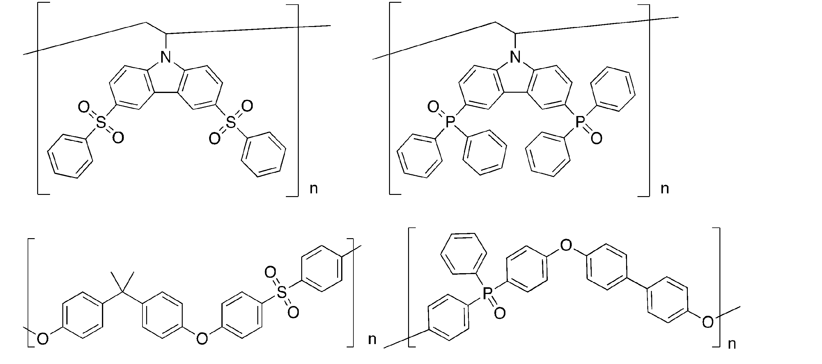
[第3有機化合物]
本発明の蓄光組成物に用いる第3有機化合物は、発光材料であることが好ましい。第3有機化合物の発光波長は、例えば可視光領域や近赤外線領域から選択することができる。具体的には、第3有機化合物の発光波長は、200~2000nmであることが好ましい。例えば、400nm以上、600nm以上、800nm以上、1000nm以上、1200nm以上の波長領域から選択してもよいし、1500nm以下、1100nm以下、900nm以下、700nm以下、500nm以下の領域から選択してもよい。また、第3有機化合物はキャリアトラップ機能を有することも好ましい。
第3有機化合物は、蛍光材料、燐光材料、遅延蛍光材料のいずれであってもよく、目的の発光色に応じて、公知のものから選択して用いることができる。ここで、「蛍光材料」とは、室温下で燐光の発光強度よりも蛍光の発光強度の方が高い発光材料であり、「燐光材料」とは、室温下で蛍光の発光強度よりも燐光の発光強度の方が高い発光材料であり、「遅延蛍光材料」とは、室温下で発光寿命が短い蛍光と、発光寿命が長い蛍光(遅延蛍光)の両方が観測される発光材料である。通常の蛍光(遅延蛍光ではない蛍光)は、発光寿命がnsオーダーであり、燐光は、通常、発光寿命がmsオーダーであるため、蛍光と燐光とは発光寿命により区別することができる。また、有機金属錯体以外の発光性の有機化合物は、通常蛍光材料または遅延蛍光材料である。
例えば、蛍光材料としては、実施例で使用しているTTPA(緑色発光材料)、TBRb(オレンジ色発光材料)、DCM2(赤色発光材料)を好ましく用いることができる。また、燐光材料としては、実施例で使用しているIr(ppy)3、Ir(piq)3、Ir(btp)2(acac)、PtOEPを好ましく用いることができる。
蓄光組成物における第3有機化合物の含有量は、第1有機化合物、第2有機化合物および第3有機化合物の合計モル数に対して50mol%未満であることが好ましく、25mol%未満であることがより好ましく、0.001~20mol%であることがさらに好ましく、0.001~10mol%であることがさらにより好ましい。蓄光組成物における第3有機化合物の濃度を変化させることにより、蓄光組成物の発光波長を制御することができる。例えば、ES1(B) ー ES1(A)が負の値になる第3有機化合物を用いた蓄光組成物では、第3有機化合物の濃度を高くすると、発光波長が長波長化する傾向があり、近赤外線領域の発光を得ることも可能である。
[その他の成分]
蓄光組成物は、第1有機化合物と第2有機化合物と第3有機化合物のみから構成されていてもよいし、その他の成分が添加されていてもよいし、蓄光組成物の成分を溶解する溶媒を含んでいてもよい。その他の成分として、キャリアトラップ材料を挙げることができる。キャリアトラップ材料を添加することにより、電荷分離により生じた第2有機化合物のラジカルカチオンからキャリアトラップ材料への電子移動がおき、キャリアトラップ材料中で電子をより安定に蓄積することができる。キャリアトラップ材料に蓄積された電子は熱などのエネルギーで再び第2有機化合物に戻って第3有機化合物に移動し、第1有機化合物のホールと再結合することで蓄光発光が得られる。
キャリアトラップ材料としては、そのLUMO準位が第2有機化合物のLUMO準位と近い材料が好ましい。キャリアトラップ材料のLUMO準位は、第2有機化合物のLUMO準位より0.001eV以上低いことが好ましく、0.01eV以上低いことがより好ましく、0.1eV以上低いことがさらに好ましい。また、キャリアトラップ材料のLUMO準位と、第2有機化合物のLUMO準位との差は、0.5eV以下であることが好ましく、0.4eV以下であることがより好ましく、0.3eV以下であることがさらに好ましい。
[発光の態様]
本発明の蓄光組成物は、光が照射されることにより、光照射を停止した後にも、発光(残光)が長時間継続する。
蓄光組成物の発光は、蓄光材料からの発光と、第3有機化合物からの発光を少なくとも含む。蓄光材料からの発光は、励起された第1有機化合物と第2有機化合物が会合(凝集)してエキサイプレックスを形成し、そのエキサイプレックスからの放射緩和による発光(エキサイプレックス発光)であることが好ましい。蓄光材料がエキサイプレックスを形成して発光する場合、蓄光材料からの発光はエキサイプレックス発光のみであってもよいし、第2有機化合物と会合していない第1有機化合物からの発光や、第1有機化合物と会合していない第2有機化合物からの発光を含んでいてもよい。発光する光は、蛍光および燐光のいずれか一方であってもよく、蛍光と燐光の両方であってもよいし、さらに、遅延蛍光を含んでいてもよい。
蓄光組成物から残光を得るための励起光は、太陽光であってもよいし、特定の波長範囲の光を出射する人工光源からの光であってもよい。
蓄光組成物から残光を得るために行う光照射の時間は、1μ秒以上であることが好ましく、1m秒以上であることがより好ましく、1秒以上であることがさらに好ましく、10秒以上であることがさらにより好ましい。これにより、ラジカルアニオンとラジカルカチオンを十分に生成することができ、光照射を停止した後に、発光を長時間継続させることができる。
蓄光組成物の発光波長は、第1有機化合物~第3有機化合物の組み合わせにより広く制御することができ、特に制限されないが、200~2500nmであることが好ましい。また、蓄光組成物の発光波長は、380~750nmの可視光領域であることも好ましく、700~2500nmの近赤外線領域であることも好ましい。近赤外線領域の光は、生体に対する透過性が高いことから、生体深部の可視化や診断に利用することができ、バイオや医療技術、光損失の少ない通信技術等、様々な分野に応用することができる。
[蓄光組成物の形態]
本発明の蓄光組成物は、第1有機化合物と第2有機化合物と第3有機化合物を含有していればよく、その形態は特に限定されない。このため、第1有機化合物と第2有機化合物と第3有機化合物を混合した混合物であってもよいし、蓄光材料を構成する第2有機化合物および第1有機化合物と、第3有機化合物がそれぞれ別の領域に存在しているものであってもよい。蓄光材料と第3有機化合物を混合した混合物としては、例えば、蓄光材料と第3有機化合物を溶媒に溶解して得た溶液や、蓄光材料と第3有機化合物を含む薄膜(蓄光膜)を挙げることができる。また、第2有機化合物、第1有機化合物および第3有機化合物がそれぞれ別の領域に存在している例としては、第2有機化合物および第3有機化合物のそれぞれに対して100質量倍以上の量の第1有機化合物を含む領域と、第1有機化合物および第3有機化合物のそれぞれに対して100質量倍以上の量の第2有機化合物を含む領域と、第1有機化合物および第2有機化合物のそれぞれに対して100重量倍以上の量の第3有機化合物を含む領域を有するもの、第2有機化合物および第3有機化合物を含まず第1有機化合物を含む領域と、第1有機化合物および第3有機化合物を含まず第2有機化合物を含む領域と、第1有機化合物および第2有機化合物を含まず第3有機化合物を含む領域を有するもの、これらの3つの領域が互いに接しているもの、これらの領域が層状(薄膜を含む)であるものを挙げることができる。
蓄光材料と第3有機化合物を用いた薄膜は、ドライプロセス、ウェットプロセスのどちらで成膜されたものであってもよい。例えば、加熱溶融させた第2有機化合物の融液に第1有機化合物および第3有機化合物を添加して混合し、冷却して得たガラス状の薄膜であってもよい。ウェットプロセスで成膜するときに用いる溶媒は、溶質となる第1有機化合物や第2有機化合物、第3有機化合物に相溶性を有する有機溶媒であればよい。有機溶媒を用いて、例えば、第2有機化合物、第1有機化合物および第3有機化合物の混合溶液を調製したり、第2有機化合物だけを溶解した溶液を調製したり、第1有機化合物のみを溶解した溶液を調製したり、第3有機化合物のみを溶解した溶液を調製することができる。混合溶液を支持体上に塗布して乾燥すれば第1有機化合物、第2有機化合物および第3有機化合物の混合薄膜を形成することができ、また、支持体上に第1有機化合物の溶液と第2有機化合物の溶液と第3有機化合物の溶液を順次塗布して乾燥することにより第1有機化合物の薄膜と第2有機化合物の薄膜と第3有機化合物の薄膜とを互いに接するように形成することもできる(第1有機化合物の溶液と第2有機化合物の溶液と第3有機化合物の溶液の塗布順は順不同である)。
薄膜の平面形状は用途に応じて適宜選択することができ、例えば、正方形状、長方形状等の多角形状、真円状、楕円状、長円状、半円状のような連続形状であってもよいし、幾何学模様や文字、図形等に対応する特定のパターンであってもよい。
[蓄光素子]
本発明の蓄光素子は、本発明の蓄光組成物を支持体上に有するものである。蓄光組成物は通常は膜状にして支持体上に形成される。支持体上に形成される膜は、単一膜でもよいし、複数の膜からなるものであってもよい。単一膜や、複数の膜のうちの一部の膜は、第1有機化合物、第2有機化合物および第3有機化合物のうちの2以上を含む膜とすることができる。また、複数の膜のうちの一部の膜を、第2有機化合物を含み第1有機化合物および第3有機化合物を含まない膜とし、一部の膜を、第1有機化合物を含み第2有機化合物および第3有機化合物を含まない膜とし、さらに一部の膜を、第3有機化合物を含み第1有機化合物および第2有機化合物を含まない膜とすることもできる。このとき、これらの3種類の膜は互いに接するように構成することもできる。
蓄光組成物については、蓄光組成物の欄の対応する記載を参照することができる。なお、蓄光組成物の形態については、蓄光組成物の形態の欄の薄膜についての記載を参照することができる。
支持体については、特に制限はなく、蓄光材料に慣用されているものであればよい。支持体の材料として、例えば紙、金属、プラスチック、ガラス、石英、シリコン等を挙げることができる。可撓性がある支持体に形成することもできるため、用途に応じて様々な形状にすることも可能である。
蓄光膜は、全体が封止材により覆われていることが好ましい。封止材には、ガラス、エポキシ樹脂等の水や酸素の透過率が低い透明材料を用いることができる。
本発明によれば、透明な組成物を提供することが可能である。このため、従来の無機材料と異なり、多様な用途に使用し、応用することが可能である。例えば、ガラス等の透明な材料でできた2枚の支持体で本発明の透明な蓄光組成物を挟み込むことにより、透明な蓄光板を形成すること等が可能である。支持体の透明性を調節すれば、半透明な蓄光板にすることもできる。また、本発明によれば、発光色が異なる透明な蓄光膜を積層することにより、外部へ放出される光の色味を調整することも可能である。
[蓄光組成物の用途]
本発明の蓄光組成物は、上記のように、発光波長制御が容易であるという特徴を有するとともに、例えば、有機化合物としての第1有機化合物、第2有機化合物および第3有機化合物を溶媒中で混合し塗布するだけで、蓄光品を構成することができる。そのため、本発明の蓄光組成物は、希少元素を含む無機材料の高温焼成、微粒子化および分散工程を用いて蓄光品を構成する無機蓄光材料に比べて、材料調達が容易であるとともに、蓄光品の製造コストが低く抑えられ、また、蓄光品に透明性・フレキシブル性・柔軟性を持たせることができるというメリットがある。よって、本発明の蓄光組成物は、一般的な蓄光品に用いうることの他、上記の特徴を活かして、これまでにない新規な用途を実現することができる。
例えば、本発明の蓄光組成物は、第1有機化合物および第2有機化合物と組み合わせる第3有機化合物の選択により、青色光~近赤外線領域に亘る広い波長範囲で発光波長を制御することができる。このうち、緑色光を発光する蓄光組成物は、緑色の視感強度が強いため、標識用の蓄光塗料として効果的に用いることができる。また、赤色~近赤外領域の光を発光する蓄光組成物は、その波長領域の光が生体を透過しやすいため、バイオイメージングに用いる標識材料として有用である。さらに、様々な発光色の蓄光組成物を組み合わせて使用することにより、意匠性に優れた物品を提供することができ、また、パスポートなどの公文書偽造防止システムなどにも応用することができる。
また、本発明の蓄光組成物を溶媒に溶解することにより、塗布性に優れた蓄光塗料を構成することができる。こうした蓄光塗料を道路や建築物内装面に全面的に塗布することにより、電源が不要な大規模蓄光照明を実現することができる。また、この蓄光塗料で車道外側線を引いた場合には、暗闇でも車道外側線が認知できるようになり、車両通行の安全性を格段に向上させることができる。
さらに、この蓄光塗料で描いた安全誘導標識を用いれば、災害時に長時間にわたる安全な避難誘導が実現するほか、この蓄光塗料を省エネ照明、住宅建材、鉄道、モバイル機器などにコーティングして災害時避難システムの構築が可能となる。
また、本発明の蓄光組成物を含有する蓄光塗料は印刷用インキとしても用いることもできる。これにより、意匠性に優れ、暗闇や災害時の誘導にも用いうる印刷物を得ることができる。こうした蓄光印刷用インキは、例えば、表紙、パッケージ、ポスター、POP、ステッカー、案内看板、避難誘導サイン、安全用品、防犯用品のための印刷に好ましく用いることができる。
また、第1有機化合物、第2有機化合物および第3有機化合物の少なくともいずれかがポリマーである蓄光組成物(蓄光ポリマー)や、本発明の蓄光組成物に市販の半導体性ポリマーを添加した組成物を用いることにより、蓄光成形品を得ることができる。
こうした蓄光成形品として、例えば電飾看板、商品ディスプレイ、液晶バックライト、照明ディスプレイ、照明器具カバー、交通標識、安全標識、夜間視認性向上部材、サインボード、スクリーン、反射板やメーター部品等の自動車部品、娯楽施設の遊具や玩具、ノートパソコン、携帯電話などのモバイル機器をはじめ、自動車室内や建物内の標示ボタン、時計の文字盤、アクセサリー類、文具類、スポーツ用品、各種の電気・電子・OA機器等の分野における筐体やスイッチ、ボタン類等を挙げることができる。
また、本発明の蓄光組成物は透明性に優れるため、この蓄光組成物をガラスの表面にコーティングするか、蓄光組成物と樹脂の混合物を薄板状に成形することで、蓄光機能を有する調光窓を実現することができる。さらに、蓄光組成物からなる薄板と反射板を積層した場合には、高輝度の蓄光板を得ることができる。こうした蓄光板は、発光誘導タイルとして、各種災害に伴う避難経路道部材、階段段板、蹴込版、框材、溝蓋材、屋外駐車場部材、港湾整備部材、道路施設安全部材、高所作業足場部材、海上浮遊施設足場部材、山岳遊歩道関連部材、耐塩害性耐候看板等に用いることができる。
また、本発明の蓄光組成物を繊維にコーティングすることにより、蓄光繊維やそれを用いた布類や蓄光衣類を得ることができる。こうした蓄光繊維品として、夜間用作業衣、帽子、非常通路用カーペット、ブライダル衣装、壁掛け、車両用内装材等を挙げることができる。
この他にも、本発明の蓄光組成物は、蓄光フィルム、蓄光テープ、蓄光シール、蓄光建材、蓄光スプレーなど、様々な素材を構成することができる。いずれにおいても、発光波長制御が容易なことと、各成分を有機化合物で構成できることにより、色の選択の幅が広く、透明で柔軟な性状を各素材に付与することができ、意匠性や標識性、取り扱い性に優れたものとすることができる。例えば、蓄光フィルムは、避難誘導や防災グッズの包装材として幅広く利用することができる。
さらに、本発明の蓄光組成物は、蓄光材料の電荷分離状態が比較的長寿命の傾向がある。そのため、広い分野で様々な用途に用いることができる。例えば、本発明の蓄光組成物は、光エネルギーにより電荷分離状態を形成して物質の生産に導く人工光合成の分野に応用することができる。また、本発明の蓄光組成物は、熱エネルギーや力学的エネルギーに応答する素子としても効果的に用いることができる。例えば、熱エネルギーに応答する素子として、励起光の照射により蓄光材料を電荷分離状態とした後、蓄光組成物に熱を加えて瞬発的に発光させる熱スイッチングを挙げることができる。また、力学的エネルギーに応答する素子として、蓄光材料を電荷分離状態とした蓄光組成物に、圧力などの力学的エネルギーを加えることによって発光する素子や、蓄光材料を電荷分離状態とした蓄光組成物に、圧力などの力学的エネルギーを加えることによって発光状態が変化する素子を挙げることができる。また、それらの応用例として、熱など外的刺激に応答するインタラクティブ発光アートを挙げることができる。
以下に実施例を挙げて本発明の特徴をさらに具体的に説明する。以下に示す材料、処理内容、処理手順等は、本発明の趣旨を逸脱しない限り適宜変更することができる。したがって、本発明の範囲は以下に示す具体例により限定的に解釈されるべきものではない。なお、励起光には、340nmのLEDライト(Thorlabs社製:M340L4)を使用した。また、発光スペクトル、残光スペクトルおよび発光寿命、フォトルミネッセンス量子収率の測定は、分光測定装置(HORIBA Jobin Yvon社製:FLUOROMAX、浜松ホトニクス社製:PMA-12)、マルチチャンネルスペクトロメーター(オーシャンオプティクス社製:QE-Pro)、マルチメーター(キーサイト社製:34461A)、PL量子収率測定装置(浜松ホトニクス社製:Quantaurus-QY)を用いて行った。
実施例や比較例で用いた化合物の最低励起一重項エネルギー準位(ES1)と最低励起三重項エネルギー準位(ET1)は以下の手順により求めた。
(1)最低励起一重項エネルギー準位(ES1)
測定対象化合物を含む10-5mol/L濃度のトルエン溶液またはクロロホルム溶液を調製した。常温(300K)でこの試料に励起光を照射し、蛍光スペクトルを測定し、励起光入射直後から入射後100ナノ秒までの発光を積算することで、縦軸を発光強度、横軸を波長の蛍光スペクトルを得た。蛍光スペクトルは、縦軸を発光、横軸を波長とした。この発光スペクトルの短波長側の立ち上がりに対して接線を引き、その接線と横軸との交点の波長値 λedge[nm]を求めた。この波長値を次に示す換算式でエネルギー値に換算した値をES1とした。
換算式:ES1[eV]=1239.85/λedge
(2)最低励起三重項エネルギー準位(ET1)
最低励起一重項エネルギー準位(ES1)と同じ試料を77[K]に冷却し、励起光(340nm)を燐光測定用試料に照射し、PMA―12を用いて、燐光強度を測定した。励起光入射後1ミリ秒から入射後10ミリ秒の発光を積算することで、縦軸を発光強度、横軸を波長の燐光スペクトルを得た。この燐光スペクトルの短波長側の立ち上がりに対して接線を引き、その接線と横軸との交点の波長値λedge[nm]を求めた。この波長値を次に示す換算式でエネルギー値に換算した値をET1とした。
換算式:ET1[eV]=1239.85/λedge
燐光スペクトルの短波長側の立ち上がりに対する接線は以下のように引いた。燐光スペクトルの短波長側から、スペクトルの極大値のうち、最も短波長側の極大値までスペクトル曲線上を移動する際に、長波長側に向けて曲線上の各点における接線を考えた。この接線は、曲線が立ち上がるにつれ(つまり縦軸が増加するにつれ)、傾きが増加した。この傾きの値が極大値をとる点において引いた接線を、当該燐光スペクトルの短波長側の立ち上がりに対する接線とした。
[実施例および比較例で使用した化合物]
実施例および比較例では、第1有機化合物としてTMBを用い、第2有機化合物としてPPT、m-MTDATA、CV、を用い、第3有機化合物として4CzBN、2CzPN、Flrpic、TBPe、4CzIPN、5CzPN、TTPA、TBRb、DCM2、NileRed、DBP、Ir(ppy)3、Ir(piq)3、Ir(btp)2(acac)、PtOEPを使用した。これらの化合物の構造は以下の通りである。
実施例および比較例では、第1有機化合物としてTMBを用い、第2有機化合物としてPPT、m-MTDATA、CV、を用い、第3有機化合物として4CzBN、2CzPN、Flrpic、TBPe、4CzIPN、5CzPN、TTPA、TBRb、DCM2、NileRed、DBP、Ir(ppy)3、Ir(piq)3、Ir(btp)2(acac)、PtOEPを使用した。これらの化合物の構造は以下の通りである。

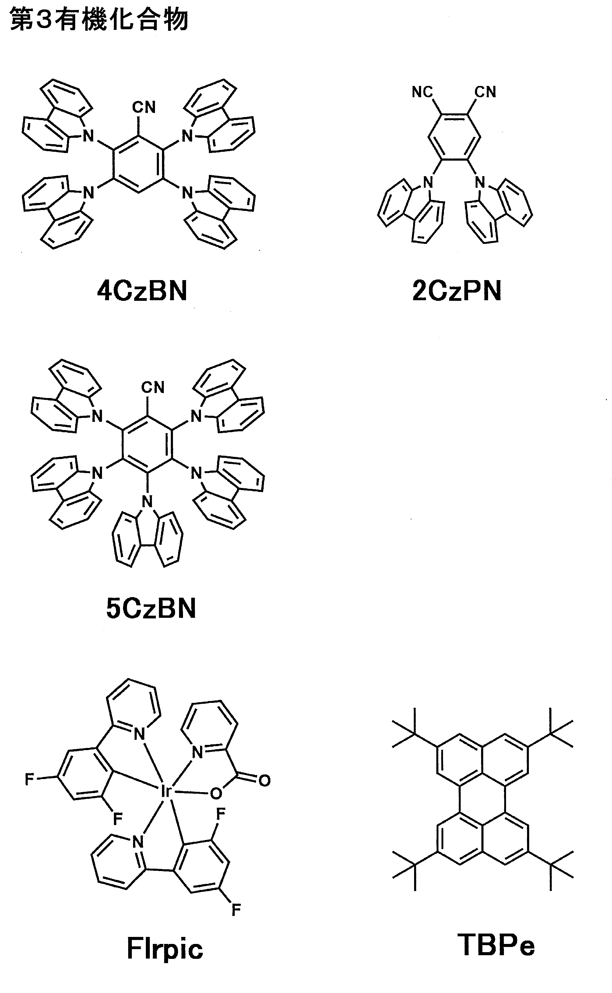
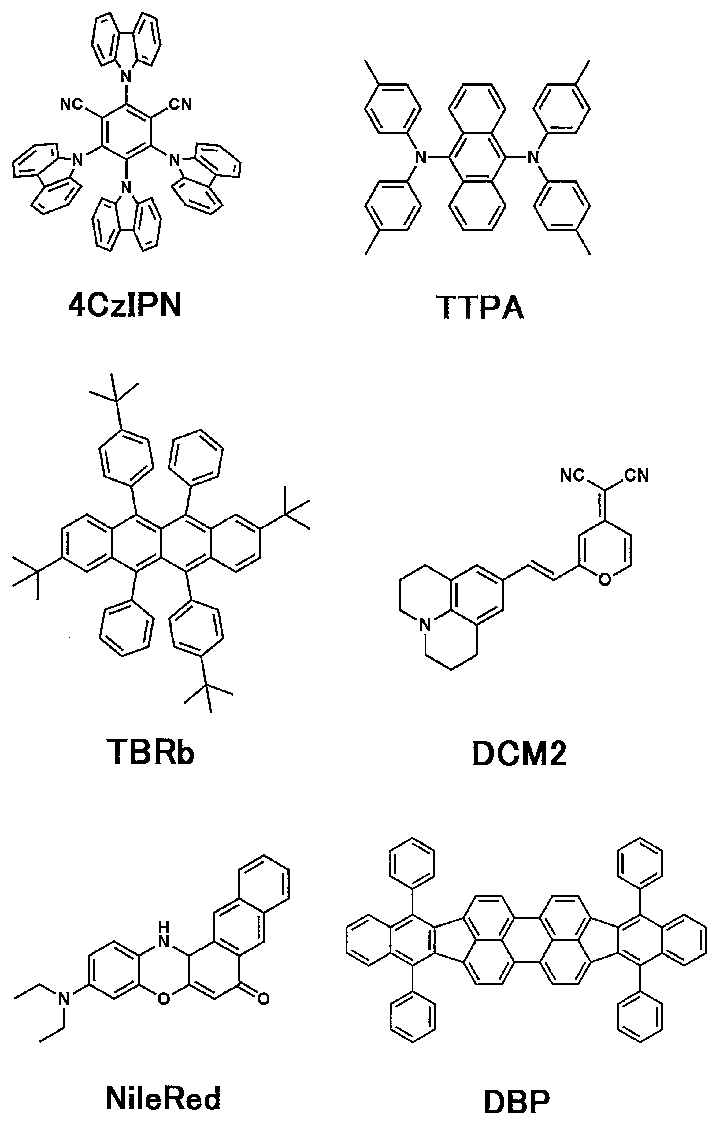
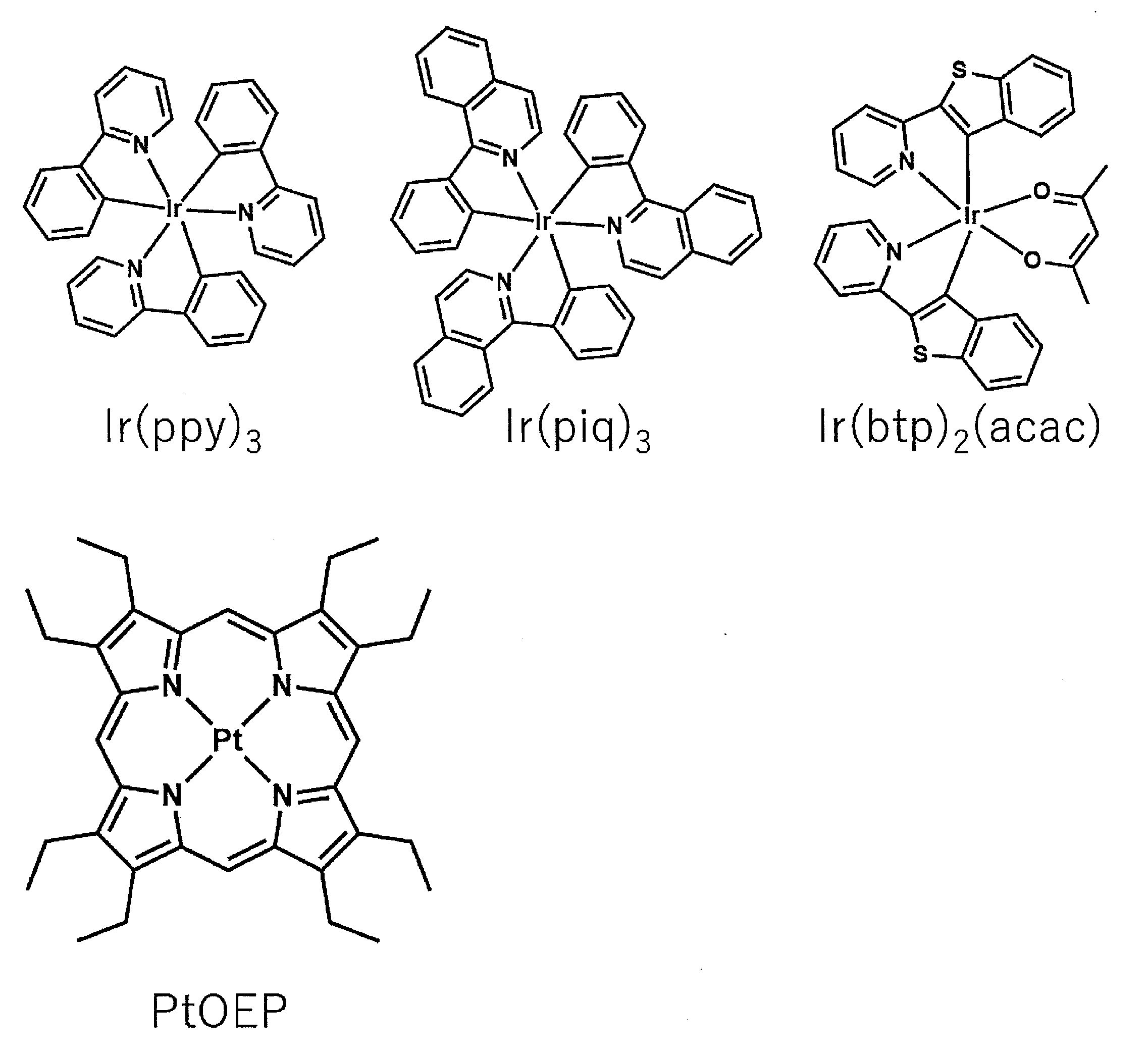
[1]第1有機化合物と第2有機化合物の組み合わせの検討
窒素雰囲気のグローブボックス中で、石英基板をPPTの融点以上(250℃以上)の温度に加熱し、その石英基板の上でPPTを融解させた。このPPTの融液に、TMBを1mol%の濃度で添加して混合し、急冷することでガラス状態の蓄光材料膜を形成し、ガラス基板と紫外線硬化樹脂で封止した。形成した膜に340nmの励起光を照射したところ発光が認められ、照射をやめた後も残光が認められた。図2に残光スペクトルおよび発光寿命特性を示す。残光スペクトルのピーク波長は526nmであった。
TMBのかわりに、m-MTDATAまたはCVを用いた点を変更して、同様にしてガラス状態の膜を形成した。m-MTDATAおよびCVを用いた膜は、照射をやめた後も残光が認められた。m-MTDATAを用いた膜について、残光スペクトルと発光寿命特性を調べた結果を図3に示し、CVを用いた膜について、残光スペクトルと発光寿命特性を調べた結果を図4に示す。m-MTDATAを用いた膜の残光スペクトルのピーク波長は523nmであり、CVを用いた膜の残光スペクトルのピーク波長は513nmであった。
[2]溶液および膜状の蓄光組成物の調製と特性の評価
(実施例1~7、比較例1~4)
PPT99mol%に対してTMBを1mol%となる量で混合し、PPTの融点以上(250℃以上)の温度で加熱融解した後、急冷し蓄光材料膜を得た。この膜からの発光の最低励起一重項エネルギー準位を測定し、ES1(A)とした。
また、4CzBN、2CzPN、5CzPN、Flrpic、TBPe、4CzIPN、TTPA、TBRb、DCM2、NileRed、DBPのそれぞれについて、10-5mol/L濃度のトルエン溶液を調製し、最低励起一重項エネルギー準位を測定することにより各化合物のES1(B)を決定した。結果を表1に示す。
PPT98mol%に対してTMBを1mol%となる量で混合し、第3化合物である4CzBNを1mol%となる量で混合し、加熱融解した後、急冷し蓄光膜を得た。さらに、4CzBNのかわりに、2CzPN、5CzPN、Flrpic、TBPe、4CzIPN、TTPA、TBRb、DCM2、NileRed、DBPを第3化合物として用いて同様にして蓄光膜を得た。
調製した各蓄光膜について、340nm励起光を照射したところ発光が認められ、照射をやめた後もすべての蓄光膜から残光が認められた。蓄光膜の残光スペクトルおよび発光寿命特性を調べ、ピーク波長と半値幅(FWHM)を決定した。結果を表1に示す。代表的な発光寿命特性として、TTPA、TBRb、DCM2を含む蓄光膜の発光寿命特性を図5に示す。図中「OLPL」はTMB/PPTの組み合わせを示す。また、代表的な残光スペクトルとして、TTPA、TBRb、DCM2、TBPeを含む蓄光膜の残光スペクトルを図6に示す。これらの残光スペクトルは、TMB/PPTの残光スペクトルとは明らかに異なっており、ピーク波長もシフトして発光波長制御ができていた。特に、式(1)のES1(B)-ES1(A)が負であるTTPA、TBRb、DCM2を含む蓄光膜では長波長側への制御が達成され、ES1(B)-ES1(A)が0超0.15eV以下の正の値をとるTBPeを含む蓄光膜では短波長側への制御が達成された。一方、式(1)の関係を満たさない4CzBN、2CzPN、5CzPN、Flrpicを含む蓄光膜については、残光スペクトルのピーク波長がTMB/PPT溶液と同じで、TMB/PPTからこれらの第3有機化合物へのエネルギー移動がなされていないことが確認された。
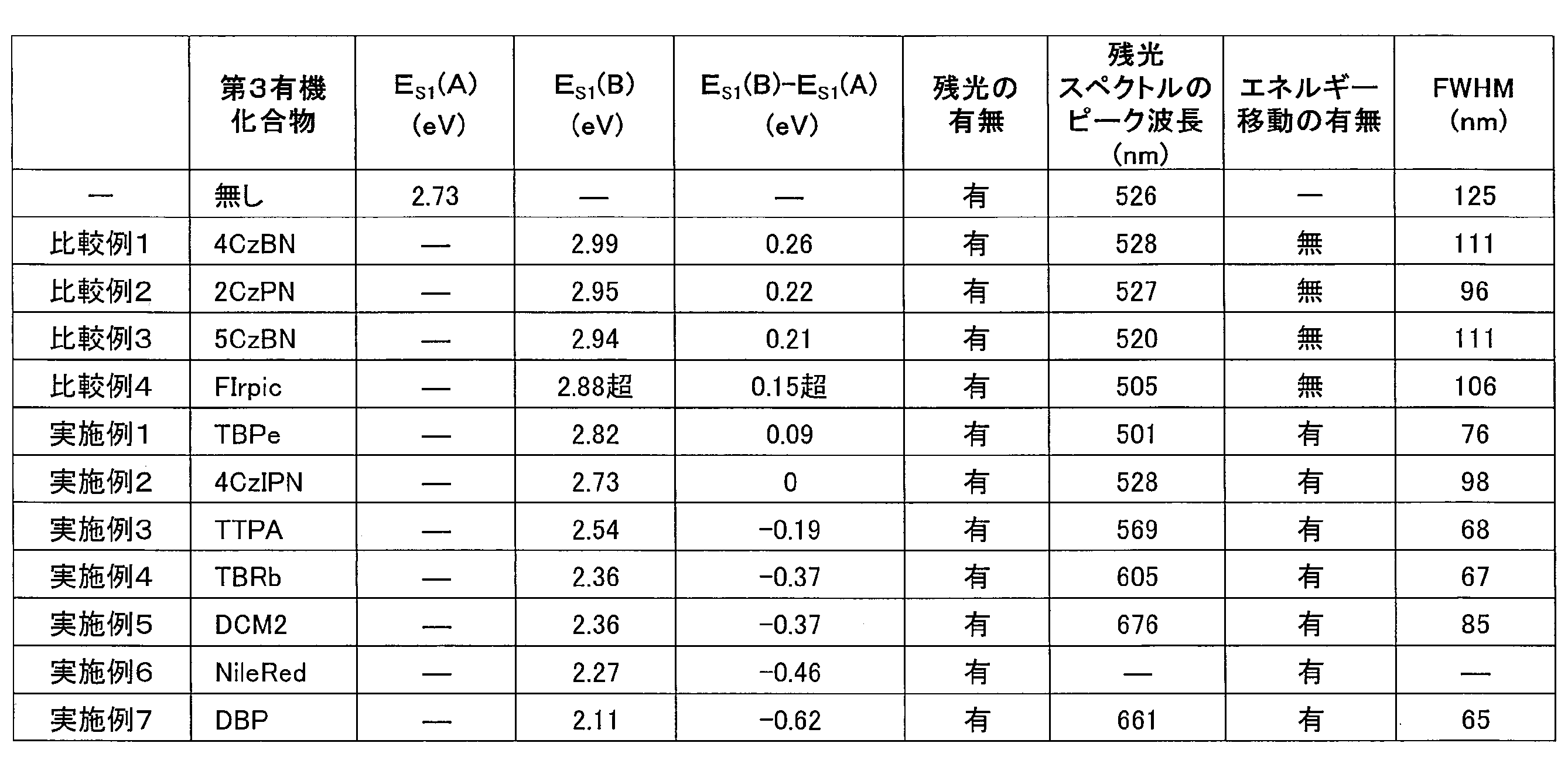
また、実施例1、3、4、5で作製した蓄光膜と、第3有機化合物無しの蓄光膜について、340nm励起光によるフォトルミネッセンス量子収率(PL量子収率)と残光時間を測定した。結果を表2に示す。ここで残光時間は、励起光の照射をやめた時点から発光強度が3pW未満になるまでの時間である。

表2から示されるように、蓄光膜に第3有機化合物を添加した各実施例の蓄光膜は、いずれも第3有機化合物無しの蓄光膜よりもフォトルミネッセンス量子収率が高く、また、残光が長時間持続した。特に、第3有機化合物としてTBRbを添加した実施例4の蓄光膜では、第3有機化合物無しの蓄光膜に比べて3.5倍のフォトルミネッセンス量子収率と6倍に近い残光時間が達成された。このことから、蓄光膜に第3有機化合物を添加することにより、発光効率と残光時間が劇的に改善されることがわかった。
(実施例8)
PPT83mol%に対してTMBを1mol%となる量で混合し、第3化合物であるDCM2を16mol%となる量で混合し、加熱融解した後、急冷し蓄光膜を得た。
この蓄光膜について、340nm励起光を照射したところ、ピーク波長が711nmの発光が認められ、照射をやめた後も蓄光膜から残光が認められた。また、その発光ピークの半値幅(FWHM)は134nmであった。このことから、DCM2を蓄光膜に高濃度で添加することにより、発光波長が長波長化し、近赤外発光を実現できることがわかった。
PPT83mol%に対してTMBを1mol%となる量で混合し、第3化合物であるDCM2を16mol%となる量で混合し、加熱融解した後、急冷し蓄光膜を得た。
この蓄光膜について、340nm励起光を照射したところ、ピーク波長が711nmの発光が認められ、照射をやめた後も蓄光膜から残光が認められた。また、その発光ピークの半値幅(FWHM)は134nmであった。このことから、DCM2を蓄光膜に高濃度で添加することにより、発光波長が長波長化し、近赤外発光を実現できることがわかった。
(比較例5)PPTとTTPAの膜の作製
窒素雰囲気のグローブボックス中で、石英基板をPPTの融点以上(250℃以上)の温度に加熱し、その石英基板の上でPPTを融解させた。このPPTの融液にTTPAを1重量%の濃度で添加して混合し、急冷することでガラス状態の蓄光材料膜を形成し、ガラス基板と紫外線硬化樹脂で封止した。
窒素雰囲気のグローブボックス中で、石英基板をPPTの融点以上(250℃以上)の温度に加熱し、その石英基板の上でPPTを融解させた。このPPTの融液にTTPAを1重量%の濃度で添加して混合し、急冷することでガラス状態の蓄光材料膜を形成し、ガラス基板と紫外線硬化樹脂で封止した。
(比較例6)PPTとDCM2の膜の作製
TTPAの代わりにDCM2を用いること以外は、比較例1と同様にして膜を作製した。
TTPAの代わりにDCM2を用いること以外は、比較例1と同様にして膜を作製した。
TMBとPPTからなる蓄光材料膜、実施例3で作製したTMB/PPT/TTPAからなる蓄光膜およびTTPAのトルエン溶液(10-5mol/L)の340nm励起光による発光スペクトルと、TTPAのトルエン溶液の光吸収スペクトルを図7に示し、この蓄光膜、蓄光材料膜、および比較例5で作製したPPTとTTPAの膜の発光寿命を調べた結果を図8に示す。
TMBとPPTからなる蓄光材料膜、実施例4で作製したTMB/PPT/TBRbからなる蓄光膜およびTBRbのトルエン溶液(10-5mol/L)の340nm励起光による発光スペクトルと、TBRbのトルエン溶液の光吸収スペクトルを図9に示し、この蓄光膜および蓄光材料膜の発光寿命を調べた結果を図10に示す。
TMBとPPTからなる蓄光材料膜、実施例5で作製したTMB/PPT/DCM2からなる蓄光膜およびDCM2のトルエン溶液(10-5mol/L)の340nm励起光による発光スペクトルと、DCM2のトルエン溶液の光吸収スペクトルを図11に示し、この蓄光膜、蓄光材料膜、および比較例6で作製したPPTとDCM2の膜の発光寿命を調べた結果を図12に示す。
図7、9、11中、点線は光吸収スペクトルを表し、その他の波形は発光スペクトルを表す。
図7、9、11を見ると、蓄光材料と第3有機化合物を含有する蓄光膜の発光ピークは、蓄光材料膜や第3有機化合物のトルエン溶液の発光ピークよりも長波長側にシフトしてことがわかる。このことから、蓄光材料と第3有機化合物を組み合わせて用いることにより、蓄光材料または第3有機化合物のみでは得られない、より波長が長い発光色が得られ、広い波長範囲での発光色制御が可能になることがわかった。特に、無機蓄光材料では実現することが困難であった赤色発光を高い色純度で観測できたことは極めて画期的である(図11参照)。
また、図8、10、12から、各実施例で作製した蓄光膜は、蓄光材料膜よりも長寿命で発光強度も向上していることがわかった。
(実施例9)白色発光膜の作製
TMBを1当量に対して、PPTを99当量、TBPeを1当量、DBPを0.01当量となる量で混合し、加熱融解した後、急冷し蓄光膜を得た。作製した蓄光膜に340nm励起光を照射したところ、CIE座標(x=0.37, y=0.42)の白色発光が認められた。図13に発光スペクトルを示し、図14に発光寿命を調べた結果を示す。
実施例9では、第3化合物として緑青色発光体であるTBPeと赤色発光体であるDBPを併用することにより、白色発光を実現することができた。
TMBを1当量に対して、PPTを99当量、TBPeを1当量、DBPを0.01当量となる量で混合し、加熱融解した後、急冷し蓄光膜を得た。作製した蓄光膜に340nm励起光を照射したところ、CIE座標(x=0.37, y=0.42)の白色発光が認められた。図13に発光スペクトルを示し、図14に発光寿命を調べた結果を示す。
実施例9では、第3化合物として緑青色発光体であるTBPeと赤色発光体であるDBPを併用することにより、白色発光を実現することができた。
(実施例10~13)
実施例10~13では、第3有機化合物として燐光材料を使用した。燐光材料については、最低励起一重項エネルギー準位ES1(B)を測定することができないため、最低励起三重項エネルギー準位ET1(B)をES1(B)の指標とした。通常の燐光材料では、最低励起一重項エネルギー準位と最低励起三重項エネルギー準位が極端に離れていることはないため、ET1(B)-ES1(A)が-0.1eV未満、好ましくは-0.3eV未満であれば、ES1(B)- ES1(A) ≦ 0.15eVであるとみなすことができる。
具体的には、まず、Ir(ppy)3、Ir(piq)3、Ir(btp)2(acac)、PtOEPのそれぞれについて、10-5mol/L濃度のクロロホルム溶液を調製し、励起光380nmを照射し、最低励起三重項エネルギー準位ET1(B)を測定した。結果を表3に示す。
PPT98mol%に対してTMBを1mol%となる量で混合し、第3化合物であるIr(ppy)3を1mol%となる量で混合し、加熱融解した後、急冷し蓄光膜を得た。さらに、Ir(ppy)3のかわりに、Ir(piq)3、Ir(btp)2(acac)、PtOEPを第3化合物として用いて同様にして蓄光膜を得た。
調製した各蓄光膜について、340nm励起光を照射したところ発光が認められ、照射をやめた後もすべての蓄光膜から残光が認められた。蓄光膜の残光スペクトルを調べ、ピーク波長と半値幅(FWHM)を決定した。結果を表3に示す。表3に示したように、これらのピーク波長は、TMB/PPT(表3中の第3有機化合物「無し」の例)のピーク波長から長波長側へシフトしており、発光波長制御ができていることを確認することができた。

本発明の蓄光組成物は、発光色制御が容易であり、従来の無機蓄光材料では実現することが困難であった赤色光も高い色純度で発光することができ、また白色光を実現することもできる。このため、本発明によれば、多様な色合を有する蓄光材を実現することが可能である。よって、本発明の蓄光組成物は、産業上の利用可能性が高い。
Claims (15)
- 第1有機化合物と第2有機化合物と第3有機化合物とを少なくとも含み、下記式(1)を満たす有機蓄光組成物。
式(1) ES1(B)- ES1(A) ≦ 0.15eV
(上式において、ES1(A)は前記第1有機化合物と前記第2有機化合物からなる発光の最低励起一重項エネルギー準位を表し、ES1(B)は前記第3有機化合物の最低励起一重項エネルギー準位を表す。ES1(A)とES1(B)の単位はeVである。) - 下記式(2)を満たす、請求項1に記載の蓄光組成物。
式(2)
0eV < ES1(B)- ES1(A) ≦ 0.15eV - 下記式(3)を満たす、請求項1に記載の蓄光組成物。
式(3) ES1(B)- ES1(A) < 0eV - 前記第1有機化合物と前記第2有機化合物からなる組成物が蓄光材料である、請求項1~3のいずれか1項に記載の蓄光組成物。
- 前記蓄光組成物への光照射により、前記第1有機化合物と前記第2有機化合物がエキサイプレックスを形成する、請求項1~4のいずれか1項に記載の蓄光組成物。
- 前記第1有機化合物が電子ドナー性化合物であり、前記第2有機化合物が電子アクセプター性化合物である、請求項1~5のいずれか1項に記載の蓄光組成物。
- 前記第3有機化合物が凝集体を形成している、請求項1~6のいずれか1項に記載の蓄光組成物。
- 前記凝集体がエキシマーである、請求項7に記載の蓄光組成物。
- 前記第3有機化合物が蛍光材料である、請求項1~8のいずれか1項に記載の蓄光組成物。
- 請求項1~9のいずれか1項に記載の蓄光組成物を支持体上に有する蓄光素子。
- 第1有機化合物と第2有機化合物を含む蓄光材料の発光波長を制御する方法であって、
前記蓄光材料に、下記式(1)を満たす第3有機化合物を添加することを特徴とする波長制御方法。
式(1) ES1(B)- ES1(A) ≦ 0.15eV
(上式において、ES1(A)は前記第1有機化合物と前記第2有機化合物からなる発光の最低励起一重項エネルギー準位を表し、ES1(B)は前記第3有機化合物の最低励起一重項エネルギー準位を表す。ES1(A)とES1(B)の単位はeVである。) - 前記第3有機化合物が下記式(2)を満たす、請求項11に記載の波長制御方法。
式(2)
0eV < ES1(B)- ES1(A) ≦ 0.15eV - 前記第3化合物を添加することにより、蓄光材料の発光波長を短波長側に制御する、請求項12に記載の波長制御方法。
- 前記第3有機化合物が下記式(3)を満たす、請求項11に記載の波長制御方法。
式(3) ES1(B)- ES1(A) < 0eV - 前記第3化合物を添加することにより、蓄光材料の発光波長を長波長側に制御する、請求項14に記載の波長制御方法。
Priority Applications (4)
| Application Number | Priority Date | Filing Date | Title |
|---|---|---|---|
| CN201880051565.9A CN111836871A (zh) | 2017-08-09 | 2018-08-07 | 长余辉组合物、长余辉元件及波长控制方法 |
| JP2019535685A JP7125146B2 (ja) | 2017-08-09 | 2018-08-07 | 蓄光組成物、蓄光素子および波長制御方法 |
| EP18843384.1A EP3666851A4 (en) | 2017-08-09 | 2018-08-07 | LIGHT ACCUMULATING COMPOSITION, LIGHT ACCUMULATING ELEMENT AND WAVELENGTH REGULATION METHOD |
| US16/637,879 US11505739B2 (en) | 2017-08-09 | 2018-08-07 | Long-persistent luminescent composition, long-persistent luminescent device and wavelength control method |
Applications Claiming Priority (6)
| Application Number | Priority Date | Filing Date | Title |
|---|---|---|---|
| JP2017154500 | 2017-08-09 | ||
| JP2017-154500 | 2017-08-09 | ||
| JP2017192677 | 2017-10-02 | ||
| JP2017-192677 | 2017-10-02 | ||
| JP2017-236420 | 2017-12-08 | ||
| JP2017236420 | 2017-12-08 |
Publications (1)
| Publication Number | Publication Date |
|---|---|
| WO2019031524A1 true WO2019031524A1 (ja) | 2019-02-14 |
Family
ID=65271091
Family Applications (1)
| Application Number | Title | Priority Date | Filing Date |
|---|---|---|---|
| PCT/JP2018/029660 WO2019031524A1 (ja) | 2017-08-09 | 2018-08-07 | 蓄光組成物、蓄光素子および波長制御方法 |
Country Status (6)
| Country | Link |
|---|---|
| US (1) | US11505739B2 (ja) |
| EP (1) | EP3666851A4 (ja) |
| JP (1) | JP7125146B2 (ja) |
| CN (1) | CN111836871A (ja) |
| TW (1) | TW201920055A (ja) |
| WO (1) | WO2019031524A1 (ja) |
Cited By (1)
| Publication number | Priority date | Publication date | Assignee | Title |
|---|---|---|---|---|
| US11482681B2 (en) | 2018-07-27 | 2022-10-25 | Idemitsu Kosan Co., Ltd. | Compound, material for organic electroluminescence element, organic electroluminescence element, and electronic device |
Families Citing this family (1)
| Publication number | Priority date | Publication date | Assignee | Title |
|---|---|---|---|---|
| CN117004385B (zh) * | 2023-09-28 | 2024-03-15 | 南京邮电大学 | 圆偏振发光激基复合物有机长余辉材料及制备方法和应用 |
Citations (7)
| Publication number | Priority date | Publication date | Assignee | Title |
|---|---|---|---|---|
| JP2006206618A (ja) | 2005-01-25 | 2006-08-10 | Tohoku Univ | 蓄光体の製造方法及び蓄光体 |
| JP2010245061A (ja) * | 2007-07-07 | 2010-10-28 | Idemitsu Kosan Co Ltd | 有機el素子 |
| JP2012212879A (ja) * | 2011-03-23 | 2012-11-01 | Semiconductor Energy Lab Co Ltd | 発光素子 |
| JP2015144224A (ja) * | 2013-12-26 | 2015-08-06 | 出光興産株式会社 | 有機エレクトロルミネッセンス素子および電子機器 |
| JP2015179809A (ja) * | 2013-08-14 | 2015-10-08 | 国立大学法人九州大学 | 有機エレクトロルミネッセンス素子 |
| WO2017122492A1 (ja) * | 2016-01-14 | 2017-07-20 | 国立大学法人九州大学 | 有機エレクトロルミネッセンス素子、素子群、有機エレクトロルミネッセンス素子の製造方法、有機エレクトロルミネッセンス素子の発光波長制御方法 |
| JP2018088521A (ja) * | 2016-11-17 | 2018-06-07 | 株式会社半導体エネルギー研究所 | 発光素子、表示装置、電子機器、及び照明装置 |
Family Cites Families (5)
| Publication number | Priority date | Publication date | Assignee | Title |
|---|---|---|---|---|
| US6375864B1 (en) * | 1998-11-10 | 2002-04-23 | M.A. Hannacolor, A Division Of M.A. Hanna Company | Daylight/nightglow colored phosphorescent plastic compositions and articles |
| US6863997B2 (en) * | 2001-12-28 | 2005-03-08 | The Trustees Of Princeton University | White light emitting OLEDs from combined monomer and aggregate emission |
| US7547894B2 (en) * | 2006-09-15 | 2009-06-16 | Performance Indicator, L.L.C. | Phosphorescent compositions and methods for identification using the same |
| CN105580153B (zh) * | 2013-09-17 | 2018-01-02 | 九州有机光材股份有限公司 | 有机电致发光元件 |
| EP3553151A4 (en) * | 2016-12-06 | 2019-12-11 | Kyushu University, National University Corporation | PHOSPHORESCENT SUBSTANCE AND PHOSPHORESCENT ELEMENT |
-
2018
- 2018-08-07 WO PCT/JP2018/029660 patent/WO2019031524A1/ja unknown
- 2018-08-07 JP JP2019535685A patent/JP7125146B2/ja active Active
- 2018-08-07 EP EP18843384.1A patent/EP3666851A4/en not_active Withdrawn
- 2018-08-07 CN CN201880051565.9A patent/CN111836871A/zh active Pending
- 2018-08-07 US US16/637,879 patent/US11505739B2/en active Active
- 2018-08-09 TW TW107127757A patent/TW201920055A/zh unknown
Patent Citations (7)
| Publication number | Priority date | Publication date | Assignee | Title |
|---|---|---|---|---|
| JP2006206618A (ja) | 2005-01-25 | 2006-08-10 | Tohoku Univ | 蓄光体の製造方法及び蓄光体 |
| JP2010245061A (ja) * | 2007-07-07 | 2010-10-28 | Idemitsu Kosan Co Ltd | 有機el素子 |
| JP2012212879A (ja) * | 2011-03-23 | 2012-11-01 | Semiconductor Energy Lab Co Ltd | 発光素子 |
| JP2015179809A (ja) * | 2013-08-14 | 2015-10-08 | 国立大学法人九州大学 | 有機エレクトロルミネッセンス素子 |
| JP2015144224A (ja) * | 2013-12-26 | 2015-08-06 | 出光興産株式会社 | 有機エレクトロルミネッセンス素子および電子機器 |
| WO2017122492A1 (ja) * | 2016-01-14 | 2017-07-20 | 国立大学法人九州大学 | 有機エレクトロルミネッセンス素子、素子群、有機エレクトロルミネッセンス素子の製造方法、有機エレクトロルミネッセンス素子の発光波長制御方法 |
| JP2018088521A (ja) * | 2016-11-17 | 2018-06-07 | 株式会社半導体エネルギー研究所 | 発光素子、表示装置、電子機器、及び照明装置 |
Non-Patent Citations (4)
| Title |
|---|
| HANSCH, C., CHEM. REV., vol. 91, 1991, pages 165 - 195 |
| See also references of EP3666851A4 |
| SHIN, H. ET AL.: "Blue Phosphorescent Organic Light-Emitting Diodes Using an Exciplex Forming Co-host with the External Quantum Efficiency of Theoretical Limit", ADVANCES MATERIALS, vol. 26, no. 27, 2014, pages 4730 - 4734, XP001590047, DOI: doi:10.1002/adma.201400955 * |
| ZHOU, D. ET AL.: "Host to Guest Energy Transfer Mechanism in Phosphorescent and Fluorescent Organic Light-Emitting Devices Utilizing Exciplex-Forming Hosts", THE JOURNAL OF PHYSICAL CHEMISTRY C, vol. 118, no. 41, 2014, pages 24006 - 24012, XP055531798, DOI: doi:10.1021/jp508228z * |
Cited By (1)
| Publication number | Priority date | Publication date | Assignee | Title |
|---|---|---|---|---|
| US11482681B2 (en) | 2018-07-27 | 2022-10-25 | Idemitsu Kosan Co., Ltd. | Compound, material for organic electroluminescence element, organic electroluminescence element, and electronic device |
Also Published As
| Publication number | Publication date |
|---|---|
| US11505739B2 (en) | 2022-11-22 |
| EP3666851A4 (en) | 2021-01-13 |
| JP7125146B2 (ja) | 2022-08-24 |
| CN111836871A (zh) | 2020-10-27 |
| TW201920055A (zh) | 2019-06-01 |
| JPWO2019031524A1 (ja) | 2020-09-24 |
| US20200165516A1 (en) | 2020-05-28 |
| EP3666851A1 (en) | 2020-06-17 |
Similar Documents
| Publication | Publication Date | Title |
|---|---|---|
| KR102268487B1 (ko) | 축광체 및 축광 소자 | |
| Nidhankar et al. | Efficient metal-free organic room temperature phosphors | |
| Bera et al. | Solid-state emissive organic chromophores: design, strategy and building blocks | |
| Anand et al. | Recent advances in the development of pure organic white light emitters | |
| Yokoyama et al. | Trifluoromethane modification of thermally activated delayed fluorescence molecules for high-efficiency blue organic light-emitting diodes | |
| Kubo et al. | White-light emissive materials based on dynamic polymerization in supramolecular chemistry | |
| JP6323970B1 (ja) | 蓄光体および蓄光素子 | |
| WO2015002295A1 (ja) | シート集積型希土類錯体及びその用途 | |
| Wang et al. | Purely Organic Fluorescence Afterglow: Visible‐Light‐Excitation, Inherent Mechanism, Tunable Color, and Practical Applications with Very Low Cost | |
| Zhou et al. | Through‐Space C Br··· π Halogen Interaction: Efficient Modulation of Reaction‐Based Photochromism and Photoluminescence at Crystalline States for Irradiation Time‐Dependent Anti‐Counterfeiting | |
| CN108139522A (zh) | 颜色转换组合物、颜色转换片以及包含其的光源单元、显示器、照明装置、背光单元、led芯片及led封装体 | |
| Wu et al. | Achieving White‐Light Emission Using Organic Persistent Room Temperature Phosphorescence | |
| JP7125146B2 (ja) | 蓄光組成物、蓄光素子および波長制御方法 | |
| Kumari et al. | White light emission from AIE‐active luminescent organic materials | |
| Zhu et al. | Intriguing room temperature phosphorescence in crystalline porous organic frameworks | |
| WO2019069852A1 (ja) | 有機蓄光組成物および蓄光素子 | |
| JP2021507901A (ja) | シアノアリール置換ベンゾ(チオ)キサンテン化合物 | |
| Jin et al. | A dual-mode orthogonally tunable fluorescent system covering the whole white light region | |
| Nasiri et al. | New approach of mechanochromic, thermally activated delayed fluorescence’dyes consisting of “thioxanthenone derivative as an acceptor unit and two carbazole derivatives as the donor units” used as emitting layer in organic light-emitting diodes | |
| Zhou et al. | Stimuli-responsive room-temperature phosphorescence regulation based on molecular packing mode conversion | |
| CN103865523B (zh) | 一种双核碘化亚铜配合物发光材料 | |
| WO2019189045A1 (ja) | 蓄光体および蓄光素子 | |
| US20230101415A1 (en) | Long-persistent luminescence emitter and long-persistent luminescent device | |
| US20220243122A1 (en) | Persistent luminescence emitter | |
| US20220246861A1 (en) | Persistent luminescence emitter |
Legal Events
| Date | Code | Title | Description |
|---|---|---|---|
| 121 | Ep: the epo has been informed by wipo that ep was designated in this application |
Ref document number: 18843384 Country of ref document: EP Kind code of ref document: A1 |
|
| ENP | Entry into the national phase |
Ref document number: 2019535685 Country of ref document: JP Kind code of ref document: A |
|
| NENP | Non-entry into the national phase |
Ref country code: DE |
|
| ENP | Entry into the national phase |
Ref document number: 2018843384 Country of ref document: EP Effective date: 20200309 |