WO2019031411A1 - Rotary compressor - Google Patents
Rotary compressor Download PDFInfo
- Publication number
- WO2019031411A1 WO2019031411A1 PCT/JP2018/029259 JP2018029259W WO2019031411A1 WO 2019031411 A1 WO2019031411 A1 WO 2019031411A1 JP 2018029259 W JP2018029259 W JP 2018029259W WO 2019031411 A1 WO2019031411 A1 WO 2019031411A1
- Authority
- WO
- WIPO (PCT)
- Prior art keywords
- piston
- drive shaft
- eccentric
- shaft
- cylinder
- Prior art date
Links
Images


Classifications
-
- F—MECHANICAL ENGINEERING; LIGHTING; HEATING; WEAPONS; BLASTING
- F04—POSITIVE - DISPLACEMENT MACHINES FOR LIQUIDS; PUMPS FOR LIQUIDS OR ELASTIC FLUIDS
- F04C—ROTARY-PISTON, OR OSCILLATING-PISTON, POSITIVE-DISPLACEMENT MACHINES FOR LIQUIDS; ROTARY-PISTON, OR OSCILLATING-PISTON, POSITIVE-DISPLACEMENT PUMPS
- F04C18/00—Rotary-piston pumps specially adapted for elastic fluids
- F04C18/30—Rotary-piston pumps specially adapted for elastic fluids having the characteristics covered by two or more of groups F04C18/02, F04C18/08, F04C18/22, F04C18/24, F04C18/48, or having the characteristics covered by one of these groups together with some other type of movement between co-operating members
- F04C18/34—Rotary-piston pumps specially adapted for elastic fluids having the characteristics covered by two or more of groups F04C18/02, F04C18/08, F04C18/22, F04C18/24, F04C18/48, or having the characteristics covered by one of these groups together with some other type of movement between co-operating members having the movement defined in group F04C18/08 or F04C18/22 and relative reciprocation between the co-operating members
- F04C18/356—Rotary-piston pumps specially adapted for elastic fluids having the characteristics covered by two or more of groups F04C18/02, F04C18/08, F04C18/22, F04C18/24, F04C18/48, or having the characteristics covered by one of these groups together with some other type of movement between co-operating members having the movement defined in group F04C18/08 or F04C18/22 and relative reciprocation between the co-operating members with vanes reciprocating with respect to the outer member
-
- F—MECHANICAL ENGINEERING; LIGHTING; HEATING; WEAPONS; BLASTING
- F04—POSITIVE - DISPLACEMENT MACHINES FOR LIQUIDS; PUMPS FOR LIQUIDS OR ELASTIC FLUIDS
- F04C—ROTARY-PISTON, OR OSCILLATING-PISTON, POSITIVE-DISPLACEMENT MACHINES FOR LIQUIDS; ROTARY-PISTON, OR OSCILLATING-PISTON, POSITIVE-DISPLACEMENT PUMPS
- F04C29/00—Component parts, details or accessories of pumps or pumping installations, not provided for in groups F04C18/00 - F04C28/00
- F04C29/0042—Driving elements, brakes, couplings, transmissions specially adapted for pumps
- F04C29/005—Means for transmitting movement from the prime mover to driven parts of the pump, e.g. clutches, couplings, transmissions
- F04C29/0071—Couplings between rotors and input or output shafts acting by interengaging or mating parts, i.e. positive coupling of rotor and shaft
-
- F—MECHANICAL ENGINEERING; LIGHTING; HEATING; WEAPONS; BLASTING
- F04—POSITIVE - DISPLACEMENT MACHINES FOR LIQUIDS; PUMPS FOR LIQUIDS OR ELASTIC FLUIDS
- F04C—ROTARY-PISTON, OR OSCILLATING-PISTON, POSITIVE-DISPLACEMENT MACHINES FOR LIQUIDS; ROTARY-PISTON, OR OSCILLATING-PISTON, POSITIVE-DISPLACEMENT PUMPS
- F04C18/00—Rotary-piston pumps specially adapted for elastic fluids
- F04C18/30—Rotary-piston pumps specially adapted for elastic fluids having the characteristics covered by two or more of groups F04C18/02, F04C18/08, F04C18/22, F04C18/24, F04C18/48, or having the characteristics covered by one of these groups together with some other type of movement between co-operating members
- F04C18/32—Rotary-piston pumps specially adapted for elastic fluids having the characteristics covered by two or more of groups F04C18/02, F04C18/08, F04C18/22, F04C18/24, F04C18/48, or having the characteristics covered by one of these groups together with some other type of movement between co-operating members having both the movement defined in group F04C18/02 and relative reciprocation between the co-operating members
-
- F—MECHANICAL ENGINEERING; LIGHTING; HEATING; WEAPONS; BLASTING
- F04—POSITIVE - DISPLACEMENT MACHINES FOR LIQUIDS; PUMPS FOR LIQUIDS OR ELASTIC FLUIDS
- F04C—ROTARY-PISTON, OR OSCILLATING-PISTON, POSITIVE-DISPLACEMENT MACHINES FOR LIQUIDS; ROTARY-PISTON, OR OSCILLATING-PISTON, POSITIVE-DISPLACEMENT PUMPS
- F04C2240/00—Components
- F04C2240/60—Shafts
-
- F—MECHANICAL ENGINEERING; LIGHTING; HEATING; WEAPONS; BLASTING
- F04—POSITIVE - DISPLACEMENT MACHINES FOR LIQUIDS; PUMPS FOR LIQUIDS OR ELASTIC FLUIDS
- F04C—ROTARY-PISTON, OR OSCILLATING-PISTON, POSITIVE-DISPLACEMENT MACHINES FOR LIQUIDS; ROTARY-PISTON, OR OSCILLATING-PISTON, POSITIVE-DISPLACEMENT PUMPS
- F04C23/00—Combinations of two or more pumps, each being of rotary-piston or oscillating-piston type, specially adapted for elastic fluids; Pumping installations specially adapted for elastic fluids; Multi-stage pumps specially adapted for elastic fluids
- F04C23/001—Combinations of two or more pumps, each being of rotary-piston or oscillating-piston type, specially adapted for elastic fluids; Pumping installations specially adapted for elastic fluids; Multi-stage pumps specially adapted for elastic fluids of similar working principle
-
- F—MECHANICAL ENGINEERING; LIGHTING; HEATING; WEAPONS; BLASTING
- F04—POSITIVE - DISPLACEMENT MACHINES FOR LIQUIDS; PUMPS FOR LIQUIDS OR ELASTIC FLUIDS
- F04C—ROTARY-PISTON, OR OSCILLATING-PISTON, POSITIVE-DISPLACEMENT MACHINES FOR LIQUIDS; ROTARY-PISTON, OR OSCILLATING-PISTON, POSITIVE-DISPLACEMENT PUMPS
- F04C29/00—Component parts, details or accessories of pumps or pumping installations, not provided for in groups F04C18/00 - F04C28/00
- F04C29/0042—Driving elements, brakes, couplings, transmissions specially adapted for pumps
- F04C29/005—Means for transmitting movement from the prime mover to driven parts of the pump, e.g. clutches, couplings, transmissions
- F04C29/0057—Means for transmitting movement from the prime mover to driven parts of the pump, e.g. clutches, couplings, transmissions for eccentric movement
Definitions
- the present invention relates to a rotary compressor that sucks and compresses fluid.
- a rotary compressor which compresses a refrigerant by eccentrically rotating a piston in a cylinder.
- this type of rotary compressor by increasing only the amount of eccentricity without increasing the diameter of the eccentric part of the drive shaft and the height of the cylinder, the displacement loss of the cylinder and the piston can be increased without increasing the displacement loss.
- Patent Document 1 There is an attempt to increase (see, for example, Patent Document 1 below).
- the outer surface on the anti-eccentric side of the eccentric portion is the anti-eccentricity of the non-eccentric shaft portion (spindle portion, sub shaft portion).
- the outer surface located on the eccentric side with respect to the outer surface on the side, that is, the outer surface on the anti-eccentric side of the drive shaft has a shape that is recessed toward the eccentric side at the eccentric portion.
- the piston is formed by cutting out the outer surface on the anti-eccentric side of a portion adjacent to the eccentric portion of the main shaft portion of the drive shaft according to the outer surface on the anti-eccentric side of the eccentric portion.
- a space for shifting the piston to a position where it can be externally fitted to the eccentric part is secured.
- the piston can be assembled to the eccentric portion.
- an end plate closing the compression chamber is usually configured as a bearing of the drive shaft. Therefore, in the configuration where the part of the outer surface on the opposite side of the eccentric part of the main shaft part is cut out in order to make the piston attachable to the eccentric part like the above-mentioned rotary compressor, it is adjacent to the eccentric part of the main shaft part The part does not slide with the end plate, and the part corresponding to the notch of the end plate does not function as a bearing. Further, in the above rotary compressor, the main shaft portion is cut out longer than the height of the piston in the axial direction of the drive shaft so as to shift the piston to a position where it can be externally fitted to the eccentric portion at the cutaway portion. In such a configuration, the main bearing portion that rotatably supports the main shaft portion in the end plate becomes extremely small, so the load capacity of the main bearing is significantly reduced and the reliability of the rotary compressor is reduced.
- the present invention has been made in view of such a point, and an object thereof is to increase the amount of eccentricity of an eccentric portion in a rotary compressor without causing a decrease in reliability.
- a fluid is compressed between a first cylinder (35) and an inner wall surface of the first cylinder (35) by revolving around the inner wall surface of the first cylinder (35).
- a cylindrical first piston (45) forming a first compression chamber (39), and the first piston (45) is externally fitted with eccentricity in a first direction with respect to the rotation center axis (70a)
- a rotary compressor having an eccentric portion (76) and a rotating drive shaft (70), wherein the drive shaft (70) is an end that closes one end surface of the first cylinder (35)
- a first shaft (74) rotatably supported by a first bearing (27) formed on the plate (25) and formed in a cylindrical shape coaxial with the rotation center axis (70a) of the drive shaft (70).
- first connecting portion (90) connecting the first shaft portion (74) and the first eccentric portion (76), and the radius of the first eccentric portion (76) is R e1.
- the above first axis Assuming that the radius of the portion (74) is R 1 and the eccentricity of the first eccentric portion (76) is e 1 , R e1 -e 1 ⁇ R 1 and the first connecting portion (90) is formed such that the outer surface does not protrude outward from the outer surface of the first eccentric portion (76) in the radial direction of the drive shaft (70), and the axial height of the drive shaft (70)
- H C1 and the height of the first piston (45) is H P1
- H C1 ⁇ H P1 is set, and the inner circumferential surface of the first piston (45) is
- the first piston (45) is provided on the end of the first connecting portion (90) in the axial direction of the driving shaft (70) on the outer peripheral side of the first connecting portion (90) and the driving shaft ( And the first piston (45) is
- the second aspect of the present disclosure compresses fluid between the first cylinder (35) and the inner wall surface of the first cylinder (35) by revolving around the inner wall surface of the first cylinder (35).
- a cylindrical first piston (45) forming a first compression chamber (39), and the first piston (45) is externally fitted with eccentricity in a first direction with respect to the rotation center axis (70a)
- a rotary compressor having an eccentric portion (76) and a rotating drive shaft (70), wherein the drive shaft (70) is an end that closes one end surface of the first cylinder (35)
- a first shaft (74) rotatably supported by a first bearing (27) formed on the plate (25) and formed in a cylindrical shape coaxial with the rotation center axis (70a) of the drive shaft (70).
- first connecting portion (90) connecting the first shaft portion (74) and the first eccentric portion (76), and the radius of the first eccentric portion (76) is R e1.
- the above first axis Assuming that the radius of the portion (74) is R 1 and the eccentricity of the first eccentric portion (76) is e 1 , R e1 -e 1 ⁇ R 1 and the first connecting portion (90) is formed such that the outer surface does not protrude outward from the outer surface of the first eccentric portion (76) in the radial direction of the drive shaft (70), and the axial height of the drive shaft (70)
- H C1 and the height of the first piston (45) is H P1
- H C1 ⁇ H P1 is set, and the inner circumferential surface of the first piston (45) is
- an axial length of the drive shaft (70) is a height H at an end of the drive shaft (70) in the axial direction of the first connection portion (90)
- the first piston (45) when the drive shaft (70) is rotationally driven by the electric motor (10), the first piston (45) is fitted onto the first eccentric portion (76) of the drive shaft (70). Is compressed in the first cylinder (35) and the volume of the first compression chamber (39) defined by the first cylinder (35) and the first piston (45) changes. Ru.
- the radius R first eccentric portion from e1 (76) eccentricity e 1 The reduced length of the first eccentric portion (76), i.e., rotation of the drive shaft (70)
- the length from the central axis (70a) to the outer surface in the second direction (anti-eccentric direction) of the first eccentric part (76) is configured to be smaller than the radius R 1 of the first shaft portion (74).
- the outer surface of the first eccentric portion (76) on the second direction side (anti-eccentric side) is the second direction side (anti-eccentric side) of the first shaft portion (74).
- the first piston (45) is placed on the first shaft part (74) side.
- the first piston (45) abuts against the axial end face of the first eccentric portion (76) when assembling the first eccentric portion (76) while moving in the axial direction of the drive shaft (70) It can not be moved axially and the first piston (45) can not be attached to the first eccentric (76).
- the outer surface between the first eccentric portion (76) and the first shaft portion (74) is the outer surface of the first eccentric portion (76) in the radial direction of the drive shaft (70).
- a first connecting portion (90) which is formed so as not to protrude from the outer side. That is, between the first eccentric portion (76) of the drive shaft (70) and the first shaft portion (74), the outer surface on the second direction side is the same as the first eccentric portion (76).
- a first connecting portion (90) recessed toward the eccentric side is provided on the outer surface on the second direction side of (74).
- the first piston (45) is attached to the first eccentric portion (76).
- a space for shifting to the position where it can be fitted is secured. That is, in the rotary compressor (1), the first piston (45) is moved in the axial direction of the drive shaft (70) from the first shaft (74) side to be externally fitted to the first eccentric portion (76)
- the drive shaft (70) can be externally fitted to the first eccentric portion (76).
- the inner peripheral surface of the first piston (45) can be shifted to the position located outside the outer peripheral surface of the first eccentric part (76) in the radial direction of
- the first piston (45) is again moved in the axial direction of the drive shaft (70) to thereby carry out the first piston (45) can be attached to the first eccentric (76).
- the first connecting portion (90) thus formed so that the outer surface does not protrude outward from the outer surface of the first eccentric portion (76) is the first cylinder (35) that constitutes the first bearing portion (27). Does not abut the end plate (25) of That is, of the inner peripheral surface corresponding to the outer peripheral surface of the drive shaft (70) of the end plate (25), the portion corresponding to the first connecting portion (90) does not function as a bearing, and the first bearing (27) Do not configure Therefore, if the first connection portion (90) is formed large, the first bearing portion (27) functioning as a bearing in the end plate (25) becomes smaller by that amount, and the load capacity of the bearing is lowered.
- the first connecting portion height H C1 (90) is lower than the height H P1 of the first piston (45)
- the first shaft portion of the first piston (45) (74) side from the drive shaft When assembling the first eccentric portion (76) while moving in the axial direction of the shaft 70), as described above, the first piston (45) on the outer periphery of the first connecting portion (90) When moving in the radial direction, the corner on the first connection portion (90) side is caught on the inner circumferential surface of the first piston (45) on the second direction side (anti-eccentric side) of the first shaft portion (74).
- the first piston (45) can not be moved further in the radial direction, and the first piston (45) can not be shifted to a position where it can be externally fitted to the first eccentric portion (76).
- the first piston (45) is disposed at the first connecting portion (90) side end in the axial direction of the drive shaft (70) of the inner peripheral surface of the first piston (45).
- a circumferentially extending groove (48) is formed to avoid contact with the portion (74).
- the end of the inner peripheral surface of the first piston (45) on the first connecting portion (90) side in the axial direction of the drive shaft (70) has an axial direction of the drive shaft (70).
- the height H is larger than a value obtained by subtracting the height H C1 of the first connection portion (90) from the height H P1 of the first piston (45), and when viewed from the axial direction of the drive shaft (70)
- a circumferentially extending groove (48) having a cross-sectional shape capable of containing a portion protruding from the outer surface of the first eccentric portion (76) of the one-shaft portion (74) is formed.
- the first piston (45) is moved in the axial direction of the drive shaft (70) from the first shaft portion (74) side.
- (1) When moving the first piston (45) in the radial direction of the drive shaft (70) on the outer periphery of the first connecting portion (90) to assemble the first eccentric portion (76), the first shaft portion (74) Of the first connection portion (90) on the second direction side (anti-eccentric side) of the second portion, and a portion protruding outward from the outer surface of the first eccentric portion (76) in the radial direction of the drive shaft (70) (3) into the groove (48) and not scratched on the inner circumferential surface of the first piston (45).
- the groove (48) is formed in a part of the inner circumferential surface of the first piston (45) in the circumferential direction.
- the groove (48) formed on the inner circumferential surface of the first piston (45) is formed in a part of the circumferential direction and not formed in the entire circumference.
- the strength of the first piston (45) is higher than when the groove (48) is formed over the entire circumference of the inner peripheral surface of the first piston (45).
- the first piston (45) extends toward the first cylinder (35), and the first compression chamber (39) is located on the suction port (38) side.
- the groove (48) is configured to swing relative to the central axis (76a) of the first eccentric portion (76) while revolving along the inner wall surface, and the groove (48) is in the circumferential direction of the first piston (45)
- the first blade (46) is formed in a range from the installation position of the first blade (46) to a half circumference of the suction port (38).
- the first eccentricity is generated while the first piston (45) revolves along the inner wall surface of the first cylinder (35) as the drive shaft (70) rotates.
- a so-called rocking piston type rotary compressor (1) is configured to rock with respect to a central axis (76a) of the portion (76).
- the first piston (45) only swings without rotating, so the rotation center axis (70a) of each part of the first piston (45) The angular position relative to) does not vary significantly. Then, the first piston (45) is pressed against the first eccentric portion (76) by the compressed fluid of the first compression chamber (39) formed on the outside, and the inner circumferential surface is the outer periphery of the first eccentric portion (76)
- the low pressure chamber with low fluid pressure is formed on the suction port (38) side in the first compression chamber (39) in sliding contact with the surface, so the suction port (38) side of the first piston (45)
- the portion is a lightly loaded portion where there is little or no force exerted by the compressed fluid against the first eccentric (76).
- the above-mentioned groove (48) is provided on the inner peripheral surface of the first piston (45) and within a half circumference on the suction port (38) side serving as the light load portion as described above .
- the sliding area between the inner peripheral surface of the first piston (45) and the outer peripheral surface of the first eccentric portion (76) is reduced, so that the viscous shear loss of the lubricating oil The mechanical loss is reduced.
- the sliding area becomes small and the surface pressure increases even if the surface pressure increases. There is no wear or seizing of (45).
- a groove formed in a range of a half circumference on the suction port (38) side of the inner peripheral surface of the first piston (45) is used in combination as a groove (48) for attaching the first piston (45).
- a second cylinder (30) and an inner wall surface of the second cylinder (30) are revolved to form the second cylinder.
- a cylindrical second piston (40) forming a second compression chamber (34) for compressing the fluid with the inner wall surface of (30), and the drive shaft (70) has the above-mentioned axial direction.
- the first eccentric portion (76) is provided on the opposite side to the first connecting portion (90), and eccentrically in a second direction opposite to the first direction with respect to the rotation center axis (70a)
- An electric motor (10) is connected which is continuous with the second connection portion (80) of the second eccentric portion (75) in the axial direction and is opposite to the second connection portion (80) and which rotationally drives the drive shaft (70).
- the first shaft (74) is smaller in diameter than the second shaft (72).
- the eccentric part in which only the amount of eccentricity is increased without increasing the diameter is connected to the motor at the drive shaft, and the main shaft part larger in diameter than the auxiliary shaft part. If it is provided on the side, the piston can not be configured to be externally fit to the eccentric portion unless the outer surface on the anti-eccentric side of a part adjacent to the eccentric portion of the main shaft is not cut out as in the conventional rotary compressor. In such a configuration, since the diameter of the portion adjacent to the eccentric portion of the main shaft portion where the electric motor is connected in the drive shaft and a large strength is required is reduced, the deflection of the drive shaft may be increased.
- the first eccentric portion (76) in which only the amount of eccentricity is increased without increasing the diameter is connected to the motor (10) of the drive shaft (70). It is not provided on the two-shaft portion (72) side, but is provided on the first shaft portion (74) side having a diameter smaller than that of the second shaft portion (72). Therefore, the first connecting portion (90) in which the outer surface on the second direction side is recessed in the first direction side in order to configure the first piston (45) to be able to be externally fitted to the first eccentric portion (76) also has a large diameter
- the second shaft (72) is not connected to the small diameter first shaft (74). Therefore, the diameter of the second shaft (72) where the motor (10) is connected to the drive shaft (70) and the large strength is required is not reduced, and the strength is not reduced.
- a central hole (51) through which the drive shaft (70) passes is formed, and the first cylinder (35) and the second cylinder (30)
- An intermediate end plate which closes the other end surface of the first cylinder (35) and the second cylinder (30) and slides with the other end surface of the first piston (45) and the second piston (40) 50), and the first eccentric portion (76) is smaller in diameter than the second eccentric portion (75).
- the first eccentric portion (76) is formed smaller in diameter than the second eccentric portion (75). Therefore, when the intermediate end plate (50) is attached, the intermediate end plate (50) is passed from the side of the first shaft portion (74) of the drive shaft (70) to the outer periphery of the small diameter first eccentric portion (76). By mounting it between the first cylinder (35) and the second cylinder (30), the middle end plate (50) can be easily between the first cylinder (35) and the second cylinder (30). It is attached.
- the drive shaft (70) has a radius of the second eccentric portion (75) as R e2 and the second shaft portion (72). Assuming that the radius R 2 and the amount of eccentricity of the second eccentric portion (75) are e 2 , R e2 ⁇ e 2 RR 2 .
- the outer surface of the first eccentric portion (76) on the second direction side (anti-eccentric side) is the second direction side (anti-eccentric side) of the first shaft portion (74).
- the outer surface on the opposite eccentricity side (first direction side) is not recessed on the opposite eccentricity side outer surface of the second shaft portion 72 in the eccentric direction (second direction side).
- the second piston (40) is moved from the drive shaft (72) side. And the second piston (40) abuts on the axial end face of the second eccentric part (75) to move further in the axial direction when assembling the second eccentric part (75) while moving in the axial direction of 70). It is not possible to attach the second piston (40) to the second eccentric (75).
- the second piston (40) like the first piston (45), the first shaft portion (74) in which the first connecting portion (90) of the drive shaft (70) is formed It is necessary to assemble to the second eccentric portion (75) while moving it from the side in the axial direction, and the assemblability is inferior.
- the outer surface of the drive shaft (70) is configured so as not to be recessed to the eccentric side in the second eccentric portion (75) (R e2 ⁇ e 2 RR 2 ). Therefore, when assembling the first and second pistons (45, 40) to the first and second eccentric parts (76, 75), the first piston (45) is moved from the first shaft (74) side to the first In the 2-piston (40), the drive shaft (70) may be inserted from the second shaft (72) side.
- the outer surface is the first eccentric portion (76) in the radial direction of the drive shaft (70).
- the first connection portion (90) is formed so as not to protrude outward from the outer surface of the), so even if only the amount of eccentricity is increased without increasing the diameter of the first eccentric portion (76),
- the one piston (45) can be assembled to the first eccentric part (76).
- the end plate (the height H C1 of the first connection portion (90) is made smaller than the height H P1 of the first piston (45). Since the portion which does not function as a bearing in 25) becomes small, it is possible to suppress the decrease in load capacity of the bearing. Thereby, the fall of the reliability of a rotary compressor (1) can be suppressed.
- the groove extending in the circumferential direction at the end on the first connecting portion (90) side in the axial direction of the drive shaft (70) of the inner peripheral surface of the first piston (45) It was decided to form (48).
- the first piston In order to assemble the first piston (45) from the first shaft portion (74) side in the axial direction of the drive shaft (70) to the first eccentric portion (76), the first piston When moving (45) in the radial direction of the drive shaft (70) on the outer periphery of the first connecting portion (90), the first connecting portion on the second direction side (anti-eccentric side) of the first shaft portion (74) A portion which is a corner on the (90) side and which protrudes outward from the outer surface of the first eccentric portion (76) in the radial direction of the drive shaft (70) enters the groove (48) to form the first piston (45). I will not scratch on the inner surface of).
- the first piston (45) can be shifted to a position where it can be externally fitted to the first eccentric portion (76) on the outer periphery of the first connecting portion (90). In other words, even if the first connecting portion height H C1 (90) to form a first piston (45) of the height H P1 lower than the attached first piston (45) to the first eccentric portion (76) be able to.
- the groove (48) is formed not on the entire circumference but on a part in the circumferential direction on the inner circumferential surface of the first piston (45).
- the groove (48) is formed on the drive shaft (70) at the outer periphery of the first connection portion (90).
- the first piston (45) may have a size that can accommodate a portion protruding from the outer surface of the first connecting portion (90) of the first shaft portion (74) in the second direction when moving in the radial direction. It is not necessary to form over the entire circumference of the inner circumferential surface of the.
- the first piston (45) is formed by forming the groove (48) by forming the groove (48) only on a portion of the inner circumferential surface of the first piston (45) instead of the entire circumference but in the circumferential direction. ) Can be suppressed.
- the rotary compressor (1) is configured as a rocking piston type rotary compressor in which the first piston (45) does not rotate automatically, and the inner peripheral surface of the first piston (45)
- the above-mentioned groove (48) is provided in the range of a half circumference on the suction port (38) side.
- the mechanical loss is reduced as described above, instead of newly providing a groove (48) for attaching the first piston (45) to the first eccentric portion (76) without sticking.
- the groove formed in the range of a half circumference on the suction port (38) side of the inner peripheral surface of the first piston (45) is used in combination as a groove (48) for attaching the first piston (45) .
- one groove (48) instead of separately forming the groove (48) for mounting the first piston (45) and the groove for reducing mechanical loss, one groove (48) has two different functions. As a result, the increase in size and the decrease in strength of the first piston (45) can be suppressed.
- the first eccentric portion (76) in which only the amount of eccentricity is increased without increasing the diameter is connected to the motor (10) of the drive shaft (70).
- the first shaft portion (74) side instead of being provided on the two-shaft portion (72) side, it is provided on the first shaft portion (74) side having a smaller diameter than the second shaft portion (72). Therefore, the first connecting portion (90) in which the outer surface on the second direction side is recessed in the first direction side in order to configure the first piston (45) to be able to be externally fitted to the first eccentric portion (76) also has a large diameter
- the second shaft (72) is not connected to the small diameter first shaft (74). Therefore, the increase in the deflection of the drive shaft (70) is suppressed without causing a decrease in the strength of the second shaft portion (72) where the motor (10) is connected in the drive shaft (70) and a large strength is required.
- the first eccentric portion (76) is formed smaller in diameter than the second eccentric portion (75). Therefore, when the intermediate end plate (50) is attached, the intermediate end plate (50) is passed from the side of the first shaft portion (74) of the drive shaft (70) to the outer periphery of the small diameter first eccentric portion (76).
- the intermediate end plate (50) is formed without increasing the diameter of the central hole (51) of the intermediate end plate (50). Can easily be mounted between the first cylinder (35) and the second cylinder (30).
- the outer surface of the drive shaft (70) is configured so as not to be recessed to the eccentric side in the second eccentric part (75) (R e2 -e 2 RR 2 ). Therefore, when assembling the first and second pistons (45, 40) to the first and second eccentric parts (76, 75), the first piston (45) is moved from the first shaft (74) side to the first The 2-piston (40) can be assembled by inserting the drive shaft (70) from the second shaft (72) side. As a result, the second piston (40) is directly assembled to the second eccentric portion (75) without overtaking the first eccentric portion (76) and assembling to the second eccentric portion (75). Can. Therefore, according to the seventh aspect, the assemblability can be improved.
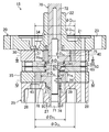
- FIG. 1 is a longitudinal sectional view of a rotary compressor.
- FIG. 2 is a longitudinal sectional view of a compression mechanism of the rotary compressor.
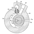
- FIG. 3 is a cross-sectional view of the compression mechanism showing the III-III cross section of FIG.
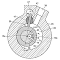
- FIG. 4 is a cross-sectional view of the compression mechanism showing the IV-IV cross section of FIG.
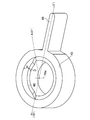
- FIG. 5 is a perspective view showing the lower surface side of the lower piston of the rotary compressor.
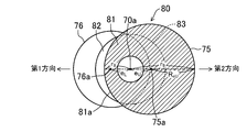
- FIG. 6 is a front view of the main part of the drive shaft of the rotary compressor.
- FIG. 7 is a longitudinal sectional view of an essential part of a drive shaft of the rotary compressor.
- FIG. 8 is a cross-sectional view of a drive shaft showing the AA cross section of FIG. FIG.
- FIG. 9 is a cross-sectional view of a drive shaft showing a cross section BB of FIG.
- FIG. 10 is a cross-sectional view of a drive shaft showing a cross section taken along the line CC of FIG.
- FIG. 11 is a cross-sectional view of a drive shaft showing a DD cross section of FIG.
- FIG. 12 is a cross-sectional view of a drive shaft showing the EE cross section of FIG.
- FIG. 13 is a cross-sectional view of a drive shaft showing the FF cross section of FIG.
- FIG. 14 is a cross-sectional view of a drive shaft showing a G-G cross section of FIG.
- FIG. 15 is a cross-sectional view of a drive shaft showing the HH cross section of FIG.
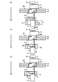
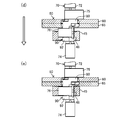
- FIG. 16A is a process diagram showing a process of attaching a lower piston to a drive shaft.
- FIG. 16B is a process diagram showing the process of attaching the lower piston to the drive shaft.
- Embodiment 1 of the Invention Embodiment 1 of the present invention will be described.
- the compressor of the present embodiment is a totally enclosed rotary compressor (1).
- a compression mechanism (15) and an electric motor (10) are accommodated in a casing (2).
- the rotary compressor (1) is provided in a refrigerant circuit that performs a vapor compression refrigeration cycle, and sucks and compresses refrigerant evaporated by the evaporator.
- the casing (2) is a cylindrical closed container in an upright state.
- the casing (2) comprises a cylindrical body (3) and a pair of end plates (4, 5) closing the end of the body (3).
- a suction pipe (not shown) is attached to the lower part of the body (3).
- a discharge pipe (6) is attached to the upper end plate (4).
- the motor (10) is disposed at the top of the internal space of the casing (2).
- the motor (10) comprises a stator (11) and a rotor (12).
- the stator (11) is fixed to the body (3) of the casing (2).
- the rotor (12) is attached to a drive shaft (70) of a compression mechanism (15) described later.
- the compression mechanism (15) is a so-called oscillating piston type rotary fluid machine. In the inner space of the casing (2), the compression mechanism (15) is disposed below the motor (10).
- the compression mechanism (15) is a two-cylinder rotary type fluid machine.
- the compression mechanism (15) includes one front head (20), one rear head (25), and one drive shaft (70).
- the compression mechanism (15) also includes two cylinders (30, 35), two pistons (40, 45), and two blades (41, 46). Each cylinder (30, 35) is provided with one pair of two bushes (42, 47).
- the compression mechanism (15) also includes an intermediate plate (50).
- the rear head (25), the lower cylinder (first cylinder) (35), the middle plate (50), and the upper cylinder (second cylinder) (30) sequentially from the bottom to the top.
- the front head (20) are arranged in an overlapping manner.
- the rear head (25), the lower cylinder (35), the middle plate (50), the upper cylinder (30), and the front head (20) are mutually fastened by a plurality of bolts not shown. Further, in the compression mechanism (15), the front head (20) is fixed to the body (3) of the casing (2).
- each cylinder (30, 35) is a thick disc-like member.
- the lower cylinder (35) constitutes a first cylinder and the upper cylinder (30) constitutes a second cylinder.
- Each cylinder (30, 35) is formed with a cylinder bore (31, 36), a blade accommodation hole (32, 37), and a suction port (33, 38). Further, the upper cylinder (30) and the lower cylinder (35) have the same thickness.
- each cylinder (30, 35) such as a through hole for inserting a bolt for assembling the compression mechanism (15), passes through each cylinder (30, 35). A plurality of through holes are formed in the thickness direction.
- the cylinder bores (31, 36) are circular holes penetrating the cylinder (30, 35) in the thickness direction, and are formed at the central portion of the cylinder (30, 35).
- An upper piston (second piston) (40) is accommodated in a cylinder bore (31) of the upper cylinder (30).
- the lower piston (first piston) (45) is accommodated in the cylinder bore (36) of the lower cylinder (35).
- Inner diameter [phi] D CL of the cylinder bore (36) of the cylinder bore and the inner diameter [phi] D CU (31), the lower cylinder (35) of the upper cylinder (30) are equal to each other (see FIG. 2).
- the blade accommodation hole (32, 37) is a hole extending radially outward of the cylinder (30, 35) from the inner peripheral surface of the cylinder (30, 35) (ie, the outer edge of the cylinder bore (31, 36)). is there.
- the blade receiving holes (32, 37) penetrate the cylinder (30, 35) in the thickness direction.
- the upper blade (41) is accommodated in the blade accommodation hole (32) of the upper cylinder (30).
- the lower blade (first blade) (46) is accommodated in the blade accommodation hole (37) of the lower cylinder (35).
- the blade accommodation hole (32, 37) is shaped such that the wall surface (a part of the cylinder (30, 35)) surrounding the blade accommodation hole (32, 37) does not interfere with the swinging blade (41, 46) It has become.
- the suction port (33, 38) has a circular cross section extending radially outward of the cylinder (30, 35) from the inner peripheral surface of the cylinder (30, 35) (ie, the outer edge of the cylinder bore (31, 36)) It is a hole of The suction port (33, 38) is disposed in the vicinity of the blade accommodation hole (32, 37) (in the present embodiment, to the right of the blade accommodation hole (32, 37 in FIGS. 3 and 4)) 30 and 35) open on the outside surface.
- An upper suction pipe (not shown) is inserted into the suction port (33) of the upper cylinder (30), and a lower suction pipe (not shown) is inserted into the suction port (38) of the lower cylinder (35) .
- Front head (20) is a member that closes an end face (upper end face in FIG. 2) on the electric motor (10) side of the upper cylinder (30).
- the front head (20) includes a main body (21), a main bearing (second bearing) (22), and an outer peripheral wall (23).
- the main body (21) is formed in a generally circular thick plate shape.
- the main body (21) is arranged to cover the end face of the upper cylinder (30).
- the lower surface of the main body (21) is in close contact with the upper cylinder (30).
- the main bearing portion (22) is formed in a cylindrical shape extending from the main body portion (21) to the electric motor (10) side (upper side in FIG. 1), and is disposed at the central portion of the main body portion (21).
- the main bearing portion (22) constitutes a journal bearing that supports the drive shaft (70) of the compression mechanism (15).
- the outer peripheral wall portion (23) is a thick annular portion formed continuously to the outer peripheral edge portion of the main body portion (21).
- a discharge port (24) is formed in the front head (20).
- the discharge port (24) penetrates the main body (21) of the front head (20) in the thickness direction.
- the discharge port (24) is a blade accommodation hole (32) of the upper cylinder (30). 3) in the vicinity opposite to the suction port (33) (in the present embodiment, to the left of the blade accommodation hole (32) in FIG. 3).
- a discharge valve for opening and closing the discharge port (24) is attached to the main body (21) of the front head (20).
- the rear head (25) is a member for closing the end surface (lower end surface in FIG. 1) of the lower cylinder (35) on the opposite side to the motor (10).
- the rear head (25) includes a main body (26), a sub bearing (first bearing) (27), and an outer peripheral wall (28).
- the main body (26) is formed in a generally circular thick plate shape.
- the main body (26) is arranged to cover the end face of the lower cylinder (35).
- the upper surface of the main body (26) is in close contact with the lower cylinder (35).
- the sub bearing portion (27) is formed in a cylindrical shape extending from the main body portion (26) to the opposite side (lower side in FIG. 2) to the lower cylinder (35), and is disposed at the central portion of the main body portion (26). Ru.
- the sub bearing (27) constitutes a journal bearing that supports the drive shaft (70) of the compression mechanism (15).
- the outer peripheral wall portion (28) is formed in a cylindrical shape extending from the outer peripheral edge portion of the main body portion (26) to the opposite side to the lower cylinder (35).
- the length (height) of the outer peripheral wall (28) is substantially equal to the length (height) of the auxiliary bearing (27).
- a discharge port (29) is formed in the rear head (25).
- the discharge port (29) penetrates the main body (26) of the rear head (25) in the thickness direction.
- the discharge port (29) on the upper surface of the main body (26) of the rear head (25) (the surface in contact with the lower cylinder (35)) It opens in the vicinity on the opposite side to the suction port (38) of 37) (in this embodiment, to the left of the blade accommodation hole (37) in FIG. 4).
- a discharge valve for opening and closing the discharge port (29) is attached to the main body (26) of the rear head (25).
- the middle plate (50) is composed of an upper plate member (60) and a lower plate member (65).
- the upper plate member (60) and the lower plate member (65) are generally circular flat members.
- Each of the upper plate member (60) and the lower plate member (65) partially protrudes radially outward.
- each plate member (60, 65) such as a through hole for inserting a bolt for assembling the compression mechanism (15) in each plate member (60, 65) in the thickness direction
- a plurality of through holes are formed through the through holes.
- the upper plate member (60) and the lower plate member (65) constitute an intermediate plate (50) by overlapping each other.
- the upper plate member (60) is disposed on the upper cylinder (30) side and covers an end surface (a lower surface in FIG. 2) of the upper cylinder (30).
- the upper surface of the upper plate member (60) is in close contact with the upper cylinder (30).
- the lower plate member (65) is disposed on the lower cylinder (35) side and covers an end surface (upper surface in FIG. 2) of the lower cylinder (35).
- the lower surface of the lower plate member (65) is in close contact with the lower cylinder (35).
- the upper surface of the lower plate member (65) is in close contact with the lower surface of the upper plate member (60).
- a central hole (51) passing through the middle plate (50) in the thickness direction is formed in the middle of the middle plate (50), ie, at the middle of the upper plate member (60) and the lower plate member (65). It is done.
- a drive shaft (70) is inserted through the central hole (51) of the intermediate plate (50).
- An upper annular convex portion (62) projecting annularly toward the central hole (51) is formed on the upper end portion of the inner peripheral portion of the upper plate member (60), and the inner peripheral portion of the lower plate member (65)
- a lower annular convex portion (67) projecting annularly toward the central hole (51) is formed at the lower end portion of the lower ring portion.
- the upper end portion and the lower end portion of the central hole (51) are formed to have a diameter smaller than that of the middle portion by the upper annular convex portion (62) and the lower annular convex portion (67).
- the diameters of the upper end portion and the lower end portion of the central hole (51) are equal to ⁇ D o
- the diameter ⁇ D o of the upper end portion and the lower end portion of the central hole (51) is a lower eccentric portion 76) is larger than the outer diameter ⁇ D eL and smaller than the outer diameter ⁇ D eU of the upper eccentric portion (75) ( ⁇ D eL ⁇ D o ⁇ D eU ).
- the drive shaft (70) includes a main shaft portion (second shaft portion) (72), an upper eccentric portion (second eccentric portion) (75), and an intermediate connection portion (80). , A lower eccentric portion (first eccentric portion) (76), a lower connecting portion (first connecting portion) (90), and a sub shaft portion (first shaft portion) (74).
- first shaft portion first shaft portion
- the main shaft portion (72), the upper eccentric portion (75), the intermediate connection portion (80), the lower eccentric portion (76), the lower connection portion (90), and the auxiliary shaft The parts (74) are arranged in order from the top to the bottom.
- the main shaft portion (72), the upper eccentric portion (75), the intermediate connection portion (80), the lower eccentric portion (76), the lower connection portion (90), and the auxiliary shaft The parts (74) are integrally formed with each other.
- the main shaft portion (72) and the sub shaft portion (74) are columnar or rod-like portions of circular cross section.
- the rotor (12) of the motor (10) is attached to the top of the main shaft (72).
- the lower part of the main shaft (72) constitutes a journal supported by the main bearing (22) of the front head (20), and the sub shaft (74) is formed by the sub bearing (27) of the rear head (25) Construct a supported journal.
- the outer diameter of the countershaft (74) is smaller than the outer diameter of the main shaft (72). Assuming that the radius of the main shaft portion (72) is R M (the radius R 2 of the second shaft portion) and the radius of the sub shaft portion (74) is R S (the radius R 1 of the first shaft portion) ) Is configured such that 2R S ⁇ 2R M.
- Each eccentric portion (75, 76) is a cylindrical portion having a diameter larger than that of the main shaft portion (72).
- the upper eccentric portion (75) constitutes a second eccentric portion
- the lower eccentric portion (76) constitutes a first eccentric portion.
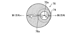
- the central axis (75a, 76a) is eccentric with respect to the rotational central axis (70a) of the drive shaft (70) (see FIG. 6).
- the upper eccentric portion (75) is eccentric to the side opposite to the lower eccentric portion (76) with respect to the rotation center axis (70a) of the drive shaft (70).
- the outer diameter ⁇ D eL of the lower eccentric portion (76) is smaller than the outer diameter ⁇ D eU of the upper eccentric portion (75) ( ⁇ D eL ⁇ D eU ).
- the middle connection part (80) is disposed between the upper eccentric part (75) and the lower eccentric part (76), and connects the upper eccentric part (75) and the lower eccentric part (76).
- the lower connecting portion (90) is disposed between the lower eccentric portion (76) and the countershaft portion (74), and connects the lower eccentric portion (76) and the countershaft portion (74).
- An oil supply passage (71) is formed in the drive shaft (70) (see FIG. 2).
- the lubricating oil accumulated at the bottom of the casing (2) is supplied to the bearing of the drive shaft (70) and the sliding portion of the compression mechanism (15) through the oil supply passage (71).
- each piston (40, 45) is a slightly thick cylindrical member.
- the upper piston (40) constitutes a second piston and the lower piston (45) constitutes a first piston.
- the outer diameter [phi] D PU upper piston (40), an outer diameter [phi] D PL of the lower piston (45) equal to each other.
- the inner diameter of the lower piston (45) is smaller than the inner diameter of the upper piston (40).
- the radial thickness of the lower piston (45) is greater than the radial thickness of the upper piston (40).
- the upper eccentric portion (75) of the drive shaft (70) is rotatably fitted in the upper piston (40).
- the outer peripheral surface slides with the inner peripheral surface of the upper cylinder (30), one end surface slides with the lower surface of the main body (21) of the front head (20), and the other end surface It slides on the upper surface of the upper plate member (60) of the middle plate (50).
- a compression chamber (second compression chamber) (34) is formed between the outer peripheral surface of the upper piston (40) and the inner peripheral surface of the upper cylinder (30).
- the lower eccentric portion (76) of the drive shaft (70) is rotatably fitted in the lower piston (45).
- the outer peripheral surface slides with the inner peripheral surface of the lower cylinder (35), one end surface slides with the upper surface of the main body (21) of the rear head (25), and the other end surface Slides on the lower surface of the lower plate member (65) of the middle plate (50).
- a compression chamber (first compression chamber) (39) is formed between the outer peripheral surface of the lower piston (45) and the inner peripheral surface of the lower cylinder (35).
- the lower piston (45) is formed with an inner circumferential groove (48).
- an inner circumferential groove (48) is formed with an inner circumferential groove (48).
- the inner circumferential groove (48) is an elongated recess formed on the inner circumferential surface of the lower piston (45) along a part of the inner circumferential surface in the circumferential direction.
- the inner circumferential groove (48) is formed along the lower end of the inner peripheral surface of the lower piston (45) and opens at the lower end of the lower piston (45) in FIG.
- the inner circumferential groove (48) of the lower piston (45) has a maximum value (maximum depth) of depth (radial length of the lower piston (45)) of "D", and a height (lower The length in the central axis direction of the side piston (45) is "H" (see FIGS. 2, 5 and 16A).
- the blades (41, 46) are rectangular flat members.
- the upper blade (41) is integrally formed with the upper piston (40)
- the lower blade (46) is integrally formed with the lower piston (45).
- Each blade (41, 46) protrudes radially outward of the piston (40, 45) from the outer side surface of the corresponding piston (40, 45).
- the width (axial length of the pistons (40, 45)) of each blade (41, 46) is equal to the height (H PU , H PL ) of the corresponding piston (40, 45).
- the respective blades (41, 46) have equal overall lengths (radial lengths of the pistons (40, 45)).
- the upper blade (41) integral with the upper piston (40) fits into the blade receiving hole (32) of the upper cylinder (30).
- the upper blade (41) divides the compression chamber (34) formed in the upper cylinder (30) into a low pressure chamber on the suction port (33) side and a high pressure chamber on the discharge port (24) side.
- the lower blade (46) integral with the lower piston (45) fits in the blade receiving hole (37) of the lower cylinder (35).
- the lower blade (46) divides the compression chamber (39) formed in the lower cylinder (35) into a low pressure chamber on the suction port (38) side and a high pressure chamber on the discharge port (29) side.
- Each of the upper cylinder (30) and the lower cylinder (35) is provided with a pair of bushes (42, 47).
- Each of the bushes (42, 47) is a small plate-like member whose front surfaces facing each other are flat surfaces and whose rear surfaces are arc surfaces.
- the pair of bushes (42) provided in the upper cylinder (30) are disposed so as to sandwich the upper blade (41) fitted in the blade accommodation hole (32) of the upper cylinder (30) from both sides.
- the upper blade (41) integral with the upper piston (40) is swingably supported by the upper cylinder (30) via the bush (42).
- the pair of bushes (47) provided in the lower cylinder (35) are arranged to sandwich the lower blade (46) fitted in the blade accommodation hole (37) of the lower cylinder (35) from both sides Ru.
- the lower blade (46) integral with the lower piston (45) is swingably supported by the lower cylinder (35) via the bush (47).
- the lower piston (45) is moved to the inside of the lower cylinder (35) as the drive shaft (70) rotates by the pair of bushes (47) and the lower blade (46).
- the rocking piston is configured to rock with respect to the central axis (76a) of the lower eccentric portion (76) while revolving along the wall surface.
- the drive shaft (70) includes the main shaft (72), the upper eccentric (75), the intermediate connection (80), the lower eccentric (76), and the lower connection (90). And a countershaft (74).
- the detailed structure of the drive shaft (70) will be described with reference to FIGS. Note that “right” and “left” in this description mean “right” and “left” in FIGS. 6 to 15, respectively. 6 to 15, “left” is a first direction which is an eccentric direction of the lower eccentric part (76) which is a first eccentric part, and “right” is a second eccentric part. This is a second direction which is an eccentric direction of an upper eccentric portion (75).
- each of the main shaft portion (72) and the sub shaft portion (74) is a columnar or rod-like portion of a circular cross section.
- the central axis of the main shaft portion (72) and the central axis of the auxiliary shaft portion (74) coincide with the rotational central axis (70a) of the drive shaft (70).
- the outer diameter of the main shaft (72) is substantially constant over the entire length of the main shaft (72).
- the outer diameter of the countershaft (74) is substantially constant along the entire length of the countershaft (74). As shown in FIGS. 6 and 7, the outer diameter of the countershaft (74) is slightly smaller than the outer diameter of the main shaft (72).
- the radius of the main shaft portion (72) is R M (the radius R 2 of the second shaft portion) and the radius of the sub shaft portion (74) is R S (the radius R 1 of the first shaft portion) ) Is configured such that 2R S ⁇ 2R M.
- an upper oil supply groove (73) is formed by slightly constricting an end (lower end in FIG. 6) connected to the upper eccentric portion (75). Lubricant oil is supplied from the oil supply passage (71) to the upper oil supply groove (73).
- each of the upper eccentric portion (75) and the lower eccentric portion (76) is a cylindrical portion having a diameter larger than that of the main shaft portion (72).
- the outer diameter ⁇ D eL of the lower eccentric portion (76) is smaller than the outer diameter ⁇ D eU of the upper eccentric portion (75) ( ⁇ D eL ⁇ D eU ).
- the upper eccentric portion (75) and the lower eccentric portion (76) have substantially the same height (i.e., the length of the drive shaft (70) in the direction of the central axis of rotation (70a)).
- the height of the upper eccentric portion (75) is slightly lower than the height H PU of the upper piston (40)
- the height of the lower eccentric portion (76) is the height H PL of the lower piston (45) Slightly lower than.
- the upper eccentric portion (75) is opposite to the first direction when the eccentric direction of the lower eccentric portion (76) is the first direction with respect to the rotation center axis (70a) of the drive shaft (70). It is eccentric in the second direction of the direction. That is, the eccentric direction of the upper eccentric portion (75) with respect to the rotation center axis (70a) of the drive shaft (70) is the eccentric direction of the lower eccentric portion (76) with respect to the rotation center axis (70a) of the drive shaft (70) 180 degrees different.
- the eccentricity e U of upper eccentric portion (75) is the distance of the upper eccentric portion central axis of (75) (75a) and the axis of rotation of the drive shaft (70) and (70a).
- the eccentric amount e L of the lower eccentric portion (76) is the distance between the central axis (76a) of the lower eccentric portion (76) and the rotational central axis (70a) of the drive shaft (70).
- the distance r 3 is less than the radius R S of the auxiliary shaft portion (74).
- r 8 is from the central axis of rotation (70a) of the drive shaft (70).
- the distance r 8 the radius R M is substantially equal to the main shaft portion (72).
- the lower connecting portion (90) is a portion disposed between the countershaft (74) and the lower eccentric portion (76). As shown in FIGS. 6 to 9, the lower connecting portion (90) has a main body (91) and a reinforcing portion (92). The main body (91) and the reinforcement (92) are integrally formed.
- the main body (91) is coaxial with the rotation center axis (70a) of the drive shaft (70) continuously formed above the countershaft (74) and has a radius It is a substantially cylindrical portion of R S (R 1 ), which is the same as the countershaft portion (74).
- the main body (91) is partially cut away in the second direction so as not to protrude outward from the outer peripheral surface of the lower eccentric portion (76) in the radial direction of the drive shaft (70).
- a part of the main body (91) on the second direction side has a central axis coincident with the central axis (76a) of the lower eccentric part (76) and a radius of the lower eccentric part (76).
- a portion (circular arc surface) of a cylindrical surface equal to the radius R eL is cut out (see FIGS. 8 and 9).
- the outer surface (91a) on the second direction side of the main body (91) has a central axis coincident with the central axis (76a) of the lower eccentric part (76) and a radius of the lower eccentric part (76). It is constituted by a part of a cylindrical surface (arc surface) equal to the radius R eL .
- the end (lower end in FIG. 6) connected to the countershaft (74) is narrower than the countershaft (74).
- the lower oil supply groove (93) is formed.
- the lower oil supply groove (93) is formed over the entire circumference of the drive shaft (70), and lubricating oil is supplied from the oil supply passage (71).
- the reinforced portion (92) is a portion which bulges in the first direction from the outer peripheral portion of the main body portion (91) formed above the lower side oil supply groove (93) of the main body portion (91) (FIG. 7 and See Figure 9).
- the reinforcing portion (92) is formed such that the outer surface (92a, 92b) does not protrude outward from the outer peripheral surface of the lower eccentric portion (76) in the radial direction of the drive shaft (70).
- the outer surface (92 a, 92 b) is formed to be located outside the outer peripheral surface of the sub shaft portion (74) in the radial direction of the drive shaft (70).
- the outer surface (92a, 92b) of the reinforcing portion (92) has a central axis coincident with the central axis (76a) of the lower eccentric portion (76) and a radius at the lower side.
- Part of the cylinder surface (arc surface) equal to the radius R eL of the eccentric part (76) and part of the cylinder surface of radius r 2 whose central axis coincides with the rotation center axis (70a) of the drive shaft (70) And the face).
- the right side surface (92a) on the second direction side (right side in FIG. 9) of the outer surfaces (92a, 92b) of the reinforced portion (92) has a central axis that is the central axis (76a) of the lower eccentric portion (76). And a portion of a cylindrical surface (arc surface) having a radius equal to the radius ReL of the lower eccentric portion (76).
- the minimum value r 1 of the distance to the right side surface (92a) of the reinforced portion from the rotation center axis (70a) of the drive shaft (70) (92) is smaller than the radius R S of the auxiliary shaft portion (74) (r 1 ⁇ R S ).
- the maximum value of the distance from the rotation center axis (70a) of the drive shaft (70) to the right side surface (92a) of the reinforced portion (92) is a part of the cylindrical surface constituting the left side surface (92b) Is equal to the radius r 2 of the arc surface) and larger than the radius R S of the minor shaft (74) (r 2 > R S ).
- the middle portion in the circumferential direction is positioned inside the outer peripheral surface of the countershaft portion (74), and the middle portion in the circumferential direction
- the other side portions are configured to be located outside the outer peripheral surface of the countershaft (74).
- the minimum value r 1 of the distance to the right side surface (92a) of the reinforced portion from the rotation center axis (70a) of the drive shaft (70) (92), the central axis of rotation of the drive shaft (70) (70a ) substantially equal to the minimum value r 3 of the distance to the outer peripheral surface of the lower eccentric portion (76) from. That is, the right side surface (92 a) is formed so as not to protrude outward from the outer peripheral surface of the lower eccentric portion (76) in the radial direction of the drive shaft (70).
- the distance r 1 for this reinforced portion (92) may be any distance r 3 or less about the lower eccentric portion (76) (r 1 ⁇ r 3).
- the left side surface (92b) on the first direction side (left side in FIG. 9) has a central axis that is the central axis of rotation (70a) of the drive shaft (70). And a part (circular arc surface) of the cylindrical surface of the radius r 2 which corresponds to. Radius r 2 of the left side surface (92b) is greater than the radius R S of the auxiliary shaft portion (74) (r 2> R S). Further, the left side surface (92 b) is formed so as not to protrude outward from the outer peripheral surface of the lower eccentric portion (76) in the radial direction of the drive shaft (70).
- the left side surface (92 b) is formed so as not to protrude outward from the outer peripheral surface of the lower eccentric portion (76) in the radial direction of the drive shaft (70) and the outer peripheral surface of the sub shaft portion (74) It is formed to be located on the outer side than the other.
- the outer surface of the lower eccentric portion (76) in the radial direction of the drive shaft (70) is located between the lower eccentric portion (76) of the drive shaft (70) and the auxiliary shaft portion (74).
- a lower connecting portion (first connecting portion) (90) is formed so as not to protrude outward from the outer peripheral surface.
- H CL shown in FIG. 7 is the height of the lower connecting portion (90) (that is, the length of the drive shaft (70) in the direction of the rotation center axis (70a)), and the lower connecting portion (90)
- the height H CL of H is substantially equal to the distance from the upper end of the countershaft (74) to the lower end of the lower eccentric part (76) in FIG.
- the height h 1 of the reinforced portion (92) is higher than the half height of the lower connection portion (90) (h 1 > H CL / 2).
- the lower connection portion (90) is formed such that the height H CL is lower than the height H PL of the lower piston (45) (H CL ⁇ H PL ).
- the lower piston (45) when the lower piston (45) is externally fitted to the lower eccentric part (76) from the side of the countershaft (74), the lower piston (45) is connected to the lower connecting part (90)
- the height H CL of the lower connecting portion (90) is higher than the height H PL of the lower piston (45) in order to shift the outer periphery of the lower connecting portion (76) to a position where it can be externally fitted to the lower eccentric portion (76).
- the height H of the lower piston (45) is larger than “the difference between the height H PL of the lower piston (45) and the height H CL of the lower connecting portion (90)”.
- the height H is "the difference between the height H PL of the lower piston (45) and the height H CL of the lower connection portion (90)”
- the height H CL of the lower connecting portion (90) is greater than the height H PL of the lower piston (45) Is also formed low. Details will be described later.
- the intermediate connection portion (80) is a portion disposed between the upper eccentric portion (75) and the lower eccentric portion (76).
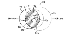
- the middle connecting portion (80) is composed of the main body (81), the lower middle reinforcement (first middle reinforcement) (82) and the upper middle reinforcement And a second intermediate reinforcing portion (83).
- the main body (81), the lower middle reinforcement (82) and the upper middle reinforcement (83) are integrally formed. Further, as shown in FIGS. 6 and 7, the lower middle reinforcement portion (82) and the upper middle reinforcement portion (83) are formed so as to partially overlap in the axial direction of the drive shaft (70).
- the main body (81) is formed between the upper eccentric portion (75) and the lower eccentric portion (76) between the upper eccentric portion (75) and the lower eccentric portion (76).
- 76) is a columnar portion where the two extensions overlap when the two extend each other.
- the right side surface (81b) on the second direction side (right side in FIG. 11) has a central axis that is the center of the lower eccentric portion (76).
- a portion (arc surface) of a cylindrical surface having a radius ReL of the lower eccentric portion (76) is formed, which coincides with the axis (76a).
- the left side (81a) on the first direction side (left side in FIG. 14) has a central axis that is the central axis (75a) of the upper eccentric part (75) And a portion of a cylindrical surface (arc surface) having a radius equal to the radius R eU of the upper eccentric portion (75).
- the lower intermediate reinforcing portion (82) is provided adjacent to the lower eccentric portion (76), and is a portion bulging from the outer peripheral portion of the main body portion (91) in the first direction (FIG. 7, FIG. 7) 11 to 13).
- the lower intermediate reinforcement portion (82) is a part of a cylindrical surface of radius r 5 (the outer surface (82a) has a center axis coinciding with the rotation center axis (70a) of the drive shaft (70) Is made up of
- the radius r 5 of the arc surface is greater than the minimum value r 8 of the distance to the outer peripheral surface of the upper eccentric portion from the rotation center axis (70a) of the drive shaft (70) (75), rotation of the drive shaft (70) central axis lower eccentric portion from (70a) (76) smaller than the maximum value r 4 of the distance to the outer peripheral surface of the (r 8 ⁇ r 5 ⁇ r 4).
- the lower intermediate reinforcing portion (82) is formed in the region on the first direction side, and the outer surface (82a) is the outer peripheral surface of the lower eccentric portion (76) in the radial direction of the drive shaft (70). It is formed so as to be positioned more inside than the outer peripheral surface of the upper eccentric portion (75).
- H CM shown in FIG. 7, the height of the intermediate connecting portion (80) (i.e., the central axis of rotation of the drive shaft (70) (70a) the length direction), and an intermediate connecting portion (80) High
- the height H CM is substantially equal to the distance from the upper end of the lower eccentric (76) to the lower end of the upper eccentric (75) in FIG.
- the height h 2 of the lower intermediate reinforcing portion (82) is higher than half the height of the intermediate connecting portion (80) (h 2> H CM / 2).
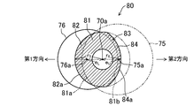
- the upper middle reinforcement portion (83) is provided adjacent to the upper eccentric portion (75), and is a portion which bulges in the second direction from the outer peripheral portion of the main body portion (91) (FIG. 7, FIG. 12 See Figure 14).
- the upper middle reinforcement portion (83) has a smaller amount of expansion from the outer peripheral portion of the main body (91) than the lower small expanded portion (84) and an amount of expansion from the outer peripheral portion of the main body (91)
- the upper bulging portion (85) is larger than the bulging portion (84).
- the large bulging portion (85) is adjacent to the upper eccentric portion (75) in the axial direction of the drive shaft (70), and the small bulging portion (84) is adjacent to the large bulging portion (85).
- the small bulging portion (84) of the upper middle reinforcement portion (83) has an outer surface (84a) whose center axis coincides with the center axis (76a) of the lower eccentric portion (76). And it is comprised by a part (arc surface) of the cylindrical surface whose radius is larger than radius ReL of lower side eccentric part (76). As shown in FIG. 12, the small bulging portion (84) of the upper middle reinforcement portion (83) has an outer surface (84a) whose center axis coincides with the center axis (76a) of the lower eccentric portion (76). And it is comprised by a part (arc surface) of the cylindrical surface whose radius is larger than radius ReL of lower side eccentric part (76). As shown in FIG.
- the large bulging portion (85) of the upper intermediate reinforcement portion (83) has a radius r such that the outer surface (85a) has a central axis coincident with the rotational central axis (70a) of the drive shaft (70) It is composed of a part of the cylindrical surface of 7 (arc surface).
- the upper intermediate reinforcing portion (83) is formed in the region on the second direction side, and the outer surface (84a, 85a) is the outer peripheral surface of the upper eccentric portion (75) in the radial direction of the drive shaft (70). It is formed to be positioned more inside and outside the outer peripheral surface of the lower eccentric portion (76).
- the height h 3 of the upper intermediate reinforcing portion (83) is higher than half the height of the intermediate connecting portion (80) (h 3> H CM / 2).
- the height h 4 of the small bulging portion of the upper intermediate reinforcing portion (83) (84) is lower than the height h 5 of the large swollen portions (85) (h 4 ⁇ h 5).
- the heights h 2 and h 3 of the lower middle reinforcement portion (82) and the upper middle reinforcement portion (83) are both higher than the height of half of the middle connection portion (80). That is, the lower middle reinforcement portion (82) and the upper middle reinforcement portion (83) are formed to partially overlap in the axial direction of the drive shaft (70). Then, as shown in FIGS. 6, 7 and 13, the lower intermediate reinforcement portion (82) and the large bulging portion (85) of the upper intermediate reinforcement portion (83) extend in the axial direction of the drive shaft (70).
- the middle overlapping portion (86) of the middle connecting portion (80) partially overlapping is formed in a cylindrical shape coaxial with the rotation center axis (70a) of the drive shaft (70).
- the outer surface of the overlapping portion (86) is an outer surface (82a) of the lower intermediate reinforcement (82) and an outer surface (85a) of the large bulging portion (85) of the upper intermediate reinforcement (83).
- the cross section is formed in a circular shape centered on the rotation center axis (70a) of the drive shaft (70).
- the outer surface of the outer surface radius r 5 and the upper middle reinforced portion of the arcuate surface which defines the (82a) large swollen portion (83) (85) of the lower intermediate reinforcing portion (82) (85a)
- the inner circumferential groove (48) extending in the circumferential direction is formed on the inner circumferential surface of the lower piston (45).
- the inner peripheral groove (48) is an end portion on the lower connecting portion (90) side in the axial direction of the drive shaft (70) on the inner peripheral surface of the lower piston (45), ie, FIG.
- the lower piston (45) is formed along the lower end of the inner peripheral surface of the lower piston (45), and opens at the lower end of the lower piston (45) in FIG. 16A.
- the inner circumferential groove (48) is formed on a part of the inner circumferential surface of the lower piston (45) in the circumferential direction.
- the inner circumferential groove (48) is a lower side in the installation position of the lower blade (46), ie, the circumferential direction of the lower piston (45), on the inner circumferential surface of the lower piston (45) It is formed in the range of a half circumference of the suction side (the suction port (38) side) from the position where the blade (46) is provided.
- the inner circumferential groove (48) extends in the extension direction of the lower blade (46) with respect to the central axis (76a) of the lower eccentric portion (76) in the circumferential direction of the lower piston (45)
- the angular position of the center line L is 0 °
- the angular position A advanced 30 ° from the angular position (0 °) in the rotational direction of the drive shaft (70) is the starting point, and from the angular position (0 °)
- An angular position B advanced by 180 ° in the rotational direction of the drive shaft (70) is formed to be an end point. That is, the inner circumferential groove (48) is formed on the inner circumferential surface of the lower piston (45) from the angular position A of 30 ° to the angular position B of 180 °.
- the inner circumferential groove (48) has the maximum value (maximum depth) D of the depth (the length in the radial direction of the lower piston (45)) and the radius R S of the sub shaft (74) and the lower side greater than the difference between the distance r 3 about the eccentric portion (76) (D> R S - (R eL -e L)), ( the central axis direction of the length of the lower piston (45)) the height H is, It is formed to be larger than the difference (H PL -H CL ) between the height H PL of the lower piston (45) and the height H CL of the lower connection portion (90).
- the inner circumferential groove (48) is formed in a cross-sectional shape that can include a portion that protrudes from the outer surface of the lower eccentric portion (76) of the lower shaft portion (74) when viewed from the axial direction of the drive shaft (70). ing.
- the outer peripheral surface of the lower eccentric portion (76) and the lower piston (45) are provided by thus providing the inner peripheral groove (48) on the inner peripheral surface of the lower piston (45).
- the mechanical loss is reduced by reducing the viscous shear loss of the lubricating oil on the sliding surface with the inner circumferential surface of.
- seizure or wear is caused. There is no risk of
- the formation position is not necessarily the inner circumferential surface of the lower piston (45). It does not have to be at the bottom.
- the inner circumferential groove (48) when the inner circumferential groove (48) is attached to the drive shaft (70) of the lower piston (45), the inner circumferential groove (45) can also be used to avoid catching the lower piston (45). 48) at the lower end of the inner circumferential surface of the lower piston (45), and the maximum depth D and height H are the above-mentioned sizes and the cross-sectional shape as described above. ing.
- the height H CL of the lower connecting portion (90) is formed smaller than the height H PL of the lower piston (45).
- the drive shaft (on the outer periphery of the lower connecting part (90)) 70) when moving in the radial direction the upper end corner portion of the sub shaft portion (74) enters the inner circumferential groove (48) when the upper end corner portion on the second direction side of the sub shaft portion (74) enters.
- the lower piston (45) can be shifted to a position where it can be externally fitted to the lower eccentric portion (76) without being caught on the inner peripheral surface of the lower piston (45).
- the detailed attachment process of a lower side piston is mentioned later.
- the upper piston (40) is moved downward from the end on the main shaft (72) side of the drive shaft (70) and attached to the upper eccentric part (75). Subsequently, the upper cylinder (30) is disposed above the upper plate member (60), and the front head (20) is disposed above the upper cylinder (30). Then, the front head (20), the upper cylinder (30), the upper plate member (60), the lower plate member (65), the lower cylinder (35), and the rear head (25) in a stacked state are not shown. Fasten with multiple bolts.
- the lower piston (45) is moved to the first direction side (left side in FIG. 16A) which is the eccentric direction of the lower eccentric portion (76) on the outer periphery of the lower connecting portion (90) (FIG. 16A (c )reference).
- the lower piston (45) can be externally fitted to the lower eccentric portion (76) (the lower piston in the radial direction of the drive shaft (70)
- the inner peripheral surface of (45) is moved to the position where it is located outside the outer peripheral surface of the lower side eccentric part (76).
- the inner circumferential groove (48) formed on the inner circumferential surface of the lower piston (45) is located on the second direction side (right side in FIG. 16A) which is the anti-eccentric direction of the lower eccentric portion (76).
- the lower piston (45) is turned so that In this state, the lower piston (45) is moved to the first direction side (left side in FIG. 16A) which is the eccentric direction of the lower eccentric portion (76).
- the upper end corner portion that protrudes outward beyond the lower connection portion (90) on the second direction side of the sub shaft portion (74) is the inner circumferential groove (48) of the lower piston (45).
- the lower piston (45) can be moved to the lower eccentric part (76) without the upper end corner part on the second direction side of the countershaft (74) being caught on the inner peripheral surface of the lower piston (45). It can be moved to a position where it can be externally fitted.
- a suction stroke for sucking the refrigerant from the suction port (33, 38) to the compression chamber (34, 39) and compression for compressing the refrigerant sucked into the compression chamber (34, 39) A stroke and a discharge step of discharging the compressed refrigerant from the discharge port (24, 29) to the outside of the compression chamber (34, 39) are performed.
- the refrigerant compressed in the compression chamber (34) of the upper cylinder (30) is discharged to the space above the front head (20) through the discharge port (24) of the front head (20).
- the refrigerant compressed in the compression chamber (39) of the lower cylinder (35) is discharged from the compression chamber (39) through the discharge port (29) of the rear head (25) and formed in the compression mechanism (15) It flows into the space above the front head (20) through a passage (not shown).
- the refrigerant discharged from the compression mechanism (15) to the internal space of the casing (2) flows out of the casing (2) through the discharge pipe (6).
- lubricating oil is stored at the bottom of the casing (2).
- the lubricating oil is supplied to the compression mechanism (15) through the oil supply passage (71) formed in the drive shaft (70), and is supplied to the sliding point of the compression mechanism (15).
- the lubricating oil is formed between the main bearing portion (22) and the sub bearing portion (27) and the drive shaft (70), the outer peripheral surface of the eccentric portion (75, 76) and the inner periphery of the piston (40, 45) It is supplied between the faces etc. Also, part of the lubricating oil flows into the compression chamber (34, 39) and is used to improve the airtightness of the compression chamber (34, 39).
- the pressure in the internal space of the casing (2) is substantially equal to the pressure of the high pressure refrigerant discharged from the compression mechanism (15). For this reason, the pressure of the lubricating oil stored in the casing (2) is also substantially equal to the pressure of the high pressure refrigerant discharged from the compression mechanism (15). Therefore, high pressure lubricating oil is supplied to the compression mechanism (15).
- the intermediate connection (80) of the drive shaft (70) rotates in the central hole (51) of the intermediate plate (50) filled with lubricating oil.
- the lower eccentric portion (76) radius R lower eccentric portion from eU (76) eccentricity e U a reduced length of, i.e., the rotation center axis of the drive shaft (70) ( 70a) to the outer surface in the second direction (anti-eccentric direction) of the lower eccentric portion (76) (from the rotation center axis (70a) of the drive shaft (70) to the outer surface of the lower eccentric portion (76)
- the minimum length r 3 ) is configured to be smaller than the radius R M of the countershaft (74).
- the outer surface of the lower eccentric portion (76) on the second direction side (anti-eccentric side) is against the outer surface on the second direction side (anti-eccentric side) of the auxiliary shaft portion (74).
- the capacity can be increased without increasing the sliding loss between the lower cylinder (35) and the lower piston (45).
- the lower piston (45) is viewed from the sub shaft (74) side.
- the lower piston (45) abuts on the axial end face of the lower eccentric portion (76)
- the lower piston (45) can not be attached to the lower eccentric (76) because it can not be moved in the direction.
- the outer surface of the lower eccentric portion (76) and the sub-shaft portion (74) extends outward from the outer surface of the lower eccentric portion (76) in the radial direction of the drive shaft (70). It decided to provide the lower side connection part (90) formed so that it might not stick out.
- the lower connecting portion (90) when assembling the lower piston (45) to the lower eccentric portion (76), the lower piston (45) is attached to the lower eccentric portion (76). A space for shifting to the position where it can be fitted is secured. That is, in the above rotary compressor (1), when the lower piston (45) is moved from the side of the countershaft (74) in the axial direction of the drive shaft (70) and externally fitted to the lower eccentric portion (76).
- the inner peripheral surface of the lower piston (45) can be shifted to the position located outside the outer peripheral surface of the lower eccentric part (76) in the radial direction of
- the lower piston (45) is moved again in the axial direction of the drive shaft (70) to lower the lower piston.
- (45) can be attached to the lower eccentric (76). That is, according to the first embodiment, the lower piston (45) is assembled to the lower eccentric portion (76) even if only the amount of eccentricity is increased without increasing the diameter of the lower eccentric portion (76). be able to.
- the lower connecting portion (90) thus formed so that the outer surface does not protrude outward from the outer surface of the lower eccentric portion (76) is the lower cylinder (35) which constitutes the sub bearing portion (27). Does not abut the rear head (end plate) (25) of That is, of the inner peripheral surface corresponding to the outer peripheral surface of the drive shaft (70) of the rear head (25), the portion corresponding to the lower connecting portion (90) does not function as a bearing, and constitutes the secondary bearing (27) do not do. Therefore, if the lower connection portion (90) is formed large, the sub-bearing portion (27) functioning as a bearing in the rear head (25) becomes smaller by that amount, and the load capacity of the bearing is lowered.
- the height H CL of the lower connecting portion (90) is formed smaller than the height H PL of the lower piston (45). Therefore, the part which does not function as a bearing in a rear head (25) becomes small, and it can control the fall of the load capacity of a bearing. Therefore, the reduction in the reliability of the rotary compressor (1) can be suppressed.
- the lower piston (45) is moved from the side of the countershaft (74) to the drive shaft (70).
- the diameter of the drive shaft (70) on the outer periphery of the lower connecting portion (90) as described above When moving in the direction, the corner on the lower connecting portion (90) side is caught on the inner circumferential surface of the lower piston (45) on the second direction side (anti-eccentric side) of the sub shaft (74), The side piston (45) can not be moved further in the radial direction, and the lower piston (45) can not be shifted to a position where it can be externally fitted to the lower eccentric portion (76).
- the height H of the first piston (in the axial direction of the drive shaft (70) on the inner peripheral surface of the lower piston (45) is lower than that of the first piston (H).
- 45) is greater than a value obtained by subtracting the height H C1 of the first connection portion (90) from the height H P1 of the first connection portion (90), and the lower side of the sub shaft portion (74) when viewed from the axial direction of the drive shaft (70)
- An inner peripheral groove (48) extending in the circumferential direction of a cross-sectional shape capable of containing a portion protruding from the outer surface of the eccentric portion (76) is formed.
- the lower piston (45) is assembled to the lower eccentric portion (76) while being moved in the axial direction of the drive shaft (70) from the side of the sub shaft (74). 45) when moving the radial direction of the drive shaft (70) on the outer periphery of the lower connection portion (90), the lower connection portion (90) on the second direction side (anti-eccentric side) of the sub shaft portion (74). Of the lower eccentric portion (76) in the radial direction of the drive shaft (70), and the lower piston (45) enters the inner circumferential groove (48). I will not scratch on the inner surface of).
- the lower piston (45) can be shifted to a position where it can be externally fitted to the lower eccentric portion (76) on the outer periphery of the lower connecting portion (90). That is, the lower piston (45) is attached to the lower eccentric portion (76) even if the height H CL of the lower connecting portion (90) is smaller than the height H PL of the lower piston (45). be able to.
- the inner circumferential groove (48) is formed on a part of the inner circumferential surface of the lower piston (45) not in the entire circumference but in the circumferential direction.
- the inner circumferential groove (48) is provided with a drive shaft (70) at the outer periphery of the lower connection portion (90).
- the lower piston (45) may have a size that can accommodate a portion protruding from the outer surface of the lower connecting portion (90) in the second direction when moving in the radial direction of It is not necessary to form over the entire circumference of the inner peripheral surface of.
- the inner circumferential groove (48) is formed by forming the inner circumferential groove (48) only on a portion of the inner circumferential surface of the lower piston (45), not on the entire circumference but in the circumferential direction. It is possible to suppress a decrease in strength of the side piston (45).
- the rotary compressor (1) is moved downward while the lower piston (45) revolves along the inner wall surface of the lower cylinder (35) as the drive shaft (70) rotates.
- the rotary compressor (1) of the so-called rocking piston type is configured to rock with respect to the central axis (76a) of the side eccentric portion (76).
- the lower piston (45) only swings without rotating, so the central axis of rotation (70a) of each part of the lower piston (45) The angular position relative to) does not vary significantly.
- the lower piston (45) is pressed against the lower eccentric portion (76) by the compressed fluid of the compression chamber (39) formed on the outer side, and the inner peripheral surface is the outer peripheral surface of the lower eccentric portion (76)
- a low pressure chamber with low fluid pressure is formed on the suction port (38) side in sliding contact with the compression chamber (39)
- the portion on the suction port (38) side of the lower piston (45) is compressed It becomes a light load part where there is almost no force that the fluid pushes against the lower eccentric part (76) (the load hardly acts).
- the above-mentioned inner circumferential groove (48) is provided on the inner circumferential surface of the lower piston (45) and within a half circumference on the suction port (38) side.
- an inner circumferential groove (48) By providing such an inner circumferential groove (48), the sliding area between the inner circumferential surface of the lower piston (45) and the outer circumferential surface of the lower eccentric portion (76) is reduced, so viscosity shear of the lubricating oil Losses are reduced and mechanical losses can be reduced.
- the sliding area becomes smaller and the surface pressure increases even if the surface pressure increases. Wear and seizing of the side piston (45) can be prevented.
- the eccentric part in which only the amount of eccentricity is increased without increasing the diameter is connected to the motor at the drive shaft, and the main shaft part larger in diameter than the auxiliary shaft part. If it is provided on the side, the piston can not be configured to be externally fit to the eccentric portion unless the outer surface on the anti-eccentric side of a part adjacent to the eccentric portion of the main shaft is not cut out as in the conventional rotary compressor. In such a configuration, since the diameter of the portion adjacent to the eccentric portion of the main shaft portion where the electric motor is connected in the drive shaft and a large strength is required is reduced, the deflection of the drive shaft may be increased.
- the lower eccentric portion (76) in which only the amount of eccentricity is increased without increasing the diameter is used as a large diameter to which the motor (10) of the drive shaft (70) is connected.
- the lower connecting portion (90) of which the outer surface on the second direction side is recessed in the first direction in order to form the lower piston (45) so as to be externally fit to the lower eccentric portion (76) also has a large diameter
- the main shaft (72) is not connected to the small diameter sub shaft (74). Therefore, it is possible to suppress an increase in the bending of the drive shaft (70) without causing a decrease in the strength of the main shaft portion (72) where the motor (10) is connected in the drive shaft (70) and a large strength is required. .
- the lower eccentric portion (76) is formed smaller in diameter than the upper eccentric portion (75). Therefore, when the intermediate plate (50) is attached, the intermediate plate (50) is passed from the side of the countershaft (74) of the drive shaft (70) to the outer periphery of the smaller-diameter lower eccentric portion (76) to lower the cylinder
- the middle plate (50) By mounting between (35) and the upper cylinder (30), it is possible to easily lower the middle plate (50) without increasing the diameter of the central hole (51) of the middle plate (50). It can be mounted between the cylinder (35) and the upper cylinder (30).
- the distance r 8 rotation center axis from (70a) is the minimum value of the distance to the outer peripheral surface of the upper eccentric portion (75) of the drive shaft (70) is the radius of the main shaft portion (72)
- the upper piston (40) can be assembled by inserting the drive shaft (70) from the main shaft (72) side.
- the upper piston (40) can be directly assembled to the upper eccentric portion (75) without the lower eccentric portion (76) being passed over and assembled to the upper eccentric portion (75). Therefore, according to the first embodiment, the assemblability can be improved.
- the first connecting portion is formed between the auxiliary shaft portion (74) lower eccentric part (76), drive shaft (70), so as to satisfy the R eL -e L ⁇ R S
- the first connection portion according to the present invention is formed between the main shaft portion (72) and the upper eccentric portion (75), and the drive shaft (70) is such that: ReU- e U ⁇ R M It may be configured to satisfy
- the lower cylinder (35) is the first cylinder
- the lower piston (45) is the first piston
- the lower eccentric portion (76) is the first eccentric portion
- the countershaft ( 74) is the first shaft
- the upper cylinder (30) is the second cylinder
- the upper piston (40) is the second piston
- the upper eccentric (75) is the second eccentric
- the main shaft (72) is the second shaft
- the radius R eL is the radius R S is the radius R 1
- the amount of eccentricity e L constitutes the amount of eccentricity e 1 of the first eccentric portion
- the first connecting portion is formed between the countershaft portion (74) and the lower eccentric portion (76)
- the drive shaft (70) is , R eL -e L ⁇ R S.
- the upper cylinder (30) is a first cylinder
- the upper piston (40) is a first piston
- the upper eccentric portion (75) is a first eccentric portion
- the main shaft portion (72) is a first shaft portion
- a lower cylinder 35) is the second cylinder
- the lower piston (45) is the second piston
- the lower eccentric portion (76) is the second eccentric portion
- the countershaft (74) is the second shaft portion
- radius R eU first eccentric portion of the radius R e1 is the first shaft portion, the eccentric eccentricity e U of upper eccentric portion (75) of the first eccentric portion of the main shaft portion (72) So as to constitute the quantity e 1 and to form the first connecting part between the main shaft part (72) and the upper eccentric part (75) and the drive shaft (70) to satisfy R eU -e U ⁇ R M It may be configured.
- the height H CU of the upper connection portion (90) is the height H C1 of the first connection portion (90), and the height H PU of the upper piston (40) is the height H P1 of the first piston (45).
- the upper connection portion (90) is formed such that the outer surface does not protrude outward from the outer surface of the upper eccentric portion (75) in the radial direction of the drive shaft (70), and satisfies H CU ⁇ H PU Configured as.
- the inner circumferential groove (48) formed on the inner circumferential surface of the lower piston (45) is the end on the upper connecting portion (90) side of the upper piston (40), ie, the upper end It is formed in the part. Further, the inner circumferential groove (48) is formed such that the height H and the maximum depth D are such that H> H PU -H CU and D> R M- (R eU -e U ) . Further, the inner circumferential groove (48) is formed in a cross-sectional shape that can include a portion that protrudes from the outer surface of the upper eccentric portion (75) of the main shaft portion (72) when viewed from the axial direction of the drive shaft (70).
- the height H and the maximum depth D of the inner circumferential groove (48) formed on the inner circumferential surface of the lower piston (45) are such that H> H PU ⁇ H CU , , D> R M - (R eU -e U) , and the possible inclusion of the outer surface from the protruding portion of the lower eccentric portion (76) of the auxiliary shaft portion when viewed from the axial direction (74) of the drive shaft (70) It was formed in the cross-sectional shape.
- the inner circumferential groove (48) is the first eccentric portion (lower eccentric portion (lower side piston (45)) from the first shaft portion (secondary shaft portion (74)) side to the first eccentric portion (lower side eccentric portion ( 76)), the first piston (lower piston (45)) is on the outer peripheral side of the first connecting portion (lower connecting portion (90)) and the inner peripheral surface is the first eccentric portion ( A groove capable of avoiding the contact between the inner peripheral surface of the first piston and the first shaft when located at a position radially outward of the outer peripheral surface of the lower eccentric portion (76) Any size and shape may be used.
- a part of the outer peripheral surface of the first shaft portion is cut out, and the contact between the inner peripheral surface of the first piston and the outer peripheral surface of the first shaft portion is avoided by the cut portion and the inner peripheral groove (48). It may be
- the first connecting portion according to the present invention is disposed between the countershaft portion (74) and the lower eccentric portion (76), and the main shaft portion (72) and the upper eccentric portion (75).
- the drive shaft (70) may be configured to satisfy R eL -e L ⁇ R S and R eU -e U ⁇ R M.
- the compression mechanism (15) is configured as a so-called two-cylinder compression mechanism having the upper cylinder (30) and the lower cylinder (35).
- the compression mechanism (15) may be a one-cylinder compression mechanism having only the lower cylinder (35).
- the intermediate plate (50) is configured of the upper plate member (60) and the lower plate member (65), but may be configured of a single plate member, It may be configured by three or more plate members.
- the rotary compressor (1) is configured as a so-called rocking piston type rotary compressor.
- the rotary compressor (1) according to the present invention may be any rotary compressor, and may not be a swing piston type rotary compressor. For example, it may be a rolling piston rotary compressor.
- the rotary compressor (1) may be a swing piston type rotary compressor in which the blades (41, 46) are formed separately from the pistons (40, 45). Specifically, there is no pair of bushes (42, 47), and the blades (41, 46) separate from the pistons (40, 45) can move back and forth in the blade grooves formed in the cylinders (30, 35) Supported by the piston (40, 45) has a recess on the outer peripheral surface into which the tip of the blade (41, 46) fits, and the blade (41, 41) fits in the recess as the drive shaft (70) rotates. It may be a rocking piston type rotary compressor configured to slide in sliding contact with the end portion of the cylindrical surface of 46).
- the present invention is useful for a rotary compressor that sucks and compresses fluid.
Landscapes
- Engineering & Computer Science (AREA)
- Mechanical Engineering (AREA)
- General Engineering & Computer Science (AREA)
- Applications Or Details Of Rotary Compressors (AREA)
Abstract
A rotary compressor (1), wherein: a lower-side connection part (90) is provided between an auxiliary shaft part (74) and a lower-side eccentric part (76) of a drive shaft (70); the distance obtained by subtracting the amount of eccentricity eL of the lower-side eccentric part (76) from the radius ReL of the lower-side connection part (90) is less than the radius RS of the auxiliary shaft part (74); and the lower-side connection part (90) is configured such that the height HCL thereof is less than the height HPL of a lower-side piston (45), without the outer surface of the lower-side connection part (90) protruding beyond the outer surface of the lower-side eccentric part (76). A circumferentially extending inner circumferential groove (48) is formed on an end part of the lower-side piston (45) toward the lower-side-connection part (90) on the inner circumferential surface, the inner circumferential groove (48) being provided to avert contact between the auxiliary shaft (74) and the inner circumferential surface of the lower-side piston (45) when the lower-side piston (45) is on the outer circumferential side of the lower-side connection part (90) and the inner circumferential surface of the lower-side piston (45) is further outward than the outer circumferential surface of the lower-side eccentric part (76).
Description
本発明は、流体を吸入して圧縮するロータリ圧縮機に関するものである。
The present invention relates to a rotary compressor that sucks and compresses fluid.
従来、シリンダ内でピストンを偏心回転させて冷媒を圧縮するロータリ圧縮機が知られている。この種のロータリ圧縮機の中には、駆動軸の偏心部の直径とシリンダ高さを増大することなく偏心量のみを増大させることによって、シリンダとピストンの摺動損失を増大させずに容量の増大を図ることとしたものがある(例えば、下記特許文献1参照)。
Conventionally, a rotary compressor is known which compresses a refrigerant by eccentrically rotating a piston in a cylinder. In this type of rotary compressor, by increasing only the amount of eccentricity without increasing the diameter of the eccentric part of the drive shaft and the height of the cylinder, the displacement loss of the cylinder and the piston can be increased without increasing the displacement loss. There is an attempt to increase (see, for example, Patent Document 1 below).
ところで、上記ロータリ圧縮機において、駆動軸の偏心部の直径を保ったまま偏心量を増大させると、偏心部の反偏心側の外面が非偏心軸部(主軸部、副軸部)の反偏心側の外面よりも偏心側に位置する、つまり、駆動軸の反偏心側の外面が偏心部で偏心側へ凹んだ形状になる。このような構成では、ピストンを主軸部や副軸部側から駆動軸の軸方向に移動させながら偏心部に組付ける際に、ピストンが偏心部の軸方向端面に当接してそれ以上軸方向に移動させられず、ピストンを偏心部に取り付けることができない。
In the above rotary compressor, when the amount of eccentricity is increased while maintaining the diameter of the eccentric portion of the drive shaft, the outer surface on the anti-eccentric side of the eccentric portion is the anti-eccentricity of the non-eccentric shaft portion (spindle portion, sub shaft portion). The outer surface located on the eccentric side with respect to the outer surface on the side, that is, the outer surface on the anti-eccentric side of the drive shaft has a shape that is recessed toward the eccentric side at the eccentric portion. In such a configuration, when assembling the piston to the eccentric portion while moving the piston in the axial direction of the drive shaft from the main shaft portion or the sub shaft portion side, the piston abuts on the axial end surface of the eccentric portion It can not be moved and the piston can not be attached to the eccentric.
そこで、特許文献1に記載のロータリ圧縮機では、駆動軸の主軸部の偏心部に隣接する一部分の反偏心側の外面を偏心部の反偏心側の外面に合わせて切り欠くことにより、ピストンを偏心部に組付ける際にピストンを偏心部に外嵌可能な位置までずらすためのスペースを確保している。このような構成により、ピストンを主軸部側から駆動軸の軸方向に移動させながら偏心部に組付ける際に、主軸部の切り欠き部分において切り欠きによって確保されたスペースを利用してピストンを偏心部に外嵌可能な位置(駆動軸の径方向においてピストンの内周面が偏心部の外周面の外側に位置する位置)まで駆動軸の径方向にずらすことができる。上記ロータリ圧縮機では、このようにしてピストンの偏心部への組付けを可能にしている。
Therefore, in the rotary compressor described in Patent Document 1, the piston is formed by cutting out the outer surface on the anti-eccentric side of a portion adjacent to the eccentric portion of the main shaft portion of the drive shaft according to the outer surface on the anti-eccentric side of the eccentric portion. When assembling to the eccentric part, a space for shifting the piston to a position where it can be externally fitted to the eccentric part is secured. With such a configuration, when assembling the piston to the eccentric portion while moving the piston in the axial direction of the drive shaft from the main shaft side, the piston is eccentrically utilized using the space secured by the notch at the notch portion of the main shaft portion. It can be displaced in the radial direction of the drive shaft to a position where it can be externally fitted to the portion (a position where the inner circumferential surface of the piston is located outside the outer circumferential surface of the eccentric portion in the radial direction of the drive shaft). In the above-mentioned rotary compressor, in this manner, the piston can be assembled to the eccentric portion.
ところで、上述のようなロータリ圧縮機では、通常、圧縮室を閉塞する端板が駆動軸の軸受となるように構成されている。そのため、上記ロータリ圧縮機のように、ピストンを偏心部に取り付け可能に構成するために主軸部の偏心部に隣接する一部分の反偏心側の外面を切り欠く構成では、主軸部の偏心部に隣接する部分が端板と摺動しなくなり、端板の切り欠きに対応する部分は軸受として機能しなくなる。また、上記ロータリ圧縮機では、切り欠き箇所においてピストンを偏心部に外嵌可能な位置までずらせるように、駆動軸の軸方向において主軸部をピストンの高さよりも長く切り欠いている。このような構成では、端板のうち主軸部を回転自在に支持する主軸受部が極端に小さくなるために、主軸受の負荷能力が著しく低下し、ロータリ圧縮機の信頼性が低下する。
By the way, in the above-described rotary compressor, an end plate closing the compression chamber is usually configured as a bearing of the drive shaft. Therefore, in the configuration where the part of the outer surface on the opposite side of the eccentric part of the main shaft part is cut out in order to make the piston attachable to the eccentric part like the above-mentioned rotary compressor, it is adjacent to the eccentric part of the main shaft part The part does not slide with the end plate, and the part corresponding to the notch of the end plate does not function as a bearing. Further, in the above rotary compressor, the main shaft portion is cut out longer than the height of the piston in the axial direction of the drive shaft so as to shift the piston to a position where it can be externally fitted to the eccentric portion at the cutaway portion. In such a configuration, the main bearing portion that rotatably supports the main shaft portion in the end plate becomes extremely small, so the load capacity of the main bearing is significantly reduced and the reliability of the rotary compressor is reduced.
本発明は、かかる点に鑑みてなされたものであり、その目的は、ロータリ圧縮機において、信頼性の低下を招くことなく偏心部の偏心量を増大させることにある。
The present invention has been made in view of such a point, and an object thereof is to increase the amount of eccentricity of an eccentric portion in a rotary compressor without causing a decrease in reliability.
本開示の第1の態様は、第1シリンダ(35)と、上記第1シリンダ(35)の内壁面に沿って公転して該第1シリンダ(35)の内壁面との間に流体を圧縮する第1圧縮室(39)を形成する円筒状の第1ピストン(45)と、回転中心軸(70a)に対して第1方向に偏心して上記第1ピストン(45)が外嵌される第1偏心部(76)を有し、回転する駆動軸(70)とを備えたロータリ圧縮機であって、上記駆動軸(70)は、上記第1シリンダ(35)の一端面を閉塞する端板(25)に形成された第1軸受部(27)に回転自在に支持されて上記駆動軸(70)の回転中心軸(70a)と同軸の円柱形状に形成された第1軸部(74)と、上記第1軸部(74)と上記第1偏心部(76)とを連結する第1連結部(90)とを有し、上記第1偏心部(76)の半径をRe1とし、上記第1軸部(74)の半径をR1とし、上記第1偏心部(76)の偏心量をe1としたときに、Re1-e1<R1となるように構成され、上記第1連結部(90)は、外面が上記駆動軸(70)の径方向において上記第1偏心部(76)の外面から外側にはみ出ないように形成されると共に、上記駆動軸(70)の軸方向における高さをHC1とし、上記第1ピストン(45)の高さをHP1としたときに、HC1<HP1となるように構成され、上記第1ピストン(45)の内周面には、上記駆動軸(70)の軸方向における上記第1連結部(90)側の端部に、上記第1ピストン(45)が、上記第1連結部(90)の外周側で且つ上記駆動軸(70)の径方向において内周面が上記第1偏心部(76)の外周面より外側に配置される位置にあるときに、上記第1ピストン(45)の内周面と上記第1軸部(74)との当接を回避するための周方向に延びる溝(48)が形成されている。
According to a first aspect of the present disclosure, a fluid is compressed between a first cylinder (35) and an inner wall surface of the first cylinder (35) by revolving around the inner wall surface of the first cylinder (35). A cylindrical first piston (45) forming a first compression chamber (39), and the first piston (45) is externally fitted with eccentricity in a first direction with respect to the rotation center axis (70a) 1) A rotary compressor having an eccentric portion (76) and a rotating drive shaft (70), wherein the drive shaft (70) is an end that closes one end surface of the first cylinder (35) A first shaft (74) rotatably supported by a first bearing (27) formed on the plate (25) and formed in a cylindrical shape coaxial with the rotation center axis (70a) of the drive shaft (70). And a first connecting portion (90) connecting the first shaft portion (74) and the first eccentric portion (76), and the radius of the first eccentric portion (76) is R e1. , The above first axis Assuming that the radius of the portion (74) is R 1 and the eccentricity of the first eccentric portion (76) is e 1 , R e1 -e 1 <R 1 and the first connecting portion (90) is formed such that the outer surface does not protrude outward from the outer surface of the first eccentric portion (76) in the radial direction of the drive shaft (70), and the axial height of the drive shaft (70) When the height is H C1 and the height of the first piston (45) is H P1 , H C1 <H P1 is set, and the inner circumferential surface of the first piston (45) is The first piston (45) is provided on the end of the first connecting portion (90) in the axial direction of the driving shaft (70) on the outer peripheral side of the first connecting portion (90) and the driving shaft ( And the first piston (45) when the inner peripheral surface is located outside the outer peripheral surface of the first eccentric portion (76) in the radial direction of 70). Inner circumferential surface a groove extending in the circumferential direction to avoid contact of the first shaft portion (74) of (48) is formed.
本開示の第2の態様は、第1シリンダ(35)と、上記第1シリンダ(35)の内壁面に沿って公転して該第1シリンダ(35)の内壁面との間に流体を圧縮する第1圧縮室(39)を形成する円筒状の第1ピストン(45)と、回転中心軸(70a)に対して第1方向に偏心して上記第1ピストン(45)が外嵌される第1偏心部(76)を有し、回転する駆動軸(70)とを備えたロータリ圧縮機であって、上記駆動軸(70)は、上記第1シリンダ(35)の一端面を閉塞する端板(25)に形成された第1軸受部(27)に回転自在に支持されて上記駆動軸(70)の回転中心軸(70a)と同軸の円柱形状に形成された第1軸部(74)と、上記第1軸部(74)と上記第1偏心部(76)とを連結する第1連結部(90)とを有し、上記第1偏心部(76)の半径をRe1とし、上記第1軸部(74)の半径をR1とし、上記第1偏心部(76)の偏心量をe1としたときに、Re1-e1<R1となるように構成され、上記第1連結部(90)は、外面が上記駆動軸(70)の径方向において上記第1偏心部(76)の外面から外側にはみ出ないように形成されると共に、上記駆動軸(70)の軸方向における高さをHC1とし、上記第1ピストン(45)の高さをHP1としたときに、HC1<HP1となるように構成され、上記第1ピストン(45)の内周面には、上記駆動軸(70)の軸方向における上記第1連結部(90)側の端部に、上記駆動軸(70)の軸方向における長さを高さHとしたときに、H>HP1-HC1を満たし、上記駆動軸(70)の軸方向から視て上記第1軸部(74)の上記第1偏心部(76)の外面からはみ出た部分を内包可能な断面形状の周方向に延びる溝(48)が形成されている。
The second aspect of the present disclosure compresses fluid between the first cylinder (35) and the inner wall surface of the first cylinder (35) by revolving around the inner wall surface of the first cylinder (35). A cylindrical first piston (45) forming a first compression chamber (39), and the first piston (45) is externally fitted with eccentricity in a first direction with respect to the rotation center axis (70a) 1) A rotary compressor having an eccentric portion (76) and a rotating drive shaft (70), wherein the drive shaft (70) is an end that closes one end surface of the first cylinder (35) A first shaft (74) rotatably supported by a first bearing (27) formed on the plate (25) and formed in a cylindrical shape coaxial with the rotation center axis (70a) of the drive shaft (70). And a first connecting portion (90) connecting the first shaft portion (74) and the first eccentric portion (76), and the radius of the first eccentric portion (76) is R e1. , The above first axis Assuming that the radius of the portion (74) is R 1 and the eccentricity of the first eccentric portion (76) is e 1 , R e1 -e 1 <R 1 and the first connecting portion (90) is formed such that the outer surface does not protrude outward from the outer surface of the first eccentric portion (76) in the radial direction of the drive shaft (70), and the axial height of the drive shaft (70) When the height is H C1 and the height of the first piston (45) is H P1 , H C1 <H P1 is set, and the inner circumferential surface of the first piston (45) is When an axial length of the drive shaft (70) is a height H at an end of the drive shaft (70) in the axial direction of the first connection portion (90), H> H P1 − A portion filling HC1 and extending from the outer surface of the first eccentric portion (76) of the first shaft portion (74) when viewed from the axial direction of the drive shaft (70) is A circumferentially extending groove (48) is formed of a wrapable cross-sectional shape.
第1及び第2の態様では、電動機(10)によって駆動軸(70)が回転駆動されると、該駆動軸(70)の第1偏心部(76)に外嵌された第1ピストン(45)が第1シリンダ(35)内において公転し、該第1シリンダ(35)と第1ピストン(45)とによって区画された第1圧縮室(39)の容積が変化することによって流体が圧縮される。
In the first and second aspects, when the drive shaft (70) is rotationally driven by the electric motor (10), the first piston (45) is fitted onto the first eccentric portion (76) of the drive shaft (70). Is compressed in the first cylinder (35) and the volume of the first compression chamber (39) defined by the first cylinder (35) and the first piston (45) changes. Ru.
また、上記ロータリ圧縮機(1)では、第1偏心部(76)の半径Re1から第1偏心部(76)の偏心量e1を減じた長さ、即ち、駆動軸(70)の回転中心軸(70a)から第1偏心部(76)の第2方向(反偏心方向)の外面までの長さ(駆動軸(70)の回転中心軸(70a)から第1偏心部(76)の外面までの長さの最小値)が、第1軸部(74)の半径R1よりも小さくなるように構成されている。つまり、上記ロータリ圧縮機(1)では、第1偏心部(76)を、第2方向側(反偏心側)の外面が第1軸部(74)の第2方向側(反偏心側)の外面に対して第1方向側(偏心側)に凹むように構成することで、第1偏心部(76)の径を大きくすることなく偏心量のみを増大させている。
Further, in the rotary compressor (1), the radius R first eccentric portion from e1 (76) eccentricity e 1 The reduced length of the first eccentric portion (76), i.e., rotation of the drive shaft (70) The length from the central axis (70a) to the outer surface in the second direction (anti-eccentric direction) of the first eccentric part (76) (the rotation central axis (70a) of the drive shaft (70) to the first eccentric part (76) the minimum value of the length to the outer surface) is configured to be smaller than the radius R 1 of the first shaft portion (74). That is, in the rotary compressor (1), the outer surface of the first eccentric portion (76) on the second direction side (anti-eccentric side) is the second direction side (anti-eccentric side) of the first shaft portion (74). By being configured to be recessed in the first direction side (eccentric side) with respect to the outer surface, only the amount of eccentricity is increased without increasing the diameter of the first eccentric portion (76).
ところで、上述のように駆動軸(70)の第2方向側の外面が第1偏心部(76)で偏心側へ凹んだ状態では、第1ピストン(45)を第1軸部(74)側から駆動軸(70)の軸方向に移動させながら第1偏心部(76)に組付ける際に、第1ピストン(45)が第1偏心部(76)の軸方向端面に当接してそれ以上軸方向に移動させられず、第1ピストン(45)を第1偏心部(76)に取り付けることができない。
By the way, as described above, when the outer surface on the second direction side of the drive shaft (70) is recessed to the eccentric side by the first eccentric part (76), the first piston (45) is placed on the first shaft part (74) side. The first piston (45) abuts against the axial end face of the first eccentric portion (76) when assembling the first eccentric portion (76) while moving in the axial direction of the drive shaft (70) It can not be moved axially and the first piston (45) can not be attached to the first eccentric (76).
そこで、第1及び第2の態様では、第1偏心部(76)と第1軸部(74)との間に外面が駆動軸(70)の径方向において第1偏心部(76)の外面から外側にはみ出ないように形成された第1連結部(90)を設けている。つまり、駆動軸(70)の第1偏心部(76)と第1軸部(74)との間に、第2方向側の外面が第1偏心部(76)と同様に、第1軸部(74)の第2方向側の外面に対し、偏心側へ凹んだ第1連結部(90)が設けている。このような第1連結部(90)を設けることにより、第1ピストン(45)を第1偏心部(76)に組付ける際に第1ピストン(45)を第1偏心部(76)に外嵌可能な位置までずらすためのスペースを確保している。つまり、上記ロータリ圧縮機(1)では、第1ピストン(45)を第1軸部(74)側から駆動軸(70)の軸方向に移動させて第1偏心部(76)に外嵌させる際に、第1ピストン(45)を第1連結部(90)の外周において駆動軸(70)の径方向に移動させて第1偏心部(76)に外嵌可能な位置(駆動軸(70)の径方向において第1ピストン(45)の内周面が第1偏心部(76)の外周面の外側に位置する位置)までずらすことができる。このようにして第1連結部(90)の外周において第1ピストン(45)をずらした後、再び、第1ピストン(45)を駆動軸(70)の軸方向に移動させることで第1ピストン(45)を第1偏心部(76)に取り付けることができる。
Therefore, in the first and second aspects, the outer surface between the first eccentric portion (76) and the first shaft portion (74) is the outer surface of the first eccentric portion (76) in the radial direction of the drive shaft (70). There is provided a first connecting portion (90) which is formed so as not to protrude from the outer side. That is, between the first eccentric portion (76) of the drive shaft (70) and the first shaft portion (74), the outer surface on the second direction side is the same as the first eccentric portion (76). A first connecting portion (90) recessed toward the eccentric side is provided on the outer surface on the second direction side of (74). By providing such a first connecting portion (90), when assembling the first piston (45) to the first eccentric portion (76), the first piston (45) is attached to the first eccentric portion (76). A space for shifting to the position where it can be fitted is secured. That is, in the rotary compressor (1), the first piston (45) is moved in the axial direction of the drive shaft (70) from the first shaft (74) side to be externally fitted to the first eccentric portion (76) When the first piston (45) is moved in the radial direction of the drive shaft (70) on the outer periphery of the first connection portion (90), the drive shaft (70) can be externally fitted to the first eccentric portion (76). The inner peripheral surface of the first piston (45) can be shifted to the position located outside the outer peripheral surface of the first eccentric part (76) in the radial direction of Thus, after shifting the first piston (45) on the outer periphery of the first connection portion (90), the first piston (45) is again moved in the axial direction of the drive shaft (70) to thereby carry out the first piston (45) can be attached to the first eccentric (76).
ところで、このように外面が第1偏心部(76)の外面から外側にはみ出ないように形成された第1連結部(90)は、第1軸受部(27)を構成する第1シリンダ(35)の端板(25)に当接しない。つまり、端板(25)の駆動軸(70)の外周面と対応する内周面のうち、第1連結部(90)に対応する部分は軸受として機能せず、第1軸受部(27)を構成しない。そのため、第1連結部(90)を大きく形成すると、その分だけ端板(25)において軸受として機能する第1軸受部(27)が小さくなり、軸受の負荷能力が低下してしまう。
By the way, the first connecting portion (90) thus formed so that the outer surface does not protrude outward from the outer surface of the first eccentric portion (76) is the first cylinder (35) that constitutes the first bearing portion (27). Does not abut the end plate (25) of That is, of the inner peripheral surface corresponding to the outer peripheral surface of the drive shaft (70) of the end plate (25), the portion corresponding to the first connecting portion (90) does not function as a bearing, and the first bearing (27) Do not configure Therefore, if the first connection portion (90) is formed large, the first bearing portion (27) functioning as a bearing in the end plate (25) becomes smaller by that amount, and the load capacity of the bearing is lowered.
そこで、上記ロータリ圧縮機(1)では、駆動軸(70)の軸方向において第1連結部(90)の高さHC1を第1ピストン(45)の高さHP1よりも低くしている。
Therefore, is lower than the In rotary compressor (1), the height H P1 of the first connecting portion in the axial direction of the height H C1 (90) the first piston (45) of the drive shaft (70) .
一方、第1連結部(90)の高さHC1を第1ピストン(45)の高さHP1よりも低くすると、第1ピストン(45)を第1軸部(74)側から駆動軸(70)の軸方向に移動させながら第1偏心部(76)に組付ける際に、上述したように、第1ピストン(45)を第1連結部(90)の外周において駆動軸(70)の径方向に移動させる際に、第1軸部(74)の第2方向側(反偏心側)で第1連結部(90)側の角部が第1ピストン(45)の内周面にひっかかり、第1ピストン(45)をそれ以上径方向に移動させられず、第1ピストン(45)を第1偏心部(76)に外嵌可能な位置までずらすことができなくなる。
On the other hand, when the first connecting portion height H C1 (90) is lower than the height H P1 of the first piston (45), the first shaft portion of the first piston (45) (74) side from the drive shaft ( When assembling the first eccentric portion (76) while moving in the axial direction of the shaft 70), as described above, the first piston (45) on the outer periphery of the first connecting portion (90) When moving in the radial direction, the corner on the first connection portion (90) side is caught on the inner circumferential surface of the first piston (45) on the second direction side (anti-eccentric side) of the first shaft portion (74). The first piston (45) can not be moved further in the radial direction, and the first piston (45) can not be shifted to a position where it can be externally fitted to the first eccentric portion (76).
そこで、第1の態様では、第1ピストン(45)の内周面の駆動軸(70)の軸方向における第1連結部(90)側の端部に、第1ピストン(45)が第1連結部(90)の外周側で且つ内周面が第1偏心部(76)の外周面より外側に配置される位置にあるときに、第1ピストン(45)の内周面と第1軸部(74)との当接を回避するための周方向に延びる溝(48)を形成している。
Therefore, in the first aspect, the first piston (45) is disposed at the first connecting portion (90) side end in the axial direction of the drive shaft (70) of the inner peripheral surface of the first piston (45). The inner peripheral surface of the first piston (45) and the first shaft when the outer peripheral side of the connecting portion (90) and the inner peripheral surface are disposed outside the outer peripheral surface of the first eccentric portion (76) A circumferentially extending groove (48) is formed to avoid contact with the portion (74).
また、第2の態様では、第1ピストン(45)の内周面の駆動軸(70)の軸方向における第1連結部(90)側の端部に、駆動軸(70)の軸方向の高さHが第1ピストン(45)の高さHP1から第1連結部(90)の高さHC1を減じた値よりも大きく、且つ、駆動軸(70)の軸方向から視て第1軸部(74)の第1偏心部(76)の外面からはみ出た部分を内包可能な断面形状の周方向に延びる溝(48)を形成している。
In the second aspect, the end of the inner peripheral surface of the first piston (45) on the first connecting portion (90) side in the axial direction of the drive shaft (70) has an axial direction of the drive shaft (70). The height H is larger than a value obtained by subtracting the height H C1 of the first connection portion (90) from the height H P1 of the first piston (45), and when viewed from the axial direction of the drive shaft (70) A circumferentially extending groove (48) having a cross-sectional shape capable of containing a portion protruding from the outer surface of the first eccentric portion (76) of the one-shaft portion (74) is formed.
このように第1及び第2の態様では、溝(48)を設けることにより、第1ピストン(45)を第1軸部(74)側から駆動軸(70)の軸方向に移動させながら第1偏心部(76)に組付けるために、第1ピストン(45)を第1連結部(90)の外周において駆動軸(70)の径方向に移動させる際に、第1軸部(74)の第2方向側(反偏心側)で第1連結部(90)側の角部であって駆動軸(70)の径方向において第1偏心部(76)の外面から外側へはみ出した部分が、上記溝(48)内に入って第1ピストン(45)の内周面にひっかからなくなる。
As described above, in the first and second modes, by providing the groove (48), the first piston (45) is moved in the axial direction of the drive shaft (70) from the first shaft portion (74) side. (1) When moving the first piston (45) in the radial direction of the drive shaft (70) on the outer periphery of the first connecting portion (90) to assemble the first eccentric portion (76), the first shaft portion (74) Of the first connection portion (90) on the second direction side (anti-eccentric side) of the second portion, and a portion protruding outward from the outer surface of the first eccentric portion (76) in the radial direction of the drive shaft (70) (3) into the groove (48) and not scratched on the inner circumferential surface of the first piston (45).
本開示の第3の態様は、第1又は第2の態様において、上記溝(48)は、上記第1ピストン(45)の内周面において周方向の一部に形成されている。
According to a third aspect of the present disclosure, in the first or second aspect, the groove (48) is formed in a part of the inner circumferential surface of the first piston (45) in the circumferential direction.
第3の態様では、第1ピストン(45)の内周面に形成された溝(48)は、周方向の一部に形成され、全周に形成されていない。上記溝(48)が、第1ピストン(45)の内周面において全周に亘って形成された場合に比べて、第1ピストン(45)の強度が高くなる。
In the third aspect, the groove (48) formed on the inner circumferential surface of the first piston (45) is formed in a part of the circumferential direction and not formed in the entire circumference. The strength of the first piston (45) is higher than when the groove (48) is formed over the entire circumference of the inner peripheral surface of the first piston (45).
本開示の第4の態様は、第3の態様において、上記第1ピストン(45)から上記第1シリンダ(35)に向かって延び、上記第1圧縮室(39)を吸入ポート(38)側の低圧室と吐出ポート側の高圧室とに仕切る第1ブレード(46)を備え、上記第1ピストン(45)は、上記駆動軸(70)の回転に伴って上記第1シリンダ(35)の内壁面に沿って公転しながら、上記第1偏心部(76)の中心軸(76a)に対して揺動するように構成され、上記溝(48)は、第1ピストン(45)の周方向において、上記第1ブレード(46)の設置位置から上記吸入ポート(38)側の半周の範囲内に形成されている。
According to a fourth aspect of the present disclosure, in the third aspect, the first piston (45) extends toward the first cylinder (35), and the first compression chamber (39) is located on the suction port (38) side. A first blade (46) for dividing into a low pressure chamber and a high pressure chamber on the discharge port side, and the first piston (45) is moved by the rotation of the drive shaft (70) of the first cylinder (35). The groove (48) is configured to swing relative to the central axis (76a) of the first eccentric portion (76) while revolving along the inner wall surface, and the groove (48) is in the circumferential direction of the first piston (45) In the above, the first blade (46) is formed in a range from the installation position of the first blade (46) to a half circumference of the suction port (38).
第4の態様では、ロータリ圧縮機(1)は、第1ピストン(45)が駆動軸(70)の回転に伴って第1シリンダ(35)の内壁面に沿って公転しながら、第1偏心部(76)の中心軸(76a)に対して揺動する、所謂揺動ピストン型のロータリ圧縮機(1)に構成されている。
In the fourth aspect, in the rotary compressor (1), the first eccentricity is generated while the first piston (45) revolves along the inner wall surface of the first cylinder (35) as the drive shaft (70) rotates. A so-called rocking piston type rotary compressor (1) is configured to rock with respect to a central axis (76a) of the portion (76).
ところで、このような揺動ピストン型のロータリ圧縮機(1)では、第1ピストン(45)は自転せず揺動するだけであるため、第1ピストン(45)の各部の回転中心軸(70a)に対する角度位置は大きく変動しない。そして、第1ピストン(45)は、外側に形成される第1圧縮室(39)の圧縮流体によって第1偏心部(76)に押し付けられ、内周面が第1偏心部(76)の外周面と摺接するが、第1圧縮室(39)において吸入ポート(38)側には、流体の圧力が低い低圧室が形成されるため、第1ピストン(45)の吸入ポート(38)側の部分は、圧縮流体によって第1偏心部(76)に押し付けられる力がほとんどない(負荷がほとんど作用しない)軽負荷部分となる。
By the way, in such a swing piston type rotary compressor (1), the first piston (45) only swings without rotating, so the rotation center axis (70a) of each part of the first piston (45) The angular position relative to) does not vary significantly. Then, the first piston (45) is pressed against the first eccentric portion (76) by the compressed fluid of the first compression chamber (39) formed on the outside, and the inner circumferential surface is the outer periphery of the first eccentric portion (76) The low pressure chamber with low fluid pressure is formed on the suction port (38) side in the first compression chamber (39) in sliding contact with the surface, so the suction port (38) side of the first piston (45) The portion is a lightly loaded portion where there is little or no force exerted by the compressed fluid against the first eccentric (76).
第4の態様では、第1ピストン(45)の内周面であって上述のような軽負荷部分となる吸入ポート(38)側の半周の範囲内に上述の溝(48)を設けている。このような溝(48)を設けることにより、第1ピストン(45)の内周面と第1偏心部(76)の外周面との摺動面積が小さくなるため、潤滑油の粘性剪断損失が低減され、機械損失が低減される。また、このような溝(48)を第1ピストン(45)において圧縮流体による負荷がほとんど作用しない軽負荷部分に形成することにより、摺動面積が小さくなって面圧が増えても第1ピストン(45)の摩耗や焼き付きが生じない。
In the fourth aspect, the above-mentioned groove (48) is provided on the inner peripheral surface of the first piston (45) and within a half circumference on the suction port (38) side serving as the light load portion as described above . By providing such a groove (48), the sliding area between the inner peripheral surface of the first piston (45) and the outer peripheral surface of the first eccentric portion (76) is reduced, so that the viscous shear loss of the lubricating oil The mechanical loss is reduced. Further, by forming such a groove (48) in the light load portion where the load by the compressed fluid hardly acts on the first piston (45), the sliding area becomes small and the surface pressure increases even if the surface pressure increases. There is no wear or seizing of (45).
また、第4の態様では、第1ピストン(45)をひっかかりなく第1偏心部(76)に取り付けるための溝(48)を新たに設けるのではなく、上述のように機械損失を低減するために第1ピストン(45)の内周面の吸入ポート(38)側の半周の範囲内に形成した溝を、第1ピストン(45)取り付け用の溝(48)として併用している。
Also, in the fourth aspect, in order to reduce the mechanical loss as described above, instead of newly providing the groove (48) for attaching the first piston (45) to the first eccentric portion (76) without sticking. A groove formed in a range of a half circumference on the suction port (38) side of the inner peripheral surface of the first piston (45) is used in combination as a groove (48) for attaching the first piston (45).
本開示の第5の態様は、第1乃至第4のいずれか1つの態様において、第2シリンダ(30)と、上記第2シリンダ(30)の内壁面に沿って公転して該第2シリンダ(30)の内壁面との間に流体を圧縮する第2圧縮室(34)を形成する円筒状の第2ピストン(40)とをさらに備え、上記駆動軸(70)は、軸方向において上記第1偏心部(76)の上記第1連結部(90)とは反対側に設けられ、上記回転中心軸(70a)に対して上記第1方向とは逆方向の第2方向に偏心して上記第2ピストン(40)が外嵌される第2偏心部(75)と、上記第1偏心部(76)と上記第2偏心部(75)とを連結する第2連結部(80)と、軸方向において上記第2偏心部(75)の上記第2連結部(80)とは反対側に連続し、上記駆動軸(70)を回転駆動する電動機(10)が連結されると共に上記第2シリンダ(30)の一端面を閉塞する端板(20)に形成された第2軸受部(22)に回転自在に支持されて上記駆動軸(70)の回転中心軸(70a)と同軸の円柱形状に形成された第2軸部(72)とをさらに有し、上記第1軸部(74)は、上記第2軸部(72)よりも小径に形成されている。
According to a fifth aspect of the present disclosure, in any one of the first to fourth aspects, a second cylinder (30) and an inner wall surface of the second cylinder (30) are revolved to form the second cylinder. And a cylindrical second piston (40) forming a second compression chamber (34) for compressing the fluid with the inner wall surface of (30), and the drive shaft (70) has the above-mentioned axial direction. The first eccentric portion (76) is provided on the opposite side to the first connecting portion (90), and eccentrically in a second direction opposite to the first direction with respect to the rotation center axis (70a) A second eccentric portion (75) on which the second piston (40) is fitted, and a second connecting portion (80) for connecting the first eccentric portion (76) and the second eccentric portion (75); An electric motor (10) is connected which is continuous with the second connection portion (80) of the second eccentric portion (75) in the axial direction and is opposite to the second connection portion (80) and which rotationally drives the drive shaft (70). Is rotatably supported by a second bearing (22) formed on an end plate (20) closing one end face of the second cylinder (30), and the rotation center shaft (70a) of the drive shaft (70) And a second shaft (72) formed in a cylindrical shape coaxial with the first shaft (74). The first shaft (74) is smaller in diameter than the second shaft (72).
ところで、偏心部を複数備えた多気筒ロータリ圧縮機において、径を大きくすることなく偏心量のみを増大させた偏心部を、駆動軸において電動機が連結されて副軸部よりも大径の主軸部側に設けると、従来のロータリ圧縮機のように、主軸部の偏心部に隣接する一部分の反偏心側の外面を切り欠かかなければピストンを偏心部に外嵌可能に構成できない。このような構成では、駆動軸において電動機が連結されて大きな強度が求められる主軸部の偏心部に隣接する部分の径が小さくなるため、駆動軸の撓みが大きくなるおそれがある。
By the way, in a multi-cylinder rotary compressor provided with a plurality of eccentric parts, the eccentric part in which only the amount of eccentricity is increased without increasing the diameter is connected to the motor at the drive shaft, and the main shaft part larger in diameter than the auxiliary shaft part. If it is provided on the side, the piston can not be configured to be externally fit to the eccentric portion unless the outer surface on the anti-eccentric side of a part adjacent to the eccentric portion of the main shaft is not cut out as in the conventional rotary compressor. In such a configuration, since the diameter of the portion adjacent to the eccentric portion of the main shaft portion where the electric motor is connected in the drive shaft and a large strength is required is reduced, the deflection of the drive shaft may be increased.
これに対し、第5の態様では、径を大きくすることなく偏心量のみを増大させた第1偏心部(76)が、駆動軸(70)の電動機(10)が連結された大径の第2軸部(72)側に設けられるのではなく、該第2軸部(72)よりも小径の第1軸部(74)側に設けられている。そのため、第1ピストン(45)を第1偏心部(76)に外嵌可能に構成するために第2方向側の外面が第1方向側へ凹んだ第1連結部(90)も、大径の第2軸部(72)ではなく小径の第1軸部(74)に連結されることとなる。よって、駆動軸(70)において電動機(10)が連結されて大きな強度が求められる第2軸部(72)の径が小さくなることがなく、強度低下を招かない。
On the other hand, in the fifth aspect, the first eccentric portion (76) in which only the amount of eccentricity is increased without increasing the diameter is connected to the motor (10) of the drive shaft (70). It is not provided on the two-shaft portion (72) side, but is provided on the first shaft portion (74) side having a diameter smaller than that of the second shaft portion (72). Therefore, the first connecting portion (90) in which the outer surface on the second direction side is recessed in the first direction side in order to configure the first piston (45) to be able to be externally fitted to the first eccentric portion (76) also has a large diameter The second shaft (72) is not connected to the small diameter first shaft (74). Therefore, the diameter of the second shaft (72) where the motor (10) is connected to the drive shaft (70) and the large strength is required is not reduced, and the strength is not reduced.
本開示の第6の態様は、第5の態様において、上記駆動軸(70)が貫通する中央孔(51)が形成され、上記第1シリンダ(35)と上記第2シリンダ(30)との間において該第1シリンダ(35)及び第2シリンダ(30)の他端面をそれぞれ閉塞して上記第1ピストン(45)及び上記第2ピストン(40)の他端面と摺動する中間端板(50)を備え、上記第1偏心部(76)は、上記第2偏心部(75)よりも小径に形成されている。
According to a sixth aspect of the present disclosure, in the fifth aspect, a central hole (51) through which the drive shaft (70) passes is formed, and the first cylinder (35) and the second cylinder (30) An intermediate end plate which closes the other end surface of the first cylinder (35) and the second cylinder (30) and slides with the other end surface of the first piston (45) and the second piston (40) 50), and the first eccentric portion (76) is smaller in diameter than the second eccentric portion (75).
第6の態様では、第1偏心部(76)を第2偏心部(75)よりも小径に形成している。そのため、中間端板(50)の取り付けに際し、該中間端板(50)を駆動軸(70)の第1軸部(74)側から小径の第1偏心部(76)の外周を通過させて第1シリンダ(35)と第2シリンダ(30)との間に取り付けるようにすることで、中間端板(50)が容易に第1シリンダ(35)と第2シリンダ(30)との間に取り付けられる。
In the sixth aspect, the first eccentric portion (76) is formed smaller in diameter than the second eccentric portion (75). Therefore, when the intermediate end plate (50) is attached, the intermediate end plate (50) is passed from the side of the first shaft portion (74) of the drive shaft (70) to the outer periphery of the small diameter first eccentric portion (76). By mounting it between the first cylinder (35) and the second cylinder (30), the middle end plate (50) can be easily between the first cylinder (35) and the second cylinder (30). It is attached.
本開示の第7の態様は、第5又は第6の態様において、上記駆動軸(70)は、上記第2偏心部(75)の半径をRe2とし、上記第2軸部(72)の半径R2とし、上記第2偏心部(75)の偏心量をe2としたときに、Re2-e2≧R2となるように構成されている。
According to a seventh aspect of the present disclosure, in the fifth or sixth aspect, the drive shaft (70) has a radius of the second eccentric portion (75) as R e2 and the second shaft portion (72). Assuming that the radius R 2 and the amount of eccentricity of the second eccentric portion (75) are e 2 , R e2 −e 2 RR 2 .
第7の態様では、第2偏心部(75)の半径Re2から第2偏心部(75)の偏心量e2を減じた長さ、即ち、駆動軸(70)の回転中心軸(70a)から第2偏心部(75)の第1方向(反偏心方向)の外面までの長さ(駆動軸(70)の回転中心軸(70a)から第2偏心部(75)の外面までの長さの最小値)が、第2軸部(72)の半径R2以上になるように構成されている。つまり、上記ロータリ圧縮機(1)では、第1偏心部(76)を、第2方向側(反偏心側)の外面が第1軸部(74)の第2方向側(反偏心側)の外面に対して第1方向側(偏心側)に凹むように構成することで、第1偏心部(76)の径を大きくすることなく偏心量のみを増大させる一方、第2偏心部(75)を、反偏心側(第1方向側)の外面が第2軸部(72)の反偏心側の外面に対して偏心側(第2方向側)に凹ませないようにしている。
In a seventh aspect, the second eccentric portion (75) radially from R e2 second eccentric portion (75) eccentricity e 2 a reduced length of, i.e., the rotation center axis of the drive shaft (70) (70a) Of the second eccentric part (75) to the outer surface in the first direction (anti-eccentric direction) (the length from the rotation center axis (70a) of the drive shaft (70) to the outer surface of the second eccentric part (75) Of the second shaft portion 72 is equal to or greater than the radius R 2 of the second shaft portion 72. That is, in the rotary compressor (1), the outer surface of the first eccentric portion (76) on the second direction side (anti-eccentric side) is the second direction side (anti-eccentric side) of the first shaft portion (74). By being configured to be recessed in the first direction side (eccentric side) with respect to the outer surface, only the amount of eccentricity is increased without increasing the diameter of the first eccentric portion (76), while the second eccentric portion (75) The outer surface on the opposite eccentricity side (first direction side) is not recessed on the opposite eccentricity side outer surface of the second shaft portion 72 in the eccentric direction (second direction side).
ところで、駆動軸(70)の第1方向側の外面が第2偏心部(75)で偏心側へ凹んだ構成では、第2ピストン(40)を第2軸部(72)側から駆動軸(70)の軸方向に移動させながら第2偏心部(75)に組付ける際に、第2ピストン(40)が第2偏心部(75)の軸方向端面に当接してそれ以上軸方向に移動させられず、第2ピストン(40)を第2偏心部(75)に取り付けることができない。そのため、このような場合、第2ピストン(40)についても、第1ピストン(45)と同様に、駆動軸(70)の第1連結部(90)が形成された第1軸部(74)側から軸方向に移動させながら第2偏心部(75)に組付ける必要があり、組立性に劣る。
By the way, in the configuration in which the outer surface on the first direction side of the drive shaft (70) is recessed to the eccentric side by the second eccentric portion (75), the second piston (40) is moved from the drive shaft (72) side. And the second piston (40) abuts on the axial end face of the second eccentric part (75) to move further in the axial direction when assembling the second eccentric part (75) while moving in the axial direction of 70). It is not possible to attach the second piston (40) to the second eccentric (75). Therefore, in such a case, also for the second piston (40), like the first piston (45), the first shaft portion (74) in which the first connecting portion (90) of the drive shaft (70) is formed It is necessary to assemble to the second eccentric portion (75) while moving it from the side in the axial direction, and the assemblability is inferior.
しかしながら、上記ロータリ圧縮機(1)では、駆動軸(70)の外面が第2偏心部(75)において偏心側へ凹まないように構成している(Re2-e2≧R2)。そのため、第1及び第2ピストン(45,40)を第1及び第2偏心部(76,75)に組付ける際に、第1ピストン(45)は第1軸部(74)側から、第2ピストン(40)は第2軸部(72)側から駆動軸(70)を挿入すればよい。
However, in the rotary compressor (1), the outer surface of the drive shaft (70) is configured so as not to be recessed to the eccentric side in the second eccentric portion (75) (R e2 −e 2 RR 2 ). Therefore, when assembling the first and second pistons (45, 40) to the first and second eccentric parts (76, 75), the first piston (45) is moved from the first shaft (74) side to the first In the 2-piston (40), the drive shaft (70) may be inserted from the second shaft (72) side.
第1及び第2の態様によれば、第1偏心部(76)の径を増大させることなく偏心量のみを増大させたため、第1シリンダ(35)と第1ピストン(45)の摺動損失を増大させずに容量の増大を図ることができる。
According to the first and second aspects, since only the amount of eccentricity is increased without increasing the diameter of the first eccentric portion (76), the sliding loss of the first cylinder (35) and the first piston (45) The capacity can be increased without increasing the
また、第1及び第2の態様によれば、第1偏心部(76)と第1軸部(74)との間に、外面が駆動軸(70)の径方向において第1偏心部(76)の外面から外側にはみ出ないように形成された第1連結部(90)を設けることとしたため、第1偏心部(76)の径を増大させることなく偏心量のみを増大させても、第1ピストン(45)を第1偏心部(76)に組付けることができる。
Further, according to the first and second aspects, between the first eccentric portion (76) and the first shaft portion (74), the outer surface is the first eccentric portion (76) in the radial direction of the drive shaft (70). The first connection portion (90) is formed so as not to protrude outward from the outer surface of the), so even if only the amount of eccentricity is increased without increasing the diameter of the first eccentric portion (76), The one piston (45) can be assembled to the first eccentric part (76).
その際に、第1及び第2の態様によれば、第1連結部(90)の高さHC1を第1ピストン(45)の高さHP1よりも低く形成することで、端板(25)において軸受として機能しない部分が小さくなるため、軸受の負荷能力の低下を抑制することができる。これにより、ロータリ圧縮機(1)の信頼性の低下を抑制することができる。
At that time, according to the first and second aspects, the end plate (the height H C1 of the first connection portion (90) is made smaller than the height H P1 of the first piston (45). Since the portion which does not function as a bearing in 25) becomes small, it is possible to suppress the decrease in load capacity of the bearing. Thereby, the fall of the reliability of a rotary compressor (1) can be suppressed.
また、第1及び第2の態様によれば、第1ピストン(45)の内周面の駆動軸(70)の軸方向における第1連結部(90)側の端部に周方向に延びる溝(48)を形成することとした。このような構成により、第1ピストン(45)を第1軸部(74)側から駆動軸(70)の軸方向に移動させながら第1偏心部(76)に組付けるために、第1ピストン(45)を第1連結部(90)の外周において駆動軸(70)の径方向に移動させる際に、第1軸部(74)の第2方向側(反偏心側)で第1連結部(90)側の角部であって駆動軸(70)の径方向において第1偏心部(76)の外面から外側へはみ出した部分が、上記溝(48)内に入って第1ピストン(45)の内周面にひっかからなくなる。よって、第1ピストン(45)を第1連結部(90)の外周において第1偏心部(76)に外嵌可能な位置までずらすことができる。つまり、第1連結部(90)の高さHC1を第1ピストン(45)の高さHP1よりも低く形成しても、第1ピストン(45)を第1偏心部(76)に取り付けることができる。
Further, according to the first and second aspects, the groove extending in the circumferential direction at the end on the first connecting portion (90) side in the axial direction of the drive shaft (70) of the inner peripheral surface of the first piston (45) It was decided to form (48). With such a configuration, in order to assemble the first piston (45) from the first shaft portion (74) side in the axial direction of the drive shaft (70) to the first eccentric portion (76), the first piston When moving (45) in the radial direction of the drive shaft (70) on the outer periphery of the first connecting portion (90), the first connecting portion on the second direction side (anti-eccentric side) of the first shaft portion (74) A portion which is a corner on the (90) side and which protrudes outward from the outer surface of the first eccentric portion (76) in the radial direction of the drive shaft (70) enters the groove (48) to form the first piston (45). I will not scratch on the inner surface of). Therefore, the first piston (45) can be shifted to a position where it can be externally fitted to the first eccentric portion (76) on the outer periphery of the first connecting portion (90). In other words, even if the first connecting portion height H C1 (90) to form a first piston (45) of the height H P1 lower than the attached first piston (45) to the first eccentric portion (76) be able to.
また、第3の態様によれば、上記溝(48)を、第1ピストン(45)の内周面において全周でなく周方向の一部に形成することにした。第1ピストン(45)を第1偏心部(76)に取り付けるためには、上記溝(48)は、第1ピストン(45)を第1連結部(90)の外周において駆動軸(70)の径方向に移動させる際に、第1軸部(74)の第1連結部(90)の外面から第2方向側にはみ出た部分を収容できる大きさであればよく、第1ピストン(45)の内周面の全周に亘って形成する必要はない。このように、溝(48)を第1ピストン(45)の内周面において全周ではなく周方向の一部にのみ形成することにより、溝(48)を形成することによる第1ピストン(45)の強度低下を抑制することができる。
Further, according to the third aspect, the groove (48) is formed not on the entire circumference but on a part in the circumferential direction on the inner circumferential surface of the first piston (45). In order to attach the first piston (45) to the first eccentric portion (76), the groove (48) is formed on the drive shaft (70) at the outer periphery of the first connection portion (90). The first piston (45) may have a size that can accommodate a portion protruding from the outer surface of the first connecting portion (90) of the first shaft portion (74) in the second direction when moving in the radial direction. It is not necessary to form over the entire circumference of the inner circumferential surface of the. Thus, the first piston (45) is formed by forming the groove (48) by forming the groove (48) only on a portion of the inner circumferential surface of the first piston (45) instead of the entire circumference but in the circumferential direction. ) Can be suppressed.
また、第4の態様によれば、ロータリ圧縮機(1)を、第1ピストン(45)が自転しない揺動ピストン型のロータリ圧縮機に構成し、第1ピストン(45)の内周面であって吸入ポート(38)側の半周の範囲内に上述の溝(48)を設けている。このような溝(48)を設けることにより、第1ピストン(45)の内周面と第1偏心部(76)の外周面との摺動面積が小さくなるため、潤滑油の粘性剪断損失が低減され、機械損失を低減することができる。また、このような溝(48)を第1ピストン(45)において圧縮流体による負荷がほとんど作用しない軽負荷部分に形成することにより、摺動面積が小さくなって面圧が増えても第1ピストン(45)の摩耗や焼き付きを防止することができる。
Further, according to the fourth aspect, the rotary compressor (1) is configured as a rocking piston type rotary compressor in which the first piston (45) does not rotate automatically, and the inner peripheral surface of the first piston (45) The above-mentioned groove (48) is provided in the range of a half circumference on the suction port (38) side. By providing such a groove (48), the sliding area between the inner peripheral surface of the first piston (45) and the outer peripheral surface of the first eccentric portion (76) is reduced, so that the viscous shear loss of the lubricating oil The mechanical loss can be reduced. Further, by forming such a groove (48) in the light load portion where the load by the compressed fluid hardly acts on the first piston (45), the sliding area becomes small and the surface pressure increases even if the surface pressure increases. It is possible to prevent wear and seizing of (45).
さらに、第4の態様によれば、第1ピストン(45)をひっかかりなく第1偏心部(76)に取り付けるための溝(48)を新たに設けるのではなく、上述のように機械損失を低減するために第1ピストン(45)の内周面の吸入ポート(38)側の半周の範囲内に形成した溝を、第1ピストン(45)取り付け用の溝(48)として併用することにした。このように、第1ピストン(45)取り付け用の溝(48)と機械損失を低減するための溝とを別個に形成するのではなく、1つの溝(48)に異なる2つの機能を持たせることにより、第1ピストン(45)の大型化及び強度低下を抑制することができる。
Furthermore, according to the fourth aspect, the mechanical loss is reduced as described above, instead of newly providing a groove (48) for attaching the first piston (45) to the first eccentric portion (76) without sticking. For this purpose, the groove formed in the range of a half circumference on the suction port (38) side of the inner peripheral surface of the first piston (45) is used in combination as a groove (48) for attaching the first piston (45) . Thus, instead of separately forming the groove (48) for mounting the first piston (45) and the groove for reducing mechanical loss, one groove (48) has two different functions. As a result, the increase in size and the decrease in strength of the first piston (45) can be suppressed.
また、第5の態様によれば、径を大きくすることなく偏心量のみを増大させた第1偏心部(76)を、駆動軸(70)の電動機(10)が連結された大径の第2軸部(72)側に設けるのではなく、該第2軸部(72)よりも小径の第1軸部(74)側に設けることとした。そのため、第1ピストン(45)を第1偏心部(76)に外嵌可能に構成するために第2方向側の外面が第1方向側へ凹んだ第1連結部(90)も、大径の第2軸部(72)ではなく小径の第1軸部(74)に連結されることとなる。よって、駆動軸(70)において電動機(10)が連結されて大きな強度が求められる第2軸部(72)の強度低下を招くことがなく、駆動軸(70)の撓みの増大を抑制することができる。
Further, according to the fifth aspect, the first eccentric portion (76) in which only the amount of eccentricity is increased without increasing the diameter is connected to the motor (10) of the drive shaft (70). Instead of being provided on the two-shaft portion (72) side, it is provided on the first shaft portion (74) side having a smaller diameter than the second shaft portion (72). Therefore, the first connecting portion (90) in which the outer surface on the second direction side is recessed in the first direction side in order to configure the first piston (45) to be able to be externally fitted to the first eccentric portion (76) also has a large diameter The second shaft (72) is not connected to the small diameter first shaft (74). Therefore, the increase in the deflection of the drive shaft (70) is suppressed without causing a decrease in the strength of the second shaft portion (72) where the motor (10) is connected in the drive shaft (70) and a large strength is required. Can.
第6の態様によれば、第1偏心部(76)を第2偏心部(75)よりも小径に形成した。そのため、中間端板(50)の取り付けに際し、該中間端板(50)を駆動軸(70)の第1軸部(74)側から小径の第1偏心部(76)の外周を通過させて第1シリンダ(35)と第2シリンダ(30)との間に取り付けるようにすることで、中間端板(50)の中央孔(51)の孔径を大径化させることなく中間端板(50)を容易に第1シリンダ(35)と第2シリンダ(30)との間に取り付けることができる。
According to the sixth aspect, the first eccentric portion (76) is formed smaller in diameter than the second eccentric portion (75). Therefore, when the intermediate end plate (50) is attached, the intermediate end plate (50) is passed from the side of the first shaft portion (74) of the drive shaft (70) to the outer periphery of the small diameter first eccentric portion (76). By attaching the first cylinder (35) and the second cylinder (30), the intermediate end plate (50) is formed without increasing the diameter of the central hole (51) of the intermediate end plate (50). Can easily be mounted between the first cylinder (35) and the second cylinder (30).
また、第7の態様によれば、駆動軸(70)の外面が第2偏心部(75)において偏心側へ凹まないように構成した(Re2-e2≧R2)。そのため、第1及び第2ピストン(45,40)を第1及び第2偏心部(76,75)に組付ける際に、第1ピストン(45)は第1軸部(74)側から、第2ピストン(40)は第2軸部(72)側から駆動軸(70)を挿入することによって組付けることができる。これにより、第2ピストン(40)を、第1偏心部(76)を乗り越えさせて第2偏心部(75)に組付けるようなことなく、直接、第2偏心部(75)に組付けることができる。従って、第7の態様によれば、組立性を向上させることができる。
Further, according to the seventh aspect, the outer surface of the drive shaft (70) is configured so as not to be recessed to the eccentric side in the second eccentric part (75) (R e2 -e 2 RR 2 ). Therefore, when assembling the first and second pistons (45, 40) to the first and second eccentric parts (76, 75), the first piston (45) is moved from the first shaft (74) side to the first The 2-piston (40) can be assembled by inserting the drive shaft (70) from the second shaft (72) side. As a result, the second piston (40) is directly assembled to the second eccentric portion (75) without overtaking the first eccentric portion (76) and assembling to the second eccentric portion (75). Can. Therefore, according to the seventh aspect, the assemblability can be improved.
本発明の実施形態を図面に基づいて詳細に説明する。なお、以下で説明する実施形態および変形例は、本質的に好ましい例示であって、本発明、その適用物、あるいはその用途の範囲を制限することを意図するものではない。
Embodiments of the present invention will be described in detail based on the drawings. Note that the embodiments and modifications described below are essentially preferred examples, and are not intended to limit the scope of the present invention, its applications, or its applications.
《発明の実施形態1》
本発明の実施形態1について説明する。Embodiment 1 of the Invention
Embodiment 1 of the present invention will be described.
本発明の実施形態1について説明する。
-圧縮機の全体構成-
図1に示すように、本実施形態の圧縮機は、全密閉型のロータリ圧縮機(1)である。ロータリ圧縮機(1)では、圧縮機構(15)と電動機(10)とがケーシング(2)に収容されている。このロータリ圧縮機(1)は、蒸気圧縮式の冷凍サイクルを行う冷媒回路に設けられ、蒸発器で蒸発した冷媒を吸入して圧縮する。 -Overall configuration of compressor-
As shown in FIG. 1, the compressor of the present embodiment is a totally enclosed rotary compressor (1). In the rotary compressor (1), a compression mechanism (15) and an electric motor (10) are accommodated in a casing (2). The rotary compressor (1) is provided in a refrigerant circuit that performs a vapor compression refrigeration cycle, and sucks and compresses refrigerant evaporated by the evaporator.
ケーシング(2)は、起立した状態の円筒状の密閉容器である。ケーシング(2)は、円筒状の胴部(3)と、胴部(3)の端部を閉塞する一対の鏡板(4,5)とを備えている。胴部(3)の下部には、吸入管(図示省略)が取り付けられる。上側の鏡板(4)には、吐出管(6)が取り付けられる。
The casing (2) is a cylindrical closed container in an upright state. The casing (2) comprises a cylindrical body (3) and a pair of end plates (4, 5) closing the end of the body (3). A suction pipe (not shown) is attached to the lower part of the body (3). A discharge pipe (6) is attached to the upper end plate (4).
電動機(10)は、ケーシング(2)の内部空間の上部に配置されている。電動機(10)は、固定子(11)と回転子(12)とを備えている。固定子(11)は、ケーシング(2)の胴部(3)に固定されている。回転子(12)は、後述する圧縮機構(15)の駆動軸(70)に取り付けられている。
The motor (10) is disposed at the top of the internal space of the casing (2). The motor (10) comprises a stator (11) and a rotor (12). The stator (11) is fixed to the body (3) of the casing (2). The rotor (12) is attached to a drive shaft (70) of a compression mechanism (15) described later.
圧縮機構(15)は、所謂揺動ピストン型のロータリ式流体機械である。ケーシング(2)の内部空間において、圧縮機構(15)は、電動機(10)の下方に配置されている。
The compression mechanism (15) is a so-called oscillating piston type rotary fluid machine. In the inner space of the casing (2), the compression mechanism (15) is disposed below the motor (10).
-圧縮機構-
図2に示すように、圧縮機構(15)は、二気筒のロータリ式流体機械である。圧縮機構(15)は、フロントヘッド(20)と、リアヘッド(25)と、駆動軸(70)とを、一つずつ備えている。また、圧縮機構(15)は、シリンダ(30,35)と、ピストン(40,45)と、ブレード(41,46)とを二つずつ備えている。各シリンダ(30,35)には、対になった二つのブッシュ(42,47)が、一組ずつ設けられている。また、圧縮機構(15)は、中間プレート(50)を備えている。 -Compression mechanism-
As shown in FIG. 2, the compression mechanism (15) is a two-cylinder rotary type fluid machine. The compression mechanism (15) includes one front head (20), one rear head (25), and one drive shaft (70). The compression mechanism (15) also includes two cylinders (30, 35), two pistons (40, 45), and two blades (41, 46). Each cylinder (30, 35) is provided with one pair of two bushes (42, 47). The compression mechanism (15) also includes an intermediate plate (50).
圧縮機構(15)では、下方から上方へ向かって順に、リアヘッド(25)と、下側シリンダ(第1シリンダ)(35)と、中間プレート(50)と、上側シリンダ(第2シリンダ)(30)と、フロントヘッド(20)とが重なり合った状態で配置されている。リアヘッド(25)と、下側シリンダ(35)と、中間プレート(50)と、上側シリンダ(30)と、フロントヘッド(20)とは、図外の複数本のボルトによって互いに締結されている。また、圧縮機構(15)は、フロントヘッド(20)がケーシング(2)の胴部(3)に固定されている。
In the compression mechanism (15), the rear head (25), the lower cylinder (first cylinder) (35), the middle plate (50), and the upper cylinder (second cylinder) (30) sequentially from the bottom to the top. And the front head (20) are arranged in an overlapping manner. The rear head (25), the lower cylinder (35), the middle plate (50), the upper cylinder (30), and the front head (20) are mutually fastened by a plurality of bolts not shown. Further, in the compression mechanism (15), the front head (20) is fixed to the body (3) of the casing (2).
〈第1シリンダ、第2シリンダ〉
図2~図4に示すように、各シリンダ(30,35)は、厚肉円板状の部材である。下側シリンダ(35)が第1シリンダを構成し、上側シリンダ(30)が第2シリンダを構成する。各シリンダ(30,35)には、シリンダボア(31,36)と、ブレード収容孔(32,37)と、吸入ポート(33,38)とが形成される。また、上側シリンダ(30)と下側シリンダ(35)は、それぞれの厚さが等しい。なお、図3及び図4では図示を省略するが、各シリンダ(30,35)には、圧縮機構(15)の組み立て用のボルトを挿し通すための貫通孔などの、各シリンダ(30,35)を厚さ方向に貫通する複数の貫通孔が形成される。 <First cylinder, second cylinder>
As shown in FIGS. 2 to 4, each cylinder (30, 35) is a thick disc-like member. The lower cylinder (35) constitutes a first cylinder and the upper cylinder (30) constitutes a second cylinder. Each cylinder (30, 35) is formed with a cylinder bore (31, 36), a blade accommodation hole (32, 37), and a suction port (33, 38). Further, the upper cylinder (30) and the lower cylinder (35) have the same thickness. Although not shown in FIGS. 3 and 4, each cylinder (30, 35), such as a through hole for inserting a bolt for assembling the compression mechanism (15), passes through each cylinder (30, 35). A plurality of through holes are formed in the thickness direction.
シリンダボア(31,36)は、シリンダ(30,35)を厚さ方向に貫通する円形孔であって、シリンダ(30,35)の中央部に形成される。上側シリンダ(30)のシリンダボア(31)には、上側ピストン(第2ピストン)(40)が収容される。下側シリンダ(35)のシリンダボア(36)には、下側ピストン(第1ピストン)(45)が収容される。上側シリンダ(30)のシリンダボア(31)の内径φDCUと、下側シリンダ(35)のシリンダボア(36)の内径とφDCLは、互いに等しい(図2参照)。
The cylinder bores (31, 36) are circular holes penetrating the cylinder (30, 35) in the thickness direction, and are formed at the central portion of the cylinder (30, 35). An upper piston (second piston) (40) is accommodated in a cylinder bore (31) of the upper cylinder (30). The lower piston (first piston) (45) is accommodated in the cylinder bore (36) of the lower cylinder (35). Inner diameter [phi] D CL of the cylinder bore (36) of the cylinder bore and the inner diameter [phi] D CU (31), the lower cylinder (35) of the upper cylinder (30) are equal to each other (see FIG. 2).
ブレード収容孔(32,37)は、シリンダ(30,35)の内周面(即ち、シリンダボア(31,36)の外縁)からシリンダ(30,35)の径方向の外側へ向かって延びる孔である。このブレード収容孔(32,37)は、シリンダ(30,35)を厚さ方向に貫通する。上側シリンダ(30)のブレード収容孔(32)には、上側ブレード(41)が収容される。下側シリンダ(35)のブレード収容孔(37)には、下側ブレード(第1ブレード)(46)が収容される。ブレード収容孔(32,37)は、そのブレード収容孔(32,37)を取り囲む壁面(シリンダ(30,35)の一部)が揺動するブレード(41,46)と干渉しないような形状となっている。
The blade accommodation hole (32, 37) is a hole extending radially outward of the cylinder (30, 35) from the inner peripheral surface of the cylinder (30, 35) (ie, the outer edge of the cylinder bore (31, 36)). is there. The blade receiving holes (32, 37) penetrate the cylinder (30, 35) in the thickness direction. The upper blade (41) is accommodated in the blade accommodation hole (32) of the upper cylinder (30). The lower blade (first blade) (46) is accommodated in the blade accommodation hole (37) of the lower cylinder (35). The blade accommodation hole (32, 37) is shaped such that the wall surface (a part of the cylinder (30, 35)) surrounding the blade accommodation hole (32, 37) does not interfere with the swinging blade (41, 46) It has become.
吸入ポート(33,38)は、シリンダ(30,35)の内周面(即ち、シリンダボア(31,36)の外縁)からシリンダ(30,35)の径方向の外側へ向かって延びる断面が円形の孔である。この吸入ポート(33,38)は、ブレード収容孔(32,37)の近傍(本実施形態では、図3及び図4におけるブレード収容孔(32,37)の右隣)に配置され、シリンダ(30,35)の外側面に開口している。上側シリンダ(30)の吸入ポート(33)には上側吸入管(図示省略)が挿入され、下側シリンダ(35)の吸入ポート(38)には下側吸入管(図示省略)が挿入される。
The suction port (33, 38) has a circular cross section extending radially outward of the cylinder (30, 35) from the inner peripheral surface of the cylinder (30, 35) (ie, the outer edge of the cylinder bore (31, 36)) It is a hole of The suction port (33, 38) is disposed in the vicinity of the blade accommodation hole (32, 37) (in the present embodiment, to the right of the blade accommodation hole (32, 37 in FIGS. 3 and 4)) 30 and 35) open on the outside surface. An upper suction pipe (not shown) is inserted into the suction port (33) of the upper cylinder (30), and a lower suction pipe (not shown) is inserted into the suction port (38) of the lower cylinder (35) .
〈フロントヘッド〉
フロントヘッド(20)は、上側シリンダ(30)の電動機(10)側の端面(図2における上端面)を閉塞する部材である。このフロントヘッド(20)は、本体部(21)と、主軸受部(第2軸受部)(22)と、外周壁部(23)とを備えている。 Front head
The front head (20) is a member that closes an end face (upper end face in FIG. 2) on the electric motor (10) side of the upper cylinder (30). The front head (20) includes a main body (21), a main bearing (second bearing) (22), and an outer peripheral wall (23).
本体部(21)は、概ね円形の厚板状に形成されている。この本体部(21)は、上側シリンダ(30)の端面を覆うように配置される。本体部(21)の下面は、上側シリンダ(30)に密着している。主軸受部(22)は、本体部(21)から電動機(10)側(図1における上側)へ延びる円筒状に形成され、本体部(21)の中央部に配置される。この主軸受部(22)は、圧縮機構(15)の駆動軸(70)を支持するジャーナル軸受を構成する。外周壁部(23)は、本体部(21)の外周縁部に連続して形成された肉厚の環状の部分である。
The main body (21) is formed in a generally circular thick plate shape. The main body (21) is arranged to cover the end face of the upper cylinder (30). The lower surface of the main body (21) is in close contact with the upper cylinder (30). The main bearing portion (22) is formed in a cylindrical shape extending from the main body portion (21) to the electric motor (10) side (upper side in FIG. 1), and is disposed at the central portion of the main body portion (21). The main bearing portion (22) constitutes a journal bearing that supports the drive shaft (70) of the compression mechanism (15). The outer peripheral wall portion (23) is a thick annular portion formed continuously to the outer peripheral edge portion of the main body portion (21).
フロントヘッド(20)には、吐出ポート(24)が形成されている。吐出ポート(24)は、フロントヘッド(20)の本体部(21)を、その厚さ方向に貫通する。図3に示すように、フロントヘッド(20)の本体部(21)の下面(上側シリンダ(30)と接する面)において、吐出ポート(24)は、上側シリンダ(30)のブレード収容孔(32)の吸入ポート(33)とは逆側の近傍(本実施形態では、図3におけるブレード収容孔(32)の左隣)に開口する。また、図示しないが、フロントヘッド(20)の本体部(21)には、吐出ポート(24)を開閉するための吐出弁が取り付けられる。
A discharge port (24) is formed in the front head (20). The discharge port (24) penetrates the main body (21) of the front head (20) in the thickness direction. As shown in FIG. 3, in the lower surface (surface contacting the upper cylinder (30)) of the main body (21) of the front head (20), the discharge port (24) is a blade accommodation hole (32) of the upper cylinder (30). 3) in the vicinity opposite to the suction port (33) (in the present embodiment, to the left of the blade accommodation hole (32) in FIG. 3). Although not shown, a discharge valve for opening and closing the discharge port (24) is attached to the main body (21) of the front head (20).
〈リアヘッド〉
リアヘッド(25)は、下側シリンダ(35)の電動機(10)とは逆側の端面(図1における下端面)を閉塞する部材である。リアヘッド(25)は、本体部(26)と、副軸受部(第1軸受部)(27)と、外周壁部(28)とを備えている。 <Rear head>
The rear head (25) is a member for closing the end surface (lower end surface in FIG. 1) of the lower cylinder (35) on the opposite side to the motor (10). The rear head (25) includes a main body (26), a sub bearing (first bearing) (27), and an outer peripheral wall (28).
本体部(26)は、概ね円形の厚板状に形成されている。この本体部(26)は、下側シリンダ(35)の端面を覆うように配置される。本体部(26)の上面は、下側シリンダ(35)に密着している。副軸受部(27)は、本体部(26)から下側シリンダ(35)とは逆側(図2における下側)へ延びる円筒状に形成され、本体部(26)の中央部に配置される。この副軸受部(27)は、圧縮機構(15)の駆動軸(70)を支持するジャーナル軸受を構成する。外周壁部(28)は、本体部(26)の外周縁部から下側シリンダ(35)とは逆側へ延びる円筒状に形成されている。外周壁部(28)の長さ(高さ)は、副軸受部(27)の長さ(高さ)と実質的に等しい。
The main body (26) is formed in a generally circular thick plate shape. The main body (26) is arranged to cover the end face of the lower cylinder (35). The upper surface of the main body (26) is in close contact with the lower cylinder (35). The sub bearing portion (27) is formed in a cylindrical shape extending from the main body portion (26) to the opposite side (lower side in FIG. 2) to the lower cylinder (35), and is disposed at the central portion of the main body portion (26). Ru. The sub bearing (27) constitutes a journal bearing that supports the drive shaft (70) of the compression mechanism (15). The outer peripheral wall portion (28) is formed in a cylindrical shape extending from the outer peripheral edge portion of the main body portion (26) to the opposite side to the lower cylinder (35). The length (height) of the outer peripheral wall (28) is substantially equal to the length (height) of the auxiliary bearing (27).
リアヘッド(25)には、吐出ポート(29)が形成されている。吐出ポート(29)は、リアヘッド(25)の本体部(26)を、その厚さ方向に貫通する。図4に示すように、リアヘッド(25)の本体部(26)の上面(下側シリンダ(35)と接する面)において、吐出ポート(29)は、下側シリンダ(35)のブレード収容孔(37)の吸入ポート(38)とは逆側の近傍(本実施形態では、図4におけるブレード収容孔(37)の左隣)に開口する。また、図示しないが、リアヘッド(25)の本体部(26)には、吐出ポート(29)を開閉するための吐出弁が取り付けられる。
A discharge port (29) is formed in the rear head (25). The discharge port (29) penetrates the main body (26) of the rear head (25) in the thickness direction. As shown in FIG. 4, the discharge port (29) on the upper surface of the main body (26) of the rear head (25) (the surface in contact with the lower cylinder (35)) It opens in the vicinity on the opposite side to the suction port (38) of 37) (in this embodiment, to the left of the blade accommodation hole (37) in FIG. 4). Further, although not shown, a discharge valve for opening and closing the discharge port (29) is attached to the main body (26) of the rear head (25).
〈中間プレート〉
図2に示すように、中間プレート(50)は、上側プレート部材(60)と下側プレート部材(65)とによって構成されている。上側プレート部材(60)と下側プレート部材(65)は、概ね円形の平板状の部材である。上側プレート部材(60)と下側プレート部材(65)のそれぞれは、一部分が径方向の外側へ突出している。なお、図示を省略するが、各プレート部材(60,65)には、圧縮機構(15)の組み立て用のボルトを挿し通すための貫通孔等、各プレート部材(60,65)を厚さ方向に貫通する複数の貫通孔が形成される。 <Intermediate plate>
As shown in FIG. 2, the middle plate (50) is composed of an upper plate member (60) and a lower plate member (65). The upper plate member (60) and the lower plate member (65) are generally circular flat members. Each of the upper plate member (60) and the lower plate member (65) partially protrudes radially outward. Although not shown, each plate member (60, 65) such as a through hole for inserting a bolt for assembling the compression mechanism (15) in each plate member (60, 65) in the thickness direction A plurality of through holes are formed through the through holes.
図2に示すように、上側プレート部材(60)と下側プレート部材(65)は、互いに重なり合うことによって中間プレート(50)を構成している。上側プレート部材(60)は、上側シリンダ(30)側に配置され、上側シリンダ(30)の端面(図2における下面)を覆っている。上側プレート部材(60)の上面は、上側シリンダ(30)に密着している。下側プレート部材(65)は、下側シリンダ(35)側に配置され、下側シリンダ(35)の端面(図2における上面)を覆っている。下側プレート部材(65)の下面は、下側シリンダ(35)に密着している。下側プレート部材(65)の上面は、上側プレート部材(60)の下面に密着している。
As shown in FIG. 2, the upper plate member (60) and the lower plate member (65) constitute an intermediate plate (50) by overlapping each other. The upper plate member (60) is disposed on the upper cylinder (30) side and covers an end surface (a lower surface in FIG. 2) of the upper cylinder (30). The upper surface of the upper plate member (60) is in close contact with the upper cylinder (30). The lower plate member (65) is disposed on the lower cylinder (35) side and covers an end surface (upper surface in FIG. 2) of the lower cylinder (35). The lower surface of the lower plate member (65) is in close contact with the lower cylinder (35). The upper surface of the lower plate member (65) is in close contact with the lower surface of the upper plate member (60).
中間プレート(50)の中央部、即ち、上側プレート部材(60)及び下側プレート部材(65)の中央部には、中間プレート(50)を厚さ方向へ貫通する中央孔(51)が形成されている。中間プレート(50)の中央孔(51)には、駆動軸(70)が挿し通される。
A central hole (51) passing through the middle plate (50) in the thickness direction is formed in the middle of the middle plate (50), ie, at the middle of the upper plate member (60) and the lower plate member (65). It is done. A drive shaft (70) is inserted through the central hole (51) of the intermediate plate (50).
上側プレート部材(60)の内周部の上端部には、中央孔(51)に向かって環状に突出する上側環状凸部(62)が形成され、下側プレート部材(65)の内周部の下端部には、中央孔(51)に向かって環状に突出する下側環状凸部(67)が形成されている。このような上側環状凸部(62)及び下側環状凸部(67)により、中央孔(51)の上端部分と下端部分とは、中間部分に比べて直径が小さく形成される。なお、本実施形態では、中央孔(51)の上端部分と下端部分の直径は等しくφDoであり、この中央孔(51)の上端部分と下端部分の直径φDoは、下側偏心部(76)の外径φDeLよりも大きく、上側偏心部(75)の外径φDeUよりも小さい(φDeL<φDo<φDeU)。
An upper annular convex portion (62) projecting annularly toward the central hole (51) is formed on the upper end portion of the inner peripheral portion of the upper plate member (60), and the inner peripheral portion of the lower plate member (65) A lower annular convex portion (67) projecting annularly toward the central hole (51) is formed at the lower end portion of the lower ring portion. The upper end portion and the lower end portion of the central hole (51) are formed to have a diameter smaller than that of the middle portion by the upper annular convex portion (62) and the lower annular convex portion (67). In the present embodiment, the diameters of the upper end portion and the lower end portion of the central hole (51) are equal to φD o , and the diameter φD o of the upper end portion and the lower end portion of the central hole (51) is a lower eccentric portion 76) is larger than the outer diameter φD eL and smaller than the outer diameter φD eU of the upper eccentric portion (75) (φD eL <φD o <φD eU ).
〈駆動軸〉
図1及び図2に示すように、駆動軸(70)は、主軸部(第2軸部)(72)と、上側偏心部(第2偏心部)(75)と、中間連結部(80)と、下側偏心部(第1偏心部)(76)と、下側連結部(第1連結部)(90)と、副軸部(第1軸部)(74)とを備えている。ここでは、駆動軸(70)の概要を説明する。駆動軸(70)の詳細な構造は後述する。 <Drive shaft>
As shown in FIGS. 1 and 2, the drive shaft (70) includes a main shaft portion (second shaft portion) (72), an upper eccentric portion (second eccentric portion) (75), and an intermediate connection portion (80). , A lower eccentric portion (first eccentric portion) (76), a lower connecting portion (first connecting portion) (90), and a sub shaft portion (first shaft portion) (74). Here, an outline of the drive shaft (70) will be described. The detailed structure of the drive shaft (70) will be described later.
駆動軸(70)では、主軸部(72)と、上側偏心部(75)と、中間連結部(80)と、下側偏心部(76)と、下側連結部(90)と、副軸部(74)とが、上から下へ向かって順に配置されている。駆動軸(70)において、主軸部(72)と、上側偏心部(75)と、中間連結部(80)と、下側偏心部(76)と、下側連結部(90)と、副軸部(74)とは、互いに一体に形成されている。
In the drive shaft (70), the main shaft portion (72), the upper eccentric portion (75), the intermediate connection portion (80), the lower eccentric portion (76), the lower connection portion (90), and the auxiliary shaft The parts (74) are arranged in order from the top to the bottom. In the drive shaft (70), the main shaft portion (72), the upper eccentric portion (75), the intermediate connection portion (80), the lower eccentric portion (76), the lower connection portion (90), and the auxiliary shaft The parts (74) are integrally formed with each other.
主軸部(72)及び副軸部(74)は、円形断面の柱状あるいは棒状の部分である。主軸部(72)の上部には、電動機(10)の回転子(12)が取り付けられる。主軸部(72)の下部は、フロントヘッド(20)の主軸受部(22)によって支持されるジャーナルを構成し、副軸部(74)は、リアヘッド(25)の副軸受部(27)によって支持されるジャーナルを構成する。副軸部(74)の外径は、主軸部(72)の外径よりも小さい。主軸部(72)の半径をRM(第2軸部の半径R2)とし、副軸部(74)の半径をRS(第1軸部の半径R1)とすると、駆動軸(70)は、2RS<2RMとなるように構成されている。
The main shaft portion (72) and the sub shaft portion (74) are columnar or rod-like portions of circular cross section. The rotor (12) of the motor (10) is attached to the top of the main shaft (72). The lower part of the main shaft (72) constitutes a journal supported by the main bearing (22) of the front head (20), and the sub shaft (74) is formed by the sub bearing (27) of the rear head (25) Construct a supported journal. The outer diameter of the countershaft (74) is smaller than the outer diameter of the main shaft (72). Assuming that the radius of the main shaft portion (72) is R M (the radius R 2 of the second shaft portion) and the radius of the sub shaft portion (74) is R S (the radius R 1 of the first shaft portion) ) Is configured such that 2R S <2R M.
各偏心部(75,76)は、主軸部(72)よりも大径の円柱状の部分である。上側偏心部(75)が第2偏心部を構成し、下側偏心部(76)が第1偏心部を構成する。各偏心部(75,76)は、それぞれの中心軸(75a,76a)が駆動軸(70)の回転中心軸(70a)に対して偏心している(図6参照)。上側偏心部(75)は、駆動軸(70)の回転中心軸(70a)に対して、下側偏心部(76)とは反対側へ偏心している。図2に示すように、下側偏心部(76)の外径φDeLは、上側偏心部(75)の外径φDeUよりも小さい(φDeL<φDeU)。
Each eccentric portion (75, 76) is a cylindrical portion having a diameter larger than that of the main shaft portion (72). The upper eccentric portion (75) constitutes a second eccentric portion, and the lower eccentric portion (76) constitutes a first eccentric portion. In each eccentric portion (75, 76), the central axis (75a, 76a) is eccentric with respect to the rotational central axis (70a) of the drive shaft (70) (see FIG. 6). The upper eccentric portion (75) is eccentric to the side opposite to the lower eccentric portion (76) with respect to the rotation center axis (70a) of the drive shaft (70). As shown in FIG. 2, the outer diameter φD eL of the lower eccentric portion (76) is smaller than the outer diameter φD eU of the upper eccentric portion (75) (φD eL <φD eU ).
中間連結部(80)は、上側偏心部(75)と下側偏心部(76)の間に配置され、上側偏心部(75)と下側偏心部(76)を連結する。下側連結部(90)は、下側偏心部(76)と副軸部(74)の間に配置され、下側偏心部(76)と副軸部(74)を連結する。
The middle connection part (80) is disposed between the upper eccentric part (75) and the lower eccentric part (76), and connects the upper eccentric part (75) and the lower eccentric part (76). The lower connecting portion (90) is disposed between the lower eccentric portion (76) and the countershaft portion (74), and connects the lower eccentric portion (76) and the countershaft portion (74).
駆動軸(70)には、給油通路(71)が形成されている(図2参照)。ケーシング(2)の底部に溜まった潤滑油は、給油通路(71)を通って駆動軸(70)の軸受けや圧縮機構(15)の摺動部分へ供給される。
An oil supply passage (71) is formed in the drive shaft (70) (see FIG. 2). The lubricating oil accumulated at the bottom of the casing (2) is supplied to the bearing of the drive shaft (70) and the sliding portion of the compression mechanism (15) through the oil supply passage (71).
〈上側ピストン、下側ピストン〉
図3及び図4に示すように、各ピストン(40,45)は、やや厚肉の円筒状の部材である。上側ピストン(40)が第2ピストンを構成し、下側ピストン(45)が第1ピストンを構成する。図2に示すように、上側ピストン(40)の高さHPUは、下側ピストン(45)の高さHPLと等しい(HPU=HPL)。また、上側ピストン(40)の外径φDPUと、下側ピストン(45)の外径φDPLとは、互いに等しい。一方、下側ピストン(45)の内径は、上側ピストン(40)の内径よりも小さい。従って、下側ピストン(45)の径方向の厚さは、上側ピストン(40)の径方向の厚さよりも厚い。 <Upper piston, lower piston>
As shown in FIG. 3 and FIG. 4, each piston (40, 45) is a slightly thick cylindrical member. The upper piston (40) constitutes a second piston and the lower piston (45) constitutes a first piston. As shown in FIG. 2, the height H PU of the upper piston (40) is equal to the height H PL of the lower piston (45) (H PU = H PL ). Also, the outer diameter [phi] D PU upper piston (40), an outer diameter [phi] D PL of the lower piston (45), equal to each other. On the other hand, the inner diameter of the lower piston (45) is smaller than the inner diameter of the upper piston (40). Thus, the radial thickness of the lower piston (45) is greater than the radial thickness of the upper piston (40).
図2及び図3に示すように、上側ピストン(40)には、駆動軸(70)の上側偏心部(75)が回転自在に嵌り込む。上側ピストン(40)は、外周面が上側シリンダ(30)の内周面と摺動し、一方の端面がフロントヘッド(20)の本体部(21)の下面と摺動し、他方の端面が中間プレート(50)の上側プレート部材(60)の上面と摺動する。圧縮機構(15)では、上側ピストン(40)の外周面と上側シリンダ(30)の内周面との間に圧縮室(第2圧縮室)(34)が形成される。
As shown in FIGS. 2 and 3, the upper eccentric portion (75) of the drive shaft (70) is rotatably fitted in the upper piston (40). In the upper piston (40), the outer peripheral surface slides with the inner peripheral surface of the upper cylinder (30), one end surface slides with the lower surface of the main body (21) of the front head (20), and the other end surface It slides on the upper surface of the upper plate member (60) of the middle plate (50). In the compression mechanism (15), a compression chamber (second compression chamber) (34) is formed between the outer peripheral surface of the upper piston (40) and the inner peripheral surface of the upper cylinder (30).
図2及び図4に示すように、下側ピストン(45)には、駆動軸(70)の下側偏心部(76)が回転自在に嵌り込む。下側ピストン(45)は、外周面が下側シリンダ(35)の内周面と摺動し、一方の端面がリアヘッド(25)の本体部(21)の上面と摺動し、他方の端面が中間プレート(50)の下側プレート部材(65)の下面と摺動する。圧縮機構(15)では、下側ピストン(45)の外周面と下側シリンダ(35)の内周面との間に圧縮室(第1圧縮室)(39)が形成される。
As shown in FIGS. 2 and 4, the lower eccentric portion (76) of the drive shaft (70) is rotatably fitted in the lower piston (45). In the lower piston (45), the outer peripheral surface slides with the inner peripheral surface of the lower cylinder (35), one end surface slides with the upper surface of the main body (21) of the rear head (25), and the other end surface Slides on the lower surface of the lower plate member (65) of the middle plate (50). In the compression mechanism (15), a compression chamber (first compression chamber) (39) is formed between the outer peripheral surface of the lower piston (45) and the inner peripheral surface of the lower cylinder (35).
図2,図4及び図5に示すように、下側ピストン(45)には、内周溝(48)が形成されている。ここでは、内周溝(48)の概要のみを説明し、詳細な構造については、後述する。
As shown in FIGS. 2, 4 and 5, the lower piston (45) is formed with an inner circumferential groove (48). Here, only the outline of the inner circumferential groove (48) will be described, and the detailed structure will be described later.
内周溝(48)は、下側ピストン(45)の内周面に、内周面の周方向の一部に亘って形成された細長い窪みである。内周溝(48)は、下側ピストン(45)の内周面の下端に沿って形成され、図2における下側ピストン(45)の下端に開口する。下側ピストン(45)の内周溝(48)は、深さ(下側ピストン(45)の径方向の長さ)の最大値(最大深さ)が“D”であり、高さ(下側ピストン(45)の中心軸方向の長さ)が“H”である(図2,図5,図16A参照)。
The inner circumferential groove (48) is an elongated recess formed on the inner circumferential surface of the lower piston (45) along a part of the inner circumferential surface in the circumferential direction. The inner circumferential groove (48) is formed along the lower end of the inner peripheral surface of the lower piston (45) and opens at the lower end of the lower piston (45) in FIG. The inner circumferential groove (48) of the lower piston (45) has a maximum value (maximum depth) of depth (radial length of the lower piston (45)) of "D", and a height (lower The length in the central axis direction of the side piston (45) is "H" (see FIGS. 2, 5 and 16A).
〈上側ブレード、下側ブレード〉
ブレード(41,46)は、矩形平板状の部材である。上側ブレード(41)は上側ピストン(40)と一体に形成され、下側ブレード(46)は下側ピストン(45)と一体に形成される。各ブレード(41,46)は、対応するピストン(40,45)の外側面から、ピストン(40,45)の径方向の外側へ向かって突出している。各ブレード(41,46)の幅(ピストン(40,45)の軸方向の長さ)は、対応するピストン(40,45)の高さ(HPU,HPL)と等しい。また、各ブレード(41,46)は、それぞれの全長(ピストン(40,45)の径方向の長さ)が互いに等しい。 <Upper blade, lower blade>
The blades (41, 46) are rectangular flat members. The upper blade (41) is integrally formed with the upper piston (40), and the lower blade (46) is integrally formed with the lower piston (45). Each blade (41, 46) protrudes radially outward of the piston (40, 45) from the outer side surface of the corresponding piston (40, 45). The width (axial length of the pistons (40, 45)) of each blade (41, 46) is equal to the height (H PU , H PL ) of the corresponding piston (40, 45). In addition, the respective blades (41, 46) have equal overall lengths (radial lengths of the pistons (40, 45)).
上側ピストン(40)と一体の上側ブレード(41)は、上側シリンダ(30)のブレード収容孔(32)に嵌まる。上側ブレード(41)は、上側シリンダ(30)内に形成された圧縮室(34)を、吸入ポート(33)側の低圧室と、吐出ポート(24)側の高圧室に仕切る。
The upper blade (41) integral with the upper piston (40) fits into the blade receiving hole (32) of the upper cylinder (30). The upper blade (41) divides the compression chamber (34) formed in the upper cylinder (30) into a low pressure chamber on the suction port (33) side and a high pressure chamber on the discharge port (24) side.
下側ピストン(45)と一体の下側ブレード(46)は、下側シリンダ(35)のブレード収容孔(37)に嵌まる。下側ブレード(46)は、下側シリンダ(35)内に形成された圧縮室(39)を、吸入ポート(38)側の低圧室と、吐出ポート(29)側の高圧室に仕切る。
The lower blade (46) integral with the lower piston (45) fits in the blade receiving hole (37) of the lower cylinder (35). The lower blade (46) divides the compression chamber (39) formed in the lower cylinder (35) into a low pressure chamber on the suction port (38) side and a high pressure chamber on the discharge port (29) side.
〈ブッシュ〉
上側シリンダ(30)と下側シリンダ(35)のそれぞれには、一対のブッシュ(42,47)が設けられる。各ブッシュ(42,47)は、互いに向かい合う前面が平坦面となり、背面が円弧面となった小さい板状の部材である。 <bush>
Each of the upper cylinder (30) and the lower cylinder (35) is provided with a pair of bushes (42, 47). Each of the bushes (42, 47) is a small plate-like member whose front surfaces facing each other are flat surfaces and whose rear surfaces are arc surfaces.
上側シリンダ(30)に設けられた一対のブッシュ(42)は、上側シリンダ(30)のブレード収容孔(32)に嵌まった上側ブレード(41)を、両側から挟み込むように配置される。上側ピストン(40)と一体の上側ブレード(41)は、このブッシュ(42)を介して上側シリンダ(30)に揺動自在で且つ進退自在に支持される。本実施形態では、このような一対のブッシュ(42)と上側ブレード(41)とにより、上側ピストン(40)は、駆動軸(70)の回転に伴って上側シリンダ(30)の内壁面に沿って公転しながら、上側偏心部(75)の中心軸(75a)に対して揺動する揺動型ピストンに構成されている。
The pair of bushes (42) provided in the upper cylinder (30) are disposed so as to sandwich the upper blade (41) fitted in the blade accommodation hole (32) of the upper cylinder (30) from both sides. The upper blade (41) integral with the upper piston (40) is swingably supported by the upper cylinder (30) via the bush (42). In the present embodiment, the upper piston (40) along the inner wall surface of the upper cylinder (30) along with the rotation of the drive shaft (70) by the pair of bushes (42) and the upper blade (41). It is comprised in the rocking | swiveling type | mold piston rock | fluctuating with respect to the central axis (75a) of the upper side eccentric part (75), revolving.
下側シリンダ(35)に設けられた一対のブッシュ(47)は、下側シリンダ(35)のブレード収容孔(37)に嵌まった下側ブレード(46)を、両側から挟み込むように配置される。下側ピストン(45)と一体の下側ブレード(46)は、このブッシュ(47)を介して下側シリンダ(35)に揺動自在で且つ進退自在に支持される。本実施形態では、このような一対のブッシュ(47)と下側ブレード(46)とにより、下側ピストン(45)は、駆動軸(70)の回転に伴って下側シリンダ(35)の内壁面に沿って公転しながら、下側偏心部(76)の中心軸(76a)に対して揺動する揺動型ピストンに構成されている。
The pair of bushes (47) provided in the lower cylinder (35) are arranged to sandwich the lower blade (46) fitted in the blade accommodation hole (37) of the lower cylinder (35) from both sides Ru. The lower blade (46) integral with the lower piston (45) is swingably supported by the lower cylinder (35) via the bush (47). In the present embodiment, the lower piston (45) is moved to the inside of the lower cylinder (35) as the drive shaft (70) rotates by the pair of bushes (47) and the lower blade (46). The rocking piston is configured to rock with respect to the central axis (76a) of the lower eccentric portion (76) while revolving along the wall surface.
-駆動軸の詳細な構造-
上述したように、駆動軸(70)は、主軸部(72)と、上側偏心部(75)と、中間連結部(80)と、下側偏心部(76)と、下側連結部(90)と、副軸部(74)とを備えている。ここでは、駆動軸(70)の詳細な構造について、図6~図15参照しながら説明する。なお、この説明における「右」と「左」は、それぞれ図6~図15における「右」と「左」を意味する。また、図6~図15において、「左方」は、第1偏心部である下側偏心部(76)の偏心方向である第1方向であり、「右方」は、第2偏心部である上側偏心部(75)の偏心方向である第2方向である。 -Detailed structure of drive shaft-
As described above, the drive shaft (70) includes the main shaft (72), the upper eccentric (75), the intermediate connection (80), the lower eccentric (76), and the lower connection (90). And a countershaft (74). Here, the detailed structure of the drive shaft (70) will be described with reference to FIGS. Note that “right” and “left” in this description mean “right” and “left” in FIGS. 6 to 15, respectively. 6 to 15, "left" is a first direction which is an eccentric direction of the lower eccentric part (76) which is a first eccentric part, and "right" is a second eccentric part. This is a second direction which is an eccentric direction of an upper eccentric portion (75).
[各部の構成]
〈主軸部、副軸部〉
上述したように、主軸部(72)と副軸部(74)のそれぞれは、円形断面の柱状あるいは棒状の部分である。主軸部(72)の中心軸と副軸部(74)の中心軸とは、それぞれが駆動軸(70)の回転中心軸(70a)と一致する。主軸部(72)の外径は、主軸部(72)の全長に亘って実質的に一定である。副軸部(74)の外径は、副軸部(74)の全長に亘って実質的に一定である。図6及び図7に示すように、副軸部(74)の外径は、主軸部(72)の外径よりも若干小さい。主軸部(72)の半径をRM(第2軸部の半径R2)とし、副軸部(74)の半径をRS(第1軸部の半径R1)とすると、駆動軸(70)は、2RS<2RMとなるように構成されている。 [Configuration of each part]
<Spindle part, countershaft part>
As described above, each of the main shaft portion (72) and the sub shaft portion (74) is a columnar or rod-like portion of a circular cross section. The central axis of the main shaft portion (72) and the central axis of the auxiliary shaft portion (74) coincide with the rotational central axis (70a) of the drive shaft (70). The outer diameter of the main shaft (72) is substantially constant over the entire length of the main shaft (72). The outer diameter of the countershaft (74) is substantially constant along the entire length of the countershaft (74). As shown in FIGS. 6 and 7, the outer diameter of the countershaft (74) is slightly smaller than the outer diameter of the main shaft (72). Assuming that the radius of the main shaft portion (72) is R M (the radius R 2 of the second shaft portion) and the radius of the sub shaft portion (74) is R S (the radius R 1 of the first shaft portion) ) Is configured such that 2R S <2R M.
なお、主軸部(72)には、上側偏心部(75)に接続する端部(図6における下端部)がやや括れることにより、上側給油溝(73)が形成されている。上側給油溝(73)には、給油通路(71)から潤滑油が供給される。
In the main shaft portion (72), an upper oil supply groove (73) is formed by slightly constricting an end (lower end in FIG. 6) connected to the upper eccentric portion (75). Lubricant oil is supplied from the oil supply passage (71) to the upper oil supply groove (73).
〈上側偏心部、下側偏心部〉
上述したように、上側偏心部(75)と下側偏心部(76)のそれぞれは、主軸部(72)よりも大径の円柱状の部分である。下側偏心部(76)の外径φDeLは、上側偏心部(75)の外径φDeUよりも小さい(φDeL<φDeU)。上側偏心部(75)と下側偏心部(76)は、それぞれの高さ(即ち、駆動軸(70)の回転中心軸(70a)方向の長さ)が互いに実質的に等しい。また、上側偏心部(75)の高さは上側ピストン(40)の高さHPUよりも僅かに低く、下側偏心部(76)の高さは下側ピストン(45)の高さHPLよりも僅かに低い。 <Upper part, lower part>
As described above, each of the upper eccentric portion (75) and the lower eccentric portion (76) is a cylindrical portion having a diameter larger than that of the main shaft portion (72). The outer diameter φD eL of the lower eccentric portion (76) is smaller than the outer diameter φD eU of the upper eccentric portion (75) (φD eL <φD eU ). The upper eccentric portion (75) and the lower eccentric portion (76) have substantially the same height (i.e., the length of the drive shaft (70) in the direction of the central axis of rotation (70a)). Also, the height of the upper eccentric portion (75) is slightly lower than the height H PU of the upper piston (40), and the height of the lower eccentric portion (76) is the height H PL of the lower piston (45) Slightly lower than.
また、上側偏心部(75)は、駆動軸(70)の回転中心軸(70a)に対して、下側偏心部(76)の偏心方向を第1方向とすると、この第1方向とは逆方向の第2方向に偏心している。つまり、駆動軸(70)の回転中心軸(70a)に対する上側偏心部(75)の偏心方向は、駆動軸(70)の回転中心軸(70a)に対する下側偏心部(76)の偏心方向と180°異なっている。
The upper eccentric portion (75) is opposite to the first direction when the eccentric direction of the lower eccentric portion (76) is the first direction with respect to the rotation center axis (70a) of the drive shaft (70). It is eccentric in the second direction of the direction. That is, the eccentric direction of the upper eccentric portion (75) with respect to the rotation center axis (70a) of the drive shaft (70) is the eccentric direction of the lower eccentric portion (76) with respect to the rotation center axis (70a) of the drive shaft (70) 180 degrees different.
図6に示すように、上側偏心部(75)の偏心量eU(第2偏心部の偏心量e2)と、下側偏心部(76)の偏心量eL(第1偏心部の偏心量e1)は、互いに等しい(eU=eL)。なお、上側偏心部(75)の偏心量eUは、上側偏心部(75)の中心軸(75a)と駆動軸(70)の回転中心軸(70a)との距離である。また、下側偏心部(76)の偏心量eLは、下側偏心部(76)の中心軸(76a)と駆動軸(70)の回転中心軸(70a)との距離である。
As shown in FIG. 6, the amount of eccentricity e U of the upper eccentric portion (75) (the amount of eccentricity e 2 of the second eccentric portion) and the amount of eccentricity e L of the lower eccentric portion (76) (the eccentricity of the first eccentric portion The quantities e 1 ) are equal to one another (e U = e L ). Incidentally, the eccentricity e U of upper eccentric portion (75) is the distance of the upper eccentric portion central axis of (75) (75a) and the axis of rotation of the drive shaft (70) and (70a). The eccentric amount e L of the lower eccentric portion (76) is the distance between the central axis (76a) of the lower eccentric portion (76) and the rotational central axis (70a) of the drive shaft (70).
図6,図7及び図10において、下側偏心部(76)の半径をReL(第1偏心部の半径Re1)とすると、r3は駆動軸(70)の回転中心軸(70a)から下側偏心部(76)の外周面までの距離の最小値(r3=ReL-eL)であり、r4はその距離の最大値(r4=ReL+eL)である。本実施形態の駆動軸(70)において、距離r3は、副軸部(74)の半径RSよりも小さい。
In FIG. 6, FIG. 7 and FIG. 10, assuming that the radius of the lower eccentric portion (76) is R eL (the radius R e1 of the first eccentric portion), r 3 is the central axis of rotation (70a) of the drive shaft (70) Is the minimum value (r 3 = R eL −e L ) of the distance from the lower eccentric portion (76) to the outer peripheral surface, and r 4 is the maximum value of the distance (r 4 = R eL + e L ). In the drive shaft (70) of the present embodiment, the distance r 3 is less than the radius R S of the auxiliary shaft portion (74).
図6,図7及び図15において、上側偏心部(75)の半径をReU(第2偏心部の半径Re2)とすると、r8は駆動軸(70)の回転中心軸(70a)から上側偏心部(75)の外周面までの距離の最小値であり(r8=ReU-eU)、r9はその距離の最大値である(r9=ReU+eU)。本実施形態の駆動軸(70)において、距離r8は、主軸部(72)の半径RMと実質的に等しい。なお、距離r8は、主軸部(72)の半径RM以上(r8=ReU-eU≧RM)であればよく、必ずしも主軸部(72)の半径RMと等しくなくてもよい。
In FIGS. 6, 7 and 15, assuming that the radius of the upper eccentric portion (75) is R eU (the radius R e2 of the second eccentric portion), r 8 is from the central axis of rotation (70a) of the drive shaft (70). The minimum value of the distance to the outer peripheral surface of the upper eccentric portion (75) (r 8 = R eU -e U ), and r 9 is the maximum value of the distance (r 9 = R eU + e U ). In the drive shaft (70) of the present embodiment, the distance r 8, the radius R M is substantially equal to the main shaft portion (72). The distance r 8 may be equal to or greater than the radius R M of the main shaft (72) (r 8 = R eU- e U R R M ), and may not necessarily be equal to the radius R M of the main shaft (72) Good.
〈下側連結部〉
図6に示すように、下側連結部(90)は、副軸部(74)と下側偏心部(76)の間に配置された部分である。図6~図9に示すように、下側連結部(90)は、本体部(91)と強化部(92)とを有している。本体部(91)と強化部(92)とは一体に形成されている。 <Lower connection part>
As shown in FIG. 6, the lower connecting portion (90) is a portion disposed between the countershaft (74) and the lower eccentric portion (76). As shown in FIGS. 6 to 9, the lower connecting portion (90) has a main body (91) and a reinforcing portion (92). The main body (91) and the reinforcement (92) are integrally formed.
図7~図9に示すように、本体部(91)は、副軸部(74)の上方に連続して形成された駆動軸(70)の回転中心軸(70a)と同軸で且つ半径が副軸部(74)と同じRS(R1)の略円柱形状の部分である。本体部(91)は、駆動軸(70)の径方向において、下側偏心部(76)の外周面から外側にはみ出さないように第2方向側の一部が切り欠かれている。具体的には、本体部(91)の第2方向側の一部は、中心軸が下側偏心部(76)の中心軸(76a)と一致し且つ半径が下側偏心部(76)の半径ReLと等しい円柱面の一部(円弧面)で切り欠かれている(図8及び図9参照)。言い換えると、本体部(91)の第2方向側の外面(91a)は、中心軸が下側偏心部(76)の中心軸(76a)と一致し且つ半径が下側偏心部(76)の半径ReLと等しい円柱面の一部(円弧面)で構成されている。
As shown in FIGS. 7 to 9, the main body (91) is coaxial with the rotation center axis (70a) of the drive shaft (70) continuously formed above the countershaft (74) and has a radius It is a substantially cylindrical portion of R S (R 1 ), which is the same as the countershaft portion (74). The main body (91) is partially cut away in the second direction so as not to protrude outward from the outer peripheral surface of the lower eccentric portion (76) in the radial direction of the drive shaft (70). Specifically, a part of the main body (91) on the second direction side has a central axis coincident with the central axis (76a) of the lower eccentric part (76) and a radius of the lower eccentric part (76). A portion (circular arc surface) of a cylindrical surface equal to the radius R eL is cut out (see FIGS. 8 and 9). In other words, the outer surface (91a) on the second direction side of the main body (91) has a central axis coincident with the central axis (76a) of the lower eccentric part (76) and a radius of the lower eccentric part (76). It is constituted by a part of a cylindrical surface (arc surface) equal to the radius R eL .
また、図6及び図9に示すように、本体部(91)には、副軸部(74)に接続する端部(図6における下端部)が副軸部(74)よりも細く括れることにより、下側給油溝(93)が形成されている。下側給油溝(93)は、駆動軸(70)の全周に亘って形成され、給油通路(71)から潤滑油が供給される。
Further, as shown in FIGS. 6 and 9, in the main body (91), the end (lower end in FIG. 6) connected to the countershaft (74) is narrower than the countershaft (74). Thus, the lower oil supply groove (93) is formed. The lower oil supply groove (93) is formed over the entire circumference of the drive shaft (70), and lubricating oil is supplied from the oil supply passage (71).
強化部(92)は、本体部(91)の下側給油溝(93)の上方に形成された本体部(91)の外周部から第1方向側へ膨出した部分である(図7及び図9参照)。図9に示すように、強化部(92)は、外面(92a,92b)が駆動軸(70)の径方向において下側偏心部(76)の外周面から外側にはみ出ないように形成される一方、外面(92a,92b)が駆動軸(70)の径方向において副軸部(74)の外周面よりも外側に位置するように形成されている。
The reinforced portion (92) is a portion which bulges in the first direction from the outer peripheral portion of the main body portion (91) formed above the lower side oil supply groove (93) of the main body portion (91) (FIG. 7 and See Figure 9). As shown in FIG. 9, the reinforcing portion (92) is formed such that the outer surface (92a, 92b) does not protrude outward from the outer peripheral surface of the lower eccentric portion (76) in the radial direction of the drive shaft (70). On the other hand, the outer surface (92 a, 92 b) is formed to be located outside the outer peripheral surface of the sub shaft portion (74) in the radial direction of the drive shaft (70).
具体的には、図9に示すように、強化部(92)の外面(92a,92b)は、中心軸が下側偏心部(76)の中心軸(76a)と一致し且つ半径が下側偏心部(76)の半径ReLと等しい円柱面の一部(円弧面)と中心軸が駆動軸(70)の回転中心軸(70a)と一致する半径r2の円柱面の一部(円弧面)とで構成されている。
Specifically, as shown in FIG. 9, the outer surface (92a, 92b) of the reinforcing portion (92) has a central axis coincident with the central axis (76a) of the lower eccentric portion (76) and a radius at the lower side. Part of the cylinder surface (arc surface) equal to the radius R eL of the eccentric part (76) and part of the cylinder surface of radius r 2 whose central axis coincides with the rotation center axis (70a) of the drive shaft (70) And the face).
そして、強化部(92)の外面(92a,92b)のうち、第2方向側(図9の右側)の右側面(92a)は、中心軸が下側偏心部(76)の中心軸(76a)と一致し且つ半径が下側偏心部(76)の半径ReLと等しい円柱面の一部(円弧面)で構成されている。駆動軸(70)の回転中心軸(70a)から強化部(92)の右側面(92a)までの距離の最小値r1は、副軸部(74)の半径RSよりも小さい(r1<RS)。一方、駆動軸(70)の回転中心軸(70a)から強化部(92)の右側面(92a)までの距離の最大値は、後述する左側面(92b)を構成する円柱面の一部(円弧面)の半径r2に等しく、副軸部(74)の半径RSよりも大きい(r2>RS)。このような構成により、強化部(92)の右側面(92a)は、周方向の中程の部分が副軸部(74)の外周面よりも内側に位置し、周方向の中程の部分以外の両側の部分が副軸部(74)の外周面よりも外側に位置するように構成される。
The right side surface (92a) on the second direction side (right side in FIG. 9) of the outer surfaces (92a, 92b) of the reinforced portion (92) has a central axis that is the central axis (76a) of the lower eccentric portion (76). And a portion of a cylindrical surface (arc surface) having a radius equal to the radius ReL of the lower eccentric portion (76). The minimum value r 1 of the distance to the right side surface (92a) of the reinforced portion from the rotation center axis (70a) of the drive shaft (70) (92) is smaller than the radius R S of the auxiliary shaft portion (74) (r 1 <R S ). On the other hand, the maximum value of the distance from the rotation center axis (70a) of the drive shaft (70) to the right side surface (92a) of the reinforced portion (92) is a part of the cylindrical surface constituting the left side surface (92b) Is equal to the radius r 2 of the arc surface) and larger than the radius R S of the minor shaft (74) (r 2 > R S ). With such a configuration, in the right side surface (92a) of the reinforced portion (92), the middle portion in the circumferential direction is positioned inside the outer peripheral surface of the countershaft portion (74), and the middle portion in the circumferential direction The other side portions are configured to be located outside the outer peripheral surface of the countershaft (74).
本実施形態では、駆動軸(70)の回転中心軸(70a)から強化部(92)の右側面(92a)までの距離の最小値r1は、駆動軸(70)の回転中心軸(70a)から下側偏心部(76)の外周面までの距離の最小値r3と実質的に等しい。つまり、右側面(92a)は、駆動軸(70)の径方向において、下側偏心部(76)の外周面から外側にはみ出さないように形成されている。なお、この強化部(92)に関する距離r1は、下側偏心部(76)に関する距離r3以下であればよい(r1≦r3)。
In the present embodiment, the minimum value r 1 of the distance to the right side surface (92a) of the reinforced portion from the rotation center axis (70a) of the drive shaft (70) (92), the central axis of rotation of the drive shaft (70) (70a ) substantially equal to the minimum value r 3 of the distance to the outer peripheral surface of the lower eccentric portion (76) from. That is, the right side surface (92 a) is formed so as not to protrude outward from the outer peripheral surface of the lower eccentric portion (76) in the radial direction of the drive shaft (70). The distance r 1 for this reinforced portion (92) may be any distance r 3 or less about the lower eccentric portion (76) (r 1 ≦ r 3).
一方、強化部(92)の外面(92a,92b)のうち、第1方向側(図9の左側)の左側面(92b)は、中心軸が駆動軸(70)の回転中心軸(70a)と一致する半径r2の円柱面の一部(円弧面)で構成されている。この左側面(92b)の半径r2は、副軸部(74)の半径RSよりも大きい(r2>RS)。また、左側面(92b)は、駆動軸(70)の径方向において、下側偏心部(76)の外周面から外側にはみ出さないように形成されている。つまり、左側面(92b)は、駆動軸(70)の径方向において、下側偏心部(76)の外周面から外側にはみ出さないように形成されると共に副軸部(74)の外周面よりも外側に位置するように形成されている。
On the other hand, among the outer surfaces (92a, 92b) of the reinforced portion (92), the left side surface (92b) on the first direction side (left side in FIG. 9) has a central axis that is the central axis of rotation (70a) of the drive shaft (70). And a part (circular arc surface) of the cylindrical surface of the radius r 2 which corresponds to. Radius r 2 of the left side surface (92b) is greater than the radius R S of the auxiliary shaft portion (74) (r 2> R S). Further, the left side surface (92 b) is formed so as not to protrude outward from the outer peripheral surface of the lower eccentric portion (76) in the radial direction of the drive shaft (70). That is, the left side surface (92 b) is formed so as not to protrude outward from the outer peripheral surface of the lower eccentric portion (76) in the radial direction of the drive shaft (70) and the outer peripheral surface of the sub shaft portion (74) It is formed to be located on the outer side than the other.
このような構成により、駆動軸(70)の下側偏心部(76)と副軸部(74)との間に、外面が駆動軸(70)の径方向において下側偏心部(76)の外周面から外側にはみ出ないように形成された下側連結部(第1連結部)(90)が形成される。このような下側連結部(90)を設けることにより、ロータリ圧縮機(1)では、後述する圧縮機構(15)の組み立て工程において、下側ピストン(45)を副軸部(74)側から駆動軸(70)の軸方向に移動させて下側偏心部(76)に外嵌させる際に、下側ピストン(45)を下側連結部(90)の外周において駆動軸(70)の径方向に移動させて下側偏心部(76)に外嵌可能な位置(駆動軸(70)の径方向において下側ピストン(45)の内周面が下側偏心部(76)の外周面の外側に位置する位置)までずらすことができる(図16A参照)。詳細な工程については、後述する。
With such a configuration, the outer surface of the lower eccentric portion (76) in the radial direction of the drive shaft (70) is located between the lower eccentric portion (76) of the drive shaft (70) and the auxiliary shaft portion (74). A lower connecting portion (first connecting portion) (90) is formed so as not to protrude outward from the outer peripheral surface. By providing such a lower connecting portion (90), in the rotary compressor (1), in the assembling process of the compression mechanism (15) described later, the lower piston (45) is viewed from the side of the sub shaft portion (74). When moving in the axial direction of the drive shaft (70) and fitting it to the lower eccentric portion (76), the diameter of the drive shaft (70) on the outer periphery of the lower connecting portion (90) of the lower piston (45) Of the outer peripheral surface of the lower eccentric portion (76) in the radial direction of the drive shaft (70) so that the inner peripheral surface of the lower piston (45) can move to the lower eccentric portion (76). It can be shifted to the outside position) (see FIG. 16A). Detailed steps will be described later.
なお、図7に示すHCLは、下側連結部(90)の高さ(即ち、駆動軸(70)の回転中心軸(70a)方向の長さ)であり、下側連結部(90)の高さHCLは、図7における副軸部(74)の上端から下側偏心部(76)の下端までの距離と実質的に等しい。そして、強化部(92)の高さh1は、下側連結部(90)の半分の高さよりも高い(h1>HCL/2)。
H CL shown in FIG. 7 is the height of the lower connecting portion (90) (that is, the length of the drive shaft (70) in the direction of the rotation center axis (70a)), and the lower connecting portion (90) The height H CL of H is substantially equal to the distance from the upper end of the countershaft (74) to the lower end of the lower eccentric part (76) in FIG. And the height h 1 of the reinforced portion (92) is higher than the half height of the lower connection portion (90) (h 1 > H CL / 2).
また、下側連結部(90)は、高さHCLが、下側ピストン(45)の高さHPLよりも低くなるように形成されている(HCL<HPL)。
Further, the lower connection portion (90) is formed such that the height H CL is lower than the height H PL of the lower piston (45) (H CL <H PL ).
ところで、上述のように、下側ピストン(45)を副軸部(74)側から下側偏心部(76)に外嵌させる際に、下側ピストン(45)を下側連結部(90)の外周において下側偏心部(76)に外嵌可能な位置までずらすためには、下側連結部(90)の高さHCLは、下側ピストン(45)の高さHPLよりも高くする必要がある。
By the way, as described above, when the lower piston (45) is externally fitted to the lower eccentric part (76) from the side of the countershaft (74), the lower piston (45) is connected to the lower connecting part (90) The height H CL of the lower connecting portion (90) is higher than the height H PL of the lower piston (45) in order to shift the outer periphery of the lower connecting portion (76) to a position where it can be externally fitted to the lower eccentric portion (76). There is a need to.
しかしながら、本実施形態では、下側ピストン(45)に、高さHが“下側ピストン(45)の高さHPLと下側連結部(90)の高さHCLの差”よりも大きく(H>HPL-HCL)、最大深さDが“副軸部(74)の半径RSと下側偏心部(76)に関する距離r3(=ReL-eL)との差”よりも大きく(D>RS-(ReL-eL))、高さHが“下側ピストン(45)の高さHPLと下側連結部(90)の高さHCLの差”よりも大きな内周溝(48)を形成することにより(H>HPL-HCL)、下側連結部(90)の高さHCLを、下側ピストン(45)の高さHPLよりも低く形成している。詳細については後述する。
However, in the present embodiment, the height H of the lower piston (45) is larger than “the difference between the height H PL of the lower piston (45) and the height H CL of the lower connecting portion (90)”. (H> H PL -H CL ), the maximum depth D being “the difference between the radius R S of the countershaft (74) and the distance r 3 (= R eL -e L ) with respect to the lower eccentric part (76)” (D> R S- (R eL -e L )), the height H is "the difference between the height H PL of the lower piston (45) and the height H CL of the lower connection portion (90)" By forming the inner circumferential groove (48) larger than the above (H> H PL -H CL ), the height H CL of the lower connecting portion (90) is greater than the height H PL of the lower piston (45) Is also formed low. Details will be described later.
〈中間連結部〉
図6に示すように、中間連結部(80)は、上側偏心部(75)と下側偏心部(76)の間に配置された部分である。図6,図7,図11~図14に示すように、中間連結部(80)は、本体部(81)と下側中間強化部(第1中間強化部)(82)と上側中間強化部(第2中間強化部)(83)とを有している。本体部(81)と下側中間強化部(82)と上側中間強化部(83)とは一体に形成されている。また、図6及び図7に示すように、下側中間強化部(82)及び上側中間強化部(83)は、駆動軸(70)の軸方向に一部重なるように形成されている。 <Intermediate connection part>
As shown in FIG. 6, the intermediate connection portion (80) is a portion disposed between the upper eccentric portion (75) and the lower eccentric portion (76). As shown in FIG. 6, FIG. 7, and FIG. 11 to FIG. 14, the middle connecting portion (80) is composed of the main body (81), the lower middle reinforcement (first middle reinforcement) (82) and the upper middle reinforcement And a second intermediate reinforcing portion (83). The main body (81), the lower middle reinforcement (82) and the upper middle reinforcement (83) are integrally formed. Further, as shown in FIGS. 6 and 7, the lower middle reinforcement portion (82) and the upper middle reinforcement portion (83) are formed so as to partially overlap in the axial direction of the drive shaft (70).
図7及び図11~図14に示すように、本体部(81)は、上側偏心部(75)と下側偏心部(76)の間において、上側偏心部(75)及び下側偏心部(76)を互いに延長させたときに2つの延長部が重なる柱状部分である。具体的には、本体部(81)の外面(81a,81b)のうち、第2方向側(図11の右側)の右側面(81b)は、中心軸が下側偏心部(76)の中心軸(76a)と一致し、且つ半径が下側偏心部(76)の半径ReLの円柱面の一部(円弧面)で構成されている。一方、本体部(81)の外面(81a,81b)のうち、第1方向側(図14の左側)の左側面(81a)は、中心軸が上側偏心部(75)の中心軸(75a)と一致し且つ半径が上側偏心部(75)の半径ReUと等しい円柱面の一部(円弧面)で構成されている。そして、本体部(81)は、駆動軸(70)の径方向において、中心軸が駆動軸(70)の回転中心軸(70a)と一致する半径r5の円柱面から外側にはみ出さないように該円柱面で一部が切り欠かれている。
As shown in FIGS. 7 and 11 to 14, the main body (81) is formed between the upper eccentric portion (75) and the lower eccentric portion (76) between the upper eccentric portion (75) and the lower eccentric portion (76). 76) is a columnar portion where the two extensions overlap when the two extend each other. Specifically, of the outer surfaces (81a, 81b) of the main body (81), the right side surface (81b) on the second direction side (right side in FIG. 11) has a central axis that is the center of the lower eccentric portion (76). A portion (arc surface) of a cylindrical surface having a radius ReL of the lower eccentric portion (76) is formed, which coincides with the axis (76a). On the other hand, of the outer surfaces (81a, 81b) of the main body (81), the left side (81a) on the first direction side (left side in FIG. 14) has a central axis that is the central axis (75a) of the upper eccentric part (75) And a portion of a cylindrical surface (arc surface) having a radius equal to the radius R eU of the upper eccentric portion (75). Then, the main body portion (81) in the radial direction of the drive shaft (70), so as not to protrude outwardly from the cylindrical surface of radius r 5, which central axis coincides with the rotation center axis of the drive shaft (70) (70a) A portion of the cylindrical surface is cut away.
下側中間強化部(82)は、下側偏心部(76)に隣接するように設けられ、本体部(91)の外周部から第1方向側へ膨出した部分である(図7,図11~図13参照)。
The lower intermediate reinforcing portion (82) is provided adjacent to the lower eccentric portion (76), and is a portion bulging from the outer peripheral portion of the main body portion (91) in the first direction (FIG. 7, FIG. 7) 11 to 13).
具体的には、下側中間強化部(82)は、外面(82a)が、中心軸が駆動軸(70)の回転中心軸(70a)と一致する半径r5の円柱面の一部(円弧面)で構成されている。この円弧面の半径r5は、駆動軸(70)の回転中心軸(70a)から上側偏心部(75)の外周面までの距離の最小値r8よりも大きく、駆動軸(70)の回転中心軸(70a)から下側偏心部(76)の外周面までの距離の最大値r4よりも小さい(r8<r5<r4)。
Specifically, the lower intermediate reinforcement portion (82) is a part of a cylindrical surface of radius r 5 (the outer surface (82a) has a center axis coinciding with the rotation center axis (70a) of the drive shaft (70) Is made up of The radius r 5 of the arc surface is greater than the minimum value r 8 of the distance to the outer peripheral surface of the upper eccentric portion from the rotation center axis (70a) of the drive shaft (70) (75), rotation of the drive shaft (70) central axis lower eccentric portion from (70a) (76) smaller than the maximum value r 4 of the distance to the outer peripheral surface of the (r 8 <r 5 <r 4).
このような構成により、下側中間強化部(82)は、第1方向側の領域に形成され、外面(82a)が駆動軸(70)の径方向において下側偏心部(76)の外周面よりも内側で且つ上側偏心部(75)の外周面よりも外側に位置するように形成されている。
With such a configuration, the lower intermediate reinforcing portion (82) is formed in the region on the first direction side, and the outer surface (82a) is the outer peripheral surface of the lower eccentric portion (76) in the radial direction of the drive shaft (70). It is formed so as to be positioned more inside than the outer peripheral surface of the upper eccentric portion (75).
なお、図7に示すHCMは、中間連結部(80)の高さ(即ち、駆動軸(70)の回転中心軸(70a)方向の長さ)であり、中間連結部(80)の高さHCMは、図7における下側偏心部(76)の上端から上側偏心部(75)の下端までの距離と実質的に等しい。そして、下側中間強化部(82)の高さh2は、中間連結部(80)の半分の高さよりも高い(h2>HCM/2)。
Incidentally, H CM shown in FIG. 7, the height of the intermediate connecting portion (80) (i.e., the central axis of rotation of the drive shaft (70) (70a) the length direction), and an intermediate connecting portion (80) High The height H CM is substantially equal to the distance from the upper end of the lower eccentric (76) to the lower end of the upper eccentric (75) in FIG. The height h 2 of the lower intermediate reinforcing portion (82) is higher than half the height of the intermediate connecting portion (80) (h 2> H CM / 2).
上側中間強化部(83)は、上側偏心部(75)に隣接するように設けられ、本体部(91)の外周部から第2方向側へ膨出した部分である(図7,図12~図14参照)。上側中間強化部(83)は、本体部(91)の外周部からの膨出量が小さい下側の小膨出部(84)と、本体部(91)の外周部からの膨出量が小膨出部(84)に比べて大きい上側の大膨出部(85)とによって構成されている。駆動軸(70)の軸方向において大膨出部(85)が上側偏心部(75)に隣接し、小膨出部(84)は大膨出部(85)に隣接している。
The upper middle reinforcement portion (83) is provided adjacent to the upper eccentric portion (75), and is a portion which bulges in the second direction from the outer peripheral portion of the main body portion (91) (FIG. 7, FIG. 12 See Figure 14). The upper middle reinforcement portion (83) has a smaller amount of expansion from the outer peripheral portion of the main body (91) than the lower small expanded portion (84) and an amount of expansion from the outer peripheral portion of the main body (91) The upper bulging portion (85) is larger than the bulging portion (84). The large bulging portion (85) is adjacent to the upper eccentric portion (75) in the axial direction of the drive shaft (70), and the small bulging portion (84) is adjacent to the large bulging portion (85).
図12に示すように、上側中間強化部(83)の小膨出部(84)は、外面(84a)が、中心軸が下側偏心部(76)の中心軸(76a)と一致し、且つ半径が下側偏心部(76)の半径ReLよりも大きい円柱面の一部(円弧面)で構成されている。図7に示すように、駆動軸(70)の回転中心軸(70a)から小膨出部(84)の外面(84a)までの距離の最小値r6は、駆動軸(70)の回転中心軸(70a)から下側偏心部(76)の外周面までの距離の最小値r3よりも大きく、駆動軸(70)の回転中心軸(70a)から上側偏心部(75)の外周面までの距離の最大値r9よりも小さい(r3<r6<r9)。
As shown in FIG. 12, the small bulging portion (84) of the upper middle reinforcement portion (83) has an outer surface (84a) whose center axis coincides with the center axis (76a) of the lower eccentric portion (76). And it is comprised by a part (arc surface) of the cylindrical surface whose radius is larger than radius ReL of lower side eccentric part (76). As shown in FIG. 7, the minimum value r 6 of the distance to the outer surface (84a) of the small bulging portion from the rotation center axis (70a) of the drive shaft (70) (84), the rotation center of the drive shaft (70) greater than the minimum value r 3 of the distance from the axis (70a) to the outer peripheral surface of the lower eccentric portion (76), the central axis of rotation of the drive shaft (70) from (70a) to the outer peripheral surface of the upper eccentric portion (75) Smaller than the maximum value r 9 of the distance (r 3 <r 6 <r 9 ).
図13に示すように、上側中間強化部(83)の大膨出部(85)は、外面(85a)が、中心軸が駆動軸(70)の回転中心軸(70a)と一致する半径r7の円柱面の一部(円弧面)で構成されている。この円弧面の半径r7は、下側中間強化部(82)の外面(82a)を構成する円弧面の半径r5に等しい(r7=r5)。また、図7に示すように、大膨出部(85)の外面(85a)を構成する円弧面の半径r7は、駆動軸(70)の回転中心軸(70a)から下側偏心部(76)の外周面までの距離の最小値r3よりも大きく、駆動軸(70)の回転中心軸(70a)から上側偏心部(75)の外周面までの距離の最大値r9よりも小さい(r3<r7<r9)。
As shown in FIG. 13, the large bulging portion (85) of the upper intermediate reinforcement portion (83) has a radius r such that the outer surface (85a) has a central axis coincident with the rotational central axis (70a) of the drive shaft (70) It is composed of a part of the cylindrical surface of 7 (arc surface). The radius r 7 of the arcuate surface is equal to the radius r 5 of the arcuate surface which defines the outer surface (82a) of the lower intermediate reinforcing portion (82) (r 7 = r 5). Further, as shown in FIG. 7, the radius r 7 of the arcuate surface which defines the outer surface (85a) of the large swollen portion (85), the lower eccentric portion from the rotation center axis (70a) of the drive shaft (70) ( greater than the minimum value r 3 of the distance to the outer peripheral surface 76) smaller than the maximum value r 9 of the distance of the rotation center axis of the drive shaft (70) from (70a) to the outer peripheral surface of the upper eccentric portion (75) (R 3 <r 7 <r 9 ).
このような構成により、上側中間強化部(83)は、第2方向側の領域に形成され、外面(84a,85a)が駆動軸(70)の径方向において上側偏心部(75)の外周面よりも内側で且つ下側偏心部(76)の外周面よりも外側に位置するように形成されている。
With such a configuration, the upper intermediate reinforcing portion (83) is formed in the region on the second direction side, and the outer surface (84a, 85a) is the outer peripheral surface of the upper eccentric portion (75) in the radial direction of the drive shaft (70). It is formed to be positioned more inside and outside the outer peripheral surface of the lower eccentric portion (76).
図7に示すように、上側中間強化部(83)の高さh3は、中間連結部(80)の半分の高さよりも高い(h3>HCM/2)。また、上側中間強化部(83)の小膨出部(84)の高さh4は、大膨出部(85)の高さh5よりも低い(h4<h5)。
As shown in FIG. 7, the height h 3 of the upper intermediate reinforcing portion (83) is higher than half the height of the intermediate connecting portion (80) (h 3> H CM / 2). The height h 4 of the small bulging portion of the upper intermediate reinforcing portion (83) (84) is lower than the height h 5 of the large swollen portions (85) (h 4 <h 5).
このように、下側中間強化部(82)及び上側中間強化部(83)の高さh2,h3は、共に中間連結部(80)の半分の高さよりも高い。つまり、下側中間強化部(82)及び上側中間強化部(83)は、駆動軸(70)の軸方向に一部重なるように形成されている。そして、図6,図7,図13に示すように、下側中間強化部(82)と上側中間強化部(83)の大膨出部(85)とが駆動軸(70)の軸方向に一部重なる中間連結部(80)の中程の重複部分(86)は、駆動軸(70)の回転中心軸(70a)と同軸の円柱形状に形成されている。具体的には、重複部分(86)の外面は、下側中間強化部(82)の外面(82a)と上側中間強化部(83)の大膨出部(85)の外面(85a)とで構成され、断面が駆動軸(70)の回転中心軸(70a)を中心とする円形状に形成されている。また、上述のように、下側中間強化部(82)の外面(82a)を構成する円弧面の半径r5と上側中間強化部(83)の大膨出部(85)の外面(85a)を構成する円弧面の半径r7は等しい(r5=r7)。つまり、重複部分(86)は、中心軸が駆動軸(70)の回転中心軸(70a)と一致する半径r5(=r7)の円柱形状に形成されている。
Thus, the heights h 2 and h 3 of the lower middle reinforcement portion (82) and the upper middle reinforcement portion (83) are both higher than the height of half of the middle connection portion (80). That is, the lower middle reinforcement portion (82) and the upper middle reinforcement portion (83) are formed to partially overlap in the axial direction of the drive shaft (70). Then, as shown in FIGS. 6, 7 and 13, the lower intermediate reinforcement portion (82) and the large bulging portion (85) of the upper intermediate reinforcement portion (83) extend in the axial direction of the drive shaft (70). The middle overlapping portion (86) of the middle connecting portion (80) partially overlapping is formed in a cylindrical shape coaxial with the rotation center axis (70a) of the drive shaft (70). Specifically, the outer surface of the overlapping portion (86) is an outer surface (82a) of the lower intermediate reinforcement (82) and an outer surface (85a) of the large bulging portion (85) of the upper intermediate reinforcement (83). The cross section is formed in a circular shape centered on the rotation center axis (70a) of the drive shaft (70). Further, as described above, the outer surface of the outer surface radius r 5 and the upper middle reinforced portion of the arcuate surface which defines the (82a) large swollen portion (83) (85) of the lower intermediate reinforcing portion (82) (85a) The radii r 7 of the circular arcs constituting are equal (r 5 = r 7 ). That is, the overlapping portion (86) is formed in a cylindrical shape of radius r 5 (= r 7 ) whose central axis coincides with the rotational central axis (70a) of the drive shaft (70).
-内周溝の詳細な構成-
上述のように、下側ピストン(45)の内周面には、周方向に延びる内周溝(48)が形成されている。上述のように、内周溝(48)は、下側ピストン(45)の内周面において、駆動軸(70)の軸方向における下側連結部(90)側の端部、即ち、図16Aにおける下側ピストン(45)の内周面の下端に沿って形成され、図16Aにおける下側ピストン(45)の下端に開口している。 -Detailed configuration of inner circumferential groove-
As described above, the inner circumferential groove (48) extending in the circumferential direction is formed on the inner circumferential surface of the lower piston (45). As described above, the inner peripheral groove (48) is an end portion on the lower connecting portion (90) side in the axial direction of the drive shaft (70) on the inner peripheral surface of the lower piston (45), ie, FIG. The lower piston (45) is formed along the lower end of the inner peripheral surface of the lower piston (45), and opens at the lower end of the lower piston (45) in FIG. 16A.
図4及び図5に示すように、内周溝(48)は、下側ピストン(45)の内周面において、周方向の一部に形成されている。具体的には、内周溝(48)は、下側ピストン(45)の内周面において、下側ブレード(46)の設置位置、即ち、下側ピストン(45)の周方向において、下側ブレード(46)が設けられる位置から吸入側(吸入ポート(38)側)の半周の範囲内に形成されている。より具体的には、内周溝(48)は、下側ピストン(45)の周方向において、下側偏心部(76)の中心軸(76a)に対する下側ブレード(46)の延伸方向に延びる中心線Lの角度位置を0°としたときに、この角度位置(0°)から駆動軸(70)の回転方向へ30°だけ進んだ角度位置Aが始点となり、角度位置(0°)から駆動軸(70)の回転方向へ180°だけ進んだ角度位置Bが終点となるように形成されている。つまり、内周溝(48)は、下側ピストン(45)の内周面において、30°の角度位置Aから180°の角度位置Bに亘って形成されている。
As shown in FIGS. 4 and 5, the inner circumferential groove (48) is formed on a part of the inner circumferential surface of the lower piston (45) in the circumferential direction. Specifically, the inner circumferential groove (48) is a lower side in the installation position of the lower blade (46), ie, the circumferential direction of the lower piston (45), on the inner circumferential surface of the lower piston (45) It is formed in the range of a half circumference of the suction side (the suction port (38) side) from the position where the blade (46) is provided. More specifically, the inner circumferential groove (48) extends in the extension direction of the lower blade (46) with respect to the central axis (76a) of the lower eccentric portion (76) in the circumferential direction of the lower piston (45) When the angular position of the center line L is 0 °, the angular position A advanced 30 ° from the angular position (0 °) in the rotational direction of the drive shaft (70) is the starting point, and from the angular position (0 °) An angular position B advanced by 180 ° in the rotational direction of the drive shaft (70) is formed to be an end point. That is, the inner circumferential groove (48) is formed on the inner circumferential surface of the lower piston (45) from the angular position A of 30 ° to the angular position B of 180 °.
また、内周溝(48)は、深さ(下側ピストン(45)の径方向の長さ)の最大値(最大深さ)Dが、副軸部(74)の半径RSと下側偏心部(76)に関する距離r3との差よりも大きく(D>RS-(ReL-eL))、高さ(下側ピストン(45)の中心軸方向の長さ)Hが、下側ピストン(45)の高さHPLと下側連結部(90)の高さHCLの差(HPL-HCL)よりも大きくなるように形成されている。そして、内周溝(48)は、駆動軸(70)の軸方向から視て副軸部(74)の下側偏心部(76)の外面からはみ出た部分を内包可能な断面形状に形成されている。
The inner circumferential groove (48) has the maximum value (maximum depth) D of the depth (the length in the radial direction of the lower piston (45)) and the radius R S of the sub shaft (74) and the lower side greater than the difference between the distance r 3 about the eccentric portion (76) (D> R S - (R eL -e L)), ( the central axis direction of the length of the lower piston (45)) the height H is, It is formed to be larger than the difference (H PL -H CL ) between the height H PL of the lower piston (45) and the height H CL of the lower connection portion (90). The inner circumferential groove (48) is formed in a cross-sectional shape that can include a portion that protrudes from the outer surface of the lower eccentric portion (76) of the lower shaft portion (74) when viewed from the axial direction of the drive shaft (70). ing.
上記ロータリ圧縮機(1)では、このように下側ピストン(45)の内周面に内周溝(48)を設けることにより、下側偏心部(76)の外周面と下側ピストン(45)の内周面との摺動面における潤滑油の粘性せん断損失を低減することにより、機械損失を低減している。また、このような内周溝(48)を、運転中に圧縮流体によって作用する荷重が比較的小さい下側ピストン(45)の内周面の吸入側の位置に形成することにより、焼き付きや摩耗が生じるおそれもない。
In the rotary compressor (1), the outer peripheral surface of the lower eccentric portion (76) and the lower piston (45) are provided by thus providing the inner peripheral groove (48) on the inner peripheral surface of the lower piston (45). The mechanical loss is reduced by reducing the viscous shear loss of the lubricating oil on the sliding surface with the inner circumferential surface of. In addition, by forming such an inner circumferential groove (48) at a position on the suction side of the inner circumferential surface of the lower piston (45) having a relatively small load exerted by the compressed fluid during operation, seizure or wear is caused. There is no risk of
ところで、潤滑油の粘性せん断損失を低減して機械損失を低減するためだけに内周溝(48)を形成するのであれば、その形成位置は、必ずしも下側ピストン(45)の内周面の下端部である必要はない。
By the way, if the inner circumferential groove (48) is formed only to reduce the viscous shear loss of the lubricating oil and reduce the mechanical loss, the formation position is not necessarily the inner circumferential surface of the lower piston (45). It does not have to be at the bottom.
しかしながら、本実施形態では、内周溝(48)を下側ピストン(45)の駆動軸(70)に取り付ける際に下側ピストン(45)のひっかかり回避にも利用できるように、内周溝(48)の設置位置を下側ピストン(45)の内周面の下端部にし、さらに、最大深さD及び高さHが上述の大きさで且つ上述のような断面形状になるように形成している。
However, in the present embodiment, when the inner circumferential groove (48) is attached to the drive shaft (70) of the lower piston (45), the inner circumferential groove (45) can also be used to avoid catching the lower piston (45). 48) at the lower end of the inner circumferential surface of the lower piston (45), and the maximum depth D and height H are the above-mentioned sizes and the cross-sectional shape as described above. ing.
このような位置及び大きさの内周溝(48)を形成することにより、下側連結部(90)の高さHCLを、下側ピストン(45)の高さHPLよりも低く形成しても、下側ピストン(45)を副軸部(74)側から下側偏心部(76)に取り付けるために、下側ピストン(45)を下側連結部(90)の外周において駆動軸(70)の径方向に移動させる際に、副軸部(74)の第2方向側の上端角部が内周溝(48)内に入ることで、副軸部(74)の上端角部が下側ピストン(45)の内周面にひっかかることなく、下側ピストン(45)を下側偏心部(76)に外嵌可能な位置までずらすことができる。なお、詳細な下側ピストンの取り付け工程については後述する。
By forming the inner peripheral groove (48) of such a position and size, the height H CL of the lower connecting portion (90) is formed smaller than the height H PL of the lower piston (45). However, in order to attach the lower piston (45) to the lower eccentric part (76) from the side of the countershaft (74), the drive shaft (on the outer periphery of the lower connecting part (90)) 70) when moving in the radial direction, the upper end corner portion of the sub shaft portion (74) enters the inner circumferential groove (48) when the upper end corner portion on the second direction side of the sub shaft portion (74) enters. The lower piston (45) can be shifted to a position where it can be externally fitted to the lower eccentric portion (76) without being caught on the inner peripheral surface of the lower piston (45). In addition, the detailed attachment process of a lower side piston is mentioned later.
-圧縮機構の組み立て工程-
圧縮機構(15)を組み立てる工程について説明する。圧縮機構(15)を組み立てる際は、まず、上側プレート部材(60)と下側プレート部材(65)とを順に駆動軸(70)の副軸部(74)側の端部から上方へ移動させ、中間連結部(80)に取り付ける。その後、下側ピストン(45)を同様に駆動軸(70)の副軸部(74)側の端部から上方へ移動させ、下側偏心部(76)に取り付ける。続いて、下側シリンダ(35)を下側プレート部材(65)の下方に配置し、リアヘッド(25)を下側シリンダ(35)の下方に配置する。次に、上側ピストン(40)を駆動軸(70)の主軸部(72)側の端部から下方へ移動させ、上側偏心部(75)に取り付ける。続いて、上側シリンダ(30)を上側プレート部材(60)の上方に配置し、フロントヘッド(20)を上側シリンダ(30)の上方に配置する。そして、積み重ねられた状態のフロントヘッド(20)、上側シリンダ(30)、上側プレート部材(60)、下側プレート部材(65)、下側シリンダ(35)、及びリアヘッド(25)を、図外の複数本のボルトによって締結する。 -Assembly process of compression mechanism-
The process of assembling the compression mechanism (15) will be described. When assembling the compression mechanism (15), first move the upper plate member (60) and the lower plate member (65) sequentially from the end on the sub shaft (74) side of the drive shaft (70). , Attach to the intermediate connection (80). Thereafter, the lower piston (45) is similarly moved upward from the end on the side of the countershaft (74) of the drive shaft (70), and attached to the lower eccentric portion (76). Subsequently, the lower cylinder (35) is disposed below the lower plate member (65), and the rear head (25) is disposed below the lower cylinder (35). Next, the upper piston (40) is moved downward from the end on the main shaft (72) side of the drive shaft (70) and attached to the upper eccentric part (75). Subsequently, the upper cylinder (30) is disposed above the upper plate member (60), and the front head (20) is disposed above the upper cylinder (30). Then, the front head (20), the upper cylinder (30), the upper plate member (60), the lower plate member (65), the lower cylinder (35), and the rear head (25) in a stacked state are not shown. Fasten with multiple bolts.
〈下側ピストンの取り付け工程〉
下側ピストン(45)を駆動軸(70)に取り付ける工程について、図16A~図16B参照しながら説明する。下側ピストン(45)を駆動軸(70)に取り付ける際には、下側ピストン(45)を駆動軸(70)の副軸部(74)の端部から下側偏心部(76)へ向かって駆動軸(70)の軸方向に移動させてゆく。 <Mounting process of lower piston>
The process of attaching the lower piston (45) to the drive shaft (70) will be described with reference to FIGS. 16A-16B. When attaching the lower piston (45) to the drive shaft (70), the lower piston (45) is moved from the end of the countershaft (74) of the drive shaft (70) to the lower eccentricity (76) Is moved in the axial direction of the drive shaft (70).
まず、下側ピストン(45)に駆動軸(70)の副軸部(74)を挿し通し(図16A(a)参照)、下側ピストン(45)を下側偏心部(76)に当たる位置(下側連結部(90)の外周)まで移動させる(図16A(b)参照)。この状態で、下側ピストン(45)は、図16Aにおける内周溝(48)の上端が副軸部(74)の上端よりも上方に位置する。
First, insert the sub-shaft portion (74) of the drive shaft (70) into the lower piston (45) (see FIG. 16A (a)) and position the lower piston (45) to hit the lower eccentric portion (76) It is moved to the outer periphery of the lower connecting portion (90) (see FIG. 16A (b)). In this state, in the lower piston (45), the upper end of the inner circumferential groove (48) in FIG. 16A is positioned above the upper end of the countershaft (74).
続いて、下側ピストン(45)を下側連結部(90)の外周において下側偏心部(76)の偏心方向である第1方向側(図16Aにおける左側)へ移動させる(図16A(c)参照)。具体的には、下側連結部(90)の外周において、下側ピストン(45)を、下側偏心部(76)に外嵌可能な位置(駆動軸(70)の径方向において下側ピストン(45)の内周面が下側偏心部(76)の外周面の外側に位置する位置)まで移動させる。
Subsequently, the lower piston (45) is moved to the first direction side (left side in FIG. 16A) which is the eccentric direction of the lower eccentric portion (76) on the outer periphery of the lower connecting portion (90) (FIG. 16A (c )reference). Specifically, on the outer periphery of the lower connection portion (90), the lower piston (45) can be externally fitted to the lower eccentric portion (76) (the lower piston in the radial direction of the drive shaft (70) The inner peripheral surface of (45) is moved to the position where it is located outside the outer peripheral surface of the lower side eccentric part (76).
このとき、下側ピストン(45)の内周面に形成された内周溝(48)が、下側偏心部(76)の反偏心方向である第2方向側(図16Aにおける右側)に位置するように、下側ピストン(45)を回転させておく。この状態で、下側ピストン(45)を、下側偏心部(76)の偏心方向である第1方向側(図16Aにおける左側)へ移動させる。このようにすることにより、副軸部(74)の第2方向側において下側連結部(90)よりも外側へ出っ張った上端角部が、下側ピストン(45)の内周溝(48)内に入るため、下側ピストン(45)の内周面に副軸部(74)の第2方向側の上端角部がひっかかることなく、下側ピストン(45)を下側偏心部(76)に外嵌可能な位置まで移動させることができる。
At this time, the inner circumferential groove (48) formed on the inner circumferential surface of the lower piston (45) is located on the second direction side (right side in FIG. 16A) which is the anti-eccentric direction of the lower eccentric portion (76). Keep the lower piston (45) turned so that In this state, the lower piston (45) is moved to the first direction side (left side in FIG. 16A) which is the eccentric direction of the lower eccentric portion (76). By doing this, the upper end corner portion that protrudes outward beyond the lower connection portion (90) on the second direction side of the sub shaft portion (74) is the inner circumferential groove (48) of the lower piston (45). In order to get inside, the lower piston (45) can be moved to the lower eccentric part (76) without the upper end corner part on the second direction side of the countershaft (74) being caught on the inner peripheral surface of the lower piston (45). It can be moved to a position where it can be externally fitted.
そして、下側ピストン(45)を下側偏心部(76)側へ駆動軸(70)の軸方向に移動させ、下側偏心部(76)に下側ピストン(45)を外嵌する(図16B(d)及び(e)参照)。下側ピストン(45)を図16B(e)に示す位置にまで移動させると、駆動軸(70)への下側ピストン(45)の取り付けが完了する。
Then, move the lower piston (45) toward the lower eccentric portion (76) in the axial direction of the drive shaft (70), and externally fit the lower piston (45) to the lower eccentric portion (76) (see FIG. 16B (d) and (e)). When the lower piston (45) is moved to the position shown in FIG. 16B (e), the attachment of the lower piston (45) to the drive shaft (70) is completed.
-運転動作-
ロータリ圧縮機(1)の運転動作について、図1~4を参照しながら説明する。 -Driving operation-
The operation of the rotary compressor (1) will be described with reference to FIGS.
ロータリ圧縮機(1)の運転動作について、図1~4を参照しながら説明する。 -Driving operation-
The operation of the rotary compressor (1) will be described with reference to FIGS.
電動機(10)が駆動軸(70)を駆動すると、圧縮機構(15)の各ピストン(40,45)が駆動軸(70)によって駆動され、各シリンダ(30,35)内でピストン(40,45)が変位する。各シリンダ(30,35)では、ピストン(40,45)の変位に伴って、圧縮室(34,39)の高圧室と低圧室の容積が変化する。そして、各シリンダ(30,35)では、吸入ポート(33,38)から圧縮室(34,39)へ冷媒を吸入する吸入行程と、圧縮室(34,39)へ吸入した冷媒を圧縮する圧縮行程と、圧縮した冷媒を吐出ポート(24,29)から圧縮室(34,39)の外部へ吐出する吐出工程とが行われる。
When the motor (10) drives the drive shaft (70), the pistons (40, 45) of the compression mechanism (15) are driven by the drive shaft (70), and the pistons (40, 40) in each cylinder (30, 35) 45) is displaced. In each cylinder (30, 35), the displacement of the piston (40, 45) changes the volumes of the high pressure chamber and the low pressure chamber of the compression chamber (34, 39). In each cylinder (30, 35), a suction stroke for sucking the refrigerant from the suction port (33, 38) to the compression chamber (34, 39) and compression for compressing the refrigerant sucked into the compression chamber (34, 39) A stroke and a discharge step of discharging the compressed refrigerant from the discharge port (24, 29) to the outside of the compression chamber (34, 39) are performed.
上側シリンダ(30)の圧縮室(34)において圧縮された冷媒は、フロントヘッド(20)の吐出ポート(24)を通ってフロントヘッド(20)の上方の空間へ吐出される。下側シリンダ(35)の圧縮室(39)において圧縮された冷媒は、リアヘッド(25)の吐出ポート(29)を通って圧縮室(39)から吐出され、圧縮機構(15)に形成された通路(図示省略)を通ってフロントヘッド(20)の上方の空間へ流入する。圧縮機構(15)からケーシング(2)の内部空間へ吐出された冷媒は、吐出管(6)を通ってケーシング(2)の外部へ流出してゆく。
The refrigerant compressed in the compression chamber (34) of the upper cylinder (30) is discharged to the space above the front head (20) through the discharge port (24) of the front head (20). The refrigerant compressed in the compression chamber (39) of the lower cylinder (35) is discharged from the compression chamber (39) through the discharge port (29) of the rear head (25) and formed in the compression mechanism (15) It flows into the space above the front head (20) through a passage (not shown). The refrigerant discharged from the compression mechanism (15) to the internal space of the casing (2) flows out of the casing (2) through the discharge pipe (6).
ケーシング(2)の底部には、潤滑油が貯留されている。この潤滑油は、駆動軸(70)に形成された給油通路(71)を通って圧縮機構(15)へ供給され、圧縮機構(15)の摺動箇所へ供給される。具体的に、潤滑油は、主軸受部(22)及び副軸受部(27)と駆動軸(70)の間、偏心部(75,76)の外周面とピストン(40,45)の内周面の間などへ供給される。また、潤滑油の一部は、圧縮室(34,39)へ流入し、圧縮室(34,39)の気密性を高めるために利用される。
At the bottom of the casing (2), lubricating oil is stored. The lubricating oil is supplied to the compression mechanism (15) through the oil supply passage (71) formed in the drive shaft (70), and is supplied to the sliding point of the compression mechanism (15). Specifically, the lubricating oil is formed between the main bearing portion (22) and the sub bearing portion (27) and the drive shaft (70), the outer peripheral surface of the eccentric portion (75, 76) and the inner periphery of the piston (40, 45) It is supplied between the faces etc. Also, part of the lubricating oil flows into the compression chamber (34, 39) and is used to improve the airtightness of the compression chamber (34, 39).
ケーシング(2)の内部空間の圧力は、圧縮機構(15)から吐出された高圧冷媒の圧力と実質的に等しい。このため、ケーシング(2)内に貯留された潤滑油の圧力も、圧縮機構(15)から吐出された高圧冷媒の圧力と実質的に等しい。従って、圧縮機構(15)には、高圧の潤滑油が供給される。
The pressure in the internal space of the casing (2) is substantially equal to the pressure of the high pressure refrigerant discharged from the compression mechanism (15). For this reason, the pressure of the lubricating oil stored in the casing (2) is also substantially equal to the pressure of the high pressure refrigerant discharged from the compression mechanism (15). Therefore, high pressure lubricating oil is supplied to the compression mechanism (15).
圧縮機構(15)の摺動箇所へ供給された潤滑油は、その一部が中間プレート(50)の中央孔(51)へ流入する。この中央孔(51)には、主に、上側偏心部(75)の外周面と上側ピストン(40)の内周面の間へ供給された潤滑油の一部が流入する。このため、中間プレート(50)の中央孔(51)の壁面と駆動軸(70)の中間連結部(80)の外面とに挟まれた空間は、高圧の潤滑油で満たされた状態となる。駆動軸(70)の中間連結部(80)は、潤滑油で満たされた中間プレート(50)の中央孔(51)において回転する。
A part of the lubricating oil supplied to the sliding portion of the compression mechanism (15) flows into the central hole (51) of the intermediate plate (50). In the central hole (51), a part of the lubricating oil supplied mainly between the outer peripheral surface of the upper eccentric portion (75) and the inner peripheral surface of the upper piston (40) flows. Therefore, the space between the wall surface of the central hole (51) of the intermediate plate (50) and the outer surface of the intermediate connection portion (80) of the drive shaft (70) is filled with high-pressure lubricating oil. . The intermediate connection (80) of the drive shaft (70) rotates in the central hole (51) of the intermediate plate (50) filled with lubricating oil.
-実施形態1の効果-
本実施形態1によれば、下側偏心部(76)の半径ReUから下側偏心部(76)の偏心量eUを減じた長さ、即ち、駆動軸(70)の回転中心軸(70a)から下側偏心部(76)の第2方向(反偏心方向)の外面までの長さ(駆動軸(70)の回転中心軸(70a)から下側偏心部(76)の外面までの長さの最小値r3)が、副軸部(74)の半径RMよりも小さくなるように構成されている。つまり、本実施形態1では、下側偏心部(76)を、第2方向側(反偏心側)の外面が副軸部(74)の第2方向側(反偏心側)の外面に対して第1方向側(偏心側)に凹むように構成することで、下側偏心部(76)の径を大きくすることなく偏心量のみを増大させている。そして、このような構成により、下側シリンダ(35)と下側ピストン(45)の摺動損失を増大させずに容量の増大を図ることができる。 -Effect of Embodiment 1-
According to thepresent embodiment 1, the lower eccentric portion (76) radius R lower eccentric portion from eU (76) eccentricity e U a reduced length of, i.e., the rotation center axis of the drive shaft (70) ( 70a) to the outer surface in the second direction (anti-eccentric direction) of the lower eccentric portion (76) (from the rotation center axis (70a) of the drive shaft (70) to the outer surface of the lower eccentric portion (76) The minimum length r 3 ) is configured to be smaller than the radius R M of the countershaft (74). That is, in the first embodiment, the outer surface of the lower eccentric portion (76) on the second direction side (anti-eccentric side) is against the outer surface on the second direction side (anti-eccentric side) of the auxiliary shaft portion (74). By being configured so as to be recessed in the first direction side (eccentric side), only the amount of eccentricity is increased without increasing the diameter of the lower eccentric portion (76). And, with such a configuration, the capacity can be increased without increasing the sliding loss between the lower cylinder (35) and the lower piston (45).
本実施形態1によれば、下側偏心部(76)の半径ReUから下側偏心部(76)の偏心量eUを減じた長さ、即ち、駆動軸(70)の回転中心軸(70a)から下側偏心部(76)の第2方向(反偏心方向)の外面までの長さ(駆動軸(70)の回転中心軸(70a)から下側偏心部(76)の外面までの長さの最小値r3)が、副軸部(74)の半径RMよりも小さくなるように構成されている。つまり、本実施形態1では、下側偏心部(76)を、第2方向側(反偏心側)の外面が副軸部(74)の第2方向側(反偏心側)の外面に対して第1方向側(偏心側)に凹むように構成することで、下側偏心部(76)の径を大きくすることなく偏心量のみを増大させている。そして、このような構成により、下側シリンダ(35)と下側ピストン(45)の摺動損失を増大させずに容量の増大を図ることができる。 -Effect of Embodiment 1-
According to the
ところで、上述のように駆動軸(70)の第2方向側の外面が下側偏心部(76)で偏心側へ凹んだ状態では、下側ピストン(45)を副軸部(74)側から駆動軸(70)の軸方向に移動させながら下側偏心部(76)に組付ける際に、下側ピストン(45)が下側偏心部(76)の軸方向端面に当接してそれ以上軸方向に移動させられず、下側ピストン(45)を下側偏心部(76)に取り付けることができない。
By the way, when the outer surface on the second direction side of the drive shaft (70) is recessed to the eccentric side by the lower eccentric portion (76) as described above, the lower piston (45) is viewed from the sub shaft (74) side. When assembling the lower eccentric portion (76) while moving in the axial direction of the drive shaft (70), the lower piston (45) abuts on the axial end face of the lower eccentric portion (76) The lower piston (45) can not be attached to the lower eccentric (76) because it can not be moved in the direction.
そこで、本実施形態1では、下側偏心部(76)と副軸部(74)との間に、外面が駆動軸(70)の径方向において下側偏心部(76)の外面から外側にはみ出ないように形成された下側連結部(90)を設けることとした。このような下側連結部(90)を設けることにより、下側ピストン(45)を下側偏心部(76)に組付ける際に下側ピストン(45)を下側偏心部(76)に外嵌可能な位置までずらすためのスペースを確保している。つまり、上記ロータリ圧縮機(1)では、下側ピストン(45)を副軸部(74)側から駆動軸(70)の軸方向に移動させて下側偏心部(76)に外嵌させる際に、下側ピストン(45)を下側連結部(90)の外周において駆動軸(70)の径方向に移動させて下側偏心部(76)に外嵌可能な位置(駆動軸(70)の径方向において下側ピストン(45)の内周面が下側偏心部(76)の外周面の外側に位置する位置)までずらすことができる。このようにして下側連結部(90)の外周において下側ピストン(45)をずらした後、再び、下側ピストン(45)を駆動軸(70)の軸方向に移動させることで下側ピストン(45)を下側偏心部(76)に取り付けることができる。つまり、本実施形態1によれば、下側偏心部(76)の径を増大させることなく偏心量のみを増大させても、下側ピストン(45)を下側偏心部(76)に組付けることができる。
Therefore, in the first embodiment, the outer surface of the lower eccentric portion (76) and the sub-shaft portion (74) extends outward from the outer surface of the lower eccentric portion (76) in the radial direction of the drive shaft (70). It decided to provide the lower side connection part (90) formed so that it might not stick out. By providing such a lower connecting portion (90), when assembling the lower piston (45) to the lower eccentric portion (76), the lower piston (45) is attached to the lower eccentric portion (76). A space for shifting to the position where it can be fitted is secured. That is, in the above rotary compressor (1), when the lower piston (45) is moved from the side of the countershaft (74) in the axial direction of the drive shaft (70) and externally fitted to the lower eccentric portion (76). A position (drive shaft (70)) in which the lower piston (45) can be moved in the radial direction of the drive shaft (70) on the outer periphery of the lower connection portion (90) and externally fitted to the lower eccentric portion (76) The inner peripheral surface of the lower piston (45) can be shifted to the position located outside the outer peripheral surface of the lower eccentric part (76) in the radial direction of After shifting the lower piston (45) on the outer periphery of the lower connecting portion (90) in this manner, the lower piston (45) is moved again in the axial direction of the drive shaft (70) to lower the lower piston. (45) can be attached to the lower eccentric (76). That is, according to the first embodiment, the lower piston (45) is assembled to the lower eccentric portion (76) even if only the amount of eccentricity is increased without increasing the diameter of the lower eccentric portion (76). be able to.
一方、このように外面が下側偏心部(76)の外面から外側にはみ出ないように形成された下側連結部(90)は、副軸受部(27)を構成する下側シリンダ(35)のリアヘッド(端板)(25)に当接しない。つまり、リアヘッド(25)の駆動軸(70)の外周面と対応する内周面のうち、下側連結部(90)に対応する部分は軸受として機能せず、副軸受部(27)を構成しない。そのため、下側連結部(90)を大きく形成すると、その分だけリアヘッド(25)において軸受として機能する副軸受部(27)が小さくなり、軸受の負荷能力が低下してしまう。
On the other hand, the lower connecting portion (90) thus formed so that the outer surface does not protrude outward from the outer surface of the lower eccentric portion (76) is the lower cylinder (35) which constitutes the sub bearing portion (27). Does not abut the rear head (end plate) (25) of That is, of the inner peripheral surface corresponding to the outer peripheral surface of the drive shaft (70) of the rear head (25), the portion corresponding to the lower connecting portion (90) does not function as a bearing, and constitutes the secondary bearing (27) do not do. Therefore, if the lower connection portion (90) is formed large, the sub-bearing portion (27) functioning as a bearing in the rear head (25) becomes smaller by that amount, and the load capacity of the bearing is lowered.
これに対し、本実施形態1によれば、下側連結部(90)の高さHCLを下側ピストン(45)の高さHPLよりも低く形成している。そのため、リアヘッド(25)において軸受として機能しない部分が小さくなり、軸受の負荷能力の低下を抑制することができる。従って、ロータリ圧縮機(1)の信頼性の低下を抑制することができる。
On the other hand, according to the first embodiment, the height H CL of the lower connecting portion (90) is formed smaller than the height H PL of the lower piston (45). Therefore, the part which does not function as a bearing in a rear head (25) becomes small, and it can control the fall of the load capacity of a bearing. Therefore, the reduction in the reliability of the rotary compressor (1) can be suppressed.
一方、下側連結部(90)の高さHCLを下側ピストン(45)の高さHPLよりも低くすると、下側ピストン(45)を副軸部(74)側から駆動軸(70)の軸方向に移動させながら下側偏心部(76)に組付ける際に、上述したように、下側ピストン(45)を下側連結部(90)の外周において駆動軸(70)の径方向に移動させる際に、副軸部(74)の第2方向側(反偏心側)で下側連結部(90)側の角部が下側ピストン(45)の内周面にひっかかり、下側ピストン(45)をそれ以上径方向に移動させられず、下側ピストン(45)を下側偏心部(76)に外嵌可能な位置までずらすことができなくなる。
On the other hand, when the height H CL of the lower connecting portion (90) is smaller than the height H PL of the lower piston (45), the lower piston (45) is moved from the side of the countershaft (74) to the drive shaft (70). When assembling to the lower eccentric portion (76) while moving in the axial direction of), as described above, the diameter of the drive shaft (70) on the outer periphery of the lower connecting portion (90) as described above When moving in the direction, the corner on the lower connecting portion (90) side is caught on the inner circumferential surface of the lower piston (45) on the second direction side (anti-eccentric side) of the sub shaft (74), The side piston (45) can not be moved further in the radial direction, and the lower piston (45) can not be shifted to a position where it can be externally fitted to the lower eccentric portion (76).
そこで、本実施形態1では、下側ピストン(45)の内周面の駆動軸(70)の軸方向における下側連結部(90)側の端部に、高さHが、第1ピストン(45)の高さHP1から第1連結部(90)の高さHC1を減じた値よりも大きく、且つ、駆動軸(70)の軸方向から視て副軸部(74)の下側偏心部(76)の外面からはみ出た部分を内包可能な断面形状の周方向に延びる内周溝(48)を形成することとした。このような構成により、下側ピストン(45)を副軸部(74)側から駆動軸(70)の軸方向に移動させながら下側偏心部(76)に組付けるために、下側ピストン(45)を下側連結部(90)の外周において駆動軸(70)の径方向に移動させる際に、副軸部(74)の第2方向側(反偏心側)で下側連結部(90)側の角部であって駆動軸(70)の径方向において下側偏心部(76)の外面から外側へはみ出した部分が、上記内周溝(48)内に入って下側ピストン(45)の内周面にひっかからなくなる。よって、下側ピストン(45)を下側連結部(90)の外周において下側偏心部(76)に外嵌可能な位置までずらすことができる。つまり、下側連結部(90)の高さHCLを下側ピストン(45)の高さHPLよりも低く形成しても、下側ピストン(45)を下側偏心部(76)に取り付けることができる。
Therefore, in the first embodiment, the height H of the first piston (in the axial direction of the drive shaft (70) on the inner peripheral surface of the lower piston (45) is lower than that of the first piston (H). 45) is greater than a value obtained by subtracting the height H C1 of the first connection portion (90) from the height H P1 of the first connection portion (90), and the lower side of the sub shaft portion (74) when viewed from the axial direction of the drive shaft (70) An inner peripheral groove (48) extending in the circumferential direction of a cross-sectional shape capable of containing a portion protruding from the outer surface of the eccentric portion (76) is formed. With such a configuration, the lower piston (45) is assembled to the lower eccentric portion (76) while being moved in the axial direction of the drive shaft (70) from the side of the sub shaft (74). 45) when moving the radial direction of the drive shaft (70) on the outer periphery of the lower connection portion (90), the lower connection portion (90) on the second direction side (anti-eccentric side) of the sub shaft portion (74). Of the lower eccentric portion (76) in the radial direction of the drive shaft (70), and the lower piston (45) enters the inner circumferential groove (48). I will not scratch on the inner surface of). Therefore, the lower piston (45) can be shifted to a position where it can be externally fitted to the lower eccentric portion (76) on the outer periphery of the lower connecting portion (90). That is, the lower piston (45) is attached to the lower eccentric portion (76) even if the height H CL of the lower connecting portion (90) is smaller than the height H PL of the lower piston (45). be able to.
また、本実施形態1によれば、上記内周溝(48)を、下側ピストン(45)の内周面において全周でなく周方向の一部に形成することにした。下側ピストン(45)を下側偏心部(76)に取り付けるためには、上記内周溝(48)は、下側ピストン(45)を下側連結部(90)の外周において駆動軸(70)の径方向に移動させる際に、副軸部(74)の下側連結部(90)の外面から第2方向側にはみ出た部分を収容できる大きさであればよく、下側ピストン(45)の内周面の全周に亘って形成する必要はない。このように、内周溝(48)を下側ピストン(45)の内周面において全周ではなく周方向の一部にのみ形成することにより、内周溝(48)を形成することによる下側ピストン(45)の強度低下を抑制することができる。
Further, according to the first embodiment, the inner circumferential groove (48) is formed on a part of the inner circumferential surface of the lower piston (45) not in the entire circumference but in the circumferential direction. In order to attach the lower piston (45) to the lower eccentric portion (76), the inner circumferential groove (48) is provided with a drive shaft (70) at the outer periphery of the lower connection portion (90). The lower piston (45) may have a size that can accommodate a portion protruding from the outer surface of the lower connecting portion (90) in the second direction when moving in the radial direction of It is not necessary to form over the entire circumference of the inner peripheral surface of. In this manner, the inner circumferential groove (48) is formed by forming the inner circumferential groove (48) only on a portion of the inner circumferential surface of the lower piston (45), not on the entire circumference but in the circumferential direction. It is possible to suppress a decrease in strength of the side piston (45).
また、本実施形態1では、ロータリ圧縮機(1)が、下側ピストン(45)が駆動軸(70)の回転に伴って下側シリンダ(35)の内壁面に沿って公転しながら、下側偏心部(76)の中心軸(76a)に対して揺動する、所謂揺動ピストン型のロータリ圧縮機(1)に構成されている。
In the first embodiment, the rotary compressor (1) is moved downward while the lower piston (45) revolves along the inner wall surface of the lower cylinder (35) as the drive shaft (70) rotates. The rotary compressor (1) of the so-called rocking piston type is configured to rock with respect to the central axis (76a) of the side eccentric portion (76).
ところで、このような揺動ピストン型のロータリ圧縮機(1)では、下側ピストン(45)は自転せず揺動するだけであるため、下側ピストン(45)の各部の回転中心軸(70a)に対する角度位置は大きく変動しない。そして、下側ピストン(45)は、外側に形成される圧縮室(39)の圧縮流体によって下側偏心部(76)に押し付けられ、内周面が下側偏心部(76)の外周面と摺接するが、圧縮室(39)において吸入ポート(38)側には、流体の圧力が低い低圧室が形成されるため、下側ピストン(45)の吸入ポート(38)側の部分は、圧縮流体によって下側偏心部(76)に押し付けられる力がほとんどない(負荷がほとんど作用しない)軽負荷部分となる。
By the way, in such a swing piston type rotary compressor (1), the lower piston (45) only swings without rotating, so the central axis of rotation (70a) of each part of the lower piston (45) The angular position relative to) does not vary significantly. The lower piston (45) is pressed against the lower eccentric portion (76) by the compressed fluid of the compression chamber (39) formed on the outer side, and the inner peripheral surface is the outer peripheral surface of the lower eccentric portion (76) Although a low pressure chamber with low fluid pressure is formed on the suction port (38) side in sliding contact with the compression chamber (39), the portion on the suction port (38) side of the lower piston (45) is compressed It becomes a light load part where there is almost no force that the fluid pushes against the lower eccentric part (76) (the load hardly acts).
そこで、本実施形態1では、下側ピストン(45)の内周面であって吸入ポート(38)側の半周の範囲内に上述の内周溝(48)を設けている。このような内周溝(48)を設けることにより、下側ピストン(45)の内周面と下側偏心部(76)の外周面との摺動面積が小さくなるため、潤滑油の粘性剪断損失が低減され、機械損失を低減することができる。また、このような内周溝(48)を下側ピストン(45)において圧縮流体による負荷がほとんど作用しない軽負荷部分に形成することにより、摺動面積が小さくなって面圧が増えても下側ピストン(45)の摩耗や焼き付きを防止することができる。
Therefore, in the first embodiment, the above-mentioned inner circumferential groove (48) is provided on the inner circumferential surface of the lower piston (45) and within a half circumference on the suction port (38) side. By providing such an inner circumferential groove (48), the sliding area between the inner circumferential surface of the lower piston (45) and the outer circumferential surface of the lower eccentric portion (76) is reduced, so viscosity shear of the lubricating oil Losses are reduced and mechanical losses can be reduced. In addition, by forming such an inner circumferential groove (48) in the lower piston (45) at the light load portion where the load by the compressed fluid hardly acts, the sliding area becomes smaller and the surface pressure increases even if the surface pressure increases. Wear and seizing of the side piston (45) can be prevented.
さらに、本実施形態1によれば、下側ピストン(45)をひっかかりなく下側偏心部(76)に取り付けるための内周溝(48)を新たに設けるのではなく、上述のように機械損失を低減するために下側ピストン(45)の内周面の吸入ポート(38)側の半周の範囲内に形成した溝を、下側ピストン(45)取り付け用の内周溝(48)として併用することにした。このように、下側ピストン(45)取り付け用の内周溝(48)と機械損失を低減するための溝とを別個に形成するのではなく、1つの溝(48)に異なる2つの機能を持たせることにより、第1ピストン(45)の大型化及び強度低下を抑制することができる。
Furthermore, according to the first embodiment, instead of newly providing the inner circumferential groove (48) for attaching the lower piston (45) to the lower eccentric portion (76) without sticking, mechanical loss as described above A groove formed in the range of a half circumference on the suction port (38) side of the inner peripheral surface of the lower piston (45) in order to reduce friction is used as an inner peripheral groove (48) for attaching the lower piston (45) I decided to do it. Thus, instead of separately forming the inner circumferential groove (48) for mounting the lower piston (45) and the groove for reducing mechanical loss, two different functions are provided in one groove (48). By providing it, it is possible to suppress the increase in size and the decrease in strength of the first piston (45).
ところで、偏心部を複数備えた多気筒ロータリ圧縮機において、径を大きくすることなく偏心量のみを増大させた偏心部を、駆動軸において電動機が連結されて副軸部よりも大径の主軸部側に設けると、従来のロータリ圧縮機のように、主軸部の偏心部に隣接する一部分の反偏心側の外面を切り欠かかなければピストンを偏心部に外嵌可能に構成できない。このような構成では、駆動軸において電動機が連結されて大きな強度が求められる主軸部の偏心部に隣接する部分の径が小さくなるため、駆動軸の撓みが大きくなるおそれがある。
By the way, in a multi-cylinder rotary compressor provided with a plurality of eccentric parts, the eccentric part in which only the amount of eccentricity is increased without increasing the diameter is connected to the motor at the drive shaft, and the main shaft part larger in diameter than the auxiliary shaft part. If it is provided on the side, the piston can not be configured to be externally fit to the eccentric portion unless the outer surface on the anti-eccentric side of a part adjacent to the eccentric portion of the main shaft is not cut out as in the conventional rotary compressor. In such a configuration, since the diameter of the portion adjacent to the eccentric portion of the main shaft portion where the electric motor is connected in the drive shaft and a large strength is required is reduced, the deflection of the drive shaft may be increased.
これに対し、本実施形態1によれば、径を大きくすることなく偏心量のみを増大させた下側偏心部(76)を、駆動軸(70)の電動機(10)が連結された大径の主軸部(72)側に設けるのではなく、該主軸部(72)よりも小径の副軸部(74)側に設けることとした。そのため、下側ピストン(45)を下側偏心部(76)に外嵌可能に構成するために第2方向側の外面が第1方向側へ凹んだ下側連結部(90)も、大径の主軸部(72)ではなく小径の副軸部(74)に連結されることとなる。よって、駆動軸(70)において電動機(10)が連結されて大きな強度が求められる主軸部(72)の強度低下を招くことがなく、駆動軸(70)の撓みの増大を抑制することができる。
On the other hand, according to the first embodiment, the lower eccentric portion (76) in which only the amount of eccentricity is increased without increasing the diameter is used as a large diameter to which the motor (10) of the drive shaft (70) is connected. Instead of being provided on the side of the main shaft portion (72), it is provided on the side of the sub shaft portion (74) having a smaller diameter than the main shaft portion (72). Therefore, the lower connecting portion (90) of which the outer surface on the second direction side is recessed in the first direction in order to form the lower piston (45) so as to be externally fit to the lower eccentric portion (76) also has a large diameter The main shaft (72) is not connected to the small diameter sub shaft (74). Therefore, it is possible to suppress an increase in the bending of the drive shaft (70) without causing a decrease in the strength of the main shaft portion (72) where the motor (10) is connected in the drive shaft (70) and a large strength is required. .
また、本実施形態1によれば、下側偏心部(76)を上側偏心部(75)よりも小径に形成した。そのため、中間プレート(50)の取り付けに際し、該中間プレート(50)を駆動軸(70)の副軸部(74)側から小径の下側偏心部(76)の外周を通過させて下側シリンダ(35)と上側シリンダ(30)との間に取り付けるようにすることで、中間プレート(50)の中央孔(51)の孔径を大径化させることなく中間プレート(50)を容易に下側シリンダ(35)と上側シリンダ(30)との間に取り付けることができる。
Further, according to the first embodiment, the lower eccentric portion (76) is formed smaller in diameter than the upper eccentric portion (75). Therefore, when the intermediate plate (50) is attached, the intermediate plate (50) is passed from the side of the countershaft (74) of the drive shaft (70) to the outer periphery of the smaller-diameter lower eccentric portion (76) to lower the cylinder By mounting between (35) and the upper cylinder (30), it is possible to easily lower the middle plate (50) without increasing the diameter of the central hole (51) of the middle plate (50). It can be mounted between the cylinder (35) and the upper cylinder (30).
また、本実施形態1では、駆動軸(70)の回転中心軸(70a)から上側偏心部(75)の外周面までの距離の最小値である距離r8が、主軸部(72)の半径RM以上(r8=ReU-eU≧RM)となるように駆動軸(70)を構成している。つまり、上側偏心部(75)において駆動軸(70)の外面が偏心側へ凹まないように駆動軸(70)を構成している。そのため、下側ピストン(45)及び上側ピストン(40)を下側偏心部(76)及び上側偏心部(75)に組付ける際に、下側ピストン(45)は副軸部(74)側から、上側ピストン(40)は主軸部(72)側から駆動軸(70)を挿入することによって組付けることができる。これにより、上側ピストン(40)を、下側偏心部(76)を乗り越えさせて上側偏心部(75)に組付けるようなことなく、直接、上側偏心部(75)に組付けることができる。従って、本実施形態1によれば、組立性を向上させることができる。
In Embodiment 1, the distance r 8 rotation center axis from (70a) is the minimum value of the distance to the outer peripheral surface of the upper eccentric portion (75) of the drive shaft (70) is the radius of the main shaft portion (72) The drive shaft (70) is configured such that R M or more (r 8 = R eU -e U RR M ). That is, the drive shaft (70) is configured such that the outer surface of the drive shaft (70) is not recessed in the upper eccentric portion (75). Therefore, when the lower piston (45) and the upper piston (40) are assembled to the lower eccentric portion (76) and the upper eccentric portion (75), the lower piston (45) is from the side of the countershaft (74). The upper piston (40) can be assembled by inserting the drive shaft (70) from the main shaft (72) side. Thus, the upper piston (40) can be directly assembled to the upper eccentric portion (75) without the lower eccentric portion (76) being passed over and assembled to the upper eccentric portion (75). Therefore, according to the first embodiment, the assemblability can be improved.
《その他の実施形態》
上記実施形態については、以下のような構成としてもよい。 << Other Embodiments >>
The above embodiment may be configured as follows.
上記実施形態については、以下のような構成としてもよい。 << Other Embodiments >>
The above embodiment may be configured as follows.
上記実施形態1では、第1連結部を副軸部(74)と下側偏心部(76)との間に形成し、駆動軸(70)を、ReL-eL<RSを満たすように構成していたが、本発明に係る第1連結部を主軸部(72)と上側偏心部(75)との間に形成し、駆動軸(70)を、ReU-eU<RMを満たすように構成してもよい。
In the first embodiment, the first connecting portion is formed between the auxiliary shaft portion (74) lower eccentric part (76), drive shaft (70), so as to satisfy the R eL -e L <R S The first connection portion according to the present invention is formed between the main shaft portion (72) and the upper eccentric portion (75), and the drive shaft (70) is such that: ReU- e U <R M It may be configured to satisfy
具体的には、上記実施形態1では、下側シリンダ(35)が第1シリンダ、下側ピストン(45)が第1ピストン、下側偏心部(76)が第1偏心部、副軸部(74)が第1軸部、上側シリンダ(30)が第2シリンダ、上側ピストン(40)が第2ピストン、上側偏心部(75)が第2偏心部、主軸部(72)が第2軸部、下側偏心部(76)の半径ReLが第1偏心部の半径Re1、副軸部(74)の半径RSが第1軸部の半径R1、下側偏心部(76)の偏心量eLが第1偏心部の偏心量e1を構成し、第1連結部を副軸部(74)と下側偏心部(76)との間に形成し、駆動軸(70)を、ReL-eL<RSを満たすように構成していた。これを、上側シリンダ(30)が第1シリンダ、上側ピストン(40)が第1ピストン、上側偏心部(75)が第1偏心部、主軸部(72)が第1軸部、下側シリンダ(35)が第2シリンダ、下側ピストン(45)が第2ピストン、下側偏心部(76)が第2偏心部、副軸部(74)が第2軸部、上側偏心部(75)の半径ReUが第1偏心部の半径Re1、主軸部(72)の半径RMが第1軸部の半径R1、上側偏心部(75)の偏心量eUが第1偏心部の偏心量e1を構成し、第1連結部を主軸部(72)と上側偏心部(75)との間に形成し、駆動軸(70)を、ReU-eU<RMを満たすように構成してもよい。
Specifically, in the first embodiment, the lower cylinder (35) is the first cylinder, the lower piston (45) is the first piston, and the lower eccentric portion (76) is the first eccentric portion, the countershaft ( 74) is the first shaft, the upper cylinder (30) is the second cylinder, the upper piston (40) is the second piston, the upper eccentric (75) is the second eccentric, the main shaft (72) is the second shaft , the radius R eL is the radius R S is the radius R 1, the lower eccentric portion of the first shaft portion of the radius R e1, the auxiliary shaft portion of the first eccentric portion (74) of the lower eccentric portion (76) (76) The amount of eccentricity e L constitutes the amount of eccentricity e 1 of the first eccentric portion, the first connecting portion is formed between the countershaft portion (74) and the lower eccentric portion (76), and the drive shaft (70) is , R eL -e L <R S. The upper cylinder (30) is a first cylinder, the upper piston (40) is a first piston, the upper eccentric portion (75) is a first eccentric portion, and the main shaft portion (72) is a first shaft portion, a lower cylinder 35) is the second cylinder, the lower piston (45) is the second piston, the lower eccentric portion (76) is the second eccentric portion, the countershaft (74) is the second shaft portion, and the upper eccentric portion (75). radius R eU first eccentric portion of the radius R e1, radius radius R 1 of R M is the first shaft portion, the eccentric eccentricity e U of upper eccentric portion (75) of the first eccentric portion of the main shaft portion (72) So as to constitute the quantity e 1 and to form the first connecting part between the main shaft part (72) and the upper eccentric part (75) and the drive shaft (70) to satisfy R eU -e U <R M It may be configured.
このとき、上側連結部(90)の高さHCUが第1連結部(90)の高さHC1、上側ピストン(40)の高さHPUが第1ピストン(45)の高さHP1を構成し、上側連結部(90)は、外面が駆動軸(70)の径方向において上側偏心部(75)の外面から外側にはみ出ないように形成されると共に、HCU<HPUを満たすように構成される。
At this time, the height H CU of the upper connection portion (90) is the height H C1 of the first connection portion (90), and the height H PU of the upper piston (40) is the height H P1 of the first piston (45). And the upper connection portion (90) is formed such that the outer surface does not protrude outward from the outer surface of the upper eccentric portion (75) in the radial direction of the drive shaft (70), and satisfies H CU <H PU Configured as.
さらに、実施形態1では、下側ピストン(45)の内周面に形成していた内周溝(48)は、上側ピストン(40)の上側連結部(90)側の端部、即ち、上端部に形成される。また、内周溝(48)は、高さHと最大深さDとが、H>HPU-HCU、及び、D>RM-(ReU-eU)となるように形成される。また、内周溝(48)は、駆動軸(70)の軸方向から視て主軸部(72)の上側偏心部(75)の外面からはみ出た部分を内包可能な断面形状に形成される。
Furthermore, in the first embodiment, the inner circumferential groove (48) formed on the inner circumferential surface of the lower piston (45) is the end on the upper connecting portion (90) side of the upper piston (40), ie, the upper end It is formed in the part. Further, the inner circumferential groove (48) is formed such that the height H and the maximum depth D are such that H> H PU -H CU and D> R M- (R eU -e U ) . Further, the inner circumferential groove (48) is formed in a cross-sectional shape that can include a portion that protrudes from the outer surface of the upper eccentric portion (75) of the main shaft portion (72) when viewed from the axial direction of the drive shaft (70).
また、上記実施形態1では、下側ピストン(45)の内周面に形成された内周溝(48)を、高さHと最大深さDとが、H>HPU-HCU、及び、D>RM-(ReU-eU)となり、駆動軸(70)の軸方向から視て副軸部(74)の下側偏心部(76)の外面からはみ出た部分を内包可能な断面形状に形成されていた。しかしながら、本発明に係る内周溝(48)は、第1ピストン(下側ピストン(45))を第1軸部(副軸部(74))側から第1偏心部(下側偏心部(76))に外嵌するために、第1ピストン(下側ピストン(45))が、第1連結部(下側連結部(90))の外周側で且つ内周面が第1偏心部(下側偏心部(76))の外周面よりも径方向外側に配置される位置にあるときに、第1ピストンの内周面と第1軸部との当接を回避することができる溝であればいかなる大きさ及び形状であってもよい。また、第1軸部の外周面の一部を切り欠き、この切り欠き部と内周溝(48)とによって第1ピストンの内周面と第1軸部の外周面との当接が回避されるものであってもよい。
In the first embodiment, the height H and the maximum depth D of the inner circumferential groove (48) formed on the inner circumferential surface of the lower piston (45) are such that H> H PU −H CU , , D> R M - (R eU -e U) , and the possible inclusion of the outer surface from the protruding portion of the lower eccentric portion (76) of the auxiliary shaft portion when viewed from the axial direction (74) of the drive shaft (70) It was formed in the cross-sectional shape. However, the inner circumferential groove (48) according to the present invention is the first eccentric portion (lower eccentric portion (lower side piston (45)) from the first shaft portion (secondary shaft portion (74)) side to the first eccentric portion (lower side eccentric portion ( 76)), the first piston (lower piston (45)) is on the outer peripheral side of the first connecting portion (lower connecting portion (90)) and the inner peripheral surface is the first eccentric portion ( A groove capable of avoiding the contact between the inner peripheral surface of the first piston and the first shaft when located at a position radially outward of the outer peripheral surface of the lower eccentric portion (76) Any size and shape may be used. In addition, a part of the outer peripheral surface of the first shaft portion is cut out, and the contact between the inner peripheral surface of the first piston and the outer peripheral surface of the first shaft portion is avoided by the cut portion and the inner peripheral groove (48). It may be
また、上記実施形態1のように、本発明に係る第1連結部を副軸部(74)と下側偏心部(76)との間、及び、主軸部(72)と上側偏心部(75)との間のそれぞれに形成し、駆動軸(70)を、ReL-eL<RS、及び、ReU-eU<RMを満たすように構成してもよい。
Further, as in the first embodiment, the first connecting portion according to the present invention is disposed between the countershaft portion (74) and the lower eccentric portion (76), and the main shaft portion (72) and the upper eccentric portion (75). And the drive shaft (70) may be configured to satisfy R eL -e L <R S and R eU -e U <R M.
また、上記実施形態1では、副軸部(74)は、主軸部(72)よりも小径(2RS<2RM)に形成されていたが、副軸部(74)は、主軸部(72)と略同径(2RS=2RM)に形成されていてもよい。
Further, in Embodiment 1, the auxiliary shaft portion (74) is than the main shaft part (72) has been formed in the small diameter (2R S <2R M), the auxiliary shaft portion (74), the main spindle (72 And the same diameter (2R S = 2R M ).
また、上記実施形態1では、圧縮機構(15)が、上側シリンダ(30)と下側シリンダ(35)とを有する所謂2気筒の圧縮機構に構成されていた。しかしながら、圧縮機構(15)は、下側シリンダ(35)のみを備えた1気筒の圧縮機構であってもよい。
Further, in the first embodiment, the compression mechanism (15) is configured as a so-called two-cylinder compression mechanism having the upper cylinder (30) and the lower cylinder (35). However, the compression mechanism (15) may be a one-cylinder compression mechanism having only the lower cylinder (35).
また、上記実施形態1では、中間プレート(50)を、上側プレート部材(60)と下側プレート部材(65)とで構成していたが、1枚のプレート部材で構成することとしてもよく、3枚以上のプレート部材で構成することとしてもよい。
In the first embodiment, the intermediate plate (50) is configured of the upper plate member (60) and the lower plate member (65), but may be configured of a single plate member, It may be configured by three or more plate members.
また、上記実施形態1では、ロータリ圧縮機(1)は、所謂揺動ピストン型のロータリ圧縮機に構成されていた。本発明に係るロータリ圧縮機(1)は、ロータリ圧縮機であればよく、揺動ピストン型のロータリ圧縮機でなくてもよい。例えば、ローリングピストン型のロータリ圧縮機であってもよい。
In the first embodiment, the rotary compressor (1) is configured as a so-called rocking piston type rotary compressor. The rotary compressor (1) according to the present invention may be any rotary compressor, and may not be a swing piston type rotary compressor. For example, it may be a rolling piston rotary compressor.
さらに、本発明に係るロータリ圧縮機(1)は、ブレード(41,46)がピストン(40,45)と別体に形成された揺動ピストン型のロータリ圧縮機であってもよい。具体的には、一対のブッシュ(42,47)を有さず、ピストン(40,45)と別体のブレード(41,46)がシリンダ(30,35)に形成されたブレード溝に進退自在に支持され、ピストン(40,45)が、外周面にブレード(41,46)の先端部が嵌まる凹部を有し、駆動軸(70)の回転に伴い、凹部に嵌まるブレード(41,46)の円柱面からなる先端部に摺接して揺動するように構成された揺動ピストン型のロータリ圧縮機であってもよい。
Furthermore, the rotary compressor (1) according to the present invention may be a swing piston type rotary compressor in which the blades (41, 46) are formed separately from the pistons (40, 45). Specifically, there is no pair of bushes (42, 47), and the blades (41, 46) separate from the pistons (40, 45) can move back and forth in the blade grooves formed in the cylinders (30, 35) Supported by the piston (40, 45) has a recess on the outer peripheral surface into which the tip of the blade (41, 46) fits, and the blade (41, 41) fits in the recess as the drive shaft (70) rotates. It may be a rocking piston type rotary compressor configured to slide in sliding contact with the end portion of the cylindrical surface of 46).
以上説明したように、本発明は、流体を吸入して圧縮するロータリ圧縮機について有用である。
As described above, the present invention is useful for a rotary compressor that sucks and compresses fluid.
1 ロータリ圧縮機
10 電動機
20 フロントヘッド(端板)
22 主軸受部(第2軸受部)
25 リアヘッド(端板)
27 副軸受部(第1軸受部)
30 上側シリンダ(第2シリンダ)
34 圧縮室(第2圧縮室)
35 下側シリンダ(第1シリンダ)
38 吸入ポート
39 圧縮室(第1圧縮室)
40 上側ピストン(第2ピストン)
45 下側ピストン(第1ピストン)
46 下側ブレード(第1ブレード)
48 内周溝(溝)
50 中間プレート(中間端板)
51 中央孔
70 駆動軸
70a 回転中心軸
72 主軸部(第2軸部)
74 副軸部(第1軸部)
75 上側偏心部(第2偏心部)
76 下側偏心部(第1偏心部)
76a 中心軸
80 中間連結部(第2連結部)
90 下側連結部(第1連結部) 1rotary compressor 10 motor 20 front head (end plate)
22 Main bearing (second bearing)
25 rear head (end plate)
27 Secondary bearing (first bearing)
30 Upper cylinder (second cylinder)
34 Compression chamber (second compression chamber)
35 Lower cylinder (first cylinder)
38suction port 39 compression chamber (first compression chamber)
40 Upper piston (second piston)
45 Lower piston (first piston)
46 Lower blade (first blade)
48 Inner circumferential groove (groove)
50 Intermediate plate (intermediate end plate)
51central hole 70 drive shaft 70a central axis of rotation 72 main shaft (second shaft)
74 Secondary shaft (first shaft)
75 Upper eccentric part (second eccentric part)
76 Lower eccentric part (first eccentric part)
76acentral shaft 80 middle connecting portion (second connecting portion)
90 Lower connecting part (first connecting part)
10 電動機
20 フロントヘッド(端板)
22 主軸受部(第2軸受部)
25 リアヘッド(端板)
27 副軸受部(第1軸受部)
30 上側シリンダ(第2シリンダ)
34 圧縮室(第2圧縮室)
35 下側シリンダ(第1シリンダ)
38 吸入ポート
39 圧縮室(第1圧縮室)
40 上側ピストン(第2ピストン)
45 下側ピストン(第1ピストン)
46 下側ブレード(第1ブレード)
48 内周溝(溝)
50 中間プレート(中間端板)
51 中央孔
70 駆動軸
70a 回転中心軸
72 主軸部(第2軸部)
74 副軸部(第1軸部)
75 上側偏心部(第2偏心部)
76 下側偏心部(第1偏心部)
76a 中心軸
80 中間連結部(第2連結部)
90 下側連結部(第1連結部) 1
22 Main bearing (second bearing)
25 rear head (end plate)
27 Secondary bearing (first bearing)
30 Upper cylinder (second cylinder)
34 Compression chamber (second compression chamber)
35 Lower cylinder (first cylinder)
38
40 Upper piston (second piston)
45 Lower piston (first piston)
46 Lower blade (first blade)
48 Inner circumferential groove (groove)
50 Intermediate plate (intermediate end plate)
51
74 Secondary shaft (first shaft)
75 Upper eccentric part (second eccentric part)
76 Lower eccentric part (first eccentric part)
76a
90 Lower connecting part (first connecting part)
Claims (7)
- 第1シリンダ(35)と、
上記第1シリンダ(35)の内壁面に沿って公転して該第1シリンダ(35)の内壁面との間に流体を圧縮する第1圧縮室(39)を形成する円筒状の第1ピストン(45)と、
回転中心軸(70a)に対して第1方向に偏心して上記第1ピストン(45)が外嵌される第1偏心部(76)を有し、回転する駆動軸(70)とを備えたロータリ圧縮機であって、
上記駆動軸(70)は、
上記第1シリンダ(35)の一端面を閉塞する端板(25)に形成された第1軸受部(27)に回転自在に支持されて上記駆動軸(70)の回転中心軸(70a)と同軸の円柱形状に形成された第1軸部(74)と、
上記第1軸部(74)と上記第1偏心部(76)とを連結する第1連結部(90)とを有し、
上記第1偏心部(76)の半径をRe1とし、上記第1軸部(74)の半径をR1とし、上記第1偏心部(76)の偏心量をe1としたときに、Re1-e1<R1となるように構成され、
上記第1連結部(90)は、外面が上記駆動軸(70)の径方向において上記第1偏心部(76)の外面から外側にはみ出ないように形成されると共に、上記駆動軸(70)の軸方向における高さをHC1とし、上記第1ピストン(45)の高さをHP1としたときに、HC1<HP1となるように構成され、
上記第1ピストン(45)の内周面には、上記駆動軸(70)の軸方向における上記第1連結部(90)側の端部に、上記第1ピストン(45)が、上記第1連結部(90)の外周側で且つ上記駆動軸(70)の径方向において内周面が上記第1偏心部(76)の外周面より外側に配置される位置にあるときに、上記第1ピストン(45)の内周面と上記第1軸部(74)との当接を回避するための周方向に延びる溝(48)が形成されている
ことを特徴とするロータリ圧縮機。 A first cylinder (35),
A cylindrical first piston, which forms a first compression chamber (39) which revolves along the inner wall surface of the first cylinder (35) and compresses fluid with the inner wall surface of the first cylinder (35) (45) and
A rotary having a first eccentric portion (76) on which the first piston (45) is externally fitted eccentrically in a first direction with respect to a rotation center axis (70a) and having a rotating drive shaft (70) A compressor,
The drive shaft (70) is
The rotation center shaft (70a) of the drive shaft (70) is rotatably supported by a first bearing (27) formed on an end plate (25) closing one end face of the first cylinder (35). A first shaft portion (74) formed in a coaxial cylindrical shape;
A first connecting portion (90) connecting the first shaft portion (74) and the first eccentric portion (76);
Assuming that the radius of the first eccentric portion (76) is R e1 , the radius of the first shaft portion (74) is R 1, and the amount of eccentricity of the first eccentric portion (76) is e 1 configured such that e1- e 1 <R 1 ,
The first connecting portion (90) is formed such that the outer surface does not protrude outward from the outer surface of the first eccentric portion (76) in the radial direction of the driving shaft (70), and the driving shaft (70) the height in the axial direction of the H C1, the height of the first piston (45) when the H P1, is configured to be H C1 <H P1,
The first piston (45) is provided on the inner peripheral surface of the first piston (45) at an end portion on the first connection portion (90) side in the axial direction of the drive shaft (70). When the first peripheral portion of the connecting portion (90) is positioned outside the outer peripheral surface of the first eccentric portion (76) in the radial direction of the drive shaft (70), A rotary compressor characterized in that a circumferentially extending groove (48) is formed to avoid contact between an inner peripheral surface of a piston (45) and the first shaft portion (74). - 第1シリンダ(35)と、
上記第1シリンダ(35)の内壁面に沿って公転して該第1シリンダ(35)の内壁面との間に流体を圧縮する第1圧縮室(39)を形成する円筒状の第1ピストン(45)と、
回転中心軸(70a)に対して第1方向に偏心して上記第1ピストン(45)が外嵌される第1偏心部(76)を有し、回転する駆動軸(70)とを備えたロータリ圧縮機であって、
上記駆動軸(70)は、
上記第1シリンダ(35)の一端面を閉塞する端板(25)に形成された第1軸受部(27)に回転自在に支持されて上記駆動軸(70)の回転中心軸(70a)と同軸の円柱形状に形成された第1軸部(74)と、
上記第1軸部(74)と上記第1偏心部(76)とを連結する第1連結部(90)とを有し、
上記第1偏心部(76)の半径をRe1とし、上記第1軸部(74)の半径をR1とし、上記第1偏心部(76)の偏心量をe1としたときに、Re1-e1<R1となるように構成され、
上記第1連結部(90)は、外面が上記駆動軸(70)の径方向において上記第1偏心部(76)の外面から外側にはみ出ないように形成されると共に、上記駆動軸(70)の軸方向における高さをHC1とし、上記第1ピストン(45)の高さをHP1としたときに、HC1<HP1となるように構成され、
上記第1ピストン(45)の内周面には、上記駆動軸(70)の軸方向における上記第1連結部(90)側の端部に、上記駆動軸(70)の軸方向における長さを高さHとしたときに、H>HP1-HC1を満たし、上記駆動軸(70)の軸方向から視て上記第1軸部(74)の上記第1偏心部(76)の外面からはみ出た部分を内包可能な断面形状の周方向に延びる溝(48)が形成されている
ことを特徴とするロータリ圧縮機。 A first cylinder (35),
A cylindrical first piston, which forms a first compression chamber (39) which revolves along the inner wall surface of the first cylinder (35) and compresses fluid with the inner wall surface of the first cylinder (35) (45) and
A rotary having a first eccentric portion (76) on which the first piston (45) is externally fitted eccentrically in a first direction with respect to a rotation center axis (70a) and having a rotating drive shaft (70) A compressor,
The drive shaft (70) is
The rotation center shaft (70a) of the drive shaft (70) is rotatably supported by a first bearing (27) formed on an end plate (25) closing one end face of the first cylinder (35). A first shaft portion (74) formed in a coaxial cylindrical shape;
A first connecting portion (90) connecting the first shaft portion (74) and the first eccentric portion (76);
Assuming that the radius of the first eccentric portion (76) is R e1 , the radius of the first shaft portion (74) is R 1, and the amount of eccentricity of the first eccentric portion (76) is e 1 configured such that e1- e 1 <R 1 ,
The first connecting portion (90) is formed such that the outer surface does not protrude outward from the outer surface of the first eccentric portion (76) in the radial direction of the driving shaft (70), and the driving shaft (70) the height in the axial direction of the H C1, the height of the first piston (45) when the H P1, is configured to be H C1 <H P1,
The inner circumferential surface of the first piston (45) has an axial length of the drive shaft (70) at an end portion of the first connection portion (90) in the axial direction of the drive shaft (70). H> H P1 -H C1 is satisfied, and the outer surface of the first eccentric portion (76) of the first shaft portion (74) viewed from the axial direction of the drive shaft (70) A rotary compressor characterized in that a circumferentially extending groove (48) is formed in a cross-sectional shape capable of containing a portion that protrudes from it. - 請求項1又は2において、
上記溝(48)は、上記第1ピストン(45)の内周面において周方向の一部に形成されている
ことを特徴とするロータリ圧縮機。 In claim 1 or 2,
A rotary compressor characterized in that the groove (48) is formed in a part of a circumferential direction on an inner peripheral surface of the first piston (45). - 請求項3において、
上記第1ピストン(45)から上記第1シリンダ(35)に向かって延び、上記第1圧縮室(39)を吸入ポート(38)側の低圧室と吐出ポート側の高圧室とに仕切る第1ブレード(46)を備え、
上記第1ピストン(45)は、上記駆動軸(70)の回転に伴って上記第1シリンダ(35)の内壁面に沿って公転しながら、上記第1偏心部(76)の中心軸(76a)に対して揺動するように構成され、
上記溝(48)は、第1ピストン(45)の周方向において、上記第1ブレード(46)の設置位置から上記吸入ポート(38)側の半周の範囲内に形成されている
ことを特徴とするロータリ圧縮機。 In claim 3,
A first piston (45) extends from the first piston (45) toward the first cylinder (35) to divide the first compression chamber (39) into a low pressure chamber on the suction port (38) side and a high pressure chamber on the discharge port side. Equipped with a blade (46)
The central axis (76a) of the first eccentric portion (76) while the first piston (45) revolves along the inner wall surface of the first cylinder (35) as the drive shaft (70) rotates. Configured to swing relative to
The groove (48) is formed in a range from a position where the first blade (46) is installed to a half circumference on the suction port (38) side in the circumferential direction of the first piston (45). Rotary compressor. - 請求項1乃至4のいずれか1つにおいて、
第2シリンダ(30)と、
上記第2シリンダ(30)の内壁面に沿って公転して該第2シリンダ(30)の内壁面との間に流体を圧縮する第2圧縮室(34)を形成する円筒状の第2ピストン(40)とをさらに備え、
上記駆動軸(70)は、
軸方向において上記第1偏心部(76)の上記第1連結部(90)とは反対側に設けられ、上記回転中心軸(70a)に対して上記第1方向とは逆方向の第2方向に偏心して上記第2ピストン(40)が外嵌される第2偏心部(75)と、
上記第1偏心部(76)と上記第2偏心部(75)とを連結する第2連結部(80)と、
軸方向において上記第2偏心部(75)の上記第2連結部(80)とは反対側に連続し、上記駆動軸(70)を回転駆動する電動機(10)が連結されると共に上記第2シリンダ(30)の一端面を閉塞する端板(20)に形成された第2軸受部(22)に回転自在に支持されて上記駆動軸(70)の回転中心軸(70a)と同軸の円柱形状に形成された第2軸部(72)とをさらに有し、
上記第1軸部(74)は、上記第2軸部(72)よりも小径に形成されている
ことを特徴とするロータリ圧縮機。 In any one of claims 1 to 4,
A second cylinder (30),
A cylindrical second piston that forms a second compression chamber (34) that revolves along the inner wall surface of the second cylinder (30) to compress fluid with the inner wall surface of the second cylinder (30) And (40),
The drive shaft (70) is
The first eccentric portion (76) is provided on the opposite side to the first connecting portion (90) in the axial direction, and a second direction opposite to the first direction with respect to the rotation center axis (70a) A second eccentric portion (75) on which the second piston (40) is externally fitted eccentrically;
A second connecting portion (80) connecting the first eccentric portion (76) and the second eccentric portion (75);
An electric motor (10) which is continuous with the second connecting portion (80) of the second eccentric portion (75) in the axial direction on the opposite side and which rotationally drives the drive shaft (70) is connected. A cylinder coaxial with the rotation center axis (70a) of the drive shaft (70) rotatably supported by a second bearing (22) formed on an end plate (20) closing one end face of the cylinder (30) And a second shaft (72) formed in a shape;
A rotary compressor characterized in that the first shaft (74) has a smaller diameter than the second shaft (72). - 請求項5において、
上記駆動軸(70)が貫通する中央孔(51)が形成され、上記第1シリンダ(35)と上記第2シリンダ(30)との間において該第1シリンダ(35)及び第2シリンダ(30)の他端面をそれぞれ閉塞して上記第1ピストン(45)及び上記第2ピストン(40)の他端面と摺動する中間端板(50)を備え、
上記第1偏心部(76)は、上記第2偏心部(75)よりも小径に形成されている
ことを特徴とするロータリ圧縮機。 In claim 5,
A central hole (51) through which the drive shaft (70) passes is formed, and the first cylinder (35) and the second cylinder (30) are formed between the first cylinder (35) and the second cylinder (30). B) an intermediate end plate (50) that closes the other end face of the first piston (45) and the other end face of the second piston (40), respectively.
A rotary compressor characterized in that the first eccentric portion (76) has a smaller diameter than the second eccentric portion (75). - 請求項5又は6において、
上記駆動軸(70)は、上記第2偏心部(75)の半径をRe2とし、上記第2軸部(72)の半径R2とし、上記第2偏心部(75)の偏心量をe2としたときに、Re2-e2≧R2となるように構成されている
ことを特徴とするロータリ圧縮機。 In claim 5 or 6,
In the drive shaft (70), the radius of the second eccentric portion (75) is R e2 , the radius R 2 of the second shaft portion (72) is R c, and the eccentricity of the second eccentric portion (75) is e when 2, the rotary compressor characterized in that it is configured to be R e2 -e 2 ≧ R 2.
Priority Applications (3)
| Application Number | Priority Date | Filing Date | Title |
|---|---|---|---|
| CN201880050283.7A CN111033048B (en) | 2017-08-09 | 2018-08-03 | Rotary compressor |
| EP18843970.7A EP3647595B1 (en) | 2017-08-09 | 2018-08-03 | Rotary compressor |
| US16/637,606 US11473581B2 (en) | 2017-08-09 | 2018-08-03 | Rotary compressor |
Applications Claiming Priority (2)
| Application Number | Priority Date | Filing Date | Title |
|---|---|---|---|
| JP2017154214A JP6489173B2 (en) | 2017-08-09 | 2017-08-09 | Rotary compressor |
| JP2017-154214 | 2017-08-09 |
Publications (1)
| Publication Number | Publication Date |
|---|---|
| WO2019031411A1 true WO2019031411A1 (en) | 2019-02-14 |
Family
ID=65272344
Family Applications (1)
| Application Number | Title | Priority Date | Filing Date |
|---|---|---|---|
| PCT/JP2018/029259 WO2019031411A1 (en) | 2017-08-09 | 2018-08-03 | Rotary compressor |
Country Status (5)
| Country | Link |
|---|---|
| US (1) | US11473581B2 (en) |
| EP (1) | EP3647595B1 (en) |
| JP (1) | JP6489173B2 (en) |
| CN (1) | CN111033048B (en) |
| WO (1) | WO2019031411A1 (en) |
Families Citing this family (1)
| Publication number | Priority date | Publication date | Assignee | Title |
|---|---|---|---|---|
| KR102310348B1 (en) * | 2019-07-24 | 2021-10-07 | 엘지전자 주식회사 | Rotary comppresor |
Citations (7)
| Publication number | Priority date | Publication date | Assignee | Title |
|---|---|---|---|---|
| JPS61108887A (en) | 1984-11-01 | 1986-05-27 | Matsushita Refrig Co | Rotary compressor |
| JP2002138978A (en) * | 2000-10-30 | 2002-05-17 | Hitachi Ltd | Double cylinder rotary type compressor |
| JP2004100608A (en) * | 2002-09-11 | 2004-04-02 | Hitachi Home & Life Solutions Inc | Compressor |
| JP2012127198A (en) * | 2010-12-13 | 2012-07-05 | Daikin Industries Ltd | Compressor |
| JP2012149545A (en) * | 2011-01-17 | 2012-08-09 | Mitsubishi Heavy Ind Ltd | Rotary compressor |
| WO2013057946A1 (en) * | 2011-10-18 | 2013-04-25 | パナソニック株式会社 | Rotary compressor having two cylinders |
| JP2014173546A (en) * | 2013-03-12 | 2014-09-22 | Panasonic Corp | Hermetic rotary compressor |
Family Cites Families (12)
| Publication number | Priority date | Publication date | Assignee | Title |
|---|---|---|---|---|
| US5226797A (en) * | 1989-06-30 | 1993-07-13 | Empressa Brasielira De Compressores S/A-Embraco | Rolling piston compressor with defined dimension ratios for the rolling piston |
| JP2005002832A (en) * | 2003-06-10 | 2005-01-06 | Daikin Ind Ltd | Rotary fluid machine |
| TW200634232A (en) * | 2005-03-17 | 2006-10-01 | Sanyo Electric Co | Hermeyically sealed compressor and method of manufacturing the same |
| JP5117503B2 (en) * | 2007-08-28 | 2013-01-16 | 東芝キヤリア株式会社 | Multi-cylinder rotary compressor and refrigeration cycle apparatus |
| WO2009028632A1 (en) * | 2007-08-28 | 2009-03-05 | Toshiba Carrier Corporation | Rotary compressor and refrigeration cycle device |
| CN102459910B (en) * | 2009-06-16 | 2015-03-11 | 大金工业株式会社 | Rotary compressor |
| JP5556450B2 (en) | 2010-07-02 | 2014-07-23 | パナソニック株式会社 | Rotary compressor |
| JP6022247B2 (en) * | 2011-09-29 | 2016-11-09 | 東芝キヤリア株式会社 | Hermetic compressor and refrigeration cycle apparatus |
| CN103511260B (en) | 2013-03-06 | 2017-03-29 | 广东美芝制冷设备有限公司 | Rotary compressor |
| JP6454879B2 (en) * | 2014-06-24 | 2019-01-23 | パナソニックIpマネジメント株式会社 | Rotary compressor with two cylinders |
| JP7002033B2 (en) * | 2016-02-26 | 2022-01-20 | パナソニックIpマネジメント株式会社 | 2-cylinder type sealed compressor |
| JP6664118B2 (en) * | 2016-02-26 | 2020-03-13 | パナソニックIpマネジメント株式会社 | 2-cylinder hermetic compressor |
-
2017
- 2017-08-09 JP JP2017154214A patent/JP6489173B2/en active Active
-
2018
- 2018-08-03 CN CN201880050283.7A patent/CN111033048B/en active Active
- 2018-08-03 EP EP18843970.7A patent/EP3647595B1/en active Active
- 2018-08-03 WO PCT/JP2018/029259 patent/WO2019031411A1/en unknown
- 2018-08-03 US US16/637,606 patent/US11473581B2/en active Active
Patent Citations (7)
| Publication number | Priority date | Publication date | Assignee | Title |
|---|---|---|---|---|
| JPS61108887A (en) | 1984-11-01 | 1986-05-27 | Matsushita Refrig Co | Rotary compressor |
| JP2002138978A (en) * | 2000-10-30 | 2002-05-17 | Hitachi Ltd | Double cylinder rotary type compressor |
| JP2004100608A (en) * | 2002-09-11 | 2004-04-02 | Hitachi Home & Life Solutions Inc | Compressor |
| JP2012127198A (en) * | 2010-12-13 | 2012-07-05 | Daikin Industries Ltd | Compressor |
| JP2012149545A (en) * | 2011-01-17 | 2012-08-09 | Mitsubishi Heavy Ind Ltd | Rotary compressor |
| WO2013057946A1 (en) * | 2011-10-18 | 2013-04-25 | パナソニック株式会社 | Rotary compressor having two cylinders |
| JP2014173546A (en) * | 2013-03-12 | 2014-09-22 | Panasonic Corp | Hermetic rotary compressor |
Non-Patent Citations (1)
| Title |
|---|
| See also references of EP3647595A4 |
Also Published As
| Publication number | Publication date |
|---|---|
| US20200200176A1 (en) | 2020-06-25 |
| US11473581B2 (en) | 2022-10-18 |
| JP2019031951A (en) | 2019-02-28 |
| JP6489173B2 (en) | 2019-03-27 |
| CN111033048A (en) | 2020-04-17 |
| EP3647595B1 (en) | 2022-12-07 |
| CN111033048B (en) | 2022-06-17 |
| EP3647595A1 (en) | 2020-05-06 |
| EP3647595A4 (en) | 2020-11-18 |
Similar Documents
| Publication | Publication Date | Title |
|---|---|---|
| JP4385565B2 (en) | Rotary compressor | |
| KR102310348B1 (en) | Rotary comppresor | |
| WO2019031411A1 (en) | Rotary compressor | |
| JP5017842B2 (en) | Rotary compressor | |
| WO2019031412A1 (en) | Rotary compressor | |
| EP2206925A1 (en) | Rotary fluid machine | |
| JP4438886B2 (en) | Rotary fluid machine | |
| JP5703752B2 (en) | Compressor | |
| JP2012127198A (en) | Compressor | |
| US10968911B2 (en) | Oscillating piston-type compressor | |
| JP4858047B2 (en) | Compressor | |
| JP3742849B2 (en) | Rotary compressor | |
| JP7502638B2 (en) | Rotary Compressor | |
| JP2019039418A (en) | Rotary compressor | |
| JP4807209B2 (en) | Compressor | |
| JP2020051367A (en) | Rotary compressor | |
| JP2006170213A5 (en) | ||
| JP2017008826A (en) | Rotary type compressor | |
| JP2019031949A (en) | Rotary Compressor | |
| JP5011963B2 (en) | Rotary fluid machine | |
| JP6464583B2 (en) | Rotary compressor | |
| JP2012127200A (en) | Compressor | |
| JP2008163835A (en) | Rotary fluid machine | |
| JP2018204458A (en) | Compressor | |
| JP2019060254A (en) | Compressor |
Legal Events
| Date | Code | Title | Description |
|---|---|---|---|
| 121 | Ep: the epo has been informed by wipo that ep was designated in this application |
Ref document number: 18843970 Country of ref document: EP Kind code of ref document: A1 |
|
| ENP | Entry into the national phase |
Ref document number: 2018843970 Country of ref document: EP Effective date: 20200131 |
|
| NENP | Non-entry into the national phase |
Ref country code: DE |