WO2019031162A1 - Unité de gestion de capteur, dispositif capteur, procédé de gestion de capteur, et programme de gestion de capteur - Google Patents
Unité de gestion de capteur, dispositif capteur, procédé de gestion de capteur, et programme de gestion de capteur Download PDFInfo
- Publication number
- WO2019031162A1 WO2019031162A1 PCT/JP2018/026630 JP2018026630W WO2019031162A1 WO 2019031162 A1 WO2019031162 A1 WO 2019031162A1 JP 2018026630 W JP2018026630 W JP 2018026630W WO 2019031162 A1 WO2019031162 A1 WO 2019031162A1
- Authority
- WO
- WIPO (PCT)
- Prior art keywords
- sensor
- sensing data
- metadata
- data
- management unit
- Prior art date
Links
Images


Classifications
-
- G—PHYSICS
- G01—MEASURING; TESTING
- G01D—MEASURING NOT SPECIALLY ADAPTED FOR A SPECIFIC VARIABLE; ARRANGEMENTS FOR MEASURING TWO OR MORE VARIABLES NOT COVERED IN A SINGLE OTHER SUBCLASS; TARIFF METERING APPARATUS; MEASURING OR TESTING NOT OTHERWISE PROVIDED FOR
- G01D18/00—Testing or calibrating apparatus or arrangements provided for in groups G01D1/00 - G01D15/00
- G01D18/002—Automatic recalibration
-
- H—ELECTRICITY
- H04—ELECTRIC COMMUNICATION TECHNIQUE
- H04L—TRANSMISSION OF DIGITAL INFORMATION, e.g. TELEGRAPHIC COMMUNICATION
- H04L67/00—Network arrangements or protocols for supporting network services or applications
- H04L67/01—Protocols
- H04L67/10—Protocols in which an application is distributed across nodes in the network
-
- G—PHYSICS
- G01—MEASURING; TESTING
- G01D—MEASURING NOT SPECIALLY ADAPTED FOR A SPECIFIC VARIABLE; ARRANGEMENTS FOR MEASURING TWO OR MORE VARIABLES NOT COVERED IN A SINGLE OTHER SUBCLASS; TARIFF METERING APPARATUS; MEASURING OR TESTING NOT OTHERWISE PROVIDED FOR
- G01D21/00—Measuring or testing not otherwise provided for
-
- G—PHYSICS
- G01—MEASURING; TESTING
- G01D—MEASURING NOT SPECIALLY ADAPTED FOR A SPECIFIC VARIABLE; ARRANGEMENTS FOR MEASURING TWO OR MORE VARIABLES NOT COVERED IN A SINGLE OTHER SUBCLASS; TARIFF METERING APPARATUS; MEASURING OR TESTING NOT OTHERWISE PROVIDED FOR
- G01D3/00—Indicating or recording apparatus with provision for the special purposes referred to in the subgroups
- G01D3/02—Indicating or recording apparatus with provision for the special purposes referred to in the subgroups with provision for altering or correcting the law of variation
- G01D3/022—Indicating or recording apparatus with provision for the special purposes referred to in the subgroups with provision for altering or correcting the law of variation having an ideal characteristic, map or correction data stored in a digital memory
-
- G—PHYSICS
- G01—MEASURING; TESTING
- G01D—MEASURING NOT SPECIALLY ADAPTED FOR A SPECIFIC VARIABLE; ARRANGEMENTS FOR MEASURING TWO OR MORE VARIABLES NOT COVERED IN A SINGLE OTHER SUBCLASS; TARIFF METERING APPARATUS; MEASURING OR TESTING NOT OTHERWISE PROVIDED FOR
- G01D3/00—Indicating or recording apparatus with provision for the special purposes referred to in the subgroups
- G01D3/028—Indicating or recording apparatus with provision for the special purposes referred to in the subgroups mitigating undesired influences, e.g. temperature, pressure
-
- G—PHYSICS
- G08—SIGNALLING
- G08C—TRANSMISSION SYSTEMS FOR MEASURED VALUES, CONTROL OR SIMILAR SIGNALS
- G08C15/00—Arrangements characterised by the use of multiplexing for the transmission of a plurality of signals over a common path
-
- G—PHYSICS
- G08—SIGNALLING
- G08C—TRANSMISSION SYSTEMS FOR MEASURED VALUES, CONTROL OR SIMILAR SIGNALS
- G08C19/00—Electric signal transmission systems
-
- H—ELECTRICITY
- H04—ELECTRIC COMMUNICATION TECHNIQUE
- H04L—TRANSMISSION OF DIGITAL INFORMATION, e.g. TELEGRAPHIC COMMUNICATION
- H04L67/00—Network arrangements or protocols for supporting network services or applications
- H04L67/01—Protocols
- H04L67/12—Protocols specially adapted for proprietary or special-purpose networking environments, e.g. medical networks, sensor networks, networks in vehicles or remote metering networks
-
- H—ELECTRICITY
- H04—ELECTRIC COMMUNICATION TECHNIQUE
- H04M—TELEPHONIC COMMUNICATION
- H04M11/00—Telephonic communication systems specially adapted for combination with other electrical systems
-
- H—ELECTRICITY
- H04—ELECTRIC COMMUNICATION TECHNIQUE
- H04Q—SELECTING
- H04Q9/00—Arrangements in telecontrol or telemetry systems for selectively calling a substation from a main station, in which substation desired apparatus is selected for applying a control signal thereto or for obtaining measured values therefrom
Definitions
- the present invention relates to a sensor management unit, a sensor device, a sensor management method, and a sensor management program.
- Patent Document 1 proposes a system for transmitting sensing data obtained by a sensor from a sensor management device that manages the sensor to a user application. Specifically, the system proposed in Patent Document 1 acquires sensor-side metadata and application-side metadata.
- the sensor side metadata is information on a sensor that outputs sensing data.
- the application-side metadata is information on an application that uses sensing data data.
- the said system extracts the sensor which can provide the sensing data which satisfy
- Patent Document 2 a system in which identification information for identifying output data, type information indicating the type of output data, format information indicating the format of output data, and the like are added to output data output from a sensor Has been proposed.
- the output data can be identified or the type and format of the output data can be specified based on each information added to the output data output from the sensor.
- Patent No. 5445722 gazette JP 2005-242534 A
- the usage of the sensor may change as time passes.
- the temperature around the sensor, the installation angle of the sensor, and the distance between the sensor and the observation target may change depending on the installation situation of the sensor.
- the operation setting of a sensor desired by one user may be different from the operation setting of a sensor desired by another user. Therefore, the operation settings of the sensors adopted at two different times may be different from each other.
- the present invention in one aspect, has been made in view of such circumstances, and its object is to reduce the time and effort required to confirm the usage pattern of a sensor when using sensing data. It is to provide.
- the present invention adopts the following configuration in order to solve the problems described above.
- the sensor management unit is a sensing data acquisition unit that acquires sensing data obtained by observing an object with the sensor, and an attribute of the sensor at the time when the sensing data is acquired.
- a metadata generation unit that generates dynamic metadata indicating an attribute related to the usage pattern of the sensor that can dynamically change with the passage of time; and associate the generated dynamic metadata with the sensing data
- a metadata management unit to manage.
- the information regarding the utilization form of the sensor in the time of acquisition of sensing data is produced
- the type of sensor is not particularly limited, and may be appropriately selected according to the embodiment.
- the sensor may be an image sensor, an infrared sensor, a sound sensor, an optical sensor, a pressure sensor, an atmospheric pressure sensor, a temperature sensor, or the like.
- the senor may be an environmental sensor (pressure, temperature, humidity, sound pressure, sound, ultraviolet light, illuminance, rainfall, gas, etc.), vital sensor (blood pressure, heart rate, electrocardiogram, body temperature, sleep (microwave), Activity amount, blood sugar level etc., on-vehicle sensor (image sensor, laser sensor, sleep (microwave) sensor etc), home security sensor (image sensor, infrared sensor, activity (voice) sensor, gas (CO 2 etc) It may be a sensor, a current sensor, a smart meter (a home appliance, a sensor that measures the amount of power used such as lighting), or the like. Accordingly, the sensing data may be, for example, image data, numerical data, voice data, language data, and the like.
- the attribute related to the use form of the sensor indicated by the dynamic metadata may be, for example, an attribute related to the operation setting of the sensor, an attribute related to the installation situation of the sensor, or the like.
- the attributes relating to the operation setting of the sensor are, for example, a set value of the measurement range, a set value of the resolution of the measurement range, a set value of the sampling frequency, and the like.
- the attributes relating to the installation status of the sensor are, for example, the installation angle of the sensor, the temperature around the sensor, the distance between the sensor and the observation target, and the like.
- the metadata generation unit may further generate processing metadata regarding a feature of the sensing data by analyzing the acquired sensing data, and the metadata management The unit may further manage the generated processing metadata in association with the sensing data.
- the feature-value of the said sensing data can be specified by referring the process metadata linked
- analysis processing when generating processing metadata is not particularly limited, and may be appropriately selected according to the embodiment.
- analysis processing includes labeling processing, calculation processing for deriving a variation, calculation processing for deriving a vector value, conversion processing for aligning units, scales, etc., cleansing for removing data other than the true value of sensing data
- the processing may be filtering processing using a filter such as low pass filter (LPF), high pass filter (HPF), and band pass filter (BPF).
- LPF low pass filter
- HPF high pass filter
- BPF band pass filter
- the feature amount obtained as processed metadata by analysis indicates the feature of the sensing data.
- the type of the feature amount is not particularly limited as long as it can indicate the feature of the sensing data, and may be appropriately selected according to the embodiment.
- the feature amount may be a label, a change amount, a vector value, an outlier, or the like.
- the metadata generation unit may further generate static metadata indicating an attribute related to the specification of the sensor that does not change even when time passes, and the metadata management unit May further manage the generated static metadata in association with the sensing data.
- static metadata indicating sensor specifications is associated with the sensing data. Therefore, sensing data can be searched based on the specifications of the sensor. Therefore, the searchability of sensing data can be improved.
- the attribute related to the specification of the sensor indicated by the static metadata may include, for example, an attribute related to the performance of the sensor, an attribute related to device information of the sensor, an attribute related to an initial installation condition of the sensor, and the like.
- Attributes relating to the performance of the sensor may include, for example, the sensitivity limit of the sensor, the dynamic range, the settable range of the spatial resolution, the settable range of the sampling frequency, and the like.
- the attributes relating to the device information of the sensor may include, for example, the name of the sensor, the description of the sensor, and the like.
- the attribute on the initial installation condition of the sensor may include, for example, information such as a proper noun of the installation location.
- the sensor management unit may further include a first communication unit that transmits the sensing data to an external device, and a second communication unit that transmits the dynamic metadata to the external device.
- the first communication unit may communicate with the external device through a first communication port
- the second communication unit may communicate with the external device through a second communication port different from the first communication port. It may communicate with According to this configuration, it is possible to distribute the communication load required to transmit sensing data and dynamic metadata.
- the metadata generation unit may generate the dynamic metadata based on sensing data obtained by observing a usage mode of the sensor by a sub sensor.
- dynamic metadata can be appropriately generated.
- the type of sub-sensor may not be particularly limited as long as the usage of the sensor can be observed, and may be appropriately selected according to the embodiment.
- the sub sensor may be a temperature sensor, a GPS (Global Positioning System) sensor, an acceleration sensor, an atmospheric pressure sensor, a geomagnetic sensor, a gyro sensor, or the like.
- the sensing data acquisition unit may acquire the sensing data by processing a signal output from the sensor. According to the said structure, sensing data can be acquired appropriately.
- the method to process the signal output from a sensor may not be specifically limited, According to embodiment, it may be selected suitably.
- the sensor apparatus which concerns on one side of this invention is equipped with the sensor management unit which concerns on one of the said forms, and the said sensor. According to this configuration, it is possible to provide a sensor device that can reduce the time and effort required to confirm the usage pattern of the sensor so as to reduce the sensing data obtained by observing the object.
- an information processing method for realizing each of the above configurations may be used, or a program may be used.
- a computer storing such a program It may be a storage medium readable by another device, machine or the like.
- a storage medium readable by a computer or the like is a medium that stores information such as a program by electrical, magnetic, optical, mechanical or chemical action.
- the computer acquires the sensing data obtained by observing the target with the sensor, and the attribute of the sensor at the time when the sensing data is obtained.
- the computer acquires a step of acquiring sensing data obtained by observing an object with the sensor, and the sensor at the time when the sensing data is obtained.
- Generating dynamic metadata indicating an attribute relating to the usage pattern of the sensor that can be dynamically changed with the passage of time; and associating the generated dynamic metadata with the sensing data Is a program to execute.
- FIG. 1 schematically illustrates an example of a scene to which the present invention is applied.
- FIG. 2 schematically illustrates an example of the hardware configuration of the sensor management unit according to the embodiment.
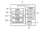
- FIG. 3 schematically illustrates an example of the hardware configuration of the network server according to the embodiment.
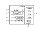
- FIG. 4 schematically illustrates an example of the hardware configuration of the user terminal according to the embodiment.
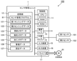
- FIG. 5 schematically illustrates an example of the software configuration of the sensor management unit according to the embodiment.
- FIG. 6 illustrates an example of a processing procedure of matching between a provider of sensing data and a user according to the embodiment.
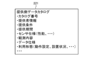
- FIG. 7A schematically illustrates an example of a provider-side data catalog according to the embodiment.
- FIG. 7B schematically illustrates an example of a use-side data catalog according to the embodiment.
- FIG. 8 illustrates an example of the processing procedure of the sensor management unit according to the embodiment.
- FIG. 9 illustrates an example of a process of managing sensing data by the sensor management unit according to the embodiment.
- FIG. 10 schematically illustrates an example of setting data according to the embodiment.
- FIG. 11 schematically illustrates the correspondence between (first) sensing data and various types of metadata according to the embodiment.
- FIG. 12 schematically illustrates an example of management data according to the embodiment.
- the present embodiment an embodiment according to one aspect of the present invention (hereinafter, also referred to as “the present embodiment”) will be described based on the drawings.
- the embodiment described below is merely an illustration of the present invention in all respects. It goes without saying that various improvements and modifications can be made without departing from the scope of the present invention. That is, in the implementation of the present invention, a specific configuration according to the embodiment may be appropriately adopted.
- data appearing in the present embodiment is described in natural language, more specifically, it is specified by a pseudo language, a command, a parameter, a machine language or the like that can be recognized by a computer.
- FIG. 1 schematically illustrates an example of a usage scene of the sensor device 100 according to the present embodiment.
- the sensor device 100 according to the present embodiment is used as a provider that provides sensing data to the user terminal 3 of the user.
- the method of using the sensor device 100 according to the present embodiment is not limited to such an example, and may be appropriately determined according to the embodiment.
- the sensor device 100 includes a first sensor 101 for observing an object, a second sensor 102 for observing a usage pattern of the first sensor 101, and a sensor management unit 1 connected to each sensor (101, 102). Is equipped.
- the first sensor 101 is an example of the “sensor” in the present invention
- the second sensor 102 is an example of the “sub-sensor” in the present invention.
- the type of each sensor (101, 102) may be selected appropriately according to the observation target.
- the sensor management unit 1 is an information processing apparatus configured to manage sensing data (first sensing data 121 described later) obtained by the first sensor 101. Specifically, the sensor management unit 1 acquires sensing data (first sensing data 121 described later) obtained by observing the target by the first sensor 101. Subsequently, the sensor management unit 1 is an attribute of the first sensor 101 at the time when the sensing data is obtained, and indicates an attribute related to the usage pattern of the first sensor 101 that can dynamically change with the passage of time. Target metadata (dynamic metadata 124 described later) is generated.
- the attribute regarding the utilization form of the 1st sensor 101 shown by dynamic metadata is an attribute regarding the operation setting of the 1st sensor 101, an attribute about the installation situation of the 1st sensor 101, etc., for example.
- Information held as dynamic metadata is not limited to a constant value, but relates to an attribute that may change depending on the usage form. That is, the dynamic metadata can be an object to confirm (or track) whether or not the use form of the first sensor 101 has changed in order to determine, for example, the reliability, validity, etc. of the sensing data. Indicates attribute information.
- the sensor management unit 1 appropriately generates such dynamic metadata.
- the use form of the first sensor 101 is monitored by the second sensor 102. Therefore, as one method of generating dynamic metadata, the sensor management unit 1 according to the present embodiment uses sensing data (described later, which is obtained by observing the usage pattern of the first sensor 101 by the second sensor 102 Dynamic metadata is generated based on the second sensing data 122). Then, the sensor management unit 1 manages the generated dynamic metadata in association with the sensing data.
- sensing data associated with dynamic metadata is provided from the sensor device 100 to the user terminal 3 of the user via the network server 2.
- a plurality of sensor devices 100 and a plurality of user terminals 3 are connected to the network server 2 via a network (not shown).
- the type of network may be appropriately selected from, for example, the Internet, a wireless communication network, a mobile communication network, a telephone network, a dedicated network, and the like.
- the network server 2 can match the provision source of the sensing data (sensor device 100) and the use destination (application software etc. executed by the user terminal 3) by a method described later, and can provide the sensing data satisfying the request of the use destination Extract the source of Then, the network server 2 permits the distribution of sensing data between the sensor device 100 in which the matching is established and the user terminal 3. Thereby, in the present embodiment, sensing data is provided from each sensor device 100 to the appropriate user terminal 3.
- the sensor management unit 1 generates, as dynamic metadata, information on the usage mode of the first sensor 101 at the time when sensing data is obtained, and generates the generated dynamic metadata. Manage in association with data. Therefore, the sensor management unit 1 sends, together with the sensing data obtained by the first sensor 101, to each user terminal 3 dynamic metadata indicating information on the usage pattern of the first sensor 101 at the time of obtaining the sensing data. Can be provided.
- each user terminal 3 checks the usage pattern of the first sensor 101 at the time when the sensing data to be used is obtained, by referring to the associated dynamic metadata when using the sensing data. Will be able to That is, in each user terminal 3, processing such as accessing the first sensor 101 to check the usage pattern of the first sensor 101, and inquiring to the sensor management unit 1 managing the first sensor 101 can be omitted. . Therefore, according to the present embodiment, it is possible to reduce the time and effort required to confirm the use form of the first sensor 101 when using the sensing data.
- FIG. 2 schematically illustrates an example of the hardware configuration of the sensor management unit 1 according to the present embodiment.
- the control unit 11, the storage unit 12, the communication interface 13, the external interface 14, the input device 15, the output device 16, and the drive 17 are electrically connected.
- the communication interface and the external interface are described as “communication I / F” and “external I / F”, respectively.
- the control unit 11 includes a hardware processor such as a central processing unit (CPU), a random access memory (RAM), and a read only memory (ROM), and is configured to execute information processing based on a program and various data.
- the storage unit 12 is an example of “memory”, and is configured of, for example, a hard disk drive, a solid state drive, or the like.
- the storage unit 12 includes a sensor management program 81, first sensing data 121, second sensing data 122, static metadata 123, dynamic metadata 124, processing metadata 125, management data 126, and setting. Data 127 and the like are stored.
- the first sensing data 121 is obtained by observing an object with the first sensor 101.
- the second sensing data 122 is obtained by observing the usage pattern of the first sensor 101 by the second sensor 102.
- Each metadata 123 to 125 relates to the first sensor 101, and is associated with the first sensing data 121.
- the management data 126 includes information indicating the correspondence between the first sensing data 121 and the metadata 123 to 125 according to the association.
- the setting data 127 includes information indicating the operation setting of the first sensor 101.
- the sensor management program 81 includes an instruction to cause the sensor management unit 1 to execute information processing (FIG. 8) for managing the first sensing data 121 and the metadata 123 to 125 described later. Details will be described later.
- the communication interface 13 is, for example, a wired LAN (Local Area Network) module, a wireless LAN module, or the like, and is an interface for performing wired or wireless communication via a network.
- the sensor management unit 1 performs data communication with the network server 2 via the communication interface 13.
- the external interface 14 is, for example, a USB (Universal Serial Bus) port, a dedicated port, or the like, and is an interface for connecting to an external device.
- the type and number of external interfaces 14 may be appropriately selected in accordance with the type and number of external devices to be connected.
- the sensor management unit 1 is connected to each sensor (101, 102) via the external interface 14.
- the type of the first sensor 101 may not be particularly limited, and may be appropriately selected according to the embodiment.
- the first sensor 101 may be, for example, an image sensor, an infrared sensor, a sound sensor, an optical sensor, a pressure sensor, an atmospheric pressure sensor, a temperature sensor, or the like.
- the first sensor 101 may be, for example, an environment sensor, a vital sensor, an on-vehicle sensor, a home security sensor, or the like.
- the environmental sensor is a sensor configured to be able to measure or detect environmental information related to atmospheric pressure, temperature, humidity, sound pressure, sound, ultraviolet light, illuminance, rainfall, gas and the like.
- the vital sensor is a sensor configured to be able to measure or detect vital information such as blood pressure, heart rate, electrocardiogram, body temperature, sleep state (microwave), activity amount, blood glucose level and the like.
- An on-vehicle sensor is a sensor mounted in vehicles, such as an image sensor, a laser sensor, and a sleep (microwave) sensor.
- Home security sensors include home sensors such as image sensors, infrared sensors, activity (voice) sensors, gas (CO 2 etc.) sensors, current sensors, smart meters (sensors that measure the amount of power used by home appliances, lighting, etc.)
- the sensor is configured to measure or detect information related to Accordingly, the first sensing data 121 obtained by the first sensor 101 is, for example, image data, numerical data, voice data, language data, and the like.
- the first sensor 101 is appropriately disposed so as to be able to observe the state of the object.
- the type of the second sensor 102 may not be particularly limited as long as the usage mode of the first sensor 101 can be observed, and may be appropriately selected according to the embodiment.
- the second sensor 102 may be, for example, a temperature sensor, a GPS sensor, an acceleration sensor, an atmospheric pressure sensor, a geomagnetic sensor, a gyro sensor, or the like.
- the second sensor 102 is appropriately disposed so as to be able to observe the usage pattern of the first sensor 101.
- a temperature sensor is employed as the second sensor 102
- the second sensor 102 can observe the temperature around the first sensor 101. it can.
- the second sensor 102 is attached to a housing (not shown) of the first sensor 101, whereby the attitude of the first sensor 101 is For example, the direction can be observed.
- one first sensor 101 and one second sensor 102 are connected to the sensor management unit 1.
- the number of each of the first sensor 101 and the second sensor 102 connected to the sensor management unit 1 may not be limited to one, and may be two or more.
- a plurality of first sensors 101 may be connected to the sensor management unit 1.
- a plurality of second sensors 102 may be used.
- the number of sensors (101, 102) connected to the sensor management unit 1 may be appropriately determined according to the embodiment.
- the input device 15 is, for example, a device for performing input such as a mouse and a keyboard.
- the output device 16 is, for example, a device for outputting a display, a speaker or the like. A user who is a provider of sensing data can operate the sensor management unit 1 using the input device 15 and the output device 16.
- the drive 17 is, for example, a CD drive, a DVD drive, or the like, and is a drive device for reading a program stored in the storage medium 91.
- the type of drive 17 may be appropriately selected according to the type of storage medium 91.
- the sensor management program 81 may be stored in the storage medium 91.
- the storage medium 91 stores information such as a program by an electric, magnetic, optical, mechanical or chemical action so that information such as a computer or other device or program recorded on a machine can be read.
- the sensor management unit 1 may obtain the sensor management program 81 from the storage medium 91.
- a disc-type storage medium such as a CD or a DVD is illustrated.
- the type of storage medium 91 is not limited to the disc type, and may be other than the disc type.
- a storage medium other than the disk type for example, a semiconductor memory such as a flash memory can be mentioned.
- the control unit 11 may include a plurality of hardware processors.
- the hardware processor may be configured by a microprocessor, a field-programmable gate array (FPGA), a digital signal processor (DSP), and the like.
- the storage unit 12 may be configured by a RAM and a ROM included in the control unit 11.
- the input device 15 and the output device 16 may be omitted.
- the sensor management unit 1 may be connected to each sensor (101, 102) via the communication interface 13, not the external interface 14. In this case, the external interface 14 may be omitted.
- the sensor management unit 1 is comprised by one information processing apparatus in FIG. 2, you may be comprised by two or more information processing apparatuses.
- the hardware configuration of each information processing device may or may not match.
- the sensor management unit 1 may be a general-purpose desktop PC (Personal Computer), a tablet PC, a smartphone, a mobile phone other than a smartphone, a programmable logic controller (PLC), etc., in addition to an information processing device designed specifically for services. Good.
- PLC programmable logic controller
- FIG. 3 schematically illustrates an example of the hardware configuration of the network server 2 according to the present embodiment.
- the network server 2 is a computer to which the control unit 21, the storage unit 22, and the communication interface 23 are electrically connected.
- the communication interface is described as "communication I / F".
- control unit 21 includes a hardware processor such as a CPU, a RAM, and a ROM, and is configured to execute various information processing based on programs and data.
- the storage unit 22 includes, for example, a hard disk drive, a solid state drive, and the like, and stores the program 82, the providing side data catalog 221, the using side data catalog 222, and the like.
- the program 82 includes an instruction to cause the network server 2 to execute information processing (FIG. 6) for matching a provider and a use destination described later.
- the provider data catalog 221 is prepared for each provider and includes information indicating sensing data (first sensing data 121) that can be provided by the sensor (first sensor 101) of each sensor device 100.
- the use-side data catalog 222 is prepared for each use destination, and includes information indicating sensing data desired by the user.
- the provider data catalog 221 and the user data catalog 222 are used for matching of a provider and a user. Details will be described later.
- the communication interface 23, like the communication interface 13, is an interface for performing communication via a network.
- the communication interface 23 is, for example, a wired LAN module, a wireless LAN module, or the like.
- the network server 2 performs data communication with each sensor device 100 and each user terminal 3 via the communication interface 23.
- control unit 21 may include a plurality of hardware processors.
- the hardware processor may be configured by a microprocessor, an FPGA or the like.
- the storage unit 22 may be configured by a RAM and a ROM included in the control unit 21.
- the network server 2 may further include an input device and an output device as a user interface.
- the network server 2 may be a general-purpose server device, a general-purpose PC, or the like, in addition to an information processing device designed for service only.
- FIG. 4 schematically illustrates an example of the hardware configuration of the user terminal 3 according to the present embodiment.
- the user terminal 3 is a computer in which the control unit 31, the storage unit 32, the communication interface 33, the input device 34, and the output device 35 are electrically connected.
- the communication interface is described as “communication I / F” as in FIGS. 2 and 3.
- the control unit 31 includes a CPU that is a hardware processor, a RAM, a ROM, and the like, similarly to the control units (11, 22), and is configured to execute various information processing based on programs and data.
- the storage unit 32 includes, for example, a hard disk drive, a solid state drive, and the like, and stores the application program 83 and the like.
- the application program 83 includes an instruction to cause the control unit 31 to execute predetermined information processing, and uses sensing data (first sensing data 121) provided from each user terminal 3.
- the type of application program 83 may not be particularly limited, and may be appropriately selected according to the embodiment.
- the communication interface 33 is an interface for performing communication via a network, similarly to the above-described communication interfaces (13, 23).
- the communication interface 33 is, for example, a wired LAN module, a wireless LAN module, or the like.
- the user terminal 3 performs data communication with the network server 2 via the communication interface 33.
- the input device 34 is, for example, a device for performing an input such as a mouse and a keyboard as the input device 15 described above.
- the output device 35 is, for example, a device for outputting a display, a speaker, and the like, as in the case of the output device 16.
- the user of the sensing data can operate the user terminal 3 using the input device 34 and the output device 35.
- control unit 31 may include a plurality of hardware processors.
- the hardware processor may be configured by a microprocessor, an FPGA, or the like.
- the storage unit 32 may be configured by a RAM and a ROM included in the control unit 31.
- the user terminal 3 may be a general-purpose desktop PC, a tablet PC, a smartphone, a mobile phone other than a smartphone, or the like, in addition to an information processing apparatus designed specifically for service.
- FIG. 5 schematically illustrates an example of the software configuration of the sensor management unit 1 according to the present embodiment.
- the control unit 11 of the sensor management unit 1 deploys the sensor management program 81 stored in the storage unit 12 in the RAM. Then, the control unit 11 causes the CPU to interpret the sensor management program 81 expanded in the RAM, and executes information processing based on the interpretation while controlling each component.
- the sensor management unit 1 includes, as software modules, a sensing data acquisition unit 111, a metadata generation unit 112, an identification code generation unit 113, a metadata management unit 114,
- the configuration is configured as a computer including the first communication unit 115, the second communication unit 116, and the catalog change unit 117.
- the sensing data acquisition unit 111 acquires the first sensing data 121 obtained by observing the target by the first sensor 101.
- the metadata generation unit 112 is an attribute of the first sensor 101 at the time when the first sensing data 121 is obtained, and indicates an attribute related to the usage pattern of the first sensor 101 that can dynamically change with the passage of time. Dynamic metadata 124 is generated. In the present embodiment, the metadata generation unit 112 generates the dynamic metadata 124 based on the second sensing data 122 and the like obtained by observing the usage pattern of the first sensor 101 by the second sensor 102. .
- the metadata generation unit 112 generates static metadata 123 and processing metadata 125 in addition to the dynamic metadata 124.
- the static metadata 123 indicates an attribute related to the specification of the first sensor 101 that does not change with time. That is, the information held as the static metadata 123 basically relates to an attribute whose value is always constant and which is not likely to change depending on the usage form.
- the processing metadata 125 relates to the feature amount of the acquired first sensing data 121, and is generated by analyzing the acquired first sensing data 121.
- the identification code generation unit 113 includes a first identification code (sensing data ID described later) for identifying the first sensing data 121, and a second identification code (static described later for identifying each of the metadata 123 to 125). Metadata ID, Dynamic Metadata ID, and Processed Metadata ID) are generated.
- the metadata management unit 114 manages the generated metadata 123 to 125 in association with the first sensing data 121.
- the first communication unit 115 transmits the first sensing data 121 to an external device such as each user terminal 3 or the like.
- the second communication unit 116 transmits the metadata 123 to 125 to the external device.
- the catalog changing unit 117 changes the contents of the provider data catalog 221 stored in the network server 2 in accordance with the change of the usage pattern of the first sensor 101.
- each software module of the sensor management unit 1 will be described in detail in an operation example described later.
- an example in which each software module of the sensor management unit 1 is realized by a general-purpose CPU is described.
- the method of implementing each software module may not be limited to such an example.
- Some or all of the software modules may be implemented by one or more dedicated processors. Further, regarding the software configuration of the sensor management unit 1, omission, replacement, and addition of software modules may be appropriately performed according to the embodiment.
- FIG. 6 shows an example of a processing procedure of matching by the network server 2 according to the present embodiment.
- the processing procedure of the matching described below is only an example, and each processing may be changed as much as possible.
- steps may be omitted, replaced, or added as appropriate, according to the embodiment.
- Step S11 and S12 First, in step S ⁇ b> 11, the control unit 21 of the network server 2 acquires a providing-side data catalog 221 indicating sensing data that can be provided by each sensor device 100. In the next step S12, the control unit 21 acquires the use-side data catalog 222 indicating the sensing data desired by the user.
- FIG. 7A schematically illustrates an example of the provider-side data catalog 221 according to the present embodiment.
- the provider-side data catalog 221 according to the present embodiment includes information such as catalog number, provider information, provision condition, provision period, sensor specification, observation content, data specification, usage form and the like.
- the control unit 21 may appropriately generate the provider data catalog 221 by acquiring various information registered in the provider data catalog 221.
- the catalog number is a number for identifying the provider data catalog 221.
- the control unit 21 may appropriately generate an arbitrary number not used for the other providing side data catalog 221, and set the generated number as the catalog number.
- provider information is information for specifying the provider of sensing data, For example, a provider's name (personal name or organization name), a provider's contact point etc. may be included.
- the information on the provision conditions defines the conditions under which the provision of sensing data is permitted.
- the provision conditions include, for example, usage of sensing data (commercial / non-commercial / no restriction), scope of provision (providing to third party / not permitted), access right (replication impossible / replication possible / modification possible / processable) Conditions such as presence or absence of personal information, presence or absence of anonymous processing information, and payment types of expenses for use of sensing data may be included.
- Information on the provision period defines a period for which provision of sensing data is permitted (for example, the start date and end date of the provision).
- the control unit 21 receives the input or designation from the provider via each sensor device 100 or other information processing apparatus when generating the provider-side data catalog 221, thereby providing provider information, provision conditions, and provision. You may acquire each information of a period.
- the information on the sensor specification indicates an attribute on the specification of the first sensor 101, and may include, for example, information on the performance of the first sensor 101, device information, information on an initial installation condition, and the like.
- the information related to the performance of the first sensor 101 may include, for example, information such as the sensitivity limit of the first sensor 101, the dynamic range, the settable range of the spatial resolution, and the settable range of the sampling frequency.
- the device information of the first sensor 101 may include, for example, information such as the name of the first sensor 101, the description of the first sensor 101, and the like.
- the information on the initial installation condition of the first sensor 101 may include, for example, information such as a proper noun of the installation place of the first sensor 101.
- the information about the observation content indicates the attribute of the observation performed using the first sensor 101, and, for example, the name of the observation (for example, environmental observation), the explanation about the observation, and the name of the target for observation (for example, A establishment) ,
- the description about the observation object, the name of the observation index (for example, temperature, humidity, etc.), the explanation about the observation index, etc. may be included.
- the data specification information indicates an attribute related to the specification of the first sensing data 121 obtained by the first sensor 101.
- the name of the observed value (temperature value, maximum power consumption value, etc.) indicated by the first sensing data 121, It may include information such as the explanation of the observation value and the unit of the observation value.
- the control unit 21 When the control unit 21 generates the provider-side data catalog 221, the sensor specification, the observation content, and the data specification are obtained from the static metadata 123 associated with the first sensor 101 or the first sensing data 121 of each sensor device 100. Of each information may be acquired.
- the information on the usage mode indicates an attribute of the first sensor 101 that may change according to the usage mode, and may include, for example, information on operation setting of the first sensor 101 and information on the installation status of the first sensor 101 .
- the information on the operation setting of the first sensor 101 may include, for example, information such as a set value of the measurement range of the first sensor 101, a set value of resolution of the measurement range, and a set value of the sampling frequency.
- the information on the installation state of the first sensor 101 may include, for example, information such as the installation angle of the first sensor 101, the temperature around the first sensor 101, and the distance between the first sensor 101 and the observation target. Good.
- the control unit 21 may obtain information on the usage form from the dynamic metadata 124 associated with each sensor device 100 or the first sensing data 121.
- FIG. 7B schematically illustrates an example of the use-side data catalog 222 according to the present embodiment.
- the use-side data catalog 222 according to the present embodiment includes information such as catalog number, user information, collection condition, use period, sensor specification, observation content, data specification, use form and the like.
- the control unit 21 receives input or designation from the user via each user terminal 3 or other information processing apparatus, and acquires various information to be registered in the use-side data catalog 222.
- the data catalog 222 may be generated as appropriate.
- the catalog number is the same as the catalog number of the provider data catalog 221.
- each information of user information, collection condition, use period, sensor specification, observation content, data specification, and use form is the provider information of the above-mentioned provider data catalog 221, provision condition, provision period, sensor specification, observation It corresponds to each information of content, data specification, and usage form.
- the user information is information for identifying the user of the sensing data.
- the information on receipt conditions defines conditions for accepting provision of sensing data.
- the information on the usage period defines a period (for example, start date and time and usage end date and time of use) for which provision of sensing data is desired or desired to be provided.
- the information on the sensor specification indicates an attribute on the specification of the sensor for which it is desired to provide sensing data.
- the information on the content of observation indicates the attribute of the observation for which it is desired to provide sensing data.
- the data specification information indicates an attribute related to the specification of sensing data desired to be provided.
- the information on the use form indicates an attribute that may change according to the use form of the sensor for which provision of sensing data is desired.
- each information of user information, collection condition, usage period, sensor specification, observation content, data specification, and usage form are the provider information of the above-mentioned provider data catalog 221, provision condition, provision period, sensor It may be the same as the information of the specification, the observation content, the data specification, and the usage form.
- the generation of the provider data catalog 221 and the user data catalog 222 may not be performed by the network server 2.
- the provider data catalog 221 may be generated by each sensor device 100 or another information processor of the provider.
- the use-side data catalog 222 may be generated by each user terminal 3 or another information processing apparatus of the user.
- the control unit 21 may acquire the provider data catalog 221 from each sensor device 100 or another information processor of the provider via the network.
- the control unit 21 may acquire the use-side data catalog 222 from each user terminal 3 or another information processing apparatus of the user via the network.
- Steps S13 and S14 In the next step S13, the control unit 21 matches the provision source with the use destination by collating each item of the provision side data catalog 221 with each item of the use side data catalog 222. In the next step S14, based on the result of the matching, the sensor device 100 (first sensor 101) capable of providing sensing data (first sensing data 121) satisfying the user's request is extracted.
- the control unit 21 provides the provision condition of the provider data catalog 221, the provision period, the sensor specification, the observation content, the data specification, the collection condition of each item of the usage form and the usage data catalog 222, and uses Each item of a period, a sensor specification, an observation content, a data specification, and a utilization form is collated, and it is determined whether each item is suitable. As a result of the determination, when all or part of the items match, the control unit 21 senses the sensor device 100 corresponding to the provider data catalog 221 to satisfy the user request corresponding to the user data catalog 222. Extract data as available.
- control unit 21 determines that the sensor device 100 corresponding to the provider-side data catalog 221 can not provide sensing data satisfying the request of the user corresponding to the user-side data catalog 222 Do.
- the method of matching may not be limited to such an example, and may be appropriately determined according to the embodiment.
- Step S15 the control unit 21 permits the distribution of the sensing data (first sensing data 121) from the extracted sensor device 100 to the target user terminal 3.
- the control unit 21 transmits, to the extracted sensor device 100, a data flow permission instruction indicating that transmission of sensing data to the target user terminal 3 is permitted.
- each sensor device 100 transmits the first sensing data 121 obtained by observing the target with the first sensor 101 to the target user terminal 3 specified by the data flow permission command.
- the control unit 21 ends the matching process according to the present operation example.
- FIG. 8 illustrates an example of a processing procedure for managing the first sensing data 121 by the sensor management unit 1 according to the present embodiment.
- FIG. 9 schematically illustrates an example of a management process of the first sensing data 121 by the sensor management unit 1 according to the present embodiment.
- the processing procedure described below is an example of the “sensor management method” in the present invention. However, the processing procedure described below is merely an example, and each processing may be changed as much as possible. In addition, according to the embodiment, steps may be omitted, replaced, or added as appropriate, according to the embodiment.
- Step S101 First, in step S101, the control unit 11 of the sensor management unit 1 operates as the sensing data acquisition unit 111, and acquires the first sensing data 121 obtained by observing the target by the first sensor 101.
- the sensor management unit 1 holds setting data 127 indicating the operation setting of the first sensor 101. Therefore, the control unit 11 refers to the setting data 127 to specify the operation setting of the first sensor 101.
- FIG. 10 schematically illustrates an example of the setting data 127 according to the present embodiment.
- the setting data 127 includes, for example, information such as a setting value of the measurement range, a setting value of the resolution of the measurement range, and a setting value of the sampling frequency as information indicating the operation setting of the first sensor 101.
- the control unit 11 controls the operation of the first sensor 101 based on these pieces of information.
- control unit 11 controls the operation of the first sensor 101 based on the setting value of the measurement range indicated by the setting data 127 and the setting value of the resolution. Then, the control unit 11 sets a setting value indicated by the setting data 127 as a sampling frequency, and performs sampling processing of a signal output from the first sensor 101. Thereby, the control unit 11 can acquire the first sensing data 121.
- the method of acquiring the first sensing data 121 may not be limited to such an example, and may be appropriately determined according to the embodiment.
- control and sampling processing of the first sensor 101 may be performed by another information processing apparatus.
- the control unit 11 may acquire the first sensing data 121 from the other information processing apparatus.
- the control unit 11 proceeds to the next step S102.
- the first sensing data 121 may be configured to be time-series data having a certain time width, or may be configured to indicate an observation result of a temporary point.
- the configuration of the first sensing data 121 may not be particularly limited, and may be appropriately determined according to the embodiment.
- Step S102 In the next step S102, the control unit 11 operates as the identification code generation unit 113, and generates a sensing data ID for identifying the first sensing data 121 acquired in step S101.
- the sensing data ID is an example of the “first identification code”.
- the configuration of the sensing data ID may not be particularly limited, and may be appropriately determined according to the embodiment.
- the control unit 11 senses an arbitrary character string different from the character string of the sensing data ID which is not attached to the other first sensing data 121, that is, paired with the other first sensing data 121. You may generate suitably as data ID.
- the control unit 11 pairs the generated sensing data ID with the first sensing data 121 acquired in step S101. Thus, when the generation of the sensing data ID is completed, the control unit 11 proceeds to the next step S103.
- Step S103 In the next step S103, the control unit 11 operates as the metadata generation unit 112, and generates static metadata 123, dynamic metadata 124, and processing metadata 125. After generating the metadata 123 to 125, the control unit 11 advances the process to the next step S104.
- the static metadata 123 is configured to indicate an attribute related to the specification of the first sensor 101, which does not change as time passes, as described above. As long as it is configured as such, the contents of the static metadata 123 may be appropriately determined according to the embodiment.
- the static metadata 123 may include, for example, an attribute related to the performance of the first sensor 101, an attribute related to device information of the first sensor 101, an attribute related to an initial installation condition of the first sensor 101, and the like.
- the control unit 11 obtains information corresponding to each item from the first information sensor 101 or another information processing apparatus that holds information on the specification of the first sensor 101, and generates static metadata 123 based on the obtained information. You may
- Dynamic metadata Dynamic metadata 124 is an attribute of the first sensor 101 at the time when the first sensing data 121 is obtained, as described above, and can be dynamically changed with the passage of time. It is configured to indicate an attribute related to the usage pattern of the first sensor 101. As long as it is configured as such, the contents of the dynamic metadata 124 may be appropriately determined according to the embodiment.
- the attribute relating to the usage form of the first sensor 101 indicated by the dynamic metadata 124 may include, for example, an attribute relating to the operation setting of the first sensor 101, an attribute relating to the installation state of the first sensor 101, and the like.
- the attributes related to the operation setting of the first sensor 101 are, for example, a set value of the measurement range, a set value of the resolution of the measurement range, a set value of the sampling frequency, and the like.
- information on the operation setting of the first sensor 101 is stored in the storage unit 12 as setting data 127. Therefore, the control unit 11 may acquire the information related to the operation setting of the first sensor 101 by referring to the setting data 127, and may generate the dynamic metadata 124 based on the acquired information.
- the attribute regarding the installation condition of the first sensor 101 is, for example, an installation angle of the first sensor 101, a temperature around the first sensor 101, a distance between the first sensor 101 and an observation target, and the like.
- the use form of the first sensor 101 is monitored by the second sensor 102 connected to the sensor management unit 1. Therefore, the control unit 11 may generate the dynamic metadata 124 based on the second sensing data 122 obtained by observing the usage pattern of the first sensor 101 by the second sensor 102.
- the second sensing data 122 obtained by the second sensor 102 is the temperature around the first sensor 101 Show. Therefore, even if the control unit 11 acquires the second sensing data 122 and generates data indicating the temperature around the first sensor 101 as the dynamic metadata 124 based on the acquired second sensing data 122. Good.
- the control unit 11 may acquire the second sensing data 122 and generate data indicating the installation angle of the first sensor 101 as the dynamic metadata 124 based on the acquired second sensing data 122. .
- the configuration of the dynamic metadata 124 may not be limited to such an example, and may be appropriately determined according to the embodiment. For example, at least one of the information on the attribute related to the operation setting of the first sensor 101 and the information on the attribute related to the installation status may be omitted. Also, the dynamic metadata 124 may include information on attributes regarding the usage form of the first sensor 101 other than the information on the attribute regarding the operation setting of the first sensor 101 and the information about the attribute regarding the installation status.
- control unit 11 may generate the dynamic metadata 124 regardless of the setting data 127 and the second sensing data 122.
- the control unit 11 may generate the dynamic metadata 124 based on the first sensing data 121.
- the control unit 11 analyzes the first sensing data 121 to specify the distance between the first sensor 101 and the observation target, and the specified distance May be generated as dynamic metadata 124.
- the dynamic metadata 124 is configured to indicate an attribute related to the usage pattern of the first sensor 101 at the time when the first sensing data 121 is obtained. Therefore, it is preferable that the point in time of the usage pattern of the first sensor 101 indicated by the dynamic metadata 124 coincide with the point in time when the first sensing data 121 is obtained. However, this “when the first sensing data 121 is obtained” may not be exact.
- the time of the usage pattern of the first sensor 101 indicated by the dynamic metadata 124 and the time of obtaining the first sensing data 121 may not completely coincide, and the dynamic metadata 124 They may be offset from each other as long as they do not have a fatal impact on usage.
- the point of time of usage of the first sensor 101 indicated by the dynamic metadata 124 and the point of time when the first sensing data 121 are obtained deviate from each other to such an extent that the utilization of the dynamic metadata 124 is not adversely affected. Is also included in the "point when the first sensing data 121 is obtained".
- control unit 11 may acquire the setting data 127 and the second sensing data 122 used to generate the dynamic metadata 124 at the same timing as the first sensing data 121, or the first sensing data 121. And may be acquired at different timings.
- the method of acquiring the second sensing data 122 may be the same as the method of acquiring the first sensing data 121 in step S101.
- the processed metadata 125 is configured to indicate the feature value of the first sensing data 121 acquired in step S101 as described above. As long as it is configured as such, the content of the processing metadata 125 may be appropriately determined according to the embodiment.
- the control unit 11 can generate processing metadata 125 by executing a predetermined analysis process on the first sensing data 121 acquired in step S101.
- the type of predetermined analysis processing when generating the processing metadata 125 may not be particularly limited, and may be appropriately selected according to the embodiment.
- the predetermined analysis processing may be, for example, labeling processing, arithmetic processing for deriving a variation, arithmetic processing for deriving a vector value, conversion processing, cleansing processing, filtering processing, and the like.
- the conversion process is an arithmetic process for aligning units, scales, and the like. Cleansing processing is arithmetic processing for removing data other than the true value of sensing data.
- the filtering process is an arithmetic process for applying a filter such as an LPF, an HPF, or a BPF to sensing data.
- the type of the feature amount obtained as the processing metadata 125 by the analysis processing is not particularly limited as long as it indicates the feature of the first sensing data 121 acquired in step S101, and according to the embodiment May be selected appropriately.
- the feature amount obtained as the processing metadata 125 may be, for example, a label, a change amount, a vector value, an outlier, or the like.
- the contents of the dynamic metadata 124 and the processing metadata 125 depend on the timing and content of acquiring the first sensing data 121. Therefore, the control unit 11 newly generates the dynamic metadata 124 and the processing metadata 125 with respect to the acquired first sensing data 121 each time the processing of steps S101 to S103 is repeated.
- the content of the static metadata 123 does not depend on the first sensing data 121. Therefore, after creating the static metadata 123 once, the control unit 11 does not have to newly create the static metadata 123 for the same first sensor 101. That is, the control unit 11 may generate the static metadata 123 only when the present step S103 is executed for the first time.
- the timing of generating the static metadata 123 may be different from the timing of executing the present step S103.
- the control unit 11 connects, for example, the first sensor 101 to the sensor management unit 1 before executing step S101, and sets the static meta to the sensor management unit 1 at the time of initial setting for registering the first sensor 101. Data 123 may be generated.
- Step S104 In the next step S104, the control unit 11 operates as the identification code generation unit 113, and is used to identify each of the static metadata 123, the dynamic metadata 124, and the processing metadata 125 generated in step S103.
- the target metadata ID, the dynamic metadata ID, and the processing metadata ID are generated.
- Each metadata ID is an example of the “second identification code”.
- each metadata ID may not be particularly limited, and may be appropriately determined according to the embodiment.
- the control unit 11 can generate each metadata ID in the same manner as the sensing data ID.
- the control unit 11 pairs the generated static metadata ID with the static metadata 123 generated in step S103.
- the control unit 11 pairs the generated dynamic metadata ID with the dynamic metadata 124 generated in step S103.
- the control unit 11 pairs the generated processing metadata ID with the processing metadata 125 generated in step S103.
- the control unit 11 advances the process to the next step S105.
- the static metadata 123 may be generated before performing step S101. Therefore, the timing at which the static metadata ID is generated may be different from the timing at which the present step S104 is performed.
- the control unit 11 connects, for example, the first sensor 101 to the sensor management unit 1 before executing step S101, and sets the static meta to the sensor management unit 1 at the time of initial setting for registering the first sensor 101.
- a data ID may be generated.
- Step S105 In the next step S105, the control unit 11 operates as the metadata management unit 114, and associates the metadata 123 to 125 generated in step S103 with the first sensing data 121 acquired in step S101.
- a sensing data ID is generated for the first sensing data 121
- each metadata ID is generated for each of the metadata 123 to 125. Therefore, the control unit 11 associates each metadata 123 to 125 with the first sensing data 121 using the sensing data ID and each metadata ID.
- the control unit 11 updates the management data 126 by adding the result of the association to the management data 126.
- the control unit 11 manages the correspondence between each of the metadata 123 to 125 and the first sensing data 121.
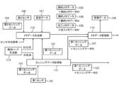
- FIG. 11 schematically illustrates the correspondence between the first sensing data 121 and each of the metadata 123 to 125.
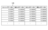
- FIG. 12 schematically illustrates an example of the management data 126 according to the present embodiment. 11 and 12, the dynamic metadata 124 and the processing metadata 125 are newly generated each time the first sensing data 121 is acquired, whereas the static metadata 123 is one time. An example will not be newly generated after being generated.
- the first sensing data 121 such as "D0000” is acquired, and accordingly, the sensing data ID such as "ID_D0000” is each first sensing data 121. It is tied to.
- dynamic metadata 124 such as “DM0000” and processed metadata 125 such as "PM0000” are generated for each first sensing data 121. Accordingly, dynamic metadata IDs such as “ID_DM0000” are linked to each dynamic metadata 124, and process metadata IDs such as “ID_PM0000” are linked to each process metadata 125.
- static metadata 123 “SM 0000” is generated, and in response to this, static metadata ID “ID_SM 0000” is linked to the static metadata 123.
- the control unit 11 associates the dynamic metadata 124 and the processing metadata 125 with the corresponding first sensing data 121.
- the dynamic metadata 124 “DM 000 n” and the processing metadata 125 “PM 000 n” are associated with the first sensing data 121 “D 000 n” (n is 0 to 5).
- the control unit 11 commonly associates the static metadata 123 with each first sensing data 121.
- the static metadata “SM 0000” is associated with each first sensing data 121 “D 000 n” (n is 0 to 5).
- the control unit 11 stores, as management data 126, information indicating the correspondence by the association.
- each record (row data) of the management data 126 indicates the correspondence by each association.
- each record of the management data 126 has a field for storing each of the sensing data ID, the dynamic metadata ID, the processing metadata ID, and the static metadata ID.
- the control unit 11 can add the result of the association to the management data 126 by storing the associated first sensing data 121 and the IDs of the metadata 123 to 125 in the fields of the new record.
- the management data 126 is expressed in a table format.
- the data format of the management data 126 may not be limited to such a table format, and may be appropriately selected according to the embodiment.
- control unit 11 can associate each of the metadata 123 to 125 with the first sensing data 121. Further, the correspondence relationship by the association is managed by the management data 126. After these processes are completed, the control unit 11 advances the process to the next step S106.
- Step S106 In the next step S106, the control unit 11 stores the first sensing data 121 and the metadata 123 to 125 in the storage unit 12. After the storage process is completed, the control unit 11 advances the process to the next step S107.
- the control unit 11 may store the first sensing data 121 in the storage unit 12 at an arbitrary timing.
- the control unit 11 may store the metadata 123 to 125 in the storage unit 12 at an arbitrary timing after generating the metadata 123 to 125.
- Step S107 the control unit 11 operates as the first communication unit 115, and transmits the first sensing data 121 acquired in step S101 to the user terminal 3 permitted to be distributed by the network server 2. At this time, the control unit 11 may transmit the sensing data ID to the user terminal 3 together with the first sensing data 121.
- control unit 11 operates as the second communication unit 116, and transmits the metadata 123 to 125 generated in step S103 to the user terminal 3. At this time, similarly to the first sensing data 121, the control unit 11 may transmit each metadata ID to the user terminal 3 together with each metadata 123 to 125.
- the first communication unit 115 communicates with the external device (user terminal 3) through the first communication port in order to reduce the load for data transmission, while the second communication unit 116 does not communicate with the first device.
- the second communication port different from the communication port may communicate with the external device. That is, while the control unit 11 transmits the first sensing data 121 to the user terminal 3 through the first communication port, the control unit 11 transmits the metadata 123 to 125 to the user terminal 3 through the second communication port. It is also good.
- the communication port is an endpoint for data communication.
- the control unit 11 transmits the first sensing data 121 and the metadata 123 to 125 at different communication ports by specifying different port numbers using TCP (Transmission Control Protocol) or UDP (User Datagram Protocol). Can.
- TCP Transmission Control Protocol
- UDP User Datagram Protocol
- the ports for transmitting the first sensing data 121 and the metadata 123 to 125 may not be limited to such an example, and may be the same.
- control unit 11 may transmit the first sensing data 121 and each of the metadata 123 to 125 to the target user terminal 3 through the network server 2, or the target without the network server 2. It may be transmitted directly to the user terminal 3 of When transmitting via the network server 2, the network server 2 transfers the first sensing data 121 and the metadata 123 to 125 received from each sensor management unit 1 to the target user terminal 3.
- the timing of transmitting the first sensing data 121 and the timing of transmitting each of the metadata 123 to 125 may be simultaneous or may be different from each other. Furthermore, the timings of transmitting the metadata 123 to 125 may be simultaneous or may be different from each other. The timings of transmitting the first sensing data 121 and the metadata 123 to 125 may be appropriately determined according to the embodiment.
- the control unit 11 ends the series of processes according to the present operation example.
- the application program 83 can use the first sensing data 121 and the metadata 123 to 125.
- the control unit 11 may execute the process from step S101 again. That is, the control unit 11 may repeatedly execute the series of processes of steps S101 to S107 until the observation of the target by the first sensor 101 is completed.
- the processing procedure for sensor management according to the present operation example may be changed as much as possible.
- the series of processes of steps S101 to S106 and the process of step S107 may be performed at different timings.
- the process of step S102 may be performed later than the process of step S103.
- the control unit 11 may execute the process of association in step S105.
- control unit 11 operates as the catalog changing unit 117, and A command may be sent to the network server 2 to change the content of the usage pattern to conform to the content of the generated dynamic metadata 124.
- a command may be sent to the network server 2 to change the content of the usage pattern to conform to the content of the generated dynamic metadata 124.
- the method of updating the contents of the usage form of the provider-side data catalog 221 may not be limited to such an example.
- the network server 2 does not wait for such an instruction and receives it from each sensor management unit 1. Based on the contents of the dynamic metadata 124, the information on the usage pattern of the target provider data catalog 221 may be changed.
- control unit 11 may receive a change in the operation setting of the first sensor 101 from the user via the network server 2, each user terminal 3, or another information processing apparatus.
- the information on the use form of the use-side data catalog 222 may be used to designate the change content of the operation setting of the first sensor 101. That is, the control unit 11 may receive, as a command instructing change of the operation setting of the first sensor 101, information related to the use form of the use-side data catalog 222.
- control unit 11 may correct the content of the setting data 127 to the content specified by the user, and change the operation setting of the first sensor 101 when acquiring the first sensing data 121.
- the operation setting of the first sensor 101 can be changed according to the request of each user.
- step S107 information on the usage pattern of the first sensor 101 at the time when the first sensing data 121 is obtained is generated as the dynamic metadata 124 by the processing of steps S101 to S105.
- the target metadata 124 is managed in association with the first sensing data 121. Therefore, in step S107, together with the first sensing data 121 obtained by the first sensor 101, the dynamic metadata 124 indicating information on the usage pattern of the first sensor 101 at the time when the first sensing data 121 is obtained is It can be provided to each user terminal 3.
- each user terminal 3 refers to the associated dynamic metadata 124 to obtain the first sensor at the time when the first sensing data 121 to be used is obtained.
- the usage form of 101 can be confirmed. That is, in each user terminal 3, processing such as accessing the first sensor 101 to check the usage pattern of the first sensor 101, and inquiring to the sensor management unit 1 managing the first sensor 101 can be omitted. . Therefore, according to the present embodiment, when using the first sensing data 121, it is possible to reduce the time and effort required to confirm the usage pattern of the first sensor 101.
- Each user terminal 3 can use the dynamic metadata 124 to determine the reliability, validity, and the like of the first sensing data 121. Furthermore, each user terminal 3 can track whether or not the usage pattern of the target first sensor 101 has been changed by continuously acquiring the dynamic metadata 124.
- the static metadata 123 is generated, and the generated static metadata 123 is associated with the first sensing data 121.
- each user terminal 3 can search the first sensing data 121 based on the specification of the first sensor 101 by acquiring the static metadata 123. Therefore, according to the present embodiment, the searchability of the first sensing data 121 can be enhanced by providing the static metadata 123.
- processing metadata 125 is generated, and the generated processing metadata 125 is associated with the first sensing data 121.
- each user terminal 3 refers to the associated processing metadata 125 when using the first sensing data 121, so that the first sensing data 121 can be obtained without performing predetermined analysis processing. Feature quantities can be acquired. Therefore, according to the present embodiment, in each user terminal 3, the analysis processing for deriving the feature value of the first sensing data 121 can be omitted, and the processing load for using the first sensing data 121 can be reduced. be able to.
- step S103 dynamic metadata 124 can be appropriately generated based on the second sensing data 122 obtained by the second sensor 102.
- the sensor device 100 (sensor management unit 1) is connected to the network server 2 via the network, and the first sensing data 121 is sent to the user terminal 3 of each user according to the result of matching by the network server 2.
- the method of providing the first sensing data 121 may not be limited to such an example, and may be appropriately determined according to the embodiment.
- the first sensing data 121 and the metadata 123 to 125 may be stored in a storage medium, and may be provided to an external device via the storage medium.
- at least one of the first communication unit 115 and the second communication unit 116 may be omitted.
- the sensor management unit 1 may not include the first communication unit 115 and the second communication unit 116, but may include one communication unit that transmits the first sensing data 121 and the metadata 123 to 125.
- step S103 of the above embodiment the control unit 11 of the sensor management unit 1 can generate the dynamic metadata 124 based on the second sensing data 122 obtained by the second sensor 102.
- the method of generating the dynamic metadata 124 may not be limited to such an example, and the control unit 11 may generate the dynamic metadata 124 not based on the second sensing data 122. . In this case, the second sensor 102 may be omitted.
- static metadata 123 and processing metadata 125 are generated and associated with the first sensing data 121.
- the static metadata 123 and the processing metadata 125 may not necessarily be generated. At least one of the static metadata 123 and the processing metadata 125 may be omitted.
- the sensor management unit 1 in order to change the contents of the provider data catalog 221 based on the dynamic metadata 124, the sensor management unit 1 includes the catalog change unit 117 as a software module. However, the catalog changing unit 117 may be omitted.
- the sensing data ID is linked to the first sensing data 121
- each metadata ID is linked to the metadata 123 to 125.
- the sensing data IDs and the metadata IDs are used to associate the first sensing data 121 with the metadata 123 to 125, respectively.
- the method of associating the first sensing data 121 with each of the metadata 123 to 125 may not be limited to such an example, and may be appropriately determined according to the embodiment.
- the first sensing data 121 may be associated with each of the metadata 123 to 125 regardless of the sensing data ID and each metadata ID. In this case, the sensing data ID and each metadata ID may be omitted.
- the sensor device 100 (the sensor management unit 1) transmits the second sensing data 122 to the external device such as the user terminal 3 together with the first sensing data 121 or in place of the first sensing data 121. May be provided.
- the sensor management unit 1 may generate the metadata 123 to 125 for the second sensing data 122, and manage the generated metadata 123 to 125 in association with the second sensing data 122. That is, the second sensing data 122 may be treated as the "sensing data" of the present invention together with or instead of the first sensing data 121.
- the static metadata 123 may change according to the use form It relates to non-sex attributes.
- the changing / non-changing period may be limited to the period for providing sensing data. That is, as a result of the matching by the network server 2, the attribute of the first sensor 101 that may change within the period in which the first sensing data 121 is provided from the sensor management unit 1 to the target user terminal 3 is a dynamic meta It is treated as an object of the data 124, and the attribute of the first sensor 101 which is not possible may be treated as an object of the static metadata 123. In this case, the attribute indicated by the static metadata 123 may change (change) outside the period of providing the first sensing data 121.
- ... sensor management unit 11: control unit, 12: storage unit, 13: communication interface, 14: external interface, 15: input device, 16: output device, 17 ... drive, 100 ... sensor device, 101 ... first sensor (sensor), 102 ... second sensor (sub sensor), 111 ... sensing data acquisition unit, 112 ... metadata generation unit, 113: identification code generation unit 114: metadata management unit 115: first communication unit 116: second communication unit 117 ... catalog change unit, 121 ... first sensing data, 122 ... second sensing data, 123 ... static metadata, 124 ... dynamic metadata, 125 ... processing metadata, 126 ... management data, 127 ... setting data, 2 ...
- Network server 21: control unit, 22: storage unit, 23: communication interface, 221 ... provider-side data catalog, 222 ... user side data catalog, 3 ...
- User terminal 31: control unit, 32: storage unit, 33: communication interface, 34 ... input device, 35 ... output device, 81: Sensor management program, 82 ... program, 83 ... program, 91: Storage medium
Landscapes
- Physics & Mathematics (AREA)
- General Physics & Mathematics (AREA)
- Engineering & Computer Science (AREA)
- Computer Networks & Wireless Communication (AREA)
- Signal Processing (AREA)
- Technology Law (AREA)
- Health & Medical Sciences (AREA)
- Computing Systems (AREA)
- General Health & Medical Sciences (AREA)
- Medical Informatics (AREA)
- Arrangements For Transmission Of Measured Signals (AREA)
Abstract
Selon un aspect de l'invention, une unité de gestion de capteur comprend : une unité d'acquisition de données de détection pour acquérir des données de détection par observation d'un sujet au moyen d'un capteur; une unité de génération de métadonnées pour générer des métadonnées dynamiques exprimant un attribut du capteur lorsque les données de détection obtenues se rapportent à un état d'utilisation du capteur qui peut changer de façon dynamique dans le temps; et une unité de gestion de métadonnées pour gérer les métadonnées dynamiques générées en association avec les données de détection.
Priority Applications (3)
| Application Number | Priority Date | Filing Date | Title |
|---|---|---|---|
| EP18842902.1A EP3667251A4 (fr) | 2017-08-09 | 2018-07-17 | Unité de gestion de capteur, dispositif capteur, procédé de gestion de capteur, et programme de gestion de capteur |
| US16/632,898 US20200166388A1 (en) | 2017-08-09 | 2018-07-17 | Sensor management unit, sensor device, sensor management method, and sensor management program |
| CN201880049777.3A CN110998245A (zh) | 2017-08-09 | 2018-07-17 | 传感器管理单元、传感器装置、传感器管理方法以及传感器管理程序 |
Applications Claiming Priority (4)
| Application Number | Priority Date | Filing Date | Title |
|---|---|---|---|
| JP2017153898 | 2017-08-09 | ||
| JP2017-153898 | 2017-08-09 | ||
| JP2017230051A JP6451820B1 (ja) | 2017-08-09 | 2017-11-30 | センサ管理ユニット、センサ装置、センサ管理方法及びセンサ管理プログラム |
| JP2017-230051 | 2017-11-30 |
Publications (1)
| Publication Number | Publication Date |
|---|---|
| WO2019031162A1 true WO2019031162A1 (fr) | 2019-02-14 |
Family
ID=65020436
Family Applications (1)
| Application Number | Title | Priority Date | Filing Date |
|---|---|---|---|
| PCT/JP2018/026630 WO2019031162A1 (fr) | 2017-08-09 | 2018-07-17 | Unité de gestion de capteur, dispositif capteur, procédé de gestion de capteur, et programme de gestion de capteur |
Country Status (5)
| Country | Link |
|---|---|
| US (1) | US20200166388A1 (fr) |
| EP (1) | EP3667251A4 (fr) |
| JP (1) | JP6451820B1 (fr) |
| CN (1) | CN110998245A (fr) |
| WO (1) | WO2019031162A1 (fr) |
Cited By (1)
| Publication number | Priority date | Publication date | Assignee | Title |
|---|---|---|---|---|
| CN113544602A (zh) * | 2019-03-15 | 2021-10-22 | 欧姆龙株式会社 | 控制系统、中继装置以及中继程序 |
Families Citing this family (5)
| Publication number | Priority date | Publication date | Assignee | Title |
|---|---|---|---|---|
| US11410471B2 (en) * | 2019-08-22 | 2022-08-09 | Honda Motor Co., Ltd. | Systems and methods for providing a data flow for sensor sharing |
| JP7381290B2 (ja) | 2019-10-28 | 2023-11-15 | 株式会社日立製作所 | 計算機システム及びデータの管理方法 |
| JP7237865B2 (ja) | 2020-01-27 | 2023-03-13 | 株式会社日立製作所 | 計算機システム及びデータのアクセス制御方法 |
| WO2021166261A1 (fr) * | 2020-02-21 | 2021-08-26 | 日本電信電話株式会社 | Système de collecte de données et procédé de collecte de données |
| US20230336448A1 (en) * | 2020-09-30 | 2023-10-19 | Nippon Telegraph And Telephone Corporation | Systems and methods for collecting metadata and sensor terminals |
Citations (4)
| Publication number | Priority date | Publication date | Assignee | Title |
|---|---|---|---|---|
| JP2005242534A (ja) | 2004-02-25 | 2005-09-08 | Foundation For The Promotion Of Industrial Science | 情報提供システムおよびデータ生成装置 |
| JP5445722B1 (ja) | 2012-09-12 | 2014-03-19 | オムロン株式会社 | データフロー制御指令発生装置およびセンサ管理装置 |
| JP2017084134A (ja) * | 2015-10-28 | 2017-05-18 | オムロン株式会社 | データ流通管理システム |
| JP2017111501A (ja) * | 2015-12-14 | 2017-06-22 | オムロン株式会社 | データフロー制御装置およびデータフロー制御方法 |
Family Cites Families (8)
| Publication number | Priority date | Publication date | Assignee | Title |
|---|---|---|---|---|
| JP2004219260A (ja) * | 2003-01-15 | 2004-08-05 | Tokyo Gas Co Ltd | ガスメータ及びガスメータ監視システム |
| US8239046B2 (en) * | 2007-02-26 | 2012-08-07 | International Business Machines Corporation | Sensor network controllers |
| JP4751442B2 (ja) * | 2008-12-24 | 2011-08-17 | 株式会社東芝 | 映像監視システム |
| US8471707B2 (en) * | 2009-09-25 | 2013-06-25 | Intel Corporation | Methods and arrangements for smart sensors |
| US9107565B2 (en) * | 2010-08-16 | 2015-08-18 | Fujitsu Limited | Identifying an event occurrence from sensor data streams |
| US9386359B2 (en) * | 2010-08-16 | 2016-07-05 | Fujitsu Limited | Selecting metadata for sensor data streams |
| CN103442078B (zh) * | 2013-09-05 | 2016-09-07 | 北京工业大学 | 一种用于建筑结构安全监测的传感器系统 |
| CN107025292A (zh) * | 2017-04-14 | 2017-08-08 | 国网江苏省电力公司无锡供电公司 | 面向变电站内视频与异构传感器的结构化描述方法 |
-
2017
- 2017-11-30 JP JP2017230051A patent/JP6451820B1/ja active Active
-
2018
- 2018-07-17 EP EP18842902.1A patent/EP3667251A4/fr not_active Withdrawn
- 2018-07-17 WO PCT/JP2018/026630 patent/WO2019031162A1/fr unknown
- 2018-07-17 US US16/632,898 patent/US20200166388A1/en not_active Abandoned
- 2018-07-17 CN CN201880049777.3A patent/CN110998245A/zh active Pending
Patent Citations (4)
| Publication number | Priority date | Publication date | Assignee | Title |
|---|---|---|---|---|
| JP2005242534A (ja) | 2004-02-25 | 2005-09-08 | Foundation For The Promotion Of Industrial Science | 情報提供システムおよびデータ生成装置 |
| JP5445722B1 (ja) | 2012-09-12 | 2014-03-19 | オムロン株式会社 | データフロー制御指令発生装置およびセンサ管理装置 |
| JP2017084134A (ja) * | 2015-10-28 | 2017-05-18 | オムロン株式会社 | データ流通管理システム |
| JP2017111501A (ja) * | 2015-12-14 | 2017-06-22 | オムロン株式会社 | データフロー制御装置およびデータフロー制御方法 |
Cited By (1)
| Publication number | Priority date | Publication date | Assignee | Title |
|---|---|---|---|---|
| CN113544602A (zh) * | 2019-03-15 | 2021-10-22 | 欧姆龙株式会社 | 控制系统、中继装置以及中继程序 |
Also Published As
| Publication number | Publication date |
|---|---|
| CN110998245A (zh) | 2020-04-10 |
| US20200166388A1 (en) | 2020-05-28 |
| EP3667251A4 (fr) | 2020-12-02 |
| JP2019032800A (ja) | 2019-02-28 |
| JP6451820B1 (ja) | 2019-01-16 |
| EP3667251A1 (fr) | 2020-06-17 |
Similar Documents
| Publication | Publication Date | Title |
|---|---|---|
| JP6451820B1 (ja) | センサ管理ユニット、センサ装置、センサ管理方法及びセンサ管理プログラム | |
| KR102317535B1 (ko) | 소프트웨어 개발 키트로 데이터 추적을 구현하는 방법 및 시스템 | |
| US9560087B2 (en) | Providing machine-to-machine service | |
| US11030143B2 (en) | System for sharing content between electronic devices, and content sharing method for electronic device | |
| CN110891005A (zh) | Iot设备的控制方法、云服务器及iot设备控制系统 | |
| EP2863318B1 (fr) | Système d'approvisionnement de services, ordinateur de service et terminal | |
| EP3662815A1 (fr) | Appareil de gestion de dispositif de détection | |
| JP6421866B1 (ja) | センサ管理ユニット、センサ装置、センサ管理方法及びセンサ管理プログラム | |
| AU2014412020B2 (en) | Techniques to transform network resource requests to zero rated network requests | |
| US11017029B2 (en) | Data transfer system, data transfer apparatus, data transfer method, and computer-readable recording medium | |
| JP6272429B1 (ja) | データ収集システム、収集装置、情報収集プログラム、サーバ装置およびサーバプログラム | |
| US20160314367A1 (en) | Method and system for generating machine-readable biometric data | |
| Lee | Dynamic data binding protocol between IoT medical device and IoT medical service for mobile healthcare | |
| WO2020021758A1 (fr) | Dispositif de traitement d'informations, dispositif de génération de données d'image, système de traitement d'informations, procédé de traitement d'informations, et programme | |
| JP6969362B2 (ja) | センサ管理装置とその方法およびプログラム、マッチング装置とその方法およびプログラム | |
| CN113704120A (zh) | 数据传输方法、装置、设备及存储介质 | |
| Mutu et al. | Low cost, easy-to-use, IoT and cloud-based real-time environment monitoring system using ESP8266 microcontroller | |
| CN110851254A (zh) | 基于微服务的设备生产方法、装置、服务器和存储介质 | |
| JP6773157B2 (ja) | 画像データ生成装置、画像データ生成方法、及びプログラム | |
| JP6041276B2 (ja) | サービス提供システム | |
| KR101319853B1 (ko) | 사이트 품질 측정 방법 및 서버 | |
| CN116483793A (zh) | 日志追踪方法、装置、电子设备及计算机可读存储介质 | |
| KR101478909B1 (ko) | 인스턴스 호스팅 환경에서의 외부 인터페이스 연결을 위한 서비스 제공 방법 및 서비스 제공 시스템 | |
| CN117391670A (zh) | 基于数字化测试的带电检测方法和装置 | |
| CN112883410A (zh) | 用于显示信息的方法及装置 |
Legal Events
| Date | Code | Title | Description |
|---|---|---|---|
| 121 | Ep: the epo has been informed by wipo that ep was designated in this application |
Ref document number: 18842902 Country of ref document: EP Kind code of ref document: A1 |
|
| NENP | Non-entry into the national phase |
Ref country code: DE |
|
| ENP | Entry into the national phase |
Ref document number: 2018842902 Country of ref document: EP Effective date: 20200309 |