WO2019031162A1 - Sensor management unit, sensor device, sensor management method, and sensor management program - Google Patents
Sensor management unit, sensor device, sensor management method, and sensor management program Download PDFInfo
- Publication number
- WO2019031162A1 WO2019031162A1 PCT/JP2018/026630 JP2018026630W WO2019031162A1 WO 2019031162 A1 WO2019031162 A1 WO 2019031162A1 JP 2018026630 W JP2018026630 W JP 2018026630W WO 2019031162 A1 WO2019031162 A1 WO 2019031162A1
- Authority
- WO
- WIPO (PCT)
- Prior art keywords
- sensor
- sensing data
- metadata
- data
- management unit
- Prior art date
Links
Images


Classifications
-
- G—PHYSICS
- G01—MEASURING; TESTING
- G01D—MEASURING NOT SPECIALLY ADAPTED FOR A SPECIFIC VARIABLE; ARRANGEMENTS FOR MEASURING TWO OR MORE VARIABLES NOT COVERED IN A SINGLE OTHER SUBCLASS; TARIFF METERING APPARATUS; MEASURING OR TESTING NOT OTHERWISE PROVIDED FOR
- G01D18/00—Testing or calibrating apparatus or arrangements provided for in groups G01D1/00 - G01D15/00
- G01D18/002—Automatic recalibration
-
- H—ELECTRICITY
- H04—ELECTRIC COMMUNICATION TECHNIQUE
- H04L—TRANSMISSION OF DIGITAL INFORMATION, e.g. TELEGRAPHIC COMMUNICATION
- H04L67/00—Network arrangements or protocols for supporting network services or applications
- H04L67/01—Protocols
- H04L67/10—Protocols in which an application is distributed across nodes in the network
-
- G—PHYSICS
- G01—MEASURING; TESTING
- G01D—MEASURING NOT SPECIALLY ADAPTED FOR A SPECIFIC VARIABLE; ARRANGEMENTS FOR MEASURING TWO OR MORE VARIABLES NOT COVERED IN A SINGLE OTHER SUBCLASS; TARIFF METERING APPARATUS; MEASURING OR TESTING NOT OTHERWISE PROVIDED FOR
- G01D21/00—Measuring or testing not otherwise provided for
-
- G—PHYSICS
- G01—MEASURING; TESTING
- G01D—MEASURING NOT SPECIALLY ADAPTED FOR A SPECIFIC VARIABLE; ARRANGEMENTS FOR MEASURING TWO OR MORE VARIABLES NOT COVERED IN A SINGLE OTHER SUBCLASS; TARIFF METERING APPARATUS; MEASURING OR TESTING NOT OTHERWISE PROVIDED FOR
- G01D3/00—Indicating or recording apparatus with provision for the special purposes referred to in the subgroups
- G01D3/02—Indicating or recording apparatus with provision for the special purposes referred to in the subgroups with provision for altering or correcting the law of variation
- G01D3/022—Indicating or recording apparatus with provision for the special purposes referred to in the subgroups with provision for altering or correcting the law of variation having an ideal characteristic, map or correction data stored in a digital memory
-
- G—PHYSICS
- G01—MEASURING; TESTING
- G01D—MEASURING NOT SPECIALLY ADAPTED FOR A SPECIFIC VARIABLE; ARRANGEMENTS FOR MEASURING TWO OR MORE VARIABLES NOT COVERED IN A SINGLE OTHER SUBCLASS; TARIFF METERING APPARATUS; MEASURING OR TESTING NOT OTHERWISE PROVIDED FOR
- G01D3/00—Indicating or recording apparatus with provision for the special purposes referred to in the subgroups
- G01D3/028—Indicating or recording apparatus with provision for the special purposes referred to in the subgroups mitigating undesired influences, e.g. temperature, pressure
-
- G—PHYSICS
- G08—SIGNALLING
- G08C—TRANSMISSION SYSTEMS FOR MEASURED VALUES, CONTROL OR SIMILAR SIGNALS
- G08C15/00—Arrangements characterised by the use of multiplexing for the transmission of a plurality of signals over a common path
-
- G—PHYSICS
- G08—SIGNALLING
- G08C—TRANSMISSION SYSTEMS FOR MEASURED VALUES, CONTROL OR SIMILAR SIGNALS
- G08C19/00—Electric signal transmission systems
-
- H—ELECTRICITY
- H04—ELECTRIC COMMUNICATION TECHNIQUE
- H04L—TRANSMISSION OF DIGITAL INFORMATION, e.g. TELEGRAPHIC COMMUNICATION
- H04L67/00—Network arrangements or protocols for supporting network services or applications
- H04L67/01—Protocols
- H04L67/12—Protocols specially adapted for proprietary or special-purpose networking environments, e.g. medical networks, sensor networks, networks in vehicles or remote metering networks
-
- H—ELECTRICITY
- H04—ELECTRIC COMMUNICATION TECHNIQUE
- H04M—TELEPHONIC COMMUNICATION
- H04M11/00—Telephonic communication systems specially adapted for combination with other electrical systems
-
- H—ELECTRICITY
- H04—ELECTRIC COMMUNICATION TECHNIQUE
- H04Q—SELECTING
- H04Q9/00—Arrangements in telecontrol or telemetry systems for selectively calling a substation from a main station, in which substation desired apparatus is selected for applying a control signal thereto or for obtaining measured values therefrom
Definitions
- the present invention relates to a sensor management unit, a sensor device, a sensor management method, and a sensor management program.
- Patent Document 1 proposes a system for transmitting sensing data obtained by a sensor from a sensor management device that manages the sensor to a user application. Specifically, the system proposed in Patent Document 1 acquires sensor-side metadata and application-side metadata.
- the sensor side metadata is information on a sensor that outputs sensing data.
- the application-side metadata is information on an application that uses sensing data data.
- the said system extracts the sensor which can provide the sensing data which satisfy
- Patent Document 2 a system in which identification information for identifying output data, type information indicating the type of output data, format information indicating the format of output data, and the like are added to output data output from a sensor Has been proposed.
- the output data can be identified or the type and format of the output data can be specified based on each information added to the output data output from the sensor.
- Patent No. 5445722 gazette JP 2005-242534 A
- the usage of the sensor may change as time passes.
- the temperature around the sensor, the installation angle of the sensor, and the distance between the sensor and the observation target may change depending on the installation situation of the sensor.
- the operation setting of a sensor desired by one user may be different from the operation setting of a sensor desired by another user. Therefore, the operation settings of the sensors adopted at two different times may be different from each other.
- the present invention in one aspect, has been made in view of such circumstances, and its object is to reduce the time and effort required to confirm the usage pattern of a sensor when using sensing data. It is to provide.
- the present invention adopts the following configuration in order to solve the problems described above.
- the sensor management unit is a sensing data acquisition unit that acquires sensing data obtained by observing an object with the sensor, and an attribute of the sensor at the time when the sensing data is acquired.
- a metadata generation unit that generates dynamic metadata indicating an attribute related to the usage pattern of the sensor that can dynamically change with the passage of time; and associate the generated dynamic metadata with the sensing data
- a metadata management unit to manage.
- the information regarding the utilization form of the sensor in the time of acquisition of sensing data is produced
- the type of sensor is not particularly limited, and may be appropriately selected according to the embodiment.
- the sensor may be an image sensor, an infrared sensor, a sound sensor, an optical sensor, a pressure sensor, an atmospheric pressure sensor, a temperature sensor, or the like.
- the senor may be an environmental sensor (pressure, temperature, humidity, sound pressure, sound, ultraviolet light, illuminance, rainfall, gas, etc.), vital sensor (blood pressure, heart rate, electrocardiogram, body temperature, sleep (microwave), Activity amount, blood sugar level etc., on-vehicle sensor (image sensor, laser sensor, sleep (microwave) sensor etc), home security sensor (image sensor, infrared sensor, activity (voice) sensor, gas (CO 2 etc) It may be a sensor, a current sensor, a smart meter (a home appliance, a sensor that measures the amount of power used such as lighting), or the like. Accordingly, the sensing data may be, for example, image data, numerical data, voice data, language data, and the like.
- the attribute related to the use form of the sensor indicated by the dynamic metadata may be, for example, an attribute related to the operation setting of the sensor, an attribute related to the installation situation of the sensor, or the like.
- the attributes relating to the operation setting of the sensor are, for example, a set value of the measurement range, a set value of the resolution of the measurement range, a set value of the sampling frequency, and the like.
- the attributes relating to the installation status of the sensor are, for example, the installation angle of the sensor, the temperature around the sensor, the distance between the sensor and the observation target, and the like.
- the metadata generation unit may further generate processing metadata regarding a feature of the sensing data by analyzing the acquired sensing data, and the metadata management The unit may further manage the generated processing metadata in association with the sensing data.
- the feature-value of the said sensing data can be specified by referring the process metadata linked
- analysis processing when generating processing metadata is not particularly limited, and may be appropriately selected according to the embodiment.
- analysis processing includes labeling processing, calculation processing for deriving a variation, calculation processing for deriving a vector value, conversion processing for aligning units, scales, etc., cleansing for removing data other than the true value of sensing data
- the processing may be filtering processing using a filter such as low pass filter (LPF), high pass filter (HPF), and band pass filter (BPF).
- LPF low pass filter
- HPF high pass filter
- BPF band pass filter
- the feature amount obtained as processed metadata by analysis indicates the feature of the sensing data.
- the type of the feature amount is not particularly limited as long as it can indicate the feature of the sensing data, and may be appropriately selected according to the embodiment.
- the feature amount may be a label, a change amount, a vector value, an outlier, or the like.
- the metadata generation unit may further generate static metadata indicating an attribute related to the specification of the sensor that does not change even when time passes, and the metadata management unit May further manage the generated static metadata in association with the sensing data.
- static metadata indicating sensor specifications is associated with the sensing data. Therefore, sensing data can be searched based on the specifications of the sensor. Therefore, the searchability of sensing data can be improved.
- the attribute related to the specification of the sensor indicated by the static metadata may include, for example, an attribute related to the performance of the sensor, an attribute related to device information of the sensor, an attribute related to an initial installation condition of the sensor, and the like.
- Attributes relating to the performance of the sensor may include, for example, the sensitivity limit of the sensor, the dynamic range, the settable range of the spatial resolution, the settable range of the sampling frequency, and the like.
- the attributes relating to the device information of the sensor may include, for example, the name of the sensor, the description of the sensor, and the like.
- the attribute on the initial installation condition of the sensor may include, for example, information such as a proper noun of the installation location.
- the sensor management unit may further include a first communication unit that transmits the sensing data to an external device, and a second communication unit that transmits the dynamic metadata to the external device.
- the first communication unit may communicate with the external device through a first communication port
- the second communication unit may communicate with the external device through a second communication port different from the first communication port. It may communicate with According to this configuration, it is possible to distribute the communication load required to transmit sensing data and dynamic metadata.
- the metadata generation unit may generate the dynamic metadata based on sensing data obtained by observing a usage mode of the sensor by a sub sensor.
- dynamic metadata can be appropriately generated.
- the type of sub-sensor may not be particularly limited as long as the usage of the sensor can be observed, and may be appropriately selected according to the embodiment.
- the sub sensor may be a temperature sensor, a GPS (Global Positioning System) sensor, an acceleration sensor, an atmospheric pressure sensor, a geomagnetic sensor, a gyro sensor, or the like.
- the sensing data acquisition unit may acquire the sensing data by processing a signal output from the sensor. According to the said structure, sensing data can be acquired appropriately.
- the method to process the signal output from a sensor may not be specifically limited, According to embodiment, it may be selected suitably.
- the sensor apparatus which concerns on one side of this invention is equipped with the sensor management unit which concerns on one of the said forms, and the said sensor. According to this configuration, it is possible to provide a sensor device that can reduce the time and effort required to confirm the usage pattern of the sensor so as to reduce the sensing data obtained by observing the object.
- an information processing method for realizing each of the above configurations may be used, or a program may be used.
- a computer storing such a program It may be a storage medium readable by another device, machine or the like.
- a storage medium readable by a computer or the like is a medium that stores information such as a program by electrical, magnetic, optical, mechanical or chemical action.
- the computer acquires the sensing data obtained by observing the target with the sensor, and the attribute of the sensor at the time when the sensing data is obtained.
- the computer acquires a step of acquiring sensing data obtained by observing an object with the sensor, and the sensor at the time when the sensing data is obtained.
- Generating dynamic metadata indicating an attribute relating to the usage pattern of the sensor that can be dynamically changed with the passage of time; and associating the generated dynamic metadata with the sensing data Is a program to execute.
- FIG. 1 schematically illustrates an example of a scene to which the present invention is applied.
- FIG. 2 schematically illustrates an example of the hardware configuration of the sensor management unit according to the embodiment.
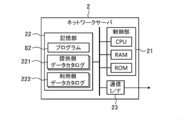
- FIG. 3 schematically illustrates an example of the hardware configuration of the network server according to the embodiment.
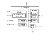
- FIG. 4 schematically illustrates an example of the hardware configuration of the user terminal according to the embodiment.
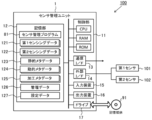
- FIG. 5 schematically illustrates an example of the software configuration of the sensor management unit according to the embodiment.
- FIG. 6 illustrates an example of a processing procedure of matching between a provider of sensing data and a user according to the embodiment.
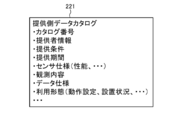
- FIG. 7A schematically illustrates an example of a provider-side data catalog according to the embodiment.
- FIG. 7B schematically illustrates an example of a use-side data catalog according to the embodiment.
- FIG. 8 illustrates an example of the processing procedure of the sensor management unit according to the embodiment.
- FIG. 9 illustrates an example of a process of managing sensing data by the sensor management unit according to the embodiment.
- FIG. 10 schematically illustrates an example of setting data according to the embodiment.
- FIG. 11 schematically illustrates the correspondence between (first) sensing data and various types of metadata according to the embodiment.
- FIG. 12 schematically illustrates an example of management data according to the embodiment.
- the present embodiment an embodiment according to one aspect of the present invention (hereinafter, also referred to as “the present embodiment”) will be described based on the drawings.
- the embodiment described below is merely an illustration of the present invention in all respects. It goes without saying that various improvements and modifications can be made without departing from the scope of the present invention. That is, in the implementation of the present invention, a specific configuration according to the embodiment may be appropriately adopted.
- data appearing in the present embodiment is described in natural language, more specifically, it is specified by a pseudo language, a command, a parameter, a machine language or the like that can be recognized by a computer.
- FIG. 1 schematically illustrates an example of a usage scene of the sensor device 100 according to the present embodiment.
- the sensor device 100 according to the present embodiment is used as a provider that provides sensing data to the user terminal 3 of the user.
- the method of using the sensor device 100 according to the present embodiment is not limited to such an example, and may be appropriately determined according to the embodiment.
- the sensor device 100 includes a first sensor 101 for observing an object, a second sensor 102 for observing a usage pattern of the first sensor 101, and a sensor management unit 1 connected to each sensor (101, 102). Is equipped.
- the first sensor 101 is an example of the “sensor” in the present invention
- the second sensor 102 is an example of the “sub-sensor” in the present invention.
- the type of each sensor (101, 102) may be selected appropriately according to the observation target.
- the sensor management unit 1 is an information processing apparatus configured to manage sensing data (first sensing data 121 described later) obtained by the first sensor 101. Specifically, the sensor management unit 1 acquires sensing data (first sensing data 121 described later) obtained by observing the target by the first sensor 101. Subsequently, the sensor management unit 1 is an attribute of the first sensor 101 at the time when the sensing data is obtained, and indicates an attribute related to the usage pattern of the first sensor 101 that can dynamically change with the passage of time. Target metadata (dynamic metadata 124 described later) is generated.
- the attribute regarding the utilization form of the 1st sensor 101 shown by dynamic metadata is an attribute regarding the operation setting of the 1st sensor 101, an attribute about the installation situation of the 1st sensor 101, etc., for example.
- Information held as dynamic metadata is not limited to a constant value, but relates to an attribute that may change depending on the usage form. That is, the dynamic metadata can be an object to confirm (or track) whether or not the use form of the first sensor 101 has changed in order to determine, for example, the reliability, validity, etc. of the sensing data. Indicates attribute information.
- the sensor management unit 1 appropriately generates such dynamic metadata.
- the use form of the first sensor 101 is monitored by the second sensor 102. Therefore, as one method of generating dynamic metadata, the sensor management unit 1 according to the present embodiment uses sensing data (described later, which is obtained by observing the usage pattern of the first sensor 101 by the second sensor 102 Dynamic metadata is generated based on the second sensing data 122). Then, the sensor management unit 1 manages the generated dynamic metadata in association with the sensing data.
- sensing data associated with dynamic metadata is provided from the sensor device 100 to the user terminal 3 of the user via the network server 2.
- a plurality of sensor devices 100 and a plurality of user terminals 3 are connected to the network server 2 via a network (not shown).
- the type of network may be appropriately selected from, for example, the Internet, a wireless communication network, a mobile communication network, a telephone network, a dedicated network, and the like.
- the network server 2 can match the provision source of the sensing data (sensor device 100) and the use destination (application software etc. executed by the user terminal 3) by a method described later, and can provide the sensing data satisfying the request of the use destination Extract the source of Then, the network server 2 permits the distribution of sensing data between the sensor device 100 in which the matching is established and the user terminal 3. Thereby, in the present embodiment, sensing data is provided from each sensor device 100 to the appropriate user terminal 3.
- the sensor management unit 1 generates, as dynamic metadata, information on the usage mode of the first sensor 101 at the time when sensing data is obtained, and generates the generated dynamic metadata. Manage in association with data. Therefore, the sensor management unit 1 sends, together with the sensing data obtained by the first sensor 101, to each user terminal 3 dynamic metadata indicating information on the usage pattern of the first sensor 101 at the time of obtaining the sensing data. Can be provided.
- each user terminal 3 checks the usage pattern of the first sensor 101 at the time when the sensing data to be used is obtained, by referring to the associated dynamic metadata when using the sensing data. Will be able to That is, in each user terminal 3, processing such as accessing the first sensor 101 to check the usage pattern of the first sensor 101, and inquiring to the sensor management unit 1 managing the first sensor 101 can be omitted. . Therefore, according to the present embodiment, it is possible to reduce the time and effort required to confirm the use form of the first sensor 101 when using the sensing data.
- FIG. 2 schematically illustrates an example of the hardware configuration of the sensor management unit 1 according to the present embodiment.
- the control unit 11, the storage unit 12, the communication interface 13, the external interface 14, the input device 15, the output device 16, and the drive 17 are electrically connected.
- the communication interface and the external interface are described as “communication I / F” and “external I / F”, respectively.
- the control unit 11 includes a hardware processor such as a central processing unit (CPU), a random access memory (RAM), and a read only memory (ROM), and is configured to execute information processing based on a program and various data.
- the storage unit 12 is an example of “memory”, and is configured of, for example, a hard disk drive, a solid state drive, or the like.
- the storage unit 12 includes a sensor management program 81, first sensing data 121, second sensing data 122, static metadata 123, dynamic metadata 124, processing metadata 125, management data 126, and setting. Data 127 and the like are stored.
- the first sensing data 121 is obtained by observing an object with the first sensor 101.
- the second sensing data 122 is obtained by observing the usage pattern of the first sensor 101 by the second sensor 102.
- Each metadata 123 to 125 relates to the first sensor 101, and is associated with the first sensing data 121.
- the management data 126 includes information indicating the correspondence between the first sensing data 121 and the metadata 123 to 125 according to the association.
- the setting data 127 includes information indicating the operation setting of the first sensor 101.
- the sensor management program 81 includes an instruction to cause the sensor management unit 1 to execute information processing (FIG. 8) for managing the first sensing data 121 and the metadata 123 to 125 described later. Details will be described later.
- the communication interface 13 is, for example, a wired LAN (Local Area Network) module, a wireless LAN module, or the like, and is an interface for performing wired or wireless communication via a network.
- the sensor management unit 1 performs data communication with the network server 2 via the communication interface 13.
- the external interface 14 is, for example, a USB (Universal Serial Bus) port, a dedicated port, or the like, and is an interface for connecting to an external device.
- the type and number of external interfaces 14 may be appropriately selected in accordance with the type and number of external devices to be connected.
- the sensor management unit 1 is connected to each sensor (101, 102) via the external interface 14.
- the type of the first sensor 101 may not be particularly limited, and may be appropriately selected according to the embodiment.
- the first sensor 101 may be, for example, an image sensor, an infrared sensor, a sound sensor, an optical sensor, a pressure sensor, an atmospheric pressure sensor, a temperature sensor, or the like.
- the first sensor 101 may be, for example, an environment sensor, a vital sensor, an on-vehicle sensor, a home security sensor, or the like.
- the environmental sensor is a sensor configured to be able to measure or detect environmental information related to atmospheric pressure, temperature, humidity, sound pressure, sound, ultraviolet light, illuminance, rainfall, gas and the like.
- the vital sensor is a sensor configured to be able to measure or detect vital information such as blood pressure, heart rate, electrocardiogram, body temperature, sleep state (microwave), activity amount, blood glucose level and the like.
- An on-vehicle sensor is a sensor mounted in vehicles, such as an image sensor, a laser sensor, and a sleep (microwave) sensor.
- Home security sensors include home sensors such as image sensors, infrared sensors, activity (voice) sensors, gas (CO 2 etc.) sensors, current sensors, smart meters (sensors that measure the amount of power used by home appliances, lighting, etc.)
- the sensor is configured to measure or detect information related to Accordingly, the first sensing data 121 obtained by the first sensor 101 is, for example, image data, numerical data, voice data, language data, and the like.
- the first sensor 101 is appropriately disposed so as to be able to observe the state of the object.
- the type of the second sensor 102 may not be particularly limited as long as the usage mode of the first sensor 101 can be observed, and may be appropriately selected according to the embodiment.
- the second sensor 102 may be, for example, a temperature sensor, a GPS sensor, an acceleration sensor, an atmospheric pressure sensor, a geomagnetic sensor, a gyro sensor, or the like.
- the second sensor 102 is appropriately disposed so as to be able to observe the usage pattern of the first sensor 101.
- a temperature sensor is employed as the second sensor 102
- the second sensor 102 can observe the temperature around the first sensor 101. it can.
- the second sensor 102 is attached to a housing (not shown) of the first sensor 101, whereby the attitude of the first sensor 101 is For example, the direction can be observed.
- one first sensor 101 and one second sensor 102 are connected to the sensor management unit 1.
- the number of each of the first sensor 101 and the second sensor 102 connected to the sensor management unit 1 may not be limited to one, and may be two or more.
- a plurality of first sensors 101 may be connected to the sensor management unit 1.
- a plurality of second sensors 102 may be used.
- the number of sensors (101, 102) connected to the sensor management unit 1 may be appropriately determined according to the embodiment.
- the input device 15 is, for example, a device for performing input such as a mouse and a keyboard.
- the output device 16 is, for example, a device for outputting a display, a speaker or the like. A user who is a provider of sensing data can operate the sensor management unit 1 using the input device 15 and the output device 16.
- the drive 17 is, for example, a CD drive, a DVD drive, or the like, and is a drive device for reading a program stored in the storage medium 91.
- the type of drive 17 may be appropriately selected according to the type of storage medium 91.
- the sensor management program 81 may be stored in the storage medium 91.
- the storage medium 91 stores information such as a program by an electric, magnetic, optical, mechanical or chemical action so that information such as a computer or other device or program recorded on a machine can be read.
- the sensor management unit 1 may obtain the sensor management program 81 from the storage medium 91.
- a disc-type storage medium such as a CD or a DVD is illustrated.
- the type of storage medium 91 is not limited to the disc type, and may be other than the disc type.
- a storage medium other than the disk type for example, a semiconductor memory such as a flash memory can be mentioned.
- the control unit 11 may include a plurality of hardware processors.
- the hardware processor may be configured by a microprocessor, a field-programmable gate array (FPGA), a digital signal processor (DSP), and the like.
- the storage unit 12 may be configured by a RAM and a ROM included in the control unit 11.
- the input device 15 and the output device 16 may be omitted.
- the sensor management unit 1 may be connected to each sensor (101, 102) via the communication interface 13, not the external interface 14. In this case, the external interface 14 may be omitted.
- the sensor management unit 1 is comprised by one information processing apparatus in FIG. 2, you may be comprised by two or more information processing apparatuses.
- the hardware configuration of each information processing device may or may not match.
- the sensor management unit 1 may be a general-purpose desktop PC (Personal Computer), a tablet PC, a smartphone, a mobile phone other than a smartphone, a programmable logic controller (PLC), etc., in addition to an information processing device designed specifically for services. Good.
- PLC programmable logic controller
- FIG. 3 schematically illustrates an example of the hardware configuration of the network server 2 according to the present embodiment.
- the network server 2 is a computer to which the control unit 21, the storage unit 22, and the communication interface 23 are electrically connected.
- the communication interface is described as "communication I / F".
- control unit 21 includes a hardware processor such as a CPU, a RAM, and a ROM, and is configured to execute various information processing based on programs and data.
- the storage unit 22 includes, for example, a hard disk drive, a solid state drive, and the like, and stores the program 82, the providing side data catalog 221, the using side data catalog 222, and the like.
- the program 82 includes an instruction to cause the network server 2 to execute information processing (FIG. 6) for matching a provider and a use destination described later.
- the provider data catalog 221 is prepared for each provider and includes information indicating sensing data (first sensing data 121) that can be provided by the sensor (first sensor 101) of each sensor device 100.
- the use-side data catalog 222 is prepared for each use destination, and includes information indicating sensing data desired by the user.
- the provider data catalog 221 and the user data catalog 222 are used for matching of a provider and a user. Details will be described later.
- the communication interface 23, like the communication interface 13, is an interface for performing communication via a network.
- the communication interface 23 is, for example, a wired LAN module, a wireless LAN module, or the like.
- the network server 2 performs data communication with each sensor device 100 and each user terminal 3 via the communication interface 23.
- control unit 21 may include a plurality of hardware processors.
- the hardware processor may be configured by a microprocessor, an FPGA or the like.
- the storage unit 22 may be configured by a RAM and a ROM included in the control unit 21.
- the network server 2 may further include an input device and an output device as a user interface.
- the network server 2 may be a general-purpose server device, a general-purpose PC, or the like, in addition to an information processing device designed for service only.
- FIG. 4 schematically illustrates an example of the hardware configuration of the user terminal 3 according to the present embodiment.
- the user terminal 3 is a computer in which the control unit 31, the storage unit 32, the communication interface 33, the input device 34, and the output device 35 are electrically connected.
- the communication interface is described as “communication I / F” as in FIGS. 2 and 3.
- the control unit 31 includes a CPU that is a hardware processor, a RAM, a ROM, and the like, similarly to the control units (11, 22), and is configured to execute various information processing based on programs and data.
- the storage unit 32 includes, for example, a hard disk drive, a solid state drive, and the like, and stores the application program 83 and the like.
- the application program 83 includes an instruction to cause the control unit 31 to execute predetermined information processing, and uses sensing data (first sensing data 121) provided from each user terminal 3.
- the type of application program 83 may not be particularly limited, and may be appropriately selected according to the embodiment.
- the communication interface 33 is an interface for performing communication via a network, similarly to the above-described communication interfaces (13, 23).
- the communication interface 33 is, for example, a wired LAN module, a wireless LAN module, or the like.
- the user terminal 3 performs data communication with the network server 2 via the communication interface 33.
- the input device 34 is, for example, a device for performing an input such as a mouse and a keyboard as the input device 15 described above.
- the output device 35 is, for example, a device for outputting a display, a speaker, and the like, as in the case of the output device 16.
- the user of the sensing data can operate the user terminal 3 using the input device 34 and the output device 35.
- control unit 31 may include a plurality of hardware processors.
- the hardware processor may be configured by a microprocessor, an FPGA, or the like.
- the storage unit 32 may be configured by a RAM and a ROM included in the control unit 31.
- the user terminal 3 may be a general-purpose desktop PC, a tablet PC, a smartphone, a mobile phone other than a smartphone, or the like, in addition to an information processing apparatus designed specifically for service.
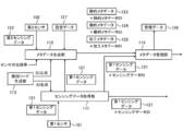
- FIG. 5 schematically illustrates an example of the software configuration of the sensor management unit 1 according to the present embodiment.
- the control unit 11 of the sensor management unit 1 deploys the sensor management program 81 stored in the storage unit 12 in the RAM. Then, the control unit 11 causes the CPU to interpret the sensor management program 81 expanded in the RAM, and executes information processing based on the interpretation while controlling each component.
- the sensor management unit 1 includes, as software modules, a sensing data acquisition unit 111, a metadata generation unit 112, an identification code generation unit 113, a metadata management unit 114,
- the configuration is configured as a computer including the first communication unit 115, the second communication unit 116, and the catalog change unit 117.
- the sensing data acquisition unit 111 acquires the first sensing data 121 obtained by observing the target by the first sensor 101.
- the metadata generation unit 112 is an attribute of the first sensor 101 at the time when the first sensing data 121 is obtained, and indicates an attribute related to the usage pattern of the first sensor 101 that can dynamically change with the passage of time. Dynamic metadata 124 is generated. In the present embodiment, the metadata generation unit 112 generates the dynamic metadata 124 based on the second sensing data 122 and the like obtained by observing the usage pattern of the first sensor 101 by the second sensor 102. .
- the metadata generation unit 112 generates static metadata 123 and processing metadata 125 in addition to the dynamic metadata 124.
- the static metadata 123 indicates an attribute related to the specification of the first sensor 101 that does not change with time. That is, the information held as the static metadata 123 basically relates to an attribute whose value is always constant and which is not likely to change depending on the usage form.
- the processing metadata 125 relates to the feature amount of the acquired first sensing data 121, and is generated by analyzing the acquired first sensing data 121.
- the identification code generation unit 113 includes a first identification code (sensing data ID described later) for identifying the first sensing data 121, and a second identification code (static described later for identifying each of the metadata 123 to 125). Metadata ID, Dynamic Metadata ID, and Processed Metadata ID) are generated.
- the metadata management unit 114 manages the generated metadata 123 to 125 in association with the first sensing data 121.
- the first communication unit 115 transmits the first sensing data 121 to an external device such as each user terminal 3 or the like.
- the second communication unit 116 transmits the metadata 123 to 125 to the external device.
- the catalog changing unit 117 changes the contents of the provider data catalog 221 stored in the network server 2 in accordance with the change of the usage pattern of the first sensor 101.
- each software module of the sensor management unit 1 will be described in detail in an operation example described later.
- an example in which each software module of the sensor management unit 1 is realized by a general-purpose CPU is described.
- the method of implementing each software module may not be limited to such an example.
- Some or all of the software modules may be implemented by one or more dedicated processors. Further, regarding the software configuration of the sensor management unit 1, omission, replacement, and addition of software modules may be appropriately performed according to the embodiment.
- FIG. 6 shows an example of a processing procedure of matching by the network server 2 according to the present embodiment.
- the processing procedure of the matching described below is only an example, and each processing may be changed as much as possible.
- steps may be omitted, replaced, or added as appropriate, according to the embodiment.
- Step S11 and S12 First, in step S ⁇ b> 11, the control unit 21 of the network server 2 acquires a providing-side data catalog 221 indicating sensing data that can be provided by each sensor device 100. In the next step S12, the control unit 21 acquires the use-side data catalog 222 indicating the sensing data desired by the user.
- FIG. 7A schematically illustrates an example of the provider-side data catalog 221 according to the present embodiment.
- the provider-side data catalog 221 according to the present embodiment includes information such as catalog number, provider information, provision condition, provision period, sensor specification, observation content, data specification, usage form and the like.
- the control unit 21 may appropriately generate the provider data catalog 221 by acquiring various information registered in the provider data catalog 221.
- the catalog number is a number for identifying the provider data catalog 221.
- the control unit 21 may appropriately generate an arbitrary number not used for the other providing side data catalog 221, and set the generated number as the catalog number.
- provider information is information for specifying the provider of sensing data, For example, a provider's name (personal name or organization name), a provider's contact point etc. may be included.
- the information on the provision conditions defines the conditions under which the provision of sensing data is permitted.
- the provision conditions include, for example, usage of sensing data (commercial / non-commercial / no restriction), scope of provision (providing to third party / not permitted), access right (replication impossible / replication possible / modification possible / processable) Conditions such as presence or absence of personal information, presence or absence of anonymous processing information, and payment types of expenses for use of sensing data may be included.
- Information on the provision period defines a period for which provision of sensing data is permitted (for example, the start date and end date of the provision).
- the control unit 21 receives the input or designation from the provider via each sensor device 100 or other information processing apparatus when generating the provider-side data catalog 221, thereby providing provider information, provision conditions, and provision. You may acquire each information of a period.
- the information on the sensor specification indicates an attribute on the specification of the first sensor 101, and may include, for example, information on the performance of the first sensor 101, device information, information on an initial installation condition, and the like.
- the information related to the performance of the first sensor 101 may include, for example, information such as the sensitivity limit of the first sensor 101, the dynamic range, the settable range of the spatial resolution, and the settable range of the sampling frequency.
- the device information of the first sensor 101 may include, for example, information such as the name of the first sensor 101, the description of the first sensor 101, and the like.
- the information on the initial installation condition of the first sensor 101 may include, for example, information such as a proper noun of the installation place of the first sensor 101.
- the information about the observation content indicates the attribute of the observation performed using the first sensor 101, and, for example, the name of the observation (for example, environmental observation), the explanation about the observation, and the name of the target for observation (for example, A establishment) ,
- the description about the observation object, the name of the observation index (for example, temperature, humidity, etc.), the explanation about the observation index, etc. may be included.
- the data specification information indicates an attribute related to the specification of the first sensing data 121 obtained by the first sensor 101.
- the name of the observed value (temperature value, maximum power consumption value, etc.) indicated by the first sensing data 121, It may include information such as the explanation of the observation value and the unit of the observation value.
- the control unit 21 When the control unit 21 generates the provider-side data catalog 221, the sensor specification, the observation content, and the data specification are obtained from the static metadata 123 associated with the first sensor 101 or the first sensing data 121 of each sensor device 100. Of each information may be acquired.
- the information on the usage mode indicates an attribute of the first sensor 101 that may change according to the usage mode, and may include, for example, information on operation setting of the first sensor 101 and information on the installation status of the first sensor 101 .
- the information on the operation setting of the first sensor 101 may include, for example, information such as a set value of the measurement range of the first sensor 101, a set value of resolution of the measurement range, and a set value of the sampling frequency.
- the information on the installation state of the first sensor 101 may include, for example, information such as the installation angle of the first sensor 101, the temperature around the first sensor 101, and the distance between the first sensor 101 and the observation target. Good.
- the control unit 21 may obtain information on the usage form from the dynamic metadata 124 associated with each sensor device 100 or the first sensing data 121.
- FIG. 7B schematically illustrates an example of the use-side data catalog 222 according to the present embodiment.
- the use-side data catalog 222 according to the present embodiment includes information such as catalog number, user information, collection condition, use period, sensor specification, observation content, data specification, use form and the like.
- the control unit 21 receives input or designation from the user via each user terminal 3 or other information processing apparatus, and acquires various information to be registered in the use-side data catalog 222.
- the data catalog 222 may be generated as appropriate.
- the catalog number is the same as the catalog number of the provider data catalog 221.
- each information of user information, collection condition, use period, sensor specification, observation content, data specification, and use form is the provider information of the above-mentioned provider data catalog 221, provision condition, provision period, sensor specification, observation It corresponds to each information of content, data specification, and usage form.
- the user information is information for identifying the user of the sensing data.
- the information on receipt conditions defines conditions for accepting provision of sensing data.
- the information on the usage period defines a period (for example, start date and time and usage end date and time of use) for which provision of sensing data is desired or desired to be provided.
- the information on the sensor specification indicates an attribute on the specification of the sensor for which it is desired to provide sensing data.
- the information on the content of observation indicates the attribute of the observation for which it is desired to provide sensing data.
- the data specification information indicates an attribute related to the specification of sensing data desired to be provided.
- the information on the use form indicates an attribute that may change according to the use form of the sensor for which provision of sensing data is desired.
- each information of user information, collection condition, usage period, sensor specification, observation content, data specification, and usage form are the provider information of the above-mentioned provider data catalog 221, provision condition, provision period, sensor It may be the same as the information of the specification, the observation content, the data specification, and the usage form.
- the generation of the provider data catalog 221 and the user data catalog 222 may not be performed by the network server 2.
- the provider data catalog 221 may be generated by each sensor device 100 or another information processor of the provider.
- the use-side data catalog 222 may be generated by each user terminal 3 or another information processing apparatus of the user.
- the control unit 21 may acquire the provider data catalog 221 from each sensor device 100 or another information processor of the provider via the network.
- the control unit 21 may acquire the use-side data catalog 222 from each user terminal 3 or another information processing apparatus of the user via the network.
- Steps S13 and S14 In the next step S13, the control unit 21 matches the provision source with the use destination by collating each item of the provision side data catalog 221 with each item of the use side data catalog 222. In the next step S14, based on the result of the matching, the sensor device 100 (first sensor 101) capable of providing sensing data (first sensing data 121) satisfying the user's request is extracted.
- the control unit 21 provides the provision condition of the provider data catalog 221, the provision period, the sensor specification, the observation content, the data specification, the collection condition of each item of the usage form and the usage data catalog 222, and uses Each item of a period, a sensor specification, an observation content, a data specification, and a utilization form is collated, and it is determined whether each item is suitable. As a result of the determination, when all or part of the items match, the control unit 21 senses the sensor device 100 corresponding to the provider data catalog 221 to satisfy the user request corresponding to the user data catalog 222. Extract data as available.
- control unit 21 determines that the sensor device 100 corresponding to the provider-side data catalog 221 can not provide sensing data satisfying the request of the user corresponding to the user-side data catalog 222 Do.
- the method of matching may not be limited to such an example, and may be appropriately determined according to the embodiment.
- Step S15 the control unit 21 permits the distribution of the sensing data (first sensing data 121) from the extracted sensor device 100 to the target user terminal 3.
- the control unit 21 transmits, to the extracted sensor device 100, a data flow permission instruction indicating that transmission of sensing data to the target user terminal 3 is permitted.
- each sensor device 100 transmits the first sensing data 121 obtained by observing the target with the first sensor 101 to the target user terminal 3 specified by the data flow permission command.
- the control unit 21 ends the matching process according to the present operation example.
- FIG. 8 illustrates an example of a processing procedure for managing the first sensing data 121 by the sensor management unit 1 according to the present embodiment.
- FIG. 9 schematically illustrates an example of a management process of the first sensing data 121 by the sensor management unit 1 according to the present embodiment.
- the processing procedure described below is an example of the “sensor management method” in the present invention. However, the processing procedure described below is merely an example, and each processing may be changed as much as possible. In addition, according to the embodiment, steps may be omitted, replaced, or added as appropriate, according to the embodiment.
- Step S101 First, in step S101, the control unit 11 of the sensor management unit 1 operates as the sensing data acquisition unit 111, and acquires the first sensing data 121 obtained by observing the target by the first sensor 101.
- the sensor management unit 1 holds setting data 127 indicating the operation setting of the first sensor 101. Therefore, the control unit 11 refers to the setting data 127 to specify the operation setting of the first sensor 101.
- FIG. 10 schematically illustrates an example of the setting data 127 according to the present embodiment.
- the setting data 127 includes, for example, information such as a setting value of the measurement range, a setting value of the resolution of the measurement range, and a setting value of the sampling frequency as information indicating the operation setting of the first sensor 101.
- the control unit 11 controls the operation of the first sensor 101 based on these pieces of information.
- control unit 11 controls the operation of the first sensor 101 based on the setting value of the measurement range indicated by the setting data 127 and the setting value of the resolution. Then, the control unit 11 sets a setting value indicated by the setting data 127 as a sampling frequency, and performs sampling processing of a signal output from the first sensor 101. Thereby, the control unit 11 can acquire the first sensing data 121.
- the method of acquiring the first sensing data 121 may not be limited to such an example, and may be appropriately determined according to the embodiment.
- control and sampling processing of the first sensor 101 may be performed by another information processing apparatus.
- the control unit 11 may acquire the first sensing data 121 from the other information processing apparatus.
- the control unit 11 proceeds to the next step S102.
- the first sensing data 121 may be configured to be time-series data having a certain time width, or may be configured to indicate an observation result of a temporary point.
- the configuration of the first sensing data 121 may not be particularly limited, and may be appropriately determined according to the embodiment.
- Step S102 In the next step S102, the control unit 11 operates as the identification code generation unit 113, and generates a sensing data ID for identifying the first sensing data 121 acquired in step S101.
- the sensing data ID is an example of the “first identification code”.
- the configuration of the sensing data ID may not be particularly limited, and may be appropriately determined according to the embodiment.
- the control unit 11 senses an arbitrary character string different from the character string of the sensing data ID which is not attached to the other first sensing data 121, that is, paired with the other first sensing data 121. You may generate suitably as data ID.
- the control unit 11 pairs the generated sensing data ID with the first sensing data 121 acquired in step S101. Thus, when the generation of the sensing data ID is completed, the control unit 11 proceeds to the next step S103.
- Step S103 In the next step S103, the control unit 11 operates as the metadata generation unit 112, and generates static metadata 123, dynamic metadata 124, and processing metadata 125. After generating the metadata 123 to 125, the control unit 11 advances the process to the next step S104.
- the static metadata 123 is configured to indicate an attribute related to the specification of the first sensor 101, which does not change as time passes, as described above. As long as it is configured as such, the contents of the static metadata 123 may be appropriately determined according to the embodiment.
- the static metadata 123 may include, for example, an attribute related to the performance of the first sensor 101, an attribute related to device information of the first sensor 101, an attribute related to an initial installation condition of the first sensor 101, and the like.
- the control unit 11 obtains information corresponding to each item from the first information sensor 101 or another information processing apparatus that holds information on the specification of the first sensor 101, and generates static metadata 123 based on the obtained information. You may
- Dynamic metadata Dynamic metadata 124 is an attribute of the first sensor 101 at the time when the first sensing data 121 is obtained, as described above, and can be dynamically changed with the passage of time. It is configured to indicate an attribute related to the usage pattern of the first sensor 101. As long as it is configured as such, the contents of the dynamic metadata 124 may be appropriately determined according to the embodiment.
- the attribute relating to the usage form of the first sensor 101 indicated by the dynamic metadata 124 may include, for example, an attribute relating to the operation setting of the first sensor 101, an attribute relating to the installation state of the first sensor 101, and the like.
- the attributes related to the operation setting of the first sensor 101 are, for example, a set value of the measurement range, a set value of the resolution of the measurement range, a set value of the sampling frequency, and the like.
- information on the operation setting of the first sensor 101 is stored in the storage unit 12 as setting data 127. Therefore, the control unit 11 may acquire the information related to the operation setting of the first sensor 101 by referring to the setting data 127, and may generate the dynamic metadata 124 based on the acquired information.
- the attribute regarding the installation condition of the first sensor 101 is, for example, an installation angle of the first sensor 101, a temperature around the first sensor 101, a distance between the first sensor 101 and an observation target, and the like.
- the use form of the first sensor 101 is monitored by the second sensor 102 connected to the sensor management unit 1. Therefore, the control unit 11 may generate the dynamic metadata 124 based on the second sensing data 122 obtained by observing the usage pattern of the first sensor 101 by the second sensor 102.
- the second sensing data 122 obtained by the second sensor 102 is the temperature around the first sensor 101 Show. Therefore, even if the control unit 11 acquires the second sensing data 122 and generates data indicating the temperature around the first sensor 101 as the dynamic metadata 124 based on the acquired second sensing data 122. Good.
- the control unit 11 may acquire the second sensing data 122 and generate data indicating the installation angle of the first sensor 101 as the dynamic metadata 124 based on the acquired second sensing data 122. .
- the configuration of the dynamic metadata 124 may not be limited to such an example, and may be appropriately determined according to the embodiment. For example, at least one of the information on the attribute related to the operation setting of the first sensor 101 and the information on the attribute related to the installation status may be omitted. Also, the dynamic metadata 124 may include information on attributes regarding the usage form of the first sensor 101 other than the information on the attribute regarding the operation setting of the first sensor 101 and the information about the attribute regarding the installation status.
- control unit 11 may generate the dynamic metadata 124 regardless of the setting data 127 and the second sensing data 122.
- the control unit 11 may generate the dynamic metadata 124 based on the first sensing data 121.
- the control unit 11 analyzes the first sensing data 121 to specify the distance between the first sensor 101 and the observation target, and the specified distance May be generated as dynamic metadata 124.
- the dynamic metadata 124 is configured to indicate an attribute related to the usage pattern of the first sensor 101 at the time when the first sensing data 121 is obtained. Therefore, it is preferable that the point in time of the usage pattern of the first sensor 101 indicated by the dynamic metadata 124 coincide with the point in time when the first sensing data 121 is obtained. However, this “when the first sensing data 121 is obtained” may not be exact.
- the time of the usage pattern of the first sensor 101 indicated by the dynamic metadata 124 and the time of obtaining the first sensing data 121 may not completely coincide, and the dynamic metadata 124 They may be offset from each other as long as they do not have a fatal impact on usage.
- the point of time of usage of the first sensor 101 indicated by the dynamic metadata 124 and the point of time when the first sensing data 121 are obtained deviate from each other to such an extent that the utilization of the dynamic metadata 124 is not adversely affected. Is also included in the "point when the first sensing data 121 is obtained".
- control unit 11 may acquire the setting data 127 and the second sensing data 122 used to generate the dynamic metadata 124 at the same timing as the first sensing data 121, or the first sensing data 121. And may be acquired at different timings.
- the method of acquiring the second sensing data 122 may be the same as the method of acquiring the first sensing data 121 in step S101.
- the processed metadata 125 is configured to indicate the feature value of the first sensing data 121 acquired in step S101 as described above. As long as it is configured as such, the content of the processing metadata 125 may be appropriately determined according to the embodiment.
- the control unit 11 can generate processing metadata 125 by executing a predetermined analysis process on the first sensing data 121 acquired in step S101.
- the type of predetermined analysis processing when generating the processing metadata 125 may not be particularly limited, and may be appropriately selected according to the embodiment.
- the predetermined analysis processing may be, for example, labeling processing, arithmetic processing for deriving a variation, arithmetic processing for deriving a vector value, conversion processing, cleansing processing, filtering processing, and the like.
- the conversion process is an arithmetic process for aligning units, scales, and the like. Cleansing processing is arithmetic processing for removing data other than the true value of sensing data.
- the filtering process is an arithmetic process for applying a filter such as an LPF, an HPF, or a BPF to sensing data.
- the type of the feature amount obtained as the processing metadata 125 by the analysis processing is not particularly limited as long as it indicates the feature of the first sensing data 121 acquired in step S101, and according to the embodiment May be selected appropriately.
- the feature amount obtained as the processing metadata 125 may be, for example, a label, a change amount, a vector value, an outlier, or the like.
- the contents of the dynamic metadata 124 and the processing metadata 125 depend on the timing and content of acquiring the first sensing data 121. Therefore, the control unit 11 newly generates the dynamic metadata 124 and the processing metadata 125 with respect to the acquired first sensing data 121 each time the processing of steps S101 to S103 is repeated.
- the content of the static metadata 123 does not depend on the first sensing data 121. Therefore, after creating the static metadata 123 once, the control unit 11 does not have to newly create the static metadata 123 for the same first sensor 101. That is, the control unit 11 may generate the static metadata 123 only when the present step S103 is executed for the first time.
- the timing of generating the static metadata 123 may be different from the timing of executing the present step S103.
- the control unit 11 connects, for example, the first sensor 101 to the sensor management unit 1 before executing step S101, and sets the static meta to the sensor management unit 1 at the time of initial setting for registering the first sensor 101. Data 123 may be generated.
- Step S104 In the next step S104, the control unit 11 operates as the identification code generation unit 113, and is used to identify each of the static metadata 123, the dynamic metadata 124, and the processing metadata 125 generated in step S103.
- the target metadata ID, the dynamic metadata ID, and the processing metadata ID are generated.
- Each metadata ID is an example of the “second identification code”.
- each metadata ID may not be particularly limited, and may be appropriately determined according to the embodiment.
- the control unit 11 can generate each metadata ID in the same manner as the sensing data ID.
- the control unit 11 pairs the generated static metadata ID with the static metadata 123 generated in step S103.
- the control unit 11 pairs the generated dynamic metadata ID with the dynamic metadata 124 generated in step S103.
- the control unit 11 pairs the generated processing metadata ID with the processing metadata 125 generated in step S103.
- the control unit 11 advances the process to the next step S105.
- the static metadata 123 may be generated before performing step S101. Therefore, the timing at which the static metadata ID is generated may be different from the timing at which the present step S104 is performed.
- the control unit 11 connects, for example, the first sensor 101 to the sensor management unit 1 before executing step S101, and sets the static meta to the sensor management unit 1 at the time of initial setting for registering the first sensor 101.
- a data ID may be generated.
- Step S105 In the next step S105, the control unit 11 operates as the metadata management unit 114, and associates the metadata 123 to 125 generated in step S103 with the first sensing data 121 acquired in step S101.
- a sensing data ID is generated for the first sensing data 121
- each metadata ID is generated for each of the metadata 123 to 125. Therefore, the control unit 11 associates each metadata 123 to 125 with the first sensing data 121 using the sensing data ID and each metadata ID.
- the control unit 11 updates the management data 126 by adding the result of the association to the management data 126.
- the control unit 11 manages the correspondence between each of the metadata 123 to 125 and the first sensing data 121.
- FIG. 11 schematically illustrates the correspondence between the first sensing data 121 and each of the metadata 123 to 125.
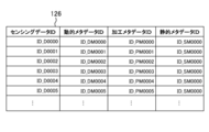
- FIG. 12 schematically illustrates an example of the management data 126 according to the present embodiment. 11 and 12, the dynamic metadata 124 and the processing metadata 125 are newly generated each time the first sensing data 121 is acquired, whereas the static metadata 123 is one time. An example will not be newly generated after being generated.
- the first sensing data 121 such as "D0000” is acquired, and accordingly, the sensing data ID such as "ID_D0000” is each first sensing data 121. It is tied to.
- dynamic metadata 124 such as “DM0000” and processed metadata 125 such as "PM0000” are generated for each first sensing data 121. Accordingly, dynamic metadata IDs such as “ID_DM0000” are linked to each dynamic metadata 124, and process metadata IDs such as “ID_PM0000” are linked to each process metadata 125.
- static metadata 123 “SM 0000” is generated, and in response to this, static metadata ID “ID_SM 0000” is linked to the static metadata 123.
- the control unit 11 associates the dynamic metadata 124 and the processing metadata 125 with the corresponding first sensing data 121.
- the dynamic metadata 124 “DM 000 n” and the processing metadata 125 “PM 000 n” are associated with the first sensing data 121 “D 000 n” (n is 0 to 5).
- the control unit 11 commonly associates the static metadata 123 with each first sensing data 121.
- the static metadata “SM 0000” is associated with each first sensing data 121 “D 000 n” (n is 0 to 5).
- the control unit 11 stores, as management data 126, information indicating the correspondence by the association.
- each record (row data) of the management data 126 indicates the correspondence by each association.
- each record of the management data 126 has a field for storing each of the sensing data ID, the dynamic metadata ID, the processing metadata ID, and the static metadata ID.
- the control unit 11 can add the result of the association to the management data 126 by storing the associated first sensing data 121 and the IDs of the metadata 123 to 125 in the fields of the new record.
- the management data 126 is expressed in a table format.
- the data format of the management data 126 may not be limited to such a table format, and may be appropriately selected according to the embodiment.
- control unit 11 can associate each of the metadata 123 to 125 with the first sensing data 121. Further, the correspondence relationship by the association is managed by the management data 126. After these processes are completed, the control unit 11 advances the process to the next step S106.
- Step S106 In the next step S106, the control unit 11 stores the first sensing data 121 and the metadata 123 to 125 in the storage unit 12. After the storage process is completed, the control unit 11 advances the process to the next step S107.
- the control unit 11 may store the first sensing data 121 in the storage unit 12 at an arbitrary timing.
- the control unit 11 may store the metadata 123 to 125 in the storage unit 12 at an arbitrary timing after generating the metadata 123 to 125.
- Step S107 the control unit 11 operates as the first communication unit 115, and transmits the first sensing data 121 acquired in step S101 to the user terminal 3 permitted to be distributed by the network server 2. At this time, the control unit 11 may transmit the sensing data ID to the user terminal 3 together with the first sensing data 121.
- control unit 11 operates as the second communication unit 116, and transmits the metadata 123 to 125 generated in step S103 to the user terminal 3. At this time, similarly to the first sensing data 121, the control unit 11 may transmit each metadata ID to the user terminal 3 together with each metadata 123 to 125.
- the first communication unit 115 communicates with the external device (user terminal 3) through the first communication port in order to reduce the load for data transmission, while the second communication unit 116 does not communicate with the first device.
- the second communication port different from the communication port may communicate with the external device. That is, while the control unit 11 transmits the first sensing data 121 to the user terminal 3 through the first communication port, the control unit 11 transmits the metadata 123 to 125 to the user terminal 3 through the second communication port. It is also good.
- the communication port is an endpoint for data communication.
- the control unit 11 transmits the first sensing data 121 and the metadata 123 to 125 at different communication ports by specifying different port numbers using TCP (Transmission Control Protocol) or UDP (User Datagram Protocol). Can.
- TCP Transmission Control Protocol
- UDP User Datagram Protocol
- the ports for transmitting the first sensing data 121 and the metadata 123 to 125 may not be limited to such an example, and may be the same.
- control unit 11 may transmit the first sensing data 121 and each of the metadata 123 to 125 to the target user terminal 3 through the network server 2, or the target without the network server 2. It may be transmitted directly to the user terminal 3 of When transmitting via the network server 2, the network server 2 transfers the first sensing data 121 and the metadata 123 to 125 received from each sensor management unit 1 to the target user terminal 3.
- the timing of transmitting the first sensing data 121 and the timing of transmitting each of the metadata 123 to 125 may be simultaneous or may be different from each other. Furthermore, the timings of transmitting the metadata 123 to 125 may be simultaneous or may be different from each other. The timings of transmitting the first sensing data 121 and the metadata 123 to 125 may be appropriately determined according to the embodiment.
- the control unit 11 ends the series of processes according to the present operation example.
- the application program 83 can use the first sensing data 121 and the metadata 123 to 125.
- the control unit 11 may execute the process from step S101 again. That is, the control unit 11 may repeatedly execute the series of processes of steps S101 to S107 until the observation of the target by the first sensor 101 is completed.
- the processing procedure for sensor management according to the present operation example may be changed as much as possible.
- the series of processes of steps S101 to S106 and the process of step S107 may be performed at different timings.
- the process of step S102 may be performed later than the process of step S103.
- the control unit 11 may execute the process of association in step S105.
- control unit 11 operates as the catalog changing unit 117, and A command may be sent to the network server 2 to change the content of the usage pattern to conform to the content of the generated dynamic metadata 124.
- a command may be sent to the network server 2 to change the content of the usage pattern to conform to the content of the generated dynamic metadata 124.
- the method of updating the contents of the usage form of the provider-side data catalog 221 may not be limited to such an example.
- the network server 2 does not wait for such an instruction and receives it from each sensor management unit 1. Based on the contents of the dynamic metadata 124, the information on the usage pattern of the target provider data catalog 221 may be changed.
- control unit 11 may receive a change in the operation setting of the first sensor 101 from the user via the network server 2, each user terminal 3, or another information processing apparatus.
- the information on the use form of the use-side data catalog 222 may be used to designate the change content of the operation setting of the first sensor 101. That is, the control unit 11 may receive, as a command instructing change of the operation setting of the first sensor 101, information related to the use form of the use-side data catalog 222.
- control unit 11 may correct the content of the setting data 127 to the content specified by the user, and change the operation setting of the first sensor 101 when acquiring the first sensing data 121.
- the operation setting of the first sensor 101 can be changed according to the request of each user.
- step S107 information on the usage pattern of the first sensor 101 at the time when the first sensing data 121 is obtained is generated as the dynamic metadata 124 by the processing of steps S101 to S105.
- the target metadata 124 is managed in association with the first sensing data 121. Therefore, in step S107, together with the first sensing data 121 obtained by the first sensor 101, the dynamic metadata 124 indicating information on the usage pattern of the first sensor 101 at the time when the first sensing data 121 is obtained is It can be provided to each user terminal 3.
- each user terminal 3 refers to the associated dynamic metadata 124 to obtain the first sensor at the time when the first sensing data 121 to be used is obtained.
- the usage form of 101 can be confirmed. That is, in each user terminal 3, processing such as accessing the first sensor 101 to check the usage pattern of the first sensor 101, and inquiring to the sensor management unit 1 managing the first sensor 101 can be omitted. . Therefore, according to the present embodiment, when using the first sensing data 121, it is possible to reduce the time and effort required to confirm the usage pattern of the first sensor 101.
- Each user terminal 3 can use the dynamic metadata 124 to determine the reliability, validity, and the like of the first sensing data 121. Furthermore, each user terminal 3 can track whether or not the usage pattern of the target first sensor 101 has been changed by continuously acquiring the dynamic metadata 124.
- the static metadata 123 is generated, and the generated static metadata 123 is associated with the first sensing data 121.
- each user terminal 3 can search the first sensing data 121 based on the specification of the first sensor 101 by acquiring the static metadata 123. Therefore, according to the present embodiment, the searchability of the first sensing data 121 can be enhanced by providing the static metadata 123.
- processing metadata 125 is generated, and the generated processing metadata 125 is associated with the first sensing data 121.
- each user terminal 3 refers to the associated processing metadata 125 when using the first sensing data 121, so that the first sensing data 121 can be obtained without performing predetermined analysis processing. Feature quantities can be acquired. Therefore, according to the present embodiment, in each user terminal 3, the analysis processing for deriving the feature value of the first sensing data 121 can be omitted, and the processing load for using the first sensing data 121 can be reduced. be able to.
- step S103 dynamic metadata 124 can be appropriately generated based on the second sensing data 122 obtained by the second sensor 102.
- the sensor device 100 (sensor management unit 1) is connected to the network server 2 via the network, and the first sensing data 121 is sent to the user terminal 3 of each user according to the result of matching by the network server 2.
- the method of providing the first sensing data 121 may not be limited to such an example, and may be appropriately determined according to the embodiment.
- the first sensing data 121 and the metadata 123 to 125 may be stored in a storage medium, and may be provided to an external device via the storage medium.
- at least one of the first communication unit 115 and the second communication unit 116 may be omitted.
- the sensor management unit 1 may not include the first communication unit 115 and the second communication unit 116, but may include one communication unit that transmits the first sensing data 121 and the metadata 123 to 125.
- step S103 of the above embodiment the control unit 11 of the sensor management unit 1 can generate the dynamic metadata 124 based on the second sensing data 122 obtained by the second sensor 102.
- the method of generating the dynamic metadata 124 may not be limited to such an example, and the control unit 11 may generate the dynamic metadata 124 not based on the second sensing data 122. . In this case, the second sensor 102 may be omitted.
- static metadata 123 and processing metadata 125 are generated and associated with the first sensing data 121.
- the static metadata 123 and the processing metadata 125 may not necessarily be generated. At least one of the static metadata 123 and the processing metadata 125 may be omitted.
- the sensor management unit 1 in order to change the contents of the provider data catalog 221 based on the dynamic metadata 124, the sensor management unit 1 includes the catalog change unit 117 as a software module. However, the catalog changing unit 117 may be omitted.
- the sensing data ID is linked to the first sensing data 121
- each metadata ID is linked to the metadata 123 to 125.
- the sensing data IDs and the metadata IDs are used to associate the first sensing data 121 with the metadata 123 to 125, respectively.
- the method of associating the first sensing data 121 with each of the metadata 123 to 125 may not be limited to such an example, and may be appropriately determined according to the embodiment.
- the first sensing data 121 may be associated with each of the metadata 123 to 125 regardless of the sensing data ID and each metadata ID. In this case, the sensing data ID and each metadata ID may be omitted.
- the sensor device 100 (the sensor management unit 1) transmits the second sensing data 122 to the external device such as the user terminal 3 together with the first sensing data 121 or in place of the first sensing data 121. May be provided.
- the sensor management unit 1 may generate the metadata 123 to 125 for the second sensing data 122, and manage the generated metadata 123 to 125 in association with the second sensing data 122. That is, the second sensing data 122 may be treated as the "sensing data" of the present invention together with or instead of the first sensing data 121.
- the static metadata 123 may change according to the use form It relates to non-sex attributes.
- the changing / non-changing period may be limited to the period for providing sensing data. That is, as a result of the matching by the network server 2, the attribute of the first sensor 101 that may change within the period in which the first sensing data 121 is provided from the sensor management unit 1 to the target user terminal 3 is a dynamic meta It is treated as an object of the data 124, and the attribute of the first sensor 101 which is not possible may be treated as an object of the static metadata 123. In this case, the attribute indicated by the static metadata 123 may change (change) outside the period of providing the first sensing data 121.
- ... sensor management unit 11: control unit, 12: storage unit, 13: communication interface, 14: external interface, 15: input device, 16: output device, 17 ... drive, 100 ... sensor device, 101 ... first sensor (sensor), 102 ... second sensor (sub sensor), 111 ... sensing data acquisition unit, 112 ... metadata generation unit, 113: identification code generation unit 114: metadata management unit 115: first communication unit 116: second communication unit 117 ... catalog change unit, 121 ... first sensing data, 122 ... second sensing data, 123 ... static metadata, 124 ... dynamic metadata, 125 ... processing metadata, 126 ... management data, 127 ... setting data, 2 ...
- Network server 21: control unit, 22: storage unit, 23: communication interface, 221 ... provider-side data catalog, 222 ... user side data catalog, 3 ...
- User terminal 31: control unit, 32: storage unit, 33: communication interface, 34 ... input device, 35 ... output device, 81: Sensor management program, 82 ... program, 83 ... program, 91: Storage medium
Abstract
A sensor management unit according to an aspect of the present invention comprises: a sensing data acquisition unit for acquiring sensing data obtained by observing a subject using a sensor, a metadata generation unit for generating dynamic metadata expressing an attribute of the sensor when the sensing data was obtained that relates to a usage state of the sensor that can change dynamically over time, and a metadata management unit for managing the generated dynamic metadata in association with the sensing data.
Description
本発明は、センサ管理ユニット、センサ装置、センサ管理方法及びセンサ管理プログラムに関する。
The present invention relates to a sensor management unit, a sensor device, a sensor management method, and a sensor management program.
近年、IoT(Internet of Things)技術の進化により、様々なデータを蓄積し、蓄積したデータを解析して、得られた知見をフィードバックする仕組みが活用され始めている。これに伴い、センサにより得られたセンシングデータの需要性及び共有化へのニーズが高まってきており、センシングデータの流通性を高めるための技術開発が活発化してきている。
In recent years, with the evolution of IoT (Internet of Things) technology, a mechanism has been used to accumulate various data, analyze the accumulated data, and feed back the obtained findings. Along with this, the demand for the sensing data obtained by the sensor and the need for sharing are increasing, and technology development for enhancing the circulation of sensing data is becoming active.
例えば、特許文献1では、センサにより得られたセンシングデータを、当該センサを管理するセンサ管理装置から利用者のアプリケーションに送信するためのシステムが提案されている。具体的には、特許文献1で提案されているシステムは、センサ側メタデータとアプリ側メタデータとを取得する。センサ側メタデータは、センシングデータを出力するセンサに関する情報である。アプリ側メタデータは、センシングデータデータを利用するアプリケーションに関する情報である。
For example, Patent Document 1 proposes a system for transmitting sensing data obtained by a sensor from a sensor management device that manages the sensor to a user application. Specifically, the system proposed in Patent Document 1 acquires sensor-side metadata and application-side metadata. The sensor side metadata is information on a sensor that outputs sensing data. The application-side metadata is information on an application that uses sensing data data.
当該システムは、センサ側メタデータ及びアプリ側メタデータのマッチングを行うことで、アプリケーションの要求を満たすセンシングデータを提供可能なセンサを抽出する。そして、当該システムは、センサを管理するセンサ管理装置に対して、マッチングにより抽出されたセンサとアプリケーションとを特定したデータフロー制御指令を送信する。これにより、センサにより得られたセンシングデータを、センサを管理するセンサ管理装置から利用者のアプリケーションに送信させることができる。
The said system extracts the sensor which can provide the sensing data which satisfy | fills the request | requirement of an application by matching sensor side metadata and application side metadata. Then, the system transmits a data flow control instruction specifying the sensor and the application extracted by the matching to the sensor management device that manages the sensor. Thus, sensing data obtained by the sensor can be transmitted from the sensor management device that manages the sensor to the application of the user.
また、例えば、特許文献2では、センサから出力される出力データに、出力データを識別するための識別情報、出力データの種別を示す種別情報、出力データの形式を示す形式情報等を付加するシステムが提案されている。当該システムによれば、センサから出力される出力データに付加される各情報に基づいて、当該出力データを識別したり、出力データの種別及び形式を特定したりすることができる。
Further, for example, in Patent Document 2, a system in which identification information for identifying output data, type information indicating the type of output data, format information indicating the format of output data, and the like are added to output data output from a sensor Has been proposed. According to the system, the output data can be identified or the type and format of the output data can be specified based on each information added to the output data output from the sensor.
上記のようなセンシングデータを流通させる従来の技術について、本件発明者は、次のような問題点を見出した。すなわち、センサの利用形態は、時間の経過に応じて変化し得る。例えば、センサ周囲の温度、センサの設置角度、及びセンサと観測対象との間の距離は、センサの設置状況に応じて変化する可能性がある。また、例えば、複数の利用者でセンサを共有する場合、ある利用者が所望するセンサの動作設定と他の利用者が所望するセンサの動作設定とは異なり得る。そのため、2つの異なる時点で採用されているセンサの動作設定が互いに相違する可能性がある。
The inventors of the present invention have found the following problems with the conventional technology of distributing sensing data as described above. That is, the usage of the sensor may change as time passes. For example, the temperature around the sensor, the installation angle of the sensor, and the distance between the sensor and the observation target may change depending on the installation situation of the sensor. Also, for example, when a plurality of users share a sensor, the operation setting of a sensor desired by one user may be different from the operation setting of a sensor desired by another user. Therefore, the operation settings of the sensors adopted at two different times may be different from each other.
センサの設置状況、動作設定等の利用形態に関する要素は、得られるセンシングデータの信頼性、有効性等に影響を及ぼすため、当該センシングデータを利用する際には、当該センサの利用形態を確認することが望まれる。しかしながら、従来のシステムでは、このようにセンサの利用形態が変化し得ることが想定されていなかった。そのため、センシングデータを利用する際に、センサの利用形態を確認するためには、センサにアクセスしたり、センサを管理する装置に問い合わせたりすることになり、これらの処理の分だけ手間がかかるという問題点があることを本件発明者は見出した。
Since factors related to the installation conditions of the sensor and the usage mode such as operation settings affect the reliability, effectiveness, etc. of the obtained sensing data, when using the sensing data, the usage mode of the sensor is confirmed Is desired. However, in the conventional system, it was not assumed that the usage of the sensor could be changed in this way. Therefore, when using the sensing data, in order to confirm the usage pattern of the sensor, it is necessary to access the sensor or to inquire the device that manages the sensor, and it takes time for these processes. The inventor found that there is a problem.
本発明は、一側面では、このような実情を鑑みてなされたものであり、その目的は、センシングデータを利用する際にセンサの利用形態を確認するのにかかる手間を低減するための技術を提供することである。
The present invention, in one aspect, has been made in view of such circumstances, and its object is to reduce the time and effort required to confirm the usage pattern of a sensor when using sensing data. It is to provide.
本発明は、上述した課題を解決するために、以下の構成を採用する。
The present invention adopts the following configuration in order to solve the problems described above.
すなわち、本発明の一側面に係るセンサ管理ユニットは、センサにより対象を観測することで得られたセンシングデータを取得するセンシングデータ取得部と、前記センシングデータが得られた時点における前記センサの属性であって、時間の経過に伴い動的に変化し得る前記センサの利用形態に関する属性を示す動的メタデータを生成するメタデータ生成部と、生成した前記動的メタデータを前記センシングデータに関連付けて管理するメタデータ管理部と、を備える。
That is, the sensor management unit according to one aspect of the present invention is a sensing data acquisition unit that acquires sensing data obtained by observing an object with the sensor, and an attribute of the sensor at the time when the sensing data is acquired. A metadata generation unit that generates dynamic metadata indicating an attribute related to the usage pattern of the sensor that can dynamically change with the passage of time; and associate the generated dynamic metadata with the sensing data And a metadata management unit to manage.
当該構成では、センシングデータの得られた時点におけるセンサの利用形態に関する情報を動的メタデータとして生成し、生成した動的メタデータを当該センシングデータに関連付けて管理する。これにより、センシングデータを利用する際に、関連付けられた動的メタデータを参照することで、利用するセンシングデータの得られた時点におけるセンサの利用形態を確認することができるようになる。したがって、当該構成によれば、センサの利用形態を確認するために、センサにアクセスしたり、センサを管理する装置に問い合わせたりする処理を省略することが可能となるため、センシングデータを利用する際にセンサの利用形態を確認するのにかかる手間を低減することができる。
In the said structure, the information regarding the utilization form of the sensor in the time of acquisition of sensing data is produced | generated as dynamic metadata, and the produced | generated dynamic metadata are linked | related with the said sensing data, and are managed. Thereby, when utilizing sensing data, it becomes possible to confirm the utilization form of the sensor in the time of having acquired the sensing data to utilize by referring the dynamic metadata linked | related. Therefore, according to the said structure, in order to confirm the utilization form of a sensor, since it becomes possible to abbreviate | omit the process which accesses a sensor, or inquires the apparatus which manages a sensor, when using sensing data, It is possible to reduce the time and effort required to confirm the usage pattern of the sensor.
なお、センサの種類は、特に限定されなくてもよく、実施の形態に応じて適宜選択されてよい。例えば、センサは、画像センサ、赤外線センサ、音センサ、光センサ、圧力センサ、気圧センサ、温度センサ等であってよい。また、例えば、センサは、環境センサ(気圧、温度、湿度、音圧、音、紫外線、照度、降雨量、ガス等)、バイタルセンサ(血圧、心拍、心電、体温、睡眠(マイクロ波)、活動量、血糖値等)、車載センサ(画像センサ、レーザセンサ、睡眠(マイクロ波)センサ、等)、ホームセキュリティセンサ(画像センサ、赤外線センサ、活性度(音声)センサ、ガス(CO2等)センサ、電流センサ、スマートメータ(家電、照明等の電力使用量を計測するセンサ)等)等であってよい。これに応じて、センシングデータは、例えば、画像データ、数値データ、音声データ、言語データ等であってよい。また、動的メタデータにより示されるセンサの利用形態に関する属性は、例えば、センサの動作設定に関する属性、センサの設置状況に関する属性等であってよい。センサの動作設定に関する属性は、例えば、計測範囲の設定値、計測範囲の分解能の設定値、サンプリング周波数の設定値等である。センサの設置状況に関する属性は、例えば、センサの設置角度、センサ周囲の温度、センサと観測対象との間の距離等である。
The type of sensor is not particularly limited, and may be appropriately selected according to the embodiment. For example, the sensor may be an image sensor, an infrared sensor, a sound sensor, an optical sensor, a pressure sensor, an atmospheric pressure sensor, a temperature sensor, or the like. Also, for example, the sensor may be an environmental sensor (pressure, temperature, humidity, sound pressure, sound, ultraviolet light, illuminance, rainfall, gas, etc.), vital sensor (blood pressure, heart rate, electrocardiogram, body temperature, sleep (microwave), Activity amount, blood sugar level etc., on-vehicle sensor (image sensor, laser sensor, sleep (microwave) sensor etc), home security sensor (image sensor, infrared sensor, activity (voice) sensor, gas (CO 2 etc) It may be a sensor, a current sensor, a smart meter (a home appliance, a sensor that measures the amount of power used such as lighting), or the like. Accordingly, the sensing data may be, for example, image data, numerical data, voice data, language data, and the like. Further, the attribute related to the use form of the sensor indicated by the dynamic metadata may be, for example, an attribute related to the operation setting of the sensor, an attribute related to the installation situation of the sensor, or the like. The attributes relating to the operation setting of the sensor are, for example, a set value of the measurement range, a set value of the resolution of the measurement range, a set value of the sampling frequency, and the like. The attributes relating to the installation status of the sensor are, for example, the installation angle of the sensor, the temperature around the sensor, the distance between the sensor and the observation target, and the like.
上記一側面に係るセンサ管理ユニットにおいて、前記メタデータ生成部は、取得した前記センシングデータを解析することで、前記センシングデータの特徴量に関する加工メタデータを更に生成してもよく、前記メタデータ管理部は、生成した前記加工メタデータを前記センシングデータに更に関連付けて管理してもよい。当該構成によれば、センシングデータを利用する際に、関連付けられた加工メタデータを参照することで、当該センシングデータの特徴量を特定することができる。そのため、センシングデータを利用する装置において、センシングデータの特徴量を導出する解析の処理を省略することができ、当該センシングデータの利用にかかる処理負荷を低減することができる。
In the sensor management unit according to the above aspect, the metadata generation unit may further generate processing metadata regarding a feature of the sensing data by analyzing the acquired sensing data, and the metadata management The unit may further manage the generated processing metadata in association with the sensing data. According to the said structure, when utilizing sensing data, the feature-value of the said sensing data can be specified by referring the process metadata linked | related. Therefore, in an apparatus using sensing data, it is possible to omit the analysis processing for deriving the feature value of the sensing data, and to reduce the processing load for using the sensing data.
なお、加工メタデータを生成する際の解析処理の種類は、特に限定されなくてもよく、実施の形態に応じて適宜選択されてよい。例えば、解析処理は、ラベリング処理、変化量を導出する演算処理、ベクトル値を導出する演算処理、単位、スケール等を揃えるための変換処理、センシングデータの真値以外のデータを除去するためのクレンジング処理、LPF(Low Pass Filter)、HPF(High Pass Filter)、BPF(Band Pass Filter)等のフィルタを利用したフィルタリング処理等であってよい。また、解析により加工メタデータとして得られる特徴量は、センシングデータの特徴を示すものである。特徴量の種類は、センシングデータの特徴を示すことができるのであれば、特に限定されなくてもよく、実施の形態に応じて適宜選択されてよい。例えば、特徴量は、ラベル、変化量、ベクトル値、外れ値等であってよい。
Note that the type of analysis processing when generating processing metadata is not particularly limited, and may be appropriately selected according to the embodiment. For example, analysis processing includes labeling processing, calculation processing for deriving a variation, calculation processing for deriving a vector value, conversion processing for aligning units, scales, etc., cleansing for removing data other than the true value of sensing data The processing may be filtering processing using a filter such as low pass filter (LPF), high pass filter (HPF), and band pass filter (BPF). Further, the feature amount obtained as processed metadata by analysis indicates the feature of the sensing data. The type of the feature amount is not particularly limited as long as it can indicate the feature of the sensing data, and may be appropriately selected according to the embodiment. For example, the feature amount may be a label, a change amount, a vector value, an outlier, or the like.
上記一側面に係るセンサ管理ユニットにおいて、前記メタデータ生成部は、時間が経過しても変化しない前記センサの仕様に関する属性を示す静的メタデータを更に生成してもよく、前記メタデータ管理部は、生成した前記静的メタデータを前記センシングデータに更に関連付けて管理してもよい。当該構成では、センサの仕様を示す静的メタデータがセンシングデータに関連付けられる。そのため、センサの仕様に基づいて、センシングデータを検索することができるようになる。よって、センシングデータの検索性を高めることができる。
In the sensor management unit according to the above aspect, the metadata generation unit may further generate static metadata indicating an attribute related to the specification of the sensor that does not change even when time passes, and the metadata management unit May further manage the generated static metadata in association with the sensing data. In this configuration, static metadata indicating sensor specifications is associated with the sensing data. Therefore, sensing data can be searched based on the specifications of the sensor. Therefore, the searchability of sensing data can be improved.
なお、静的メタデータにより示されるセンサの仕様に関する属性は、例えば、センサの性能に関する属性、センサの機器情報に関する属性、センサの初期設置条件に関する属性等を含んでもよい。センサの性能に関する属性は、例えば、センサの感度限界、ダイナミックレンジ、空間分解能の設定可能範囲、サンプリング周波数の設定可能範囲等を含んでもよい。センサの機器情報に関する属性は、例えば、センサの名称、センサの説明等を含んでもよい。センサの初期設置条件に関する属性は、例えば、設置場所の固有名詞等の情報を含んでもよい。
Note that the attribute related to the specification of the sensor indicated by the static metadata may include, for example, an attribute related to the performance of the sensor, an attribute related to device information of the sensor, an attribute related to an initial installation condition of the sensor, and the like. Attributes relating to the performance of the sensor may include, for example, the sensitivity limit of the sensor, the dynamic range, the settable range of the spatial resolution, the settable range of the sampling frequency, and the like. The attributes relating to the device information of the sensor may include, for example, the name of the sensor, the description of the sensor, and the like. The attribute on the initial installation condition of the sensor may include, for example, information such as a proper noun of the installation location.
上記一側面に係るセンサ管理ユニットは、前記センシングデータを外部装置に送信する第1通信部と、前記動的メタデータを前記外部装置に送信する第2通信部と、を更に備えてもよい。そして、前記第1通信部は、第1の通信ポートにより前記外部装置と通信してもよく、前記第2通信部は、前記第1の通信ポートとは異なる第2の通信ポートにより前記外部装置と通信してもよい。当該構成によれば、センシングデータ及び動的メタデータを送信するのにかかる通信負荷を分散することができる。
The sensor management unit according to the one aspect may further include a first communication unit that transmits the sensing data to an external device, and a second communication unit that transmits the dynamic metadata to the external device. The first communication unit may communicate with the external device through a first communication port, and the second communication unit may communicate with the external device through a second communication port different from the first communication port. It may communicate with According to this configuration, it is possible to distribute the communication load required to transmit sensing data and dynamic metadata.
上記一側面に係るセンサ管理ユニットにおいて、前記メタデータ生成部は、サブセンサにより前記センサの利用形態を観測することで得られたセンシングデータに基づいて、前記動的メタデータを生成してもよい。当該構成によれば、動的メタデータを適切に生成することができる。なお、サブセンサの種類は、センサの利用形態を観測可能であれば、特に限定されなくてもよく、実施の形態に応じて適宜選択されてよい。例えば、サブセンサは、温度センサ、GPS(Global Positioning System)センサ、加速度センサ、気圧センサ、地磁気センサ、ジャイロセンサ等であってよい。
In the sensor management unit according to the one aspect, the metadata generation unit may generate the dynamic metadata based on sensing data obtained by observing a usage mode of the sensor by a sub sensor. According to the configuration, dynamic metadata can be appropriately generated. The type of sub-sensor may not be particularly limited as long as the usage of the sensor can be observed, and may be appropriately selected according to the embodiment. For example, the sub sensor may be a temperature sensor, a GPS (Global Positioning System) sensor, an acceleration sensor, an atmospheric pressure sensor, a geomagnetic sensor, a gyro sensor, or the like.
上記一側面に係るセンサ管理ユニットにおいて、前記センシングデータ取得部は、前記センサから出力される信号を処理することで、前記センシングデータを取得してもよい。当該構成によれば、センシングデータを適切に取得することができる。なお、センサから出力される信号を処理する方法は、特に限定されなくてもよく、実施の形態に応じて適宜選択されてよい。
In the sensor management unit according to the one aspect, the sensing data acquisition unit may acquire the sensing data by processing a signal output from the sensor. According to the said structure, sensing data can be acquired appropriately. In addition, the method to process the signal output from a sensor may not be specifically limited, According to embodiment, it may be selected suitably.
また、本発明の一側面に係るセンサ装置は、上記いずれかの形態に係るセンサ管理ユニットと、前記センサと、を備える。当該構成によれば、対象を観測することで得られたセンシングデータを、センサの利用形態を確認するのにかかる手間を低減可能に出力するセンサ装置を提供することができる。
Moreover, the sensor apparatus which concerns on one side of this invention is equipped with the sensor management unit which concerns on one of the said forms, and the said sensor. According to this configuration, it is possible to provide a sensor device that can reduce the time and effort required to confirm the usage pattern of the sensor so as to reduce the sensing data obtained by observing the object.
なお、上記各形態に係るセンサ管理ユニットの別の形態として、以上の各構成を実現する情報処理方法であってもよいし、プログラムであってもよいし、このようなプログラムを記憶した、コンピュータその他装置、機械等が読み取り可能な記憶媒体であってもよい。ここで、コンピュータ等が読み取り可能な記憶媒体とは、プログラム等の情報を、電気的、磁気的、光学的、機械的、又は、化学的作用によって蓄積する媒体である。
Note that, as another form of the sensor management unit according to each of the above-described forms, an information processing method for realizing each of the above configurations may be used, or a program may be used. A computer storing such a program It may be a storage medium readable by another device, machine or the like. Here, a storage medium readable by a computer or the like is a medium that stores information such as a program by electrical, magnetic, optical, mechanical or chemical action.
例えば、本発明の一側面に係るセンサ管理方法は、コンピュータが、センサにより対象を観測することで得られたセンシングデータを取得するステップと、前記センシングデータが得られた時点における前記センサの属性であって、時間の経過に伴い動的に変化し得る前記センサの利用形態に関する属性を示す動的メタデータを生成するステップと、生成した前記動的メタデータを前記センシングデータに関連付けるステップと、を実行する、情報処理方法である。
For example, in the sensor management method according to one aspect of the present invention, the computer acquires the sensing data obtained by observing the target with the sensor, and the attribute of the sensor at the time when the sensing data is obtained. Generating dynamic metadata indicating an attribute related to a usage pattern of the sensor that can dynamically change with the passage of time; and associating the generated dynamic metadata with the sensing data It is an information processing method to execute.
また、例えば、本発明の一側面に係るセンサ管理プログラムは、コンピュータに、センサにより対象を観測することで得られたセンシングデータを取得するステップと、前記センシングデータが得られた時点における前記センサの属性であって、時間の経過に伴い動的に変化し得る前記センサの利用形態に関する属性を示す動的メタデータを生成するステップと、生成した前記動的メタデータを前記センシングデータに関連付けるステップと、を実行させるための、プログラムである。
Also, for example, in the sensor management program according to one aspect of the present invention, the computer acquires a step of acquiring sensing data obtained by observing an object with the sensor, and the sensor at the time when the sensing data is obtained. Generating dynamic metadata indicating an attribute relating to the usage pattern of the sensor that can be dynamically changed with the passage of time; and associating the generated dynamic metadata with the sensing data , Is a program to execute.
本発明によれば、センシングデータを利用する際にセンサの利用形態を確認するのにかかる手間を低減するための技術を提供することができる。
ADVANTAGE OF THE INVENTION According to this invention, when utilizing sensing data, the technique for reducing the effort concerning checking the utilization form of a sensor can be provided.
以下、本発明の一側面に係る実施の形態(以下、「本実施形態」とも表記する)を、図面に基づいて説明する。ただし、以下で説明する本実施形態は、あらゆる点において本発明の例示に過ぎない。本発明の範囲を逸脱することなく種々の改良や変形を行うことができることは言うまでもない。つまり、本発明の実施にあたって、実施形態に応じた具体的構成が適宜採用されてもよい。なお、本実施形態において登場するデータを自然言語により説明しているが、より具体的には、コンピュータが認識可能な疑似言語、コマンド、パラメータ、マシン語等で指定される。
Hereinafter, an embodiment according to one aspect of the present invention (hereinafter, also referred to as “the present embodiment”) will be described based on the drawings. However, the embodiment described below is merely an illustration of the present invention in all respects. It goes without saying that various improvements and modifications can be made without departing from the scope of the present invention. That is, in the implementation of the present invention, a specific configuration according to the embodiment may be appropriately adopted. Although data appearing in the present embodiment is described in natural language, more specifically, it is specified by a pseudo language, a command, a parameter, a machine language or the like that can be recognized by a computer.
§1 適用例
まず、図1を用いて、本発明が適用される場面の一例について説明する。図1は、本実施形態に係るセンサ装置100の利用場面の一例を模式的に例示する。図1の例では、本実施形態に係るセンサ装置100は、利用者のユーザ端末3にセンシングデータを提供する提供元として利用されている。ただし、本実施形態に係るセンサ装置100の利用方法は、このような例に限定される訳ではなく、実施の形態に応じて適宜決定されてよい。 First, an example of a scene to which the present invention is applied will be described with reference to FIG. FIG. 1 schematically illustrates an example of a usage scene of thesensor device 100 according to the present embodiment. In the example of FIG. 1, the sensor device 100 according to the present embodiment is used as a provider that provides sensing data to the user terminal 3 of the user. However, the method of using the sensor device 100 according to the present embodiment is not limited to such an example, and may be appropriately determined according to the embodiment.
まず、図1を用いて、本発明が適用される場面の一例について説明する。図1は、本実施形態に係るセンサ装置100の利用場面の一例を模式的に例示する。図1の例では、本実施形態に係るセンサ装置100は、利用者のユーザ端末3にセンシングデータを提供する提供元として利用されている。ただし、本実施形態に係るセンサ装置100の利用方法は、このような例に限定される訳ではなく、実施の形態に応じて適宜決定されてよい。 First, an example of a scene to which the present invention is applied will be described with reference to FIG. FIG. 1 schematically illustrates an example of a usage scene of the
本実施形態に係るセンサ装置100は、対象を観測する第1センサ101、第1センサ101の利用形態を観測する第2センサ102、及び各センサ(101、102)に接続されるセンサ管理ユニット1を備えている。第1センサ101は、本発明の「センサ」の一例であり、第2センサ102は、本発明の「サブセンサ」の一例である。各センサ(101、102)の種類は、観測対象に応じて適宜選択されてよい。
The sensor device 100 according to the present embodiment includes a first sensor 101 for observing an object, a second sensor 102 for observing a usage pattern of the first sensor 101, and a sensor management unit 1 connected to each sensor (101, 102). Is equipped. The first sensor 101 is an example of the “sensor” in the present invention, and the second sensor 102 is an example of the “sub-sensor” in the present invention. The type of each sensor (101, 102) may be selected appropriately according to the observation target.
本実施形態に係るセンサ管理ユニット1は、第1センサ101により得られるセンシングデータ(後述する第1センシングデータ121)を管理するように構成された情報処理装置である。具体的に、センサ管理ユニット1は、第1センサ101により対象を観測することで得られたセンシングデータ(後述する第1センシングデータ121)を取得する。続いて、センサ管理ユニット1は、センシングデータが得られた時点における第1センサ101の属性であって、時間の経過に伴い動的に変化し得る第1センサ101の利用形態に関する属性を示す動的メタデータ(後述する動的メタデータ124)を生成する。
The sensor management unit 1 according to the present embodiment is an information processing apparatus configured to manage sensing data (first sensing data 121 described later) obtained by the first sensor 101. Specifically, the sensor management unit 1 acquires sensing data (first sensing data 121 described later) obtained by observing the target by the first sensor 101. Subsequently, the sensor management unit 1 is an attribute of the first sensor 101 at the time when the sensing data is obtained, and indicates an attribute related to the usage pattern of the first sensor 101 that can dynamically change with the passage of time. Target metadata (dynamic metadata 124 described later) is generated.
動的メタデータにより示される第1センサ101の利用形態に関する属性は、例えば、第1センサ101の動作設定に関する属性、第1センサ101の設置状況に関する属性等である。動的メタデータとして保持される情報は、その値が常に一定であるとは限られず、利用形態に応じて変化する可能性のある属性に関するものである。つまり、動的メタデータは、例えば、センシングデータの信頼性、有効性等を判定するために、第1センサ101の利用形態に関して、変化したか否かを確認(又は、追跡)する対象となり得る属性の情報を示す。
The attribute regarding the utilization form of the 1st sensor 101 shown by dynamic metadata is an attribute regarding the operation setting of the 1st sensor 101, an attribute about the installation situation of the 1st sensor 101, etc., for example. Information held as dynamic metadata is not limited to a constant value, but relates to an attribute that may change depending on the usage form. That is, the dynamic metadata can be an object to confirm (or track) whether or not the use form of the first sensor 101 has changed in order to determine, for example, the reliability, validity, etc. of the sensing data. Indicates attribute information.
本実施形態に係るセンサ管理ユニット1は、このような動的メタデータを適宜生成する。本実施形態では、第2センサ102により、第1センサ101の利用形態が監視されている。そこで、動的メタデータを生成する一つの方法として、本実施形態に係るセンサ管理ユニット1は、第2センサ102により第1センサ101の利用形態を観測することで得られたセンシングデータ(後述する第2センシングデータ122)に基づいて、動的メタデータを生成する。そして、センサ管理ユニット1は、生成した動的メタデータをセンシングデータに関連付けて管理する。
The sensor management unit 1 according to the present embodiment appropriately generates such dynamic metadata. In the present embodiment, the use form of the first sensor 101 is monitored by the second sensor 102. Therefore, as one method of generating dynamic metadata, the sensor management unit 1 according to the present embodiment uses sensing data (described later, which is obtained by observing the usage pattern of the first sensor 101 by the second sensor 102 Dynamic metadata is generated based on the second sensing data 122). Then, the sensor management unit 1 manages the generated dynamic metadata in association with the sensing data.
本実施形態では、動的メタデータが関連付けられたセンシングデータは、ネットワークサーバ2を介してセンサ装置100から利用者のユーザ端末3に提供される。具体的には、ネットワークサーバ2には、ネットワーク(不図示)を介して複数のセンサ装置100及び複数のユーザ端末3が接続される。ネットワークの種類は、例えば、インターネット、無線通信網、移動通信網、電話網、専用網等から適宜選択されてよい。
In the present embodiment, sensing data associated with dynamic metadata is provided from the sensor device 100 to the user terminal 3 of the user via the network server 2. Specifically, a plurality of sensor devices 100 and a plurality of user terminals 3 are connected to the network server 2 via a network (not shown). The type of network may be appropriately selected from, for example, the Internet, a wireless communication network, a mobile communication network, a telephone network, a dedicated network, and the like.
ネットワークサーバ2は、センシングデータの提供元(センサ装置100)と利用先(ユーザ端末3で実行されるアプリケーションソフト等)とを後述する方法によりマッチングし、利用先の要求を満たすセンシングデータを提供可能な提供元を抽出する。そして、ネットワークサーバ2は、マッチングの成立したセンサ装置100とユーザ端末3との間でのセンシングデータの流通を許可する。これにより、本実施形態では、各センサ装置100から適切なユーザ端末3にセンシングデータが提供されるようになる。
The network server 2 can match the provision source of the sensing data (sensor device 100) and the use destination (application software etc. executed by the user terminal 3) by a method described later, and can provide the sensing data satisfying the request of the use destination Extract the source of Then, the network server 2 permits the distribution of sensing data between the sensor device 100 in which the matching is established and the user terminal 3. Thereby, in the present embodiment, sensing data is provided from each sensor device 100 to the appropriate user terminal 3.
以上のとおり、本実施形態に係るセンサ管理ユニット1は、センシングデータの得られた時点における第1センサ101の利用形態に関する情報を動的メタデータとして生成し、生成した動的メタデータを当該センシングデータに関連付けて管理する。そのため、センサ管理ユニット1は、第1センサ101により得られたセンシングデータと共に、当該センシングデータの得られた時点における第1センサ101の利用形態に関する情報を示す動的メタデータを各ユーザ端末3に提供することができる。
As described above, the sensor management unit 1 according to the present embodiment generates, as dynamic metadata, information on the usage mode of the first sensor 101 at the time when sensing data is obtained, and generates the generated dynamic metadata. Manage in association with data. Therefore, the sensor management unit 1 sends, together with the sensing data obtained by the first sensor 101, to each user terminal 3 dynamic metadata indicating information on the usage pattern of the first sensor 101 at the time of obtaining the sensing data. Can be provided.
これにより、各ユーザ端末3では、センシングデータを利用する際に、関連付けられた動的メタデータを参照することで、利用するセンシングデータの得られた時点における第1センサ101の利用形態を確認することができるようになる。つまり、各ユーザ端末3において、第1センサ101の利用形態を確認するために第1センサ101にアクセスする、第1センサ101を管理するセンサ管理ユニット1に問い合わせる等の処理を省略することができる。したがって、本実施形態によれば、センシングデータを利用する際に第1センサ101の利用形態を確認するのにかかる手間を低減することができる。
Thereby, each user terminal 3 checks the usage pattern of the first sensor 101 at the time when the sensing data to be used is obtained, by referring to the associated dynamic metadata when using the sensing data. Will be able to That is, in each user terminal 3, processing such as accessing the first sensor 101 to check the usage pattern of the first sensor 101, and inquiring to the sensor management unit 1 managing the first sensor 101 can be omitted. . Therefore, according to the present embodiment, it is possible to reduce the time and effort required to confirm the use form of the first sensor 101 when using the sensing data.
§2 構成例
[ハードウェア構成]
<センサ管理ユニット(センサ装置)>
次に、図2を用いて、本実施形態に係るセンサ管理ユニット1のハードウェア構成の一例について説明する。図2は、本実施形態に係るセンサ管理ユニット1のハードウェア構成の一例を模式的に例示する。 22 Configuration example [Hardware configuration]
<Sensor Management Unit (Sensor Device)>
Next, an example of the hardware configuration of thesensor management unit 1 according to the present embodiment will be described with reference to FIG. FIG. 2 schematically illustrates an example of the hardware configuration of the sensor management unit 1 according to the present embodiment.
[ハードウェア構成]
<センサ管理ユニット(センサ装置)>
次に、図2を用いて、本実施形態に係るセンサ管理ユニット1のハードウェア構成の一例について説明する。図2は、本実施形態に係るセンサ管理ユニット1のハードウェア構成の一例を模式的に例示する。 22 Configuration example [Hardware configuration]
<Sensor Management Unit (Sensor Device)>
Next, an example of the hardware configuration of the
図2に示されるとおり、本実施形態に係るセンサ管理ユニット1は、制御部11、記憶部12、通信インタフェース13、外部インタフェース14、入力装置15、出力装置16、及びドライブ17が電気的に接続されたコンピュータである。なお、図2では、通信インタフェース及び外部インタフェースをそれぞれ「通信I/F」及び「外部I/F」と記載している。
As shown in FIG. 2, in the sensor management unit 1 according to the present embodiment, the control unit 11, the storage unit 12, the communication interface 13, the external interface 14, the input device 15, the output device 16, and the drive 17 are electrically connected. Computer. In FIG. 2, the communication interface and the external interface are described as “communication I / F” and “external I / F”, respectively.
制御部11は、ハードウェアプロセッサであるCPU(Central Processing Unit)、RAM(Random Access Memory)、ROM(Read Only Memory)等を含み、プログラム及び各種データに基づいて情報処理を実行するように構成される。記憶部12は、「メモリ」の一例であり、例えば、ハードディスクドライブ、ソリッドステートドライブ等で構成される。本実施形態では、記憶部12には、センサ管理プログラム81、第1センシングデータ121、第2センシングデータ122、静的メタデータ123、動的メタデータ124、加工メタデータ125、管理データ126、設定データ127等が記憶される。
The control unit 11 includes a hardware processor such as a central processing unit (CPU), a random access memory (RAM), and a read only memory (ROM), and is configured to execute information processing based on a program and various data. Ru. The storage unit 12 is an example of “memory”, and is configured of, for example, a hard disk drive, a solid state drive, or the like. In the present embodiment, the storage unit 12 includes a sensor management program 81, first sensing data 121, second sensing data 122, static metadata 123, dynamic metadata 124, processing metadata 125, management data 126, and setting. Data 127 and the like are stored.
第1センシングデータ121は、第1センサ101により対象を観測することで得られる。第2センシングデータ122は、第2センサ102により第1センサ101の利用形態を観測することで得られる。各メタデータ123~125は、第1センサ101に関するものであり、第1センシングデータ121に関連付けられる。管理データ126は、当該関連付けによる第1センシングデータ121と各メタデータ123~125との対応関係を示す情報を含む。設定データ127は、第1センサ101の動作設定を示す情報を含む。センサ管理プログラム81は、後述する第1センシングデータ121及び各メタデータ123~125を管理するための情報処理(図8)をセンサ管理ユニット1に実行させる命令を含む。詳細は後述する。
The first sensing data 121 is obtained by observing an object with the first sensor 101. The second sensing data 122 is obtained by observing the usage pattern of the first sensor 101 by the second sensor 102. Each metadata 123 to 125 relates to the first sensor 101, and is associated with the first sensing data 121. The management data 126 includes information indicating the correspondence between the first sensing data 121 and the metadata 123 to 125 according to the association. The setting data 127 includes information indicating the operation setting of the first sensor 101. The sensor management program 81 includes an instruction to cause the sensor management unit 1 to execute information processing (FIG. 8) for managing the first sensing data 121 and the metadata 123 to 125 described later. Details will be described later.
通信インタフェース13は、例えば、有線LAN(Local Area Network)モジュール、無線LANモジュール等であり、ネットワークを介した有線又は無線通信を行うためのインタフェースである。センサ管理ユニット1は、この通信インタフェース13を介して、ネットワークサーバ2とデータ通信を行う。
The communication interface 13 is, for example, a wired LAN (Local Area Network) module, a wireless LAN module, or the like, and is an interface for performing wired or wireless communication via a network. The sensor management unit 1 performs data communication with the network server 2 via the communication interface 13.
外部インタフェース14は、例えば、USB(Universal Serial Bus)ポート、専用ポート等であり、外部装置と接続するためのインタフェースである。外部インタフェース14の種類及び数は、接続される外部装置の種類及び数に応じて適宜選択されてよい。本実施形態では、センサ管理ユニット1は、外部インタフェース14を介して、各センサ(101、102)と接続している。
The external interface 14 is, for example, a USB (Universal Serial Bus) port, a dedicated port, or the like, and is an interface for connecting to an external device. The type and number of external interfaces 14 may be appropriately selected in accordance with the type and number of external devices to be connected. In the present embodiment, the sensor management unit 1 is connected to each sensor (101, 102) via the external interface 14.
第1センサ101の種類は、特に限定されなくてもよく、実施の形態に応じて適宜選択されてよい。第1センサ101は、例えば、画像センサ、赤外線センサ、音センサ、光センサ、圧力センサ、気圧センサ、温度センサ等であってよい。また、第1センサ101は、例えば、環境センサ、バイタルセンサ、車載センサ、ホームセキュリティセンサ等であってよい。環境センサは、気圧、温度、湿度、音圧、音、紫外線、照度、降雨量、ガス等に関する環境情報を計測又は検知可能に構成されたセンサである。バイタルセンサは、血圧、心拍、心電、体温、睡眠状態(マイクロ波)、活動量、血糖値等のバイタル情報を計測又は検知可能に構成されたセンサである。車載センサは、画像センサ、レーザセンサ、睡眠(マイクロ波)センサ等の車両に搭載されるセンサである。ホームセキュリティセンサは、画像センサ、赤外センサ、活性度(音声)センサ、ガス(CO2等)センサ、電流センサ、スマートメータ(家電、照明等の電力使用量を計測するセンサ)等のホームセキュリティに関する情報を計測又は検知可能に構成されたセンサである。これに応じて、第1センサ101により得られる第1センシングデータ121は、例えば、画像データ、数値データ、音声データ、言語データ等である。第1センサ101は、対象の状態を観測可能なように適宜配置される。
The type of the first sensor 101 may not be particularly limited, and may be appropriately selected according to the embodiment. The first sensor 101 may be, for example, an image sensor, an infrared sensor, a sound sensor, an optical sensor, a pressure sensor, an atmospheric pressure sensor, a temperature sensor, or the like. Also, the first sensor 101 may be, for example, an environment sensor, a vital sensor, an on-vehicle sensor, a home security sensor, or the like. The environmental sensor is a sensor configured to be able to measure or detect environmental information related to atmospheric pressure, temperature, humidity, sound pressure, sound, ultraviolet light, illuminance, rainfall, gas and the like. The vital sensor is a sensor configured to be able to measure or detect vital information such as blood pressure, heart rate, electrocardiogram, body temperature, sleep state (microwave), activity amount, blood glucose level and the like. An on-vehicle sensor is a sensor mounted in vehicles, such as an image sensor, a laser sensor, and a sleep (microwave) sensor. Home security sensors include home sensors such as image sensors, infrared sensors, activity (voice) sensors, gas (CO 2 etc.) sensors, current sensors, smart meters (sensors that measure the amount of power used by home appliances, lighting, etc.) The sensor is configured to measure or detect information related to Accordingly, the first sensing data 121 obtained by the first sensor 101 is, for example, image data, numerical data, voice data, language data, and the like. The first sensor 101 is appropriately disposed so as to be able to observe the state of the object.
また、第2センサ102の種類は、第1センサ101の利用形態を観測可能であれば、特に限定されなくてもよく、実施の形態に応じて適宜選択されてよい。第2センサ102は、例えば、温度センサ、GPSセンサ、加速度センサ、気圧センサ、地磁気センサ、ジャイロセンサ等であってよい。この第2センサ102は、第1センサ101の利用形態を観測可能に適宜配置される。例えば、第2センサ102として温度センサを採用した場合、第1センサ101の近傍に第2センサ102を配置することで、当該第2センサ102により第1センサ101の周囲の温度を観測することができる。また、例えば、第2センサ102としてジャイロセンサを採用した場合、第1センサ101の筐体(不図示)に第2センサ102を取り付けることで、当該第2センサ102により第1センサ101の姿勢(例えば、向き)を観測することができる。
Further, the type of the second sensor 102 may not be particularly limited as long as the usage mode of the first sensor 101 can be observed, and may be appropriately selected according to the embodiment. The second sensor 102 may be, for example, a temperature sensor, a GPS sensor, an acceleration sensor, an atmospheric pressure sensor, a geomagnetic sensor, a gyro sensor, or the like. The second sensor 102 is appropriately disposed so as to be able to observe the usage pattern of the first sensor 101. For example, when a temperature sensor is employed as the second sensor 102, by disposing the second sensor 102 in the vicinity of the first sensor 101, the second sensor 102 can observe the temperature around the first sensor 101. it can. Further, for example, when a gyro sensor is adopted as the second sensor 102, the second sensor 102 is attached to a housing (not shown) of the first sensor 101, whereby the attitude of the first sensor 101 is For example, the direction can be observed.
なお、図2の例では、センサ管理ユニット1には、1つの第1センサ101と1つの第2センサ102とが接続されている。しかしながら、センサ管理ユニット1に接続される第1センサ101及び第2センサ102それぞれの数は、1つに限られなくてもよく、2つ以上であってもよい。センサ管理ユニット1には、複数の第1センサ101が接続されてもよい。また、1つの第1センサ101の利用形態を観測するために、複数の第2センサ102が用いられてもよい。センサ管理ユニット1に接続される各センサ(101、102)の数は、実施の形態に応じて適宜決定されてよい。
Note that, in the example of FIG. 2, one first sensor 101 and one second sensor 102 are connected to the sensor management unit 1. However, the number of each of the first sensor 101 and the second sensor 102 connected to the sensor management unit 1 may not be limited to one, and may be two or more. A plurality of first sensors 101 may be connected to the sensor management unit 1. Moreover, in order to observe the usage pattern of one first sensor 101, a plurality of second sensors 102 may be used. The number of sensors (101, 102) connected to the sensor management unit 1 may be appropriately determined according to the embodiment.
入力装置15は、例えば、マウス、キーボード等の入力を行うための装置である。また、出力装置16は、例えば、ディスプレイ、スピーカ等の出力を行うための装置である。センシングデータの提供者となるユーザは、入力装置15及び出力装置16を利用して、センサ管理ユニット1を操作することができる。
The input device 15 is, for example, a device for performing input such as a mouse and a keyboard. The output device 16 is, for example, a device for outputting a display, a speaker or the like. A user who is a provider of sensing data can operate the sensor management unit 1 using the input device 15 and the output device 16.
ドライブ17は、例えば、CDドライブ、DVDドライブ等であり、記憶媒体91に記憶されたプログラムを読み込むためのドライブ装置である。ドライブ17の種類は、記憶媒体91の種類に応じて適宜選択されてよい。上記センサ管理プログラム81は、この記憶媒体91に記憶されていてもよい。
The drive 17 is, for example, a CD drive, a DVD drive, or the like, and is a drive device for reading a program stored in the storage medium 91. The type of drive 17 may be appropriately selected according to the type of storage medium 91. The sensor management program 81 may be stored in the storage medium 91.
記憶媒体91は、コンピュータその他装置、機械等が記録されたプログラム等の情報を読み取り可能なように、当該プログラム等の情報を、電気的、磁気的、光学的、機械的又は化学的作用によって蓄積する媒体である。センサ管理ユニット1は、この記憶媒体91から、上記センサ管理プログラム81を取得してもよい。
The storage medium 91 stores information such as a program by an electric, magnetic, optical, mechanical or chemical action so that information such as a computer or other device or program recorded on a machine can be read. Media. The sensor management unit 1 may obtain the sensor management program 81 from the storage medium 91.
ここで、図2では、記憶媒体91の一例として、CD、DVD等のディスク型の記憶媒体を例示している。しかしながら、記憶媒体91の種類は、ディスク型に限定される訳ではなく、ディスク型以外であってもよい。ディスク型以外の記憶媒体として、例えば、フラッシュメモリ等の半導体メモリを挙げることができる。
Here, in FIG. 2, as an example of the storage medium 91, a disc-type storage medium such as a CD or a DVD is illustrated. However, the type of storage medium 91 is not limited to the disc type, and may be other than the disc type. As a storage medium other than the disk type, for example, a semiconductor memory such as a flash memory can be mentioned.
なお、センサ管理ユニット1の具体的なハードウェア構成に関して、実施形態に応じて、適宜、構成要素の省略、置換及び追加が可能である。例えば、制御部11は、複数のハードウェアプロセッサを含んでもよい。ハードウェアプロセッサは、マイクロプロセッサ、FPGA(field-programmable gate array)、DSP(digital signal processor)等で構成されてよい。記憶部12は、制御部11に含まれるRAM及びROMにより構成されてもよい。入力装置15及び出力装置16は省略されてもよい。各センサ(101、102)が通信インタフェースを備える場合、センサ管理ユニット1は、外部インタフェース14ではなく、通信インタフェース13を介して各センサ(101、102)と接続されてよい。この場合、外部インタフェース14は省略されてよい。また、図2では、センサ管理ユニット1は、1台の情報処理装置により構成されているが、複数台の情報処理装置により構成されてよい。センサ管理ユニット1が複数台の情報処理装置により構成される場合、各情報処理装置のハードウェア構成は、一致していてもよいし、一致していなくてもよい。また、センサ管理ユニット1は、サービス専用に設計された情報処理装置の他、汎用のデスクトップPC(Personal Computer)、タブレットPC、スマートフォン、スマートフォン以外の携帯電話、PLC(programmable logic controller)等であってよい。
In addition, regarding the concrete hardware constitutions of the sensor management unit 1, according to embodiment, omission, substitution, and addition of a component are possible suitably. For example, the control unit 11 may include a plurality of hardware processors. The hardware processor may be configured by a microprocessor, a field-programmable gate array (FPGA), a digital signal processor (DSP), and the like. The storage unit 12 may be configured by a RAM and a ROM included in the control unit 11. The input device 15 and the output device 16 may be omitted. When each sensor (101, 102) includes a communication interface, the sensor management unit 1 may be connected to each sensor (101, 102) via the communication interface 13, not the external interface 14. In this case, the external interface 14 may be omitted. Moreover, although the sensor management unit 1 is comprised by one information processing apparatus in FIG. 2, you may be comprised by two or more information processing apparatuses. When the sensor management unit 1 is configured by a plurality of information processing devices, the hardware configuration of each information processing device may or may not match. The sensor management unit 1 may be a general-purpose desktop PC (Personal Computer), a tablet PC, a smartphone, a mobile phone other than a smartphone, a programmable logic controller (PLC), etc., in addition to an information processing device designed specifically for services. Good.
<ネットワークサーバ>
次に、図3を用いて、本実施形態に係るネットワークサーバ2のハードウェア構成の一例について説明する。図3は、本実施形態に係るネットワークサーバ2のハードウェア構成の一例を模式的に例示する。 <Network server>
Next, an example of the hardware configuration of thenetwork server 2 according to the present embodiment will be described with reference to FIG. FIG. 3 schematically illustrates an example of the hardware configuration of the network server 2 according to the present embodiment.
次に、図3を用いて、本実施形態に係るネットワークサーバ2のハードウェア構成の一例について説明する。図3は、本実施形態に係るネットワークサーバ2のハードウェア構成の一例を模式的に例示する。 <Network server>
Next, an example of the hardware configuration of the
図3に示されるとおり、本実施形態に係るネットワークサーバ2は、制御部21、記憶部22、及び通信インタフェース23が電気的に接続されたコンピュータである。なお、図3では、図2と同様に、通信インタフェースを「通信I/F」と記載している。
As shown in FIG. 3, the network server 2 according to the present embodiment is a computer to which the control unit 21, the storage unit 22, and the communication interface 23 are electrically connected. In FIG. 3, as in FIG. 2, the communication interface is described as "communication I / F".
制御部21は、上記制御部11と同様に、ハードウェアプロセッサであるCPU、RAM、ROM等を含み、プログラム及びデータに基づいて各種情報処理を実行するように構成される。記憶部22は、例えば、ハードディスクドライブ、ソリッドステートドライブ等で構成され、プログラム82、提供側データカタログ221、利用側データカタログ222等を記憶する。
Similar to the control unit 11, the control unit 21 includes a hardware processor such as a CPU, a RAM, and a ROM, and is configured to execute various information processing based on programs and data. The storage unit 22 includes, for example, a hard disk drive, a solid state drive, and the like, and stores the program 82, the providing side data catalog 221, the using side data catalog 222, and the like.
プログラム82は、後述する提供元及び利用先をマッチングする情報処理(図6)をネットワークサーバ2に実行させる命令を含む。提供側データカタログ221は、提供元毎に用意され、各センサ装置100のセンサ(第1センサ101)により提供可能なセンシングデータ(第1センシングデータ121)を示す情報を含む。一方、利用側データカタログ222は、利用先毎に用意され、利用者の所望するセンシングデータを示す情報を含む。提供側データカタログ221及び利用側データカタログ222は、提供元及び利用先のマッチングに利用される。詳細は後述する。
The program 82 includes an instruction to cause the network server 2 to execute information processing (FIG. 6) for matching a provider and a use destination described later. The provider data catalog 221 is prepared for each provider and includes information indicating sensing data (first sensing data 121) that can be provided by the sensor (first sensor 101) of each sensor device 100. On the other hand, the use-side data catalog 222 is prepared for each use destination, and includes information indicating sensing data desired by the user. The provider data catalog 221 and the user data catalog 222 are used for matching of a provider and a user. Details will be described later.
通信インタフェース23は、上記通信インタフェース13と同様に、ネットワークを介した通信を行うためのインタフェースである。通信インタフェース23は、例えば、有線LANモジュール、無線LANモジュール等である。ネットワークサーバ2は、この通信インタフェース23を介して、各センサ装置100及び各ユーザ端末3とデータ通信を行う。
The communication interface 23, like the communication interface 13, is an interface for performing communication via a network. The communication interface 23 is, for example, a wired LAN module, a wireless LAN module, or the like. The network server 2 performs data communication with each sensor device 100 and each user terminal 3 via the communication interface 23.
なお、ネットワークサーバ2の具体的なハードウェア構成に関して、実施の形態に応じて、適宜、構成要素の省略、置換及び追加が可能である。例えば、制御部21は、複数のハードウェアプロセッサを含んでもよい。ハードウェアプロセッサは、マイクロプロセッサ、FPGA等で構成されてよい。記憶部22は、制御部21に含まれるRAM及びROMにより構成されてもよい。ネットワークサーバ2は、ユーザインタフェースとして入力装置及び出力装置を更に備えてもよい。また、ネットワークサーバ2は、サービス専用に設計された情報処理装置の他、汎用のサーバ装置、汎用のPC等であってもよい。
In addition, regarding the specific hardware configuration of the network server 2, according to the embodiment, omission, replacement and addition of components can be made as appropriate. For example, the control unit 21 may include a plurality of hardware processors. The hardware processor may be configured by a microprocessor, an FPGA or the like. The storage unit 22 may be configured by a RAM and a ROM included in the control unit 21. The network server 2 may further include an input device and an output device as a user interface. The network server 2 may be a general-purpose server device, a general-purpose PC, or the like, in addition to an information processing device designed for service only.
<ユーザ端末>
次に、図4を用いて、本実施形態に係るユーザ端末3のハードウェア構成の一例について説明する。図4は、本実施形態に係るユーザ端末3のハードウェア構成の一例を模式的に例示する。 <User terminal>
Next, an example of the hardware configuration of theuser terminal 3 according to the present embodiment will be described using FIG. 4. FIG. 4 schematically illustrates an example of the hardware configuration of the user terminal 3 according to the present embodiment.
次に、図4を用いて、本実施形態に係るユーザ端末3のハードウェア構成の一例について説明する。図4は、本実施形態に係るユーザ端末3のハードウェア構成の一例を模式的に例示する。 <User terminal>
Next, an example of the hardware configuration of the
図4に示されるとおり、本実施形態に係るユーザ端末3は、制御部31、記憶部32、通信インタフェース33、入力装置34、及び出力装置35が電気的に接続されたコンピュータである。なお、図4では、図2及び図3と同様に、通信インタフェースを「通信I/F」と記載している。
As shown in FIG. 4, the user terminal 3 according to the present embodiment is a computer in which the control unit 31, the storage unit 32, the communication interface 33, the input device 34, and the output device 35 are electrically connected. In FIG. 4, the communication interface is described as “communication I / F” as in FIGS. 2 and 3.
制御部31は、上記各制御部(11、22)と同様に、ハードウェアプロセッサであるCPU、RAM、ROM等を含み、プログラム及びデータに基づいて各種情報処理を実行するように構成される。記憶部32は、例えば、ハードディスクドライブ、ソリッドステートドライブ等で構成され、アプリケーションプログラム83等を記憶する。
The control unit 31 includes a CPU that is a hardware processor, a RAM, a ROM, and the like, similarly to the control units (11, 22), and is configured to execute various information processing based on programs and data. The storage unit 32 includes, for example, a hard disk drive, a solid state drive, and the like, and stores the application program 83 and the like.
アプリケーションプログラム83は、所定の情報処理を制御部31に実行させる命令を含んでおり、各ユーザ端末3から提供されるセンシングデータ(第1センシングデータ121)を利用する。アプリケーションプログラム83の種類は、特に限定されなくてもよく、実施の形態に応じて適宜選択されてよい。
The application program 83 includes an instruction to cause the control unit 31 to execute predetermined information processing, and uses sensing data (first sensing data 121) provided from each user terminal 3. The type of application program 83 may not be particularly limited, and may be appropriately selected according to the embodiment.
通信インタフェース33は、上記各通信インタフェース(13、23)と同様に、ネットワークを介した通信を行うためのインタフェースである。通信インタフェース33は、例えば、有線LANモジュール、無線LANモジュール等である。ユーザ端末3は、この通信インタフェース33を介して、ネットワークサーバ2とデータ通信を行う。
The communication interface 33 is an interface for performing communication via a network, similarly to the above-described communication interfaces (13, 23). The communication interface 33 is, for example, a wired LAN module, a wireless LAN module, or the like. The user terminal 3 performs data communication with the network server 2 via the communication interface 33.
入力装置34は、上記入力装置15と同様に、例えば、マウス、キーボード等の入力を行うための装置である。また、出力装置35は、上記出力装置16と同様に、例えば、ディスプレイ、スピーカ等の出力を行うための装置である。センシングデータの利用者は、入力装置34及び出力装置35を利用して、ユーザ端末3を操作することができる。
The input device 34 is, for example, a device for performing an input such as a mouse and a keyboard as the input device 15 described above. Further, the output device 35 is, for example, a device for outputting a display, a speaker, and the like, as in the case of the output device 16. The user of the sensing data can operate the user terminal 3 using the input device 34 and the output device 35.
なお、ユーザ端末3の具体的なハードウェア構成に関して、実施の形態に応じて、適宜、構成要素の省略、置換及び追加が可能である。例えば、制御部31は、複数のハードウェアプロセッサを含んでもよい。ハードウェアプロセッサは、マイクロプロセッサ、FPGA等で構成されてもよい。記憶部32は、制御部31に含まれるRAM及びROMにより構成されてもよい。また、ユーザ端末3は、サービス専用に設計された情報処理装置の他、汎用のデスクトップPC、タブレットPC、スマートフォン、スマートフォン以外の携帯電話等であってもよい。
In addition, regarding the specific hardware configuration of the user terminal 3, according to the embodiment, omission, replacement and addition of components can be made as appropriate. For example, the control unit 31 may include a plurality of hardware processors. The hardware processor may be configured by a microprocessor, an FPGA, or the like. The storage unit 32 may be configured by a RAM and a ROM included in the control unit 31. The user terminal 3 may be a general-purpose desktop PC, a tablet PC, a smartphone, a mobile phone other than a smartphone, or the like, in addition to an information processing apparatus designed specifically for service.
[ソフトウェア構成]
次に、図5を用いて、本実施形態に係るセンサ管理ユニット1のソフトウェア構成の一例を説明する。図5は、本実施形態に係るセンサ管理ユニット1のソフトウェア構成の一例を模式的に例示する。 Software Configuration
Next, an example of the software configuration of thesensor management unit 1 according to the present embodiment will be described with reference to FIG. FIG. 5 schematically illustrates an example of the software configuration of the sensor management unit 1 according to the present embodiment.
次に、図5を用いて、本実施形態に係るセンサ管理ユニット1のソフトウェア構成の一例を説明する。図5は、本実施形態に係るセンサ管理ユニット1のソフトウェア構成の一例を模式的に例示する。 Software Configuration
Next, an example of the software configuration of the
センサ管理ユニット1の制御部11は、記憶部12に記憶されたセンサ管理プログラム81をRAMに展開する。そして、制御部11は、RAMに展開されたセンサ管理プログラム81をCPUにより解釈し、各構成要素を制御しながら、当該解釈に基づいた情報処理を実行する。これにより、図5に示されるとおり、本実施形態に係るセンサ管理ユニット1は、ソフトウェアモジュールとして、センシングデータ取得部111、メタデータ生成部112、識別コード生成部113、メタデータ管理部114、第1通信部115、第2通信部116、及びカタログ変更部117を備えるコンピュータとして構成される。
The control unit 11 of the sensor management unit 1 deploys the sensor management program 81 stored in the storage unit 12 in the RAM. Then, the control unit 11 causes the CPU to interpret the sensor management program 81 expanded in the RAM, and executes information processing based on the interpretation while controlling each component. Thereby, as shown in FIG. 5, the sensor management unit 1 according to the present embodiment includes, as software modules, a sensing data acquisition unit 111, a metadata generation unit 112, an identification code generation unit 113, a metadata management unit 114, The configuration is configured as a computer including the first communication unit 115, the second communication unit 116, and the catalog change unit 117.
センシングデータ取得部111は、第1センサ101により対象を観測することで得られた第1センシングデータ121を取得する。メタデータ生成部112は、第1センシングデータ121が得られた時点における第1センサ101の属性であって、時間の経過に伴い動的に変化し得る第1センサ101の利用形態に関する属性を示す動的メタデータ124を生成する。本実施形態では、メタデータ生成部112は、第2センサ102により第1センサ101の利用形態を観測することで得られた第2センシングデータ122等に基づいて、動的メタデータ124を生成する。
The sensing data acquisition unit 111 acquires the first sensing data 121 obtained by observing the target by the first sensor 101. The metadata generation unit 112 is an attribute of the first sensor 101 at the time when the first sensing data 121 is obtained, and indicates an attribute related to the usage pattern of the first sensor 101 that can dynamically change with the passage of time. Dynamic metadata 124 is generated. In the present embodiment, the metadata generation unit 112 generates the dynamic metadata 124 based on the second sensing data 122 and the like obtained by observing the usage pattern of the first sensor 101 by the second sensor 102. .
更に、本実施形態では、メタデータ生成部112は、動的メタデータ124の他に、静的メタデータ123及び加工メタデータ125を生成する。静的メタデータ123は、時間が経過しても変化しない第1センサ101の仕様に関する属性を示す。つまり、静的メタデータ123として保持される情報は、基本的には、その値が常に一定であり、利用形態に応じて変化する可能性のない属性に関するものである。また、加工メタデータ125は、取得した第1センシングデータ121の特徴量に関するものであり、取得した当該第1センシングデータ121を解析することで生成される。
Furthermore, in the present embodiment, the metadata generation unit 112 generates static metadata 123 and processing metadata 125 in addition to the dynamic metadata 124. The static metadata 123 indicates an attribute related to the specification of the first sensor 101 that does not change with time. That is, the information held as the static metadata 123 basically relates to an attribute whose value is always constant and which is not likely to change depending on the usage form. The processing metadata 125 relates to the feature amount of the acquired first sensing data 121, and is generated by analyzing the acquired first sensing data 121.
識別コード生成部113は、第1センシングデータ121を識別するための第1識別コード(後述するセンシングデータID)、及び各メタデータ123~125を識別するための第2識別コード(後述する静的メタデータID、動的メタデータID、及び加工メタデータID)を生成する。メタデータ管理部114は、生成した各メタデータ123~125を第1センシングデータ121に関連付けて管理する。
The identification code generation unit 113 includes a first identification code (sensing data ID described later) for identifying the first sensing data 121, and a second identification code (static described later for identifying each of the metadata 123 to 125). Metadata ID, Dynamic Metadata ID, and Processed Metadata ID) are generated. The metadata management unit 114 manages the generated metadata 123 to 125 in association with the first sensing data 121.
第1通信部115は、第1センシングデータ121を各ユーザ端末3等の外部装置に送信する。一方、第2通信部116は、各メタデータ123~125を外部装置に送信する。カタログ変更部117は、第1センサ101の利用形態の変更に伴い、ネットワークサーバ2に保存されている提供側データカタログ221の内容を変更する。
The first communication unit 115 transmits the first sensing data 121 to an external device such as each user terminal 3 or the like. On the other hand, the second communication unit 116 transmits the metadata 123 to 125 to the external device. The catalog changing unit 117 changes the contents of the provider data catalog 221 stored in the network server 2 in accordance with the change of the usage pattern of the first sensor 101.
センサ管理ユニット1の各ソフトウェアモジュールに関しては後述する動作例で詳細に説明する。なお、本実施形態では、センサ管理ユニット1の各ソフトウェアモジュールがいずれも汎用のCPUにより実現される例について説明している。しかしながら、各ソフトウェアモジュールを実現する方法は、このような例に限定されなくてもよい。上記ソフトウェアモジュールの一部又は全部が、1又は複数の専用のプロセッサにより実現されてもよい。また、センサ管理ユニット1のソフトウェア構成に関して、実施の形態に応じて、適宜、ソフトウェアモジュールの省略、置換及び追加が行われてもよい。
Each software module of the sensor management unit 1 will be described in detail in an operation example described later. In the present embodiment, an example in which each software module of the sensor management unit 1 is realized by a general-purpose CPU is described. However, the method of implementing each software module may not be limited to such an example. Some or all of the software modules may be implemented by one or more dedicated processors. Further, regarding the software configuration of the sensor management unit 1, omission, replacement, and addition of software modules may be appropriately performed according to the embodiment.
§3 動作例
[マッチング処理]
次に、図6を用いて、ネットワークサーバ2による提供元及び利用先のマッチングに係る処理手順について説明する。図6は、本実施形態に係るネットワークサーバ2によるマッチングの処理手順の一例を示す。ただし、以下で説明するマッチングの処理手順は一例に過ぎず、各処理は可能な限り変更されてよい。また、以下で説明する処理手順について、実施の形態に応じて、適宜、ステップの省略、置換、及び追加が可能である。 3 3 Operation example [Matching process]
Next, referring to FIG. 6, a processing procedure relating to matching of the provider and the use destination by thenetwork server 2 will be described. FIG. 6 shows an example of a processing procedure of matching by the network server 2 according to the present embodiment. However, the processing procedure of the matching described below is only an example, and each processing may be changed as much as possible. In addition, according to the embodiment, steps may be omitted, replaced, or added as appropriate, according to the embodiment.
[マッチング処理]
次に、図6を用いて、ネットワークサーバ2による提供元及び利用先のマッチングに係る処理手順について説明する。図6は、本実施形態に係るネットワークサーバ2によるマッチングの処理手順の一例を示す。ただし、以下で説明するマッチングの処理手順は一例に過ぎず、各処理は可能な限り変更されてよい。また、以下で説明する処理手順について、実施の形態に応じて、適宜、ステップの省略、置換、及び追加が可能である。 3 3 Operation example [Matching process]
Next, referring to FIG. 6, a processing procedure relating to matching of the provider and the use destination by the
(ステップS11及びS12)
まず、ステップS11では、ネットワークサーバ2の制御部21は、各センサ装置100により提供可能なセンシングデータを示す提供側データカタログ221を取得する。次のステップS12では、制御部21は、利用者の所望するセンシングデータを示す利用側データカタログ222を取得する。 (Steps S11 and S12)
First, in step S <b> 11, thecontrol unit 21 of the network server 2 acquires a providing-side data catalog 221 indicating sensing data that can be provided by each sensor device 100. In the next step S12, the control unit 21 acquires the use-side data catalog 222 indicating the sensing data desired by the user.
まず、ステップS11では、ネットワークサーバ2の制御部21は、各センサ装置100により提供可能なセンシングデータを示す提供側データカタログ221を取得する。次のステップS12では、制御部21は、利用者の所望するセンシングデータを示す利用側データカタログ222を取得する。 (Steps S11 and S12)
First, in step S <b> 11, the
図7Aは、本実施形態に係る提供側データカタログ221の一例を模式的に例示する。本実施形態に係る提供側データカタログ221は、カタログ番号、提供者情報、提供条件、提供期間、センサ仕様、観測内容、データ仕様、利用形態等の情報を含む。ステップS11では、制御部21は、提供側データカタログ221に登録する各種情報を取得することで、提供側データカタログ221を適宜生成してもよい。
FIG. 7A schematically illustrates an example of the provider-side data catalog 221 according to the present embodiment. The provider-side data catalog 221 according to the present embodiment includes information such as catalog number, provider information, provision condition, provision period, sensor specification, observation content, data specification, usage form and the like. In step S11, the control unit 21 may appropriately generate the provider data catalog 221 by acquiring various information registered in the provider data catalog 221.
具体的に、カタログ番号は、提供側データカタログ221を識別するための番号である。制御部21は、提供側データカタログ221を生成する際に、他の提供側データカタログ221に利用されていない任意の番号を適宜生成して、生成した番号をカタログ番号に設定してもよい。
Specifically, the catalog number is a number for identifying the provider data catalog 221. When generating the providing side data catalog 221, the control unit 21 may appropriately generate an arbitrary number not used for the other providing side data catalog 221, and set the generated number as the catalog number.
また、提供者情報は、センシングデータの提供者を特定するための情報であり、例えば、提供者の名称(個人名又は組織名)、提供者の連絡先等を含んでもよい。提供条件の情報は、センシングデータの提供を許諾する諸条件を規定する。提供条件には、例えば、センシングデータの利用用途(営利/非営利/制限無)、提供範囲(第三者への提供可/不可)、アクセス権(複製不可/複製可/改変可/加工可)、個人情報の有無、匿名加工情報の有無、センシングデータの利用に対する費用の支払類型等の条件が含まれてもよい。提供期間の情報は、センシングデータの提供を許諾する期間(例えば、提供の開始日時及び終了日時)を規定する。制御部21は、提供側データカタログ221を生成する際に、各センサ装置100又はその他の情報処理装置を介して提供者からの入力又は指定を受け付けることで、提供者情報、提供条件、及び提供期間の各情報を取得してもよい。
Moreover, provider information is information for specifying the provider of sensing data, For example, a provider's name (personal name or organization name), a provider's contact point etc. may be included. The information on the provision conditions defines the conditions under which the provision of sensing data is permitted. The provision conditions include, for example, usage of sensing data (commercial / non-commercial / no restriction), scope of provision (providing to third party / not permitted), access right (replication impossible / replication possible / modification possible / processable) Conditions such as presence or absence of personal information, presence or absence of anonymous processing information, and payment types of expenses for use of sensing data may be included. Information on the provision period defines a period for which provision of sensing data is permitted (for example, the start date and end date of the provision). The control unit 21 receives the input or designation from the provider via each sensor device 100 or other information processing apparatus when generating the provider-side data catalog 221, thereby providing provider information, provision conditions, and provision. You may acquire each information of a period.
また、センサ仕様の情報は、第1センサ101の仕様に関する属性を示し、例えば、第1センサ101の性能に関する情報、機器情報、初期設置条件に関する情報等を含んでもよい。第1センサ101の性能に関する情報は、例えば、第1センサ101の感度限界、ダイナミックレンジ、空間分解能の設定可能範囲、サンプリング周波数の設定可能範囲等の情報を含んでもよい。第1センサ101の機器情報は、例えば、第1センサ101の名称、第1センサ101の説明等の情報を含んでもよい。第1センサ101の初期設置条件に関する情報は、例えば、第1センサ101の設置場所の固有名詞等の情報を含んでもよい。
Further, the information on the sensor specification indicates an attribute on the specification of the first sensor 101, and may include, for example, information on the performance of the first sensor 101, device information, information on an initial installation condition, and the like. The information related to the performance of the first sensor 101 may include, for example, information such as the sensitivity limit of the first sensor 101, the dynamic range, the settable range of the spatial resolution, and the settable range of the sampling frequency. The device information of the first sensor 101 may include, for example, information such as the name of the first sensor 101, the description of the first sensor 101, and the like. The information on the initial installation condition of the first sensor 101 may include, for example, information such as a proper noun of the installation place of the first sensor 101.
観測内容に関する情報は、第1センサ101を用いて行われる観測の属性を示し、例えば、観測の名称(例えば、環境観測)、観測に関する説明、観測の対象物の名称(例えば、A事業所)、観測の対象物に関する説明、観測指標の名称(例えば、温度、湿度等)、観測指標に関する説明等を含んでもよい。データ仕様の情報は、第1センサ101により得られる第1センシングデータ121の仕様に関する属性を示し、例えば、第1センシングデータ121により示される観測値の名称(温度値、最大消費電力値等)、観測値の説明、観測値の単位等の情報を含んでもよい。制御部21は、提供側データカタログ221を生成する際に、各センサ装置100の第1センサ101又は第1センシングデータ121に関連付けられた静的メタデータ123から、センサ仕様、観測内容及びデータ仕様の各情報を取得してもよい。
The information about the observation content indicates the attribute of the observation performed using the first sensor 101, and, for example, the name of the observation (for example, environmental observation), the explanation about the observation, and the name of the target for observation (for example, A establishment) , The description about the observation object, the name of the observation index (for example, temperature, humidity, etc.), the explanation about the observation index, etc. may be included. The data specification information indicates an attribute related to the specification of the first sensing data 121 obtained by the first sensor 101. For example, the name of the observed value (temperature value, maximum power consumption value, etc.) indicated by the first sensing data 121, It may include information such as the explanation of the observation value and the unit of the observation value. When the control unit 21 generates the provider-side data catalog 221, the sensor specification, the observation content, and the data specification are obtained from the static metadata 123 associated with the first sensor 101 or the first sensing data 121 of each sensor device 100. Of each information may be acquired.
また、利用形態に関する情報は、利用形態に応じて変化し得る第1センサ101の属性を示し、例えば、第1センサ101の動作設定に関する情報、第1センサ101の設置状況に関する情報を含んでもよい。第1センサ101の動作設定に関する情報は、例えば、第1センサ101の計測範囲の設定値、計測範囲の分解能の設定値、サンプリング周波数の設定値等の情報を含んでもよい。また、第1センサ101の設置状況に関する情報は、例えば、第1センサ101の設置角度、第1センサ101の周囲の温度、第1センサ101と観測対象との間の距離等の情報を含んでもよい。制御部21は、提供側データカタログ221を生成する際に、各センサ装置100又は第1センシングデータ121に関連付けられた動的メタデータ124から、利用形態に関する情報を取得してもよい。
In addition, the information on the usage mode indicates an attribute of the first sensor 101 that may change according to the usage mode, and may include, for example, information on operation setting of the first sensor 101 and information on the installation status of the first sensor 101 . The information on the operation setting of the first sensor 101 may include, for example, information such as a set value of the measurement range of the first sensor 101, a set value of resolution of the measurement range, and a set value of the sampling frequency. Further, the information on the installation state of the first sensor 101 may include, for example, information such as the installation angle of the first sensor 101, the temperature around the first sensor 101, and the distance between the first sensor 101 and the observation target. Good. When generating the provider-side data catalog 221, the control unit 21 may obtain information on the usage form from the dynamic metadata 124 associated with each sensor device 100 or the first sensing data 121.
一方、図7Bは、本実施形態に係る利用側データカタログ222の一例を模式的に例示する。本実施形態に係る利用側データカタログ222は、カタログ番号、利用者情報、収受条件、利用期間、センサ仕様、観測内容、データ仕様、利用形態等の情報を含む。ステップS12では、制御部21は、各ユーザ端末3又はその他の情報処理装置を介して利用者からの入力又は指定を受け付け、利用側データカタログ222に登録する各種情報を取得することで、利用側データカタログ222を適宜生成してもよい。
On the other hand, FIG. 7B schematically illustrates an example of the use-side data catalog 222 according to the present embodiment. The use-side data catalog 222 according to the present embodiment includes information such as catalog number, user information, collection condition, use period, sensor specification, observation content, data specification, use form and the like. In step S12, the control unit 21 receives input or designation from the user via each user terminal 3 or other information processing apparatus, and acquires various information to be registered in the use-side data catalog 222. The data catalog 222 may be generated as appropriate.
カタログ番号は、提供側データカタログ221のカタログ番号と同様である。また、利用者情報、収受条件、利用期間、センサ仕様、観測内容、データ仕様、及び利用形態の各情報は、上記提供側データカタログ221の提供者情報、提供条件、提供期間、センサ仕様、観測内容、データ仕様、及び利用形態の各情報に対応する。
The catalog number is the same as the catalog number of the provider data catalog 221. In addition, each information of user information, collection condition, use period, sensor specification, observation content, data specification, and use form is the provider information of the above-mentioned provider data catalog 221, provision condition, provision period, sensor specification, observation It corresponds to each information of content, data specification, and usage form.
利用者情報は、センシングデータの利用者を特定するための情報である。収受条件の情報は、センシングデータの提供を受諾する諸条件を規定する。利用期間の情報は、センシングデータの提供を受ける又は提供を受けることを所望する期間(例えば、利用の開始日時及び終了日時)を規定する。センサ仕様の情報は、センシングデータの提供を所望するセンサの仕様に関する属性を示す。観測内容に関する情報は、センシングデータの提供を所望する観測の属性を示す。データ仕様の情報は、提供を所望するセンシングデータの仕様に関する属性を示す。利用形態に関する情報は、センシングデータの提供を所望するセンサの利用形態に応じて変化し得る属性を示す。利用者情報、収受条件、利用期間、センサ仕様、観測内容、データ仕様、及び利用形態の各情報で規定される項目は、上記提供側データカタログ221の提供者情報、提供条件、提供期間、センサ仕様、観測内容、データ仕様、及び利用形態の各情報と同様であってよい。
The user information is information for identifying the user of the sensing data. The information on receipt conditions defines conditions for accepting provision of sensing data. The information on the usage period defines a period (for example, start date and time and usage end date and time of use) for which provision of sensing data is desired or desired to be provided. The information on the sensor specification indicates an attribute on the specification of the sensor for which it is desired to provide sensing data. The information on the content of observation indicates the attribute of the observation for which it is desired to provide sensing data. The data specification information indicates an attribute related to the specification of sensing data desired to be provided. The information on the use form indicates an attribute that may change according to the use form of the sensor for which provision of sensing data is desired. The items defined by each information of user information, collection condition, usage period, sensor specification, observation content, data specification, and usage form are the provider information of the above-mentioned provider data catalog 221, provision condition, provision period, sensor It may be the same as the information of the specification, the observation content, the data specification, and the usage form.
なお、提供側データカタログ221及び利用側データカタログ222の生成は、ネットワークサーバ2によって行われなくてもよい。提供側データカタログ221は、各センサ装置100又は提供者の他の情報処理装置により生成されてもよい。また、利用側データカタログ222は、各ユーザ端末3又は利用者の他の情報処理装置により生成されてもよい。この場合、制御部21は、各センサ装置100又は提供者の他の情報処理装置からネットワークを介して提供側データカタログ221を取得してもよい。また、制御部21は、各ユーザ端末3又は利用者の他の情報処理装置からネットワークを介して利用側データカタログ222を取得してもよい。
The generation of the provider data catalog 221 and the user data catalog 222 may not be performed by the network server 2. The provider data catalog 221 may be generated by each sensor device 100 or another information processor of the provider. In addition, the use-side data catalog 222 may be generated by each user terminal 3 or another information processing apparatus of the user. In this case, the control unit 21 may acquire the provider data catalog 221 from each sensor device 100 or another information processor of the provider via the network. In addition, the control unit 21 may acquire the use-side data catalog 222 from each user terminal 3 or another information processing apparatus of the user via the network.
(ステップS13及びS14)
次のステップS13では、制御部21は、提供側データカタログ221の各項目と利用側データカタログ222の各項目とを照合することで、提供元と利用先とをマッチングする。次のステップS14では、当該マッチングの結果に基づいて、利用者の要求を満たすセンシングデータ(第1センシングデータ121)を提供可能なセンサ装置100(第1センサ101)を抽出する。 (Steps S13 and S14)
In the next step S13, thecontrol unit 21 matches the provision source with the use destination by collating each item of the provision side data catalog 221 with each item of the use side data catalog 222. In the next step S14, based on the result of the matching, the sensor device 100 (first sensor 101) capable of providing sensing data (first sensing data 121) satisfying the user's request is extracted.
次のステップS13では、制御部21は、提供側データカタログ221の各項目と利用側データカタログ222の各項目とを照合することで、提供元と利用先とをマッチングする。次のステップS14では、当該マッチングの結果に基づいて、利用者の要求を満たすセンシングデータ(第1センシングデータ121)を提供可能なセンサ装置100(第1センサ101)を抽出する。 (Steps S13 and S14)
In the next step S13, the
マッチングの方法の一例として、制御部21は、提供側データカタログ221の提供条件、提供期間、センサ仕様、観測内容、データ仕様、及び利用形態の各項目と利用側データカタログ222の収受条件、利用期間、センサ仕様、観測内容、データ仕様、及び利用形態の各項目とを照合し、各項目同士が適合するか否かを判定する。当該判定の結果、制御部21は、項目の全て又は一部が適合した場合に、提供側データカタログ221に対応するセンサ装置100を、利用側データカタログ222に対応する利用者の要求を満たすセンシングデータを提供可能なものとして抽出する。一方、そうではない場合、制御部21は、提供側データカタログ221に対応するセンサ装置100を、利用側データカタログ222に対応する利用者の要求を満たすセンシングデータを提供可能なものではないと判定する。ただし、マッチングの方法は、このような例に限定されなくてもよく、実施の形態に応じて適宜決定されてよい。
As an example of the matching method, the control unit 21 provides the provision condition of the provider data catalog 221, the provision period, the sensor specification, the observation content, the data specification, the collection condition of each item of the usage form and the usage data catalog 222, and uses Each item of a period, a sensor specification, an observation content, a data specification, and a utilization form is collated, and it is determined whether each item is suitable. As a result of the determination, when all or part of the items match, the control unit 21 senses the sensor device 100 corresponding to the provider data catalog 221 to satisfy the user request corresponding to the user data catalog 222. Extract data as available. On the other hand, if not, the control unit 21 determines that the sensor device 100 corresponding to the provider-side data catalog 221 can not provide sensing data satisfying the request of the user corresponding to the user-side data catalog 222 Do. However, the method of matching may not be limited to such an example, and may be appropriately determined according to the embodiment.
(ステップS15)
次のステップS15では、制御部21は、抽出したセンサ装置100から対象のユーザ端末3へのセンシングデータ(第1センシングデータ121)の流通を許可する。当該許可の処理の一例として、制御部21は、抽出したセンサ装置100に対して、対象のユーザ端末3へのセンシングデータの送信を許可することを示すデータフロー許可指令を送信する。これに応じて、各センサ装置100は、データフロー許可指令により指定された対象のユーザ端末3に対して、第1センサ101により対象を観測することで得られた第1センシングデータ121の送信を開始する。抽出したセンサ装置100に対するデータ流通の許可が完了すると、制御部21は、本動作例に係るマッチングの処理を終了する。 (Step S15)
In the next step S15, thecontrol unit 21 permits the distribution of the sensing data (first sensing data 121) from the extracted sensor device 100 to the target user terminal 3. As an example of the process of the permission, the control unit 21 transmits, to the extracted sensor device 100, a data flow permission instruction indicating that transmission of sensing data to the target user terminal 3 is permitted. Accordingly, each sensor device 100 transmits the first sensing data 121 obtained by observing the target with the first sensor 101 to the target user terminal 3 specified by the data flow permission command. Start. When the data distribution permission for the extracted sensor device 100 is completed, the control unit 21 ends the matching process according to the present operation example.
次のステップS15では、制御部21は、抽出したセンサ装置100から対象のユーザ端末3へのセンシングデータ(第1センシングデータ121)の流通を許可する。当該許可の処理の一例として、制御部21は、抽出したセンサ装置100に対して、対象のユーザ端末3へのセンシングデータの送信を許可することを示すデータフロー許可指令を送信する。これに応じて、各センサ装置100は、データフロー許可指令により指定された対象のユーザ端末3に対して、第1センサ101により対象を観測することで得られた第1センシングデータ121の送信を開始する。抽出したセンサ装置100に対するデータ流通の許可が完了すると、制御部21は、本動作例に係るマッチングの処理を終了する。 (Step S15)
In the next step S15, the
[センシングデータの管理処理]
次に、図8及び図9を用いて、センサ管理ユニット1による第1センシングデータ121を管理するための処理手順について説明する。図8は、本実施形態に係るセンサ管理ユニット1による第1センシングデータ121を管理するための処理手順の一例を示す。図9は、本実施形態に係るセンサ管理ユニット1による第1センシングデータ121の管理過程の一例を模式的に例示する。以下で説明する処理手順は、本発明の「センサ管理方法」の一例である。ただし、以下で説明する処理手順は一例に過ぎず、各処理は可能な限り変更されてよい。また、以下で説明する処理手順について、実施の形態に応じて、適宜、ステップの省略、置換、及び追加が可能である。 [Management process of sensing data]
Next, a processing procedure for managing thefirst sensing data 121 by the sensor management unit 1 will be described with reference to FIGS. 8 and 9. FIG. 8 illustrates an example of a processing procedure for managing the first sensing data 121 by the sensor management unit 1 according to the present embodiment. FIG. 9 schematically illustrates an example of a management process of the first sensing data 121 by the sensor management unit 1 according to the present embodiment. The processing procedure described below is an example of the “sensor management method” in the present invention. However, the processing procedure described below is merely an example, and each processing may be changed as much as possible. In addition, according to the embodiment, steps may be omitted, replaced, or added as appropriate, according to the embodiment.
次に、図8及び図9を用いて、センサ管理ユニット1による第1センシングデータ121を管理するための処理手順について説明する。図8は、本実施形態に係るセンサ管理ユニット1による第1センシングデータ121を管理するための処理手順の一例を示す。図9は、本実施形態に係るセンサ管理ユニット1による第1センシングデータ121の管理過程の一例を模式的に例示する。以下で説明する処理手順は、本発明の「センサ管理方法」の一例である。ただし、以下で説明する処理手順は一例に過ぎず、各処理は可能な限り変更されてよい。また、以下で説明する処理手順について、実施の形態に応じて、適宜、ステップの省略、置換、及び追加が可能である。 [Management process of sensing data]
Next, a processing procedure for managing the
(ステップS101)
まず、ステップS101では、センサ管理ユニット1の制御部11は、センシングデータ取得部111として動作し、第1センサ101により対象を観測することで得られた第1センシングデータ121を取得する。 (Step S101)
First, in step S101, thecontrol unit 11 of the sensor management unit 1 operates as the sensing data acquisition unit 111, and acquires the first sensing data 121 obtained by observing the target by the first sensor 101.
まず、ステップS101では、センサ管理ユニット1の制御部11は、センシングデータ取得部111として動作し、第1センサ101により対象を観測することで得られた第1センシングデータ121を取得する。 (Step S101)
First, in step S101, the
本実施形態では、センサ管理ユニット1は、第1センサ101の動作設定を示す設定データ127を保持している。そこで、制御部11は、設定データ127を参照し、第1センサ101の動作設定を特定する。
In the present embodiment, the sensor management unit 1 holds setting data 127 indicating the operation setting of the first sensor 101. Therefore, the control unit 11 refers to the setting data 127 to specify the operation setting of the first sensor 101.
図10は、本実施形態に係る設定データ127の一例を模式的に例示する。設定データ127は、例えば、第1センサ101の動作設定を示す情報として、計測範囲の設定値、計測範囲の分解能の設定値、サンプリング周波数の設定値等の情報を含んでいる。制御部11は、これらの情報に基づいて、第1センサ101の動作を制御する。
FIG. 10 schematically illustrates an example of the setting data 127 according to the present embodiment. The setting data 127 includes, for example, information such as a setting value of the measurement range, a setting value of the resolution of the measurement range, and a setting value of the sampling frequency as information indicating the operation setting of the first sensor 101. The control unit 11 controls the operation of the first sensor 101 based on these pieces of information.
具体的には、制御部11は、設定データ127により示される計測範囲の設定値及び分解能の設定値に基づいて、第1センサ101の動作を制御する。そして、制御部11は、設定データ127により示される設定値をサンプリング周波数に設定し、第1センサ101から出力される信号のサンプリング処理を行う。これにより、制御部11は、第1センシングデータ121を取得することができる。
Specifically, the control unit 11 controls the operation of the first sensor 101 based on the setting value of the measurement range indicated by the setting data 127 and the setting value of the resolution. Then, the control unit 11 sets a setting value indicated by the setting data 127 as a sampling frequency, and performs sampling processing of a signal output from the first sensor 101. Thereby, the control unit 11 can acquire the first sensing data 121.
ただし、第1センシングデータ121を取得する方法は、このような例に限定されなくてもよく、実施の形態に応じて適宜決定されてよい。例えば、上記第1センサ101の制御及びサンプリング処理は、他の情報処理装置により行われてもよい。この場合、制御部11は、当該他の情報処理装置から第1センシングデータ121を取得してもよい。第1センシングデータ121を取得すると、制御部11は、次のステップS102に処理を進める。
However, the method of acquiring the first sensing data 121 may not be limited to such an example, and may be appropriately determined according to the embodiment. For example, control and sampling processing of the first sensor 101 may be performed by another information processing apparatus. In this case, the control unit 11 may acquire the first sensing data 121 from the other information processing apparatus. When the first sensing data 121 is acquired, the control unit 11 proceeds to the next step S102.
なお、第1センシングデータ121は、一定の時間幅を有する時系列データとなるように構成されてもよいし、一時点の観測結果を示すように構成されてもよい。第1センシングデータ121の構成は、特に限定されなくてもよく、実施の形態に応じて適宜決定されてよい。
Note that the first sensing data 121 may be configured to be time-series data having a certain time width, or may be configured to indicate an observation result of a temporary point. The configuration of the first sensing data 121 may not be particularly limited, and may be appropriately determined according to the embodiment.
(ステップS102)
次のステップS102では、制御部11は、識別コード生成部113として動作して、ステップS101で取得した第1センシングデータ121を識別するためのセンシングデータIDを生成する。センシングデータIDは、「第1識別コード」の一例である。 (Step S102)
In the next step S102, thecontrol unit 11 operates as the identification code generation unit 113, and generates a sensing data ID for identifying the first sensing data 121 acquired in step S101. The sensing data ID is an example of the “first identification code”.
次のステップS102では、制御部11は、識別コード生成部113として動作して、ステップS101で取得した第1センシングデータ121を識別するためのセンシングデータIDを生成する。センシングデータIDは、「第1識別コード」の一例である。 (Step S102)
In the next step S102, the
センシングデータIDの構成は、特に限定されなくてもよく、実施の形態に応じて適宜決定されてよい。例えば、制御部11は、他の第1センシングデータ121に付与していない、すなわち、他の第1センシングデータ121と対になっているセンシングデータIDの文字列とは異なる任意の文字列をセンシングデータIDとして適宜生成してもよい。制御部11は、生成したセンシングデータIDを、ステップS101で取得した第1センシングデータ121と対にする。これにより、センシングデータIDの生成が完了すると、制御部11は、次のステップS103に処理を進める。
The configuration of the sensing data ID may not be particularly limited, and may be appropriately determined according to the embodiment. For example, the control unit 11 senses an arbitrary character string different from the character string of the sensing data ID which is not attached to the other first sensing data 121, that is, paired with the other first sensing data 121. You may generate suitably as data ID. The control unit 11 pairs the generated sensing data ID with the first sensing data 121 acquired in step S101. Thus, when the generation of the sensing data ID is completed, the control unit 11 proceeds to the next step S103.
(ステップS103)
次のステップS103では、制御部11は、メタデータ生成部112として動作し、静的メタデータ123、動的メタデータ124、及び加工メタデータ125を生成する。各メタデータ123~125を生成すると、制御部11は、次のステップS104に処理を進める。 (Step S103)
In the next step S103, thecontrol unit 11 operates as the metadata generation unit 112, and generates static metadata 123, dynamic metadata 124, and processing metadata 125. After generating the metadata 123 to 125, the control unit 11 advances the process to the next step S104.
次のステップS103では、制御部11は、メタデータ生成部112として動作し、静的メタデータ123、動的メタデータ124、及び加工メタデータ125を生成する。各メタデータ123~125を生成すると、制御部11は、次のステップS104に処理を進める。 (Step S103)
In the next step S103, the
(1)静的メタデータ
静的メタデータ123は、上記のとおり、時間が経過しても変化しない第1センサ101の仕様に関する属性を示すように構成される。そのように構成される限り、静的メタデータ123の内容は、実施の形態に応じて適宜決定されてよい。静的メタデータ123は、例えば、第1センサ101の性能に関する属性、第1センサ101の機器情報に関する属性、第1センサ101の初期設置条件に関する属性等の情報を含んでもよい。制御部11は、第1センサ101又は第1センサ101の仕様に関する情報を保持する他の情報処理装置から各項目に対応する情報を取得し、取得した情報に基づいて静的メタデータ123を生成してよい。 (1) Static Metadata Thestatic metadata 123 is configured to indicate an attribute related to the specification of the first sensor 101, which does not change as time passes, as described above. As long as it is configured as such, the contents of the static metadata 123 may be appropriately determined according to the embodiment. The static metadata 123 may include, for example, an attribute related to the performance of the first sensor 101, an attribute related to device information of the first sensor 101, an attribute related to an initial installation condition of the first sensor 101, and the like. The control unit 11 obtains information corresponding to each item from the first information sensor 101 or another information processing apparatus that holds information on the specification of the first sensor 101, and generates static metadata 123 based on the obtained information. You may
静的メタデータ123は、上記のとおり、時間が経過しても変化しない第1センサ101の仕様に関する属性を示すように構成される。そのように構成される限り、静的メタデータ123の内容は、実施の形態に応じて適宜決定されてよい。静的メタデータ123は、例えば、第1センサ101の性能に関する属性、第1センサ101の機器情報に関する属性、第1センサ101の初期設置条件に関する属性等の情報を含んでもよい。制御部11は、第1センサ101又は第1センサ101の仕様に関する情報を保持する他の情報処理装置から各項目に対応する情報を取得し、取得した情報に基づいて静的メタデータ123を生成してよい。 (1) Static Metadata The
(2)動的メタデータ
動的メタデータ124は、上記のとおり、第1センシングデータ121が得られた時点における第1センサ101の属性であって、時間の経過に伴い動的に変化し得る第1センサ101の利用形態に関する属性を示すように構成される。そのように構成される限り、動的メタデータ124の内容は、実施の形態に応じて適宜決定されてよい。動的メタデータ124により示される第1センサ101の利用形態に関する属性は、例えば、第1センサ101の動作設定に関する属性、第1センサ101の設置状況に関する属性等を含んでもよい。 (2) Dynamicmetadata Dynamic metadata 124 is an attribute of the first sensor 101 at the time when the first sensing data 121 is obtained, as described above, and can be dynamically changed with the passage of time. It is configured to indicate an attribute related to the usage pattern of the first sensor 101. As long as it is configured as such, the contents of the dynamic metadata 124 may be appropriately determined according to the embodiment. The attribute relating to the usage form of the first sensor 101 indicated by the dynamic metadata 124 may include, for example, an attribute relating to the operation setting of the first sensor 101, an attribute relating to the installation state of the first sensor 101, and the like.
動的メタデータ124は、上記のとおり、第1センシングデータ121が得られた時点における第1センサ101の属性であって、時間の経過に伴い動的に変化し得る第1センサ101の利用形態に関する属性を示すように構成される。そのように構成される限り、動的メタデータ124の内容は、実施の形態に応じて適宜決定されてよい。動的メタデータ124により示される第1センサ101の利用形態に関する属性は、例えば、第1センサ101の動作設定に関する属性、第1センサ101の設置状況に関する属性等を含んでもよい。 (2) Dynamic
第1センサ101の動作設定に関する属性は、例えば、計測範囲の設定値、計測範囲の分解能の設定値、サンプリング周波数の設定値等である。本実施形態では、第1センサ101の動作設定に関する情報は、設定データ127として記憶部12に記憶されている。そこで、制御部11は、設定データ127を参照することで、第1センサ101の動作設定に関する情報を取得し、取得した情報に基づいて、動的メタデータ124を生成してもよい。
The attributes related to the operation setting of the first sensor 101 are, for example, a set value of the measurement range, a set value of the resolution of the measurement range, a set value of the sampling frequency, and the like. In the present embodiment, information on the operation setting of the first sensor 101 is stored in the storage unit 12 as setting data 127. Therefore, the control unit 11 may acquire the information related to the operation setting of the first sensor 101 by referring to the setting data 127, and may generate the dynamic metadata 124 based on the acquired information.
また、第1センサ101の設置状況に関する属性は、例えば、第1センサ101の設置角度、第1センサ101の周囲の温度、第1センサ101と観測対象との間の距離等である。本実施形態では、センサ管理ユニット1に接続される第2センサ102によって、第1センサ101の利用形態が監視されている。そこで、制御部11は、第2センサ102により第1センサ101の利用形態を観測することで得られた第2センシングデータ122に基づいて、動的メタデータ124を生成してもよい。
Further, the attribute regarding the installation condition of the first sensor 101 is, for example, an installation angle of the first sensor 101, a temperature around the first sensor 101, a distance between the first sensor 101 and an observation target, and the like. In the present embodiment, the use form of the first sensor 101 is monitored by the second sensor 102 connected to the sensor management unit 1. Therefore, the control unit 11 may generate the dynamic metadata 124 based on the second sensing data 122 obtained by observing the usage pattern of the first sensor 101 by the second sensor 102.
具体例として、第2センサ102が温度センサであり、第1センサ101の近傍に配置されている場合、第2センサ102により得られる第2センシングデータ122は、第1センサ101の周囲の温度を示す。そこで、制御部11は、当該第2センシングデータ122を取得し、取得した第2センシングデータ122に基づいて、第1センサ101の周囲の温度を示すデータを動的メタデータ124として生成してもよい。
As a specific example, when the second sensor 102 is a temperature sensor and is disposed in the vicinity of the first sensor 101, the second sensing data 122 obtained by the second sensor 102 is the temperature around the first sensor 101 Show. Therefore, even if the control unit 11 acquires the second sensing data 122 and generates data indicating the temperature around the first sensor 101 as the dynamic metadata 124 based on the acquired second sensing data 122. Good.
また、第2センサ102がジャイロセンサであり、第1センサ101の筐体に取り付けられている場合、第2センサ102により得られる第2センシングデータ122は、第1センサ101の傾きを示す。そこで、制御部11は、当該第2センシングデータ122を取得し、取得した第2センシングデータ122に基づいて、第1センサ101の設置角度を示すデータを動的メタデータ124として生成してもよい。
When the second sensor 102 is a gyro sensor and is attached to the housing of the first sensor 101, the second sensing data 122 obtained by the second sensor 102 indicates the inclination of the first sensor 101. Therefore, the control unit 11 may acquire the second sensing data 122 and generate data indicating the installation angle of the first sensor 101 as the dynamic metadata 124 based on the acquired second sensing data 122. .
なお、動的メタデータ124の構成は、このような例に限定されなくてもよく、実施の形態に応じて適宜決定されてよい。例えば、上記第1センサ101の動作設定に関する属性の情報及び設置状況に関する属性の情報のうちの少なくとも一方は省略されてもよい。また、動的メタデータ124は、上記第1センサ101の動作設定に関する属性の情報及び設置状況に関する属性の情報以外の第1センサ101の利用形態に関する属性の情報を含んでもよい。
The configuration of the dynamic metadata 124 may not be limited to such an example, and may be appropriately determined according to the embodiment. For example, at least one of the information on the attribute related to the operation setting of the first sensor 101 and the information on the attribute related to the installation status may be omitted. Also, the dynamic metadata 124 may include information on attributes regarding the usage form of the first sensor 101 other than the information on the attribute regarding the operation setting of the first sensor 101 and the information about the attribute regarding the installation status.
また、制御部11は、設定データ127及び第2センシングデータ122に依らず、動的メタデータ124を生成してもよい。例えば、制御部11は、第1センシングデータ121に基づいて、動的メタデータ124を生成してもよい。具体例として、第1センサ101が赤外線センサである場合、制御部11は、第1センシングデータ121を解析することで、第1センサ101と観測対象との間の距離を特定し、特定した距離を示すデータを動的メタデータ124として生成してもよい。
Further, the control unit 11 may generate the dynamic metadata 124 regardless of the setting data 127 and the second sensing data 122. For example, the control unit 11 may generate the dynamic metadata 124 based on the first sensing data 121. As a specific example, when the first sensor 101 is an infrared sensor, the control unit 11 analyzes the first sensing data 121 to specify the distance between the first sensor 101 and the observation target, and the specified distance May be generated as dynamic metadata 124.
また、動的メタデータ124は、第1センシングデータ121が得られた時点における第1センサ101の利用形態に関する属性を示すように構成される。そのため、動的メタデータ124により示される第1センサ101の利用形態の時点と第1センシングデータ121が得られた時点とは一致しているのが好ましい。しかしながら、この「第1センシングデータ121が得られた時点」は、厳密でなくてもよい。
In addition, the dynamic metadata 124 is configured to indicate an attribute related to the usage pattern of the first sensor 101 at the time when the first sensing data 121 is obtained. Therefore, it is preferable that the point in time of the usage pattern of the first sensor 101 indicated by the dynamic metadata 124 coincide with the point in time when the first sensing data 121 is obtained. However, this “when the first sensing data 121 is obtained” may not be exact.
つまり、動的メタデータ124により示される第1センサ101の利用形態の時点と第1センシングデータ121が得られた時点とは、完全には一致していなくてもよく、動的メタデータ124の利用に致命的な影響を与えない限り、互いにずれていてもよい。この動的メタデータ124により示される第1センサ101の利用形態の時点と第1センシングデータ121が得られた時点とが動的メタデータ124の利用に致命的な影響を与えない程度に互いにずれている状態も、「第1センシングデータ121が得られた時点」に含まれるものとする。
That is, the time of the usage pattern of the first sensor 101 indicated by the dynamic metadata 124 and the time of obtaining the first sensing data 121 may not completely coincide, and the dynamic metadata 124 They may be offset from each other as long as they do not have a fatal impact on usage. The point of time of usage of the first sensor 101 indicated by the dynamic metadata 124 and the point of time when the first sensing data 121 are obtained deviate from each other to such an extent that the utilization of the dynamic metadata 124 is not adversely affected. Is also included in the "point when the first sensing data 121 is obtained".
したがって、制御部11は、動的メタデータ124の生成に利用する設定データ127及び第2センシングデータ122を、第1センシングデータ121と同一のタイミングで取得してもよいし、第1センシングデータ121とは異なるタイミングで取得してもよい。なお、第2センシングデータ122を取得する方法は、上記ステップS101における第1センシングデータ121を取得する方法と同様であってよい。
Therefore, the control unit 11 may acquire the setting data 127 and the second sensing data 122 used to generate the dynamic metadata 124 at the same timing as the first sensing data 121, or the first sensing data 121. And may be acquired at different timings. The method of acquiring the second sensing data 122 may be the same as the method of acquiring the first sensing data 121 in step S101.
(3)加工メタデータ
加工メタデータ125は、上記のとおり、ステップS101で取得した第1センシングデータ121の特徴量を示すように構成される。そのように構成される限り、加工メタデータ125の内容は、実施の形態に応じて適宜決定されてよい。制御部11は、ステップS101で取得した第1センシングデータ121に対して所定の解析処理を実行することで、加工メタデータ125を生成することができる。 (3) Processed Metadata The processedmetadata 125 is configured to indicate the feature value of the first sensing data 121 acquired in step S101 as described above. As long as it is configured as such, the content of the processing metadata 125 may be appropriately determined according to the embodiment. The control unit 11 can generate processing metadata 125 by executing a predetermined analysis process on the first sensing data 121 acquired in step S101.
加工メタデータ125は、上記のとおり、ステップS101で取得した第1センシングデータ121の特徴量を示すように構成される。そのように構成される限り、加工メタデータ125の内容は、実施の形態に応じて適宜決定されてよい。制御部11は、ステップS101で取得した第1センシングデータ121に対して所定の解析処理を実行することで、加工メタデータ125を生成することができる。 (3) Processed Metadata The processed
なお、加工メタデータ125を生成する際の所定の解析処理の種類は、特に限定されなくてもよく、実施の形態に応じて適宜選択されてよい。当該所定の解析処理は、例えば、ラベリング処理、変化量を導出する演算処理、ベクトル値を導出する演算処理、変換処理、クレンジング処理、フィルタリング処理等であってよい。変換処理は、単位、スケール等を揃えるための演算処理である。クレンジング処理は、センシングデータの真値以外のデータを除去するための演算処理である。フィルタリング処理は、LPF、HPF、BPF等のフィルタをセンシングデータに適用するための演算処理である。
The type of predetermined analysis processing when generating the processing metadata 125 may not be particularly limited, and may be appropriately selected according to the embodiment. The predetermined analysis processing may be, for example, labeling processing, arithmetic processing for deriving a variation, arithmetic processing for deriving a vector value, conversion processing, cleansing processing, filtering processing, and the like. The conversion process is an arithmetic process for aligning units, scales, and the like. Cleansing processing is arithmetic processing for removing data other than the true value of sensing data. The filtering process is an arithmetic process for applying a filter such as an LPF, an HPF, or a BPF to sensing data.
また、解析処理により加工メタデータ125として得られる特徴量の種類は、ステップS101で取得した第1センシングデータ121の特徴を示すものであれば、特に限定されなくてもよく、実施の形態に応じて適宜選択されてよい。加工メタデータ125として得られる特徴量は、例えば、ラベル、変化量、ベクトル値、外れ値等であってよい。
Further, the type of the feature amount obtained as the processing metadata 125 by the analysis processing is not particularly limited as long as it indicates the feature of the first sensing data 121 acquired in step S101, and according to the embodiment May be selected appropriately. The feature amount obtained as the processing metadata 125 may be, for example, a label, a change amount, a vector value, an outlier, or the like.
(4)その他
なお、動的メタデータ124及び加工メタデータ125の内容は、第1センシングデータ121を取得するタイミング及び内容に依存する。そのため、制御部11は、ステップS101~S103の処理を繰り返す度に、取得した第1センシングデータ121に対して動的メタデータ124及び加工メタデータ125を新たに生成する。 (4) Others The contents of thedynamic metadata 124 and the processing metadata 125 depend on the timing and content of acquiring the first sensing data 121. Therefore, the control unit 11 newly generates the dynamic metadata 124 and the processing metadata 125 with respect to the acquired first sensing data 121 each time the processing of steps S101 to S103 is repeated.
なお、動的メタデータ124及び加工メタデータ125の内容は、第1センシングデータ121を取得するタイミング及び内容に依存する。そのため、制御部11は、ステップS101~S103の処理を繰り返す度に、取得した第1センシングデータ121に対して動的メタデータ124及び加工メタデータ125を新たに生成する。 (4) Others The contents of the
一方、静的メタデータ123の内容は、第1センシングデータ121には依存しない。そのため、制御部11は、静的メタデータ123を一度作成した後には、同一の第1センサ101に対して、静的メタデータ123を新たに生成しなくてもよい。つまり、制御部11は、本ステップS103を最初に実行する時のみ、静的メタデータ123を生成してもよい。
On the other hand, the content of the static metadata 123 does not depend on the first sensing data 121. Therefore, after creating the static metadata 123 once, the control unit 11 does not have to newly create the static metadata 123 for the same first sensor 101. That is, the control unit 11 may generate the static metadata 123 only when the present step S103 is executed for the first time.
また、静的メタデータ123を生成するタイミングは、本ステップS103を実行するタイミングと異なっていてもよい。制御部11は、ステップS101を実行する前、例えば、第1センサ101をセンサ管理ユニット1に接続し、センサ管理ユニット1に第1センサ101を登録するための初期設定の際に、静的メタデータ123を生成してもよい。
Further, the timing of generating the static metadata 123 may be different from the timing of executing the present step S103. The control unit 11 connects, for example, the first sensor 101 to the sensor management unit 1 before executing step S101, and sets the static meta to the sensor management unit 1 at the time of initial setting for registering the first sensor 101. Data 123 may be generated.
(ステップS104)
次のステップS104では、制御部11は、識別コード生成部113として動作して、ステップS103で生成した静的メタデータ123、動的メタデータ124、及び加工メタデータ125それぞれを識別するための静的メタデータID、動的メタデータID、及び加工メタデータIDを生成する。各メタデータIDは、「第2識別コード」の一例である。 (Step S104)
In the next step S104, thecontrol unit 11 operates as the identification code generation unit 113, and is used to identify each of the static metadata 123, the dynamic metadata 124, and the processing metadata 125 generated in step S103. The target metadata ID, the dynamic metadata ID, and the processing metadata ID are generated. Each metadata ID is an example of the “second identification code”.
次のステップS104では、制御部11は、識別コード生成部113として動作して、ステップS103で生成した静的メタデータ123、動的メタデータ124、及び加工メタデータ125それぞれを識別するための静的メタデータID、動的メタデータID、及び加工メタデータIDを生成する。各メタデータIDは、「第2識別コード」の一例である。 (Step S104)
In the next step S104, the
各メタデータIDの構成は、特に限定されなくてもよく、実施の形態に応じて適宜決定されてよい。例えば、制御部11は、上記センシングデータIDと同様に、各メタデータIDを生成することができる。制御部11は、生成した静的メタデータIDを、ステップS103で生成した静的メタデータ123と対にする。制御部11は、生成した動的メタデータIDを、ステップS103で生成した動的メタデータ124と対にする。制御部11は、生成した加工メタデータIDを、ステップS103で生成した加工メタデータ125と対にする。これにより、各メタデータIDの生成が完了すると、制御部11は、次のステップS105に処理を進める。
The configuration of each metadata ID may not be particularly limited, and may be appropriately determined according to the embodiment. For example, the control unit 11 can generate each metadata ID in the same manner as the sensing data ID. The control unit 11 pairs the generated static metadata ID with the static metadata 123 generated in step S103. The control unit 11 pairs the generated dynamic metadata ID with the dynamic metadata 124 generated in step S103. The control unit 11 pairs the generated processing metadata ID with the processing metadata 125 generated in step S103. Thus, when the generation of each metadata ID is completed, the control unit 11 advances the process to the next step S105.
なお、上記のとおり、静的メタデータ123は、ステップS101を実行する前に生成されてもよい。そのため、静的メタデータIDを生成するタイミングは、本ステップS104を実行するタイミングと異なっていてもよい。制御部11は、ステップS101を実行する前、例えば、第1センサ101をセンサ管理ユニット1に接続し、センサ管理ユニット1に第1センサ101を登録するための初期設定の際に、静的メタデータIDを生成してもよい。
Note that, as described above, the static metadata 123 may be generated before performing step S101. Therefore, the timing at which the static metadata ID is generated may be different from the timing at which the present step S104 is performed. The control unit 11 connects, for example, the first sensor 101 to the sensor management unit 1 before executing step S101, and sets the static meta to the sensor management unit 1 at the time of initial setting for registering the first sensor 101. A data ID may be generated.
(ステップS105)
次のステップS105では、制御部11は、メタデータ管理部114として動作し、ステップS103で生成した各メタデータ123~125を、ステップS101で取得した第1センシングデータ121に関連付ける。 (Step S105)
In the next step S105, thecontrol unit 11 operates as the metadata management unit 114, and associates the metadata 123 to 125 generated in step S103 with the first sensing data 121 acquired in step S101.
次のステップS105では、制御部11は、メタデータ管理部114として動作し、ステップS103で生成した各メタデータ123~125を、ステップS101で取得した第1センシングデータ121に関連付ける。 (Step S105)
In the next step S105, the
本実施形態では、第1センシングデータ121に対してセンシングデータIDが生成されており、各メタデータ123~125に対して各メタデータIDが生成されている。そこで、制御部11は、センシングデータID及び各メタデータIDを用いて、各メタデータ123~125を第1センシングデータ121に関連付ける。
In the present embodiment, a sensing data ID is generated for the first sensing data 121, and each metadata ID is generated for each of the metadata 123 to 125. Therefore, the control unit 11 associates each metadata 123 to 125 with the first sensing data 121 using the sensing data ID and each metadata ID.
また、本実施形態では、当該関連付けによる第1センシングデータ121と各メタデータ123~125との対応関係を示す情報は、管理データ126として記憶部12に記憶されている。そのため、制御部11は、当該関連付けの結果を管理データ126に追加することで、当該管理データ126を更新する。これにより、制御部11は、各メタデータ123~125と第1センシングデータ121との対応関係を管理する。
Further, in the present embodiment, information indicating the correspondence between the first sensing data 121 and the metadata 123 to 125 according to the association is stored as the management data 126 in the storage unit 12. Therefore, the control unit 11 updates the management data 126 by adding the result of the association to the management data 126. Thus, the control unit 11 manages the correspondence between each of the metadata 123 to 125 and the first sensing data 121.
図11及び図12を用いて、これらの処理の具体例を詳細に説明する。図11は、第1センシングデータ121及び各メタデータ123~125の対応関係を模式的に例示する。図12は、本実施形態に係る管理データ126の一例を模式的に例示する。なお、図11及び図12では、動的メタデータ124及び加工メタデータ125は、第1センシングデータ121を取得する度に新たに生成されるのに対して、静的メタデータ123は、1度生成された後には新たに生成されない例を示す。
Specific examples of these processes will be described in detail with reference to FIGS. 11 and 12. FIG. 11 schematically illustrates the correspondence between the first sensing data 121 and each of the metadata 123 to 125. FIG. 12 schematically illustrates an example of the management data 126 according to the present embodiment. 11 and 12, the dynamic metadata 124 and the processing metadata 125 are newly generated each time the first sensing data 121 is acquired, whereas the static metadata 123 is one time. An example will not be newly generated after being generated.
図11の例では、ステップS101が繰り返し実行されることで、「D0000」等の第1センシングデータ121が取得され、これに応じて、「ID_D0000」等のセンシングデータIDが各第1センシングデータ121に紐付けられている。また、ステップS103が繰り返し実行されることで、各第1センシングデータ121に対して、「DM0000」等の動的メタデータ124及び「PM0000」等の加工メタデータ125が生成されている。これに応じて、「ID_DM0000」等の動的メタデータIDが各動的メタデータ124に紐付けられ、「ID_PM0000」等の加工メタデータIDが各加工メタデータ125に紐付けられている。更に、静的メタデータ123「SM0000」が生成され、これに応じて、静的メタデータID「ID_SM0000」が当該静的メタデータ123に紐付けられている。
In the example of FIG. 11, by repeatedly executing step S101, the first sensing data 121 such as "D0000" is acquired, and accordingly, the sensing data ID such as "ID_D0000" is each first sensing data 121. It is tied to. In addition, by repeatedly executing step S103, dynamic metadata 124 such as "DM0000" and processed metadata 125 such as "PM0000" are generated for each first sensing data 121. Accordingly, dynamic metadata IDs such as “ID_DM0000” are linked to each dynamic metadata 124, and process metadata IDs such as “ID_PM0000” are linked to each process metadata 125. Furthermore, static metadata 123 “SM 0000” is generated, and in response to this, static metadata ID “ID_SM 0000” is linked to the static metadata 123.
この場合、制御部11は、動的メタデータ124及び加工メタデータ125を、対応する第1センシングデータ121に関連付ける。図11の例では、動的メタデータ124「DM000n」及び加工メタデータ125「PM000n」は、第1センシングデータ121「D000n」に関連付けられている(nは、0~5)。これに対して、制御部11は、静的メタデータ123を、各第1センシングデータ121に共通して関連付ける。図11の例では、静的メタデータ「SM0000」は、各第1センシングデータ121「D000n」に関連付けられている(nは、0~5)。
In this case, the control unit 11 associates the dynamic metadata 124 and the processing metadata 125 with the corresponding first sensing data 121. In the example of FIG. 11, the dynamic metadata 124 “DM 000 n” and the processing metadata 125 “PM 000 n” are associated with the first sensing data 121 “D 000 n” (n is 0 to 5). On the other hand, the control unit 11 commonly associates the static metadata 123 with each first sensing data 121. In the example of FIG. 11, the static metadata “SM 0000” is associated with each first sensing data 121 “D 000 n” (n is 0 to 5).
制御部11は、これらの関連付けによる対応関係を示す情報を管理データ126として保存する。図12の例では、管理データ126の各レコード(行データ)は、各関連付けによる対応関係を示す。具体的には、管理データ126の各レコードは、センシングデータID、動的メタデータID、加工メタデータID、及び静的メタデータIDそれぞれを格納するフィールドを有している。制御部11は、関連付けした第1センシングデータ121及び各メタデータ123~125の各IDを新たなレコードの各フィールドに格納することで、関連付けの結果を管理データ126に追加することができる。なお、図12の例では、管理データ126は、テーブル形式で表現されている。しかしながら、管理データ126のデータ形式は、このようなテーブル形式に限られなくてもよく、実施の形態に応じて適宜選択されてよい。
The control unit 11 stores, as management data 126, information indicating the correspondence by the association. In the example of FIG. 12, each record (row data) of the management data 126 indicates the correspondence by each association. Specifically, each record of the management data 126 has a field for storing each of the sensing data ID, the dynamic metadata ID, the processing metadata ID, and the static metadata ID. The control unit 11 can add the result of the association to the management data 126 by storing the associated first sensing data 121 and the IDs of the metadata 123 to 125 in the fields of the new record. In the example of FIG. 12, the management data 126 is expressed in a table format. However, the data format of the management data 126 may not be limited to such a table format, and may be appropriately selected according to the embodiment.
以上により、制御部11は、各メタデータ123~125を第1センシングデータ121に関連付けることができる。また、当該関連付けによる対応関係は、管理データ126により管理された状態になる。これらの処理が完了した後、制御部11は、次のステップS106に処理を進める。
As described above, the control unit 11 can associate each of the metadata 123 to 125 with the first sensing data 121. Further, the correspondence relationship by the association is managed by the management data 126. After these processes are completed, the control unit 11 advances the process to the next step S106.
(ステップS106)
次のステップS106では、制御部11は、第1センシングデータ121及び各メタデータ123~125を記憶部12に保存する。当該保存処理が完了した後、制御部11は、次のステップS107に処理を進める。 (Step S106)
In the next step S106, thecontrol unit 11 stores the first sensing data 121 and the metadata 123 to 125 in the storage unit 12. After the storage process is completed, the control unit 11 advances the process to the next step S107.
次のステップS106では、制御部11は、第1センシングデータ121及び各メタデータ123~125を記憶部12に保存する。当該保存処理が完了した後、制御部11は、次のステップS107に処理を進める。 (Step S106)
In the next step S106, the
なお、本ステップS106による保存処理は、このタイミングで実行されなくてもよい。制御部11は、第1センシングデータ121を取得した後、任意のタイミングで当該第1センシングデータ121を記憶部12に保存してもよい。また、制御部11は、各メタデータ123~125を生成した後、任意のタイミングで当該各メタデータ123~125を記憶部12に保存してもよい。
Note that the saving process in step S106 may not be performed at this timing. After acquiring the first sensing data 121, the control unit 11 may store the first sensing data 121 in the storage unit 12 at an arbitrary timing. The control unit 11 may store the metadata 123 to 125 in the storage unit 12 at an arbitrary timing after generating the metadata 123 to 125.
(ステップS107)
次のステップS107では、制御部11は、第1通信部115として動作し、ネットワークサーバ2により流通を許可されたユーザ端末3に対して、ステップS101で取得した第1センシングデータ121を送信する。このとき、制御部11は、第1センシングデータ121と共にセンシングデータIDをユーザ端末3に送信してもよい。 (Step S107)
In the next step S107, thecontrol unit 11 operates as the first communication unit 115, and transmits the first sensing data 121 acquired in step S101 to the user terminal 3 permitted to be distributed by the network server 2. At this time, the control unit 11 may transmit the sensing data ID to the user terminal 3 together with the first sensing data 121.
次のステップS107では、制御部11は、第1通信部115として動作し、ネットワークサーバ2により流通を許可されたユーザ端末3に対して、ステップS101で取得した第1センシングデータ121を送信する。このとき、制御部11は、第1センシングデータ121と共にセンシングデータIDをユーザ端末3に送信してもよい。 (Step S107)
In the next step S107, the
また、制御部11は、第2通信部116として動作し、当該ユーザ端末3に対して、ステップS103で生成した各メタデータ123~125を送信する。このとき、第1センシングデータ121と同様に、制御部11は、各メタデータ123~125と共に各メタデータIDをユーザ端末3に送信してもよい。
Further, the control unit 11 operates as the second communication unit 116, and transmits the metadata 123 to 125 generated in step S103 to the user terminal 3. At this time, similarly to the first sensing data 121, the control unit 11 may transmit each metadata ID to the user terminal 3 together with each metadata 123 to 125.
なお、データ送信にかかる負荷を低減するため、第1通信部115は、第1の通信ポートにより外部装置(ユーザ端末3)と通信するのに対して、第2通信部116は、当該第1の通信ポートとは異なる第2の通信ポートにより外部装置と通信してもよい。つまり、制御部11は、第1の通信ポートにより第1センシングデータ121をユーザ端末3に送信するのに対して、第2の通信ポートにより各メタデータ123~125をユーザ端末3に送信してもよい。
The first communication unit 115 communicates with the external device (user terminal 3) through the first communication port in order to reduce the load for data transmission, while the second communication unit 116 does not communicate with the first device. The second communication port different from the communication port may communicate with the external device. That is, while the control unit 11 transmits the first sensing data 121 to the user terminal 3 through the first communication port, the control unit 11 transmits the metadata 123 to 125 to the user terminal 3 through the second communication port. It is also good.
通信ポートは、データ通信を行うためのエンドポイントである。例えば、TCP(Transmission Control Protocol)又はUDP(User Datagram Protocol)で異なるポート番号を指定することにより、制御部11は、第1センシングデータ121と各メタデータ123~125を異なる通信ポートで送信することができる。ただし、第1センシングデータ121及び各メタデータ123~125を送信するポートは、このような例に限定されなくてもよく、同一であってもよい。
The communication port is an endpoint for data communication. For example, the control unit 11 transmits the first sensing data 121 and the metadata 123 to 125 at different communication ports by specifying different port numbers using TCP (Transmission Control Protocol) or UDP (User Datagram Protocol). Can. However, the ports for transmitting the first sensing data 121 and the metadata 123 to 125 may not be limited to such an example, and may be the same.
また、制御部11は、第1センシングデータ121及び各メタデータ123~125を、ネットワークサーバ2を介して対象のユーザ端末3に送信するようにしてもよいし、ネットワークサーバ2を介さずに対象のユーザ端末3に直接送信するようにしてもよい。ネットワークサーバ2を介して送信する場合、当該ネットワークサーバ2は、各センサ管理ユニット1から受信した第1センシングデータ121及び各メタデータ123~125を対象のユーザ端末3に転送する。
In addition, the control unit 11 may transmit the first sensing data 121 and each of the metadata 123 to 125 to the target user terminal 3 through the network server 2, or the target without the network server 2. It may be transmitted directly to the user terminal 3 of When transmitting via the network server 2, the network server 2 transfers the first sensing data 121 and the metadata 123 to 125 received from each sensor management unit 1 to the target user terminal 3.
また、第1センシングデータ121を送信するタイミングと各メタデータ123~125を送信するタイミングは、同時であってもよいし、互いに異なっていてもよい。更に、各メタデータ123~125を送信するタイミングも、同時であってもよいし、互いに異なっていてもよい。第1センシングデータ121及び各メタデータ123~125を送信するタイミングは、実施の形態に応じて適宜決定されてよい。
Further, the timing of transmitting the first sensing data 121 and the timing of transmitting each of the metadata 123 to 125 may be simultaneous or may be different from each other. Furthermore, the timings of transmitting the metadata 123 to 125 may be simultaneous or may be different from each other. The timings of transmitting the first sensing data 121 and the metadata 123 to 125 may be appropriately determined according to the embodiment.
これにより、第1センシングデータ121及び各メタデータ123~125の送信が完了すると、制御部11は、本動作例に係る一連の処理を終了する。ユーザ端末3では、アプリケーションプログラム83が、第1センシングデータ121及び各メタデータ123~125を利用することができるようになる。本動作例に係る一連の処理を終了した後、制御部11は、上記ステップS101から処理を再度実行してもよい。すなわち、第1センサ101による対象の観測を終了するまで、制御部11は、上記ステップS101~S107の一連の処理を繰り返し実行してもよい。
Thus, when the transmission of the first sensing data 121 and the metadata 123 to 125 is completed, the control unit 11 ends the series of processes according to the present operation example. In the user terminal 3, the application program 83 can use the first sensing data 121 and the metadata 123 to 125. After completing the series of processes according to the present operation example, the control unit 11 may execute the process from step S101 again. That is, the control unit 11 may repeatedly execute the series of processes of steps S101 to S107 until the observation of the target by the first sensor 101 is completed.
(補足)
なお、以上の本動作例に係るセンサ管理のための処理手順は可能な限り変更されてもよい。例えば、ステップS101~S106の一連の処理とステップS107の処理とは異なるタイミングで実行されてもよい。ステップS102の処理は、ステップS103の処理よりも後に実行されてもよい。ステップS101~S104の一連の処理を複数回実行した後に、制御部11は、ステップS105による関連付けの処理を実行してもよい。 (Supplement)
The processing procedure for sensor management according to the present operation example may be changed as much as possible. For example, the series of processes of steps S101 to S106 and the process of step S107 may be performed at different timings. The process of step S102 may be performed later than the process of step S103. After executing the series of processes in steps S101 to S104 a plurality of times, thecontrol unit 11 may execute the process of association in step S105.
なお、以上の本動作例に係るセンサ管理のための処理手順は可能な限り変更されてもよい。例えば、ステップS101~S106の一連の処理とステップS107の処理とは異なるタイミングで実行されてもよい。ステップS102の処理は、ステップS103の処理よりも後に実行されてもよい。ステップS101~S104の一連の処理を複数回実行した後に、制御部11は、ステップS105による関連付けの処理を実行してもよい。 (Supplement)
The processing procedure for sensor management according to the present operation example may be changed as much as possible. For example, the series of processes of steps S101 to S106 and the process of step S107 may be performed at different timings. The process of step S102 may be performed later than the process of step S103. After executing the series of processes in steps S101 to S104 a plurality of times, the
また、ステップS101及びS103の処理を繰り返し実行している間に、動的メタデータ124の内容に変更が生じた場合、制御部11は、カタログ変更部117として動作し、提供側データカタログ221の利用形態の内容を、生成した動的メタデータ124の内容に適合するように変更する指令をネットワークサーバ2に送信してもよい。これにより、第1センサ101の最新の利用形態に関する情報を提供側データカタログ221に反映することができる。
In addition, when the contents of the dynamic metadata 124 are changed while the processes of steps S101 and S103 are repeatedly executed, the control unit 11 operates as the catalog changing unit 117, and A command may be sent to the network server 2 to change the content of the usage pattern to conform to the content of the generated dynamic metadata 124. As a result, information on the latest usage form of the first sensor 101 can be reflected on the provider-side data catalog 221.
ただし、提供側データカタログ221の利用形態の内容を更新する方法は、このような例に限定されなくてもよい。第1センシングデータ121及び各メタデータ123~125がネットワークサーバ2を介して各ユーザ端末3に送信される場合、ネットワークサーバ2は、このような指令を待たず、各センサ管理ユニット1から受信した動的メタデータ124の内容に基づいて、対象の提供側データカタログ221の利用形態の情報を変更してもよい。
However, the method of updating the contents of the usage form of the provider-side data catalog 221 may not be limited to such an example. When the first sensing data 121 and the metadata 123 to 125 are transmitted to each user terminal 3 via the network server 2, the network server 2 does not wait for such an instruction and receives it from each sensor management unit 1. Based on the contents of the dynamic metadata 124, the information on the usage pattern of the target provider data catalog 221 may be changed.
また、制御部11は、ネットワークサーバ2、各ユーザ端末3、又はその他の情報処理装置を介して、第1センサ101の動作設定の変更を利用者から受け付けてもよい。このとき、利用側データカタログ222の利用形態に関する情報が、第1センサ101の動作設定の変更内容の指定に用いられてもよい。すなわち、制御部11は、第1センサ101の動作設定の変更を指示する指令として、利用側データカタログ222の利用形態に関する情報を受信してもよい。
In addition, the control unit 11 may receive a change in the operation setting of the first sensor 101 from the user via the network server 2, each user terminal 3, or another information processing apparatus. At this time, the information on the use form of the use-side data catalog 222 may be used to designate the change content of the operation setting of the first sensor 101. That is, the control unit 11 may receive, as a command instructing change of the operation setting of the first sensor 101, information related to the use form of the use-side data catalog 222.
そして、制御部11は、利用者により指定された内容に設定データ127の内容を修正し、第1センシングデータ121を取得する際の第1センサ101の動作設定を変更してもよい。これにより、1つの第1センサ101を複数の利用者で共有する際に、各利用者の要望に応じて、第1センサ101の動作設定を変更することができる。
Then, the control unit 11 may correct the content of the setting data 127 to the content specified by the user, and change the operation setting of the first sensor 101 when acquiring the first sensing data 121. As a result, when one first sensor 101 is shared by a plurality of users, the operation setting of the first sensor 101 can be changed according to the request of each user.
[特徴]
以上のとおり、本実施形態では、ステップS101~S105の処理により、第1センシングデータ121の得られた時点における第1センサ101の利用形態に関する情報を動的メタデータ124として生成し、生成した動的メタデータ124を当該第1センシングデータ121に関連付けて管理する。そのため、ステップS107では、第1センサ101により得られた第1センシングデータ121と共に、当該第1センシングデータ121の得られた時点における第1センサ101の利用形態に関する情報を示す動的メタデータ124を各ユーザ端末3に提供することができる。 [Feature]
As described above, in the present embodiment, information on the usage pattern of thefirst sensor 101 at the time when the first sensing data 121 is obtained is generated as the dynamic metadata 124 by the processing of steps S101 to S105. The target metadata 124 is managed in association with the first sensing data 121. Therefore, in step S107, together with the first sensing data 121 obtained by the first sensor 101, the dynamic metadata 124 indicating information on the usage pattern of the first sensor 101 at the time when the first sensing data 121 is obtained is It can be provided to each user terminal 3.
以上のとおり、本実施形態では、ステップS101~S105の処理により、第1センシングデータ121の得られた時点における第1センサ101の利用形態に関する情報を動的メタデータ124として生成し、生成した動的メタデータ124を当該第1センシングデータ121に関連付けて管理する。そのため、ステップS107では、第1センサ101により得られた第1センシングデータ121と共に、当該第1センシングデータ121の得られた時点における第1センサ101の利用形態に関する情報を示す動的メタデータ124を各ユーザ端末3に提供することができる。 [Feature]
As described above, in the present embodiment, information on the usage pattern of the
これにより、各ユーザ端末3では、第1センシングデータ121を利用する際に、関連付けられた動的メタデータ124を参照することで、利用する第1センシングデータ121の得られた時点における第1センサ101の利用形態を確認することができる。つまり、各ユーザ端末3において、第1センサ101の利用形態を確認するために第1センサ101にアクセスする、第1センサ101を管理するセンサ管理ユニット1に問い合わせる等の処理を省略することができる。したがって、本実施形態によれば、第1センシングデータ121を利用する際に第1センサ101の利用形態を確認するのにかかる手間を低減することができる。
Thereby, when using the first sensing data 121, each user terminal 3 refers to the associated dynamic metadata 124 to obtain the first sensor at the time when the first sensing data 121 to be used is obtained. The usage form of 101 can be confirmed. That is, in each user terminal 3, processing such as accessing the first sensor 101 to check the usage pattern of the first sensor 101, and inquiring to the sensor management unit 1 managing the first sensor 101 can be omitted. . Therefore, according to the present embodiment, when using the first sensing data 121, it is possible to reduce the time and effort required to confirm the usage pattern of the first sensor 101.
なお、各ユーザ端末3は、動的メタデータ124を、第1センシングデータ121の信頼性、有効性等の判定に用いることができる。更に、各ユーザ端末3は、動的メタデータ124を継続的に取得することで、対象の第1センサ101の利用形態が変更されたか否かを追跡することができる。
Each user terminal 3 can use the dynamic metadata 124 to determine the reliability, validity, and the like of the first sensing data 121. Furthermore, each user terminal 3 can track whether or not the usage pattern of the target first sensor 101 has been changed by continuously acquiring the dynamic metadata 124.
また、本実施形態では、動的メタデータ124の他に、静的メタデータ123を生成し、生成した静的メタデータ123を第1センシングデータ121に関連付けている。これにより、各ユーザ端末3では、静的メタデータ123を取得することで、第1センサ101の仕様に基づいて、第1センシングデータ121を検索することができるようになる。よって、本実施形態によれば、静的メタデータ123を付与することで、第1センシングデータ121の検索性を高めることができる。
Further, in the present embodiment, in addition to the dynamic metadata 124, the static metadata 123 is generated, and the generated static metadata 123 is associated with the first sensing data 121. Thereby, each user terminal 3 can search the first sensing data 121 based on the specification of the first sensor 101 by acquiring the static metadata 123. Therefore, according to the present embodiment, the searchability of the first sensing data 121 can be enhanced by providing the static metadata 123.
また、本実施形態では、動的メタデータ124の他に、加工メタデータ125を生成し、生成した加工メタデータ125を第1センシングデータ121に関連付けている。これにより、各ユーザ端末3では、第1センシングデータ121を利用する際に、関連付けられた加工メタデータ125を参照することで、所定の解析処理を実行しなくても、第1センシングデータ121の特徴量を取得することができる。よって、本実施形態によれば、各ユーザ端末3において、第1センシングデータ121の特徴量を導出する解析処理を省略することができ、当該第1センシングデータ121の利用にかかる処理負荷を低減することができる。
Further, in the present embodiment, in addition to the dynamic metadata 124, processing metadata 125 is generated, and the generated processing metadata 125 is associated with the first sensing data 121. Thereby, each user terminal 3 refers to the associated processing metadata 125 when using the first sensing data 121, so that the first sensing data 121 can be obtained without performing predetermined analysis processing. Feature quantities can be acquired. Therefore, according to the present embodiment, in each user terminal 3, the analysis processing for deriving the feature value of the first sensing data 121 can be omitted, and the processing load for using the first sensing data 121 can be reduced. be able to.
また、本実施形態では、第1センサ101の他に第2センサ102をセンサ管理ユニット1に接続し、当該第2センサ102によって、第1センサ101の利用形態を監視している。そのため、ステップS103では、第2センサ102により得られる第2センシングデータ122に基づいて、動的メタデータ124を適切に生成することができる。
Further, in the present embodiment, in addition to the first sensor 101, the second sensor 102 is connected to the sensor management unit 1, and the usage mode of the first sensor 101 is monitored by the second sensor 102. Therefore, in step S103, dynamic metadata 124 can be appropriately generated based on the second sensing data 122 obtained by the second sensor 102.
§4 変形例
以上、本発明の実施の形態を詳細に説明してきたが、前述までの説明はあらゆる点において本発明の例示に過ぎない。本発明の範囲を逸脱することなく種々の改良や変形を行うことができることは言うまでもない。例えば、以下のような変更が可能である。なお、以下では、上記実施形態と同様の構成要素に関しては同様の符号を用い、上記実施形態と同様の点については、適宜説明を省略した。以下の変形例は適宜組み合わせ可能である。 4 4 Modifications Although the embodiments of the present invention have been described in detail, the above description is merely illustrative of the present invention in all respects. It goes without saying that various improvements and modifications can be made without departing from the scope of the present invention. For example, the following changes are possible. In the following, the same reference numerals are used for the same constituent elements as the above embodiment, and the description of the same parts as the above embodiment is appropriately omitted. The following modifications may be combined as appropriate.
以上、本発明の実施の形態を詳細に説明してきたが、前述までの説明はあらゆる点において本発明の例示に過ぎない。本発明の範囲を逸脱することなく種々の改良や変形を行うことができることは言うまでもない。例えば、以下のような変更が可能である。なお、以下では、上記実施形態と同様の構成要素に関しては同様の符号を用い、上記実施形態と同様の点については、適宜説明を省略した。以下の変形例は適宜組み合わせ可能である。 4 4 Modifications Although the embodiments of the present invention have been described in detail, the above description is merely illustrative of the present invention in all respects. It goes without saying that various improvements and modifications can be made without departing from the scope of the present invention. For example, the following changes are possible. In the following, the same reference numerals are used for the same constituent elements as the above embodiment, and the description of the same parts as the above embodiment is appropriately omitted. The following modifications may be combined as appropriate.
<4.1>
上記実施形態では、センサ装置100(センサ管理ユニット1)は、ネットワークを介してネットワークサーバ2に接続され、ネットワークサーバ2によるマッチングの結果に従って、各利用者のユーザ端末3に第1センシングデータ121を送信する。しかしながら、第1センシングデータ121の提供方法は、このような例に限定されなくてもよく、実施の形態に応じて適宜決定されてよい。例えば、第1センシングデータ121及び各メタデータ123~125は、記憶媒体に記憶されてもよく、当該記憶媒体を介して外部装置に提供されてもよい。この場合、第1通信部115及び第2通信部116の少なくとも一方は省略されてもよい。また、センサ管理ユニット1は、第1通信部115及び第2通信部116を備えるのではなく、第1センシングデータ121及び各メタデータ123~125を送信する1つの通信部を備えてもよい。 <4.1>
In the above embodiment, the sensor device 100 (sensor management unit 1) is connected to thenetwork server 2 via the network, and the first sensing data 121 is sent to the user terminal 3 of each user according to the result of matching by the network server 2. Send. However, the method of providing the first sensing data 121 may not be limited to such an example, and may be appropriately determined according to the embodiment. For example, the first sensing data 121 and the metadata 123 to 125 may be stored in a storage medium, and may be provided to an external device via the storage medium. In this case, at least one of the first communication unit 115 and the second communication unit 116 may be omitted. In addition, the sensor management unit 1 may not include the first communication unit 115 and the second communication unit 116, but may include one communication unit that transmits the first sensing data 121 and the metadata 123 to 125.
上記実施形態では、センサ装置100(センサ管理ユニット1)は、ネットワークを介してネットワークサーバ2に接続され、ネットワークサーバ2によるマッチングの結果に従って、各利用者のユーザ端末3に第1センシングデータ121を送信する。しかしながら、第1センシングデータ121の提供方法は、このような例に限定されなくてもよく、実施の形態に応じて適宜決定されてよい。例えば、第1センシングデータ121及び各メタデータ123~125は、記憶媒体に記憶されてもよく、当該記憶媒体を介して外部装置に提供されてもよい。この場合、第1通信部115及び第2通信部116の少なくとも一方は省略されてもよい。また、センサ管理ユニット1は、第1通信部115及び第2通信部116を備えるのではなく、第1センシングデータ121及び各メタデータ123~125を送信する1つの通信部を備えてもよい。 <4.1>
In the above embodiment, the sensor device 100 (sensor management unit 1) is connected to the
<4.2>
上記実施形態のステップS103では、センサ管理ユニット1の制御部11は、第2センサ102により得られる第2センシングデータ122に基づいて、動的メタデータ124を生成することができる。しかしながら、動的メタデータ124の生成方法は、このような例に限定されなくてもよく、制御部11は、第2センシングデータ122に基づかないで、動的メタデータ124を生成してもよい。この場合、第2センサ102は省略されてもよい。 <4.2>
In step S103 of the above embodiment, thecontrol unit 11 of the sensor management unit 1 can generate the dynamic metadata 124 based on the second sensing data 122 obtained by the second sensor 102. However, the method of generating the dynamic metadata 124 may not be limited to such an example, and the control unit 11 may generate the dynamic metadata 124 not based on the second sensing data 122. . In this case, the second sensor 102 may be omitted.
上記実施形態のステップS103では、センサ管理ユニット1の制御部11は、第2センサ102により得られる第2センシングデータ122に基づいて、動的メタデータ124を生成することができる。しかしながら、動的メタデータ124の生成方法は、このような例に限定されなくてもよく、制御部11は、第2センシングデータ122に基づかないで、動的メタデータ124を生成してもよい。この場合、第2センサ102は省略されてもよい。 <4.2>
In step S103 of the above embodiment, the
<4.3>
上記実施形態では、動的メタデータ124の他に、静的メタデータ123及び加工メタデータ125が生成され、第1センシングデータ121に関連付けられる。しかしながら、静的メタデータ123及び加工メタデータ125は必ずしも生成されなくてもよい。静的メタデータ123及び加工メタデータ125のうちの少なくとも一方は省略されてもよい。 <4.3>
In the above embodiment, in addition to thedynamic metadata 124, static metadata 123 and processing metadata 125 are generated and associated with the first sensing data 121. However, the static metadata 123 and the processing metadata 125 may not necessarily be generated. At least one of the static metadata 123 and the processing metadata 125 may be omitted.
上記実施形態では、動的メタデータ124の他に、静的メタデータ123及び加工メタデータ125が生成され、第1センシングデータ121に関連付けられる。しかしながら、静的メタデータ123及び加工メタデータ125は必ずしも生成されなくてもよい。静的メタデータ123及び加工メタデータ125のうちの少なくとも一方は省略されてもよい。 <4.3>
In the above embodiment, in addition to the
<4.4>
上記実施形態では、提供側データカタログ221の内容を動的メタデータ124に基づいて変更するため、センサ管理ユニット1は、ソフトウェアモジュールとしてカタログ変更部117を備えている。しかしながら、このカタログ変更部117は、省略されてもよい。 <4.4>
In the above embodiment, in order to change the contents of theprovider data catalog 221 based on the dynamic metadata 124, the sensor management unit 1 includes the catalog change unit 117 as a software module. However, the catalog changing unit 117 may be omitted.
上記実施形態では、提供側データカタログ221の内容を動的メタデータ124に基づいて変更するため、センサ管理ユニット1は、ソフトウェアモジュールとしてカタログ変更部117を備えている。しかしながら、このカタログ変更部117は、省略されてもよい。 <4.4>
In the above embodiment, in order to change the contents of the
また、上記実施形態では、第1センシングデータ121にセンシングデータIDが紐付けられ、各メタデータ123~125に各メタデータIDが紐付けられている。これらのセンシングデータID及び各メタデータIDは、第1センシングデータ121と各メタデータ123~125との関連付けに利用されている。しかしながら、第1センシングデータ121と各メタデータ123~125とを関連付ける方法は、このような例に限定されなくてもよく、実施の形態に応じて適宜決定されてよい。センシングデータID及び各メタデータIDに依らずに、第1センシングデータ121と各メタデータ123~125との関連付けが行われてもよい。この場合、センシングデータID及び各メタデータIDは省略されてもよい。
In the above embodiment, the sensing data ID is linked to the first sensing data 121, and each metadata ID is linked to the metadata 123 to 125. The sensing data IDs and the metadata IDs are used to associate the first sensing data 121 with the metadata 123 to 125, respectively. However, the method of associating the first sensing data 121 with each of the metadata 123 to 125 may not be limited to such an example, and may be appropriately determined according to the embodiment. The first sensing data 121 may be associated with each of the metadata 123 to 125 regardless of the sensing data ID and each metadata ID. In this case, the sensing data ID and each metadata ID may be omitted.
また、上記実施形態において、センサ装置100(センサ管理ユニット1)は、ユーザ端末3等の外部装置に対して、第1センシングデータ121と共に又は第1センシングデータ121に代えて、第2センシングデータ122を提供してもよい。この場合、センサ管理ユニット1は、第2センシングデータ122に対して各メタデータ123~125を生成し、生成した各メタデータ123~125を第2センシングデータ122に関連付けて管理してもよい。つまり、第2センシングデータ122が、第1センシングデータ121と共に又は第1センシングデータ121に代えて、本発明の「センシングデータ」として取り扱われてもよい。
Further, in the above embodiment, the sensor device 100 (the sensor management unit 1) transmits the second sensing data 122 to the external device such as the user terminal 3 together with the first sensing data 121 or in place of the first sensing data 121. May be provided. In this case, the sensor management unit 1 may generate the metadata 123 to 125 for the second sensing data 122, and manage the generated metadata 123 to 125 in association with the second sensing data 122. That is, the second sensing data 122 may be treated as the "sensing data" of the present invention together with or instead of the first sensing data 121.
また、上記実施形態において、動的メタデータ124は、利用形態に応じて変化する可能性のある属性に関するものであるのに対して、静的メタデータ123は、利用形態に応じて変化する可能性のない属性に関するものである。この変化する/変化しない期間は、センシングデータを提供する期間に限られてもよい。つまり、ネットワークサーバ2によるマッチングの結果、センサ管理ユニット1から対象のユーザ端末3に第1センシングデータ121が提供されている期間内に変化する可能性のある第1センサ101の属性が動的メタデータ124の対象として取り扱われ、その可能性のない第1センサ101の属性が静的メタデータ123の対象として取り扱われてよい。この場合、静的メタデータ123の示す属性は、第1センシングデータ121を提供する期間外に変化して(変更されて)もよい。
Also, in the above embodiment, while the dynamic metadata 124 relates to an attribute that may change according to the use form, the static metadata 123 may change according to the use form It relates to non-sex attributes. The changing / non-changing period may be limited to the period for providing sensing data. That is, as a result of the matching by the network server 2, the attribute of the first sensor 101 that may change within the period in which the first sensing data 121 is provided from the sensor management unit 1 to the target user terminal 3 is a dynamic meta It is treated as an object of the data 124, and the attribute of the first sensor 101 which is not possible may be treated as an object of the static metadata 123. In this case, the attribute indicated by the static metadata 123 may change (change) outside the period of providing the first sensing data 121.
1…センサ管理ユニット、
11…制御部、12…記憶部、13…通信インタフェース、
14…外部インタフェース、15…入力装置、16…出力装置、
17…ドライブ、
100…センサ装置、
101…第1センサ(センサ)、102…第2センサ(サブセンサ)、
111…センシングデータ取得部、112…メタデータ生成部、
113…識別コード生成部、114…メタデータ管理部、
115…第1通信部、116…第2通信部、
117…カタログ変更部、
121…第1センシングデータ、122…第2センシングデータ、
123…静的メタデータ、124…動的メタデータ、
125…加工メタデータ、
126…管理データ、127…設定データ、
2…ネットワークサーバ、
21…制御部、22…記憶部、23…通信インタフェース、
221…提供側データカタログ、
222…利用側データカタログ、
3…ユーザ端末、
31…制御部、32…記憶部、33…通信インタフェース、
34…入力装置、35…出力装置、
81…センサ管理プログラム、
82…プログラム、83…プログラム、
91…記憶媒体 1 ... sensor management unit,
11: control unit, 12: storage unit, 13: communication interface,
14: external interface, 15: input device, 16: output device,
17 ... drive,
100 ... sensor device,
101 ... first sensor (sensor), 102 ... second sensor (sub sensor),
111 ... sensing data acquisition unit, 112 ... metadata generation unit,
113: identification code generation unit 114: metadata management unit
115: first communication unit 116: second communication unit
117 ... catalog change unit,
121 ... first sensing data, 122 ... second sensing data,
123 ... static metadata, 124 ... dynamic metadata,
125 ... processing metadata,
126 ... management data, 127 ... setting data,
2 ... Network server,
21: control unit, 22: storage unit, 23: communication interface,
221 ... provider-side data catalog,
222 ... user side data catalog,
3 ... User terminal,
31: control unit, 32: storage unit, 33: communication interface,
34 ... input device, 35 ... output device,
81: Sensor management program,
82 ... program, 83 ... program,
91: Storage medium
Claims (10)
- センサにより対象を観測することで得られたセンシングデータを取得するセンシングデータ取得部と、
前記センシングデータが得られた時点における前記センサの属性であって、時間の経過に伴い動的に変化し得る前記センサの利用形態に関する属性を示す動的メタデータを生成するメタデータ生成部と、
生成した前記動的メタデータを前記センシングデータに関連付けて管理するメタデータ管理部と、
を備える、
センサ管理ユニット。 A sensing data acquisition unit that acquires sensing data obtained by observing an object with a sensor;
A metadata generation unit that generates dynamic metadata indicating an attribute of the sensor at the time when the sensing data is obtained, the attribute relating to a usage pattern of the sensor that can dynamically change with the passage of time;
A metadata management unit that manages the generated dynamic metadata in association with the sensing data;
Equipped with
Sensor management unit. - 前記動的メタデータにより示される前記センサの利用形態に関する属性は、前記センサの動作設定に関する属性を含む、
請求項1に記載のセンサ管理ユニット。 The attribute relating to the usage pattern of the sensor indicated by the dynamic metadata includes an attribute relating to the operation setting of the sensor,
The sensor management unit according to claim 1. - 前記動的メタデータにより示される前記センサの利用形態に関する属性は、前記センサの設置状況に関する属性を含む、
請求項1又は2に記載のセンサ管理ユニット。 The attribute relating to the usage pattern of the sensor indicated by the dynamic metadata includes an attribute relating to the installation status of the sensor,
The sensor management unit according to claim 1. - 前記メタデータ生成部は、取得した前記センシングデータを解析することで、前記センシングデータの特徴量に関する加工メタデータを更に生成し、
前記メタデータ管理部は、生成した前記加工メタデータを前記センシングデータに更に関連付けて管理する、
請求項1から3のいずれか1項に記載のセンサ管理ユニット。 The metadata generation unit further generates processing metadata regarding a feature amount of the sensing data by analyzing the acquired sensing data.
The metadata management unit further manages the generated processing metadata in association with the sensing data.
The sensor management unit according to any one of claims 1 to 3. - 前記メタデータ生成部は、時間が経過しても変化しない前記センサの仕様に関する属性を示す静的メタデータを更に生成し、
前記メタデータ管理部は、生成した前記静的メタデータを前記センシングデータに更に関連付けて管理する、
請求項1から4のいずれか1項に記載のセンサ管理ユニット。 The metadata generation unit further generates static metadata indicating an attribute related to the specification of the sensor that does not change with time.
The metadata management unit further manages the generated static metadata in association with the sensing data.
The sensor management unit according to any one of claims 1 to 4. - 前記センシングデータを外部装置に送信する第1通信部と、
前記動的メタデータを前記外部装置に送信する第2通信部と、
を更に備え、
前記第1通信部は、第1の通信ポートにより前記外部装置と通信し、
前記第2通信部は、前記第1の通信ポートとは異なる第2の通信ポートにより前記外部装置と通信する、
請求項1から5のいずれか1項に記載のセンサ管理ユニット。 A first communication unit that transmits the sensing data to an external device;
A second communication unit that transmits the dynamic metadata to the external device;
And further
The first communication unit communicates with the external device through a first communication port,
The second communication unit communicates with the external device through a second communication port different from the first communication port.
The sensor management unit according to any one of claims 1 to 5. - 前記メタデータ生成部は、サブセンサにより前記センサの利用形態を観測することで得られたセンシングデータに基づいて、前記動的メタデータを生成する、
請求項1から6のいずれか1項に記載のセンサ管理ユニット。 The metadata generation unit generates the dynamic metadata based on sensing data obtained by observing a usage pattern of the sensor by a sub sensor.
The sensor management unit according to any one of claims 1 to 6. - 請求項1から7のいずれか1項に記載のセンサ管理ユニットと、
前記センサと、
を備える、
センサ装置。 The sensor management unit according to any one of claims 1 to 7.
Said sensor,
Equipped with
Sensor device. - コンピュータが、
センサにより対象を観測することで得られたセンシングデータを取得するステップと、
前記センシングデータが得られた時点における前記センサの属性であって、時間の経過に伴い動的に変化し得る前記センサの利用形態に関する属性を示す動的メタデータを生成するステップと、
生成した前記動的メタデータを前記センシングデータに関連付けるステップと、
を実行する、
センサ管理方法。 The computer is
Acquiring sensing data obtained by observing an object with a sensor;
Generating dynamic metadata indicating an attribute of the sensor at the time when the sensing data is obtained, the attribute relating to a usage pattern of the sensor that can dynamically change with the passage of time;
Associating the generated dynamic metadata with the sensing data;
To perform
Sensor management method. - コンピュータに、
センサにより対象を観測することで得られたセンシングデータを取得するステップと、
前記センシングデータが得られた時点における前記センサの属性であって、時間の経過に伴い動的に変化し得る前記センサの利用形態に関する属性を示す動的メタデータを生成するステップと、
生成した前記動的メタデータを前記センシングデータに関連付けるステップと、
を実行させるための、
センサ管理プログラム。 On the computer
Acquiring sensing data obtained by observing an object with a sensor;
Generating dynamic metadata indicating an attribute of the sensor at the time when the sensing data is obtained, the attribute relating to a usage pattern of the sensor that can dynamically change with the passage of time;
Associating the generated dynamic metadata with the sensing data;
To run
Sensor management program.
Priority Applications (3)
| Application Number | Priority Date | Filing Date | Title |
|---|---|---|---|
| EP18842902.1A EP3667251A4 (en) | 2017-08-09 | 2018-07-17 | Sensor management unit, sensor device, sensor management method, and sensor management program |
| US16/632,898 US20200166388A1 (en) | 2017-08-09 | 2018-07-17 | Sensor management unit, sensor device, sensor management method, and sensor management program |
| CN201880049777.3A CN110998245A (en) | 2017-08-09 | 2018-07-17 | Sensor management unit, sensor device, sensor management method, and sensor management program |
Applications Claiming Priority (4)
| Application Number | Priority Date | Filing Date | Title |
|---|---|---|---|
| JP2017153898 | 2017-08-09 | ||
| JP2017-153898 | 2017-08-09 | ||
| JP2017230051A JP6451820B1 (en) | 2017-08-09 | 2017-11-30 | Sensor management unit, sensor device, sensor management method, and sensor management program |
| JP2017-230051 | 2017-11-30 |
Publications (1)
| Publication Number | Publication Date |
|---|---|
| WO2019031162A1 true WO2019031162A1 (en) | 2019-02-14 |
Family
ID=65020436
Family Applications (1)
| Application Number | Title | Priority Date | Filing Date |
|---|---|---|---|
| PCT/JP2018/026630 WO2019031162A1 (en) | 2017-08-09 | 2018-07-17 | Sensor management unit, sensor device, sensor management method, and sensor management program |
Country Status (5)
| Country | Link |
|---|---|
| US (1) | US20200166388A1 (en) |
| EP (1) | EP3667251A4 (en) |
| JP (1) | JP6451820B1 (en) |
| CN (1) | CN110998245A (en) |
| WO (1) | WO2019031162A1 (en) |
Cited By (1)
| Publication number | Priority date | Publication date | Assignee | Title |
|---|---|---|---|---|
| CN113544602A (en) * | 2019-03-15 | 2021-10-22 | 欧姆龙株式会社 | Control system, relay device, and relay program |
Families Citing this family (5)
| Publication number | Priority date | Publication date | Assignee | Title |
|---|---|---|---|---|
| US11410471B2 (en) * | 2019-08-22 | 2022-08-09 | Honda Motor Co., Ltd. | Systems and methods for providing a data flow for sensor sharing |
| JP7381290B2 (en) | 2019-10-28 | 2023-11-15 | 株式会社日立製作所 | Computer system and data management method |
| JP7237865B2 (en) | 2020-01-27 | 2023-03-13 | 株式会社日立製作所 | Computer system and data access control method |
| WO2021166261A1 (en) * | 2020-02-21 | 2021-08-26 | 日本電信電話株式会社 | Data collection system and data collection method |
| WO2022070295A1 (en) * | 2020-09-30 | 2022-04-07 | 日本電信電話株式会社 | System and method for collecting metadata, and sensor terminal |
Citations (4)
| Publication number | Priority date | Publication date | Assignee | Title |
|---|---|---|---|---|
| JP2005242534A (en) | 2004-02-25 | 2005-09-08 | Foundation For The Promotion Of Industrial Science | Information provision system and data generation device |
| JP5445722B1 (en) | 2012-09-12 | 2014-03-19 | オムロン株式会社 | Data flow control command generation device and sensor management device |
| JP2017084134A (en) * | 2015-10-28 | 2017-05-18 | オムロン株式会社 | Data distribution management system |
| JP2017111501A (en) * | 2015-12-14 | 2017-06-22 | オムロン株式会社 | Data flow control device and data flow control method |
Family Cites Families (8)
| Publication number | Priority date | Publication date | Assignee | Title |
|---|---|---|---|---|
| JP2004219260A (en) * | 2003-01-15 | 2004-08-05 | Tokyo Gas Co Ltd | Gas meter, and gas meter monitoring system |
| CN101257514B (en) * | 2007-02-26 | 2012-11-21 | 国际商业机器公司 | Control element for sensor network and method thereof |
| JP4751442B2 (en) * | 2008-12-24 | 2011-08-17 | 株式会社東芝 | Video surveillance system |
| US8471707B2 (en) * | 2009-09-25 | 2013-06-25 | Intel Corporation | Methods and arrangements for smart sensors |
| US9107565B2 (en) * | 2010-08-16 | 2015-08-18 | Fujitsu Limited | Identifying an event occurrence from sensor data streams |
| US9386359B2 (en) * | 2010-08-16 | 2016-07-05 | Fujitsu Limited | Selecting metadata for sensor data streams |
| CN103442078B (en) * | 2013-09-05 | 2016-09-07 | 北京工业大学 | A kind of sensing system for structural safety monitoring |
| CN107025292A (en) * | 2017-04-14 | 2017-08-08 | 国网江苏省电力公司无锡供电公司 | The description method of video and heterogeneous sensor in towards transformer station |
-
2017
- 2017-11-30 JP JP2017230051A patent/JP6451820B1/en active Active
-
2018
- 2018-07-17 EP EP18842902.1A patent/EP3667251A4/en not_active Withdrawn
- 2018-07-17 WO PCT/JP2018/026630 patent/WO2019031162A1/en unknown
- 2018-07-17 US US16/632,898 patent/US20200166388A1/en not_active Abandoned
- 2018-07-17 CN CN201880049777.3A patent/CN110998245A/en active Pending
Patent Citations (4)
| Publication number | Priority date | Publication date | Assignee | Title |
|---|---|---|---|---|
| JP2005242534A (en) | 2004-02-25 | 2005-09-08 | Foundation For The Promotion Of Industrial Science | Information provision system and data generation device |
| JP5445722B1 (en) | 2012-09-12 | 2014-03-19 | オムロン株式会社 | Data flow control command generation device and sensor management device |
| JP2017084134A (en) * | 2015-10-28 | 2017-05-18 | オムロン株式会社 | Data distribution management system |
| JP2017111501A (en) * | 2015-12-14 | 2017-06-22 | オムロン株式会社 | Data flow control device and data flow control method |
Cited By (1)
| Publication number | Priority date | Publication date | Assignee | Title |
|---|---|---|---|---|
| CN113544602A (en) * | 2019-03-15 | 2021-10-22 | 欧姆龙株式会社 | Control system, relay device, and relay program |
Also Published As
| Publication number | Publication date |
|---|---|
| JP2019032800A (en) | 2019-02-28 |
| EP3667251A1 (en) | 2020-06-17 |
| EP3667251A4 (en) | 2020-12-02 |
| JP6451820B1 (en) | 2019-01-16 |
| US20200166388A1 (en) | 2020-05-28 |
| CN110998245A (en) | 2020-04-10 |
Similar Documents
| Publication | Publication Date | Title |
|---|---|---|
| JP6451820B1 (en) | Sensor management unit, sensor device, sensor management method, and sensor management program | |
| KR102317535B1 (en) | Methods and systems for implementing data tracking with software development kits | |
| US9560087B2 (en) | Providing machine-to-machine service | |
| US11030143B2 (en) | System for sharing content between electronic devices, and content sharing method for electronic device | |
| CN110891005A (en) | IOT equipment control method, cloud server and IOT equipment control system | |
| EP2863318B1 (en) | Service provision system, service computer, and terminal | |
| EP3662815A1 (en) | Sensing device management apparatus | |
| JP6421866B1 (en) | Sensor management unit, sensor device, sensor management method, and sensor management program | |
| AU2014412020B2 (en) | Techniques to transform network resource requests to zero rated network requests | |
| JP6272429B1 (en) | Data collection system, collection device, information collection program, server device, and server program | |
| JP2019125330A (en) | System and protocol for integrating service providers for different fields, using platform | |
| US20160314367A1 (en) | Method and system for generating machine-readable biometric data | |
| Lee | Dynamic data binding protocol between IoT medical device and IoT medical service for mobile healthcare | |
| WO2020021758A1 (en) | Information processing device, image data generation device, information processing system, information processing method, and program | |
| JP6969362B2 (en) | Sensor management device and its method and program, matching device and its method and program | |
| CN113704120A (en) | Data transmission method, device, equipment and storage medium | |
| Mutu et al. | Low cost, easy-to-use, IoT and cloud-based real-time environment monitoring system using ESP8266 microcontroller | |
| CN110851254A (en) | Equipment production method, device, server and storage medium based on microservice | |
| JP2015210744A (en) | Unique information transmission system, communication equipment, program for communication equipment, and unique information transmission method | |
| US10761900B1 (en) | System and method for secure distributed processing across networks of heterogeneous processing nodes | |
| JP6041276B2 (en) | Service provision system | |
| KR101319853B1 (en) | Quality test measuring method and server web site | |
| CN116483793A (en) | Log tracking method, device, electronic equipment and computer readable storage medium | |
| KR101478909B1 (en) | Service providing method and system for connecting to external interface in instance hosting environment | |
| CN117391670A (en) | Charged detection method and device based on digital test |
Legal Events
| Date | Code | Title | Description |
|---|---|---|---|
| 121 | Ep: the epo has been informed by wipo that ep was designated in this application |
Ref document number: 18842902 Country of ref document: EP Kind code of ref document: A1 |
|
| NENP | Non-entry into the national phase |
Ref country code: DE |
|
| ENP | Entry into the national phase |
Ref document number: 2018842902 Country of ref document: EP Effective date: 20200309 |