WO2019030904A1 - 端末装置、基地局装置、無線通信システム及び無線通信方法 - Google Patents
端末装置、基地局装置、無線通信システム及び無線通信方法 Download PDFInfo
- Publication number
- WO2019030904A1 WO2019030904A1 PCT/JP2017/029146 JP2017029146W WO2019030904A1 WO 2019030904 A1 WO2019030904 A1 WO 2019030904A1 JP 2017029146 W JP2017029146 W JP 2017029146W WO 2019030904 A1 WO2019030904 A1 WO 2019030904A1
- Authority
- WO
- WIPO (PCT)
- Prior art keywords
- correction amount
- amount
- transmission power
- base station
- unit
- Prior art date
Links
Images


Classifications
-
- H—ELECTRICITY
- H04—ELECTRIC COMMUNICATION TECHNIQUE
- H04W—WIRELESS COMMUNICATION NETWORKS
- H04W52/00—Power management, e.g. TPC [Transmission Power Control], power saving or power classes
- H04W52/04—TPC
- H04W52/38—TPC being performed in particular situations
- H04W52/40—TPC being performed in particular situations during macro-diversity or soft handoff
-
- H—ELECTRICITY
- H04—ELECTRIC COMMUNICATION TECHNIQUE
- H04W—WIRELESS COMMUNICATION NETWORKS
- H04W52/00—Power management, e.g. TPC [Transmission Power Control], power saving or power classes
- H04W52/04—TPC
- H04W52/30—TPC using constraints in the total amount of available transmission power
- H04W52/34—TPC management, i.e. sharing limited amount of power among users or channels or data types, e.g. cell loading
-
- H—ELECTRICITY
- H04—ELECTRIC COMMUNICATION TECHNIQUE
- H04W—WIRELESS COMMUNICATION NETWORKS
- H04W52/00—Power management, e.g. TPC [Transmission Power Control], power saving or power classes
- H04W52/04—TPC
- H04W52/18—TPC being performed according to specific parameters
- H04W52/28—TPC being performed according to specific parameters using user profile, e.g. mobile speed, priority or network state, e.g. standby, idle or non transmission
-
- H—ELECTRICITY
- H04—ELECTRIC COMMUNICATION TECHNIQUE
- H04L—TRANSMISSION OF DIGITAL INFORMATION, e.g. TELEGRAPHIC COMMUNICATION
- H04L5/00—Arrangements affording multiple use of the transmission path
- H04L5/0001—Arrangements for dividing the transmission path
- H04L5/0003—Two-dimensional division
- H04L5/0005—Time-frequency
- H04L5/0007—Time-frequency the frequencies being orthogonal, e.g. OFDM(A), DMT
- H04L5/001—Time-frequency the frequencies being orthogonal, e.g. OFDM(A), DMT the frequencies being arranged in component carriers
-
- H—ELECTRICITY
- H04—ELECTRIC COMMUNICATION TECHNIQUE
- H04W—WIRELESS COMMUNICATION NETWORKS
- H04W52/00—Power management, e.g. TPC [Transmission Power Control], power saving or power classes
- H04W52/04—TPC
- H04W52/06—TPC algorithms
- H04W52/14—Separate analysis of uplink or downlink
- H04W52/146—Uplink power control
-
- H—ELECTRICITY
- H04—ELECTRIC COMMUNICATION TECHNIQUE
- H04W—WIRELESS COMMUNICATION NETWORKS
- H04W52/00—Power management, e.g. TPC [Transmission Power Control], power saving or power classes
- H04W52/04—TPC
- H04W52/30—TPC using constraints in the total amount of available transmission power
-
- H—ELECTRICITY
- H04—ELECTRIC COMMUNICATION TECHNIQUE
- H04W—WIRELESS COMMUNICATION NETWORKS
- H04W52/00—Power management, e.g. TPC [Transmission Power Control], power saving or power classes
- H04W52/04—TPC
- H04W52/30—TPC using constraints in the total amount of available transmission power
- H04W52/34—TPC management, i.e. sharing limited amount of power among users or channels or data types, e.g. cell loading
- H04W52/346—TPC management, i.e. sharing limited amount of power among users or channels or data types, e.g. cell loading distributing total power among users or channels
-
- H—ELECTRICITY
- H04—ELECTRIC COMMUNICATION TECHNIQUE
- H04W—WIRELESS COMMUNICATION NETWORKS
- H04W52/00—Power management, e.g. TPC [Transmission Power Control], power saving or power classes
- H04W52/04—TPC
- H04W52/30—TPC using constraints in the total amount of available transmission power
- H04W52/36—TPC using constraints in the total amount of available transmission power with a discrete range or set of values, e.g. step size, ramping or offsets
- H04W52/367—Power values between minimum and maximum limits, e.g. dynamic range
-
- H—ELECTRICITY
- H04—ELECTRIC COMMUNICATION TECHNIQUE
- H04W—WIRELESS COMMUNICATION NETWORKS
- H04W72/00—Local resource management
- H04W72/04—Wireless resource allocation
- H04W72/044—Wireless resource allocation based on the type of the allocated resource
-
- H—ELECTRICITY
- H04—ELECTRIC COMMUNICATION TECHNIQUE
- H04W—WIRELESS COMMUNICATION NETWORKS
- H04W76/00—Connection management
- H04W76/10—Connection setup
- H04W76/15—Setup of multiple wireless link connections
-
- H—ELECTRICITY
- H04—ELECTRIC COMMUNICATION TECHNIQUE
- H04W—WIRELESS COMMUNICATION NETWORKS
- H04W76/00—Connection management
- H04W76/20—Manipulation of established connections
- H04W76/27—Transitions between radio resource control [RRC] states
-
- H—ELECTRICITY
- H04—ELECTRIC COMMUNICATION TECHNIQUE
- H04W—WIRELESS COMMUNICATION NETWORKS
- H04W52/00—Power management, e.g. TPC [Transmission Power Control], power saving or power classes
- H04W52/04—TPC
- H04W52/06—TPC algorithms
- H04W52/16—Deriving transmission power values from another channel
-
- H—ELECTRICITY
- H04—ELECTRIC COMMUNICATION TECHNIQUE
- H04W—WIRELESS COMMUNICATION NETWORKS
- H04W52/00—Power management, e.g. TPC [Transmission Power Control], power saving or power classes
- H04W52/04—TPC
- H04W52/18—TPC being performed according to specific parameters
- H04W52/28—TPC being performed according to specific parameters using user profile, e.g. mobile speed, priority or network state, e.g. standby, idle or non transmission
- H04W52/281—TPC being performed according to specific parameters using user profile, e.g. mobile speed, priority or network state, e.g. standby, idle or non transmission taking into account user or data type priority
Definitions
- the present invention relates to a terminal device, a base station device, a wireless communication system, and a wireless communication method.
- traffic of terminal devices such as mobile terminals (smart phones and feature phones) occupies most of the resources of the network. Also, traffic used by mobile terminals tends to expand in the future.
- next-generation (for example, 5G (5th generation mobile communication)) communication standard in addition to the standard technology (for example, non-patent documents 1 to 11) of 4G (4th generation mobile communication), There is a need for technology to realize data rate, capacity increase, and delay reduction.
- 3GPP for example, TSG-RAN WG1, TSG-RAN WG2, etc.
- 5G is classified into eMBB (Enhanced Mobile Broad Band), Massive MTC (Machine Type Communications), and URLLC (Ultra-Reliable and Low Latency Communication). Support for many use cases is envisioned. Among them, URLLC is the most difficult use case to realize.
- eMBB Enhanced Mobile Broad Band
- Massive MTC Machine Type Communications
- URLLC Ultra-Reliable and Low Latency Communication
- URLLC aims to set the delay in the radio section of the user plane in uplink and downlink to 0.5 ms. This is a high demand of less than 1/10 of 4G wireless system LTE (Long Term Evolution). In URLLC, it is necessary to simultaneously satisfy the two requirements of ultra-reliability and low delay as described above.
- TTI Transmission Time Interval
- eMMB data data with a large data size
- the terminal device includes a communication unit, a storage unit, a first acquisition unit, a second acquisition unit, and a calculation unit.
- the communication unit communicates with the base station apparatus by a wireless carrier.
- the storage unit stores parameters used for a predetermined function for calculating the amount of uplink transmission power to the base station apparatus.
- the first acquisition unit acquires a first correction amount for correcting the allowable maximum transmission power amount of the uplink used for the predetermined function according to the signal waveform of the wireless carrier.
- the second acquisition unit acquires a second correction amount for correcting the transmission power amount calculated by the predetermined function according to the transmission time interval of the wireless carrier.
- the calculation unit calculates an uplink transmission power amount to the base station apparatus based on the parameter, the first correction amount, the second correction amount, and a predetermined function.
- transmission power control in the uplink corresponding to the next-generation communication carrier can be realized.
- FIG. 1 is an explanatory diagram of an example of a wireless communication system according to a first embodiment.
- FIG. 2 is a block diagram illustrating an example of a base station according to the first embodiment.
- FIG. 3 is a block diagram illustrating an example of the power information generation unit according to the first embodiment.
- FIG. 4 is a block diagram showing an example of the terminal device of the first embodiment.
- FIG. 5 is a block diagram illustrating an example of the transmission power control unit according to the first embodiment.
- FIG. 6 is an explanatory diagram of an example of a wireless communication system according to a second embodiment.
- FIG. 7 is a block diagram illustrating an example of a power information generation unit according to the second embodiment.
- FIG. 8 is a block diagram illustrating an example of a transmission power control unit according to the second embodiment.
- FIG. 9 is a block diagram illustrating an example of a power information generation unit according to a third embodiment.
- FIG. 10 is a block diagram of an example of the transmission power control unit according to the third embodiment.
- FIG. 11 is an explanatory diagram of an example of a wireless communication system according to a fourth embodiment.
- FIG. 12 is a block diagram showing an example of a terminal apparatus of the fourth embodiment.
- FIG. 13 is a block diagram of an example of the transmission power control unit according to the fourth embodiment.
- FIG. 14 is an explanatory drawing showing an example of the relationship between the transmission power amount of the slot of the LTE cell group and the transmission power amount of the slot of the NR cell group.
- FIG. 15 is an explanatory drawing showing an example of the relationship between the transmission power amount of the slot of the LTE cell group and the transmission power amount of the slot of the NR cell group.
- FIG. 1 is an explanatory view showing an example of the wireless communication system 1 of the first embodiment.
- a wireless communication system 1 shown in FIG. 1 has a base station 2 and a terminal device 3.
- the base station 2 transmits / receives data such as eMBB data and URLLC data to / from the terminal device 3 by using a wireless carrier.
- the base station 2 is, for example, gNB such as an NR cell.
- the terminal device 3 transmits and receives data such as eMBB data and URLLC data on a wireless carrier with the base station 2, for example.
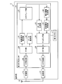
- FIG. 2 is a block diagram showing an example of the base station 2 of the first embodiment.
- the base station 2 shown in FIG. 2 includes an antenna 11, a transmitter 12, a receiver 13, a first memory 14, and a first processor 15.
- the antenna 11 transmits and receives, for example, a wireless signal of a wireless carrier.
- the transmitter 12 is a wireless interface that transmits a wireless signal through the antenna 11.
- the receiving unit 13 is a wireless interface that receives a wireless signal through the antenna 11.
- the first memory 14 is an area that includes, for example, a random access memory (RAM) or a read only memory (ROM), and stores various information related to the base station 2.
- RAM random access memory
- ROM read only memory
- the first processor 15 includes, for example, a central processing unit (CPU), a field programmable gate array (FPGA), or a digital signal processor (DSP), and controls the entire base station 2.
- the first processor 15 includes a scheduler unit 21, a data generation unit 22, a power information generation unit 23, and a control signal generation unit 24.
- the first processor 15 further includes a mapping unit 25, an IFFT (Inverse Fast Fourier Transform) unit 26, and a CP (Cyclic Prefix) addition unit 27.
- the first processor 15 further includes a CP removing unit 28, an FFT (Fast Fourier Transform) unit 29, a data decoding unit 30, and a control signal decoding unit 31.
- the scheduler unit 21 executes scheduling for allocating radio resources to data such as eMBB data and URLLC data transmitted and received between the plurality of terminal devices 3. Specifically, the scheduler unit 21 performs uplink scheduling from the terminal device 3 to the base station 2 by allocating radio resources to data such as eMBB data and URLLC data transmitted by each terminal device 3. The scheduler unit 21 also executes downlink scheduling from the base station 2 to the terminal device 3 by assigning radio resources to data such as eMBB data and URLLC data transmitted to each terminal device 3.
- the data generation unit 22 generates data such as eMBB data and URLLC data to be transmitted to the terminal device 3 based on the downlink scheduling information by the scheduler unit 21. That is, the data generation unit 22 encodes and modulates data such as eMBB data and URLLC data addressed to the terminal device 3.
- the power information generation unit 23 generates uplink and downlink transmission power information.
- the control signal generation unit 24 generates control signals such as eMBB and URLLC based on the scheduling information by the scheduler unit 21. Specifically, when a radio resource is allocated to uplink URLLC data, the control signal generation unit 24 generates a URLLC control signal specifying a coding rate, modulation scheme, transmission power, etc. of the URLLC data. .
- This URLLC control signal is transmitted to the terminal device 3 that transmits the URLLC data.
- the control signal generation unit 24 generates an eMBB control signal that specifies the coding rate of eMBB data, modulation scheme, transmission power, and the like for the terminal device 3 that transmits eMBB data.
- the control signal generation unit 24 also generates a downlink control signal indicating a coding rate of data such as eMBB data and URLLC data to be transmitted to each terminal device 3, modulation scheme, transmission power, and the like.
- the mapping unit 25 maps eMBB data, URLLC data, and control signals, for example, to generate a transmission signal.
- the mapping unit 25 arranges, for example, the eMBB data, the URLLC data, and the control signal in the radio resource based on the scheduling information. For example, the mapping unit 25 further divides each slot constituting the transmission signal into a plurality of minislots, and performs mapping on a minislot basis. As a result, when radio resources are allocated to uplink URLLC data, the mapping unit 25 maps the URLLC control signal to the minislot.
- the IFFT unit 26 performs inverse fast Fourier transform on the transmission signal generated by the mapping unit 25 to convert the transmission signal in the frequency domain into a transmission signal in the time domain. Then, the IFFT unit 26 outputs the transmission signal to the CP addition unit 27.
- the CP adding unit 27 adds a CP to the transmission signal output from the IFFT unit 26 in symbol units. Then, the CP addition unit 27 outputs the transmission signal to which the CP is added to the transmission unit 12.
- the CP removing unit 28 removes the CP added to the reception signal from the receiving unit 13 in symbol units. Then, CP removing section 28 outputs the received signal after CP removal to FFT section 29.
- the FFT unit 29 performs fast Fourier transform on the received signal output from the CP removing unit 28 and converts the received signal in the time domain into a received signal in the frequency domain.
- the received signal includes eMBB data and URLLC data transmitted from each terminal device 3.
- the data decoding unit 30 demodulates and decodes data such as eMBB data and URLLC data included in the received signal.
- data decoding unit 30 decodes the entire eMBB data on the assumption that eMBB data to be received in the next slot is present at the position of the URLLC data, for example.
- the control signal decoding unit 31 When the control signal decoding unit 31 detects a request for URLLC data from the terminal device 3, the control signal decoding unit 31 instructs the scheduler unit 21 to assign a radio resource to the uplink URLLC data.
- the transmission unit 12 performs wireless transmission processing such as D / A (Digital / Analog) conversion and up-conversion on the transmission signal output from the CP addition unit 27.
- the transmitter 12 also transmits a transmission signal via the antenna 11.
- the receiving unit 13 receives a wireless signal via the antenna 11, and performs wireless reception processing such as down conversion and A / D (Analog / Digital) conversion on the received signal. Then, the receiving unit 13 outputs the received signal to the CP removing unit 28.
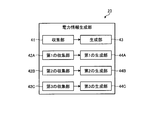
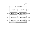
- FIG. 3 is a block diagram illustrating an example of the power information generation unit 23 according to the first embodiment.
- the power information generation unit 23 illustrated in FIG. 3 includes a collection unit 41, a first collection unit 42A, a second collection unit 42B, a third collection unit 42C, a generation unit 43, and a first generation unit. It has 44A, the 2nd generation part 44B, and the 3rd generation part 44C.
- Equation 1 is, for example, an equation for calculating the uplink transmission power amount P PUSCH on the side of the terminal device 3 of the subframe i of the cell c.
- P CMAX is the allowable maximum amount of transmission power available for the uplink in the terminal apparatus 3
- M PUSCH is the number of resource blocks
- P o _ PUSCH is the target received power.
- ⁇ is a path loss compensation coefficient
- PL is a measured value of path loss between the cell and the terminal device 3
- ⁇ TF is a power offset value induced by MCS
- f is “short fading on uplink” And so on according to the amount of fading.
- the terminal device 3 calculates the uplink transmission power amount for the base station 2 based on (Equation 1). However, when the base station 2 is an NR cell, the terminal device 3 can not accurately calculate the uplink transmission power amount for the base station 2 reflecting the carrier of the NR cell. Therefore, the terminal device 3 calculates the amount of uplink transmission power for the base station 2 of the NR cell based on (Equation 2). As a result, even in the case of the base station 2 of the NR cell, the terminal device 3 can calculate the uplink transmission power amount reflecting the carrier of the NR cell with high accuracy.
- ⁇ B is, for example, a first correction amount that corrects “P CMAX ” in ( Expression 1) according to the signal waveform of the carrier of the NR cell.
- the signal waveform of the carrier of the NR cell is different in PAPR (Peak to Average Power Ratio), such as CP-OFDM (Orthogonal frequency division multiplexing) or DFT (Discrete Fourier Transform) -S (Spread) -OFDM.
- the first correction amount is, for example, a correction amount for avoiding signal distortion of the output amplifier caused by the carrier type of the NR cell.
- ⁇ SCS is, for example, a second correction amount for correcting the calculated power amount Pc in accordance with the TTI (Transmission Time Interval) of the carrier of the NR cell.
- the radio parameters (numerology) of the carriers of the NR cell are, for example, different in TTI.
- the second correction amount is a correction amount for compensating for a power density change that changes when TTI is different in different NR carriers.
- “f” is also a third correction amount for correcting the calculated power amount Pc according to the uplink fading amount.
- the calculated power amount Pc is calculated using a parameter set when wireless communication is established between the base station 2 and the terminal device 3 as shown in (Equation 3).
- the parameters are, for example, “M PUSCH ,” “P o _P USCH ,” “ ⁇ ,” “PL,” “ ⁇ TF, ” etc.
- the collection unit 41 collects parameters such as “M PUSCH ”, “P o _P USCH ”, “ ⁇ ”, “PL” and “ ⁇ TF ” used in (Equation 2).
- the first collection unit 42A collects various parameters related to the first correction amount " ⁇ B ".
- the second collection unit 42B collects various parameters related to the second correction amount “ ⁇ SCS ”.
- the third collection unit 42C collects various parameters related to the third correction amount "f”.
- the generation unit 43 generates the parameters collected by the collection unit 41.
- the first generation unit 44A generates a first correction amount " ⁇ B " using various parameters collected by the first collection unit 42A.
- the second generation unit 44B generates a second correction amount “ ⁇ SCS ” with the various parameters collected by the second collection unit 42B.
- the third generation unit 44C generates a third correction amount "f” using various parameters collected by the third collection unit 42C.
- the control signal generation unit 24 generates a control signal of RRC (Radio Resource Control) signaling information including the parameter generated by the generation unit 43.
- the RRC signaling information including the parameter is notified from the base station 2 to the terminal device 3 when the wireless communication between the terminal device 3 and the base station 2 is established.
- the control signal generation unit 24 generates a control signal of a TPC (Transmission Power Control) command of L1 signaling information including the first correction amount, the second correction amount, and the third correction amount.
- the TPC command of the L1 signaling information including the first correction amount, the second correction amount, and the third correction amount is notified from the base station 2 to the terminal device 3 at a predetermined timing.
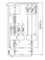
- FIG. 4 is a block diagram showing an example of the terminal device 3 of the first embodiment.
- the terminal device 3 illustrated in FIG. 4 includes an antenna 51, a transmitting unit 52, a receiving unit 53, a second memory 54, and a second processor 55.
- the antenna 51 transmits and receives, for example, a radio signal to and from the terminal device 3.
- the transmission unit 52 is a wireless interface that transmits a wireless signal through the antenna 51.
- the receiving unit 53 is a wireless interface that receives a wireless signal through the antenna 51.
- the second memory 54 is an area that includes, for example, a random access memory (RAM) or a read only memory (ROM), and stores various information related to the terminal device 3.
- the second processor 55 includes, for example, a central processing unit (CPU), a field programmable gate array (FPGA), a digital signal processor (DSP), and the like, and controls the entire terminal device 3.
- CPU central processing unit
- FPGA field programmable gate array
- DSP digital signal processor
- the receiving unit 53 receives a wireless signal via the antenna 51, and performs wireless reception processing such as down conversion and A / D conversion on the received signal. Then, the reception unit 53 outputs the reception signal to the second processor 55. In addition, the transmission unit 52 performs wireless transmission processing such as D / A conversion and up-conversion on the transmission signal output from the second processor 55. Then, the transmission unit 52 transmits a transmission signal via the antenna 51.
- the second processor 55 includes a CP removal unit 61, an FFT unit 62, a CA (Carrier Aggregation) / DC (Dual Connectivity) control unit 63, an eMBB data decoding unit 64, and a URLLC data decoding unit 65. Furthermore, the second processor 55 includes a control signal decoding unit 66, a transmission power control unit 67, a scheduler unit 68, an eMBB data generation unit 69, a URL LC data generation unit 70, a control signal generation unit 71, and an IFFT. A unit 72 and a CP addition unit 73 are provided.
- the CP removal unit 61 removes the CP added to the received signal in symbol units. Then, CP removing section 61 outputs the received signal after CP removal to FFT section 62.
- the FFT unit 62 fast Fourier transforms the received signal output from the CP removing unit 61, and converts the received signal in the time domain into a received signal in the frequency domain.
- the received signal includes, for example, eMBB data, URLLC data, control signals, etc. transmitted from the base station 2.
- the eMBB data decoding unit 64 demodulates and decodes eMBB data from the received signal in the frequency domain after conversion by the FFT unit 62.
- the URLLC data decoding unit 65 demodulates and decodes URLLC data from the received signal in the frequency domain after conversion by the FFT unit 62.
- the control signal decoding unit 66 demodulates and decodes the control signal included in the received signal.
- the eMBB data generation unit 69 generates eMBB data to be transmitted to the base station 2, and encodes and modulates the generated eMBB data. In addition, the eMBB data generation unit 69 generates data to be transmitted to the base station 2, and encodes and modulates the generated data. Then, the eMBB data generation unit 69 outputs the modulated eMBB data to the IFFT unit 72.
- the IFFT unit 72 performs inverse fast Fourier transform on the eMBB data output from the eMBB data generation unit 69 to convert the transmission signal in the frequency domain into a transmission signal in the time domain. Then, the IFFT unit 72 outputs the transmission signal in the time domain to the CP addition unit 73.
- the CP adding unit 73 adds a CP to the transmission signal output from the IFFT unit 72 in units of symbols. Then, the CP addition unit 73 outputs the transmission signal to which the CP is added to the transmission unit 52.
- the CA / DC control unit 63 controls the CA based on the control signal, and outputs the CA control result to the scheduler unit 68. Further, the CA / DC control unit 63 controls DC based on the control signal, and outputs a DC control result to the scheduler unit 68.
- the transmission power control unit 67 determines a parameter in RRC signaling information, a first correction amount in the TCP command in L1 signaling information, a second correction amount, and a third correction amount, (Equation 2).
- the transmission power amount of the uplink to the base station 2 is calculated based on a predetermined function of Then, based on the calculated amount of transmission power, the transmission power control unit 67 controls the transmission power of the uplink to the base station 2 reflecting the NR carrier.
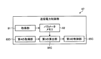
- FIG. 5 is a block diagram illustrating an example of the transmission power control unit 67 according to the first embodiment.
- the transmission power control unit 67 shown in FIG. 5 includes an acquisition unit 81, a parameter memory 82, a first acquisition unit 83A, a second acquisition unit 83B, a third acquisition unit 83C, and a first calculation unit. And a first control unit 85.
- the acquisition unit 81 acquires parameters in the RRC signaling information, and stores the acquired parameters in the parameter memory 82.
- the first acquisition unit 83A acquires a first correction amount in the TPC command.
- the second acquisition unit 83B acquires a second correction amount in the TPC command.
- the third acquisition unit 83C acquires a third correction amount in the TPC command.
- the first calculation unit 84 substitutes the parameter stored in the parameter memory 82, the first correction amount, the second correction amount, and the third correction amount into Equation (4).
- the first calculator 86 calculates the uplink transmission power amount for the base station 2 based on (Equation 4). That is, the first calculation unit 84 calculates the calculated power amount Pc, and corrects the calculated power amount Pc with the second correction amount and the third correction amount. Furthermore, the first calculation unit 84 corrects the allowable maximum transmission power amount with the first correction amount. Then, the first calculation unit 84 sets one of the maximum allowable transmission power after correction by the first correction amount and the calculated power amount Pc after correction by the second correction amount and the third correction amount to be smaller. The amount of power of the other is calculated as the amount of transmission power of the uplink. Then, the first calculation unit 84 sets the calculated transmission power amount in the first control unit 85. The first control unit 85 controls the transmission power of the uplink to the base station 2 based on the calculated transmission power amount.
- the allowable maximum transmission power amount “P CMAX ” is corrected with the first correction amount “ ⁇ B ” that fluctuates according to the signal waveform of the NR carrier.
- the calculated power amount Pc is corrected with the second correction amount “ ⁇ SCS ” that fluctuates according to the TTI of the NR carrier.
- the terminal device 3 corrects the calculated power amount Pc with the third correction amount “f” that fluctuates according to the fading amount.
- the terminal device 3 calculates the transmission power amount of the uplink with respect to the base station 2 based on (Equation 4). As a result, it is possible to calculate the amount of uplink transmission power for the base station 2 reflected in the NR carrier.
- the base station 2 collects the parameter, the first correction amount, the second correction amount, and the third correction amount, and collects the collected parameters, the first correction amount, the first correction amount, The terminal device 3 was notified of the correction amount of 2 and the third correction amount. Then, the terminal device 3 calculates the uplink transmission power amount for the base station 2 based on the parameter, the first correction amount, the second correction amount, the third correction amount, and the predetermined function. However, based on the collected parameters, the first correction amount, the second correction amount, and the third correction amount, the base station 2 calculates the transmission power amount of uplink for the terminal device 3 and calculates the transmission power amount. It may be notified to the terminal device 3 and can be changed as appropriate.
- the terminal device 3 calculates the uplink transmission power amount using the first correction amount, the second correction amount, and the third correction amount.
- the present invention is not limited to these correction amounts, and can be changed as appropriate.
- NR needs to consider SINR (Signal to Interference Noise Ratio).
- SINR Signal to Interference Noise Ratio
- a correction amount for correcting the target received power parameter “P o — PUSCH ” and the path loss compensation coefficient “ ⁇ ” in equation (2) is required according to SINR.
- NR needs to consider beam, signal waveform and service type.
- a correction amount for correcting “P CMAX ⁇ B ” and “ ⁇ SCS + ⁇ TF ” in equation (2) is required according to the service type and the capability of the terminal device 3. Therefore, the terminal device 3 can calculate the uplink transmission power amount reflecting the NR carrier using these correction amounts.
- the terminal device 3 of the first embodiment even when a new carrier is introduced, it is possible to smoothly set the uplink transmission power amount for the base station 2 of the new carrier.
- the terminal device 3 of the first embodiment exemplifies the case of a single carrier, it is also possible to cope with, for example, the case of executing CA (Carrier Aggregation) in which two carriers simultaneously communicate, and the implementation thereof
- CA Carrier Aggregation
- the second embodiment is described below as the second embodiment.
- CA Carrier Aggregation
- different Numerology subcarrier spacing and TTI
- FIG. 6 is an explanatory diagram of an example of the wireless communication system 1A of the second embodiment.
- the same components as those of the wireless communication system 1 according to the first embodiment are denoted by the same reference numerals, and the description of the same components and operations will be omitted.
- a wireless communication system 1A illustrated in FIG. 6 includes a first base station 2A and a terminal device 3.
- the first base station 2A is, for example, identical to the configuration of the base station 2 shown in FIG.
- the terminal device 3 performs simultaneous communication with the first base station 2A using two carriers.
- FIG. 7 is a block diagram showing an example of the power information generation unit 23 of the second embodiment.
- the power information generation unit 23 illustrated in FIG. 7 includes a fourth collection unit 42D instead of the third collection unit 42C, and a fourth generation unit 44D instead of the third generation unit 44C.
- the fourth collection unit 42D is a parameter related to the third correction amount f c1 of the carrier 1 and, collecting the third correction amount f c2 of the carrier 2.
- the control signal generation unit 24 notifies the terminal device 3 of the fourth correction amount with a TPC command of L1 signaling.
- FIG. 8 is an explanatory diagram of an example of the transmission power control unit 67 according to the second embodiment.
- the transmission power control unit 67 shown in FIG. 8 is a fourth acquisition unit 83D in place of the third acquisition unit 83C, a second calculation unit 84B in place of the first calculation unit 84, and a first control unit 85. Instead, it has a second control unit 85B.
- the fourth acquisition unit 83D acquires a fourth correction amount in the TPC command.
- the second calculation unit 84B substitutes the parameter, the first correction amount, the second correction amount, and the fourth correction amount into the equations shown in (Equation 5) and (Equation 3).
- P 1 ” in (Equation 5) is the sum of the calculated power amount Pc of the first base station 2A and the third correction amount corresponding to the carrier 1, as shown in (Equation 6).
- P 2 ” in (Equation 5) is the sum of the calculated power amount Pc of the second base station 2 B and the third correction amount corresponding to the carrier 2 as shown in (Equation 7).
- the fourth correction amount “ ⁇ f” can be expressed by (Equation 8), and the total amount of transmission power “P CM ” of the carrier 1 and the carrier 2 can be expressed by (Equation 9).
- the second calculator 84B calculates uplink transmission power amounts for the carrier 1 and the carrier 2 based on (Equation 5), and sets the calculated transmission power amount in the second controller 85B.
- the second control unit 85B controls uplink transmission power with respect to carrier 1 and carrier 2 based on the calculated transmission power amount.
- the terminal device 3 corrects the allowable maximum transmission power amount “P CMAX ” with the first correction amount “ ⁇ B ” that fluctuates according to the signal waveform of the NR carrier, as shown in ( Equation 5)
- the calculated power amount Pc is corrected with the second correction amount “ ⁇ SCS ” that fluctuates according to the TTI of the carrier.
- the terminal device 3 calculates the uplink transmission power amount for the carrier 1 and the carrier 2 of the first base station 2A based on (Equation 5). As a result, it is possible to calculate the uplink transmission power amount for the two NR carriers.
- the first base station 2A is assumed to be a base station of an NR cell. However, since the first base station 2A is a base station of an LTE cell, the same applies.
- the embodiment will be described below as a third embodiment.
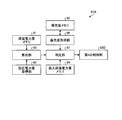
- FIG. 9 is a block diagram of an example of the power information generation unit 23 according to the third embodiment.
- the first base station 2A is a base station of an LTE cell
- the first correction amount and the second correction amount become unnecessary.
- the power information generation unit 23 shown in FIG. 9 does not require the first correction amount and the second correction amount, and thus the first collection unit 42A, the second collection unit 42B, the first generation unit 44A, and the first generation unit 44A.
- the second generation unit 44B is deleted.
- the power information generation unit 23 generates a parameter in the generation unit 43 and generates a fourth correction amount in the fourth generation unit 44D.
- FIG. 10 is a block diagram of an example of the transmission power control unit 67 according to the third embodiment.
- the transmission power control unit 67 illustrated in FIG. 10 eliminates the first acquisition unit 83A and the second acquisition unit 83B because the first correction amount and the second correction amount become unnecessary.
- the transmission power control unit 67 has a third calculation unit 84C instead of the second calculation unit 84B and a third control unit 85C instead of the second control unit 85B.
- the third calculating unit 84C calculates the parameters in the parameter memory 82 and the fourth correction amount acquired by the fourth acquiring unit 83D by the equations (10), (6), (7) and (11). Assign to the formula shown in.
- the third calculator 84C calculates the amount of uplink transmission power for the carrier 1 and carrier 2 of the first base station 2A based on (Equation 10) and (Equation 11), and calculates the calculated transmission power It sets to 3 control part 85C.
- the third control unit 85C controls uplink transmission power for the carrier 1 and the carrier 2 of the first base station 2A based on the calculated transmission power amount.
- the terminal device 3 calculates the amount of uplink transmission power for the carrier 1 and the carrier 2 of the first base station 2A based on (Expression 6) to (Expression 9) and (Expression 11).
- the first base station 2A is an LTE cell, it is possible to calculate uplink transmission power for carrier 1 and carrier 2 of the first base station 2A. That is, instead of transmitting two power control equations simultaneously, only one equation (Equation 11) applicable to both carriers is used. Therefore, since the first base station 2A notifies only the fourth correction amount to the terminal device 3, the signaling overhead can be reduced.
- the case of simultaneously communicating with two carriers of the NR cell of the first base station 2A is exemplified.
- the case of simultaneously communicating with two carriers of the LTE cell of the first base station 2A is illustrated.
- the number of carriers is not limited to two. For example, three or more carriers may be used, and can be appropriately changed.
- FIG. 11 is an explanatory diagram of an example of a wireless communication system 1D of the fourth embodiment.
- the same components as those of the wireless communication system 1 according to the first embodiment are denoted by the same reference numerals, and the description of the same components and operations will be omitted.
- a wireless communication system 1D illustrated in FIG. 11 includes an MCG, an SCG, and a terminal device 3A.
- the MCG is, for example, a cell group of LTE and has a third base station 2C.
- the SCG is, for example, a cell group of NR, and has a fourth base station 2D.
- the third base station 2C and the fourth base station 2D have substantially the same configuration as the base station 2 shown in FIG.
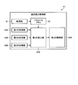
- FIG. 12 is a block diagram showing an example of the terminal device 3A of the fourth embodiment.
- the terminal device 3A illustrated in FIG. 12 includes a transmission power control unit 67A instead of the transmission power control unit 67.
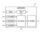
- FIG. 13 is a block diagram showing an example of the transmission power control unit 67A of the fourth embodiment.
- Transmission power control unit 67A shown in FIG. 13 includes guaranteed power amount memory 91, current power amount acquisition unit 92, calculation unit 93, maximum transmission power amount memory 94, priority memory 95, priority acquisition unit 96. , A determination unit 97, and a fourth control unit 85D.
- the guaranteed power amount memory 91 stores MCG's guaranteed power amount (MGP: Maximum Guaranteed Power) and SCG's guaranteed power amount.
- MCG guaranteed power amount is a transmission power amount in which the third base station 2C guarantees the terminal device 3A the minimum transmission power to the uplink of the MCG.
- the guaranteed power amount of SCG is a transmission power amount of which the fourth base station 2D guarantees the terminal device 3A the minimum transmission power for uplink of the SCG. Note that these guaranteed power amounts are to be notified from the base station 2 to the terminal device 3A, for example, by RRC signaling with a period of 10 ms.
- the current power acquisition unit 92 acquires the current power of the MCG and the current power of the SCG.
- the current power amount of MCG is a transmission power amount used by the terminal device 3A in uplink radio communication with the MCG.
- the terminal device 3A calculates the current power amount of the MCG, for example, according to (Equation 1).
- the current amount of power of SCG is the amount of transmission power used by the terminal device 3A in uplink radio communication for SCG. Note that the terminal device 3A calculates the current power amount of SCG, for example, according to (Equation 2).
- the calculation unit 93 calculates the surplus amount of MCG by subtracting the current power amount of MCG from the guaranteed power amount of MCG.
- the excess amount of MCG is the amount of transmission power that can be allocated to another cell group, for example, SCG.
- the surplus amount calculation unit 93 calculates the surplus amount of SCG by subtracting the current power amount of SCG from the guaranteed power amount of SCG.
- the surplus amount of SCG is the amount of transmission power that can be allocated to another cell group, for example, MCG.
- the priority memory 95 is an area for storing the priority for each data type.
- the URLLC data is set to have a higher priority than the eMBB data.
- the priority acquisition unit 96 acquires the priority of the data from the priority memory 95 according to the data type of data used in each slot of the uplink of the SCG.
- the priority acquisition unit 96 acquires the priority of the data from the priority memory 95 according to the data type of data used in each slot of the uplink of the MCG.
- the maximum transmission power amount memory 94 is an area for storing the allowable maximum transmission power amount that can be used by the MCG and SCG in the terminal device 3A.
- the determination unit 97 determines the surplus between MCG and SCG based on the priority of data to be transmitted of MCG and SCG, the allowable maximum transmission power, the first surplus of MCG, and the second surplus of SCG. It is determined whether or not can be assigned to another cell group.
- the timing for determining the allocation of the surplus amount is, for example, started in response to approval of the cell group (grant).
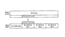
- the terminal device 3A sets data transmitted in minislot B + 1 of SCG as URLLC data, and data transmitted in slot A of MCG as eMBB data. Then, if there is a first surplus in the range of the allowable maximum transmission power in the transmission power of the slot A of the MCG at the timing of the mini slot B + 1 of the SCG, the first surplus of the MCG Allocate to the amount of transmission power of The fourth control unit 85D adds the first surplus amount of MCG to the transmission power amount of mini slot B + 1 of SCG. As a result, a large amount of transmission power can be secured for the URLLC data at the timing of mini slot B + 1 of MCG, and stable transmission power can be secured.
- FIG. 14 is an explanatory drawing showing an example of the relationship between the transmission power amount of the slot of the LTE cell group and the transmission power amount of the slot of the NR cell group.
- eMBB data is used in slot A of an LTE cell group of MCG and URLLC data is used in minislot B + 1 of an NR cell group of SCG.
- the determination unit 97 determines that the first surplus in the range of the allowable maximum transmission power exists in the transmission power of the slot A of the LTE cell group at the timing of mini slot B + 1 of the NR cell group.
- the fourth control unit 85D allocates the first surplus amount of the slots of the LTE cell group at the timing of the mini slot B + 1 of the NR cell group to the transmission power amount of the mini slot B + 1.
- FIG. 15 is an explanatory drawing showing an example of the relationship between the transmission power amount of the slot of the LTE cell group and the transmission power amount of the slot of the NR cell group.
- the terminal device 3A detects a request for transmission of URLLC data in minislot B + 1 of the NR cell group while allocating the second surplus from slot of the NR cell group to slot A of the LTE cell group.
- the determination unit 97 determines that the first surplus in the range of the allowable maximum transmission power exists in the transmission power of the slot A of the LTE cell group at the timing of minislot B + 1 of the NR cell group.
- the fourth control unit 85D allocates the second surplus of the slots of the LTE cell group at the timing of the mini slot B + 1 of the NR cell group to the transmission power of the mini slot B + 1.
- the terminal device 3A reduces the amount of transmission power of the slots of the LTE cell group at the timing of minislot B + 1.
- the terminal device 3A can stably output the URLLC data in minislot B + 1 in order to allocate the first surplus amount obtained by reduction to the transmission power amount in minislot B + 1 and increase the transmission power amount.
- the priority is set higher for the URLLC data than the eMBB data
- the present invention is not limited to two data types, and the priority is set among three or more data types. It may be changed as appropriate.
- the type of data is illustrated as the priority, for example, it may be identified by the type of channel, the type of traffic, UCI (Uplink Control Information), etc., and can be changed as appropriate.
- the radio communication system 1D in which the MCG is an LTE cell group and the SCG is an NR cell group is illustrated, but the radio communication system may be appropriately changed in which the MCG is an NR cell group and the SCG is an LTE cell group.
- MCG and SCG may be a wireless communication system of NR cell group.
Priority Applications (6)
| Application Number | Priority Date | Filing Date | Title |
|---|---|---|---|
| EP17921218.8A EP3668193B1 (en) | 2017-08-10 | 2017-08-10 | Terminal device, base station device, wireless communication system and wireless communication method |
| PCT/JP2017/029146 WO2019030904A1 (ja) | 2017-08-10 | 2017-08-10 | 端末装置、基地局装置、無線通信システム及び無線通信方法 |
| KR1020197012196A KR102263629B1 (ko) | 2017-08-10 | 2017-08-10 | 단말 장치, 기지국 장치, 무선 통신 시스템 및 무선 통신 방법 |
| JP2018568996A JPWO2019030904A1 (ja) | 2017-08-10 | 2017-08-10 | 端末装置、基地局装置、無線通信システム及び無線通信方法 |
| CN201780067320.0A CN109891949B (zh) | 2017-08-10 | 2017-08-10 | 终端装置和无线电基站装置 |
| US16/366,525 US10772047B2 (en) | 2017-08-10 | 2019-03-27 | Transmission power sharing between dual connectivity cell groups |
Applications Claiming Priority (1)
| Application Number | Priority Date | Filing Date | Title |
|---|---|---|---|
| PCT/JP2017/029146 WO2019030904A1 (ja) | 2017-08-10 | 2017-08-10 | 端末装置、基地局装置、無線通信システム及び無線通信方法 |
Related Child Applications (1)
| Application Number | Title | Priority Date | Filing Date |
|---|---|---|---|
| US16/366,525 Continuation US10772047B2 (en) | 2017-08-10 | 2019-03-27 | Transmission power sharing between dual connectivity cell groups |
Publications (1)
| Publication Number | Publication Date |
|---|---|
| WO2019030904A1 true WO2019030904A1 (ja) | 2019-02-14 |
Family
ID=65271940
Family Applications (1)
| Application Number | Title | Priority Date | Filing Date |
|---|---|---|---|
| PCT/JP2017/029146 WO2019030904A1 (ja) | 2017-08-10 | 2017-08-10 | 端末装置、基地局装置、無線通信システム及び無線通信方法 |
Country Status (6)
| Country | Link |
|---|---|
| US (1) | US10772047B2 (ko) |
| EP (1) | EP3668193B1 (ko) |
| JP (1) | JPWO2019030904A1 (ko) |
| KR (1) | KR102263629B1 (ko) |
| CN (1) | CN109891949B (ko) |
| WO (1) | WO2019030904A1 (ko) |
Cited By (2)
| Publication number | Priority date | Publication date | Assignee | Title |
|---|---|---|---|---|
| WO2020225695A1 (en) * | 2019-05-03 | 2020-11-12 | Lenovo (Singapore) Pte. Ltd. | Method and apparatus for verification of dual carrier dynamic power sharing |
| JP7460848B2 (ja) | 2020-07-24 | 2024-04-02 | 維沃移動通信有限公司 | 電力取得方法、装置及びノード機器 |
Families Citing this family (8)
| Publication number | Priority date | Publication date | Assignee | Title |
|---|---|---|---|---|
| CN111492698A (zh) * | 2017-11-09 | 2020-08-04 | 株式会社Ntt都科摩 | 用户终端以及无线通信方法 |
| BR112020019927A2 (pt) * | 2018-03-30 | 2021-01-05 | Guangdong Oppo Mobile Telecommunications Corp., Ltd. | Método e dispositivo para transmitir informações de controle de enlace ascendente |
| US11490434B2 (en) | 2018-06-25 | 2022-11-01 | Qualcomm Incorporated | Dual connectivity transmission techniques |
| US11356962B2 (en) * | 2019-01-07 | 2022-06-07 | Qualcomm Incorporated | Power control in NR-NR dual connectivity |
| US11589403B2 (en) * | 2019-02-25 | 2023-02-21 | Qualcomm Incorporated | Uplink power control prioritization in dual connectivity |
| CN111642001B (zh) * | 2019-03-01 | 2023-11-21 | 中兴通讯股份有限公司 | 信道或信号的发送方法及装置、存储介质 |
| US11284359B2 (en) * | 2019-03-29 | 2022-03-22 | Mediatek Inc. | Uplink power control and time-division multiplexing patterns for dual active protocol stack based handover |
| KR20210015562A (ko) * | 2019-08-02 | 2021-02-10 | 삼성전자주식회사 | 무선 통신 시스템에서 전력 제어를 위한 장치 및 방법 |
Citations (4)
| Publication number | Priority date | Publication date | Assignee | Title |
|---|---|---|---|---|
| JP2010050936A (ja) * | 2008-08-25 | 2010-03-04 | Ntt Docomo Inc | ユーザ装置及び基地局装置並びに通信制御方法 |
| JP2013255278A (ja) * | 2010-04-30 | 2013-12-19 | Panasonic Corp | 基地局装置、通信方法及び集積回路 |
| WO2016002393A1 (ja) * | 2014-06-30 | 2016-01-07 | 株式会社Nttドコモ | ユーザ端末、無線基地局、無線通信システムおよび無線通信方法 |
| JP2016195413A (ja) * | 2016-06-20 | 2016-11-17 | 株式会社Nttドコモ | ユーザ端末、無線基地局及び無線通信方法 |
Family Cites Families (13)
| Publication number | Priority date | Publication date | Assignee | Title |
|---|---|---|---|---|
| US8744513B2 (en) * | 2010-06-29 | 2014-06-03 | Qualcomm Incorporated | Interaction between maximum power reduction and power scaling in wireless networks |
| CN104349443B (zh) * | 2013-08-09 | 2019-02-12 | 电信科学技术研究院 | 一种上行功率控制方法和装置 |
| KR102184585B1 (ko) * | 2014-03-21 | 2020-11-30 | 후아웨이 테크놀러지 컴퍼니 리미티드 | 이중 연결을 고려한 전력 제한 상황에서의 pusch/pucch 전력 스케일링 방법 및 그 장치 |
| US20150327243A1 (en) * | 2014-05-08 | 2015-11-12 | Sharp Laboratories Of America, Inc. | Systems and methods for dual-connectivity operation |
| JP6523278B2 (ja) * | 2014-06-20 | 2019-05-29 | シャープ株式会社 | 端末装置、基地局装置、および通信方法 |
| US20160021618A1 (en) * | 2014-07-18 | 2016-01-21 | Sharp Laboratories Of America, Inc. | Systems and methods for uplink transmission power control |
| WO2016053174A1 (en) * | 2014-09-29 | 2016-04-07 | Telefonaktiebolaget L M Ericsson (Publ) | Indication to the master e-node b of successful primary secondary cell activation in dual connectivity |
| CN105873213B (zh) * | 2015-01-20 | 2019-11-19 | 电信科学技术研究院 | 一种进行上行调度的方法和设备 |
| JP6612554B2 (ja) * | 2015-08-24 | 2019-11-27 | 株式会社Nttドコモ | 無線基地局、ユーザ端末、無線通信方法 |
| JP6174200B2 (ja) * | 2016-06-06 | 2017-08-02 | 株式会社Nttドコモ | ユーザ端末、無線基地局及び無線通信方法 |
| US10448386B2 (en) * | 2017-01-06 | 2019-10-15 | Kt Corporation | Method and apparatus for controlling redundant data transmission |
| KR102016728B1 (ko) * | 2017-01-06 | 2019-09-02 | 주식회사 케이티 | 데이터 중복 전송을 제어하는 방법 및 그 장치 |
| WO2019070091A1 (ko) * | 2017-10-02 | 2019-04-11 | 엘지전자 주식회사 | Lte와 nr간의 이중 연결에서 상향링크를 전송하는 방법 및 사용자 장치 |
-
2017
- 2017-08-10 CN CN201780067320.0A patent/CN109891949B/zh active Active
- 2017-08-10 KR KR1020197012196A patent/KR102263629B1/ko active IP Right Grant
- 2017-08-10 JP JP2018568996A patent/JPWO2019030904A1/ja active Pending
- 2017-08-10 EP EP17921218.8A patent/EP3668193B1/en active Active
- 2017-08-10 WO PCT/JP2017/029146 patent/WO2019030904A1/ja unknown
-
2019
- 2019-03-27 US US16/366,525 patent/US10772047B2/en active Active
Patent Citations (4)
| Publication number | Priority date | Publication date | Assignee | Title |
|---|---|---|---|---|
| JP2010050936A (ja) * | 2008-08-25 | 2010-03-04 | Ntt Docomo Inc | ユーザ装置及び基地局装置並びに通信制御方法 |
| JP2013255278A (ja) * | 2010-04-30 | 2013-12-19 | Panasonic Corp | 基地局装置、通信方法及び集積回路 |
| WO2016002393A1 (ja) * | 2014-06-30 | 2016-01-07 | 株式会社Nttドコモ | ユーザ端末、無線基地局、無線通信システムおよび無線通信方法 |
| JP2016195413A (ja) * | 2016-06-20 | 2016-11-17 | 株式会社Nttドコモ | ユーザ端末、無線基地局及び無線通信方法 |
Non-Patent Citations (3)
| Title |
|---|
| HUAWEI ET AL.: "Low frequency assisted high frequency operation", 3GPP TSG-RAN WG1#86 R1- 166114, 26 August 2016 (2016-08-26), XP051125219 * |
| NOKIA ET AL.: "UL Interference Coordination and Power Control", 3GPP TSG-RAN WG1#86B R1-1610281, 14 October 2016 (2016-10-14), XP051150298 * |
| See also references of EP3668193A4 * |
Cited By (3)
| Publication number | Priority date | Publication date | Assignee | Title |
|---|---|---|---|---|
| WO2020225695A1 (en) * | 2019-05-03 | 2020-11-12 | Lenovo (Singapore) Pte. Ltd. | Method and apparatus for verification of dual carrier dynamic power sharing |
| US11246103B2 (en) | 2019-05-03 | 2022-02-08 | Lenovo (Singapore) Pte. Ltd. | Method and apparatus for verification of dual carrier dynamic power sharing |
| JP7460848B2 (ja) | 2020-07-24 | 2024-04-02 | 維沃移動通信有限公司 | 電力取得方法、装置及びノード機器 |
Also Published As
| Publication number | Publication date |
|---|---|
| KR102263629B1 (ko) | 2021-06-11 |
| CN109891949B (zh) | 2022-07-26 |
| EP3668193B1 (en) | 2021-08-11 |
| EP3668193A4 (en) | 2020-08-05 |
| EP3668193A1 (en) | 2020-06-17 |
| US10772047B2 (en) | 2020-09-08 |
| CN109891949A (zh) | 2019-06-14 |
| JPWO2019030904A1 (ja) | 2019-11-07 |
| KR20190059944A (ko) | 2019-05-31 |
| US20190223115A1 (en) | 2019-07-18 |
Similar Documents
| Publication | Publication Date | Title |
|---|---|---|
| KR102263629B1 (ko) | 단말 장치, 기지국 장치, 무선 통신 시스템 및 무선 통신 방법 | |
| US11595973B2 (en) | Method for processing uplink control information and terminal | |
| CN108633021B (zh) | 一种上行控制信道的资源映射方法及装置 | |
| CN102783236B (zh) | 无线通信系统、移动站装置、无线通信方法以及集成电路 | |
| KR102616547B1 (ko) | 무선 셀룰라 통신 시스템에서 협대역 신호 전송을 위한 방법 및 장치 | |
| EP3455991B1 (en) | Configuration of downlink transmissions | |
| JP2020522964A (ja) | 無線通信システムにおける資源割当関連シグナリング方法及び上記方法を利用する装置 | |
| KR20180081450A (ko) | 상향링크 제어정보 전송 방법 및 장치 | |
| JP6559903B2 (ja) | 自己完結型エアインターフェースパーティションのためのシステムおよび方法 | |
| EP2870805B1 (en) | Interference control in hetnets | |
| JP6387115B2 (ja) | 無線通信ネットワークにおける通信チャネルへのアクセス | |
| KR102638922B1 (ko) | 무선 셀룰라 통신 시스템에서 다중 타이밍 전송 기술의 송수신 방법 및 장치 | |
| WO2020148122A1 (en) | Communications device, infrastructure equipment and methods | |
| KR20190067498A (ko) | 무선 통신 시스템에서 빔을 이용하여 신호를 송신하기 위한 장치 및 방법 | |
| US20210298044A1 (en) | Communication apparatus, base station apparatus, and communication system | |
| KR20200095879A (ko) | 통신 시스템에서 그랜트 프리 방식에 기초한 상향링크 통신을 위한 방법 및 장치 | |
| CN112995959A (zh) | 基于宽带技术的终端直通通信的信道配置方法 | |
| CN110663281A (zh) | 用于在无线通信系统中为基站终端分配资源的方法以及使用所述方法的通信设备 | |
| US20190182830A1 (en) | Base station apparatus, terminal apparatus, radio communication system, and transmission timing setting method | |
| CN110178391B (zh) | 无线通信方法、终端设备和网络设备 | |
| EP4189884A1 (en) | Communications devices, network infrastructure equipment, wireless communications networks and methods | |
| WO2018173208A1 (ja) | 基地局装置、端末装置、無線通信システム、および無線通信方法 | |
| KR20200067391A (ko) | 데이터 전송 지연 감소를 위한 신호의 송수신 방법 및 장치 | |
| KR20190017596A (ko) | 빔포밍 시스템에서 단말의 송신 전력 제어 방법 및 장치 | |
| KR20210155762A (ko) | 통신 시스템에서 커버리지 확장을 위한 방법 및 장치 |
Legal Events
| Date | Code | Title | Description |
|---|---|---|---|
| ENP | Entry into the national phase |
Ref document number: 2018568996 Country of ref document: JP Kind code of ref document: A |
|
| 121 | Ep: the epo has been informed by wipo that ep was designated in this application |
Ref document number: 17921218 Country of ref document: EP Kind code of ref document: A1 |
|
| ENP | Entry into the national phase |
Ref document number: 20197012196 Country of ref document: KR Kind code of ref document: A |
|
| NENP | Non-entry into the national phase |
Ref country code: DE |
|
| ENP | Entry into the national phase |
Ref document number: 2017921218 Country of ref document: EP Effective date: 20200310 |