WO2019026320A1 - 表示制御装置 - Google Patents
表示制御装置 Download PDFInfo
- Publication number
- WO2019026320A1 WO2019026320A1 PCT/JP2018/006260 JP2018006260W WO2019026320A1 WO 2019026320 A1 WO2019026320 A1 WO 2019026320A1 JP 2018006260 W JP2018006260 W JP 2018006260W WO 2019026320 A1 WO2019026320 A1 WO 2019026320A1
- Authority
- WO
- WIPO (PCT)
- Prior art keywords
- image
- height
- unit
- vehicle
- imaging unit
- Prior art date
Links
- 238000012937 correction Methods 0.000 claims abstract description 37
- 239000011165 3D composite Substances 0.000 claims abstract description 12
- 230000000630 rising effect Effects 0.000 claims abstract description 11
- 238000003384 imaging method Methods 0.000 claims description 139
- 238000001514 detection method Methods 0.000 claims description 6
- 230000002093 peripheral effect Effects 0.000 description 25
- 238000012545 processing Methods 0.000 description 18
- 230000008859 change Effects 0.000 description 6
- 238000005259 measurement Methods 0.000 description 6
- 240000004050 Pentaglottis sempervirens Species 0.000 description 5
- 235000004522 Pentaglottis sempervirens Nutrition 0.000 description 5
- 230000001133 acceleration Effects 0.000 description 4
- 230000000694 effects Effects 0.000 description 4
- 101100064079 Mus musculus Pdss1 gene Proteins 0.000 description 3
- 238000002485 combustion reaction Methods 0.000 description 3
- 238000009434 installation Methods 0.000 description 3
- 230000015572 biosynthetic process Effects 0.000 description 2
- 239000002131 composite material Substances 0.000 description 2
- 238000010586 diagram Methods 0.000 description 2
- 238000006073 displacement reaction Methods 0.000 description 2
- 230000006870 function Effects 0.000 description 2
- 238000004519 manufacturing process Methods 0.000 description 2
- 238000000034 method Methods 0.000 description 2
- 238000002156 mixing Methods 0.000 description 2
- 238000012986 modification Methods 0.000 description 2
- 230000004048 modification Effects 0.000 description 2
- 230000008569 process Effects 0.000 description 2
- 238000003786 synthesis reaction Methods 0.000 description 2
- 230000005540 biological transmission Effects 0.000 description 1
- 239000000446 fuel Substances 0.000 description 1
- 230000006872 improvement Effects 0.000 description 1
- 239000004973 liquid crystal related substance Substances 0.000 description 1
- 239000000203 mixture Substances 0.000 description 1
- 230000003287 optical effect Effects 0.000 description 1
- 230000008439 repair process Effects 0.000 description 1
- 239000011435 rock Substances 0.000 description 1
- 239000007787 solid Substances 0.000 description 1
- 238000006467 substitution reaction Methods 0.000 description 1
- 230000002194 synthesizing effect Effects 0.000 description 1
- 238000002834 transmittance Methods 0.000 description 1
Images


Classifications
-
- G—PHYSICS
- G06—COMPUTING; CALCULATING OR COUNTING
- G06T—IMAGE DATA PROCESSING OR GENERATION, IN GENERAL
- G06T3/00—Geometric image transformation in the plane of the image
- G06T3/40—Scaling the whole image or part thereof
- G06T3/4038—Scaling the whole image or part thereof for image mosaicing, i.e. plane images composed of plane sub-images
-
- B—PERFORMING OPERATIONS; TRANSPORTING
- B60—VEHICLES IN GENERAL
- B60R—VEHICLES, VEHICLE FITTINGS, OR VEHICLE PARTS, NOT OTHERWISE PROVIDED FOR
- B60R1/00—Optical viewing arrangements; Real-time viewing arrangements for drivers or passengers using optical image capturing systems, e.g. cameras or video systems specially adapted for use in or on vehicles
- B60R1/20—Real-time viewing arrangements for drivers or passengers using optical image capturing systems, e.g. cameras or video systems specially adapted for use in or on vehicles
- B60R1/31—Real-time viewing arrangements for drivers or passengers using optical image capturing systems, e.g. cameras or video systems specially adapted for use in or on vehicles providing stereoscopic vision
-
- B—PERFORMING OPERATIONS; TRANSPORTING
- B60—VEHICLES IN GENERAL
- B60R—VEHICLES, VEHICLE FITTINGS, OR VEHICLE PARTS, NOT OTHERWISE PROVIDED FOR
- B60R1/00—Optical viewing arrangements; Real-time viewing arrangements for drivers or passengers using optical image capturing systems, e.g. cameras or video systems specially adapted for use in or on vehicles
- B60R1/20—Real-time viewing arrangements for drivers or passengers using optical image capturing systems, e.g. cameras or video systems specially adapted for use in or on vehicles
- B60R1/22—Real-time viewing arrangements for drivers or passengers using optical image capturing systems, e.g. cameras or video systems specially adapted for use in or on vehicles for viewing an area outside the vehicle, e.g. the exterior of the vehicle
- B60R1/23—Real-time viewing arrangements for drivers or passengers using optical image capturing systems, e.g. cameras or video systems specially adapted for use in or on vehicles for viewing an area outside the vehicle, e.g. the exterior of the vehicle with a predetermined field of view
- B60R1/24—Real-time viewing arrangements for drivers or passengers using optical image capturing systems, e.g. cameras or video systems specially adapted for use in or on vehicles for viewing an area outside the vehicle, e.g. the exterior of the vehicle with a predetermined field of view in front of the vehicle
-
- B—PERFORMING OPERATIONS; TRANSPORTING
- B60—VEHICLES IN GENERAL
- B60R—VEHICLES, VEHICLE FITTINGS, OR VEHICLE PARTS, NOT OTHERWISE PROVIDED FOR
- B60R1/00—Optical viewing arrangements; Real-time viewing arrangements for drivers or passengers using optical image capturing systems, e.g. cameras or video systems specially adapted for use in or on vehicles
- B60R1/20—Real-time viewing arrangements for drivers or passengers using optical image capturing systems, e.g. cameras or video systems specially adapted for use in or on vehicles
- B60R1/22—Real-time viewing arrangements for drivers or passengers using optical image capturing systems, e.g. cameras or video systems specially adapted for use in or on vehicles for viewing an area outside the vehicle, e.g. the exterior of the vehicle
- B60R1/23—Real-time viewing arrangements for drivers or passengers using optical image capturing systems, e.g. cameras or video systems specially adapted for use in or on vehicles for viewing an area outside the vehicle, e.g. the exterior of the vehicle with a predetermined field of view
- B60R1/27—Real-time viewing arrangements for drivers or passengers using optical image capturing systems, e.g. cameras or video systems specially adapted for use in or on vehicles for viewing an area outside the vehicle, e.g. the exterior of the vehicle with a predetermined field of view providing all-round vision, e.g. using omnidirectional cameras
-
- B—PERFORMING OPERATIONS; TRANSPORTING
- B60—VEHICLES IN GENERAL
- B60R—VEHICLES, VEHICLE FITTINGS, OR VEHICLE PARTS, NOT OTHERWISE PROVIDED FOR
- B60R1/00—Optical viewing arrangements; Real-time viewing arrangements for drivers or passengers using optical image capturing systems, e.g. cameras or video systems specially adapted for use in or on vehicles
- B60R1/20—Real-time viewing arrangements for drivers or passengers using optical image capturing systems, e.g. cameras or video systems specially adapted for use in or on vehicles
- B60R1/22—Real-time viewing arrangements for drivers or passengers using optical image capturing systems, e.g. cameras or video systems specially adapted for use in or on vehicles for viewing an area outside the vehicle, e.g. the exterior of the vehicle
- B60R1/28—Real-time viewing arrangements for drivers or passengers using optical image capturing systems, e.g. cameras or video systems specially adapted for use in or on vehicles for viewing an area outside the vehicle, e.g. the exterior of the vehicle with an adjustable field of view
-
- G—PHYSICS
- G06—COMPUTING; CALCULATING OR COUNTING
- G06T—IMAGE DATA PROCESSING OR GENERATION, IN GENERAL
- G06T1/00—General purpose image data processing
- G06T1/0007—Image acquisition
-
- G—PHYSICS
- G06—COMPUTING; CALCULATING OR COUNTING
- G06T—IMAGE DATA PROCESSING OR GENERATION, IN GENERAL
- G06T15/00—3D [Three Dimensional] image rendering
- G06T15/10—Geometric effects
- G06T15/20—Perspective computation
-
- G—PHYSICS
- G06—COMPUTING; CALCULATING OR COUNTING
- G06T—IMAGE DATA PROCESSING OR GENERATION, IN GENERAL
- G06T17/00—Three dimensional [3D] modelling, e.g. data description of 3D objects
-
- G—PHYSICS
- G06—COMPUTING; CALCULATING OR COUNTING
- G06V—IMAGE OR VIDEO RECOGNITION OR UNDERSTANDING
- G06V20/00—Scenes; Scene-specific elements
- G06V20/50—Context or environment of the image
- G06V20/56—Context or environment of the image exterior to a vehicle by using sensors mounted on the vehicle
- G06V20/58—Recognition of moving objects or obstacles, e.g. vehicles or pedestrians; Recognition of traffic objects, e.g. traffic signs, traffic lights or roads
-
- H—ELECTRICITY
- H04—ELECTRIC COMMUNICATION TECHNIQUE
- H04N—PICTORIAL COMMUNICATION, e.g. TELEVISION
- H04N7/00—Television systems
- H04N7/18—Closed-circuit television [CCTV] systems, i.e. systems in which the video signal is not broadcast
- H04N7/188—Capturing isolated or intermittent images triggered by the occurrence of a predetermined event, e.g. an object reaching a predetermined position
-
- B—PERFORMING OPERATIONS; TRANSPORTING
- B60—VEHICLES IN GENERAL
- B60R—VEHICLES, VEHICLE FITTINGS, OR VEHICLE PARTS, NOT OTHERWISE PROVIDED FOR
- B60R2300/00—Details of viewing arrangements using cameras and displays, specially adapted for use in a vehicle
- B60R2300/10—Details of viewing arrangements using cameras and displays, specially adapted for use in a vehicle characterised by the type of camera system used
- B60R2300/105—Details of viewing arrangements using cameras and displays, specially adapted for use in a vehicle characterised by the type of camera system used using multiple cameras
-
- B—PERFORMING OPERATIONS; TRANSPORTING
- B60—VEHICLES IN GENERAL
- B60R—VEHICLES, VEHICLE FITTINGS, OR VEHICLE PARTS, NOT OTHERWISE PROVIDED FOR
- B60R2300/00—Details of viewing arrangements using cameras and displays, specially adapted for use in a vehicle
- B60R2300/60—Details of viewing arrangements using cameras and displays, specially adapted for use in a vehicle characterised by monitoring and displaying vehicle exterior scenes from a transformed perspective
-
- B—PERFORMING OPERATIONS; TRANSPORTING
- B60—VEHICLES IN GENERAL
- B60R—VEHICLES, VEHICLE FITTINGS, OR VEHICLE PARTS, NOT OTHERWISE PROVIDED FOR
- B60R2300/00—Details of viewing arrangements using cameras and displays, specially adapted for use in a vehicle
- B60R2300/80—Details of viewing arrangements using cameras and displays, specially adapted for use in a vehicle characterised by the intended use of the viewing arrangement
- B60R2300/802—Details of viewing arrangements using cameras and displays, specially adapted for use in a vehicle characterised by the intended use of the viewing arrangement for monitoring and displaying vehicle exterior blind spot views
-
- G—PHYSICS
- G06—COMPUTING; CALCULATING OR COUNTING
- G06T—IMAGE DATA PROCESSING OR GENERATION, IN GENERAL
- G06T2207/00—Indexing scheme for image analysis or image enhancement
- G06T2207/30—Subject of image; Context of image processing
- G06T2207/30248—Vehicle exterior or interior
- G06T2207/30252—Vehicle exterior; Vicinity of vehicle
-
- G—PHYSICS
- G06—COMPUTING; CALCULATING OR COUNTING
- G06T—IMAGE DATA PROCESSING OR GENERATION, IN GENERAL
- G06T2215/00—Indexing scheme for image rendering
- G06T2215/16—Using real world measurements to influence rendering
Definitions
- Embodiments of the present invention relate to a display control device.
- the periphery of a vehicle is imaged by a plurality of imaging units provided around the vehicle, and the plurality of imaged image data thus imaged are combined to generate a three-dimensional composite bird's-eye view image for display in a vehicle interior
- an overhead view image generation device that causes the driver to recognize the situation around the vehicle by displaying the image on the device (for example, see Patent Document 1).
- the deviation in the height direction of the composite image caused by the difference in the installation height (the installation ground height) of the imaging unit for imaging each direction (front and rear, left and right of the vehicle) is eliminated.
- the shape in the height direction of a part of the bird's-eye view image (three-dimensional space model) and aligning the position of the horizontal line there is no sense of discomfort in the horizontal line portion of the composite bird's-eye view image displayed I have to.
- the horizontal line of the image to be projected is aligned by changing the shape of part of the three-dimensional space model in the height direction in order to align the horizontal line.
- one of the problems of the present invention is to provide a display control device capable of reducing display deviation of image contents in the height direction without causing unnaturalness in the shape of an edge or the like of a three-dimensional composite image. It is in.
- the display control device is, for example, a first image obtained from a first imaging unit which is provided at a first height position of a vehicle and captures a situation in a first direction among the surroundings of the vehicle; A second image obtained from a second imaging unit provided at a second height position different from the first height position and imaging a situation in a second direction different from the first direction
- a projection surface acquisition unit capable of projecting a first image and a second image, and acquiring a three-dimensional virtual projection surface including at least a side surface rising in the height direction from the ground surface of the vehicle; Based on the difference between the first height position and the second height position, at least one of the first image and the second image to be projected onto the virtual projection plane is a projection position of the first image.
- the virtual projection plane is generated based on the difference between the height positions. Correct the contents of the image to be projected (projected position). In this case, since the shape of the virtual projection plane is not changed, there is no change in the shape of the outer edge portion etc. of the displayed three-dimensional composite image, and the image content in the height direction is not Misalignment can be reduced.
- the correction unit of the display control device of the embodiment may correct the projection position based on, for example, a height ratio between the first height position and the second height position. . According to this configuration, it is possible to more appropriately correct, for example, display displacement caused by the difference between the first height position of the first imaging unit and the second height position of the second imaging unit.
- the display control device further includes, for example, a position detection unit capable of detecting the position of an object present around the vehicle, and the projection plane acquisition unit corresponds to the position corresponding to the position of the object
- the virtual projection plane including the side surface may be acquired.
- FIG. 1 is a perspective view showing an example in which a part of a cabin of a vehicle equipped with a display control apparatus according to the embodiment is seen through.
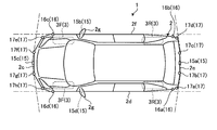
- FIG. 2 is a plan view (bird's-eye view) showing an example of a vehicle equipped with the display control apparatus according to the embodiment.
- FIG. 3 is a block diagram showing an example of the configuration of a display control system having the display control device according to the embodiment.
- FIG. 4 is an exemplary block diagram of a configuration of a CPU of the display control device according to the embodiment.
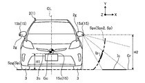
- FIG. 5 is an exemplary and schematic explanatory view showing the projection of a captured image on a virtual projection plane in the display control system according to the embodiment.
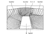
- FIG. 6 is an exemplary and schematic explanatory view showing a virtual projection plane (three-dimensional virtual model) used in the display control apparatus according to the embodiment.
- FIG. 7 is a schematic and exemplary side view showing a vehicle shape model and a virtual projection plane in the display control system according to the embodiment.
- FIG. 8 schematically and exemplarily illustrates the occurrence of display deviation in the height direction of the three-dimensional composite image due to the height position of the imaging unit in the display control device according to the embodiment and correction of the display deviation.
- FIG. FIG. 9 is a view showing a display example of a schematic three-dimensional composite image for explaining the occurrence of display deviation in the height direction of the three-dimensional composite image caused by the height position of the imaging unit.
- FIG. 10 is a schematic three-dimensional composite image in the case where display deviation in the height direction of the three-dimensional composite image caused by the height position of the imaging unit is eliminated by applying the correction by the display control device according to the embodiment; It is a figure which shows the example of a display.
- FIG. 11 is a schematic and exemplary side view of setting the side surface of the virtual projection plane at the detection position of the object in the display control apparatus according to the embodiment.
- the vehicle 1 equipped with a display control device may be, for example, an automobile having an internal combustion engine (not shown) as a drive source, that is, an internal combustion engine automobile or an electric motor (not shown). It may be a car as a drive source, that is, an electric car or a fuel cell car. In addition, it may be a hybrid car using both of them as a driving source, or may be a car equipped with another driving source.
- the vehicle 1 can be mounted with various transmissions, and can be mounted with various devices necessary for driving an internal combustion engine or a motor, such as a system or components.
- a four-wheel drive vehicle can be used which transmits drive power to all four wheels 3 and uses all four wheels as drive wheels.
- the system, number, layout, and the like of the devices involved in the drive of the wheels 3 can be set variously.
- the drive system is not limited to the four-wheel drive system, and may be, for example, a front wheel drive system or a rear wheel drive system.
- the vehicle body 2 constitutes a passenger compartment 2 a in which a passenger (not shown) rides.
- a steering unit 4, an acceleration operation unit 5, a braking operation unit 6, a gear change operation unit 7 and the like are provided in the passenger compartment 2a in a state of facing the driver's seat 2b as a passenger.
- the steering unit 4 is, for example, a steering wheel that protrudes from the dashboard 24.
- the acceleration operation unit 5 is, for example, an accelerator pedal positioned under the driver's foot.
- the brake operation unit 6 is, for example, a brake pedal positioned under the driver's foot
- the shift operation unit 7 is, for example, a shift lever that protrudes from the center console.
- the steering unit 4, the acceleration operation unit 5, the braking operation unit 6, the shift operation unit 7, and the like are not limited to these.
- a display device 8 and an audio output device 9 are provided in the passenger compartment 2a.
- the display device 8 is, for example, a liquid crystal display (LCD), an organic electroluminescent display (OELD), or the like.
- the audio output device 9 is, for example, a speaker.
- the display device 8 is covered with a transparent operation input unit 10 such as a touch panel, for example. The occupant can visually recognize the image displayed on the display screen of the display device 8 through the operation input unit 10.
- an occupant operates the operation input unit 10 by touching or pushing or moving the operation input unit 10 with a finger or the like at a position corresponding to the image displayed on the display screen of the display device 8. It can be done.
- the display device 8, the audio output device 9, the operation input unit 10, and the like are provided, for example, in the monitor device 11 located at the center of the dashboard 24 in the vehicle width direction, that is, in the lateral direction.
- the monitor device 11 can have an operation input unit (not shown) such as a switch, a dial, a joystick, or a push button.
- an audio output device (not shown) can be provided at another position in the vehicle compartment 2a different from the monitor device 11, and audio is output from the audio output device 9 of the monitor device 11 and another audio output device. be able to.
- the monitor device 11 can also be used as, for example, a navigation system or an audio system.
- the vehicle 1 is, for example, a four-wheeled vehicle, and has two left and right front wheels 3F and two left and right rear wheels 3R. All of these four wheels 3 can be configured to be steerable.
- the vehicle 1 has a steering system 13 that steers at least two wheels 3.
- the steering system 13 has an actuator 13a and a torque sensor 13b.
- the steering system 13 is electrically controlled by an ECU 14 (electronic control unit) or the like to operate the actuator 13a.
- the steering system 13 is, for example, an electric power steering system, an SBW (steer by wire) system, or the like.
- the steering system 13 adds torque, that is, assist torque to the steering unit 4 by the actuator 13a to compensate for the steering force, or steers the wheel 3 by the actuator 13a.
- the actuator 13a may steer one wheel 3 or may steer a plurality of wheels 3.
- the torque sensor 13 b detects, for example, a torque that the driver gives to the steering unit 4.
- the vehicle body 2 is provided with, for example, four imaging units 15a to 15d as the plurality of imaging units 15.
- the imaging unit 15 is, for example, a digital camera that incorporates an imaging device such as a charge coupled device (CCD) or a CMOS image sensor (CIS).
- the imaging unit 15 can output moving image data (captured image data) at a predetermined frame rate.
- Each of the imaging units 15 has a wide-angle lens or a fish-eye lens, and can image a range of, for example, 140 ° to 220 ° in the horizontal direction.
- the optical axis of the imaging unit 15 may be set obliquely downward. Therefore, the imaging unit 15 sequentially captures the environment around the outside of the vehicle 1 including the road surface or object on which the vehicle 1 can move (for example, rocks, trees, people, bicycles and vehicles as obstacles), and captures an image Output as image data.
- the imaging unit 15a is located, for example, at the rear end 2e of the vehicle body 2, and is provided on the lower wall of the rear window of the door 2h of the rear hatch.
- the imaging unit 15 b is, for example, located at the right end 2 f of the vehicle body 2 and provided on the right side door mirror 2 g.
- the imaging unit 15c is located, for example, on the front side of the vehicle body 2, that is, on the end 2c on the front side in the front-rear direction of the vehicle, and is provided on a front bumper, a front grill, or the like.
- the imaging unit 15d is, for example, located at the left end 2d of the vehicle body 2, and is provided to the left side door mirror 2g.
- the display control system 100 in addition to the ECU 14, the monitor device 11, the steering system 13, etc., the brake system 18, steering angle sensor 19, accelerator sensor 20, shift A sensor 21, a wheel speed sensor 22 and the like are electrically connected via an in-vehicle network 23 as a telecommunication line.
- the in-vehicle network 23 is configured, for example, as a controller area network (CAN).
- the ECU 14 can control the steering system 13, the brake system 18 and the like by transmitting control signals through the in-vehicle network 23.
- the ECU 14 detects detection results of the torque sensor 13b, the brake sensor 18b, the steering angle sensor 19, the accelerator sensor 20, the shift sensor 21, the wheel speed sensor 22, and operation signals of the operation input unit 10 etc via the in-vehicle network 23. Etc can be received.
- the vehicle body 2 includes, for example, four distance measuring units 16a to 16d and eight distance measuring units 17a to 17h as a plurality of distance measuring units 16 and 17. It is provided.
- the distance measuring units 16 and 17 are, for example, sonars that emit ultrasonic waves and catch the reflected waves.
- the sonar may also be referred to as a sonar sensor or an ultrasonic detector.
- the ECU 14 can measure the presence or absence of an object such as an obstacle located around the vehicle 1 and the distance (position) to the object based on the detection results of the distance measurement units 16 and 17. Therefore, the distance measuring units 16 and 17 function as position detecting units that detect the position of an object present around the vehicle 1.
- the distance measuring unit 17 can be used, for example, to detect an object at a relatively short distance, and the distance measuring unit 16 can be used, for example, to detect an object at a relatively long distance farther than the distance measuring unit 17. Further, the distance measuring unit 17 can be used, for example, for detecting an object in front of and behind the vehicle 1, and the distance measuring unit 16 can be used for detecting an object on the side of the vehicle 1.
- the ECU 14 has, for example, a CPU 14a (central processing unit), a ROM 14b (read only memory), a RAM 14c (random access memory), a display control unit 14d, an audio control unit 14e, an SSD 14f (solid state drive, flash memory) and the like. ing.
- the CPU 14a reads a program stored (installed) in a non-volatile storage device such as the ROM 14b, and executes arithmetic processing according to the program.
- the CPU 14a executes, for example, image processing related to an image displayed on the display device 8. For example, the CPU 14a performs arithmetic processing and image processing on captured image data captured by the imaging unit 15 to generate a three-dimensional peripheral image (for example, an overhead image).
- the CPU 14a can change the viewpoint of the peripheral image to be generated.
- the CPU 14a detects whether or not an object (for example, another vehicle, a wall, an obstacle such as a pedestrian, etc.) to be careful around the vehicle 1 exists, or a peripheral image based on the position of the detected object
- the display mode of can be changed.
- the CPU 14a can also execute a process of notifying the user (driver or passenger) of the presence of the object based on the detected object.
- the RAM 14c temporarily stores various data used in the calculation in the CPU 14a.
- the display control unit 14d mainly performs composition of image data displayed on the display device 8 and the like in the arithmetic processing in the ECU 14.
- the voice control unit 14 e mainly performs processing of voice data output from the voice output device 9 among the calculation processing in the ECU 14.
- the SSD 14 f is a rewritable non-volatile storage unit, and can store data even when the power supply of the ECU 14 is turned off.
- the CPU 14a, the ROM 14b, the RAM 14c, and the like can be integrated in the same package.
- the ECU 14 may be configured to use another logical operation processor such as a DSP (digital signal processor) or a logic circuit instead of the CPU 14a.
- a hard disk drive (HDD) may be provided instead of the SSD 14f, and the SSD 14f and the HDD may be provided separately from the ECU 14.
- the brake system 18 enhances, for example, an anti-lock brake system (ABS) that suppresses the lock of the brake, an anti-slip device (ESC: electronic stability control) that suppresses the side-slip of the vehicle 1 at cornering, They are an electric brake system which performs a brake assist, BBW (brake by wire), etc.
- the brake system 18 applies a braking force to the wheel 3 and thus to the vehicle 1 via the actuator 18a.
- the brake system 18 can execute various controls by detecting the lock of the brake, the idle rotation of the wheel 3, the sign of a side slip, and the like from the difference in rotation of the left and right wheels 3.
- the brake sensor 18 b is, for example, a sensor that detects the position of the movable portion of the braking operation unit 6.
- the steering angle sensor 19 is a sensor that detects the steering amount of the steering unit 4 such as a steering wheel, for example.
- the ECU 14 acquires the steering amount of the steering unit 4 by the driver, the steering amount of each wheel 3 at the time of automatic steering, and the like from the steering angle sensor 19 and executes various controls.
- the accelerator sensor 20 is, for example, a sensor that detects the position of the movable portion of the acceleration operation unit 5.
- the shift sensor 21 is, for example, a sensor that detects the position of the movable portion of the shift operation unit 7.
- the wheel speed sensor 22 is a sensor that detects the amount of rotation of the wheel 3 and the number of rotations per unit time.
- the wheel speed sensor 22 outputs a wheel speed pulse number indicating the detected rotation speed as a sensor value.
- the ECU 14 calculates the amount of movement of the vehicle 1 and the like based on the sensor value acquired from the wheel speed sensor 22 and executes various controls.
- the CPU 14a included in the ECU 14 displays the environment around the vehicle 1 based on the captured image data captured by the imaging unit 15 as described above, for example, as a three-dimensional image of the overhead view.
- the CPU 14a includes various modules as shown in FIG.
- the CPU 14a includes, for example, an image acquisition unit 26, a projection plane acquisition unit 28, a correction unit 30, an image synthesis unit 32, a three-dimensional processing unit 34, a peripheral image generation unit 36, an object position acquisition unit 38, a variable setting unit 40, and the like.
- These modules can be realized by reading a program installed and stored in a storage device such as the ROM 14 b and executing the program.
- the image acquisition unit 26 acquires information necessary to display the surroundings of the vehicle 1. For example, the image acquisition unit 26 acquires a plurality of captured image data from a plurality of imaging units 15 that capture an area around the vehicle 1.
- the imaging unit 15 is fixed at different height positions according to the installation position of the vehicle body 2 (vehicle 1). As shown in FIGS. 1 and 5, the imaging unit 15b and the imaging unit 15d are fixed to, for example, the door mirror 2g.
- the imaging unit 15c is fixed to a position lower than the door mirror 2g, for example, the front grille, at the end 2c of the vehicle body 2 as shown in FIG.
- the imaging unit 15 c is provided at a first height position (first height H 1) of the vehicle 1 and images a situation in a first direction (forward) of the surroundings of the vehicle 1. It may be referred to as an imaging unit, and the imaged image data from the first imaging unit (imaging unit 15c) may be referred to as first imaged image data.
- the imaging unit 15b or the imaging unit 15d is provided at a second height position (second height H2) different from the first height position (first height H1).
- the imaging unit 15 b or the imaging unit 15 d captures a second image indicating a situation in a second direction (mainly leftward or rightward) connectable in the horizontal direction to the first image based on the first captured image data. 2) It may be called an imaging unit.
- captured image data from the second imaging unit (the imaging unit 15 b or the imaging unit 15 d) may be referred to as second captured image data.
- the projection plane acquisition unit 28 acquires, for example, a three-dimensional shape model stored in advance in the ROM 14 b, the SSD 14 f, or the like.
- the three-dimensional shape model is, for example, data defining a virtual projection plane surrounding the periphery of the vehicle 1.
- 5 to 7 show an example of the three-dimensional shape model.
- FIG. 5 is a schematic view showing an example of projecting a photographed image Ic of the imaging unit 15 d onto a virtual projection plane Sp (Sps)
- FIG. 6 is a view schematically showing a configuration of the virtual projection plane Sp.
- FIG. 7 is a view schematically showing the entire virtual projection plane Sp.
- a virtual projection plane Sp which is a three-dimensional shape model, is data of a mesh structure in which coordinates (X, Y, Z) are defined, and each pixel of captured image data captured by the imaging unit 15 The data is projected, for example, to the mesh intersections (intersections defined by coordinates X, Y, Z).
- the mesh of virtual projection surface Sp shown in FIG. 6 is shown in figure for description, It is set so that it can not actually visually recognize.
- the virtual projection plane Sp has a bottom surface Spg along the ground Gr and a bottom surface Spg, that is, a side surface Sps rising from the ground Gr.
- the ground Gr is a horizontal surface orthogonal to the height direction Y (vertical direction) of the vehicle 1 and is also a contact surface of the wheel 3.
- the bottom surface Spg is, for example, a substantially circular flat surface, and is a horizontal surface based on the vehicle 1.
- the side surface Sps is, for example, a curved surface that is in contact with the bottom surface Spg and rises in the height direction from a portion of the bottom surface Spg and surrounds a portion of the bottom surface Spg. As shown in FIG.
- the shape of the vertical imaginary cross section of the vehicle 1 passing through the center Gc of the vehicle 1 on the side surface Sps is, for example, elliptical or parabolic.
- the side surface Sps is configured, for example, as a rotational surface around a center line CL that passes through the center Gc of the vehicle 1 and extends in the height direction of the vehicle 1. That is, the side surface Sps surrounds the periphery of the vehicle 1.
- the correction unit 30 corrects one of the data of the first captured image data indicating the first image or the second captured image data indicating the second image in the height direction.
- the first captured image data and the second height position (second height H2) when imaged from the imaging unit 15c provided at the first height position (first height H1)
- the second captured image data obtained by imaging from the imaging unit 15d provided in the image is projected as it is on the virtual projection plane Sp of the three-dimensional shape model
- the first height position (first height H1) and the first height H1 Due to the difference between the second height position (the second height H2), the display content in the height direction may be shifted.
- the correction unit 30 sets the height of at least one of the first captured image data and the second captured image data to be projected on the virtual projection plane Sp (for example, first captured image data). Make corrections in the vertical direction.
- the lens included in the imaging unit 15 may be a wide-angle lens or a fish-eye lens in order to realize wide-range imaging, and an image may include distortion.
- the correction unit 30 may correct the first captured image data and the second captured image data based on the distortion of the lens. The details of the correction in the height direction will be described later.
- the image combining unit 32 includes, for example, the first captured image data captured by the imaging unit 15c acquired by the image acquiring unit 26 and corrected by the correcting unit 30, the imaging unit 15d acquired by the image acquiring unit 26, and the imaging unit 15b
- the second captured image data captured by are combined by combining their boundary portions to generate one captured image data.
- the boundary may appear clearly if the boundary portion is combined as it is.
- the brightness and the color of the image may be different depending on whether the light or the light hits the first image captured by the imaging unit 15c and the second image captured by the imaging unit 15d.
- the image combining unit 32 may execute blending processing for combining images using a% of each of the first captured image data and the second captured image data. By executing the blending process, the first image of the first captured image data and the second image of the second captured image data are synthesized so as to gradually change, and a border line generated due to a difference in brightness or color is highlighted. It can be difficult.
- the image combining unit 32 When the image combining unit 32 displays a peripheral image indicating the situation behind the vehicle 1, the image combining unit 32 similarly captures the first captured image data captured by the imaging unit 15 a and the imaging unit 15 d and the imaging unit 15 b. The second captured image data are combined to generate one captured image data.
- the three-dimensional processing unit 34 projects the captured image data synthesized by the image synthesis unit 32 on a virtual projection plane Sp (three-dimensional shape model) surrounding the periphery of the vehicle 1 determined based on the position where the vehicle 1 exists. To generate data of a virtual projection image. As shown in FIG. 5, the three-dimensional processing unit 34 calculates a virtual projection image Ip obtained by projecting the captured image Ic on a virtual projection plane Sp. When the photographed image Ic is projected on the ground Gr, the image may become longer as it goes away from the imaging unit 15, and may appear longer than the actual length in the output image. As can be seen from FIG. 5, the virtual projected image Ip projected onto the side surface Sps rising from the ground Gr (bottom surface Spg) has a shorter image than when projected onto the ground Gr, and the actual image in the output image It is suppressed that it appears longer than the length.
- a virtual projection image Ip obtained by projecting the captured image Ic on a virtual projection plane Sp.
- the three-dimensional processing unit 34 is a vehicle shape model corresponding to the vehicle 1 stored in the ROM 14 b or the SSD 14 f in a three-dimensional virtual space including the virtual projection plane Sp. Arrange M.
- the three-dimensional processing unit 34 sets a predetermined transmittance to the vehicle shape model M disposed in the three-dimensional virtual space. Thereby, in the three-dimensional virtual space, the virtual projected image Ip on the opposite side can be visually recognized through the vehicle shape model M.
- the peripheral image generation unit 36 sets, in the three-dimensional virtual space, the virtual projection image Ip and the vehicle shape model M projected on the virtual projection plane Sp in the three-dimensional virtual space on which the captured image data is projected. It generates surrounding image data when looking at the gaze point En from the viewpoint Ep.
- the peripheral image generation unit 36 supplies the generated peripheral image data to the display control unit 14 d, and the display control unit 14 d causes the display device 8 to display a three-dimensional peripheral image.
- FIG. 7 the whole of the virtual projection plane Sp centering on the vehicle shape model M is schematically shown.
- the peripheral image generation unit 36 converts the virtual projection image Ip (see FIG. 5) projected on the virtual projection plane Sp into peripheral image data (not shown in FIG. 6) viewed from the virtual viewpoint Ep.
- the viewpoint Ep is set to the rear of the vehicle shape model M, and is looking forward of the vehicle shape model M (gaze point En).
- the captured image data captured by the plurality of imaging units 15 installed in the vehicle 1 are combined, and the vehicle 1 looks at the gaze point En from an arbitrary viewpoint Ep.
- the vehicle 1 looks at the gaze point En from an arbitrary viewpoint Ep.
- the object position acquisition unit 38 detects the position of the object when, for example, another vehicle, a wall, a pedestrian, or the like is detected when the distance measurement unit 16 or the distance measurement unit 17 detects an object around the vehicle 1. For example, the distance to the object is acquired.
- the variable setting unit 40 can set the position of the side surface Sps of the virtual projection surface Sp defined by the three-dimensional shape model acquired by the projection surface acquisition unit 28 according to the position of the object acquired by the object position acquisition unit 38. .
- a plurality of virtual projection planes Sp having different bottom areas Spg are stored in the ROM 14b or the SSD 14f.
- variable setting unit 40 defines a virtual projection plane Sp having a side surface Sps that rises from a position (close position) corresponding to the position of the object.
- a shape model may be selected.
- the variable setting unit 40 calculates a three-dimensional shape model that defines a virtual projection plane Sp having a side surface Sps rising from the position according to the position of the object acquired by the object position acquisition unit 38. It may be provided to the projection plane acquisition unit 28.
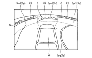
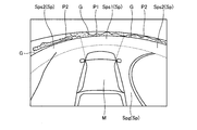
- FIG. 8 is a view for explaining changing the projection position of the captured image data with respect to the side surface Sps of the virtual projection plane Sp by the correction performed by the correction unit 30, and a three-dimensional peripheral image generated by the peripheral image generation unit 36.
- FIG. 8 is based on a first image based on first captured image data captured by the imaging unit 15 c as a first imaging unit and second captured image data captured by the imaging unit 15 d as a second imaging unit. It is explanatory drawing in the case of projecting the 2nd image on side Sps of virtual projection plane Sp.
- the correction by the correction unit 30 is not performed, and the image content deviation occurs in the height direction as shown in FIG. 9, and the correction by the correction unit 30 is performed, as shown in FIG. 10. It is a figure explaining the case where the shift
- the object T exists at a position different from the position of the side surface Sps of the virtual projection plane Sp (for example, when it exists at a position further forward than the position of the side surface Sps)
- a point S0 (X0) on the side surface Sps of the virtual projection plane Sp , Y0, Z0) reflect (projected) the image existing on the extension line Q1 of the imaging unit 15c (first imaging unit).
- the object T appears (includes) in the first captured image data captured by the imaging unit 15c with respect to the point S0 on the side surface Sps.
- the second captured image data imaged by the imaging unit 15d is projected to the point S0 on the side surface Sps. Even if the object T does not appear (is not included). In this case, the object T appears at a position slightly above the point S0 on the side surface Sps.
- the portions appearing on the extension of the imaging unit 15c (first imaging unit) and the imaging unit 15d (second imaging unit) are different, the first image captured by the imaging unit 15c and the image captured by the imaging unit 15d When the second image is formed on the side surface Sps of the virtual projection plane Sp, the projection position of the object T is shifted in the height direction.
- the height from the horizontal line G of the second image P2 captured by the imaging unit 15d (second imaging unit) projected on the side surface Sps2 is deviated.
- the horizontal line G of the first image P1 and the horizontal line G of the second image P2 are made to coincide with each other by changing the shape of the three-dimensional shape model, unevenness is generated at the upper end of the three-dimensional shape model. Unnaturalness also occurs in the shape of the outer edge of the peripheral image.
- the connection portion between the bottom surface Spg and the side surface Sps of the virtual projection plane Sp is displaced, which may cause a new sense of discomfort in the three-dimensional peripheral image.
- the correction unit 30 corrects the projection position of at least one of the first image P1 and the second image P2 projected on the virtual projection plane Sp based on the difference between the height positions of the imaging units 15.
- the first height position (first height H1) of the imaging unit 15c (first imaging unit) and the second height position (second height) of the imaging unit 15d (second imaging unit) The projection position of at least one of the first image P1 and the second image P2 to be projected on the virtual projection plane Sp based on the height ratio with H2) (see FIG.
- the corrected point S1 The three-dimensional coordinates (X0, Y1, Z0) are lower than the three-dimensional coordinates (X0, Y0, Z0) of the point S0 before correction. As shown in FIG. 8, the three-dimensional coordinates of the point S0 are present on the extension line Q3 of the imaging unit 15c (first imaging unit) passing through the three-dimensional coordinates (X0, Y1, Z0) of the point S1.
- the image combining unit 32 converts the two-dimensional coordinates (U, V) of the first image P1 corresponding to the three-dimensional coordinates (X0, Y1, Z0) of the point S1 after correction on the three-dimensional coordinates (X0, 0) of the point S0.
- the projection position of the first image P1 follows the height ratio of the first height position (first height H1) to the second height position (second height H2) on the side surface Sps. Corrected upward, the content of the first image P1 and the content of the second image P2 can be aligned in the height direction.
- the image combining unit 32 generates data of one captured image joined at the boundary portion in a state where the contents of the first image P1 and the content of the second image P2 substantially match.
- the horizontal line G of the first image P1 captured by the imaging unit 15c (first imaging unit) and projected onto the side surface Sps1 of the virtual projection plane Sp, the imaging unit 15d and the imaging unit 15b The horizontal line G of the second image P2 captured by the second imaging unit and projected onto the side surface Sps2 of the virtual projection plane Sp substantially matches. Therefore, it is possible to display a three-dimensional peripheral image with reduced discomfort.
- the left and right door mirrors 2g of the vehicle 1 have different angles from the left and right because the distance from the driver's seat is different.
- height positions (ground heights) of the imaging unit 15b and the imaging unit 15d fixed to the left and right door mirrors 2g are different. Therefore, the second height position (second height H2) when calculating the height component Y1 is the average value of the second height positions (second height H2) of the imaging unit 15b and the imaging unit 15d. May be used.
- the display deviation of the first image P1 can be appropriately reduced with respect to the second image P2 synthesized on the left and right sides of the first image P1.
- the calculation of the three-dimensional coordinates (X0, Y1, Z0) of the point S1 by the correction unit 30 is, for example, when the power of the vehicle 1 is turned on, for example, when the ignition switch is turned on.
- the position may be acquired from specification data stored in the ROM 14 b or the like and executed once, and the result may be stored in the ROM 14 b or the SSD 14 f.
- the image acquisition unit 26 acquires captured image data of the imaging unit 15 (at the time of drawing each frame)
- the image combining unit 32 performs the first image P1 in which the correction in the height direction is performed, and the second image P2 and P2 are combined at the boundary portion to generate one captured image data.
- the three-dimensional processing unit 34 and the peripheral image generation unit 36 use the captured image data on which the height alignment has been performed based on the setting state of the viewpoint Ep and the gaze point En, to generate the peripheral image as shown in FIG.
- the drawing position of the second image P2 captured by the imaging unit 15d and the imaging unit 15d is a first height position (first height H1) and a second height position. It may be corrected downward according to the height with (the second height H2).
- the content in the height direction of the content of the first image P1 and the content of the second image P2 can be aligned, and the content of the first image P1 and the content of the second image P2 does not feel uncomfortable at the boundary portion
- the connected peripheral image can be displayed.
- the shape of the virtual projection plane Sp is not changed, and thus the shape of the outer edge portion or the like of the three-dimensional composite image to be displayed is not changed. Therefore, it is possible to reduce the display deviation of the image content in the height direction without reducing the marketability of the display image.
- the rising position of the side surface Sps from the bottom surface Spg in the virtual projection surface Sp is fixed. Inconsistencies may occur in the displayed contents. For example, as shown in FIG. 11, when the object T1 exists at a position closer to the vehicle 1 than the side surface Sps, the object T1 is displayed across the bottom surface Spg and the side surface Sps when the object T1 is projected on the virtual projection plane Sp. Be done. As a result, a virtual projection image Ip1 larger (longer) than the actual object T1 may be displayed, and an object larger than the actual object T1 may be displayed on the display device 8 (see FIG. 3).
- the object position acquisition unit 38 acquires the position of the object, for example, the distance to the object T1. Do. Then, the variable setting unit 40 sets the projection plane acquisition unit 28 to acquire a virtual projection plane Sp in which the side surface Sps3 rises from the position of the object T1 acquired by the object position acquisition unit 38.
- variable setting unit 40 stores, in the ROM 14b and the SSD 14f, a plurality of virtual projection planes Sp having different widths of the bottom surface Spg (virtual projection planes Sp having different rising positions of the side surface Sps from the vehicle shape model M) If it is, the projection plane acquisition unit 28 sends a control signal so as to read out the virtual projection plane Sp corresponding to the distance to the object T1. Further, the variable setting unit 40 calculates a three-dimensional shape model that defines a virtual projection plane Sp having the side surface Sps3 rising from the position according to the position of the object T1 acquired by the object position acquisition unit 38, It may be provided to the acquisition unit 28.
- a virtual projection image Ip2 having a size (height) closer to a real image is displayed in a three-dimensional virtual space can do.
- the ECU 14 may notify the presence of the object T1 via the display device 8 or the audio output device 9. Also, it may be informed that the side surface Sps of the virtual projection plane Sp is set to the position of the object T1.
- the detection of the object T1 may be performed by image recognition, for example, instead of the distance measuring units 16 and 17.
- the imaging unit 15 is configured by a stereo camera, the distance to the object T1 can be detected by known image processing.
- the display control system 100 can change the position of the viewpoint Ep, for example, by the operation of the operation input unit 10, and faces almost horizontally from the lower viewpoint Ep as viewed three-dimensionally as viewed from a higher viewpoint Ep. It is possible to display three-dimensional peripheral images.
- the viewpoint Ep in front of the vehicle 1 and setting the gaze point En behind the vehicle 1, it is possible to display a three-dimensional peripheral image facing the rear of the vehicle 1.
- the same effect as displaying the front can be obtained. be able to.
- the point S1 is used when the correction unit 30 calculates the height ratio based on the height position of each imaging unit 15 each time the ignition switch is turned on, and corrects the projection position of the first image.
- An example of calculating three-dimensional coordinates (X0, Y1, Z0) of The height position of each imaging unit 15 is fixed at a vehicle manufacturing plant, a dealer, or the like, and thereafter, it is generally not changed except for repair, replacement, etc. of the imaging unit 15. Therefore, using a height ratio based on the height position of each imaging unit 15 in advance in a manufacturing plant or dealer, for example, the three-dimensional coordinates (X0, Y1, Z0) of point S1 used when correcting the projection position of the first image.
- the virtual projection surface Sp may be configured by only the side surface Sps . That is, as the image displayed on the display device 8, only the rising surface at a position away from the vehicle 1 by a predetermined distance is displayed.
- the correction unit 30 sets the first height position (first height H1) of the first imaging unit (for example, the imaging unit 15c) and the second height position of the second imaging unit (for example, the imaging units 15b and 15d).
- the content (projection position) of the image projected on the side surface Sps (virtual projection plane Sp) may be corrected using the difference (difference) in height position (second height H2).
Abstract
車両の第一の高さ位置に設けられた第1撮像部から得られる第1画像と、第一の高さ位置とは異なる第二の高さ位置に設けられて第一の方向とは異なる第二の方向の状況を撮像する第2撮像部から得られる第2画像と、を取得する画像取得部と、第1画像および第2画像を投影可能で、車両の接地面から高さ方向に立ち上がる側面を少なくとも備える三次元の仮想投影面を取得する投影面取得部と、第一の高さ位置と第二の高さ位置との差に基づき、仮想投影面に投影する第1画像の内容と第2画像の内容とが整合するように高さ方向に補正する補正部と、補正によって高さ方向の整合が取れた第1画像と第2画像を含む三次元合成画像を生成する画像合成部と、を備える。
Description
本発明の実施形態は、表示制御装置に関する。
従来、車両の周囲に設けられた複数の撮像部によって、車両の周辺を撮像して、その撮像された複数の撮像画像データを合成し三次元の合成俯瞰画像を生成して、車室内の表示装置で表示することで、車両の周囲の状況を運転者に認識させる俯瞰画像生成装置が提案されている(例えば、特許文献1参照)。
この俯瞰画像生成装置では、各方向(車両の前後左右)を撮像する撮像部の設置高さ(設置地上高)の違いに起因する合成画像の高さ方向のずれを解消している。具体的には、俯瞰画像(三次元空間モデル)の一部の高さ方向の形状を変化させて、水平線の位置を合わせることで、表示される合成俯瞰画像の水平線部分の違和感が出ないようにしている。
しかしながら、従来技術において、水平線の位置を合わせるために三次元空間モデルの高さ方向の一部の形状を変化させることで、投影する画像の水平線の位置を合わせている。その結果、合成俯瞰画像の上端部の形状に凹凸が生じて、表示装置に表示した場合、表示画像の縁部等の形状が不自然となり、商品性の低下を招いてしまうという問題があった。
そこで、本発明の課題の一つは、三次元合成画像の縁部等の形状に不自然さを伴うことなく、高さ方向の画像内容の表示ずれが軽減可能な表示制御装置を提供することにある。
実施形態の表示制御装置は、例えば、車両の第一の高さ位置に設けられて上記車両の周囲のうち第一の方向の状況を撮像する第1撮像部から得られる第1画像と、上記第一の高さ位置とは異なる第二の高さ位置に設けられて上記第一の方向とは異なる第二の方向の状況を撮像する第2撮像部から得られる第2画像と、を取得する画像取得部と、上記第1画像および上記第2画像を投影可能で、上記車両の接地面から高さ方向に立ち上がる側面を少なくとも備える三次元の仮想投影面を取得する投影面取得部と、上記第一の高さ位置と上記第二の高さ位置との差に基づき、上記仮想投影面に投影する上記第1画像と上記第2画像のうち少なくとも一方の投影位置を上記第1画像の内容と上記第2画像の内容とが整合するように高さ方向に補正する補正部と、補正によって高さ方向の整合が取れた上記第1画像と上記第2画像を含む三次元合成画像を生成する画像合成部と、を備える。この構成によれば、例えば、第1撮像部の第一の高さ位置と第2撮像部の第二の高さ位置とで違いがある場合、その高さ位置の差に基づき仮想投影面に投影する画像の内容(投影位置)を補正する。この場合、仮想投影面の形状は変更されないため、表示される三次元合成画像の外縁部等の形状に変化はなく、表示画像の商品性の低下を伴うことなく、高さ方向の画像内容の表示ずれを軽減することができる。
また、実施形態の表示制御装置の上記補正部は、例えば、上記第一の高さ位置と上記第二の高さ位置との高さ比に基づき、上記投影位置を補正するようにしてもよい。この構成によれば、例えば、第1撮像部の第一の高さ位置と第2撮像部の第二の高さ位置の違いに起因する表示ずれをより適正に補正することができる。
また、実施形態の表示制御装置は、例えば、さらに、上記車両の周囲に存在する物体の位置を検出可能な位置検出部を備え、上記投影面取得部は、上記物体の位置に対応する位置に上記側面を備える上記仮想投影面を取得するようにしてもよい。この構成によれば、検出した物体、例えば、他車両の存在する位置に仮想投影面の側面が形成されるので、注意を払うべき物体の形状(大きさ)をより現実に似せた態様で表示できるとともに、高さ方向のずれ(水平線のずれ)が軽減された状態で表示可能となる。その結果、視認性、画像品質、商品性等の向上に、さらに寄与できる。
以下、本発明の例示的な実施形態が開示される。以下に示される実施形態の構成、ならびに当該構成によってもたらされる作用、結果、および効果は、一例である。本発明は、以下の実施形態に開示される構成以外によっても実現可能であるとともに、基本的な構成に基づく種々の効果や、派生的な効果のうち、少なくとも一つを得ることが可能である。
本実施形態において、表示制御装置(表示制御システム)を搭載する車両1は、例えば、不図示の内燃機関を駆動源とする自動車、すなわち内燃機関自動車であってもよいし、不図示の電動機を駆動源とする自動車、すなわち電気自動車や燃料電池自動車等であってもよい。また、それらの双方を駆動源とするハイブリッド自動車であってもよいし、他の駆動源を備えた自動車であってもよい。また、車両1は、種々の変速装置を搭載することができるし、内燃機関や電動機を駆動するのに必要な種々の装置、例えばシステムや部品等を搭載することができる。駆動方式としては、四つある車輪3すべてに駆動力を伝え、四輪すべてを駆動輪として用いる四輪駆動車両とすることができる。車輪3の駆動に関わる装置の方式や、数、レイアウト等は、種々に設定することができる。また、駆動方式も四輪駆動方式に限定されず、例えば、前輪駆動方式や後輪駆動方式でもよい。
図1に例示されるように、車体2は、不図示の乗員が乗車する車室2aを構成している。車室2a内には、乗員としての運転者の座席2bに臨む状態で、操舵部4や、加速操作部5、制動操作部6、変速操作部7等が設けられている。操舵部4は、例えば、ダッシュボード24から突出したステアリングホイールであり、加速操作部5は、例えば、運転者の足下に位置されたアクセルペダルである。また、制動操作部6は、例えば、運転者の足下に位置されたブレーキペダルであり、変速操作部7は、例えば、センターコンソールから突出したシフトレバーである。なお、操舵部4、加速操作部5、制動操作部6、変速操作部7等は、これらには限定されない。
また、車室2a内には、表示装置8や、音声出力装置9が設けられている。表示装置8は、例えば、LCD(liquid crystal display)や、OELD(organic electroluminescent display)等である。音声出力装置9は、例えば、スピーカである。また、表示装置8は、例えば、タッチパネル等、透明な操作入力部10で覆われている。乗員は、操作入力部10を介して表示装置8の表示画面に表示される画像を視認することができる。また、乗員(運転者等)は、表示装置8の表示画面に表示される画像に対応した位置で手指等で操作入力部10を触れたり押したり動かしたりして操作することで、操作入力を実行することができる。これら表示装置8や、音声出力装置9、操作入力部10等は、例えば、ダッシュボード24の車幅方向すなわち左右方向の中央部に位置されたモニタ装置11に設けられている。モニタ装置11は、スイッチや、ダイヤル、ジョイスティック、押しボタン等の不図示の操作入力部を有することができる。また、モニタ装置11とは異なる車室2a内の他の位置に不図示の音声出力装置を設けることができるし、モニタ装置11の音声出力装置9と他の音声出力装置から、音声を出力することができる。なお、モニタ装置11は、例えば、ナビゲーションシステムやオーディオシステムと兼用されうる。
また、図1、図2に例示されるように、車両1は、例えば、四輪自動車であり、左右二つの前輪3Fと、左右二つの後輪3Rとを有する。これら四つの車輪3は、いずれも転舵可能に構成されうる。図3に例示されるように、車両1は、少なくとも二つの車輪3を操舵する操舵システム13を有している。操舵システム13は、アクチュエータ13aと、トルクセンサ13bとを有する。操舵システム13は、ECU14(electronic control unit)等によって電気的に制御されて、アクチュエータ13aを動作させる。操舵システム13は、例えば、電動パワーステアリングシステムや、SBW(steer by wire)システム等である。操舵システム13は、アクチュエータ13aによって操舵部4にトルク、すなわちアシストトルクを付加して操舵力を補ったり、アクチュエータ13aによって車輪3を転舵したりする。この場合、アクチュエータ13aは、一つの車輪3を転舵してもよいし、複数の車輪3を転舵してもよい。また、トルクセンサ13bは、例えば、運転者が操舵部4に与えるトルクを検出する。
また、図2に例示されるように、車体2には、複数の撮像部15として、例えば四つの撮像部15a~15dが設けられている。撮像部15は、例えば、CCD(Charge Coupled Device)やCIS(CMOS image sensor)等の撮像素子を内蔵するデジタルカメラである。撮像部15は、所定のフレームレートで動画データ(撮像画像データ)を出力することができる。撮像部15は、それぞれ、広角レンズまたは魚眼レンズを有し、水平方向には例えば140°~220°の範囲を撮影することができる。また、撮像部15の光軸は斜め下方に向けて設定されている場合もある。よって、撮像部15は、車両1が移動可能な路面や物体(障害物として、例えば、岩、樹木、人間、自転車、車両等)を含む車両1の外部の周辺の環境を逐次撮影し、撮像画像データとして出力する。
撮像部15aは、例えば、車体2の後側の端部2eに位置され、リアハッチのドア2hのリアウインドウの下方の壁部に設けられている。撮像部15bは、例えば、車体2の右側の端部2fに位置され、右側のドアミラー2gに設けられている。撮像部15cは、例えば、車体2の前側、すなわち車両前後方向の前方側の端部2cに位置され、フロントバンパやフロントグリル等に設けられている。撮像部15dは、例えば、車体2の左側の端部2dに位置され、左側のドアミラー2gに設けられている。
また、図3に例示されるように、表示制御システム100(表示制御装置)では、ECU14や、モニタ装置11、操舵システム13等の他、ブレーキシステム18、舵角センサ19、アクセルセンサ20、シフトセンサ21、車輪速センサ22等が、電気通信回線としての車内ネットワーク23を介して電気的に接続されている。車内ネットワーク23は、例えば、CAN(controller area network)として構成されている。ECU14は、車内ネットワーク23を通じて制御信号を送ることで、操舵システム13、ブレーキシステム18等を制御することができる。また、ECU14は、車内ネットワーク23を介して、トルクセンサ13b、ブレーキセンサ18b、舵角センサ19、アクセルセンサ20、シフトセンサ21、車輪速センサ22の検出結果や、操作入力部10等の操作信号等を、受け取ることができる。
また、図1、図2に例示されるように、車体2には、複数の測距部16,17として、例えば四つの測距部16a~16dと、八つの測距部17a~17hとが設けられている。測距部16,17は、例えば、超音波を発射してその反射波を捉えるソナーである。ソナーは、ソナーセンサ、あるいは超音波探知器とも称されうる。ECU14は、測距部16,17の検出結果により、車両1の周囲に位置された障害物等の物体の有無や当該物体までの距離(位置)を測定することができる。したがって、測距部16,17は、車両1の周囲に存在する物体の位置を検出する位置検出部として機能する。なお、測距部17は、例えば、比較的近距離の物体の検出に用いられ、測距部16は、例えば、測距部17よりも遠い比較的長距離の物体の検出に用いられうる。また、測距部17は、例えば、車両1の前方および後方の物体の検出に用いられ、測距部16は、車両1の側方の物体の検出に用いられうる。
ECU14は、例えば、CPU14a(central processing unit)や、ROM14b(read only memory)、RAM14c(random access memory)、表示制御部14d、音声制御部14e、SSD14f(solid state drive、フラッシュメモリ)等を有している。CPU14aは、ROM14b等の不揮発性の記憶装置に記憶された(インストールされた)プログラムを読み出し、当該プログラムに従って演算処理を実行する。CPU14aは、例えば、表示装置8で表示される画像に関連した画像処理を実行する。例えば、CPU14aは、撮像部15が撮像した撮像画像データに演算処理や画像処理を実行して、三次元の周辺画像(例えば、俯瞰画像)を生成する。CPU14aは、生成する周辺画像の視点を変化させることができる。また、CPU14aは、車両1の周囲に注意すべき物体(例えば、他車両や壁、歩行者等の障害物)が存在するか否かを検出したり、検出した物体の位置に基づいて周辺画像の表示態様を変化させたりすることができる。また、CPU14aは、検出した物体に基づき、ユーザ(運転者や搭乗者)に物体の存在を報知する処理も実行可能である。
RAM14cは、CPU14aでの演算で用いられる各種のデータを一時的に記憶する。また、表示制御部14dは、ECU14での演算処理のうち、主として、表示装置8で表示される画像データの合成等を実行する。また、音声制御部14eは、ECU14での演算処理のうち、主として、音声出力装置9で出力される音声データの処理を実行する。SSD14fは、書き換え可能な不揮発性の記憶部であって、ECU14の電源がオフされた場合にあってもデータを記憶することができる。なお、CPU14aや、ROM14b、RAM14c等は、同一パッケージ内に集積されうる。また、ECU14は、CPU14aに替えて、DSP(digital signal processor)等の他の論理演算プロセッサや論理回路等が用いられる構成であってもよい。また、SSD14fに替えてHDD(hard disk drive)が設けられてもよいし、SSD14fやHDDは、ECU14とは別に設けられてもよい。
ブレーキシステム18は、例えば、ブレーキのロックを抑制するABS(anti-lock brake system)や、コーナリング時の車両1の横滑りを抑制する横滑り防止装置(ESC:electronic stability control)、ブレーキ力を増強させる(ブレーキアシストを実行する)電動ブレーキシステム、BBW(brake by wire)等である。ブレーキシステム18は、アクチュエータ18aを介して、車輪3ひいては車両1に制動力を与える。また、ブレーキシステム18は、左右の車輪3の回転差などからブレーキのロックや、車輪3の空回り、横滑りの兆候等を検出して、各種制御を実行することができる。ブレーキセンサ18bは、例えば、制動操作部6の可動部の位置を検出するセンサである。
舵角センサ19は、例えば、ステアリングホイール等の操舵部4の操舵量を検出するセンサである。ECU14は、運転者による操舵部4の操舵量や、自動操舵時の各車輪3の操舵量等を、舵角センサ19から取得して各種制御を実行する。アクセルセンサ20は、例えば、加速操作部5の可動部の位置を検出するセンサである。シフトセンサ21は、例えば、変速操作部7の可動部の位置を検出するセンサである。車輪速センサ22は、車輪3の回転量や単位時間当たりの回転数を検出するセンサである。車輪速センサ22は、検出した回転数を示す車輪速パルス数をセンサ値として出力する。ECU14は、車輪速センサ22から取得したセンサ値に基づいて車両1の移動量などを演算し、各種制御を実行する。
なお、上述した各種センサやアクチュエータの構成や、配置、電気的な接続形態等は、一例であって、種々に設定(変更)することができる。
ECU14に含まれるCPU14aは、上述したように撮像部15が撮像した撮像画像データに基づいた車両1周辺の環境を例えば、三次元の俯瞰態様の画像で表示する。この機能を実現するために、CPU14aは、図4に示すような種々のモジュールを含んでいる。CPU14aは、例えば、画像取得部26、投影面取得部28、補正部30、画像合成部32、三次元処理部34、周辺画像生成部36、物体位置取得部38、可変設定部40等を含む。これらのモジュールは、ROM14b等の記憶装置にインストールされ記憶されたプログラムを読み出し、それを実行することで実現可能である。
画像取得部26は、車両1の周囲を表示するために必要な情報を取得する。例えば、画像取得部26は、車両1の周辺を撮像する複数の撮像部15から、複数の撮像画像データを取得する。なお、本実施形態において、撮像部15は、車体2(車両1)における設置位置に応じて、固定されている高さ位置が異なる。図1、図5に示されるように撮像部15bおよび撮像部15dは例えばドアミラー2gに固定される。一方、撮像部15cは、図5に示されるように車体2の端部2cで、ドアミラー2gより低い位置、例えばフロントグリルに固定される。本実施形態において、撮像部15cは、車両1の第一の高さ位置(第1高さH1)に設けられて車両1の周囲のうち第一の方向(前方)の状況を撮像する第1撮像部と称し、第1撮像部(撮像部15c)からの撮像画像データを第1撮像画像データと称する場合がある。また、撮像部15bまたは撮像部15dは、第一の高さ位置(第1高さH1)とは異なる第二の高さ位置(第2高さH2)に設けられる。撮像部15bまたは撮像部15dは、第1撮像画像データに基づく第1画像と水平方向において繋ぎ合わせ可能な第二の方向(主として左側方または右側方)の状況を示す第2画像を撮像する第2撮像部と称する場合がある。また、第2撮像部(撮像部15bまたは撮像部15d)からの撮像画像データを第2撮像画像データと称する場合がある。
投影面取得部28は、例えば、ROM14bやSSD14f等に予め記憶された三次元形状モデルを取得する。三次元形状モデルは、例えば、車両1の周囲を取り囲む仮想投影面を規定するデータである。図5~図7に三次元形状モデルの一例を示す。なお、図5は、撮像部15dの撮影画像Icを仮想投影面Sp(Sps)へ投影する例を示す模式図であり、図6は、仮想投影面Spの構成を模式的に示す図であり、図7は、仮想投影面Spの全体を模式的に示す図である。
図6に示すように、三次元形状モデルである仮想投影面Spは、座標(X,Y,Z)が規定されるメッシュ構造のデータで、撮像部15が撮像した撮像画像データの各画素のデータが例えば、メッシュの交点(座標X,Y,Zで規定される交点)に投影される。なお、図6に示す仮想投影面Spのメッシュは、説明のために図示したもので、実際には視認できないように設定されている。
仮想投影面Spは、例えば、図5、図7に示すように、地面Grに沿った底面Spgと、底面Spgすなわち地面Grから立ち上がった側面Spsと、を有している。地面Grは、車両1の高さ方向Y(上下方向)と直交する水平面であり、車輪3の接地面でもある。底面Spgは、例えば略円形の平坦面であり、車両1を基準とする水平面である。側面Spsは、底面Spgと接して底面Spgの一部から高さ方向に立ち上り底面Spgの一部を取り囲む、例えば曲面である。図5に示されるように、側面Spsの、車両1の中心Gcを通り車両1の垂直な仮想断面の形状は、例えば、楕円状あるいは放物線状である。側面Spsは、例えば、車両1の中心Gcを通り車両1の高さ方向に沿う中心線CL周りの回転面として構成される。つまり、側面Spsは、車両1の周囲を取り囲んでいる。
補正部30は、第1画像を示す第1撮像画像データまたは第2画像を示す第2撮像画像データのうち一方のデータの高さ方向の補正を行う。本実施形態において、第一の高さ位置(第1高さH1)に設けられた撮像部15cから撮像した場合の第1撮像画像データと、第二の高さ位置(第2高さH2)に設けられた撮像部15dから撮像した場合の第2撮像画像データと、を三次元形状モデルの仮想投影面Spにそのまま投影した場合、第一の高さ位置(第1高さH1)と第二の高さ位置(第2高さH2)との差異に起因して、高さ方向の表示内容がずれてしまう場合がある。そこで、補正部30は、表示内容のずれを軽減するために、仮想投影面Spに投影する第1撮像画像データまたは第2撮像画像データのうち少なくとも一方(例えば、第1撮像画像データ)の高さ方向の補正を行う。また、撮像部15が備えるレンズは、広範囲の撮像を実現するために広角レンズや魚眼レンズである場合があり、画像に歪みを含む場合がある。補正部30は、レンズの歪みに基づき第1撮像画像データおよび第2撮像画像データの補正を行ってもよい。なお、高さ方向の補正の詳細は後述する。
画像合成部32は、例えば画像取得部26で取得されて補正部30で補正された撮像部15cが撮像した第1撮像画像データと、画像取得部26で取得された撮像部15dおよび撮像部15bが撮像した第2撮像画像データを、それらの境界部分を合成することで繋ぎ、一つの撮像画像データを生成する。なお、第1撮像画像データと第2撮像画像データとを合成する場合、境界部分をそのまま合成すると境界線が明確に現れてしまう場合がある。例えば、撮像部15cの撮像した第1画像と、撮像部15dの撮像した第2画像とで、日光やライトの当たり方等によって画像の明るさや色合いが異なる場合がある。この場合、明るさや色合いの違いによる境界線が現れ、合成された一つの撮像画像データに基づく画像の品質が低下してしまう場合がある。そこで、仮想投影面Spには、第1撮像画像データを投影する側面Sps1の水平方向の端部と第2撮像画像データを投影する側面Sps2の水平方向の端部とが重なる重複領域が設定される。この重複領域においては、画像合成部32は、第1撮像画像データと第2撮像画像データのそれぞれa%を利用して画像を合成するブレンド処理を実行してもよい。ブレンド処理を実行することにより、第1撮像画像データの第1画像と第2撮像画像データの第2画像とが、徐々に変化するように合成され、明るさや色合いの違いによって生じる境界線を目立ちにくくすることができる。
なお、画像合成部32は、ECU14が車両1の後方の状況を示す周辺画像を表示する場合は、同様に、撮像部15aが撮像した第1撮像画像データと撮像部15dおよび撮像部15bが撮像した第2撮像画像データを合成して一つの撮像画像データを生成する。
三次元処理部34は、車両1が存在する位置を基準として定められた、車両1の周囲を取り囲む仮想投影面Sp(三次元形状モデル)に、画像合成部32で合成した撮像画像データを投影した、仮想投影画像のデータを生成する。三次元処理部34は、図5に示すように、撮影画像Icを、仮想投影面Spに投影した仮想投影画像Ipを算出する。撮影画像Icを地面Grに投影すると、撮像部15から遠ざかるにつれて像が長くなり、出力画像中で実際の長さよりも長く映る場合がある。図5からわかるように、地面Gr(底面Spg)から立ち上がった側面Spsへ投影された仮想投影画像Ipは、地面Grに投影された場合に比べて、像が短くなり、出力画像中で実際の長さよりも長く映るのが抑制される。
また、三次元処理部34は、図6、図7に示すように、仮想投影面Spを含む三次元仮想空間内に、ROM14bまたはSSD14f等に記憶されている、車両1に対応する車両形状モデルMを配置する。三次元処理部34は、三次元仮想空間内に配置する車両形状モデルMに、所定の透過率を設定する。これにより、三次元仮想空間において、車両形状モデルMを介して、反対側の仮想投影画像Ipを視認できる。
周辺画像生成部36は、撮像画像データが投影された、三次元仮想空間内の仮想投影面Spに投影された仮想投影画像Ip及び車両形状モデルMを、当該三次元仮想空間内に設定された視点Epから注視点Enを見た周辺画像データを生成する。周辺画像生成部36は、生成した周辺画像データを表示制御部14dに供給し、表示制御部14dは表示装置8に三次元の周辺画像を表示させる。
図7には、車両形状モデルMを中心とする仮想投影面Spの全体が模式的に示されている。周辺画像生成部36は、仮想投影面Spに投影された仮想投影画像Ip(図5参照)を、仮想の視点Epから見た周辺画像データ(図6には不図示)に変換する。図7に示される例では、視点Epは、車両形状モデルMの後方に設定され、車両形状モデルMの前方(注視点En)を見ている場合である。
このように本実施形態の表示制御システム100によれば、車両1に設置された複数の撮像部15で撮像した撮像画像データを合成して、任意の視点Epから注視点Enを見た車両1の周囲の状況を三次元の仮想空間内で表示することで利用者(運転者等)に車両1の周囲の状況を認識させやすくすることができる。
物体位置取得部38は、測距部16や測距部17によって車両1の周囲に物体が検出された場合、例えば他車両や、壁、歩行者等が検出された場合に、その物体の位置、例えば、物体までの距離を取得する。可変設定部40は、物体位置取得部38が取得した物体の位置に応じて、投影面取得部28が取得する三次元形状モデルで規定される仮想投影面Spの側面Spsの位置を設定し得る。例えば、ROM14bやSSD14fに底面Spgの広さが異なる仮想投影面Sp(車両形状モデルMからの側面Spsの立上り位置が異なる仮想投影面Sp)を複数記憶させておく。そして、可変設定部40は、投影面取得部28が三次元形状モデルを取得する場合に、物体の位置に対応した位置(近い位置)から立ち上がる側面Spsを持つ仮想投影面Spを規定する三次元形状モデルを選択させるようにしてもよい。また、別の例では、可変設定部40は、物体位置取得部38が取得した物体の位置に応じて、その位置から立ち上がる側面Spsを持つ仮想投影面Spを規定する三次元形状モデルを算出して、投影面取得部28に提供するようにしてもよい。
図8は、補正部30が実行する補正により仮想投影面Spの側面Spsに対する撮像画像データの投影位置を変化させることを説明する図であり、周辺画像生成部36で生成する三次元の周辺画像(周辺画像データ)の表示内容のずれを軽減する。具体的には、車両1の前方を表示する第1画像と車両1の側方を表示する第2画像の高さ方向のずれを軽減する。
図8は、一例として、第1撮像部としての撮像部15cが撮像する第1撮像画像データに基づく第1画像と、第2撮像部としての撮像部15dが撮像する第2撮像画像データに基づく第2画像と、を仮想投影面Spの側面Spsに投影する場合の説明図である。図8は、補正部30による補正を行わず、図9に示すように高さ方向で画像内容のずれが生じる場合と、補正部30による補正を実行して、図10に示すように高さ方向の画像内容のずれが軽減される場合を説明する図である。
まず、補正部30による補正を実行しない場合を説明する。仮想投影面Spの側面Spsの位置と異なる位置に物体Tが存在する場合(例えば、側面Spsの位置よりさらに前方の位置に存在する場合)、仮想投影面Spの側面Sps上の点S0(X0,Y0,Z0)には、撮像部15c(第1撮像部)の延長線Q1上に存在するものが映る(投影される)。この場合、側面Sps上の点S0に対して、撮像部15cで撮像された第1撮像画像データには、物体Tが映る(含まれる)。一方、撮像部15d(第2撮像部)の延長線Q2上には、物体Tが存在しないので、側面Sps上の点S0に対して、撮像部15dで撮像された第2撮像画像データを投影しても、物体Tが映らない(含まれない)。この場合、側面Spsにおいて点S0の少し上方の位置に物体Tが映る。このように、撮像部15c(第1撮像部)と撮像部15d(第2撮像部)の延長線上に映る部分が異なる場合、撮像部15cで撮像された第1画像と撮像部15dで撮像された第2画像とを仮想投影面Spの側面Sps上で構成した場合、物体Tの投影位置が高さ方向にずれる。その結果、例えば、図9に示すように、仮想投影面Spの側面Sps1に投影される撮像部15c(第1撮像部)で撮像された第1画像P1の水平線Gと、仮想投影面Spの側面Sps2に投影される撮像部15d(第2撮像部)で撮像された第2画像P2の水平線Gとの高さがずれる。仮に、三次元形状モデルの形状を変化させて、第1画像P1の水平線Gと第2画像P2の水平線Gとを一致させようとすると、三次元形状モデルの上端部に凹凸が生じ、表示される周辺画像の外縁部等の形状にも違和感が生じる。また、仮想投影面Spの底面Spgと側面Spsとの接続部分にずれが生じ、三次元の周辺画像に新たな違和感を生じさせてしまう場合がある。
上述したような第1画像P1の水平線Gと第2画像P2の水平線Gのずれは、各撮像部15の高さの違いが主たる原因である。そこで、補正部30は、各撮像部15の高さ位置の差に基づき、仮想投影面Spに投影する第1画像P1と第2画像P2のうち少なくとも一方の投影位置を補正する。具体的には、撮像部15c(第1撮像部)の第一の高さ位置(第1高さH1)と撮像部15d(第2撮像部)の第二の高さ位置(第2高さH2)との高さ比に基づき(図5参照)、仮想投影面Spに投影する第1画像P1と第2画像P2のうち少なくとも一方の投影位置を第1画像P1の内容と第2画像P2の内容とが高さ方向で整合するように補正する。この場合、三次元形状モデルが規定している仮想投影面Spの側面Sps上の点S0の三次元座標(X0,Y0,Z0)に対応する第1画像P1の二次元座標(U,V)の対応関係を算出することになる。つまり、点S0の三次元座標(X0,Y0,Z0)の高さ成分Y0のみを以下に示す(式1)にしたがい修正した高さ成分Y1を含む点S1の三次元座標(X0,Y1,Z0)を算出する。そして、点S1に対応する第1画像P1の二次元座標(U,V)を点S0の三次元座標(X0,Y0,Z0)に投影する。
Y1=Y0×(第1高さH1)/(第2高さH2)・・・・(式1)
Y1=Y0×(第1高さH1)/(第2高さH2)・・・・(式1)
図8の場合、前方を撮影する撮像部15c(第1撮像部)は、側方を撮像する撮像部15d(第2撮像部)より低い位置に固定されているので、補正後の点S1の三次元座標(X0,Y1,Z0)は、補正前の点S0の三次元座標(X0,Y0,Z0)より低い位置になる。図8に示すように、点S1の三次元座標(X0,Y1,Z0)を通過する撮像部15c(第1撮像部)の延長線Q3上に存在するものは、点S0の三次元座標(X0,Y0,Z0)を通過する撮像部15c(第1撮像部)の延長線Q2上に存在するものより、第一の高さ位置(第1高さH1)と第二の高さ位置(第2高さH2)との高さ比にしたがい近くなる。つまり、撮像部15d(第2撮像部)の延長線Q2と地面Grとの交点と、撮像部15c(第1撮像部)の延長線Q3と地面Grの交点とが、ほぼ同じ位置Rとなる。したがって、画像合成部32が、補正後の点S1の三次元座標(X0,Y1,Z0)に対応する第1画像P1の二次元座標(U,V)を点S0の三次元座標(X0,Y0,Z0)の位置に投影することにより、より近い位置の画像を仮想投影面Spの側面Sps上に投影することになる。このように、第1画像P1の投影位置が側面Sps上で第一の高さ位置(第1高さH1)と第二の高さ位置(第2高さH2)との高さ比にしたがい上方に補正され、第1画像P1の内容と第2画像P2の内容とが高さ方向で整合が取れる。したがって、画像合成部32は、第1画像P1と第2画像P2の内容が概ね一致した状態で境界部分で繋ぎ合わされた一つの撮像画像のデータを生成することになる。その結果、図10に示すように、撮像部15c(第1撮像部)で撮像され仮想投影面Spの側面Sps1に投影される第1画像P1の水平線Gと、撮像部15dおよび撮像部15b(第2撮像部)で撮像され仮想投影面Spの側面Sps2に投影される第2画像P2の水平線Gとがほぼ一致する。したがって、違和感が軽減された三次元の周辺画像を表示することができる。
なお、一般的に車両1の左右のドアミラー2gは、運転席からの距離が異なるため、左右で角度が異なる。その結果、左右のドアミラー2gに固定される撮像部15bおよび撮像部15dの高さ位置(地上高)が異なる。したがって、高さ成分Y1を算出する場合の第二の高さ位置(第2高さH2)は、撮像部15bと撮像部15dの第二の高さ位置(第2高さH2)の平均値を用いてもよい。この場合、第1画像P1を挟んで左右に合成される第2画像P2に対して、第1画像P1の表示ずれを、それぞれ適度に軽減することができる。
なお、補正部30による点S1の三次元座標(X0,Y1,Z0)の算出は、例えば、車両1の電源をONしたとき、例えばイグニッションスイッチをONしたときに、各撮像部15の高さ位置をROM14b等に保存された諸元データから取得して一度実行し、その結果をROM14bやSSD14fに保存しておけばよい。そして、画像合成部32は、画像取得部26が撮像部15の撮像画像データを取得する度(毎フレーム描画時)に、高さ方向の補正が行われた第1画像P1と、第2画像P2と、を境界部分で合成して一つの撮像画像データを生成する。そして、三次元処理部34および周辺画像生成部36が、視点Epと注視点Enの設定状態に基づき、高さ整合が行われた撮像画像データを用いて、図10に示すような周辺画像を生成する。
なお、図10に示す例では、撮像部15c(第1撮像部)が撮像した第1画像P1の描画位置を第一の高さ位置(第1高さH1)と第二の高さ位置(第2高さH2)との高さの比にしたがい上方に補正する例を示した。別の実施形態では、撮像部15dおよび撮像部15d(第2撮像部)が撮像した第2画像P2の描画位置を第一の高さ位置(第1高さH1)と第二の高さ位置(第2高さH2)との高さにしたがい下方に補正してもよい。その結果、上述の例と同様に、第1画像P1の内容と第2画像P2の内容との高さ方向の整合が取れ、第1画像P1と第2画像P2の内容が境界部分で違和感なく繋ぎ合わされた周辺画像を表示することができる。
このように、本実施形態の表示制御システム100によれば、仮想投影面Spの形状は変更されないため、表示される三次元の合成画像の外縁部等の形状に変化はない。したがって、表示画像の商品性の低下は伴うことなく、高さ方向の画像内容の表示ずれを軽減することができる。なお、補正部30は、仮想投影面Spの側面Sps上で一律に高さ成分Y1を例えば、Y1=Y-αのように補正するのではなく、第一の高さ位置(第1高さH1)と第二の高さ位置(第2高さH2)との高さの比にしたがい補正する。その結果、仮想投影面Spの底面Spgと側面Spsとの境界部分のずれが生じない。したがって、仮想投影面Sp全体としても違和感のない表示が実現できる。
ところで、上述のように、仮想投影面Spの側面Sps上で高さ方向の表示ずれが軽減される場合でも、仮想投影面Spにおける底面Spgからの側面Spsの立上り位置が固定されている場合、表示内容に違和感が生じる場合がある。例えば、図11に示すように、側面Spsより車両1に近い位置に物体T1が存在する場合、物体T1を仮想投影面Spに投影すると、物体T1が底面Spgおよび側面Spsに跨がって表示される。その結果、実際の物体T1より大きい(長い)仮想投影画像Ip1が表示され、表示装置8(図3参照)には、実際の物体T1より大きな物体が存在するように表示されることがある。
そこで、物体位置取得部38は、測距部16や測距部17(図3参照)によって車両1の周囲に物体が検出された場合、その物体の位置、例えば、物体T1までの距離を取得する。そして、可変設定部40は、物体位置取得部38が取得した物体T1の位置から側面Sps3が立ち上がるような仮想投影面Spを投影面取得部28が取得するように設定する。上述したように、可変設定部40は、ROM14bやSSD14fに底面Spgの広さが異なる仮想投影面Sp(車両形状モデルMからの側面Spsの立上り位置が異なる仮想投影面Sp)を複数記憶している場合は、投影面取得部28が、物体T1までの距離に対応する仮想投影面Spを読み出してくるように制御信号を送出する。また、可変設定部40は、物体位置取得部38が取得した物体T1の位置に応じて、その位置から立ち上がる側面Sps3を持つ仮想投影面Spを規定する三次元形状モデルを算出して、投影面取得部28に提供するようにしてもよい。この場合、物体T1は、側面Sps3に投影され、底面Spgには実質的に投影されないので、より実物のイメージに近い大きさ(高さ)の仮想投影画像Ip2を三次元の仮想空間内に表示することができる。そして、撮像部15d(第2撮像部)の延長線Q2と地面Grとの交点と、撮像部15c(第1撮像部)の延長線Q3と地面Grの交点とが、ほぼ同じ位置Rとなるように、補正後の点S1の三次元座標(X0,Y1,Z0)に対応する第1画像P1の二次元座標(U,V)を点S0の三次元座標(X0,Y0,Z0)の位置に投影する。その結果、実物の物体T1の大きさを認識しやすく、かつ高さ方向の表示ずれが軽減された、より違和感が軽減された三次元の周辺画像の表示が可能になる。つまり、さらに品質の高い周辺画像の表示が可能になる。
なお、ECU14は、測距部16,17によって物体T1が検出された場合に、その物体T1の存在を表示装置8や音声出力装置9を介して報知してもよい。また、仮想投影面Spの側面Spsが物体T1の位置に設定されたことを報知してもよい。また、物体T1の検出は、測距部16,17に代えて、例えば、画像認識によって行ってもよい。例えば、撮像部15をステレオカメラで構成すれば、周知の画像処理により物体T1までの距離を検出できる。
なお、上述した実施形態では、車両1の前方を臨む三次元の周辺画像を表示する例を示した。表示制御システム100は、例えば操作入力部10の操作等により視点Epの位置を変更可能であり、より高い視点Epから見下ろしたような三次元の俯瞰表示や、より低い視点Epからほぼ水平を臨む三次元の周辺画像の表示が可能である。同様に、視点Epを車両1の前方に設定して注視点Enを車両1の後方に設定すれば、車両1の後方を臨む三次元の周辺画像を表示することが可能である。この場合、第1画像P1として撮像部15aが撮像した画像を用い、第2画像P2として撮像部15bおよび撮像部15dが撮像した画像を用いることにより、前方を表示する場合と同様の効果を得ることができる。
上述した例では、イグニッションスイッチがONされる度に、補正部30が各撮像部15の高さ位置に基づく高さ比を算出して、第1画像の投影位置を補正するときに用いる点S1の三次元座標(X0,Y1,Z0)の算出を行う例を示した。各撮像部15の高さ位置は、車両の製造工場やディーラ等で固定され、それ以降は撮像部15の修理や交換等以外は一般的には変更されない。したがって、製造工場やディーラ等で予め各撮像部15の高さ位置に基づく高さ比を用い、例えば第1画像の投影位置を補正するときに用いる点S1の三次元座標(X0,Y1,Z0)を算出し、対応する二次元座標(U,V)をROM14bやSSD14fに保存しておいてもよい。この場合、ECU14の処理負担が軽減され、比較的性能の低いECU14の利用も可能になり、ECU14を選定する際の選択範囲が広がったり、低コストのECU14の利用が可能になったりする利点がある。
上述した実施形態では、仮想投影面Spは、底面Spgと側面Spsとで構成される例を示したが、他の実施形態においては、仮想投影面Spが側面Spsだけで構成されていてもよい。つまり、表示装置8に表示される画像は、車両1から所定距離離れた位置の立上り面のみが表示される。この場合、補正部30は、第1撮像部(例えば撮像部15c)の第一の高さ位置(第1高さH1)と第2撮像部(例えば、撮像部15b,15d)の第二の高さ位置(第2高さH2)の差(違い)を用いて、側面Sps(仮想投影面Sp)に投影する画像の内容(投影位置)を補正してもよい。この場合も、側面Sps(仮想投影面Sp)の形状は変更されないため、表示される三次元合成画像の外縁部等の形状に変化はなく、表示画像の商品性の低下を伴うことなく、高さ方向の画像内容の表示ずれを軽減することができる。
本発明のいくつかの実施形態を説明したが、これらの実施形態は、例として提示したものであり、発明の範囲を限定することは意図していない。これら新規な実施形態は、その他の様々な形態で実施されることが可能であり、発明の要旨を逸脱しない範囲で、種々の省略、置き換え、変更を行うことができる。これら実施形態やその変形は、発明の範囲や要旨に含まれるとともに、請求の範囲に記載された発明とその均等の範囲に含まれる。
1…車両、8…表示装置、10…操作入力部、14…ECU、14a…CPU、15…撮像部、15b,15d…撮像部(第2撮像部)、15c…撮像部(第1撮像部)、16,17…測距部、26…画像取得部、28…投影面取得部、30…補正部、32…画像合成部、34…三次元処理部、36…周辺画像生成部、38…物体位置取得部、40…可変設定部、100…表示制御システム、H1…第1高さ(第一の高さ位置)、H2…第2高さ(第二の高さ位置)、Sp…仮想投影面、P1…第1画像、P2…第2画像。
Claims (3)
- 車両の第一の高さ位置に設けられて前記車両の周囲のうち第一の方向の状況を撮像する第1撮像部から得られる第1画像と、前記第一の高さ位置とは異なる第二の高さ位置に設けられて前記第一の方向とは異なる第二の方向の状況を撮像する第2撮像部から得られる第2画像と、を取得する画像取得部と、
前記第1画像および前記第2画像を投影可能で、前記車両の接地面から高さ方向に立ち上がる側面を少なくとも備える三次元の仮想投影面を取得する投影面取得部と、
前記第一の高さ位置と前記第二の高さ位置との差に基づき、前記仮想投影面に投影する前記第1画像と前記第2画像のうち少なくとも一方の投影位置を前記第1画像の内容と前記第2画像の内容とが整合するように高さ方向に補正する補正部と、
補正によって高さ方向の整合が取れた前記第1画像と前記第2画像を含む三次元合成画像を生成する画像合成部と、
を備える表示制御装置。 - 前記補正部は、前記第一の高さ位置と前記第二の高さ位置との高さ比に基づき、前記投影位置を補正する請求項1に記載の表示制御装置。
- さらに、前記車両の周囲に存在する物体の位置を検出可能な位置検出部を備え、
前記投影面取得部は、前記物体の位置に対応する位置に前記側面を備える前記仮想投影面を取得する請求項1または請求項2に記載の表示制御装置。
Priority Applications (3)
| Application Number | Priority Date | Filing Date | Title |
|---|---|---|---|
| US16/632,930 US11383642B2 (en) | 2017-08-03 | 2018-02-21 | Display control apparatus |
| CN201880048325.3A CN110945558B (zh) | 2017-08-03 | 2018-02-21 | 显示控制装置 |
| EP18842006.1A EP3664014B1 (en) | 2017-08-03 | 2018-02-21 | Display control device |
Applications Claiming Priority (2)
| Application Number | Priority Date | Filing Date | Title |
|---|---|---|---|
| JP2017150671A JP7039879B2 (ja) | 2017-08-03 | 2017-08-03 | 表示制御装置 |
| JP2017-150671 | 2017-08-03 |
Publications (1)
| Publication Number | Publication Date |
|---|---|
| WO2019026320A1 true WO2019026320A1 (ja) | 2019-02-07 |
Family
ID=65233362
Family Applications (1)
| Application Number | Title | Priority Date | Filing Date |
|---|---|---|---|
| PCT/JP2018/006260 WO2019026320A1 (ja) | 2017-08-03 | 2018-02-21 | 表示制御装置 |
Country Status (5)
| Country | Link |
|---|---|
| US (1) | US11383642B2 (ja) |
| EP (1) | EP3664014B1 (ja) |
| JP (1) | JP7039879B2 (ja) |
| CN (1) | CN110945558B (ja) |
| WO (1) | WO2019026320A1 (ja) |
Cited By (1)
| Publication number | Priority date | Publication date | Assignee | Title |
|---|---|---|---|---|
| EP3761262A1 (en) * | 2019-07-04 | 2021-01-06 | DENSO TEN Limited | Image processing device and image processing method |
Families Citing this family (6)
| Publication number | Priority date | Publication date | Assignee | Title |
|---|---|---|---|---|
| WO2018131165A1 (ja) * | 2017-01-16 | 2018-07-19 | 富士通株式会社 | 情報処理プログラム、情報処理方法および情報処理装置 |
| JP6962372B2 (ja) * | 2017-08-25 | 2021-11-05 | 株式会社ソシオネクスト | 補正装置、補正プログラム及び記録媒体 |
| JP6909151B2 (ja) * | 2017-12-28 | 2021-07-28 | アルパイン株式会社 | 車載システム |
| DE102018214875A1 (de) * | 2018-08-31 | 2020-03-05 | Audi Ag | Verfahren und Anordnung zum Erzeugen einer Umgebungsrepräsentation eines Fahrzeugs und Fahrzeug mit einer solchen Anordnung |
| WO2020068960A1 (en) * | 2018-09-26 | 2020-04-02 | Coherent Logix, Inc. | Any world view generation |
| US11948315B2 (en) * | 2020-12-31 | 2024-04-02 | Nvidia Corporation | Image composition in multiview automotive and robotics systems |
Citations (2)
| Publication number | Priority date | Publication date | Assignee | Title |
|---|---|---|---|---|
| JP2016225865A (ja) | 2015-06-01 | 2016-12-28 | 東芝アルパイン・オートモティブテクノロジー株式会社 | 俯瞰画像生成装置 |
| WO2017056989A1 (ja) * | 2015-09-30 | 2017-04-06 | アイシン精機株式会社 | 車両用画像処理装置 |
Family Cites Families (8)
| Publication number | Priority date | Publication date | Assignee | Title |
|---|---|---|---|---|
| CA2369648A1 (en) * | 1999-04-16 | 2000-10-26 | Matsushita Electric Industrial Co., Limited | Image processing device and monitoring system |
| US7741961B1 (en) * | 2006-09-29 | 2010-06-22 | Canesta, Inc. | Enhanced obstacle detection and tracking for three-dimensional imaging systems used in motor vehicles |
| JP2008309519A (ja) * | 2007-06-12 | 2008-12-25 | Panasonic Corp | 画像処理を用いた物体検出装置 |
| JP5057936B2 (ja) * | 2007-11-09 | 2012-10-24 | アルパイン株式会社 | 鳥瞰画像生成装置および方法 |
| WO2010051979A1 (de) * | 2008-11-05 | 2010-05-14 | Johnson Controls Gmbh | Fahrzeuganzeigesystem bzw. projektionsdisplay für ein kraftfahrzeug und verfahren zur kalibrierung |
| WO2013008623A1 (ja) * | 2011-07-12 | 2013-01-17 | 日産自動車株式会社 | 車両用監視装置、車両用監視システム、端末装置及び車両の監視方法 |
| JP5483120B2 (ja) * | 2011-07-26 | 2014-05-07 | アイシン精機株式会社 | 車両周辺監視システム |
| US10449900B2 (en) | 2014-06-20 | 2019-10-22 | Clarion, Co., Ltd. | Video synthesis system, video synthesis device, and video synthesis method |
-
2017
- 2017-08-03 JP JP2017150671A patent/JP7039879B2/ja active Active
-
2018
- 2018-02-21 WO PCT/JP2018/006260 patent/WO2019026320A1/ja unknown
- 2018-02-21 CN CN201880048325.3A patent/CN110945558B/zh active Active
- 2018-02-21 US US16/632,930 patent/US11383642B2/en active Active
- 2018-02-21 EP EP18842006.1A patent/EP3664014B1/en active Active
Patent Citations (2)
| Publication number | Priority date | Publication date | Assignee | Title |
|---|---|---|---|---|
| JP2016225865A (ja) | 2015-06-01 | 2016-12-28 | 東芝アルパイン・オートモティブテクノロジー株式会社 | 俯瞰画像生成装置 |
| WO2017056989A1 (ja) * | 2015-09-30 | 2017-04-06 | アイシン精機株式会社 | 車両用画像処理装置 |
Non-Patent Citations (1)
| Title |
|---|
| See also references of EP3664014A4 |
Cited By (1)
| Publication number | Priority date | Publication date | Assignee | Title |
|---|---|---|---|---|
| EP3761262A1 (en) * | 2019-07-04 | 2021-01-06 | DENSO TEN Limited | Image processing device and image processing method |
Also Published As
| Publication number | Publication date |
|---|---|
| CN110945558B (zh) | 2023-06-06 |
| US11383642B2 (en) | 2022-07-12 |
| US20200238907A1 (en) | 2020-07-30 |
| CN110945558A (zh) | 2020-03-31 |
| EP3664014B1 (en) | 2022-08-10 |
| EP3664014A4 (en) | 2020-07-08 |
| JP2019028920A (ja) | 2019-02-21 |
| EP3664014A1 (en) | 2020-06-10 |
| JP7039879B2 (ja) | 2022-03-23 |
Similar Documents
| Publication | Publication Date | Title |
|---|---|---|
| JP7039879B2 (ja) | 表示制御装置 | |
| JP6115104B2 (ja) | 車両の制御装置、及び制御方法 | |
| JP7222254B2 (ja) | 周辺表示制御装置 | |
| CN111095921B (zh) | 显示控制装置 | |
| JP7151293B2 (ja) | 車両周辺表示装置 | |
| JP6962036B2 (ja) | 周辺監視装置 | |
| CN111066319B (zh) | 图像处理装置 | |
| WO2020116352A1 (ja) | 路面検出装置および路面検出プログラム | |
| WO2017057006A1 (ja) | 周辺監視装置 | |
| JP7013751B2 (ja) | 画像処理装置 | |
| JP7009785B2 (ja) | 周辺監視装置 | |
| JP2020053819A (ja) | 撮像システム、撮像装置、および信号処理装置 | |
| JP2019036832A (ja) | 周辺監視装置 | |
| JP6965563B2 (ja) | 周辺監視装置 | |
| JP6601097B2 (ja) | 表示制御装置 | |
| JP2022009331A (ja) | 周辺監視装置 |
Legal Events
| Date | Code | Title | Description |
|---|---|---|---|
| 121 | Ep: the epo has been informed by wipo that ep was designated in this application |
Ref document number: 18842006 Country of ref document: EP Kind code of ref document: A1 |
|
| NENP | Non-entry into the national phase |
Ref country code: DE |
|
| ENP | Entry into the national phase |
Ref document number: 2018842006 Country of ref document: EP Effective date: 20200303 |