WO2019021537A1 - 複合材成形治具及び複合材成形方法 - Google Patents
複合材成形治具及び複合材成形方法 Download PDFInfo
- Publication number
- WO2019021537A1 WO2019021537A1 PCT/JP2018/014177 JP2018014177W WO2019021537A1 WO 2019021537 A1 WO2019021537 A1 WO 2019021537A1 JP 2018014177 W JP2018014177 W JP 2018014177W WO 2019021537 A1 WO2019021537 A1 WO 2019021537A1
- Authority
- WO
- WIPO (PCT)
- Prior art keywords
- composite material
- panel
- sheet
- composite
- plate
- Prior art date
Links
Images


Classifications
-
- B—PERFORMING OPERATIONS; TRANSPORTING
- B29—WORKING OF PLASTICS; WORKING OF SUBSTANCES IN A PLASTIC STATE IN GENERAL
- B29C—SHAPING OR JOINING OF PLASTICS; SHAPING OF MATERIAL IN A PLASTIC STATE, NOT OTHERWISE PROVIDED FOR; AFTER-TREATMENT OF THE SHAPED PRODUCTS, e.g. REPAIRING
- B29C33/00—Moulds or cores; Details thereof or accessories therefor
- B29C33/44—Moulds or cores; Details thereof or accessories therefor with means for, or specially constructed to facilitate, the removal of articles, e.g. of undercut articles
- B29C33/48—Moulds or cores; Details thereof or accessories therefor with means for, or specially constructed to facilitate, the removal of articles, e.g. of undercut articles with means for collapsing or disassembling
- B29C33/50—Moulds or cores; Details thereof or accessories therefor with means for, or specially constructed to facilitate, the removal of articles, e.g. of undercut articles with means for collapsing or disassembling elastic or flexible
- B29C33/505—Moulds or cores; Details thereof or accessories therefor with means for, or specially constructed to facilitate, the removal of articles, e.g. of undercut articles with means for collapsing or disassembling elastic or flexible cores or mandrels, e.g. inflatable
-
- B—PERFORMING OPERATIONS; TRANSPORTING
- B29—WORKING OF PLASTICS; WORKING OF SUBSTANCES IN A PLASTIC STATE IN GENERAL
- B29C—SHAPING OR JOINING OF PLASTICS; SHAPING OF MATERIAL IN A PLASTIC STATE, NOT OTHERWISE PROVIDED FOR; AFTER-TREATMENT OF THE SHAPED PRODUCTS, e.g. REPAIRING
- B29C33/00—Moulds or cores; Details thereof or accessories therefor
- B29C33/38—Moulds or cores; Details thereof or accessories therefor characterised by the material or the manufacturing process
- B29C33/40—Plastics, e.g. foam or rubber
-
- B—PERFORMING OPERATIONS; TRANSPORTING
- B29—WORKING OF PLASTICS; WORKING OF SUBSTANCES IN A PLASTIC STATE IN GENERAL
- B29C—SHAPING OR JOINING OF PLASTICS; SHAPING OF MATERIAL IN A PLASTIC STATE, NOT OTHERWISE PROVIDED FOR; AFTER-TREATMENT OF THE SHAPED PRODUCTS, e.g. REPAIRING
- B29C39/00—Shaping by casting, i.e. introducing the moulding material into a mould or between confining surfaces without significant moulding pressure; Apparatus therefor
- B29C39/02—Shaping by casting, i.e. introducing the moulding material into a mould or between confining surfaces without significant moulding pressure; Apparatus therefor for making articles of definite length, i.e. discrete articles
- B29C39/10—Shaping by casting, i.e. introducing the moulding material into a mould or between confining surfaces without significant moulding pressure; Apparatus therefor for making articles of definite length, i.e. discrete articles incorporating preformed parts or layers, e.g. casting around inserts or for coating articles
-
- B—PERFORMING OPERATIONS; TRANSPORTING
- B29—WORKING OF PLASTICS; WORKING OF SUBSTANCES IN A PLASTIC STATE IN GENERAL
- B29C—SHAPING OR JOINING OF PLASTICS; SHAPING OF MATERIAL IN A PLASTIC STATE, NOT OTHERWISE PROVIDED FOR; AFTER-TREATMENT OF THE SHAPED PRODUCTS, e.g. REPAIRING
- B29C41/00—Shaping by coating a mould, core or other substrate, i.e. by depositing material and stripping-off the shaped article; Apparatus therefor
- B29C41/34—Component parts, details or accessories; Auxiliary operations
- B29C41/38—Moulds, cores or other substrates
-
- B—PERFORMING OPERATIONS; TRANSPORTING
- B29—WORKING OF PLASTICS; WORKING OF SUBSTANCES IN A PLASTIC STATE IN GENERAL
- B29C—SHAPING OR JOINING OF PLASTICS; SHAPING OF MATERIAL IN A PLASTIC STATE, NOT OTHERWISE PROVIDED FOR; AFTER-TREATMENT OF THE SHAPED PRODUCTS, e.g. REPAIRING
- B29C43/00—Compression moulding, i.e. applying external pressure to flow the moulding material; Apparatus therefor
- B29C43/02—Compression moulding, i.e. applying external pressure to flow the moulding material; Apparatus therefor of articles of definite length, i.e. discrete articles
- B29C43/10—Isostatic pressing, i.e. using non-rigid pressure-exerting members against rigid parts or dies
-
- B—PERFORMING OPERATIONS; TRANSPORTING
- B29—WORKING OF PLASTICS; WORKING OF SUBSTANCES IN A PLASTIC STATE IN GENERAL
- B29C—SHAPING OR JOINING OF PLASTICS; SHAPING OF MATERIAL IN A PLASTIC STATE, NOT OTHERWISE PROVIDED FOR; AFTER-TREATMENT OF THE SHAPED PRODUCTS, e.g. REPAIRING
- B29C43/00—Compression moulding, i.e. applying external pressure to flow the moulding material; Apparatus therefor
- B29C43/32—Component parts, details or accessories; Auxiliary operations
- B29C43/56—Compression moulding under special conditions, e.g. vacuum
-
- B—PERFORMING OPERATIONS; TRANSPORTING
- B29—WORKING OF PLASTICS; WORKING OF SUBSTANCES IN A PLASTIC STATE IN GENERAL
- B29C—SHAPING OR JOINING OF PLASTICS; SHAPING OF MATERIAL IN A PLASTIC STATE, NOT OTHERWISE PROVIDED FOR; AFTER-TREATMENT OF THE SHAPED PRODUCTS, e.g. REPAIRING
- B29C70/00—Shaping composites, i.e. plastics material comprising reinforcements, fillers or preformed parts, e.g. inserts
- B29C70/04—Shaping composites, i.e. plastics material comprising reinforcements, fillers or preformed parts, e.g. inserts comprising reinforcements only, e.g. self-reinforcing plastics
- B29C70/28—Shaping operations therefor
- B29C70/30—Shaping by lay-up, i.e. applying fibres, tape or broadsheet on a mould, former or core; Shaping by spray-up, i.e. spraying of fibres on a mould, former or core
- B29C70/34—Shaping by lay-up, i.e. applying fibres, tape or broadsheet on a mould, former or core; Shaping by spray-up, i.e. spraying of fibres on a mould, former or core and shaping or impregnating by compression, i.e. combined with compressing after the lay-up operation
- B29C70/342—Shaping by lay-up, i.e. applying fibres, tape or broadsheet on a mould, former or core; Shaping by spray-up, i.e. spraying of fibres on a mould, former or core and shaping or impregnating by compression, i.e. combined with compressing after the lay-up operation using isostatic pressure
-
- B—PERFORMING OPERATIONS; TRANSPORTING
- B29—WORKING OF PLASTICS; WORKING OF SUBSTANCES IN A PLASTIC STATE IN GENERAL
- B29C—SHAPING OR JOINING OF PLASTICS; SHAPING OF MATERIAL IN A PLASTIC STATE, NOT OTHERWISE PROVIDED FOR; AFTER-TREATMENT OF THE SHAPED PRODUCTS, e.g. REPAIRING
- B29C70/00—Shaping composites, i.e. plastics material comprising reinforcements, fillers or preformed parts, e.g. inserts
- B29C70/04—Shaping composites, i.e. plastics material comprising reinforcements, fillers or preformed parts, e.g. inserts comprising reinforcements only, e.g. self-reinforcing plastics
- B29C70/28—Shaping operations therefor
- B29C70/40—Shaping or impregnating by compression not applied
- B29C70/42—Shaping or impregnating by compression not applied for producing articles of definite length, i.e. discrete articles
- B29C70/44—Shaping or impregnating by compression not applied for producing articles of definite length, i.e. discrete articles using isostatic pressure, e.g. pressure difference-moulding, vacuum bag-moulding, autoclave-moulding or expanding rubber-moulding
- B29C70/443—Shaping or impregnating by compression not applied for producing articles of definite length, i.e. discrete articles using isostatic pressure, e.g. pressure difference-moulding, vacuum bag-moulding, autoclave-moulding or expanding rubber-moulding and impregnating by vacuum or injection
-
- B—PERFORMING OPERATIONS; TRANSPORTING
- B29—WORKING OF PLASTICS; WORKING OF SUBSTANCES IN A PLASTIC STATE IN GENERAL
- B29C—SHAPING OR JOINING OF PLASTICS; SHAPING OF MATERIAL IN A PLASTIC STATE, NOT OTHERWISE PROVIDED FOR; AFTER-TREATMENT OF THE SHAPED PRODUCTS, e.g. REPAIRING
- B29C70/00—Shaping composites, i.e. plastics material comprising reinforcements, fillers or preformed parts, e.g. inserts
- B29C70/04—Shaping composites, i.e. plastics material comprising reinforcements, fillers or preformed parts, e.g. inserts comprising reinforcements only, e.g. self-reinforcing plastics
- B29C70/28—Shaping operations therefor
- B29C70/40—Shaping or impregnating by compression not applied
- B29C70/42—Shaping or impregnating by compression not applied for producing articles of definite length, i.e. discrete articles
- B29C70/44—Shaping or impregnating by compression not applied for producing articles of definite length, i.e. discrete articles using isostatic pressure, e.g. pressure difference-moulding, vacuum bag-moulding, autoclave-moulding or expanding rubber-moulding
- B29C70/446—Moulding structures having an axis of symmetry or at least one channel, e.g. tubular structures, frames
-
- B—PERFORMING OPERATIONS; TRANSPORTING
- B29—WORKING OF PLASTICS; WORKING OF SUBSTANCES IN A PLASTIC STATE IN GENERAL
- B29C—SHAPING OR JOINING OF PLASTICS; SHAPING OF MATERIAL IN A PLASTIC STATE, NOT OTHERWISE PROVIDED FOR; AFTER-TREATMENT OF THE SHAPED PRODUCTS, e.g. REPAIRING
- B29C70/00—Shaping composites, i.e. plastics material comprising reinforcements, fillers or preformed parts, e.g. inserts
- B29C70/04—Shaping composites, i.e. plastics material comprising reinforcements, fillers or preformed parts, e.g. inserts comprising reinforcements only, e.g. self-reinforcing plastics
- B29C70/28—Shaping operations therefor
- B29C70/40—Shaping or impregnating by compression not applied
- B29C70/42—Shaping or impregnating by compression not applied for producing articles of definite length, i.e. discrete articles
- B29C70/46—Shaping or impregnating by compression not applied for producing articles of definite length, i.e. discrete articles using matched moulds, e.g. for deforming sheet moulding compounds [SMC] or prepregs
- B29C70/48—Shaping or impregnating by compression not applied for producing articles of definite length, i.e. discrete articles using matched moulds, e.g. for deforming sheet moulding compounds [SMC] or prepregs and impregnating the reinforcements in the closed mould, e.g. resin transfer moulding [RTM], e.g. by vacuum
-
- B—PERFORMING OPERATIONS; TRANSPORTING
- B29—WORKING OF PLASTICS; WORKING OF SUBSTANCES IN A PLASTIC STATE IN GENERAL
- B29C—SHAPING OR JOINING OF PLASTICS; SHAPING OF MATERIAL IN A PLASTIC STATE, NOT OTHERWISE PROVIDED FOR; AFTER-TREATMENT OF THE SHAPED PRODUCTS, e.g. REPAIRING
- B29C70/00—Shaping composites, i.e. plastics material comprising reinforcements, fillers or preformed parts, e.g. inserts
- B29C70/04—Shaping composites, i.e. plastics material comprising reinforcements, fillers or preformed parts, e.g. inserts comprising reinforcements only, e.g. self-reinforcing plastics
- B29C70/28—Shaping operations therefor
- B29C70/54—Component parts, details or accessories; Auxiliary operations, e.g. feeding or storage of prepregs or SMC after impregnation or during ageing
- B29C70/549—Details of caul plates, e.g. materials or shape
-
- B—PERFORMING OPERATIONS; TRANSPORTING
- B29—WORKING OF PLASTICS; WORKING OF SUBSTANCES IN A PLASTIC STATE IN GENERAL
- B29D—PRODUCING PARTICULAR ARTICLES FROM PLASTICS OR FROM SUBSTANCES IN A PLASTIC STATE
- B29D99/00—Subject matter not provided for in other groups of this subclass
- B29D99/001—Producing wall or panel-like structures, e.g. for hulls, fuselages, or buildings
- B29D99/0014—Producing wall or panel-like structures, e.g. for hulls, fuselages, or buildings provided with ridges or ribs, e.g. joined ribs
- B29D99/0017—Producing wall or panel-like structures, e.g. for hulls, fuselages, or buildings provided with ridges or ribs, e.g. joined ribs with filled hollow ridges
-
- B—PERFORMING OPERATIONS; TRANSPORTING
- B29—WORKING OF PLASTICS; WORKING OF SUBSTANCES IN A PLASTIC STATE IN GENERAL
- B29K—INDEXING SCHEME ASSOCIATED WITH SUBCLASSES B29B, B29C OR B29D, RELATING TO MOULDING MATERIALS OR TO MATERIALS FOR MOULDS, REINFORCEMENTS, FILLERS OR PREFORMED PARTS, e.g. INSERTS
- B29K2105/00—Condition, form or state of moulded material or of the material to be shaped
- B29K2105/06—Condition, form or state of moulded material or of the material to be shaped containing reinforcements, fillers or inserts
- B29K2105/08—Condition, form or state of moulded material or of the material to be shaped containing reinforcements, fillers or inserts of continuous length, e.g. cords, rovings, mats, fabrics, strands or yarns
- B29K2105/0872—Prepregs
Definitions
- Embodiments of the present invention relate to a composite material forming jig and a composite material forming method.
- composite materials such as glass fiber reinforced plastic (GFRP: Glass fiber reinforced plastic) and carbon fiber reinforced plastic (CFRP: Carbon fiber reinforced plastic) are used as materials for structures including aircraft structures. Is used.
- a sheet-like fiber is laminated with a prepreg in which an uncured thermosetting resin is impregnated, and after the laminate of the prepreg is prepared into a shape after molding, vacuum drawing is performed and heat curing is performed.
- RTM Resin Transfer Molding
- sheet-like fibers are laminated according to the shape of the composite after molding, and then vacuum drawing is performed to impregnate the thermosetting resin and heat curing it.
- the prepreg is heat cured by an oven or an autoclave.
- the operation of adjusting the shape of the prepreg is called shaping in order to distinguish it from the formation of the composite material by heat curing.
- jigs such as a rigid mold and a prada bag
- jigs for laminating and shaping prepregs and fibers.
- a vacuum is applied by connecting GFRP plates with a silicon rubber sheet as a jig for forming the girder web.
- a shape holder that has been made possible has been proposed (see, for example, Patent Document 1).
- a vacuum bag for performing vacuum drawing one in which a rigid frame is enclosed in a flexible diaphragm so as to be used repeatedly has been proposed (see, for example, Patent Document 2).
- a composite material structure in which a reinforcing member having a long structure is attached to a panel is adopted.
- a reinforcement member of a panel a small bone (rib) and a stringer (stringer) other than a spar may be mentioned.
- a composite structure in which a reinforcing member is attached to a panel is manufactured by co-cure molding without heat curing for each part in order to suppress an increase in manufacturing cost and manufacturing time involved in the assembly operation of parts.
- Ru Cocure molding is a molding method in which a reinforcing member and a panel are simultaneously heat-cured.
- a laminate of prepregs for reinforcing members and a laminate of prepregs for panels are respectively manufactured, and after assembling the laminates of prepregs
- the composite structure is manufactured by heat curing.
- a laminate of integral prepregs in which reinforcing members are formed on a panel is manufactured and cured by heating.
- the composite structure When the cross section of the reinforcing member attached to the panel is hat-shaped, the composite structure has a hollow structure. For this reason, it is necessary to shape the fibers impregnated with the uncured resin into a hollow structure. Then, after shaping
- the conventional method for forming a composite structure for aircraft having a reinforcing member of hat-shaped cross section attached to the panel is the surface of the panel on which the reinforcing member is not provided, that is, the OML of the panel (outer mold line )
- the OML jig system which loads the atmospheric pressure by bagging the surface of the panel on the side where the reinforcing member is provided, ie, the inner mold line side of the panel, while installing a rigid mold on the side
- IML jig method which loads the atmospheric pressure by bagging the OML side of the panel while installing the rigid mold on the IML side of the panel.
- a method of molding a composite structure having a hollow structure by the IML jig method there is a method of arranging a bladder bag between a resin for a panel and a resin for a reinforcing member, that is, inside the reinforcing member. It is known (see, for example, Patent Document 4).
- the bladder bag is a bag composed of an elastomer, and is one of the inflatable mandrels used by injecting air. Also in the IML jig method, in order to maintain the accuracy, it is necessary to perform bagging after installing a rigid plate on the OML side of the panel.
- a solid mandrel is provided between a resin for a panel and a resin for a reinforcing member, that is, inside a reinforcing member.
- tool is mentioned (for example, refer patent document 5).
- a method has been proposed in which a hollow inner member made of a thermosetting resin is disposed inside a reinforcing member, and the inner member is integrated with the reinforcing member by heat curing (for example, patent) Reference 6).
- JP-A-3-268911 JP, 2013-078937 A JP 2001-150465 A JP, 2011-062846, A Japanese Patent Publication No. 2010-510111 Japanese Patent Application Publication No. 2003-039566
- the bladder bag even if the bladder bag is disposed inside the reinforcing member instead of the hollow inner member, the bladder bag itself has no function to retain its shape, so the bladder bag has an ideal shape during heat curing of the composite material. It will be deformed. For this reason, also when arranging a bladder bag inside a reinforcement member, it is necessary to install a cowl plate as a rigid forming die on the outside of a reinforcement member. As a result, not only the structure of the jig becomes complicated but also the uncured resin is sandwiched between the upper limit rigid body molds as in the IML jig method, so even if atmospheric pressure is applied, the pressure is There is a problem of becoming uneven.
- an object of this invention is to enable it to shape
- a composite molding jig according to an embodiment of the present invention is used by guiding air inside, and has a flexible cylindrical body and at least one rigid body partially reinforcing the strength of the cylindrical body. And a plate-like body.
- a composite material molding method is to manufacture a composite material structure using the above-described composite material molding jig.
- FIG. 2 is a perspective view showing a structure at an end of the reinforced bladder bag shown in FIG.
- FIG. 6 is a cross-sectional view showing an example of a composite structure configured by attaching a corrugated stringer that can be formed by using the reinforced bladder bag shown in FIG. 1 as a core jig to a panel.
- FIG. 7 is a flow chart showing a first example of a method of forming a composite structure using the forming jig unit shown in FIG. 1.
- FIG. 7 is a flow chart showing a second example of a method of forming a composite structure using the forming jig unit shown in FIG. 1.
- the cross section which shows the structure of the reinforcement-added bladder bag which is a composite material shaping jig concerning a 3rd embodiment of the present invention.
- the cross section which shows the structure of the reinforcement-added bladder bag which is a composite material shaping jig concerning a 4th embodiment of the present invention.
- FIG. 1 is a cross-sectional view showing the structure of a forming jig unit including a reinforced bladder bag which is a composite forming jig according to a first embodiment of the present invention.
- the forming jig unit 1 is a jig for forming a hollow composite material structure O having a two-dimensional closed curved surface. That is, the forming jig unit 1 is a laminate of the prepreg before curing in which the sheet-like fiber bundle is impregnated with the thermosetting resin, shaping of the laminated prepreg, and curing for heating and curing the laminate of the prepreg. It is a tool.
- thermosetting resin may be impregnated after laminating the sheet-like fibers.
- sheet-like fibers are laminated using the forming jig unit 1 in place of the sheet-like prepreg.
- the method of molding the composite material in which the resin is impregnated after laminating the fibers is called the RTM method as described above.
- RTM methods a method of impregnating fibers with a resin under vacuum pressure is called VaRTM (Vacuum assisted Resin Transfer Molding) method.
- the forming jig unit 1 can also be used for forming a composite material by the hybrid forming method using the lamination of the prepreg and the RTM method in combination.
- the hybrid molding method is a molding method of a composite material in which sheet-like fibers are laminated on a laminate of prepregs, and the laminated sheet-like fibers are impregnated with a resin and then heat-cured. Therefore, when the forming jig unit 1 is used for forming the composite material by the hybrid forming method, both the sheet-like prepreg and the sheet-like fiber are laminated.
- Arbitrary methods can be adopted as a method of heat-hardening a composite material.
- a typical heat curing method of the composite material there is a method in which the composite material before curing is carried into an autoclave forming apparatus, vacuum drawing is performed, and heat curing is performed under pressure.
- various de-autoclave (OoA: Out of autoclave) forming methods for forming a composite without using an autoclave forming apparatus are known.
- a method of heat curing a composite material in an oven is known. Therefore, the forming jig unit 1 in which the composite material before curing and after shaping is set can be carried into the desired equipment according to the heat curing method of the composite material.
- the composite material which reinforced resin with carbon fibers and glass fibers such as CFRP and GFRP
- CFRP and GFRP is typical.
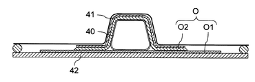
- the composite material structure O having a hollow structure as illustrated in FIG. 1, the composite material structure O in which the hat-shaped elongated structure O2 is formed on the panel O1 is exemplified.
- the composite structure O having such a structure is mainly used as a wing structure or a fuselage structure of an aircraft.
- a reinforcing member having a long structure such as a rib or a stringer may be mentioned.
- lamination of sheet-like prepregs or sheet-like fibers for reinforcing member and panel O1, shaping of uncured resin for reinforcing member and panel O1, and reinforcing member and panel O1 can be co-cured to simultaneously heat and cure. That is, after assembling the reinforcing member and the panel O1 in an uncured state, bagging can be performed and heat curing can be performed simultaneously.
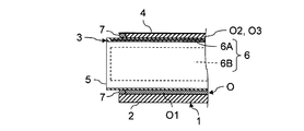
- the forming jig unit 1 is constituted by the forming die 2, the reinforced bladder bag 3 and the bagging film 4.
- the mold 2 is a rigid mold that supports the OML side of the panel O1.
- the surface on the OML side of the panel O1 is not limited to a flat surface and may be a curved surface with a small curvature. Therefore, the surface of the mold 2 has a substantially flat shape that matches the surface on the OML side of the panel O1 after molding.
- the mold 2 is a sheet-like prepreg or a laminate of fibers for the panel O1, a shaping on the OML side of the uncured resin for the panel O1, and a support with shape retention from the OML side at the time of heat curing of the panel O1.
- Used for The forming jig unit 1 is a jig unit that supports the OML side of the panel O1 with the forming die 2 and can be said to be a jig unit for the OML jig method.
- the reinforced bladder bag 3 is a partial inflatable mandrel that guides air to the inside and is used as a core jig. That is, the reinforced bladder bag 3 is used by being installed inside the composite structure O having a hollow structure. Therefore, the reinforced bladder bag 3 has a shape that fits inside the composite structure O having a hollow structure in the unfolded state.
- the reinforced bladder bag 3 includes a flexible tubular body 5 and at least one rigid plate embedded entirely in the tubular body 5 to partially reinforce the strength of the tubular body 5. Composed of six bodies. In the example shown in FIG. 1, three plate members 6 are inserted into the cylindrical member 5 in different directions with gaps in the direction perpendicular to the longitudinal direction of the cylindrical member 5.
- the tubular body 5 is made of the same material as the conventional bladder bag.
- the cylindrical body 5 can be made of an elastomer.
- the elastomer is a polymeric material having rubbery elasticity.
- the plate-like body 6 can be made of a composite material such as a metal or CFRP having sufficient mechanical strength to function as a rigid body.
- the plate-like body 6 is made of a composite material, it is possible to reduce the increase in weight of the reinforced bladder bag 3 accompanying the provision of the plate-like body 6 while securing the strength necessary for the plate-like body 6.
- the cylindrical body 5 in which the plate-like body 6 is embedded can be manufactured by arranging the plate-like body 6 at an appropriate position, and vulcanizing and molding an elastomer.
- the plurality of plate-like bodies 6 When a plurality of plate-like bodies 6 are embedded in the cylindrical body 5, the plurality of plate-like bodies 6 can be disposed with a gap in a direction perpendicular to the longitudinal direction of the cylindrical body 5. Thereby, while partial deformation of the cylindrical body 5 on the cross section of the cylindrical body 5 becomes possible, the deformation of the cylindrical body 5 on a plane parallel to the longitudinal direction of the cylindrical body 5 is suppressed. be able to. In other words, while the shape of the cross section of the cylindrical body 5 is deformed in a limited manner, rigidity can be imparted to the cylindrical body 5 on a plane parallel to the longitudinal direction of the cylindrical body 5.
- the reinforced bladder bag 3 has a hat-shaped cross section. It arrange
- the elongated structure O2 having a hat-shaped cross section has a structure in which two flat plate-shaped webs O4 are closed by a flat plate-shaped cap O3. Therefore, in the case where a composite material structure O in which the cross section has a hat-shaped long structure O2 formed on the panel O1 is a forming target, the composite material structure O during curing is the inner side of the long structure O2. As illustrated in FIG. 1, the first plate-like body 6A and the two second plate-like bodies 6B can be embedded in the inside of the cylindrical body 5 so as to support from the above.
- the first plate-like member 6A is a plate-like member 6 for reinforcing the strength of the portion of the tubular member 5 supporting the cap O3 of the long structure O2 from the inside.
- the two second plate-like members 6B are plate-like members 6 for respectively reinforcing the strength in the portion of the cylindrical member 5 which respectively supports the web O4 at two locations of the long structure O2 from the inside. It is. Therefore, the first plate-like body 6A is disposed at a position corresponding to the upper bottom of the R-chamfered isosceles trapezoid.
- the two second plate-like members 6B are respectively disposed at positions corresponding to the two legs of an isosceles trapezoidal R-chamfered trapezoid.
- the plate-like body 6 is not provided on the portion of the cylindrical body 5 fitted from the inside to the R-chamfer of the long structure O2 and the panel O1 side of the cylindrical body 5. That is, the portion of the reinforced bladder bag 3 supporting the R-chamfering of the long structure O2 from the inside and the portion of the reinforced bladder bag 3 on the panel O1 side are not reinforced by the plate-like body 6 and are composed of only the elastomer. .
- the reinforced bladder bag 3 can be deformed according to the deformation at the time of heat curing of the long structure O2.
- the reinforced bladder bag 3 since the plate-like body 6 is not inserted into the portion on the panel O1 side, after the heating and curing of the composite structure O, the reinforced bladder bag 3 may be bent inward to be easily pulled out from the inside of the long structure O2. It is possible.
- the shape of the long structure O2 can be held before and after heat curing. That is, the fibers impregnated with the uncured resin can be shaped into the shape of the long structure O2 by the reinforcing bladder bag 3 reinforced with the plate-like body 6 without using a rigid molding die. Furthermore, the shaped uncured resin can then be heat cured while maintaining its shape.
- the bagging film 4 is a film for performing bagging before the heat curing of the composite structure O.
- the bagging film 4 is attached to the mold 2 and the cylindrical body 5 of the reinforced bladder bag 3 with a sealant 7.
- the area covered by the bagging film 4 is depressurized by a vacuum device 8 equipped with a vacuum pump.
- FIG. 2 is a perspective view showing the structure at the end of the reinforced bladder bag 3 shown in FIG.
- the length of the reinforced bladder bag 3 is determined to be longer than the length of the long structure O2. Also, the length of the reinforced bladder bag 3 is determined so as to project beyond the edge of the panel O1. This is to allow the bagging film 4 to be attached to the reinforced bladder bag 3 with the sealant 7 outside the uncured resin while opening the inside of the reinforced bladder bag 3 to the outside.
- the side surface of the reinforced bladder bag 3 does not necessarily have to be closed. This is because it is desirable to introduce heating air to the inside of the reinforced bladder bag 3 at the time of heat curing of the composite structure O. In addition, at the time of positioning of the reinforced bladder bag 3, it is desirable to insert the rigid positioning member 9 inside the reinforced bladder bag 3 in order to prevent deflection in the longitudinal direction of the reinforced bladder bag 3.
- the side surface of the reinforced bladder bag 3 may be closed, and a through hole for introducing air may be provided.
- the side surface of the reinforced bladder bag 3 may be closed by an openable lid.
- FIG. 3 is a longitudinal sectional view for explaining the sealing method at the end of the reinforced bladder bag 3 shown in FIG.
- the portion of the bagging film 4 covering the long structure O 2 before curing can be attached to the reinforced bladder bag 3 with the sealant 7.
- the portion of the bagging film 4 covering the panel O1 before curing can be attached to the mold 2 with the sealant 7.
- the gap formed between the reinforced bladder bag 3 and the mold 2 and corresponding to the thickness of the panel O1 can also be closed with the sealant 7.
- region covered with the bagging film 4 can be sealed and vacuum suction can be performed by the vacuum apparatus 8.
- FIG. 1 shows an example in which the composite material structure O in which the transverse cross section has a hat-shaped long structure O2 formed on the panel O1 is a forming object, but it is a two-dimensional closed surface.
- the reinforced bladder bag 3 can be used for forming processes intended for various composite structures having a hollow structure to be formed.
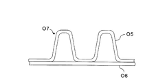
- FIG. 4 is a cross-sectional view showing an example of a composite structure O7 configured by attaching to the panel O6 a corrugated stringer O5 which can be formed by using the reinforced bladder bag 3 shown in FIG. 1 as a core jig.
- FIG. 4 is a cross-sectional view showing an example of a composite structure O7 configured by attaching to the panel O6 a corrugated stringer O5 which can be formed by using the reinforced bladder bag 3 shown in FIG. 1 as a core jig.
- FIG. 4 is a cross-sectional view showing an example of a composite structure O7 configured by attaching to the panel O6 a corrugated stringer O5 which can be formed by using the reinforced bladder bag 3 shown in FIG. 1 as a core jig.
- FIG. 4 is a cross-sectional view showing an example of a composite structure O7 configured by attaching to the panel O6 a corrugated stringer O5 which can be formed by using the reinforced bladder bag 3 shown in FIG. 1 as
- a composite material structure O7 configured by attaching to a panel O6 a corrugated stringer O5 having a corrugated structure in which a plurality of reinforcing members whose cross sections are hat-shaped are connected is a plurality of reinforced bladder bags 3 It can be molded using That is, the composite material structure O7 can be heat-hardened in a state in which the reinforcement-included bladder bag 3 is placed in a plurality of spaces surrounded by the closed curved surface formed between the corrugated stringer O5 and the panel O6.
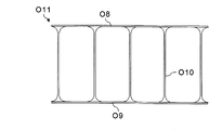
- FIG. 5 shows a composite structure having a structure in which an upper panel O8 and a lower panel O9 can be formed by using the reinforced bladder bag 3 shown in FIG. 1 as a core jig by a plurality of stringers O10. It is a cross-sectional view which shows the example of the body O11.
- a composite material structure O11 having a structure in which an upper panel O8 and a lower panel O9 are connected by a plurality of stringers O10 as shown in FIG. 5 can be formed using a plurality of reinforced bladder bags 3. That is, the composite structure O11 is heat-cured in a state in which the reinforcement-containing bladder 3 is placed in the space surrounded by the closed surface, which is formed between the upper panel O8, the lower panel O9 and two adjacent stringers O10. can do.
- the shape of the cross section of the stringer O10 is not limited to an I shape, but is arbitrary.
- FIG. 6 is a flowchart showing a first example of a method of forming the composite material structure O using the forming jig unit 1 shown in FIG.
- step S1 a sheet-like prepreg P1 for the panel O1 is stacked on the mold 2.
- step S2 a sheet-like prepreg P2 for the long structure O2, which is a reinforcing member of the panel O1, is stacked on the reinforcing bladder bag 3.
- the prepreg P1 for the panel O1 and the prepreg P2 for the long structure O2 can be respectively laminated on the mold 2 and the reinforced bladder bag 3 by an automatic laminating apparatus. Alternatively, the operator may manually laminate the prepreg P1 for the panel O1 and the prepreg P2 for the long structure O2.
- the reinforced bladder bag 3 on which the prepreg P2 for the long structure O2 is laminated is partially reinforced by the plate-like body 6.
- the strength at the portion of the cylindrical body 5 supporting the cap O3 of the long structure O2 from the inside is reinforced by the first plate-like body 6A.
- the strength in the part of the cylindrical body 5 which respectively supports the web O4 of two places of the elongate structure O2 from the inside is reinforced by the 2nd 2nd plate-like body 6B.
- a laminate of the prepreg P2 for the long structure O2 may be shaped by using a rigid jig such as the positioning member 9 in combination.
- step S3 the reinforced bladder bag 3 in which the sheet-like prepreg P2 for the long structure O2 is laminated is placed on the sheet-like prepreg P1 for the laminated panel O1.
- the sheet-like prepreg P2 for the long structure O2 may be laminated on the reinforced bladder bag 3 after the reinforced bladder bag 3 is placed on the sheet-like prepreg P1 for the panel O1. Good. However, if the prepreg P1 for the panel O1 and the prepreg P2 for the long structure O2 are separately laminated and then assembled, the working time is shortened.
- the prepreg P2 for the long structure O2 is placed on a rigid mold for the long structure O2.
- the laminated body of the prepreg P2 for the long structure O2 may be placed on the reinforced bladder bag 3 after laminating and shaping.
- the preform (uncured composite material) for the long structure O2 may be shaped not by the reinforced bladder bag 3 but by another rigid jig. In this case, since the preform for the long structure O2 is shaped by a rigid jig, a high quality preform can be manufactured.
- the reinforced bladder bag 3 has an elongated structure and is flexible. Therefore, when the length of the reinforced bladder bag 3 is long, bending occurs when the reinforced bladder bag 3 is transported by a hoist even if it is reinforced by the plate-like body 6. In particular, it is difficult to transport and position the reinforced bladder bag 3 in a state in which the prepreg P2 for the long structure O2 is stacked while maintaining the shape of the laminate of the prepreg P2 for the long structure O2.
- the positioning member 9 may be inserted in advance into the inside of the reinforced bladder bag 3 before laminating the prepreg P2 for the long structure O2, or the reinforced bladder bag after laminating the prepreg P2 for the long structure O2. You may insert in the inside of 3.
- the rigidity of the reinforced bladder bag 3 at the time of the lamination of the prepreg P2 for the long structure O2. Can be secured further. That is, the rigidity of the reinforced bladder bag 3 can be maintained to the same degree as that of the rigid body. For this reason, in the case of forming a preform for the long structure O2 using the reinforcement-containing bladder 3, it is similar to the case where the preform for the long structure O2 is formed using a rigid mold. It is possible to produce a preform for the long structure O2 with quality.
- the shape of the positioning member 9 is similar to the shape of the space formed inside the reinforced bladder bag 3 so as to appropriately restrain the deflection of the reinforced bladder bag 3 and to be able to be pulled out from the reinforced bladder bag 3. Is appropriate. Therefore, the structure of the positioning member 9 is a long structure, and is an isosceles trapezoid in which four corners are rounded. In addition, it is appropriate for the size of the outer surface of the positioning member 9 to provide a clearance for the size of the inner surface of the reinforcing bladder bag 3 so that the positioning member 9 can be easily pulled out from the reinforced bladder bag 3 .
- bagging is performed in step S4. Specifically, the sheet-like prepreg P1 for the laminated panel O1 and the sheet-like prepreg P2 for the long structure O2 are covered with the bagging film 4. However, the laminated body of the prepreg P1 for the panel O1 and the laminated body of the prepreg P2 for the long structure O2 are covered with the bagging film 4 so that the inside of the reinforced bladder bag 3 is opened to the outside without being sealed.
- the vacuum device 8 is driven to discharge the air from the area covered with the bagging film 4. That is, the area covered by the bagging film 4 is depressurized by the vacuum device 8. As a result, a differential pressure between the atmospheric pressure applied from the outside of the bagging film 4 and the vacuum pressure in the area covered by the bagging film 4 is applied to the area covered with the bagging film 4.
- the pressure is atmospheric pressure. Therefore, the atmospheric pressure loaded from the outside of the reinforced bladder bag 3 through the laminate of the bagging film 4 and the prepreg P2 for the long structure O2 is loaded from the inside of the reinforced bladder bag 3 to the reinforced bladder bag 3 It will be balanced with the atmospheric pressure. Moreover, the flat portions of the reinforced bladder bag 3 fitted to the cap O3 and the web O4 of the long structure O2 before curing are reinforced by the first plate 6A and the second plate 6B, respectively. . As a result, the shape of the laminate of the prepreg P2 for the long structure O2 can be held by the reinforced bladder bag 3 according to the shape of the long structure O2 after molding, before and after bagging.
- step S5 the laminate of the prepreg P1 for the panel O1 and the laminate of the prepreg P2 for the long structure O2 after bagging, that is, an uncured thermosetting resin reinforced with sheet-like fibers It is heat cured.
- the laminated body of the prepreg P1 for the panel O1 and the laminated body of the prepreg P2 for the long structure O2 after bagging are carried into an oven or an autoclave apparatus together with the mold 2 and the reinforced bladder bag 3.
- the composite which attached the elongate structure O2 to the panel O1 by heating the laminated body of the prepreg P1 for panel O1 under pressure, and the laminated body of the prepreg P2 for elongate structures O2 under pressure with an oven or an autoclave apparatus
- the material structure O is co-cure molded.
- the composite structure O undergoes a slight deformation associated with the heat curing.
- the reinforced bladder bag 3 is reinforced by the first plate 6A and the second plate 6B. It has flexibility except for flat portions on the cap O3 side and the web O4 side. Therefore, even if the composite material structure O including the long structure O2 is deformed due to heat curing, the reinforced bladder bag 3 can be fitted on the inner surface side of the long structure O2. Thereby, the composite material structure O which attached the cross-section long structure O2 of a hat type to the panel O1 can be manufactured with favorable quality.
- step S6 the composite structure O after the heat curing is carried out of the oven or the autoclave together with the mold 2 and the reinforced bladder bag 3. Then, the composite material structure O after the heating and curing is taken out from the forming jig unit 1 including the reinforced bladder bag 3.
- the reinforced bladder 3 is removed from the composite structure O after heat curing.
- the plate-like body 6 is not embedded in the side of the panel O1 of the tubular body 5 constituting the reinforcing bladder bag 3, the reinforcing bladder bag 3 can be easily deformed inward. For this reason, it is possible to easily pull out the reinforced bladder bag 3 from the inside of the long structure O2 after heat curing.
- the positioning member 9 for suppressing the bending of the reinforcing bag 3 can be pulled out of the reinforcing bag 3 after bagging or after heat curing.
- the composite forming method shown in FIG. 6 is a method of manufacturing a composite structure O having a hollow structure by laminating and heat curing a prepreg P1 for the panel O1 and a prepreg P2 for the long structure O2.
- the composite structure O having a hollow structure can also be manufactured by the VaRTM method.
- FIG. 7 is a flowchart showing a second example of a method of forming the composite material structure O using the forming jig unit 1 shown in FIG.
- step S10 the sheet-like fiber F1 for the panel O1 is laminated on the mold 2.
- step S11 the sheet-like fiber F2 for the long structure O2, which is a reinforcing member of the panel O1, is stacked on the reinforcing bladder bag 3.
- the fiber F1 for the panel O1 and the fiber F2 for the long structure O2 can be respectively laminated on the mold 2 and the reinforced bladder bag 3 by an automatic laminating apparatus.
- the worker may manually laminate the fiber F1 for the panel O1 and the fiber F2 for the long structure O2.
- it since there is no adhesive force between sheet-like fibers F2, it can be attached with a binder as needed.
- step S12 the reinforced bladder bag 3 in which the sheet-like fibers F2 for the long structure O2 are laminated is placed on the sheet-like fibers F1 for the laminated panel O1.
- the sheet fiber F2 for the long structure O2 is laminated on the reinforcing bladder bag 3 as well. Good. However, if the fiber F1 for the panel O1 and the fiber F2 for the long structure O2 are separately laminated and then assembled, the working time is shortened.
- the reinforced bladder sheet 3 is inserted in a state in which the rigid positioning member 9 for suppressing the deflection of the reinforced bladder bag 3 is inserted into the reinforced bladder bag 3. It is desirable from the viewpoint of placing the reinforced bladder bag 3 in a more accurate position, to be placed on the flat fiber.
- step S13 bagging is performed in step S13. Specifically, the sheet-like fibers F1 for the laminated panel O1 and the sheet-like fibers F2 for the long structure O2 are covered with the bagging film 4. However, the laminated body of the fiber F1 for the panel O1 and the laminated body of the fiber F2 for the long structure O2 are covered with the bagging film 4 so that the inside of the reinforced bladder bag 3 is opened to the outside without being sealed.
- the vacuum device 8 is driven to discharge the air from the area covered with the bagging film 4. That is, the area covered by the bagging film 4 is depressurized by the vacuum device 8. As a result, a differential pressure between the atmospheric pressure applied from the outside of the bagging film 4 and the vacuum pressure in the area covered by the bagging film 4 is applied to the area covered with the bagging film 4.
- step S14 an uncured thermosetting resin is injected into the area covered by the bagging film 4. That is, the uncured thermosetting resin is supplied from the resin storage tank 10 into the area covered with the bagging film 4. Thereby, the uncured thermosetting resin can be impregnated into the fiber F1 for the panel O1 and the fiber F2 for the long structure O2.
- the uncured thermosetting resin can be injected not only from the position where the fiber F1 for the panel O1 is laminated, but also from the position where the sheet-like fiber F2 for the long structure O2 is laminated. Then, the uncured resin can be quickly impregnated into the sheet-like fiber F2 for the long structure O2. As a result, the time required to impregnate the resin can be shortened.
- FIG. 7 shows an example in which fibers are supplied from both the position where the fiber F1 for the panel O1 is laminated and the position where the fiber F2 for the long structure O2 is laminated.
- the inside of the reinforced bladder bag 3 is not sealed by the bagging film 4 and thus the atmospheric pressure is obtained. Therefore, the atmospheric pressure loaded from the outside of the reinforced bladder bag 3 through the laminate of the bagging film 4 and the fiber F2 impregnated with the resin for the long structure O2 is the reinforced bladder bag from the inside of the reinforced bladder bag 3 It will be balanced with the atmospheric pressure loaded on 3. Moreover, the flat portions of the reinforced bladder bag 3 fitted to the cap O3 and the web O4 of the long structure O2 before curing are reinforced by the first plate 6A and the second plate 6B, respectively. .
- the shape of the laminate of fibers F2 impregnated with the resin for the long structure O2 can be shaped according to the shape of the long structure O2 after the molding. Moreover, the shape after shaping of the laminate of the fibers F2 impregnated with the resin for the long structure O2 can be held by the reinforced bladder bag 3.
- step S15 a laminate of fibers F1 impregnated with resin for panel O1 after bagging and injection of resin and a laminate of fibers F2 impregnated with resin for long structure O2, ie, sheet-like
- the fiber-reinforced uncured thermosetting resin is heat-cured.
- a laminate of fibers F1 impregnated with a resin for panel O1 and a laminate of fibers F2 impregnated with a resin for long structure O2 are the mold 2 and a mold. It is carried into the oven or the autoclave together with the reinforced bladder bag 3. Then, the laminate of the fibers F1 impregnated with the resin for the panel O1 under pressure and the laminate of the fibers F2 impregnated with the resin for the long structure O2 are heated by an oven or an autoclave apparatus, thereby obtaining a long film.
- the composite structure O having the structure O2 attached to the panel O1 is co-cured. Thereby, the composite material structure O which attached the cross-section long structure O2 of a hat type to the panel O1 can be manufactured with favorable quality.
- step S16 the composite structure O after heat curing is carried out of the oven or the autoclave together with the mold 2 and the reinforced bladder bag 3. Then, the composite material structure O after the heating and curing is taken out from the forming jig unit 1 including the reinforced bladder bag 3. At this time, as in step S6 of FIG. 6, the reinforcing bladder is inserted into the long structure O2 by deforming the side of the panel O1 not reinforced with the plate-like member 6 inward. It can be easily pulled out of the
- the hat-shaped elongated structure O2 is attached to the panel O1 by the hybrid molding method using the lamination of the prepreg and the VaRTM method in combination.
- the composite structure O can also be manufactured.
- a laminate of fibers F1 impregnated with a resin is manufactured by laminating a prepreg P1
- the elongated structure O2 is a fiber F2 impregnated with a resin by the VaRTM method.
- Laminates can be made.
- the composite structure having a desired hollow structure is manufactured not only by the composite structure O having the hat-shaped elongated structure O2 attached to the panel O1 but by the above-described composite forming method. Is possible.
- the composite material forming method as described above is such that a composite material structure having a hollow structure is formed by using the reinforced bladder bag 3 partially reinforced by the rigid plate 6 as a core jig. . That is, the reinforced bladder bag 3 retains the extensibility necessary for molding while providing the bladder bag with a shape retaining function.
- the structure of the jig is simplified as compared with the conventional one while securing the freedom of design when forming the composite material structure having the hollow structure.
- FIG. 8 is a view showing a method of forming a composite according to a conventional OML jig method in which a composite structure having a hat-shaped cross section is formed using a mandrel as a core jig.
- the OML side of the panel O1 is selected as one of the conventional composite material forming methods for manufacturing a composite material structure O in which the cross section has a hat-shaped long structure O2 attached to the panel O1.
- the shape of the composite structure O is limited to a shape that allows the mandrel 21 to be pulled out.
- the handling including the transfer of the mandrel 21 requires labor.
- the reinforced bladder bag 3 can be deformed, it can be easily pulled out from the inside of the long structure O2 after heat curing. For this reason, it is possible to secure the freedom of design of the composite structure having a hollow structure as well as the composite structure O in which the elongated cross section O2 is attached to the panel O1 in cross section. Moreover, since the reinforced bladder bag 3 is hollow, it is lightweight, and handling including transport is easy.
- FIG. 9 is a view showing a method for forming a composite material according to a conventional IML jig method, in which a composite material structure having a hat-shaped cross section is formed using upper and lower molds and a normal bladder bag.
- An IML of panel O1 as shown in FIG. 9 is one of the other conventional composite forming methods for fabricating a composite structure O in which a cross section has a hat-shaped elongated structure O2 attached to the panel O1.
- the composite material structure O is manufactured by the OML jig system using the reinforcement-included bladder bag 3, a mold having a complicated structure becomes unnecessary.
- the panel O1 can be stably supported by the rigid mold 2.
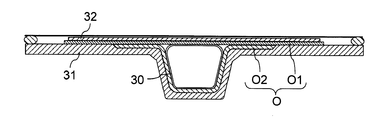
- FIG. 10 is a view showing a method of forming a composite according to a conventional OML jig method in which a composite structure having a hat-shaped cross section is formed using upper and lower molds and a normal bladder bag.
- FIG. 10 As shown in FIG. 10, as one of the conventional composite forming methods for manufacturing a composite structure O in which the cross section has a hat-shaped elongated structure O2 attached to the panel O1, as shown in FIG.
- the OML side is downward, and the bladder bag 40 without reinforcement is inserted inside the long structure O2 before curing, while the entire composite structure O before curing is called the IML side mold 41 called a cowl plate, the OML side There is a method of supporting the mold 42 from two directions.
- the cowl plate which is the IML side molding die 41 can be made unnecessary. That is, even if the cowl plate is not used, the reinforced bladder bag 3 is deformed into a cylindrical shape during heat curing of the composite structure O, or the cap O3 or the web O4 is dented or distorted due to the influence of gravity. Can be avoided.
- the jig conventionally placed on the atmosphere side can be omitted. For this reason, the labor and time required for placing, removing and cleaning the jig can be reduced.
- the weight of the composite structure O including the jig can be reduced. For this reason, not only conveyance becomes easy, but the volume of the object to be heated can be reduced. As a result, the time and energy required for the heat curing of the composite structure O can be reduced.
- the rigid body mold is not installed on the atmosphere side. Therefore, the pressure corresponding to the atmospheric pressure can be uniformly applied to the composite structure O during heat curing. As a result, the composite structure O can be manufactured with good quality.
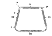
- FIG. 11 is a cross-sectional view showing the structure of a reinforced bladder bag which is a composite molding jig according to a second embodiment of the present invention.
- the point at which the third plate-like body 6C is embedded in the panel O1 side of the cylindrical body 5 constituting the reinforced bladder bag 3A is the first It differs from the forming jig unit 1 in the embodiment.
- the other configuration and operation of the forming jig unit 1A in the second embodiment are not substantially different from those of the forming jig unit 1 in the first embodiment, and therefore the same configuration or the corresponding configuration have the same reference numerals. The explanation is omitted.
- the first plate-like body 6A and the elongated structure on the cap O3 side of the elongated structure O2 whose cross-sectional shape is a hat type In addition to the two second plate-like members 6B on the web O4 side of the object O2, the third plate-like member 6C on the panel O1 side can be embedded. Then, the reinforced bladder bag 3A can be reinforced by the third plate-like body 6C also on the panel O1 side.
- the reinforced bladder bag 3A When the reinforced bladder bag 3A is reinforced with the third plate-like member 6C divided in this way, the reinforcement with the third bladder 6C partially reinforces the strength of the reinforced bladder bag 3A on the panel O1 side. It is possible to easily fold the bladder bag 3A on the panel O1 side. Therefore, the reinforced bladder bag 3A can be easily pulled out from the composite structure O after heat curing.
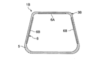
- FIG. 12 is a cross-sectional view showing the structure of a reinforced bladder bag which is a composite molding jig according to a third embodiment of the present invention.
- the point in which a part of the plate-like body 6 is embedded in the cylindrical body 5 constituting the reinforced bladder bag 3B is the forming according to the first embodiment. It differs from the jig unit 1.
- the other configuration and function of the forming jig unit 1B in the third embodiment are not substantially different from those of the forming jig unit 1 in the first embodiment, and only the reinforced bladder bag 3B is illustrated, and the same configuration or correspondence The same components are given the same reference numerals and the description thereof is omitted.
- the reinforced bladder bag 3 ⁇ / b> B can be configured by embedding only a part of the plate-like body 6 in the tubular body 5 without embedding the whole plate-like body 6 in the tubular body 5. Then, the plate-like body 6 can be replaced as needed. Therefore, for example, when the plate 6 is deformed or when using the plate 6 having different strength, the plate 6 can be easily replaced.
- the second embodiment instead of embedding the entire plate-like body 6 in the tubular body 5, a part of the plate-like body 6 can be embedded in the tubular body 5.
- FIG. 13 is a cross section showing the structure of a reinforced bladder bag which is a composite molding jig according to a fourth embodiment of the present invention.
- the forming in the first embodiment is that the plate 6 is attached to the inner surface of the cylindrical body 5 constituting the reinforced bladder bag 3C. It differs from the jig unit 1.
- the other configuration and operation of the forming jig unit 1C in the fourth embodiment are not substantially different from those of the forming jig unit 1 in the first embodiment, and only the reinforced bladder bag 3C is illustrated, and the same structure or corresponding The same components are given the same reference numerals and the description thereof is omitted.
- the reinforcing bladder is configured by sticking one surface of the plate 6 to the inner surface of the tube 5 with an adhesive without embedding the plate 6 in the tube 5. You can also. Then, not only can the plate-like body 6 be replaced as necessary, but it becomes possible to affix the plate-like body 6 to the existing bladder bag to produce the reinforced bladder bag 3C. Therefore, as in the third embodiment, for example, when the plate 6 is deformed or when the plate 6 having different strength is used, the plate 6 can be easily replaced or attached. it can. Of course, in the second embodiment, instead of embedding the plate-like body 6 in the tubular body 5, one surface of the plate-like body 6 may be attached to the inner surface of the tubular body 5.
Landscapes
- Engineering & Computer Science (AREA)
- Mechanical Engineering (AREA)
- Chemical & Material Sciences (AREA)
- Composite Materials (AREA)
- Architecture (AREA)
- Civil Engineering (AREA)
- Structural Engineering (AREA)
- Manufacturing & Machinery (AREA)
- Moulding By Coating Moulds (AREA)
- Casting Or Compression Moulding Of Plastics Or The Like (AREA)
- Moulds For Moulding Plastics Or The Like (AREA)
Abstract
実施形態に係る複合材成形治具3は、中空構造を有する複合材構造体O(O1、O2)を簡易に成形できるようにするものであり、内部に空気を導いて使用されるものである。この複合材成形治具3は、可撓性を有する筒状体5と、前記筒状体5の強度を部分的に補強する少なくとも1つの剛体の板状体6(6A、6B)とを有する。また、実施形態に係る複合材成形方法は、中空構造を有する複合材構造体O(O1、O2)を簡易に成形できるようにするものであり、上述した複合材成形治具3を用いて複合材構造体O(O1、O2)を製作するものである。
Description
本発明の実施形態は、複合材成形治具及び複合材成形方法に関する。
従来、航空機構造体を始めとする構造体の素材として、繊維で樹脂を強化したガラス繊維強化プラスチック(GFRP: Glass fiber reinforced plastics)や炭素繊維強化プラスチック(CFRP: Carbon Fiber Reinforced Plastics)等の複合材が用いられている。
複合材の成形方法としては、シート状の繊維に未硬化の熱硬化性樹脂を含浸させたプリプレグを積層し、プリプレグの積層体を成形後の形状に整えた後、真空引きを行って加熱硬化する方法と、成形後の複合材の形状に合わせてシート状の繊維を積層した後に真空引きを行って熱硬化性樹脂を含浸させて加熱硬化するRTM(Resin Transfer Molding)法が知られている。プリプレグは、オーブンやオートクレーブ装置で加熱硬化される。尚、プリプレグの形状を整える作業は、加熱硬化による複合材の成形と区別するために、賦形と呼ばれる。
プリプレグや繊維を積層して賦形を行うための治具としては、剛体の成形型やプラダバッグ等の様々な治具が考案されている。具体例として、外板(パネル)に桁(スパー)を取付けた航空機の翼構造体において桁のウェブを成形するための治具として、GFRPのプレートをシリコンゴムシートで連結することによって真空引きを可能にした形状保持具が提案されている(例えば特許文献1参照)。また、真空引きを行うための真空バッグとして、繰返し使用できるように柔軟性のあるダイヤフラム内に剛体のフレームを封入したものが提案されている(例えば特許文献2参照)。
他方、航空機の部品等として使用される複合材のフレームを成形する方法として、金属製の外型、合成樹脂製又はゴム製の内型並びにゴム等の可撓性を有する合成樹脂で形成された管状の中子を使用し、RTM法によってフレームを成形する方法も提案されている(例えば特許文献3参照)。
航空機の翼構造体や胴体構造体には、長尺構造を有する補強部材をパネルに取付けた複合材構造体が採用される。パネルの補強部材としては、スパーの他、小骨(リブ)や縦通材(ストリンガ)が挙げられる。パネルに補強部材を取付けた複合材構造体は、部品の組立作業に伴う製造コスト及び製造時間の増加を抑制することを目的として、近年では部品ごとに加熱硬化せずに、コキュア成形によって製造される。コキュア成形は、補強部材とパネルを同時に加熱硬化する成形法である。
コキュア成形によって補強部材をパネルに取付けた複合材構造体を成形する場合には、補強部材用のプリプレグの積層体及びパネル用のプリプレグの積層体がそれぞれ製作され、プリプレグの積層体を組立てた後、加熱硬化することによって複合材構造体が製造される。或いは、パネルに補強部材を形成した一体型のプリプレグの積層体を製作して加熱硬化する場合もある。
パネルに取付けられる補強部材の横断面がハット型である場合には、複合材構造体が中空構造となる。このため、未硬化の樹脂を含浸した繊維を、中空構造に賦形することが必要となる。そこで、未硬化の樹脂を含浸した繊維を中空構造に賦形した後、真空引きを行って加熱硬化するための様々な成形治具が用いられている。
横断面がハット型の補強部材をパネルに取付けた航空機用の複合材構造体を成形するための従来の方法は、補強部材が設けられない側のパネルの表面、すなわちパネルのOML(outer mold line)側に剛体の型を設置する一方、補強部材が設けられる側のパネルの表面、すなわちパネルのIML(inner mold line)側をバギングして大気圧を負荷するOML治具方式と、逆に、パネルのIML側に剛体の型を設置する一方、パネルのOML側をバギングして大気圧を負荷するIML治具方式に大別される。
IML治具方式で中空構造を有する複合材構造体を成形する方法の具体例としては、パネル用の樹脂と、補強部材用の樹脂との間、すなわち補強部材の内側にブラダバッグを配置する方法が知られている(例えば特許文献4参照)。ブラダバッグは、エラストマで構成されるバッグであり、空気を注入して使用されるインフレータブルマンドレルの1つである。IML治具方式においても、精度を維持するためにパネルのOML側に剛体のプレートを設置した上でバギングを行うことが必要となる。
一方、OML治具方式で中空構造を有する複合材構造体を成形する方法の具体例としては、パネル用の樹脂と、補強部材用の樹脂との間、すなわち補強部材の内側に中実のマンドレルを中子治具として設置する方法が挙げられる(例えば特許文献5参照)。また、OML治具方式において、補強部材の内側に熱硬化性樹脂で構成される中空のインナー部材を配置し、加熱硬化によってインナー部材を補強部材と一体化する方法が提案されている(例えば特許文献6参照)。
しかしながら、IML治具方式の場合には、補強部材の形状に合わせた成形型が必要となる。このため、複雑な構造を有する成形型を製作することが必要になるという課題がある。また、パネル用のプリプレグがブラダバッグの上に積層されることになる。このため、パネルを平坦に保つことが困難となる恐れがある。換言すれば、パネル用のプリプレグの積層体を支持できるようにブラダバッグの弾性及び強度を設計することが必要となる。加えて、上下の剛体の成形型で未硬化の樹脂を挟むことになるため、大気圧を負荷したとしても圧力が不均一になるという問題がある。
一方、補強部材の内側にマンドレルを中子治具として設置するOML治具方式の場合には、複合材の硬化後において剛体のマンドレルを引き抜くことが必要となる。このため、複合材の形状が、マンドレルを引き抜くことが可能な形状に限定される。加えて、マンドレルの重量も、引き抜くことが可能な重量に制限されることになる。特に、重量が大きなマンドレルを設置した場合には、マンドレルの引き抜き作業に時間と労力を要する。
他方、補強部材の内側に中空のインナー部材を配置して補強部材と一体化するOML治具方式の場合には、補強部材の外側に剛体の成形型としてカウルプレートを設置することが必要となる。
また、仮に、補強部材の内側に中空のインナー部材に代えてブラダバッグを配置したとしても、ブラダバッグ自体に形状を保持する機能が無いことから、複合材の加熱硬化中においてブラダバッグが理想的な形状から変形してしまう。このため、補強部材の内側にブラダバッグを配置する場合においても、補強部材の外側に剛体の成形型としてカウルプレートを設置することが必要となる。その結果、治具の構成が複雑となるのみならず、IML治具方式と同様に、上限の剛体の成形型で未硬化の樹脂を挟むことになるため、大気圧を負荷したとしても圧力が不均一になるという問題がある。
そこで、本発明は、中空構造を有する複合材構造体を簡易に成形できるようにすることを目的とする。
本発明の実施形態に係る複合材成形治具は、内部に空気を導いて使用され、可撓性を有する筒状体と、前記筒状体の強度を部分的に補強する少なくとも1つの剛体の板状体とを有する。
また、本発明の実施形態に係る複合材成形方法は、上述した複合材成形治具を用いて複合材構造体を製作するものである。
本発明の実施形態に係る複合材成形治具及び複合材成形方法について添付図面を参照して説明する。
(第1の実施形態)
(複合材成形治具の構成及び機能)
図1は本発明の第1の実施形態に係る複合材成形治具である補強入りブラダバッグを含む成形治具ユニットの構造を示す横断面である。
(複合材成形治具の構成及び機能)
図1は本発明の第1の実施形態に係る複合材成形治具である補強入りブラダバッグを含む成形治具ユニットの構造を示す横断面である。
成形治具ユニット1は、2次元的な閉曲面を有する中空の複合材構造体Oを成形するための治具である。すなわち、成形治具ユニット1は、シート状の繊維束に熱硬化性樹脂を含浸させた硬化前におけるプリプレグの積層、積層されたプリプレグの賦形及びプリプレグの積層体の加熱硬化を行うための治具である。
尚、シート状の繊維を積層した後に熱硬化性樹脂を含浸させるようにしてもよい。その場合には、シート状のプリプレグに代えて、シート状の繊維が成形治具ユニット1を用いて積層される。繊維を積層した後に樹脂を含浸させる複合材の成形方法は、上述したようにRTM法と呼ばれる。RTM法のうち、真空圧で繊維に樹脂を含浸させる手法は、VaRTM(Vacuum assisted Resin Transfer Molding)法と呼ばれる。
また、プリプレグの積層と、RTM法を併用するハイブリッド成形法による複合材の成形用に成形治具ユニット1を用いることもできる。ハイブリッド成形法は、プリプレグの積層体の上にシート状の繊維を積層し、積層されたシート状の繊維に樹脂を含浸させた後、加熱硬化する複合材の成形法である。従って、ハイブリッド成形法による複合材の成形用に成形治具ユニット1が用いられる場合には、シート状のプリプレグ及びシート状の繊維の双方が積層されることになる。
複合材を加熱硬化する方法としては、任意の方法を採用することができる。複合材の典型的な加熱硬化法としては、オートクレーブ成形装置内に硬化前の複合材を搬入し、真空引きを行って加圧下で加熱硬化する方法が挙げられる。一方、オートクレーブ成形装置を使用せずに複合材を成形する様々な脱オートクレーブ(OoA:Out of autoclave)成形法が知られている。具体例として、オーブンで複合材を加熱硬化する方法が知られている。従って、複合材の加熱硬化法に応じた所望の設備内に、硬化前かつ賦形後の複合材をセットした成形治具ユニット1を搬入することができる。
複合材構造体Oを構成する素材の例としては、CFRPやGFRP等の炭素繊維やガラス繊維で樹脂を強化した複合材が代表的である。また、中空構造を有する複合材構造体Oの例としては、図1に例示されるようにパネルO1上に、横断面がハット型の長尺構造物O2を形成した複合材構造体Oが挙げられる。このような構造を有する複合材構造体Oは、主に航空機の翼構造体や胴体構造体として用いられる。横断面がハット型の長尺構造物O2の例としては、リブやストリンガ等の長尺構造を有する補強部材が挙げられる。
成形治具ユニット1を用いると、補強部材用とパネルO1用のシート状のプリプレグ又はシート状の繊維の積層、補強部材用とパネルO1用の未硬化の樹脂の賦形並びに補強部材とパネルO1を同時に加熱硬化するコキュア成形を行うことができる。つまり、補強部材及びパネルO1を未硬化の状態で組立てた後、バギングを行って同時に加熱硬化することができる。
そのために、成形治具ユニット1は、成形型2、補強入りブラダバッグ3及びバギングフィルム4で構成される。
成形型2は、パネルO1のOML側を支持する剛体の型である。パネルO1のOML側の表面は平面に限らず曲率が小さな曲面であってもよい。従って、成形型2の表面は、成形後におけるパネルO1のOML側の表面とマッチする略平坦な形状を有する。成形型2は、パネルO1用のシート状のプリプレグ又は繊維の積層、パネルO1用の未硬化の樹脂のOML側における賦形並びにパネルO1の加熱硬化時におけるOML側からの形状保持を伴う支持のために用いられる。成形治具ユニット1は、パネルO1のOML側を成形型2で支持する治具ユニットであるためOML治具方式用の治具ユニットであると言うことができる。
補強入りブラダバッグ3は、内部に空気を導いて中子治具として使用される部分的なインフレータブルマンドレルである。すなわち、補強入りブラダバッグ3は、中空構造を有する複合材構造体Oの内側に設置して使用される。従って、補強入りブラダバッグ3は、広げた状態で、中空構造を有する複合材構造体Oの内側にフィットする形状を有する。
補強入りブラダバッグ3は、可撓性を有する筒状体5と、筒状体5の強度を部分的に補強するために筒状体5の内部に全体が埋め込まれた少なくとも1つの剛体の板状体6で構成される。図1に示す例では、3枚の板状体6が筒状体5の内部に筒状体5の長さ方向に垂直な方向に隙間をあけて異なる向きで挿入されている。
筒状体5は、従来のブラダバッグと同じ素材で構成される。具体的には、筒状体5は、エラストマで構成することができる。エラストマは、ゴム状弾性を有する高分子材料である。一方、板状体6は、剛体として機能するように十分な機械的強度を有する金属やCFRP等の複合材で構成することができる。特に、板状体6を複合材で構成すれば、板状体6に必要な強度を確保しつつ板状体6を設けることに伴う補強入りブラダバッグ3の重量の増加を軽減することができる。内部に板状体6を埋め込んだ筒状体5は、板状体6を適切な位置に配置し、エラストマを加硫及び成型することによって製造することができる。
筒状体5に複数の板状体6を埋め込む場合には、複数の板状体6を、筒状体5の長さ方向に垂直な方向に隙間をあけて配置することができる。これにより、筒状体5の横断面上における筒状体5の部分的な変形が可能となる一方、筒状体5の長さ方向に平行な平面上における筒状体5の変形を抑止することができる。換言すれば、筒状体5の横断面の形状を限定的に変形させる一方、筒状体5の長さ方向に平行な平面上において筒状体5に剛性を付与することができる。
図1に示すように、横断面がハット型の長尺構造物O2をパネルO1上に形成した複合材構造体Oが成形対象である場合には、補強入りブラダバッグ3は、横断面がハット型の長尺構造物O2の内側に配置して中子治具として使用される。このため、筒状体5の横断面の形状もハット型の長尺構造物O2の内側にフィットする形状、具体的には4つの頂点にR面取りを施した等脚台形とされる。
横断面がハット型の長尺構造物O2は、平坦な板状のキャップO3でそれぞれ平坦な板状の2箇所のウェブO4を閉塞した構造を有する。そこで、横断面がハット型の長尺構造物O2をパネルO1上に形成した複合材構造体Oが成形対象である場合には、硬化中における複合材構造体Oを長尺構造物O2の内側から支持できるように、図1に例示されるように第1の板状体6Aと、2枚の第2の板状体6Bとを筒状体5の内部に埋め込むことができる。
第1の板状体6Aは、長尺構造物O2のキャップO3を内側から支持する筒状体5の部分における強度を補強するための板状体6である。一方、2枚の第2の板状体6Bは、それぞれ長尺構造物O2の2箇所のウェブO4を内側からそれぞれ支持する筒状体5の部分における強度をそれぞれ補強するための板状体6である。従って、第1の板状体6Aは、R面取りを施した等脚台形の上底に対応する位置に配置される。一方、2枚の第2の板状体6Bは、R面取りを施した等脚台形の2本の脚に対応する位置にそれぞれ配置される。
他方、長尺構造物O2のR面取りに内側からフィットさせる筒状体5の部分と、筒状体5のパネルO1側には、板状体6が設けられない。すなわち、長尺構造物O2のR面取りを内側から支持する補強入りブラダバッグ3の部分と、補強入りブラダバッグ3のパネルO1側の部分は、板状体6で補強されずにエラストマのみで構成される。
このため、エラストマの伸展性により補強入りブラダバッグ3の板状体6が設けられない部分を、複合材構造体Oの加熱硬化時における形状の変化に追従させることが可能である。すなわち、長尺構造物O2の加熱硬化時における変形に合わせて補強入りブラダバッグ3を変形させることができる。また、パネルO1側の部分に板状体6が挿入されないため、複合材構造体Oの加熱硬化後には、補強入りブラダバッグ3を内側に折り曲げて容易に長尺構造物O2の内側から引き抜くことが可能である。
このような構成を有する補強入りブラダバッグ3を中子治具として用いると、長尺構造物O2の形状を、加熱硬化前後に亘って保持することができる。すなわち、剛体の成型型を用いることなく、未硬化の樹脂を含浸させた繊維を、板状体6で補強された補強入りブラダバッグ3で長尺構造物O2の形状に賦形することができる。更に、その後、賦形された未硬化の樹脂を、形状を保持しながら加熱硬化することができる。
バギングフィルム4は、複合材構造体Oの加熱硬化前におけるバギングを行うためのフィルムである。バギングフィルム4は、シーラント7で成形型2及び補強入りブラダバッグ3の筒状体5に貼り付けられる。バギングフィルム4で覆われた領域は、真空ポンプを備えた真空装置8で減圧される。
図2は、図1に示す補強入りブラダバッグ3の端部における構造を示す斜視図である。
図2に示すように補強入りブラダバッグ3の長さは、長尺構造物O2の長さよりも長くなるように決定される。また、補強入りブラダバッグ3の長さは、パネルO1の縁よりも突出する長さに決定される。これは、補強入りブラダバッグ3の内部を外部に開放しつつ、未硬化の樹脂の外側においてバギングフィルム4をシーラント7で補強入りブラダバッグ3に貼り付けることができるようにするためである。
補強入りブラダバッグ3の側面は必ずしも閉塞する必要がない。これは、複合材構造体Oの加熱硬化時において補強入りブラダバッグ3の内部に加熱用の空気を導くことが望ましいためである。加えて、補強入りブラダバッグ3の位置決め時には、補強入りブラダバッグ3の長さ方向における撓みを抑止するために、補強入りブラダバッグ3の内部に剛体の位置決め部材9を挿入することが望ましいためである。
但し、強度を得るために補強入りブラダバッグ3の側面を閉塞し、空気を導くための貫通孔を設けるようにしてもよい。また、開閉式の蓋で補強入りブラダバッグ3の側面を閉塞するようにしてもよい。
図3は、図1に示す補強入りブラダバッグ3の端部におけるシール方法を説明する縦断面図である。
図3に示すように硬化前における長尺構造物O2を覆うバギングフィルム4の部分をシーラント7で補強入りブラダバッグ3に貼り付けることができる。また、硬化前におけるパネルO1を覆うバギングフィルム4の部分をシーラント7で成形型2に貼り付けることができる。更に、補強入りブラダバッグ3と成形型2との間に形成される、パネルO1の厚さに相当する隙間も、シーラント7で塞ぐことができる。
これにより、バギングフィルム4で覆われた領域を密閉し、真空装置8で真空引きを行うことができる。すなわち、バギングフィルム4で覆われた領域から空気を排出することによって、硬化前後の樹脂に大気圧を作用させることができる。
尚、図1は、横断面がハット型の長尺構造物O2をパネルO1上に形成した複合材構造体Oが成形対象である場合の例を示しているが、2次元的な閉曲面で形成される中空構造を有する様々な複合材構造体を対象とする成形加工用に補強入りブラダバッグ3を用いることができる。
図4は、図1に示す補強入りブラダバッグ3を中子治具として用いることによって成形することが可能なコルゲートストリンガO5をパネルO6に取付けて構成される複合材構造体O7の例を示す横断面図である。
図4に示すように横断面がハット型である複数の補強部材を連結した波型構造を有するコルゲートストリンガO5をパネルO6に取付けて構成される複合材構造体O7を、複数の補強入りブラダバッグ3を用いて成形することができる。すなわち、コルゲートストリンガO5とパネルO6との間に形成される、閉曲面で囲まれた複数の空間にそれぞれ補強入りブラダバッグ3を載置した状態で複合材構造体O7を加熱硬化することができる。
図5は、図1に示す補強入りブラダバッグ3を中子治具として用いることによって成形することが可能な上側パネルO8と下側パネルO9とを複数のストリンガO10で連結した構造を有する複合材構造体O11の例を示す横断面図である。
図5に示すように上側パネルO8と下側パネルO9とを複数のストリンガO10で連結した構造を有する複合材構造体O11を、複数の補強入りブラダバッグ3を用いて成形することができる。すなわち、上側パネルO8、下側パネルO9及び隣接する2つのストリンガO10の間に形成される、閉曲面で囲まれた空間に補強入りブラダバッグ3を載置した状態で複合材構造体O11を加熱硬化することができる。尚、ストリンガO10の横断面の形状はI字型に限らず任意である。
(複合材成形治具を用いた複合材成形方法)
次に補強入りブラダバッグ3を含む成形治具ユニット1を用いて2次元的な閉曲面を有する中空の複合材構造体Oを製作する複合材成形方法について説明する。
次に補強入りブラダバッグ3を含む成形治具ユニット1を用いて2次元的な閉曲面を有する中空の複合材構造体Oを製作する複合材成形方法について説明する。
図6は、図1に示す成形治具ユニット1を用いて複合材構造体Oを成形する方法の第1の例を示すフローチャートである。
まずステップS1において、成形型2にパネルO1用のシート状のプリプレグP1が積層される。他方、ステップS2において、補強入りブラダバッグ3にパネルO1の補強部材である長尺構造物O2用のシート状のプリプレグP2が積層される。パネルO1用のプリプレグP1及び長尺構造物O2用のプリプレグP2は、自動積層装置によって成形型2及び補強入りブラダバッグ3上にそれぞれ積層することができる。或いは、作業者が手作業でパネルO1用のプリプレグP1及び長尺構造物O2用のプリプレグP2を積層するようにしてもよい。
長尺構造物O2用のプリプレグP2が積層される補強入りブラダバッグ3は、板状体6で部分的に補強されている。具体的には、長尺構造物O2のキャップO3を内側から支持する筒状体5の部分における強度が第1の板状体6Aで補強されている。また、長尺構造物O2の2箇所のウェブO4を内側からそれぞれ支持する筒状体5の部分における強度が、それぞれ2枚の第2の板状体6Bで補強されている。このため、補強入りブラダバッグ3に長尺構造物O2用のプリプレグP2を積層するのみで、長尺構造物O2用のプリプレグP2の積層体を、長尺構造物O2の形状に合わせて賦形することができる。
但し、後述するように、位置決め部材9等の剛体の治具を併用して長尺構造物O2用のプリプレグP2の積層体を賦形するようにしてもよい。
次に、ステップS3において、積層されたパネルO1用のシート状のプリプレグP1の上に、長尺構造物O2用のシート状のプリプレグP2が積層された補強入りブラダバッグ3が載置される。
尚、補強入りブラダバッグ3をパネルO1用のシート状のプリプレグP1の上に載置した後に、長尺構造物O2用のシート状のプリプレグP2を補強入りブラダバッグ3の上に積層するようにしてもよい。但し、パネルO1用のプリプレグP1及び長尺構造物O2用のプリプレグP2を別々に積層してから組立てるようにすれば、作業時間の短縮に繋がる。
また、パネルO1用のプリプレグP1と、長尺構造物O2用のプリプレグP2を別々に積層する場合には、長尺構造物O2用の剛体の型の上に長尺構造物O2用のプリプレグP2を積層して賦形した後、長尺構造物O2用のプリプレグP2の積層体を補強入りブラダバッグ3の上に載置するようにしてもよい。換言すれば、長尺構造物O2用のプリフォーム(未硬化の複合材)を補強入りブラダバッグ3ではなく、別の剛体の治具で賦形するようにしてもよい。この場合、長尺構造物O2用のプリフォームは剛体の治具で賦形されるため、高品質なプリフォームを製作することができる。
補強入りブラダバッグ3は長尺構造を有し、かつ可撓性を有する。このため補強入りブラダバッグ3の長さが長い場合には、板状体6で補強しても補強入りブラダバッグ3をホイスト等で搬送する際には撓みが生じる。特に、長尺構造物O2用のプリプレグP2が積層された状態の補強入りブラダバッグ3を、長尺構造物O2用のプリプレグP2の積層体の形状を保ちながら搬送及び位置決めすることは困難である。
そこで、補強入りブラダバッグ3の内部に、補強入りブラダバッグ3の撓みを抑止するための剛体の位置決め部材9を挿入した状態で補強入りブラダバッグ3をシート状のプリプレグP1の上に載置することが、補強入りブラダバッグ3をより正確な位置に載置する観点から望ましい。位置決め部材9は、長尺構造物O2用のプリプレグP2の積層前において予め補強入りブラダバッグ3の内部に挿入しておいても良いし、長尺構造物O2用のプリプレグP2の積層後に補強入りブラダバッグ3の内部に挿入しても良い。
長尺構造物O2用のプリプレグP2の積層前に位置決め部材9を補強入りブラダバッグ3の内部に挿入しておけば、長尺構造物O2用のプリプレグP2の積層時において、補強入りブラダバッグ3の剛性を一層確保することができる。すなわち、補強入りブラダバッグ3の剛性を剛体の型と同程度に保つことができる。このため、補強入りブラダバッグ3を用いて長尺構造物O2用のプリフォームを賦形する場合において、剛体の型を用いて長尺構造物O2用のプリフォームを賦形する場合と同程度の品質で、長尺構造物O2用のプリフォームを製作することが可能となる。
位置決め部材9の形状は、補強入りブラダバッグ3の撓みを適切に抑止し、かつ補強入りブラダバッグ3から引き抜くことができるように補強入りブラダバッグ3の内側に形成される空間の形状と同様な形状とすることが適切である。従って、位置決め部材9の構造は長尺構造となり、4つの頂点にR面取りを施した等脚台形となる。また、位置決め部材9を補強入りブラダバッグ3から容易に引き抜くことができるように、位置決め部材9の外表面のサイズには、補強入りブラダバッグ3の内面のサイズに対してクリアランスを設けることが適切である。
パネルO1用のプリプレグP1の積層体と長尺構造物O2用のプリプレグP2の積層体の組立が完了すると、ステップS4において、バギングが行われる。具体的には、積層されたパネルO1用のシート状のプリプレグP1及び長尺構造物O2用のシート状のプリプレグP2がバギングフィルム4で覆われる。但し、補強入りブラダバッグ3の内部が密閉されずに外部に開放されるようにパネルO1用のプリプレグP1の積層体及び長尺構造物O2用のプリプレグP2の積層体がバギングフィルム4で覆われる。
そして、真空装置8が駆動し、バギングフィルム4で覆われた領域から空気が排出される。すなわち、バギングフィルム4で覆われた領域が真空装置8によって減圧される。これにより、バギングフィルム4で覆われた領域には、バギングフィルム4の外側から負荷される大気圧と、バギングフィルム4で覆われた領域内における真空圧との間における差圧が負荷される。
この時、補強入りブラダバッグ3の内側は、バギングフィルム4で密閉されないため大気圧となる。従って、バギングフィルム4及び長尺構造物O2用のプリプレグP2の積層体を介して補強入りブラダバッグ3の外側から負荷される大気圧は、補強入りブラダバッグ3の内側から補強入りブラダバッグ3に負荷される大気圧と釣り合うことになる。しかも、硬化前における長尺構造物O2のキャップO3及びウェブO4にフィットする補強入りブラダバッグ3の平坦な部分は、それぞれ第1の板状体6A及び第2の板状体6Bで補強されている。その結果、バギング前後において長尺構造物O2用のプリプレグP2の積層体の形状を、成形後における長尺構造物O2の形状に合わせて補強入りブラダバッグ3で保持することができる。
次に、ステップS5において、バギング後におけるパネルO1用のプリプレグP1の積層体及び長尺構造物O2用のプリプレグP2の積層体、すなわちシート状の繊維で強化された未硬化の熱硬化性樹脂が加熱硬化される。
そのために、バギング後におけるパネルO1用のプリプレグP1の積層体及び長尺構造物O2用のプリプレグP2の積層体が、成形型2及び補強入りブラダバッグ3と共にオーブン又はオートクレーブ装置に搬入される。そして、オーブン又はオートクレーブ装置で加圧下におけるパネルO1用のプリプレグP1の積層体及び長尺構造物O2用のプリプレグP2の積層体を加熱することによって、長尺構造物O2をパネルO1に取付けた複合材構造体Oがコキュア成形される。
複合材構造体Oの加熱硬化時には、複合材構造体Oに加熱硬化に伴う僅かな変形が生じる。これに対して、補強入りブラダバッグ3を構成する筒状体5の素材はエラストマであるため、補強入りブラダバッグ3は、第1の板状体6A及び第2の板状体6Bでそれぞれ補強されたキャップO3側及びウェブO4側における平坦な部分を除き可撓性を有する。このため、長尺構造物O2を含む複合材構造体Oが加熱硬化に起因して変形しても、補強入りブラダバッグ3を長尺構造物O2の内面側にフィットさせることができる。これにより、横断面がハット型の長尺構造物O2をパネルO1に取付けた複合材構造体Oを良好な品質で製作することができる。
次に、ステップS6において、加熱硬化後における複合材構造体Oが、成形型2及び補強入りブラダバッグ3と共にオーブン又はオートクレーブ装置から搬出される。そして、補強入りブラダバッグ3を含む成形治具ユニット1から加熱硬化後における複合材構造体Oが取り出される。
この複合材構造体Oの取り出し作業の一環として、加熱硬化後における複合材構造体Oから補強入りブラダバッグ3が取外される。この時、補強入りブラダバッグ3を構成する筒状体5のパネルO1側には板状体6が埋め込まれていないため、補強入りブラダバッグ3を容易に内側に変形させることができる。このため、加熱硬化後における長尺構造物O2の内側から、補強入りブラダバッグ3を容易に引き抜くことができる。尚、補強入りブラダバッグ3の撓みを抑止するための位置決め部材9については、バギング後又は加熱硬化後に補強入りブラダバッグ3から引き抜くことができる。
図6に示す複合材成形方法はパネルO1用のプリプレグP1及び長尺構造物O2用のプリプレグP2を積層して加熱硬化することによって中空構造を有する複合材構造体Oを製作する方法であるが、VaRTM法で中空構造を有する複合材構造体Oを製作することもできる。
図7は、図1に示す成形治具ユニット1を用いて複合材構造体Oを成形する方法の第2の例を示すフローチャートである。
まずステップS10において、成形型2にパネルO1用のシート状の繊維F1が積層される。他方、ステップS11において、補強入りブラダバッグ3にパネルO1の補強部材である長尺構造物O2用のシート状の繊維F2が積層される。パネルO1用の繊維F1及び長尺構造物O2用の繊維F2は、自動積層装置によって成形型2及び補強入りブラダバッグ3上にそれぞれ積層することができる。或いは、作業者が手作業でパネルO1用の繊維F1及び長尺構造物O2用の繊維F2を積層するようにしてもよい。尚、シート状の繊維F2間には粘着力が無いため必要に応じてバインダで貼り付けることができる。
次に、ステップS12において、積層されたパネルO1用のシート状の繊維F1の上に、長尺構造物O2用のシート状の繊維F2が積層された補強入りブラダバッグ3が載置される。
尚、補強入りブラダバッグ3をパネルO1用のシート状の繊維F1の上に載置した後に、長尺構造物O2用のシート状の繊維F2を補強入りブラダバッグ3の上に積層するようにしてもよい。但し、パネルO1用の繊維F1及び長尺構造物O2用の繊維F2を別々に積層してから組立てるようにすれば、作業時間の短縮に繋がる。
VaRTM法で複合材構造体Oを製作する場合においても、補強入りブラダバッグ3の内部に、補強入りブラダバッグ3の撓みを抑止するための剛体の位置決め部材9を挿入した状態で補強入りブラダバッグ3をシート状の繊維の上に載置することが、補強入りブラダバッグ3をより正確な位置に載置する観点から望ましい。
次に、ステップS13において、バギングが行われる。具体的には、積層されたパネルO1用のシート状の繊維F1及び長尺構造物O2用のシート状の繊維F2がバギングフィルム4で覆われる。但し、補強入りブラダバッグ3の内部が密閉されずに外部に開放されるようにパネルO1用の繊維F1の積層体及び長尺構造物O2用の繊維F2の積層体がバギングフィルム4で覆われる。
そして、真空装置8が駆動し、バギングフィルム4で覆われた領域から空気が排出される。すなわち、バギングフィルム4で覆われた領域が真空装置8によって減圧される。これにより、バギングフィルム4で覆われた領域には、バギングフィルム4の外側から負荷される大気圧と、バギングフィルム4で覆われた領域内における真空圧との間における差圧が負荷される。
次に、ステップS14において、バギングフィルム4で覆われた領域に未硬化の熱硬化性樹脂が注入される。すなわち、樹脂貯留槽10から未硬化の熱硬化性樹脂がバギングフィルム4で覆われた領域内に供給される。これにより、パネルO1用の繊維F1及び長尺構造物O2用の繊維F2に未硬化の熱硬化性樹脂を含浸させることができる。
未硬化の熱硬化性樹脂は、パネルO1用の繊維F1が積層された位置に限らず、長尺構造物O2用のシート状の繊維F2が積層された位置から注入することもできる。そうすると、未硬化の樹脂を速やかに長尺構造物O2用のシート状の繊維F2に含浸させることができる。その結果、樹脂の含浸に要する時間を短縮することができる。
VaRTM法で複合材構造体Oを製作する場合において、少なくとも長尺構造物O2用のシート状の繊維F2が積層された位置から未硬化の樹脂を供給する場合には、長尺構造物O2用の繊維F2の積層体を覆うバギングフィルム4の部分に樹脂の供給口4Aが設けられる。尚、図7は、パネルO1用の繊維F1が積層された位置と、長尺構造物O2用の繊維F2が積層された位置の双方から繊維を供給する場合の例を示している。
樹脂の注入前後に亘って、補強入りブラダバッグ3の内側は、バギングフィルム4で密閉されないため大気圧となる。従って、バギングフィルム4及び長尺構造物O2用の樹脂を含浸させた繊維F2の積層体を介して補強入りブラダバッグ3の外側から負荷される大気圧は、補強入りブラダバッグ3の内側から補強入りブラダバッグ3に負荷される大気圧と釣り合うことになる。しかも、硬化前における長尺構造物O2のキャップO3及びウェブO4にフィットする補強入りブラダバッグ3の平坦な部分は、それぞれ第1の板状体6A及び第2の板状体6Bで補強されている。
その結果、樹脂の注入後において、長尺構造物O2用の樹脂を含浸させた繊維F2の積層体の形状を、成形後における長尺構造物O2の形状に合わせて賦形することができる。また、長尺構造物O2用の樹脂を含浸させた繊維F2の積層体の賦形後における形状を、補強入りブラダバッグ3で保持することができる。
次に、ステップS15において、バギング及び樹脂の注入後におけるパネルO1用の樹脂を含浸させた繊維F1の積層体並びに長尺構造物O2用の樹脂を含浸させた繊維F2の積層体、すなわちシート状の繊維で強化された未硬化の熱硬化性樹脂が加熱硬化される。
そのために、図6のステップS5と同様に、パネルO1用の樹脂を含浸させた繊維F1の積層体及び長尺構造物O2用の樹脂を含浸させた繊維F2の積層体が、成形型2及び補強入りブラダバッグ3と共にオーブン又はオートクレーブ装置に搬入される。そして、オーブン又はオートクレーブ装置で加圧下におけるパネルO1用の樹脂を含浸させた繊維F1の積層体及び長尺構造物O2用の樹脂を含浸させた繊維F2の積層体を加熱することによって、長尺構造物O2をパネルO1に取付けた複合材構造体Oがコキュア成形される。これにより、横断面がハット型の長尺構造物O2をパネルO1に取付けた複合材構造体Oを良好な品質で製作することができる。
次に、ステップS16において、加熱硬化後における複合材構造体Oが、成形型2及び補強入りブラダバッグ3と共にオーブン又はオートクレーブ装置から搬出される。そして、補強入りブラダバッグ3を含む成形治具ユニット1から加熱硬化後における複合材構造体Oが取り出される。この際、図6のステップS6と同様に、補強入りブラダバッグ3の、板状体6で補強されていないパネルO1側を内側に変形させることによって、補強入りブラダバッグ3を長尺構造物O2の内側から容易に引き抜くことができる。
尚、図6及び図7に示す複合材成形方法の他、上述したようにプリプレグの積層と、VaRTM法を併用するハイブリッド成形法によって横断面がハット型の長尺構造物O2をパネルO1に取付けた複合材構造体Oを製作することもできる。具体例として、パネルO1用には、プリプレグP1を積層することによって樹脂を含浸させた繊維F1の積層体を製作する一方、長尺構造物O2についてはVaRTM法で樹脂を含浸させた繊維F2の積層体を製作することができる。もちろん、横断面がハット型の長尺構造物O2をパネルO1に取付けた複合材構造体Oに限らず、所望の中空構造を有する複合材構造体を、上述した複合材成形方法で製作することが可能である。
(効果)
以上のような複合材成形方法は、剛体の板状体6で部分的に補強された補強入りブラダバッグ3を中子治具として中空構造を有する複合材構造体を成形するようにしたものである。すなわち、補強入りブラダバッグ3は、ブラダバッグに形状保持機能を付与しつつ、成形に必要な伸展性を保持させたものである。
以上のような複合材成形方法は、剛体の板状体6で部分的に補強された補強入りブラダバッグ3を中子治具として中空構造を有する複合材構造体を成形するようにしたものである。すなわち、補強入りブラダバッグ3は、ブラダバッグに形状保持機能を付与しつつ、成形に必要な伸展性を保持させたものである。
このため、補強入りブラダバッグ3を用いた複合材成形方法によれば、中空構造を有する複合材構造体を成形する場合において、設計の自由度を確保しつつ、治具の構成を従来よりも簡略化することができる。
図8は、中子治具としてマンドレルを使用して横断面がハット型の複合材構造体を成形する従来のOML治具方式による複合材成形方法を示す図である。
横断面がハット型の長尺構造物O2をパネルO1に取付けた複合材構造体Oを製作するための従来の複合材成形方法の1つとして、図8に示すようにパネルO1のOML側を下方としてOML成形型20の上に硬化前における複合材構造体Oを載置し、かつ硬化前における長尺構造物O2の内側に中実のマンドレル21を載置する方法が挙げられる。しかしながら、中実のマンドレル21を使用する場合、複合材構造体Oの形状がマンドレル21を引き抜くことが可能な形状に限定される。しかも、マンドレル21の搬送を含む取扱に労力を要する。
これに対して、補強入りブラダバッグ3は変形させることができるため、加熱硬化後における長尺構造物O2の内側から容易に引き抜くことができる。このため、横断面がハット型の長尺構造物O2をパネルO1に取付けた複合材構造体Oはもちろん、他の中空構造を有する複合材構造体の設計の自由度を確保することができる。しかも、補強入りブラダバッグ3は中空であるため軽量であり、搬送を含む取扱も容易である。
図9は、上下の成形型及び通常のブラダバッグを使用して横断面がハット型の複合材構造体を成形する従来のIML治具方式による複合材成形方法を示す図である。
横断面がハット型の長尺構造物O2をパネルO1に取付けた複合材構造体Oを製作するための従来の別の複合材成形方法の1つとして、図9に示すようにパネルO1のIML側を下方とし、硬化前における長尺構造物O2の内側に補強の無いブラダバッグ30を挿入する一方、硬化前における複合材構造体O全体をIML側成形型31と、OML側成形型32で2方向から支持する方法が挙げられる。しかしながら、IML治具方式の場合、IML側成形型31の構造が複雑になる。しかも、補強の無いブラダバッグ30で硬化前後におけるパネルO1が支持されるため、パネルO1の支持が不安定になるという欠点がある。
これに対して、補強入りブラダバッグ3を用いたOML治具方式で、複合材構造体Oを製作すれば、複雑な構造を有する成形型が不要となる。しかも、パネルO1を剛体の成形型2で安定的に支持することができる。
図10は、上下の成形型及び通常のブラダバッグを使用して横断面がハット型の複合材構造体を成形する従来のOML治具方式による複合材成形方法を示す図である。
横断面がハット型の長尺構造物O2をパネルO1に取付けた複合材構造体Oを製作するための従来の更に別の複合材成形方法の1つとして、図10に示すようにパネルO1のOML側を下方とし、硬化前における長尺構造物O2の内側に補強の無いブラダバッグ40を挿入する一方、硬化前における複合材構造体O全体をカウルプレートと呼ばれるIML側成形型41と、OML側成形型42で2方向から支持する方法が挙げられる。
これに対して、補強入りブラダバッグ3を用いたOML治具方式で複合材構造体Oを製作すれば、IML側成形型41であるカウルプレートを不要にすることができる。すなわち、カウルプレートを使用しなくても、複合材構造体Oの加熱硬化中において補強入りブラダバッグ3が円筒形状に変形したり、重力の影響でキャップO3やウェブO4が凹んだり歪んだりするといった不具合を回避することができる。
しかも、補強入りブラダバッグ3を用いれば、従来、大気側に載置されていた治具を省略することができる。このため、治具の載置、取外し及び清掃等に要する労力及び時間を削減することができる。また、治具を含む複合材構造体Oの重量を低減することができる。このため、搬送が容易となるのみならず、加熱対象の体積を小さくすることができる。その結果、複合材構造体Oの加熱硬化に要する時間とエネルギを低減することができる。
加えて、補強入りブラダバッグ3を用いた複合材成形方法では、上下の剛体の成形型で未硬化の樹脂を挟む従来の複合材成形方法とは異なり、大気側に剛体の成形型が設置されない。このため、加熱硬化中において複合材構造体Oに大気圧に対応する圧力を均一に負荷することができる。その結果、良好な品質で複合材構造体Oを製作することができる。
また、大気側に剛体の成形型が設置されないため、VaRTM法で複合材構造体Oを製作する場合には、樹脂の注入位置を長尺構造物O2側に設けることができる。これにより、VaRTM法において課題となる、繊維に樹脂を含浸させるために要する時間を短縮することができる。加えて、長尺構造物O2の外側に、樹脂を効率よく含浸させるための、プラスチック等の網で構成されるResin Distribution Mediaを配置することも可能となる。
(第2の実施形態)
図11は本発明の第2の実施形態に係る複合材成形治具である補強入りブラダバッグの構造を示す横断面である。
図11は本発明の第2の実施形態に係る複合材成形治具である補強入りブラダバッグの構造を示す横断面である。
図11に示された第2の実施形態における成形治具ユニット1Aでは、補強入りブラダバッグ3Aを構成する筒状体5のパネルO1側に第3の板状体6Cを埋め込んだ点が第1の実施形態における成形治具ユニット1と相違する。第2の実施形態における成形治具ユニット1Aの他の構成及び作用については第1の実施形態における成形治具ユニット1と実質的に異ならないため、同一の構成又は対応する構成については同符号を付して説明を省略する。
図11に示すように補強入りブラダバッグ3Aを構成する筒状体5には、横断面の形状がハット型である長尺構造物O2のキャップO3側における第1の板状体6A及び長尺構造物O2のウェブO4側における2枚の第2の板状体6Bに加えてパネルO1側の第3の板状体6Cを埋め込むことができる。そうすると、補強入りブラダバッグ3AをパネルO1側においても第3の板状体6Cで補強することができる。
更に、筒状体5のパネルO1側に第3の板状体6Cを埋め込む場合には、複数の板材に分割することが好ましいい。すなわち、筒状体5のパネルO1側に、複数枚の第3の板状体6Cを互いに重ならないように配置することが好ましい。図11に示す例では、2枚の第3の板状体6Cが隙間をあけて筒状体5のパネルO1側に埋め込まれている。
このように分割された第3の板状体6Cで補強入りブラダバッグ3Aを補強すると、パネルO1側における補強入りブラダバッグ3Aの強度を第3の板状体6Cで部分的に補強しつつ、補強入りブラダバッグ3AをパネルO1側において容易に折り曲げることが可能となる。このため、加熱硬化後における複合材構造体Oから補強入りブラダバッグ3Aを容易に引き抜くことができる。
これは、横断面がハット型である長尺構造物O2をパネルO1に取付けた構造を有する複合材構造体Oに限らず、他の中空構造を有する複合材構造体を製作する場合においても同様である。すなわち、厚さ方向を同じ方向に向けて並列配置された複数の板状体6で筒状体5を同一方向に補強すれば、補強入りブラダバッグ3Aの強度を部分的に補強しつつ、補強入りブラダバッグ3Aを折り曲げることによって中空構造を有する複合材構造体から容易に引き抜くことができる。
(第3の実施形態)
図12は本発明の第3の実施形態に係る複合材成形治具である補強入りブラダバッグの構造を示す横断面である。
図12は本発明の第3の実施形態に係る複合材成形治具である補強入りブラダバッグの構造を示す横断面である。
図12に示された第3の実施形態における成形治具ユニット1Bでは、補強入りブラダバッグ3Bを構成する筒状体5に板状体6の一部を埋め込んだ点が第1の実施形態における成形治具ユニット1と相違する。第3の実施形態における成形治具ユニット1Bの他の構成及び作用については第1の実施形態における成形治具ユニット1と実質的に異ならないため補強入りブラダバッグ3Bのみ図示し、同一の構成又は対応する構成については同符号を付して説明を省略する。
図12に示すように、板状体6全体を筒状体5に埋め込まずに板状体6の一部のみを筒状体5に埋め込むことによって補強入りブラダバッグ3Bを構成することもできる。そうすると、必要に応じて板状体6を交換することも可能となる。このため、例えば、板状体6が変形した場合や異なる強度を有する板状体6を使用する場合には、板状体6を容易に交換することができる。もちろん、第2の実施形態において、板状体6全体を筒状体5に埋め込む代わりに、板状体6の一部を筒状体5に埋め込むようにすることもできる。
(第4の実施形態)
図13は本発明の第4の実施形態に係る複合材成形治具である補強入りブラダバッグの構造を示す横断面である。
図13は本発明の第4の実施形態に係る複合材成形治具である補強入りブラダバッグの構造を示す横断面である。
図13に示された第4の実施形態における成形治具ユニット1Cでは、補強入りブラダバッグ3Cを構成する筒状体5の内面に板状体6を貼り付けた点が第1の実施形態における成形治具ユニット1と相違する。第4の実施形態における成形治具ユニット1Cの他の構成及び作用については第1の実施形態における成形治具ユニット1と実質的に異ならないため補強入りブラダバッグ3Cのみ図示し、同一の構成又は対応する構成については同符号を付して説明を省略する。
図13に示すように、板状体6を筒状体5に埋め込まずに、板状体6の片面を筒状体5の内面に接着剤で貼り付けることによって補強入りブラダバッグ3Cを構成することもできる。そうすると、必要に応じて板状体6を交換することができるのみならず、既存のブラダバッグに板状体6を貼り付けて補強入りブラダバッグ3Cを製作することが可能となる。このため、第3の実施形態と同様に、例えば、板状体6が変形した場合や異なる強度を有する板状体6を使用する場合には、板状体6を容易に交換又は取付けることができる。もちろん、第2の実施形態において、板状体6を筒状体5に埋め込む代わりに、板状体6の一面を筒状体5の内面に貼り付けるようにすることもできる。
(他の実施形態)
以上、特定の実施形態について記載したが、記載された実施形態は一例に過ぎず、発明の範囲を限定するものではない。ここに記載された新規な方法及び装置は、様々な他の様式で具現化することができる。また、ここに記載された方法及び装置の様式において、発明の要旨から逸脱しない範囲で、種々の省略、置換及び変更を行うことができる。添付された請求の範囲及びその均等物は、発明の範囲及び要旨に包含されているものとして、そのような種々の様式及び変形例を含んでいる。
以上、特定の実施形態について記載したが、記載された実施形態は一例に過ぎず、発明の範囲を限定するものではない。ここに記載された新規な方法及び装置は、様々な他の様式で具現化することができる。また、ここに記載された方法及び装置の様式において、発明の要旨から逸脱しない範囲で、種々の省略、置換及び変更を行うことができる。添付された請求の範囲及びその均等物は、発明の範囲及び要旨に包含されているものとして、そのような種々の様式及び変形例を含んでいる。
Claims (15)
- 内部に空気を導いて使用される複合材成形治具であって、
可撓性を有する筒状体と、
前記筒状体の強度を部分的に補強する少なくとも1つの剛体の板状体と、
を有する複合材成形治具。 - 前記筒状体の横断面上における前記筒状体の部分的な変形が可能となる一方、前記筒状体の長さ方向に平行な平面上における前記筒状体の変形が抑止されるように前記筒状体の長さ方向に垂直な方向に複数の板状体を隙間をあけて配置した請求項1記載の複合材成形治具。
- 横断面がハット型の長尺構造物をパネル上に形成した硬化中における複合材構造体を、前記長尺構造物の内側から支持できるように、前記長尺構造物のキャップを内側から支持する前記筒状体の部分における強度を補強する第1の板状体と、前記長尺構造物の2箇所のウェブを内側からそれぞれ支持する前記筒状体の部分における強度をそれぞれ補強する2枚の第2の板状体とを少なくとも有する請求項1又は2記載の複合材成形治具。
- 前記パネル側には、前記板状体を設けない請求項3記載の複合材成形治具。
- 前記パネル側に、複数枚の板状体を互いに重ならないように配置した請求項3記載の複合材成形治具。
- 前記板状体全体を前記筒状体の内部に埋め込んだ請求項1乃至5のいずれか1項に記載の複合材成形治具。
- 前記板状体の一部を前記筒状体に埋め込んだ請求項1乃至5のいずれか1項に記載の複合材成形治具。
- 前記板状体を前記筒状体の内面に貼り付けた請求項1乃至5のいずれか1項に記載の複合材成形治具。
- 前記筒状体をエラストマで構成する一方、繊維で樹脂を強化した複合材で前記板状体を構成した請求項1乃至8のいずれか1項に記載の複合材成形治具。
- 請求項1乃至9のいずれか1項に記載の複合材成形治具を用いて複合材構造体を製作する複合材成形方法。
- 請求項1又は2記載の複合材成形治具を用いて2次元的な閉曲面を有する中空の複合材構造体を製作する複合材成形方法。
- 成形型にパネル用のシート状のプリプレグ又はシート状の繊維を積層するステップと、
積層された前記パネル用の前記シート状のプリプレグ又は前記シート状の繊維の上に、前記パネルの補強部材用のシート状のプリプレグ又はシート状の繊維が積層された前記複合材成形治具を載置するステップと、
積層された前記パネル用及び前記補強部材用の前記シート状のプリプレグ又は前記シート状の繊維を、前記複合材成形治具の内部が密閉されないようにバギングフィルムで覆い、バギングフィルムで覆われた領域を減圧することによってバギングするステップと、
前記バギング後における、シート状の繊維で強化された未硬化の熱硬化性樹脂を加熱硬化することによって前記複合材構造体を製作するステップと、
加熱硬化後における前記複合材構造体から前記複合材成形治具を取外すステップと、
を有する請求項10又は11記載の複合材成形方法。 - 前記複合材成形治具の内部に、前記複合材成形治具の撓みを抑止するための剛体の位置決め部材を挿入した状態で前記複合材成形治具を前記シート状のプリプレグ又は前記シート状の繊維の上に載置し、
前記位置決め部材を前記バギング後又は前記加熱硬化後に前記複合材成形治具から引き抜くステップを有する請求項12記載の複合材成形方法。 - 前記成形型に前記パネル用の前記シート状の繊維を積層する一方、前記複合材成形治具に前記補強部材用の前記シート状の繊維を積層し、
前記バギングフィルムで覆われた領域に前記未硬化の熱硬化性樹脂を注入することによって、積層された前記シート状の繊維に前記未硬化の熱硬化性樹脂を含浸させるステップを更に有する請求項12又は13記載の複合材成形方法。 - 少なくとも前記補強部材用の前記シート状の繊維が積層された位置から前記未硬化の熱硬化性樹脂を注入する請求項14記載の複合材成形方法。
Priority Applications (5)
| Application Number | Priority Date | Filing Date | Title |
|---|---|---|---|
| EP18837979.6A EP3659774B1 (en) | 2017-07-25 | 2018-04-02 | Composite material molding jig and composite material molding method |
| ES18837979T ES2954328T3 (es) | 2017-07-25 | 2018-04-02 | Plantilla de moldeo de materiales compuestos y método de moldeo de materiales compuestos |
| CN201880047436.2A CN110891752A (zh) | 2017-07-25 | 2018-04-02 | 复合材料成形夹具及复合材料成形方法 |
| JP2019532368A JP6774571B2 (ja) | 2017-07-25 | 2018-04-02 | 複合材成形治具及び複合材成形方法 |
| US16/750,183 US11701797B2 (en) | 2017-07-25 | 2020-01-23 | Composite material molding jig and composite material molding method |
Applications Claiming Priority (2)
| Application Number | Priority Date | Filing Date | Title |
|---|---|---|---|
| JP2017-143970 | 2017-07-25 | ||
| JP2017143970 | 2017-07-25 |
Related Child Applications (1)
| Application Number | Title | Priority Date | Filing Date |
|---|---|---|---|
| US16/750,183 Continuation US11701797B2 (en) | 2017-07-25 | 2020-01-23 | Composite material molding jig and composite material molding method |
Publications (1)
| Publication Number | Publication Date |
|---|---|
| WO2019021537A1 true WO2019021537A1 (ja) | 2019-01-31 |
Family
ID=65041122
Family Applications (1)
| Application Number | Title | Priority Date | Filing Date |
|---|---|---|---|
| PCT/JP2018/014177 WO2019021537A1 (ja) | 2017-07-25 | 2018-04-02 | 複合材成形治具及び複合材成形方法 |
Country Status (6)
| Country | Link |
|---|---|
| US (1) | US11701797B2 (ja) |
| EP (1) | EP3659774B1 (ja) |
| JP (1) | JP6774571B2 (ja) |
| CN (1) | CN110891752A (ja) |
| ES (1) | ES2954328T3 (ja) |
| WO (1) | WO2019021537A1 (ja) |
Cited By (3)
| Publication number | Priority date | Publication date | Assignee | Title |
|---|---|---|---|---|
| CN111497280A (zh) * | 2020-04-26 | 2020-08-07 | 吉林联科特种石墨材料有限公司 | 一种真空压缩二次成型沥青基保温筒成型方法 |
| WO2021019569A1 (en) * | 2019-07-31 | 2021-02-04 | Gosakan Aravamudan | Expansion held prepeg composite |
| CN114683575A (zh) * | 2022-03-18 | 2022-07-01 | 南京聚隆复合材料技术有限公司 | 一种碳纤维复合材料轨道清障装置的制备方法 |
Families Citing this family (4)
| Publication number | Priority date | Publication date | Assignee | Title |
|---|---|---|---|---|
| CN113977984B (zh) * | 2021-10-15 | 2023-07-04 | 江西洪都航空工业集团有限责任公司 | 一种管状双曲面复合材料结构件的制备方法 |
| CN115056510B (zh) * | 2022-07-06 | 2024-02-13 | 航天海鹰(镇江)特种材料有限公司 | 一种利用双黄袋辅助热压罐成型螺旋桨叶片的方法 |
| WO2024097922A1 (en) * | 2022-11-03 | 2024-05-10 | University Of Virginia Patent Foundation | Digital fabrication of complex surfaces through actuated modular pneumatics |
| GB202219112D0 (en) * | 2022-12-16 | 2023-02-01 | Short Brothers Plc | Apparatus and methods for forming composite parts |
Citations (11)
| Publication number | Priority date | Publication date | Assignee | Title |
|---|---|---|---|---|
| JPH03268911A (ja) | 1990-03-20 | 1991-11-29 | Mitsubishi Heavy Ind Ltd | 複合材一体成形用形状保持装置 |
| JPH04223140A (ja) * | 1990-12-26 | 1992-08-13 | Fuji Heavy Ind Ltd | 複合材の成形方法 |
| JP2001150465A (ja) | 1999-11-30 | 2001-06-05 | Toyota Motor Corp | 中空成形物の製造方法および装置 |
| JP2003039566A (ja) | 2001-07-27 | 2003-02-13 | Fuji Heavy Ind Ltd | 補強パネルの製造方法 |
| JP2009542460A (ja) * | 2006-07-06 | 2009-12-03 | エアバス・オペレーションズ・ゲーエムベーハー | 折り畳み可能な成形コアを用いた複合ファイバ構成要素を作製する方法および上記成形コア |
| JP2010510111A (ja) | 2006-11-20 | 2010-04-02 | ザ・ボーイング・カンパニー | 熱膨張ツーリングコールを使用してハット型に強化された複合部品を形成する装置及び方法 |
| JP2011062846A (ja) | 2009-09-15 | 2011-03-31 | Kawasaki Heavy Ind Ltd | 横断面に肉厚部位を有する複合材料構造物製造用治具 |
| JP2011098527A (ja) * | 2009-11-06 | 2011-05-19 | Kawasaki Heavy Ind Ltd | 複合材料構造物製造用治具 |
| JP2011235635A (ja) * | 2010-05-11 | 2011-11-24 | Boeing Co:The | 強化フルオロエラストマーブラダを用いた折り畳み式マンドレル |
| JP2013078937A (ja) | 2011-08-26 | 2013-05-02 | Boeing Co:The | 一体補強された再使用可能な真空バッグ及びその製造方法 |
| JP2015142993A (ja) * | 2014-01-31 | 2015-08-06 | 三菱重工業株式会社 | Frp成形治具及びfrp構造体の成形方法 |
Family Cites Families (79)
| Publication number | Priority date | Publication date | Assignee | Title |
|---|---|---|---|---|
| US3187069A (en) * | 1962-09-28 | 1965-06-01 | Kay Mfg Corp | Making foamed articles |
| US3651180A (en) * | 1968-08-08 | 1972-03-21 | Foam Forms Inc | Method of molding expandable polystyrene particles using an inflatable core in the mold cavity |
| US3979249A (en) * | 1971-06-10 | 1976-09-07 | Dunlop Limited | Tire building apparatus |
| US4062917A (en) * | 1976-11-05 | 1977-12-13 | Burlington Industries, Inc. | Method of molding resin-impregnated fabric layer using release sheet and absorbent sheet inside evacuated bag |
| US4323218A (en) * | 1980-08-22 | 1982-04-06 | E & E Kaye Limited | Inflatable core for use in forming a thermal break in a metal frame for a door or window |
| GB2172238B (en) * | 1985-03-12 | 1989-12-28 | Diversified Prod | Racquets |
| US4877469A (en) * | 1987-03-18 | 1989-10-31 | The Armstrong Rubber Company | Reinforced tire curing bladder and method for using same |
| US4963215A (en) * | 1987-12-07 | 1990-10-16 | The Boeing Company | Method for debulking precured thermoplastic composite laminae |
| US5062781A (en) * | 1988-08-10 | 1991-11-05 | Firelli Armstrong Tire Corporation | Reinforced tire curing bladder |
| US4923541A (en) * | 1988-10-22 | 1990-05-08 | George Burger | Method for making composite reinforced tubes |
| US5087193A (en) * | 1990-08-09 | 1992-02-11 | Herbert Jr Kenneth H | Apparatus for forming a composite article |
| US5266249A (en) * | 1992-01-02 | 1993-11-30 | Fusion Composites, Inc. | Method of forming a fiber reinforced plastic structure |
| US5242523A (en) * | 1992-05-14 | 1993-09-07 | The Boeing Company | Caul and method for bonding and curing intricate composite structures |
| US5904972A (en) * | 1995-06-07 | 1999-05-18 | Tpi Technology Inc. | Large composite core structures formed by vacuum assisted resin transfer molding |
| US6217000B1 (en) * | 1996-10-25 | 2001-04-17 | The Boeing Company | Composite fabrication method and tooling to improve part consolidation |
| US6458309B1 (en) * | 1998-06-01 | 2002-10-01 | Rohr, Inc. | Method for fabricating an advanced composite aerostructure article having an integral co-cured fly away hollow mandrel |
| CA2287561C (en) * | 1998-10-26 | 2007-08-28 | Faroex Ltd. | Structural panel for bridging between spaced support |
| US6620369B1 (en) * | 2000-02-09 | 2003-09-16 | Northrop Grumman Corporation | Net molding of resin composite parts |
| JP4448242B2 (ja) * | 2000-09-05 | 2010-04-07 | 本田技研工業株式会社 | スティフンドパネル用成形補助治具 |
| US6808154B2 (en) * | 2001-03-22 | 2004-10-26 | Column & Post., Inc. | Mold and molding process |
| CN1319715C (zh) * | 2001-08-07 | 2007-06-06 | 东丽株式会社 | 大型frp构件的制造方法 |
| US6896841B2 (en) * | 2003-03-20 | 2005-05-24 | The Boeing Company | Molding process and apparatus for producing unified composite structures |
| US7625618B1 (en) * | 2003-05-15 | 2009-12-01 | Rohr, Inc. | Advanced composite aerostructure article having a braided co-cured fly away hollow mandrel and method for fabrication |
| US7228611B2 (en) * | 2003-11-18 | 2007-06-12 | The Boeing Company | Method of transferring large uncured composite laminates |
| ES2315580T3 (es) * | 2004-02-13 | 2009-04-01 | Saab Ab | Procedimiento para la fabricacion de un articulo de material compuesto. |
| US7527222B2 (en) * | 2004-04-06 | 2009-05-05 | The Boeing Company | Composite barrel sections for aircraft fuselages and other structures, and methods and systems for manufacturing such barrel sections |
| US7293737B2 (en) * | 2004-04-20 | 2007-11-13 | The Boeing Company | Co-cured stringers and associated mandrel and fabrication method |
| ATE493253T1 (de) * | 2005-03-30 | 2011-01-15 | Eads Constr Aeronauticas Sa | Verfahren zur herstellung einer monolithischen lüfterhaube |
| US20070080481A1 (en) * | 2005-10-12 | 2007-04-12 | The Boeing Company | Apparatus and methods for fabrication of composite components |
| US7824171B2 (en) * | 2005-10-31 | 2010-11-02 | The Boeing Company | Corner-consolidating inflatable apparatus and method for manufacturing composite structures |
| DE602005020478D1 (de) * | 2005-12-20 | 2010-05-20 | Saab Ab | Verfahren zur Herstellung eines zum Versteifen eines Schalenstrukturs konfigurierten länglichen Strukturelementes und Verfahren zur Herstellung eines steifen Schalenstrukturs mit wenigstens einem integrierten länglichen Versteifungselement |
| GB0613872D0 (en) * | 2006-07-12 | 2006-08-23 | Airbus Uk Ltd | Method of manufacturing composite part |
| US8691037B2 (en) * | 2006-12-14 | 2014-04-08 | The Boeing Company | Method for minimizing fiber distortion during fabrication of one-piece composite barrel section |
| EP1946915A1 (en) * | 2007-01-22 | 2008-07-23 | Saab Ab | A method and apparatus for manufacture of a profile element |
| US7861969B2 (en) * | 2007-05-24 | 2011-01-04 | The Boeing Company | Shaped composite stringers and methods of making |
| BRPI0721694A2 (pt) * | 2007-05-28 | 2013-02-13 | Airbus Operations Sl | procedimento e ferramenta para a fabricaÇço de estruturas reforÇadas a partir de materiais compostos |
| US7879276B2 (en) * | 2007-11-08 | 2011-02-01 | The Boeing Company | Foam stiffened hollow composite stringer |
| DE102007060029A1 (de) * | 2007-12-13 | 2009-06-18 | Airbus Deutschland Gmbh | Verfahren und Vorrichtung zur Herstellung röhrenförmiger Strukturbauteile |
| FR2928577B1 (fr) * | 2008-03-14 | 2011-11-25 | Airbus France | Procede de realisation d'un raidisseur evide en forme de omega et noyau pour la realisation d'un raidisseur evide en forme de omega |
| DE102008044069B3 (de) * | 2008-11-26 | 2010-08-05 | Airbus Deutschland Gmbh | Formkörper zur Herstellung eines Faserverbundbauteils |
| US9296187B2 (en) * | 2008-12-10 | 2016-03-29 | The Boeing Company | Bagging process and mandrel for fabrication of elongated composite structure |
| US8293051B2 (en) * | 2008-12-10 | 2012-10-23 | The Boeing Company | Method for producing composite laminates using a collapsible mandrel |
| US8500066B2 (en) * | 2009-06-12 | 2013-08-06 | The Boeing Company | Method and apparatus for wireless aircraft communications and power system using fuselage stringers |
| US8617687B2 (en) * | 2009-08-03 | 2013-12-31 | The Boeing Company | Multi-functional aircraft structures |
| DE102009040528A1 (de) * | 2009-09-08 | 2011-04-07 | Premium Aerotec Gmbh | Verfahren zur Herstellung eines zumindest ein Hohlprofil aufweisenden Bauteils und Hohlkörper zur Durchführung dieses Verfahrens |
| GB2475523B (en) * | 2009-11-20 | 2012-09-05 | Gkn Aerospace Services Ltd | Dual-skin structures |
| US8585856B1 (en) * | 2010-05-13 | 2013-11-19 | Textron Innovations Inc. | Process for fabricating aircraft parts using an integrated form |
| US8377248B2 (en) * | 2010-06-16 | 2013-02-19 | Spirit Aerosystems, Inc. | Method and system for forming a complex monolithic thermoset part |
| DE102010024120B4 (de) * | 2010-06-17 | 2014-10-23 | Premium Aerotec Gmbh | Stützprofil |
| US8636252B2 (en) * | 2010-06-25 | 2014-01-28 | The Boeing Company | Composite structures having integrated stiffeners with smooth runouts and method of making the same |
| FR2963273B1 (fr) * | 2010-07-29 | 2014-01-03 | Airbus Operations Sas | Procede de fabrication d'un panneau raidi en materiau composite |
| GB201101435D0 (en) * | 2011-01-27 | 2011-03-16 | Airbus Uk Ltd | Stringer for an aircraft wing and method of forming thereof |
| US8460502B2 (en) * | 2011-04-14 | 2013-06-11 | Spirit Aerosystems, Inc. | Method and tooling for manufacture of co-cured composite structures |
| US9931807B2 (en) * | 2011-08-08 | 2018-04-03 | The Boeing Company | Flexible compactor with reinforcing spine |
| US8997642B2 (en) * | 2011-08-08 | 2015-04-07 | The Boeing Company | Method for transporting, placing and compacting composite stiffeners |
| WO2013071422A1 (en) * | 2011-11-18 | 2013-05-23 | Hurdle Eric | Ultrasonic resin infusion for moulding composite articles |
| DE102011119046A1 (de) * | 2011-11-22 | 2013-05-23 | Premium Aerotec Gmbh | Umformen bei der Herstellung eines profilierten Bauteils |
| US9375865B2 (en) * | 2011-12-27 | 2016-06-28 | Spirit Aerosystems, Inc. | Autoclave health monitoring and control system |
| US8911656B2 (en) * | 2012-01-06 | 2014-12-16 | Honeywell International Inc. | Methods for manufacturing a composite fan inlet housing |
| US9272495B1 (en) * | 2012-09-25 | 2016-03-01 | The Boeing Company | Compaction system for composite stringers |
| TW201414600A (zh) * | 2012-10-15 | 2014-04-16 | Jin-Biao Huang | 複合材料之成型方法 |
| US9284035B2 (en) * | 2012-12-28 | 2016-03-15 | Embraer S.A. | Composite tubular-reinforced integrated structural panels with mutually intersecting stiffeners and fabrication processes |
| US9623641B1 (en) * | 2013-09-24 | 2017-04-18 | The Boeing Company | Method and apparatus for reinforcing a bladder |
| US9623620B2 (en) * | 2013-12-19 | 2017-04-18 | Embraer S.A. | Three-dimensional reuseable curing caul for use in curing integrated composite components and methods of making the same |
| JP6281865B2 (ja) * | 2014-01-31 | 2018-02-21 | 三菱重工業株式会社 | Frp成形治具及びfrp構造体の成形方法 |
| EP3131742B1 (en) * | 2014-04-16 | 2023-01-25 | Hexcel Reinforcements SAS | Method of manufacturing a composite part |
| EP2949458B1 (en) * | 2014-05-30 | 2017-12-06 | Airbus Operations, S.L. | Method for manufacturing carbon fiber panels stiffened with omega stringers |
| US9724848B2 (en) * | 2014-07-03 | 2017-08-08 | The Boeing Company | Collapsible, coiled mandrel |
| US9862122B2 (en) * | 2014-08-14 | 2018-01-09 | The Boeing Company | Reinforced bladder |
| US9586344B2 (en) * | 2014-09-03 | 2017-03-07 | The Boeing Company | Method and system of forming a releasable support and method of pre-cure removal of a composite laminate |
| US9925697B2 (en) * | 2014-12-23 | 2018-03-27 | Spirit Aerosystems, Inc. | Method for bladder repair during composite part curing |
| US20160339682A1 (en) * | 2015-05-18 | 2016-11-24 | The Boeing Company | Bladder System for Curing Composite Parts |
| US10293519B2 (en) * | 2015-10-30 | 2019-05-21 | The Boeing Company | Mandrel bladder end fitting |
| US10173349B2 (en) * | 2016-01-21 | 2019-01-08 | The Boeing Company | Bladder that changes stiffness based on temperature effects for manufacture of composite components |
| US10507601B2 (en) * | 2016-05-17 | 2019-12-17 | Rubbercraft Corporation Of California, Ltd. | Tri-layer bladder and related systems and methods for fabricating composite structures |
| CN106313378B (zh) * | 2016-10-11 | 2018-07-24 | 中国航空工业集团公司基础技术研究院 | 一种纤维增强“帽”型筋条成型软模制备及使用方法 |
| CN106799848B (zh) * | 2016-12-09 | 2019-05-24 | 中国商用飞机有限责任公司 | “c”形橡胶芯模成型方法、用于“工”形构件的成型方法和用于“工”形构件的成型装置 |
| CN106799851B (zh) * | 2016-12-27 | 2019-07-30 | 中国商用飞机有限责任公司 | 基于铺丝技术的复合材料帽形加筋壁板的成型制造方法 |
| JP6715226B2 (ja) * | 2017-10-25 | 2020-07-01 | 株式会社Subaru | 複合材成形治具及び複合材成形方法 |
-
2018
- 2018-04-02 EP EP18837979.6A patent/EP3659774B1/en active Active
- 2018-04-02 ES ES18837979T patent/ES2954328T3/es active Active
- 2018-04-02 CN CN201880047436.2A patent/CN110891752A/zh active Pending
- 2018-04-02 WO PCT/JP2018/014177 patent/WO2019021537A1/ja unknown
- 2018-04-02 JP JP2019532368A patent/JP6774571B2/ja active Active
-
2020
- 2020-01-23 US US16/750,183 patent/US11701797B2/en active Active
Patent Citations (11)
| Publication number | Priority date | Publication date | Assignee | Title |
|---|---|---|---|---|
| JPH03268911A (ja) | 1990-03-20 | 1991-11-29 | Mitsubishi Heavy Ind Ltd | 複合材一体成形用形状保持装置 |
| JPH04223140A (ja) * | 1990-12-26 | 1992-08-13 | Fuji Heavy Ind Ltd | 複合材の成形方法 |
| JP2001150465A (ja) | 1999-11-30 | 2001-06-05 | Toyota Motor Corp | 中空成形物の製造方法および装置 |
| JP2003039566A (ja) | 2001-07-27 | 2003-02-13 | Fuji Heavy Ind Ltd | 補強パネルの製造方法 |
| JP2009542460A (ja) * | 2006-07-06 | 2009-12-03 | エアバス・オペレーションズ・ゲーエムベーハー | 折り畳み可能な成形コアを用いた複合ファイバ構成要素を作製する方法および上記成形コア |
| JP2010510111A (ja) | 2006-11-20 | 2010-04-02 | ザ・ボーイング・カンパニー | 熱膨張ツーリングコールを使用してハット型に強化された複合部品を形成する装置及び方法 |
| JP2011062846A (ja) | 2009-09-15 | 2011-03-31 | Kawasaki Heavy Ind Ltd | 横断面に肉厚部位を有する複合材料構造物製造用治具 |
| JP2011098527A (ja) * | 2009-11-06 | 2011-05-19 | Kawasaki Heavy Ind Ltd | 複合材料構造物製造用治具 |
| JP2011235635A (ja) * | 2010-05-11 | 2011-11-24 | Boeing Co:The | 強化フルオロエラストマーブラダを用いた折り畳み式マンドレル |
| JP2013078937A (ja) | 2011-08-26 | 2013-05-02 | Boeing Co:The | 一体補強された再使用可能な真空バッグ及びその製造方法 |
| JP2015142993A (ja) * | 2014-01-31 | 2015-08-06 | 三菱重工業株式会社 | Frp成形治具及びfrp構造体の成形方法 |
Non-Patent Citations (1)
| Title |
|---|
| See also references of EP3659774A4 |
Cited By (4)
| Publication number | Priority date | Publication date | Assignee | Title |
|---|---|---|---|---|
| WO2021019569A1 (en) * | 2019-07-31 | 2021-02-04 | Gosakan Aravamudan | Expansion held prepeg composite |
| CN111497280A (zh) * | 2020-04-26 | 2020-08-07 | 吉林联科特种石墨材料有限公司 | 一种真空压缩二次成型沥青基保温筒成型方法 |
| CN114683575A (zh) * | 2022-03-18 | 2022-07-01 | 南京聚隆复合材料技术有限公司 | 一种碳纤维复合材料轨道清障装置的制备方法 |
| CN114683575B (zh) * | 2022-03-18 | 2024-02-27 | 南京聚隆复合材料技术有限公司 | 一种碳纤维复合材料轨道清障装置的制备方法 |
Also Published As
| Publication number | Publication date |
|---|---|
| JPWO2019021537A1 (ja) | 2020-03-19 |
| US11701797B2 (en) | 2023-07-18 |
| CN110891752A (zh) | 2020-03-17 |
| EP3659774A4 (en) | 2021-04-14 |
| US20200156332A1 (en) | 2020-05-21 |
| EP3659774A1 (en) | 2020-06-03 |
| ES2954328T3 (es) | 2023-11-21 |
| EP3659774B1 (en) | 2023-05-31 |
| JP6774571B2 (ja) | 2020-10-28 |
Similar Documents
| Publication | Publication Date | Title |
|---|---|---|
| JP6774571B2 (ja) | 複合材成形治具及び複合材成形方法 | |
| US11518494B2 (en) | Composite material structure and manufacturing method of composite material structure | |
| JP6715226B2 (ja) | 複合材成形治具及び複合材成形方法 | |
| EP3398759B1 (en) | Compacted stringer packages | |
| EP2741909B1 (en) | Method and device for transporting, placing and compacting composite stiffeners | |
| EP2585287B1 (en) | Composite structures having integrated stiffeners and method of making the same | |
| JP6120086B2 (ja) | マルチボックス翼スパーおよび外板 | |
| JP6901575B2 (ja) | プリフォーム賦形装置 | |
| JP6778817B2 (ja) | 複合材成形治具及び複合材成形方法 | |
| JP5202454B2 (ja) | 長尺状成形物の成形方法 | |
| US20150174844A1 (en) | Three-dimensional reuseable curing caul for use in curing integrated composite components and methods of making the same | |
| US9302446B2 (en) | Skin-stiffened composite panel | |
| US10562243B2 (en) | FRP shaping jig and method of shaping FRP structure | |
| CN106142594B (zh) | 用于生产增强结构的设备和方法 |
Legal Events
| Date | Code | Title | Description |
|---|---|---|---|
| 121 | Ep: the epo has been informed by wipo that ep was designated in this application |
Ref document number: 18837979 Country of ref document: EP Kind code of ref document: A1 |
|
| ENP | Entry into the national phase |
Ref document number: 2019532368 Country of ref document: JP Kind code of ref document: A |
|
| NENP | Non-entry into the national phase |
Ref country code: DE |
|
| ENP | Entry into the national phase |
Ref document number: 2018837979 Country of ref document: EP Effective date: 20200225 |