WO2019017429A1 - 燃焼器及びガスタービン - Google Patents
燃焼器及びガスタービン Download PDFInfo
- Publication number
- WO2019017429A1 WO2019017429A1 PCT/JP2018/027085 JP2018027085W WO2019017429A1 WO 2019017429 A1 WO2019017429 A1 WO 2019017429A1 JP 2018027085 W JP2018027085 W JP 2018027085W WO 2019017429 A1 WO2019017429 A1 WO 2019017429A1
- Authority
- WO
- WIPO (PCT)
- Prior art keywords
- fuel
- main
- main burner
- burner
- combustor
- Prior art date
- Legal status (The legal status is an assumption and is not a legal conclusion. Google has not performed a legal analysis and makes no representation as to the accuracy of the status listed.)
- Ceased
Links
Images




Classifications
-
- F—MECHANICAL ENGINEERING; LIGHTING; HEATING; WEAPONS; BLASTING
- F23—COMBUSTION APPARATUS; COMBUSTION PROCESSES
- F23R—GENERATING COMBUSTION PRODUCTS OF HIGH PRESSURE OR HIGH VELOCITY, e.g. GAS-TURBINE COMBUSTION CHAMBERS
- F23R3/00—Continuous combustion chambers using liquid or gaseous fuel
- F23R3/28—Continuous combustion chambers using liquid or gaseous fuel characterised by the fuel supply
- F23R3/286—Continuous combustion chambers using liquid or gaseous fuel characterised by the fuel supply having fuel-air premixing devices
-
- F—MECHANICAL ENGINEERING; LIGHTING; HEATING; WEAPONS; BLASTING
- F02—COMBUSTION ENGINES; HOT-GAS OR COMBUSTION-PRODUCT ENGINE PLANTS
- F02C—GAS-TURBINE PLANTS; AIR INTAKES FOR JET-PROPULSION PLANTS; CONTROLLING FUEL SUPPLY IN AIR-BREATHING JET-PROPULSION PLANTS
- F02C7/00—Features, components parts, details or accessories, not provided for in, or of interest apart form groups F02C1/00 - F02C6/00; Air intakes for jet-propulsion plants
- F02C7/22—Fuel supply systems
- F02C7/228—Dividing fuel between various burners
-
- F—MECHANICAL ENGINEERING; LIGHTING; HEATING; WEAPONS; BLASTING
- F23—COMBUSTION APPARATUS; COMBUSTION PROCESSES
- F23R—GENERATING COMBUSTION PRODUCTS OF HIGH PRESSURE OR HIGH VELOCITY, e.g. GAS-TURBINE COMBUSTION CHAMBERS
- F23R3/00—Continuous combustion chambers using liquid or gaseous fuel
- F23R3/02—Continuous combustion chambers using liquid or gaseous fuel characterised by the air-flow or gas-flow configuration
- F23R3/04—Air inlet arrangements
- F23R3/10—Air inlet arrangements for primary air
- F23R3/12—Air inlet arrangements for primary air inducing a vortex
- F23R3/14—Air inlet arrangements for primary air inducing a vortex by using swirl vanes
-
- F—MECHANICAL ENGINEERING; LIGHTING; HEATING; WEAPONS; BLASTING
- F23—COMBUSTION APPARATUS; COMBUSTION PROCESSES
- F23R—GENERATING COMBUSTION PRODUCTS OF HIGH PRESSURE OR HIGH VELOCITY, e.g. GAS-TURBINE COMBUSTION CHAMBERS
- F23R3/00—Continuous combustion chambers using liquid or gaseous fuel
- F23R3/28—Continuous combustion chambers using liquid or gaseous fuel characterised by the fuel supply
- F23R3/34—Feeding into different combustion zones
- F23R3/343—Pilot flames, i.e. fuel nozzles or injectors using only a very small proportion of the total fuel to insure continuous combustion
-
- F—MECHANICAL ENGINEERING; LIGHTING; HEATING; WEAPONS; BLASTING
- F05—INDEXING SCHEMES RELATING TO ENGINES OR PUMPS IN VARIOUS SUBCLASSES OF CLASSES F01-F04
- F05D—INDEXING SCHEME FOR ASPECTS RELATING TO NON-POSITIVE-DISPLACEMENT MACHINES OR ENGINES, GAS-TURBINES OR JET-PROPULSION PLANTS
- F05D2240/00—Components
- F05D2240/35—Combustors or associated equipment
-
- F—MECHANICAL ENGINEERING; LIGHTING; HEATING; WEAPONS; BLASTING
- F23—COMBUSTION APPARATUS; COMBUSTION PROCESSES
- F23C—METHODS OR APPARATUS FOR COMBUSTION USING FLUID FUEL OR SOLID FUEL SUSPENDED IN A CARRIER GAS OR AIR
- F23C2900/00—Special features of, or arrangements for combustion apparatus using fluid fuels or solid fuels suspended in air; Combustion processes therefor
- F23C2900/07001—Air swirling vanes incorporating fuel injectors
-
- F—MECHANICAL ENGINEERING; LIGHTING; HEATING; WEAPONS; BLASTING
- F23—COMBUSTION APPARATUS; COMBUSTION PROCESSES
- F23R—GENERATING COMBUSTION PRODUCTS OF HIGH PRESSURE OR HIGH VELOCITY, e.g. GAS-TURBINE COMBUSTION CHAMBERS
- F23R2900/00—Special features of, or arrangements for continuous combustion chambers; Combustion processes therefor
- F23R2900/00013—Reducing thermo-acoustic vibrations by active means
-
- F—MECHANICAL ENGINEERING; LIGHTING; HEATING; WEAPONS; BLASTING
- F23—COMBUSTION APPARATUS; COMBUSTION PROCESSES
- F23R—GENERATING COMBUSTION PRODUCTS OF HIGH PRESSURE OR HIGH VELOCITY, e.g. GAS-TURBINE COMBUSTION CHAMBERS
- F23R2900/00—Special features of, or arrangements for continuous combustion chambers; Combustion processes therefor
- F23R2900/03343—Pilot burners operating in premixed mode
Definitions
- the present invention relates to a combustor and a gas turbine.
- Priority is claimed on Japanese Patent Application No. 201-140209, filed Jul. 19, 2017, the content of which is incorporated herein by reference.
- Patent Document 1 proposes a technique for reducing the amount of fuel supplied from a part of main premixing nozzles among a plurality of main premixing nozzles in order to suppress combustion vibration. According to the technology of this patent document 1, it is possible to make the flame of lean premixed air supplied with a small amount of fuel long flame as compared with the flame of premixed air which does not reduce the fuel concentration. ing.
- Patent Document 2 proposes a technique for shifting the ignition position by making the outlet shape of the elliptical extension pipe of a part of the main nozzles different from the outlet shape of the other main nozzles in order to suppress combustion vibration. . According to the technique of this patent document 2, it can prevent that heat generation concentrates on the narrow area
- the combustor described in Patent Document 1 reduces the amount of fuel supplied from some of the main premixing nozzles, so the variation in the fuel concentration distribution of the entire combustor becomes too large, and thus nitrogen oxides (NOx) may increase.
- the main burner described in Patent Document 2 can prevent the premixed air from all the main nozzles from being ignited and burned at the same position, the variation in fuel concentration distribution of the entire combustor becomes too large, too There is a possibility that nitrogen oxides (NOx) will increase.
- Patent Documents 1 and 2 if it is attempted to reduce the variation in fuel concentration distribution in an attempt to suppress nitrogen oxides (NOx), there is a possibility that combustion oscillations may increase.
- it is going to reduce nitrogen oxide (NOx) like patent document 3 there exists a possibility that a combustion vibration may increase.
- This invention is made in view of the said situation, and provides the combustor and gas turbine which can suppress generation
- the combustor is provided with a plurality of circumferentially spaced apart main burners.
- the main burners include a first main burner and a second main burner that respectively generate a mixture.
- the second main burner produces an air-fuel mixture having a more uneven fuel concentration than the first main burner.
- the first main burner and the second main burner are arranged in a non-periodic arrangement pattern all around the circumferential direction.
- the second main burner of the first aspect makes the fuel concentration of the mixture nonuniform than the first main burner in the circumferential direction centering on the main nozzle. You may do so. In this way, the shape of the flame from the second main burner can be slightly changed with respect to the flame from the first main burner in the circumferential direction of the main nozzle.
- the second main burner according to the second aspect is a first fuel discharge hole disposed on the first side in the circumferential direction centering on the main nozzle and discharging the fuel;
- the hole diameter may be larger than one fuel discharge hole.
- the second main burner according to the second aspect is a first fuel discharge hole disposed on the first side in the circumferential direction centering on the main nozzle and discharging the fuel;
- a second fuel discharge hole may be provided, which is disposed on the second side in the circumferential direction about the main nozzle opposite to the first side and discharges the fuel.
- the combustor is a first fuel supply system for supplying the fuel to the first fuel discharge hole, and a second fuel supply for supplying the fuel to the second fuel discharge hole at a pressure different from that of the first fuel supply system. And a system may be further provided.
- the amount of fuel injected from the first fuel discharge hole and the second fuel discharge hole can be made different without changing the diameter of the first fuel discharge hole and the second fuel discharge hole. it can. Therefore, in the second main burner, the fuel concentration around the main nozzle can be easily made uneven.
- a gas turbine includes the combustor according to any one of the first to fourth aspects.
- the increase of nitrogen oxides and the occurrence of combustion oscillation can be suppressed.
- FIG. 6 shows schematic structure of the gas turbine in 1st embodiment of this invention. It is a figure which shows schematic structure of the combustor in 1st embodiment of this invention. It is a figure which shows arrangement
- FIG. 1 is a view showing a schematic configuration of a gas turbine according to a first embodiment of the present invention.
- the gas turbine 1 includes a compressor 2, a combustor 3, and a turbine 4.
- the compressor 2 compresses the air A to generate compressed air.
- the combustor 3 burns the fuel F in the compressed air generated by the compressor 2 to generate a high temperature and high pressure combustion gas.
- the turbine 4 is driven by the combustion gas generated by the combustor 3 and converts the energy of the combustion gas into rotational energy.
- the compressor 2 includes a compressor rotor 6 and a compressor casing 7.
- the turbine 4 also includes a turbine rotor 8 and a turbine casing 9.
- the compressor rotor 6 and the turbine rotor 8 are disposed in series and rotate around a rotation axis Ar.
- the turbine rotor 8 and the compressor rotor 6 are integrally connected, and the compressor rotor 6 and the turbine rotor 8 constitute a gas turbine rotor 10.
- a rotor of a generator GEN is coupled to the gas turbine rotor 10.
- the compressor casing 7 covers and rotatably supports the compressor rotor 6.
- the turbine casing 9 covers and rotatably supports the turbine rotor 8.
- the compressor casing 7 and the turbine casing 9 are connected, and the compressor casing 7 and the turbine casing 9 constitute a gas turbine casing 11.
- the combustor 3 is fixed to the gas turbine casing 11.
- FIG. 2 is a view showing a schematic configuration of a combustor in the first embodiment of the present invention.
- FIG. 3 is a view showing the arrangement of the main burner in the first embodiment of the present invention.
- the combustor 3 includes a combustion cylinder (or tail cylinder) 13 and a fuel injector 14A.
- the combustion cylinder 13 burns the fuel F therein and sends the combustion gas generated by the combustion of the fuel F to the turbine 4.
- the fuel injector 14 A ejects the fuel F and the compressed air A into the combustion cylinder 13.
- the fuel injector 14 ⁇ / b> A includes a pilot burner 15, a main burner 16, and a burner holding cylinder 17.
- the pilot burner 15 is disposed on the combustor axis Ac to diffuse and burn the fuel.
- the pilot burner 15 includes a pilot nozzle 18, a pilot burner cylinder 19, and a pilot swirler (not shown).
- the pilot nozzle 18 is formed to extend in an axial direction Da centered on the combustor axis Ac.
- the pilot nozzle 18 has, for example, an injection hole 18a for fuel injection at its downstream end.
- the pilot burner cylinder 19 includes a main body portion 21 and a cone portion 22.
- the main body 21 covers the outer periphery of the pilot nozzle 18.
- the cone portion 22 is disposed on the downstream side of the main body portion 21 and is formed so as to gradually increase in diameter toward the downstream side.
- the pilot swirler (not shown) is disposed upstream in the axial direction Da from the position where the injection holes of the pilot nozzle 18 are formed.
- the pilot swirler (not shown) swirls the compressed air (primary air) A flowing from the upstream side about the combustor axis Ac as a turning center.
- the pilot swirler (not shown) extends radially inward from the inner circumferential surface of the main body 21 of the pilot burner barrel 19, for example.
- the pilot swirlers (not shown) are, for example, formed in plural at intervals in the circumferential direction.
- the compressed air A compressed by the compressor 2 flows into the pilot burner cylinder 19 from the upstream side. Further, fuel is injected from the injection holes of the pilot nozzle 18. This fuel is jetted from the pilot burner cylinder 19 toward the combustion cylinder 13 together with the compressed air A to which a swirling component is applied by a pilot swirler (not shown), and is diffused and burned in the combustion cylinder 13.
- a plurality of main burners 16 are provided and arranged to surround the outer periphery of the pilot burner 15 to pre-mix and burn fuel.
- the main burners 16 are spaced circumferentially about the combustor axis Ac, and more specifically, are disposed at equal intervals.
- the main burners 16 in this embodiment include a first main burner 16A and a second main burner 16B.
- the first main burner 16A and the second main burner 16B may be simply referred to as the main burner 16 when it is not necessary to distinguish them.
- symbol is attached
- the first main burner 16A and the second main burner 16B each include a main nozzle 23, a main burner tube 24, and a main swirler 25.
- the main nozzle 23 extends parallel to the combustor axis Ac. These main nozzles 23 are provided with fuel flow paths (not shown) through which fuel flows.
- the main burner cylinder 24 covers the outer periphery of the main nozzle 23.
- the portion disposed inside in the radial direction centering on the combustor axis Ac also serves as a part of the pilot burner cylinder 19.
- the main swirler 25 swirls the compressed air (primary air) A flowing from the upstream side with the main nozzle 23 as a swirl center.
- the main swirlers 25 extend from the outer peripheral surface of the main nozzle 23 toward the inner peripheral surface of the main burner cylinder 24 respectively.
- a plurality of main swirlers 25 are provided at intervals in the circumferential direction centering on the main nozzle 23 in the plurality of provided main burners 16.
- the burner holding barrel 17 holds the pilot burner 15 and the main burner 16 described above. More specifically, the pilot burners 15 and the main burners 16 are held such that the plurality of main burners 16 surround the outer periphery of the pilot burners 15.
- FIG. 4 is a front view showing a schematic configuration of the first main burner in the first embodiment of the present invention.
- FIG. 5 is a front view showing a schematic configuration of a second main burner in the first embodiment of the present invention.
- the main swirlers 25 of the first main burner 16A are provided with fuel discharge parts 26 and 27, respectively.
- the fuel discharge parts 26 and 27 are respectively constituted by a pair of fuel discharge holes 28 formed in the pressure surface 25 a and the negative pressure surface 25 b of the main swirler 25.
- the fuel discharge portion 26 is formed at a position close to the radially outer end of the main swirler 25, and the fuel discharge portion 27 is formed radially inward of the fuel discharge portion 26.
- the fuel discharge holes 28 respectively communicate with the fuel flow path of the main nozzle 23.
- the fuel discharge holes 28 formed in the pressure surface 25 a of the fuel discharge holes 28 are offset radially outward of the fuel discharge holes 28 formed in the negative pressure surface 25 b in each of the fuel discharge portions 26 and 27. doing.
- the fuel discharge holes 28 formed in the first main burner 16A are formed such that the concentration of the fuel F mixed with the compressed air A becomes substantially uniform around the nozzle central axis P3 of the main nozzle 23 .
- all the fuel discharge holes 28 of the fuel discharge portion 26 provided in the first main burner 16A have the same hole diameter.
- all the fuel discharge holes 28 of the fuel discharge portion 27 provided in the first main burner 16A have the same hole diameter.
- the fuel concentration is substantially uniform in the circumferential direction, it is not limited to the case where the diameters of the fuel discharge holes 28 are the same as described above.
- the main swirler 25 of the second main burner 16B is provided with the fuel discharge portions 30, 31 respectively.
- the fuel discharge portions 30, 31 are respectively constituted by a pair of fuel discharge holes 32 formed in the pressure surface 25a and the negative pressure surface 25b of the main swirler 25.
- the fuel discharge portion 30 is formed at a position near the radially outer end of the main swirler 25, and the fuel discharge portion 31 is formed radially inward of the fuel discharge portion 30.
- the fuel discharge holes 32 communicate with the fuel flow path of the main nozzle 23 respectively.
- the fuel discharge holes 32 formed in the pressure surface 25a of each of the fuel discharge portions 30, 31 are offset radially outward of the fuel discharge holes 32 formed in the negative pressure surface 25b. doing.
- the second main burner 16B changes the fuel concentration around the nozzle center axis P3 to supply the premixed mixture to the combustion cylinder 13 more than the first main burner 16A.
- the second main burner 16B in this embodiment changes the fuel concentration around the nozzle center axis P3 to supply the premixed gas to the combustion cylinder.
- the second main burner 16B generates a premixed fuel having an uneven fuel concentration than the first main burner 16A.
- the plurality of fuel discharge holes 32 formed in the second main burner 16B are divided into a first group G1 and a second group G2.
- the discharged fuel reaches a first inner range S1 (see FIG. 3) in the radial direction centering on the combustor axis Ac.
- the fuel discharge holes 32 of the second group G2 reach the outer second range S2 (see FIG. 3) in the radial direction centering on the combustor axis Ac.
- the second main burner 16B in this first embodiment is a fuel discharge portion of the two main swirlers 25 located radially inward (the second side in the circumferential direction) about the combustor axis Ac (see FIG. 3).
- a first group G1 is constituted by the fuel discharge portion 30 of one main swirler 25 adjacent to the main swirler 30 and the two main swirlers 25 in the turning direction.
- the second main burner 16B includes the remaining three main swirlers 25 including two main swirlers 25 located radially outward (first side in the circumferential direction) about the combustor axis Ac (see FIG. 3).
- the second group G2 is formed by the fuel discharge unit 30 of the second embodiment.
- the fuel discharge portion 30 belonging to the first group G1 and the fuel discharge portion 30 belonging to the second group G2 have different opening areas (diameters) of the fuel discharge holes 32 respectively.
- the sizes of the fuel discharge holes 32 provided in the fuel discharge portions 31 of the six main swirlers 25 are all the same.
- the fuel discharge hole 30 of the fuel discharge portion 30 belonging to the first group G1 has an opening area (hole diameter) of the first embodiment.
- the holes 32 are set to "0.9", and the fuel discharge holes 32 of the fuel discharge portion 30 belonging to the second group G2 are set to "1.1".
- the fuel discharge amount of each of the fuel discharge holes 32 disposed radially inward is different from each other.
- the fuel discharge amount of each of the fuel discharge portions 30 of the six main swirlers 25 is divided into two types around the nozzle central axis P3 of the main nozzle 23.
- FIG. 6 is a front view showing the arrangement of the first main burner and the second main burner in the first embodiment of the present invention.
- the fuel injector 14A includes five first main burners 16A continuously arranged in the circumferential direction around the combustor axis Ac and three second mains arranged continuously in the circumferential direction as well. And a burner 16B.
- the fuel injector 14A shown in FIG. 6 shows the case where the eight main burners 16 are provided, but the number of the main burners 16 may be nine or more or seven or less if it is plural. good. Further, the number of first main burners 16A and the number of second main burners 16B are not limited to the above.
- the fuel injector 14A may be provided with both the first main burner 16A and the second main burner 16B.
- the positions of eight main burners 16 arranged in the circumferential direction are indicated by arrangement numbers "1" to "8", respectively.
- the first main burner 16A and the second main burner 16B are arranged in a non-periodic arrangement pattern all around the circumferential direction.
- the pattern of the order in which the first main burners 16A and the second main burners 16B are arranged is the same during one round in the circumferential direction around the combustor axis Ac. It is to be repeated only with the pattern of.
- a periodic case the case where the first main burner 16A and the second main burner 16B are alternately arranged in the circumferential direction, the case where only the first main burner 16A is arranged, or the second main The case where only the burner 16B is disposed can be mentioned.
- the arrangement pattern of the main burners 16 in the fuel injector 14A in this first embodiment is the arrangement of the first main burner 16A and the second main burner 16B while making a round in the circumferential direction around the combustor axis Ac.
- the pattern of the order being ordered is not repeated only with the same pattern.
- the first main burner 16A and the second main burner 16B are arranged in an asymmetrical arrangement pattern in the circumferential direction about the combustor axis Ac.
- the “circumferentially asymmetric arrangement pattern” means that the first main burner 16A and the second main burner 16B are not arranged in the order of so-called rotational symmetry.
- the second main burner 16B of the fuel injector 14A is arranged such that the first group G1 and the second group G2 are divided into an inner side and an outer side in the radial direction centering on the combustor axis Ac. That is, in the fuel injector 14A, the fuel concentration of the premixed gas is uneven in the radial direction centering on the combustor axis Ac at the location where the second main burner 16B is disposed. In other words, in the second main burner 16B, the fuel concentration of the premixed gas is uneven in the circumferential direction around the main nozzle 23. In this first embodiment, the case where the first group G1 is disposed radially inward and the second group G2 is disposed radially outward is illustrated.
- the flame by the first main burner 16A and the flame by the second main burner 16B can be slightly different. Therefore, the fuel concentration distribution can be prevented from becoming uniform in the circumferential direction of the fuel injector 14A in which the main burner 16 is disposed.
- the variation in the amount of fuel discharged by the first main burner 16A and the second main burner 16B can be suppressed, it can be suppressed that the fuel concentration distribution is excessively dispersed in the entire combustor 3. As a result, the increase in nitrogen oxides (NOx) and the occurrence of combustion oscillation can be suppressed.
- NOx nitrogen oxides
- first main burner 16A and the second main burner 16B are not arranged in rotational symmetry, it is possible to suppress uniform fuel concentration distribution in the circumferential direction. Moreover, the shape of the flame by the second main burner 16B can be slightly changed with respect to the flame by the first main burner 16A in the circumferential direction around the nozzle center axis P3.
- the hole diameter (opening area) of the fuel discharge hole 32 (second fuel discharge hole) of the second group G2 is larger than the hole diameter (opening area) of the fuel discharge hole 32 (first fuel discharge hole) of the first group G1. doing. Therefore, the amount of fuel discharged from the fuel discharge holes 32 of the second group G2 can be increased more than the amount of fuel discharged from the fuel discharge holes 32 of the first group G1. As a result, in the second main burner 16B, the fuel concentration around the main nozzle 23 (in other words, around the nozzle center axis P3) can be easily made uneven.
- FIG. 7 is a front view corresponding to FIG. 6 in a modification of the first embodiment of the present invention.
- the arrangement of the first group G1 and the second group G2 in the second main burner 16B is not limited to the arrangement exemplified in the first embodiment.
- the first group G1 and the second group G2 are disposed separately in the circumferential direction about the combustor axis Ac. Also good.
- the first group G1 is disposed radially inward of the combustor axis Ac
- the second group G2 is disposed radially outward of the combustor axis Ac.
- the first group G1 is disposed radially outward with respect to the combustor axis Ac
- the second group G2 is disposed radially inward with respect to the combustor axis Ac.
- the first group A second main burner 16B is disposed radially inward G1 is centered about the combustor axis Ac, and a second main burner G1 is disposed radially outward about the combustor axis Ac Both 16B and 16B may be provided.
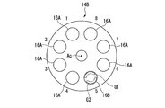
- FIG. 8 is a view corresponding to FIG. 6 in the second embodiment of the present invention.
- a fuel injector 14B according to the second embodiment includes a first main burner 16A as a plurality of main burners 16 and a second main burner 16A, similar to the fuel injector 14A of the first embodiment described above. And a burner 16B.
- the first main burner 16A and the second main burner 16B have the same configuration except that the fuel concentration distribution is different.
- first main burners 16A are continuously arranged in the circumferential direction, and only one second main burner 16B is arranged.
- the fuel injector 14B shown in FIG. 8 shows a case where eight main burners 16 are provided as in FIG. 6, but the number of the main burners 16 is nine or more, and seven or less if it is plural. It may be.
- the fuel injector 14B has a non-periodic arrangement pattern over the entire circumference in the circumferential direction.
- the first main burner 16A and the second main burner 16B are disposed.
- the first main burner 16A and the second main burner 16B are arranged in a circumferentially asymmetrical arrangement pattern (arrangement pattern that is not rotationally symmetrical) about the combustor axis Ac. .
- FIG. 8 illustrates the case where the first group G1 is disposed radially outside of the combustor axis Ac and the second group G2 is disposed inside
- the invention is not limited to this arrangement.
- the arrangement of the first group G1 and the second group G2 in FIG. 8 may be interchanged.
- the first group G1 and the second group G2 may be directed in any direction such as a radial direction and a circumferential direction with the combustor axis Ac as a center.
- the fuel concentration distribution by the first main burner 16A and the fuel concentration distribution by the second main burner 16B may be slightly different, as in the first embodiment. it can. Therefore, it can be suppressed that the flame becomes uniform in the circumferential direction of the fuel injector 14A in which the main burner 16 is disposed.
- the amount of fuel discharged by the first main burner 16A and the second main burner 16B becomes uniform, it is possible to suppress excessive variation in fuel concentration distribution in the entire combustor 3. As a result, the increase in nitrogen oxides (NOx) and the occurrence of combustion oscillation can be suppressed.
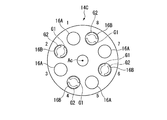
- FIG. 9 is a view corresponding to FIG. 6 in the third embodiment of the present invention.
- a fuel injector 14C according to the third embodiment includes a first main burner 16A as a plurality of main burners 16 and a second main burner 16A, similarly to the fuel injector 14A according to the first embodiment described above. And a burner 16B.
- the first main burner 16A and the second main burner 16B have the same configuration except that the fuel concentration distribution is different.
- the fuel injector 14C in the third embodiment includes four first main burners 16A and four second main burners 16B.
- the fuel injector 14C in the third embodiment shows a case where eight main burners 16 are provided as in the first embodiment, but the number of the main burners 16 is nine or more if it is plural, It may be seven or less.
- the first main burners 16A and the second main burners 16B are alternately arranged in the circumferential direction around the combustor axis Ac.
- the arrangement of the first group G1 and the second group G2 of the second main burner 16B in the third embodiment is not limited to the arrangement shown in FIG. 9 as in the first and second embodiments. .
- the fuel concentration distribution by the first main burner 16A and the fuel concentration distribution by the second main burner 16B may be slightly different, as in the first embodiment. it can. Therefore, the fuel concentration distribution can be prevented from becoming uniform in the circumferential direction of the fuel injector 14A in which the main burner 16 is disposed.
- the amount of fuel discharged by the first main burner 16A and the second main burner 16B becomes uniform, it is possible to suppress excessive variation in fuel concentration distribution in the entire combustor 3. As a result, the increase in nitrogen oxides (NOx) and the occurrence of combustion oscillation can be suppressed.
- the fourth embodiment is different from the first embodiment only in the configuration in which the fuel injection amount of the first group G1 and the fuel injection amount of the second group G2 in the main burner 16B are different. Therefore, while attaching and explaining the same code
- FIG. 10 is a front view corresponding to FIG. 6 in the fourth embodiment of the present invention.
- the main nozzle 23 includes a first fuel supply system F1 and a second fuel supply system F2 which are independent of each other.
- the main burner 16B includes a fuel discharge hole 32 in communication with the first fuel supply system F1 and belonging to the first group G1, and a fuel discharge hole 32 in communication with the second fuel supply system F2 and belonging to the second group G2. .
- the first fuel supply system F1 and the second fuel supply system F2 have different fuel F supply pressures.
- the discharge amount of the fuel F discharged from the discharge hole 32 may be adjustable.
- the first fuel supply system F1 and the second fuel supply may be 0.9: 1.1.
- the fuel discharge hole 32 of the first group G1 and the fuel discharge hole 32 of the second group G2 can be made different. Therefore, in the second main burner 16B, the fuel concentration around the main nozzle 23 can be easily made uneven.
- the arrangement patterns of the first main burner 16A and the second main burner 16B are different from each other, but may be arrangement patterns other than those described above. It is sufficient that both the first main burner 16A and the second main burner 16B be provided, and for example, the arrangement pattern from case 1 to case 22 shown in the following table may be adopted.
- the numbers “1” to “22” described in the leftmost column are cases, and the numbers “1” to “8” described at the top in each column are the embodiments described above.
- the positions “1” to “8” of the main burner 16 in the circumferential direction of The rightmost column is the "number" of the second main burners 16B in one fuel injector.
- case “1” is an arrangement pattern obtained by rotating the arrangement pattern of the second embodiment around the nozzle center axis P3, and substantially the same results were obtained.
- the case “6” is also an arrangement pattern obtained by rotating the arrangement pattern of the first embodiment around the nozzle center axis P3, and substantially the same results were obtained.
- Case “22” is the same arrangement pattern as the third embodiment.
- three patterns of case “1”, case “6” and case “22” will be described as representative examples.
- the present invention is not limited to the configurations of the above-described embodiments, and design changes can be made without departing from the scope of the invention.
- the case where the fuel concentration in the circumferential direction in the first main burner 16A is substantially uniform has been described.
- the variation in the fuel concentration in the circumferential direction in the first main burner 16A may be smaller than that in the second main burner 16B, and is not limited to the case where the fuel concentration is uniform.
- the group having different fuel injection amounts are not limited to two. Three or more groups may be formed.
- the kind of injection quantity is good also as three or more types.
- the configuration has been described in which the second main burner 16B generates the premixed air-fuel mixture having an uneven fuel concentration in the circumferential direction around the nozzle center axis P3.
- the second main burner 16B is configured to be able to suppress the flame dispersion of the entire combustor 3 while making the flame different from the flame of the premixed air generated by the first main burner 16A, the nozzle central axis
- the present invention is not limited to the configuration that makes the fuel concentration uneven in the circumferential direction around P3.
- the fuel discharge holes 28 and 32 are formed in the main swirler 25 , but the fuel discharge holes 28 and 32 are not limited to those formed in the main swirler 25.
- the fuel discharge holes 28 and 32 may be formed on the outer peripheral surface of the main nozzle 23.
- the ratio of the hole diameter of the fuel discharge hole 32 of the first group G1 to the hole diameter of the fuel discharge hole 32 of the second group G2, the fuel discharge hole 32 of the first group G1 and the fuel discharge hole 32 of the second group G2 is not limited to the ratio of each embodiment described above.
- the present invention is applicable to a combustor. According to this combustor, the increase of nitrogen oxides and the occurrence of combustion oscillation can be suppressed.
Landscapes
- Engineering & Computer Science (AREA)
- Chemical & Material Sciences (AREA)
- Combustion & Propulsion (AREA)
- Mechanical Engineering (AREA)
- General Engineering & Computer Science (AREA)
Abstract
燃焼器は、周方向に間隔をあけて複数配置されたメインバーナーを備える。前記メインバーナーは、それぞれ混合気を生成する第一メインバーナー(16A)と第二メインバーナー(16B)とを含む。第二メインバーナー(16B)は、前記第一メインバーナー(16A)よりも燃料濃度が不均一な混合気を生成する。
Description
この発明は、燃焼器及びガスタービンに関する。
本願は、2017年7月19日に、日本に出願された特願2017-140209号に基づき優先権を主張し、その内容をここに援用する。
本願は、2017年7月19日に、日本に出願された特願2017-140209号に基づき優先権を主張し、その内容をここに援用する。
ガスタービンの燃焼器としては、パイロットバーナーの周りに、複数のメインバーナーを等間隔に並べて備えたものが知られている。このような燃焼器においては、メインバーナーに圧力変動が生じた場合に、火炎が周方向で同じ変動を起こす、いわゆる燃焼振動が生じる可能性が有った。
特許文献1には、燃焼振動を抑制するために、複数のメイン予混合ノズルのうち、一部のメイン予混合ノズルから供給する燃料量を少なくする技術が提案されている。この特許文献1の技術によれば、少ない燃料量を供給した希薄予混合気の火炎を、燃料濃度を薄くしていない予混合気の火炎と比較して、長火炎とすることが可能となっている。
特許文献2には、燃焼振動を抑制するために、一部のメインノズルの楕円延長管の出口形状を、他のメインノズルの出口形状と異ならせて、着火位置をずらす技術が提案されている。この特許文献2の技術によれば、内筒内の狭い領域に発熱が集中することを防止して燃焼振動を抑制できる。
特許文献1には、燃焼振動を抑制するために、複数のメイン予混合ノズルのうち、一部のメイン予混合ノズルから供給する燃料量を少なくする技術が提案されている。この特許文献1の技術によれば、少ない燃料量を供給した希薄予混合気の火炎を、燃料濃度を薄くしていない予混合気の火炎と比較して、長火炎とすることが可能となっている。
特許文献2には、燃焼振動を抑制するために、一部のメインノズルの楕円延長管の出口形状を、他のメインノズルの出口形状と異ならせて、着火位置をずらす技術が提案されている。この特許文献2の技術によれば、内筒内の狭い領域に発熱が集中することを防止して燃焼振動を抑制できる。
その一方で、ガスタービンの燃焼器においては、窒素酸化物(NOx)等を低減することが望まれている。
特許文献3には、窒素酸化物の発生を抑制するために、冷却空気が混入したとしても軸方向において火炎面が均一になるように予混合気の燃料濃度をノズルの中心軸周りに変化させる技術が記載されている。
特許文献3には、窒素酸化物の発生を抑制するために、冷却空気が混入したとしても軸方向において火炎面が均一になるように予混合気の燃料濃度をノズルの中心軸周りに変化させる技術が記載されている。
しかしながら、特許文献1に記載された燃焼器は、一部のメイン予混合ノズルから供給する燃料量を少なくしているため、燃焼器全体の燃料濃度分布のバラつきが大きくなり過ぎて、窒素酸化物(NOx)が増加してしまう可能性が有る。
特許文献2に記載のメインバーナーは、全てのメインノズルからの予混合気が同一位置で着火、燃焼することを防止できるものの、やはり、燃焼器全体の燃料濃度分布のバラつきが大きくなり過ぎて、窒素酸化物(NOx)が増加してしまう可能性が有る。
その一方で、特許文献1,2において、窒素酸化物(NOx)を抑制しようとして燃料濃度分布のバラつきを小さくしようとすると、燃焼振動が増大する可能性が有る。
また、特許文献3のようにして窒素酸化物(NOx)を低減しようとすると、燃焼振動が増大してしまう可能性が有る。
特許文献2に記載のメインバーナーは、全てのメインノズルからの予混合気が同一位置で着火、燃焼することを防止できるものの、やはり、燃焼器全体の燃料濃度分布のバラつきが大きくなり過ぎて、窒素酸化物(NOx)が増加してしまう可能性が有る。
その一方で、特許文献1,2において、窒素酸化物(NOx)を抑制しようとして燃料濃度分布のバラつきを小さくしようとすると、燃焼振動が増大する可能性が有る。
また、特許文献3のようにして窒素酸化物(NOx)を低減しようとすると、燃焼振動が増大してしまう可能性が有る。
この発明は、上記事情に鑑みてなされたものであり、窒素酸化物の増加、及び燃焼振動の発生をそれぞれ抑制することができる燃焼器及びガスタービンを提供するものである。
上記の課題を解決するために以下の構成を採用する。
この発明の第一態様によれば、燃焼器は、周方向に間隔をあけて複数配置されたメインバーナーを備える。前記メインバーナーは、それぞれ混合気を生成する第一メインバーナーと第二メインバーナーとを含む。第二メインバーナーは、前記第一メインバーナーよりも燃料濃度が不均一な混合気を生成する。第一メインバーナーと、第二メインバーナーとは、周方向の全周に渡って非周期的な配置パターンで配置されている。
このように構成することで、第一メインバーナーによる火炎と、第二メインバーナーによる火炎とを僅かに異なるものとすることができる。そのため、メインバーナーの配置される周方向で、燃料濃度分布が一様になることを抑制できる。その一方で、燃焼器全体で燃料濃度分布が過度にバラつくことを抑制できる。第一メインバーナーと第二メインバーナーとを回転対称に配置しないため、周方向で一様な火炎となることを抑制できる。
したがって、窒素酸化物の増加、及び燃焼振動の発生をそれぞれ抑制することができる。
この発明の第一態様によれば、燃焼器は、周方向に間隔をあけて複数配置されたメインバーナーを備える。前記メインバーナーは、それぞれ混合気を生成する第一メインバーナーと第二メインバーナーとを含む。第二メインバーナーは、前記第一メインバーナーよりも燃料濃度が不均一な混合気を生成する。第一メインバーナーと、第二メインバーナーとは、周方向の全周に渡って非周期的な配置パターンで配置されている。
このように構成することで、第一メインバーナーによる火炎と、第二メインバーナーによる火炎とを僅かに異なるものとすることができる。そのため、メインバーナーの配置される周方向で、燃料濃度分布が一様になることを抑制できる。その一方で、燃焼器全体で燃料濃度分布が過度にバラつくことを抑制できる。第一メインバーナーと第二メインバーナーとを回転対称に配置しないため、周方向で一様な火炎となることを抑制できる。
したがって、窒素酸化物の増加、及び燃焼振動の発生をそれぞれ抑制することができる。
この発明の第二態様によれば、第一態様に係る第二メインバーナーは、前記混合気の燃料濃度を、メインノズルを中心とした周方向で、前記第一メインバーナーよりも不均一とするようにしてもよい。
このようにすることで、メインノズルの周方向で、第二メインバーナーによる火炎の形状を第一メインバーナーによる火炎に対して僅かに変化させることができる。
このようにすることで、メインノズルの周方向で、第二メインバーナーによる火炎の形状を第一メインバーナーによる火炎に対して僅かに変化させることができる。
この発明の第三態様によれば、第二態様に係る第二メインバーナーは、前記メインノズルを中心とした周方向の第一側に配置されて燃料を吐出する第一燃料吐出孔と、前記第一側とは反対側となる前記メインノズルを中心とした周方向の第二側に配置されて前記燃料を吐出する第二燃料吐出孔と、を備え、第二燃料吐出孔は、前記第一燃料吐出孔よりも大きい孔径を有するようにしてもよい。
このように構成することで、第一燃料吐出孔よりも第二燃料吐出孔から噴射される燃料量を増加させることができる。したがって、第二メインバーナーにおいて容易にメインノズル周りの燃料濃度を不均一にすることができる。
このように構成することで、第一燃料吐出孔よりも第二燃料吐出孔から噴射される燃料量を増加させることができる。したがって、第二メインバーナーにおいて容易にメインノズル周りの燃料濃度を不均一にすることができる。
この発明の第四態様によれば、第二態様に係る第二メインバーナーは、前記メインノズルを中心とした周方向の第一側に配置されて燃料を吐出する第一燃料吐出孔と、前記第一側とは反対側となる前記メインノズルを中心とした周方向の第二側に配置されて前記燃料を吐出する第二燃料吐出孔と、を備えていてもよい。燃焼器は、前記第一燃料吐出孔に前記燃料を供給する第一燃料供給系統と、前記第一燃料供給系統とは異なる圧力で前記第二燃料吐出孔に前記燃料を供給する第二燃料供給系統と、を更に備えていてもよい。
このように構成することで、第一燃料吐出孔と第二燃料吐出孔との孔径を変えることなく、第一燃料吐出孔と第二燃料吐出孔とから噴射される燃料量を異ならせることができる。したがって、第二メインバーナーにおいて、容易にメインノズル周りの燃料濃度を不均一にすることができる。
このように構成することで、第一燃料吐出孔と第二燃料吐出孔との孔径を変えることなく、第一燃料吐出孔と第二燃料吐出孔とから噴射される燃料量を異ならせることができる。したがって、第二メインバーナーにおいて、容易にメインノズル周りの燃料濃度を不均一にすることができる。
この発明の第五態様によれば、ガスタービンは、第一から第四態様の何れか一つの態様に係る燃焼器を備えている。
このように構成することで、燃焼振動により運転状態が不安定になることを低減できるとともに、窒素酸化物の発生を抑制することができる。したがって、商品性を向上することができる。
このように構成することで、燃焼振動により運転状態が不安定になることを低減できるとともに、窒素酸化物の発生を抑制することができる。したがって、商品性を向上することができる。
上記燃焼器及びガスタービンによれば、窒素酸化物の増加、及び燃焼振動の発生をそれぞれ抑制することができる。
(第一実施形態)
次に、この発明の第一実施形態における燃焼器及びガスタービンを図面に基づき説明する。
図1は、この発明の第一実施形態におけるガスタービンの概略構成を示す図である。 図1に示すように、ガスタービン1は、圧縮機2と、燃焼器3と、タービン4と、を備えている。
圧縮機2は、空気Aを圧縮して圧縮空気を生成する。燃焼器3は、燃料Fを圧縮機2で生成した圧縮空気中で燃焼させて高温高圧の燃焼ガスを生成する。タービン4は、燃焼器3により生成された燃焼ガスにより駆動され、燃焼ガスのエネルギーを回転エネルギーに変換する。
次に、この発明の第一実施形態における燃焼器及びガスタービンを図面に基づき説明する。
図1は、この発明の第一実施形態におけるガスタービンの概略構成を示す図である。 図1に示すように、ガスタービン1は、圧縮機2と、燃焼器3と、タービン4と、を備えている。
圧縮機2は、空気Aを圧縮して圧縮空気を生成する。燃焼器3は、燃料Fを圧縮機2で生成した圧縮空気中で燃焼させて高温高圧の燃焼ガスを生成する。タービン4は、燃焼器3により生成された燃焼ガスにより駆動され、燃焼ガスのエネルギーを回転エネルギーに変換する。
圧縮機2は、圧縮機ロータ6と、圧縮機ケーシング7と、を備えている。また、タービン4は、タービンロータ8と、タービンケーシング9と、を備えている。
圧縮機ロータ6とタービンロータ8は、直列に配置されて回転軸線Arを中心に回転する。タービンロータ8と圧縮機ロータ6とは一体に連結されており、これら圧縮機ロータ6とタービンロータ8とによってガスタービンロータ10が構成されている。このガスタービンロータ10には、例えば、発電機GENのロータが連結されている。
圧縮機ロータ6とタービンロータ8は、直列に配置されて回転軸線Arを中心に回転する。タービンロータ8と圧縮機ロータ6とは一体に連結されており、これら圧縮機ロータ6とタービンロータ8とによってガスタービンロータ10が構成されている。このガスタービンロータ10には、例えば、発電機GENのロータが連結されている。
圧縮機ケーシング7は、圧縮機ロータ6を覆うとともに回転可能に支持している。同様に、タービンケーシング9は、タービンロータ8を覆うとともに回転可能に支持している。圧縮機ケーシング7とタービンケーシング9とは連結されており、これら圧縮機ケーシング7とタービンケーシング9とによってガスタービンケーシング11が構成されている。このガスタービンケーシング11には、燃焼器3が固定されている。
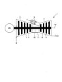
図2は、この発明の第一実施形態における燃焼器の概略構成を示す図である。図3は、この発明の第一実施形態におけるメインバーナーの配置を示す図である。
図2に示すように、燃焼器3は、燃焼筒(又は尾筒)13と、燃料噴射器14Aとを備えている。燃焼筒13は、その内部で燃料Fを燃焼させて、この燃料Fの燃焼により生成される燃焼ガスをタービン4に送る。燃料噴射器14Aは、燃焼筒13内に燃料F及び圧縮空気Aを噴出する。
図2に示すように、燃焼器3は、燃焼筒(又は尾筒)13と、燃料噴射器14Aとを備えている。燃焼筒13は、その内部で燃料Fを燃焼させて、この燃料Fの燃焼により生成される燃焼ガスをタービン4に送る。燃料噴射器14Aは、燃焼筒13内に燃料F及び圧縮空気Aを噴出する。
図3に示すように、燃料噴射器14Aは、パイロットバーナー15と、メインバーナー16と、バーナー保持筒17と、を備えている。
パイロットバーナー15は、燃焼器軸線Ac上に配置され、燃料を拡散燃焼させる。このパイロットバーナー15は、パイロットノズル18と、パイロットバーナー筒19と、パイロットスワラ(図示せず)と、を備えている。
パイロットバーナー15は、燃焼器軸線Ac上に配置され、燃料を拡散燃焼させる。このパイロットバーナー15は、パイロットノズル18と、パイロットバーナー筒19と、パイロットスワラ(図示せず)と、を備えている。
パイロットノズル18は、燃焼器軸線Acを中心とした軸線方向Daに延びるように形成されている。このパイロットノズル18は、例えば、その下流側端部に燃料噴射用の噴射孔18aを有している。
パイロットバーナー筒19は本体部21と、コーン部22と、を備えている。本体部21は、パイロットノズル18の外周を覆っている。コーン部22は、本体部21の下流側に配置されて、下流側向かって次第に拡径するように形成されている。
パイロットスワラ(図示せず)は、パイロットノズル18の噴射孔が形成されている位置よりも軸線方向Daで上流側に配置されている。このパイロットスワラ(図示せず)は、上流側から流れてきた圧縮空気(一次空気)Aを、燃焼器軸線Acを旋回中心にして旋回させる。パイロットスワラ(図示せず)は、例えば、パイロットバーナー筒19の本体部21の内周面から径方向内側に延びている。これらパイロットスワラ(図示せず)は、例えば、周方向に間隔をあけて複数形成されている。
上述した構成を備えるパイロットバーナー15は、そのパイロットバーナー筒19内に、圧縮機2で圧縮された圧縮空気Aが上流側から流入する。また、パイロットノズル18の噴射孔から燃料が噴射される。この燃料は、パイロットスワラ(図示せず)により旋回成分を付与された圧縮空気Aと共に、パイロットバーナー筒19から燃焼筒13に向けて噴出され、燃焼筒13内で拡散燃焼する。
メインバーナー16は、複数設けられ、パイロットバーナー15の外周を囲むように配置され、燃料を予混合燃焼させる。これらメインバーナー16は、燃焼器軸線Acを中心とした周方向に間隔をあけて、より具体的には等間隔に配置されている。この実施形態におけるメインバーナー16としては、第一メインバーナー16Aと、第二メインバーナー16Bとがある。なお、以下の説明において、第一メインバーナー16Aと第二メインバーナー16Bとを区別する必要のない場合には、単にメインバーナー16と称する場合がある。また、第一メインバーナー16Aと第二メインバーナー16Bとにおいて、共通する部分については同一符号を付して重複する説明を省略する。
第一メインバーナー16A、及び第二メインバーナー16Bは、メインノズル23と、メインバーナー筒24と、メインスワラ25と、をそれぞれ備えている。
メインノズル23は、燃焼器軸線Acと平行に延びている。これらメインノズル23は、内部に燃料が流れる燃料流路(図示せず)を備えている。
メインノズル23は、燃焼器軸線Acと平行に延びている。これらメインノズル23は、内部に燃料が流れる燃料流路(図示せず)を備えている。
メインバーナー筒24は、メインノズル23の外周を覆っている。図3に例示するメインバーナー筒24は、燃焼器軸線Acを中心とした径方向における内側に配置される部分が、パイロットバーナー筒19の一部を兼ねている。
メインスワラ25は、上流側から流れてきた圧縮空気(一次空気)Aを、メインノズル23を旋回中心にして旋回させる。メインスワラ25は、それぞれメインノズル23の外周面からメインバーナー筒24の内周面に向かって延びている。メインスワラ25は、複数設けられたメインバーナー16において、それぞれメインノズル23を中心とした周方向に間隔をあけて複数設けられている。
バーナー保持筒17は、上述したパイロットバーナー15及びメインバーナー16を保持している。より具体的には、複数のメインバーナー16がパイロットバーナー15の外周を囲むように、パイロットバーナー15及びメインバーナー16を保持している。
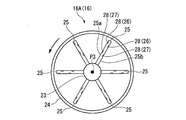
図4は、この発明の第一実施形態における第一メインバーナーの概略構成を示す正面図である。図5は、この発明の第一実施形態における第二メインバーナーの概略構成を示す正面図である。
図4に示すように、第一メインバーナー16Aのメインスワラ25は、それぞれ燃料吐出部26,27を備えている。
図4に示すように、第一メインバーナー16Aのメインスワラ25は、それぞれ燃料吐出部26,27を備えている。
燃料吐出部26,27は、メインスワラ25の圧力面25a及び負圧面25bに形成された一対の燃料吐出孔28によってそれぞれ構成されている。燃料吐出部26は、メインスワラ25の径方向外方側の端部に近い位置に形成され、燃料吐出部27は、燃料吐出部26よりも径方向内方側に形成されている。
燃料吐出孔28は、それぞれメインノズル23の燃料流路に連通している。これら燃料吐出孔28は、燃料吐出部26,27のそれぞれにおいて、圧力面25aに形成された燃料吐出孔28が、負圧面25bに形成された燃料吐出孔28よりも径方向外方側にオフセットしている。
第一メインバーナー16Aに形成された燃料吐出孔28は、メインノズル23のノズル中心軸P3周りで、圧縮空気Aに混合される燃料Fの濃度が実質的に均一となるように形成されている。この実施形態においては、第一メインバーナー16Aに設けられた燃料吐出部26の全ての燃料吐出孔28が同一孔径とされている。同様に、第一メインバーナー16Aに設けられた燃料吐出部27の全ての燃料吐出孔28が同一孔径とされている。なお、上記周方向で燃料濃度が実質的に均一となる孔径であれば、上記のように燃料吐出孔28の孔径を同一にする場合に限られない。
図5に示すように、第二メインバーナー16Bのメインスワラ25は、それぞれ燃料吐出部30,31を備えている。
燃料吐出部30,31は、メインスワラ25の圧力面25a及び負圧面25bに形成された一対の燃料吐出孔32によってそれぞれ構成されている。燃料吐出部30は、メインスワラ25の径方向外方側の端部に近い位置に形成され、燃料吐出部31は、燃料吐出部30よりも径方向内方側に形成されている。
燃料吐出孔32は、それぞれメインノズル23の燃料流路に連通している。これら燃料吐出孔32は、燃料吐出部30,31のそれぞれにおいて、圧力面25aに形成された燃料吐出孔32が、負圧面25bに形成された燃料吐出孔32よりも径方向外方側にオフセットしている。
第二メインバーナー16Bは、第一メインバーナー16Aよりも、ノズル中心軸P3周りおける燃料濃度を変化させて予混合気を燃焼筒13に供給する。この実施形態における第二メインバーナー16Bは、ノズル中心軸P3周りに燃料濃度を変化させて予混合気を燃焼筒に供給する。言い換えれば、第二メインバーナー16Bは、第一メインバーナー16Aよりも燃料濃度が不均一な予混合気を生成する。
第二メインバーナー16Bに形成された複数の燃料吐出孔32は、第一グループG1と第二グループG2とに分けられている。第一グループG1の燃料吐出孔32は、それぞれの吐出した燃料が、燃焼器軸線Acを中心とした径方向で内側の第一の範囲S1(図3参照)に到達する。第二グループG2の燃料吐出孔32は、それぞれの吐出した燃料が燃焼器軸線Acを中心とした径方向で外側の第二の範囲S2(図3参照)に到達する。
この第一実施形態における第二メインバーナー16Bは、燃焼器軸線Ac(図3参照)を中心とした径方向内方側(周方向の第二側)に位置する二つのメインスワラ25の燃料吐出部30及びこれら二つのメインスワラ25に対して旋回方向に隣接する一つのメインスワラ25の燃料吐出部30とにより第一グループG1を構成している。さらに、第二メインバーナー16Bは、燃焼器軸線Ac(図3参照)を中心とした径方向外方側(周方向の第一側)に位置する二つのメインスワラ25を含む残りの三つのメインスワラ25の燃料吐出部30により、第二グループG2を形成している。これら第一グループG1に属する燃料吐出部30と第二グループG2に属する燃料吐出部30とは、それぞれの燃料吐出孔32の開口面積(孔径)が異なっている。なお、六つのメインスワラ25の各燃料吐出部31が備える燃料吐出孔32の大きさは全て同一である。
この第一実施形態の燃料吐出孔32の開口面積(孔径)は、例えば、燃料吐出部31における燃料吐出孔32を「1」とすると、第一グループG1に属した燃料吐出部30の燃料吐出孔32が「0.9」に設定され、第二グループG2に属する燃料吐出部30の燃料吐出孔32が「1.1」に設定されている。このような構成により、メインノズル23の燃料流路における燃料Fに圧力を作用させると、各燃料吐出孔32から開口面積に応じた量の燃料Fが圧縮空気Aに吐出される。
つまり、一つのメインスワラ25に形成された複数の燃料吐出孔32のうち、メインノズル23のノズル中心軸P3を中心とした径方向外方側に配置された燃料吐出孔32の燃料吐出量と、径方向内方側に配置された燃料吐出孔32の燃料吐出量とは、それぞれ異なっている。さらに、六つのメインスワラ25の各燃料吐出部30の燃料吐出量は、メインノズル23のノズル中心軸P3周りで二種類に分かれている。
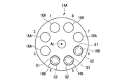
図6は、この発明の第一実施形態における第一メインバーナーと第二メインバーナーとの配置を示す正面図である。
図6に示すように、燃料噴射器14Aは、燃焼器軸線Acを中心とした周方向で連続して並ぶ五つの第一メインバーナー16Aと、同じく周方向で連続して並ぶ三つの第二メインバーナー16Bとを備えている。
図6に示すように、燃料噴射器14Aは、燃焼器軸線Acを中心とした周方向で連続して並ぶ五つの第一メインバーナー16Aと、同じく周方向で連続して並ぶ三つの第二メインバーナー16Bとを備えている。
ここで、図6に示す燃料噴射器14Aは、8つのメインバーナー16を備える場合を示しているが、メインバーナー16の数は、複数であれば9つ以上や、7つ以下であっても良い。また、第一メインバーナー16Aの個数と第二メインバーナー16Bの個数とは、上記の個数に限られない。燃料噴射器14Aは、第一メインバーナー16Aと第二メインバーナー16Bとを両方備えていればよい。なお、図6において、周方向に並んだ8つのメインバーナー16の位置をそれぞれ配置番号「1」から「8」で示している。
この第一実施形態における燃料噴射器14Aは、第一メインバーナー16Aと第二メインバーナー16Bとが、周方向の全周に渡って非周期的な配置パターンで配置されている。ここで、「周期的な配置パターン」とは、燃焼器軸線Acを中心として周方向に一周する間に、第一メインバーナー16Aと第二メインバーナー16Bとの配置されている順序のパターンが同一のパターンのみで繰り返されることである。周期的な場合の一例としては、第一メインバーナー16Aと第二メインバーナー16Bとが周方向に交互に配置されている場合や、第一メインバーナー16Aのみが配置される場合や、第二メインバーナー16Bのみが配置される場合などを挙げることができる。
つまり、この第一実施形態における燃料噴射器14Aにおけるメインバーナー16の配置パターンは、燃焼器軸線Acを中心として周方向に一周する間に、第一メインバーナー16Aと第二メインバーナー16Bとの配置されている順序のパターンが同一のパターンのみで繰り返されていない。
また、この第一実施形態における燃料噴射器14Aは、第一メインバーナー16Aと第二メインバーナー16Bとが、燃焼器軸線Acを中心とした周方向で非対称な配置パターンで配置されている。この「周方向で非対称な配置パターン」とは、いわゆる回転対称となるような順序で第一メインバーナー16Aと第二メインバーナー16Bが配置されていないことを意味している。
燃料噴射器14Aの第二メインバーナー16Bは、第一グループG1と第二グループG2とが、燃焼器軸線Acを中心とした径方向で内側と外側とに分かれるように配置されている。つまり、燃料噴射器14Aは、第二メインバーナー16Bが配置される箇所において、予混合気の燃料濃度が、燃焼器軸線Acを中心とした径方向で不均一となっている。言い換えれば、第二メインバーナー16Bは、メインノズル23を中心とした周方向で、予混合気の燃料濃度が不均一になっている。この第一実施形態においては、第一グループG1が径方向の内側に配置され、第二グループG2が径方向の外側に配置される場合を例示している。
したがって、上述した第一実施形態によれば、第一メインバーナー16Aによる火炎と、第二メインバーナー16Bによる火炎とを僅かに異なるものとすることができる。そのため、メインバーナー16の配置される燃料噴射器14Aの周方向で、燃料濃度分布が一様になることを抑制できる。その一方で、第一メインバーナー16Aと第二メインバーナー16Bとにより吐出される燃料量のバラつきは抑制できるので、燃焼器3全体で燃料濃度分布が過度にバラつくことを抑制できる。その結果、窒素酸化物(NOx)の増加、及び燃焼振動の発生をそれぞれ抑制することができる。
さらに、第一メインバーナー16Aと第二メインバーナー16Bとを回転対称に配置しないため、周方向で一様な燃料濃度分布となることを抑制できる。
また、ノズル中心軸P3を中心とした周方向で、第二メインバーナー16Bによる火炎の形状を第一メインバーナー16Aによる火炎に対して僅かに変化させることができる。
また、ノズル中心軸P3を中心とした周方向で、第二メインバーナー16Bによる火炎の形状を第一メインバーナー16Aによる火炎に対して僅かに変化させることができる。
さらに、第一グループG1の燃料吐出孔32(第一燃料吐出孔)の孔径(開口面積)よりも第二グループG2の燃料吐出孔32(第二燃料吐出孔)の孔径(開口面積)を大きくしている。そのため、第一グループG1の燃料吐出孔32から吐出される燃料量よりも第二グループG2の燃料吐出孔32から吐出される燃料量を増加させることができる。その結果、第二メインバーナー16Bにおいて容易にメインノズル23周り(言い換えれば、ノズル中心軸P3周り)の燃料濃度を不均一にすることができる。
また、燃焼振動により運転状態が不安定になることを低減できるとともに、窒素酸化物の発生を抑制することができるため、燃焼器3の商品性を向上することができる。
(第一実施形態の変形例)
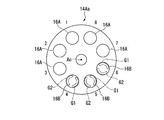
図7は、この発明の第一実施形態の変形例における図6に相当する正面図である。
上述した第一実施形態の燃料噴射器14Aにおいては、第一グループG1と第二グループG2とが燃焼器軸線Acを中心とした径方向にそれぞれ分かれて配置される場合について説明した。しかし、第二メインバーナー16Bにおける第一グループG1と第二グループG2との配置は、第一実施形態で例示した配置に限られない。
例えば、図7に示す燃料噴射器14Aaように、第二メインバーナー16Bは、第一グループG1と第二グループG2とが、燃焼器軸線Acを中心とした周方向でそれぞれ分かれて配置されていても良い。
図7は、この発明の第一実施形態の変形例における図6に相当する正面図である。
上述した第一実施形態の燃料噴射器14Aにおいては、第一グループG1と第二グループG2とが燃焼器軸線Acを中心とした径方向にそれぞれ分かれて配置される場合について説明した。しかし、第二メインバーナー16Bにおける第一グループG1と第二グループG2との配置は、第一実施形態で例示した配置に限られない。
例えば、図7に示す燃料噴射器14Aaように、第二メインバーナー16Bは、第一グループG1と第二グループG2とが、燃焼器軸線Acを中心とした周方向でそれぞれ分かれて配置されていても良い。
また、上述した第一実施形態では、第一グループG1が燃焼器軸線Acを中心とした径方向の内側に配置され、第二グループG2が燃焼器軸線Acを中心とした径方向の外側に配置される場合を例示した。しかし、他の変形例として、第一グループG1が燃焼器軸線Acを中心とした径方向の外側に配置され、第二グループG2が燃焼器軸線Acを中心とした径方向の内側に配置されていてもよい。
さらに、全ての第一グループG1が、燃焼器軸線Acを中心とした径方向の内側と外側との何れか一方に配置される場合について説明したが、一つの燃料噴射器14Aにおいて、第一グループG1が燃焼器軸線Acを中心とした径方向の内側に配置された第二メインバーナー16Bと、第一グループG1が燃焼器軸線Acを中心とした径方向の外側に配置された第二メインバーナー16Bとをそれぞれ両方設けるようにしても良い。
また、上述した第一実施形態や変形例においては、第一グループG1と第二グループG2とを燃焼器軸線Acを中心とした径方向に分けて配置した第二メインバーナー16Bのみを備える場合、又は、第一グループG1と第二グループG2とを燃焼器軸線Acを中心とした周方向に分けて配置した第二メインバーナー16Bのみを備える場合について説明した。しかし、燃料噴射器14Aには、第一グループG1と第二グループG2との配置が燃焼器軸線Acを中心とした径方向で分けられた第二メインバーナー16Bと、第一グループG1と第二グループG2との配置が燃焼器軸線Acを中心とした周方向で分けられた第二メインバーナー16Bとを混在させるようにしてもよい。
(第二実施形態)
次に、この発明の第二実施形態を図面に基づき説明する。この第二実施形態は、上述した第一実施形態に対してメインバーナーの配置パターンを変化させたものである。そのため、上述した第一実施形態と同一部分に同一符号を付して説明するとともに、重複する説明を省略する。
図8は、この発明の第二実施形態における図6に相当する図である。
図8に示すように、この第二実施形態における燃料噴射器14Bは、上述した第一実施形態の燃料噴射器14Aと同様に、複数のメインバーナー16として第一メインバーナー16Aと、第二メインバーナー16Bと、を備えている。これら第一メインバーナー16Aと第二メインバーナー16Bとは、第一実施形態で説明したように、燃料濃度の分布が異なる点を除いて同一の構成となっている。
次に、この発明の第二実施形態を図面に基づき説明する。この第二実施形態は、上述した第一実施形態に対してメインバーナーの配置パターンを変化させたものである。そのため、上述した第一実施形態と同一部分に同一符号を付して説明するとともに、重複する説明を省略する。
図8は、この発明の第二実施形態における図6に相当する図である。
図8に示すように、この第二実施形態における燃料噴射器14Bは、上述した第一実施形態の燃料噴射器14Aと同様に、複数のメインバーナー16として第一メインバーナー16Aと、第二メインバーナー16Bと、を備えている。これら第一メインバーナー16Aと第二メインバーナー16Bとは、第一実施形態で説明したように、燃料濃度の分布が異なる点を除いて同一の構成となっている。
この第二実施形態における燃料噴射器14Bは、7つの第一メインバーナー16Aが周方向に連続して配置されるとともに、1つだけ第二メインバーナー16Bが配置されている。図8に示す燃料噴射器14Bは、図6と同様に、8つのメインバーナー16を備える場合を示しているが、メインバーナー16の数は、複数であれば9つ以上や、7つ以下であっても良い。
燃料噴射器14Bは、第二メインバーナー16Bが一つだけ設けられていることで、第一実施形態の燃料噴射器14Aと同様に、周方向の全周に渡って非周期的な配置パターンで第一メインバーナー16Aと第二メインバーナー16Bとが配置されている。
さらに、燃料噴射器14Bは、第一メインバーナー16Aと第二メインバーナー16Bとが、燃焼器軸線Acを中心とした周方向で非対称な配置パターン(回転対称ではない配置パターン)で配置されている。
さらに、燃料噴射器14Bは、第一メインバーナー16Aと第二メインバーナー16Bとが、燃焼器軸線Acを中心とした周方向で非対称な配置パターン(回転対称ではない配置パターン)で配置されている。
図8においては、燃焼器軸線Acを中心とした径方向の外側に第一グループG1が配置され、内側に第二グループG2が配置される場合を例示したが、この配置に限られない。例えば、図8の第一グループG1と第二グループG2との配置は入れ替えてもよい。また、第一グループG1と第二グループG2とは、燃焼器軸線Acを中心とし径方向及び周方向等、何れの方向に向くようにしても良い。
したがって、上述した第二実施形態によれば、第一実施形態と同様に、第一メインバーナー16Aによる燃料濃度分布と、第二メインバーナー16Bによる燃料濃度分布とを僅かに異なるものとすることができる。そのため、メインバーナー16の配置される燃料噴射器14Aの周方向で、火炎が一様になることを抑制できる。その一方で、第一メインバーナー16Aと第二メインバーナー16Bとにより吐出される燃料量は均一になるので、燃焼器3全体で燃料濃度分布が過度にバラつくことを抑制できる。その結果、窒素酸化物(NOx)の増加、及び燃焼振動の発生をそれぞれ抑制することができる。
(第三実施形態)
次に、この発明の第三実施形態を図面に基づき説明する。この第三実施形態は、第二実施形態と同様に、上述した第一実施形態に対してメインバーナーの配置パターンを変化させたものである。そのため、上述した第一実施形態と同一部分に同一符号を付して説明するとともに、重複する説明を省略する。
次に、この発明の第三実施形態を図面に基づき説明する。この第三実施形態は、第二実施形態と同様に、上述した第一実施形態に対してメインバーナーの配置パターンを変化させたものである。そのため、上述した第一実施形態と同一部分に同一符号を付して説明するとともに、重複する説明を省略する。
図9は、この発明の第三実施形態における図6に相当する図である。
図9に示すように、この第三実施形態における燃料噴射器14Cは、上述した第一実施形態の燃料噴射器14Aと同様に、複数のメインバーナー16として第一メインバーナー16Aと、第二メインバーナー16Bと、を備えている。これら第一メインバーナー16Aと第二メインバーナー16Bとは、第一実施形態で説明したように、燃料濃度の分布が異なる点を除いて同一の構成となっている。
図9に示すように、この第三実施形態における燃料噴射器14Cは、上述した第一実施形態の燃料噴射器14Aと同様に、複数のメインバーナー16として第一メインバーナー16Aと、第二メインバーナー16Bと、を備えている。これら第一メインバーナー16Aと第二メインバーナー16Bとは、第一実施形態で説明したように、燃料濃度の分布が異なる点を除いて同一の構成となっている。
この第三実施形態における燃料噴射器14Cは、4つの第一メインバーナー16Aを備えるとともに、4つの第二メインバーナー16Bを備えている。この第三実施形態における燃料噴射器14Cは、第一実施形態と同様に、8つのメインバーナー16を備える場合を示しているが、メインバーナー16の数は、複数であれば9つ以上や、7つ以下であっても良い。
この第三実施形態における燃料噴射器14Cは、燃焼器軸線Acを中心とした周方向で第一メインバーナー16Aと第二メインバーナー16Bとが交互に配置されている。
なお、この第三実施形態における第二メインバーナー16Bも、第一、第二実施形態と同様に、第一グループG1と第二グループG2との配置は図9に示す配置に限られるものではない。
なお、この第三実施形態における第二メインバーナー16Bも、第一、第二実施形態と同様に、第一グループG1と第二グループG2との配置は図9に示す配置に限られるものではない。
したがって、上述した第三実施形態によれば、第一実施形態と同様に、第一メインバーナー16Aによる燃料濃度分布と、第二メインバーナー16Bによる燃料濃度分布とを僅かに異なるものとすることができる。そのため、メインバーナー16の配置される燃料噴射器14Aの周方向で、燃料濃度分布が一様になることを抑制できる。その一方で、第一メインバーナー16Aと第二メインバーナー16Bとにより吐出される燃料量は均一になるので、燃焼器3全体で燃料濃度分布が過度にバラつくことを抑制できる。その結果、窒素酸化物(NOx)の増加、及び燃焼振動の発生をそれぞれ抑制することができる。
(第四実施形態)
次に、この発明の第四実施形態を図面に基づき説明する。この第四実施形態は、メインバーナー16Bにおける第一グループG1の燃料噴射量と第二グループG2の燃料噴射量を異ならせる構成のみが上述した第一実施形態と相違する。そのため、上述した第一実施形態と同一部分に同一符号を付して説明するとともに、重複する説明を省略する。
次に、この発明の第四実施形態を図面に基づき説明する。この第四実施形態は、メインバーナー16Bにおける第一グループG1の燃料噴射量と第二グループG2の燃料噴射量を異ならせる構成のみが上述した第一実施形態と相違する。そのため、上述した第一実施形態と同一部分に同一符号を付して説明するとともに、重複する説明を省略する。
図10は、この発明の第四実施形態における図6に相当する正面図である。
図10に示すように、この第四実施形態におけるメインバーナー16Bは、メインノズル23が、互いに独立した第一燃料供給系統F1と、第二燃料供給系統F2と、を備えている。メインバーナー16Bは、第一燃料供給系統F1に連通し第一グループG1に属する燃料吐出孔32と、第二燃料供給系統F2に連通し第二グループG2に属する燃料吐出孔32とを備えている。
図10に示すように、この第四実施形態におけるメインバーナー16Bは、メインノズル23が、互いに独立した第一燃料供給系統F1と、第二燃料供給系統F2と、を備えている。メインバーナー16Bは、第一燃料供給系統F1に連通し第一グループG1に属する燃料吐出孔32と、第二燃料供給系統F2に連通し第二グループG2に属する燃料吐出孔32とを備えている。
第一燃料供給系統F1及び第二燃料供給系統F2は、それぞれ燃料Fの供給圧力が異なる。第一燃料供給系統F1及び第二燃料供給系統F2は、例えば、第一グループG1に属するメインスワラ25の燃料吐出孔32から吐出する燃料Fの吐出量と、第二グループG2に属するメインスワラ25の燃料吐出孔32から吐出する燃料Fの吐出量とを、それぞれ調整可能としてもよい。なお、この第四実施形態においては、第一実施形態における第一グループG1と第二グループG2とにおける各燃料吐出孔32の孔径の比率と同様に、第一燃料供給系統F1と第二燃料供給系統F2とによって供給される燃料Fの圧力比を0.9:1.1としてもよい。
したがって、上述した第四実施形態によれば、第一グループG1の燃料吐出孔32と第二グループG2の燃料吐出孔32との孔径を変えることなく、第一グループG1の燃料吐出孔32と第二グループG2の燃料吐出孔32とから吐出される燃料量を異ならせることができる。したがって、第二メインバーナー16Bにおいて、容易にメインノズル23周りの燃料濃度を不均一にすることができる。
(その他の実施形態)
第一実施形態から第四実施形態においては、それぞれ第一メインバーナー16Aと第二メインバーナー16Bとの配置パターンを異なるものとしたが、上述した以外の配置パターンであっても良い。第一メインバーナー16Aと第二メインバーナー16Bとの両方を備えていればよく、例えば、以下の表に示すケース1からケース22までの配置パターンとしても良い。以下の表において、最も左側の列に記載された数字「1」から「22」がケースであり、各列における最も上に記載した「1」から「8」の数字は、上述した各実施形態の周方向におけるメインバーナー16の位置「1」から「8」に対応している。また、最も右側の列は、一つの燃料噴射器における第二メインバーナー16Bの「本数」である。さらに、上記の表の各ケースにおいて、第一メインバーナー16Aが配置されている場合に「0」、第二メインバーナー16Bが配置されている場合に「1」としている。なお、メインバーナー16の配置パターンについては、以下の表のものに限られず、以下の表の配置パターンを、周方向に回転させた配置パターンであっても良い。
第一実施形態から第四実施形態においては、それぞれ第一メインバーナー16Aと第二メインバーナー16Bとの配置パターンを異なるものとしたが、上述した以外の配置パターンであっても良い。第一メインバーナー16Aと第二メインバーナー16Bとの両方を備えていればよく、例えば、以下の表に示すケース1からケース22までの配置パターンとしても良い。以下の表において、最も左側の列に記載された数字「1」から「22」がケースであり、各列における最も上に記載した「1」から「8」の数字は、上述した各実施形態の周方向におけるメインバーナー16の位置「1」から「8」に対応している。また、最も右側の列は、一つの燃料噴射器における第二メインバーナー16Bの「本数」である。さらに、上記の表の各ケースにおいて、第一メインバーナー16Aが配置されている場合に「0」、第二メインバーナー16Bが配置されている場合に「1」としている。なお、メインバーナー16の配置パターンについては、以下の表のものに限られず、以下の表の配置パターンを、周方向に回転させた配置パターンであっても良い。

次に、上述した各実施形態の燃料噴射器を有する燃焼器の実施例について説明する。 第一メインバーナー16A及び第二メインバーナー16Bが配置される配置パターンについて、シミュレーションにより上記の表に示すケース「1」からケース「22」のそれぞれの燃焼振動の大きさを求めた。
(実施例)
ここで、ケース「1」は、第二実施形態の配置パターンをノズル中心軸P3周りに回転させた配置パターンであり、これらは実質的に同一の結果が得られた。また、ケース「6」も、第一実施形態の配置パターンをノズル中心軸P3周りに回転させた配置パターンでありこれらは実質的に同一の結果が得られた。ケース「22」は、第三実施形態と同じ配置パターンである。ここでは、これらケース「1」、ケース「6」、ケース「22」の三パターンを代表的な実施例として説明する。
ここで、ケース「1」は、第二実施形態の配置パターンをノズル中心軸P3周りに回転させた配置パターンであり、これらは実質的に同一の結果が得られた。また、ケース「6」も、第一実施形態の配置パターンをノズル中心軸P3周りに回転させた配置パターンでありこれらは実質的に同一の結果が得られた。ケース「22」は、第三実施形態と同じ配置パターンである。ここでは、これらケース「1」、ケース「6」、ケース「22」の三パターンを代表的な実施例として説明する。
(比較例)
上記の表にはない、燃料噴射器14A~14Cが備えるメインバーナー16の全てが、第一メインバーナー16Aの場合を比較例1、及び、メインバーナー16の全てが第二メインバーナー16Bの場合を比較例2とした。
上記の表にはない、燃料噴射器14A~14Cが備えるメインバーナー16の全てが、第一メインバーナー16Aの場合を比較例1、及び、メインバーナー16の全てが第二メインバーナー16Bの場合を比較例2とした。
(燃焼振動)
ケース「1」、ケース「6」、ケース「22」、比較例1および比較例2について、圧力と周波数をパラメータに、燃焼振動による圧力変動のシミュレーション計算を行った。
シミュレーション結果を比較した結果、ケース「1」、「6」、「22」において、それぞれ比較例1,2よりも燃焼振動が低減される傾向が確認された。
これらケース「1」、「6」、「22」は、何れも、第一メインバーナー16Aと第二メインバーナー16Bとの両方を備えている。特に、ケース「6」において、燃焼振動の低減が顕著となった。
つまり、第一メインバーナー16Aと第二メインバーナー16Bとの両方を備える配置パターンと、燃焼振動の低減との間に相関があることが確認された。
ケース「1」、ケース「6」、ケース「22」、比較例1および比較例2について、圧力と周波数をパラメータに、燃焼振動による圧力変動のシミュレーション計算を行った。
シミュレーション結果を比較した結果、ケース「1」、「6」、「22」において、それぞれ比較例1,2よりも燃焼振動が低減される傾向が確認された。
これらケース「1」、「6」、「22」は、何れも、第一メインバーナー16Aと第二メインバーナー16Bとの両方を備えている。特に、ケース「6」において、燃焼振動の低減が顕著となった。
つまり、第一メインバーナー16Aと第二メインバーナー16Bとの両方を備える配置パターンと、燃焼振動の低減との間に相関があることが確認された。
この発明は上述した各実施形態の構成に限られるものではなく、その要旨を逸脱しない範囲で設計変更可能である。
各実施形態においては、第一メインバーナー16Aにおける周方向の燃料濃度が実質的に均一となる場合について説明した。しかし、第一メインバーナー16Aにおける周方向の燃料濃度のバラつきは、第二メインバーナー16Bよりも少なければよく、燃料濃度が均一な場合に限られない。
各実施形態においては、第一メインバーナー16Aにおける周方向の燃料濃度が実質的に均一となる場合について説明した。しかし、第一メインバーナー16Aにおける周方向の燃料濃度のバラつきは、第二メインバーナー16Bよりも少なければよく、燃料濃度が均一な場合に限られない。
また、各実施形態においては、第二メインバーナー16Bがそれぞれ燃料噴射量の異なる第一グループG1と第二グループG2とを備える場合について説明した。しかし、燃料噴射量の異なるグループは二つに限られない。三つ以上のグループを形成するようにしても良い。また、第二メインバーナー16Bの備えるグループ数に応じて、噴射量の種類は、三種類以上としてもよい。
さらに、第二メインバーナー16Bがノズル中心軸P3を中心とした周方向で燃料濃度が不均一な予混合気を生成する構成について説明した。しかし、第二メインバーナー16Bは、第一メインバーナー16Aにより生成した予混合気による火炎と、異なる火炎にしつつ、燃焼器3全体の火炎のバラつきを抑えることができる構成であれば、ノズル中心軸P3を中心とした周方向で燃料濃度を不均一にする構成に限られるものでは無い。
また、各実施形態においては、燃料吐出孔28,32がメインスワラ25に形成される場合について説明したが、燃料吐出孔28,32は、メインスワラ25に形成されているものに限られない。例えば、メインノズル23の外周面に、燃料吐出孔28,32を形成するようにしても良い。
さらに、第一グループG1の燃料吐出孔32の孔径と第二グループG2の燃料吐出孔32の孔径との比率や、第一グループG1の燃料吐出孔32と第二グループG2の燃料吐出孔32とから吐出される燃料量の比率は、上述した各実施形態の比率に限られない。
この発明は、燃焼器に適用できる。この燃焼器によれば、窒素酸化物の増加、及び燃焼振動の発生をそれぞれ抑制することができる。
1 ガスタービン
2 圧縮機
3 燃焼器
4 タービン
6 圧縮機ロータ
7 圧縮機ケーシング
8 タービンロータ
9 タービンケーシング
10 ガスタービンロータ
11 ガスタービンケーシング
13 燃焼筒
14A,14Aa,14B,14C,14D 燃料噴射器
15 パイロットバーナー
16 メインバーナー
16A 第一メインバーナー
16B 第二メインバーナー
17 バーナー保持筒
18 パイロットノズル
18a 噴射孔
19 パイロットバーナー筒
21 本体部
22 コーン部
23 メインノズル
24 メインバーナー筒
25 メインスワラ
25a 圧力面
25b 負圧面
26,27,30,31 燃料吐出部
28,32 燃料吐出孔
A 空気,圧縮空気
Ac 燃焼器軸線
Ar 回転軸線
Da 軸線方向
F 燃料
F1 第一燃料供給系統
F2 第二燃料供給系統
G1 第一グループ
G2 第二グループ
GEN 発電機
P3 ノズル中心軸
S1 第一の範囲
S2 第二の範囲
2 圧縮機
3 燃焼器
4 タービン
6 圧縮機ロータ
7 圧縮機ケーシング
8 タービンロータ
9 タービンケーシング
10 ガスタービンロータ
11 ガスタービンケーシング
13 燃焼筒
14A,14Aa,14B,14C,14D 燃料噴射器
15 パイロットバーナー
16 メインバーナー
16A 第一メインバーナー
16B 第二メインバーナー
17 バーナー保持筒
18 パイロットノズル
18a 噴射孔
19 パイロットバーナー筒
21 本体部
22 コーン部
23 メインノズル
24 メインバーナー筒
25 メインスワラ
25a 圧力面
25b 負圧面
26,27,30,31 燃料吐出部
28,32 燃料吐出孔
A 空気,圧縮空気
Ac 燃焼器軸線
Ar 回転軸線
Da 軸線方向
F 燃料
F1 第一燃料供給系統
F2 第二燃料供給系統
G1 第一グループ
G2 第二グループ
GEN 発電機
P3 ノズル中心軸
S1 第一の範囲
S2 第二の範囲
Claims (5)
- 周方向に間隔をあけて複数配置されたメインバーナーを備え、
前記メインバーナーは、
混合気を生成する第一メインバーナーと、
前記第一メインバーナーよりも燃料濃度が不均一な混合気を生成する第二メインバーナーと、を備え、
前記第一メインバーナーと前記第二メインバーナーとは、周方向の全周に渡って非周期的な配置パターンで配置されている燃焼器。 - 前記第二メインバーナーは、前記混合気の燃料濃度を、メインノズルを中心とした周方向で、前記第一メインバーナーよりも不均一とする請求項1に記載の燃焼器。
- 前記第二メインバーナーは、
前記メインノズルを中心とした周方向の第一側に配置されて燃料を吐出する第一燃料吐出孔と、
前記第一側とは反対側となる前記メインノズルを中心とした周方向の第二側に配置されて前記燃料を吐出する第二燃料吐出孔と、を備え、
第二燃料吐出孔は、前記第一燃料吐出孔よりも大きい孔径を有する請求項2に記載の燃焼器。 - 前記第二メインバーナーは、
前記メインノズルを中心とした周方向の第一側に配置されて燃料を吐出する第一燃料吐出孔と、
前記第一側とは反対側となる前記メインノズルを中心とした周方向の第二側に配置されて前記燃料を吐出する第二燃料吐出孔と、を備え、
前記第一燃料吐出孔に前記燃料を供給する第一燃料供給系統と、
前記第一燃料供給系統とは異なる圧力で前記第二燃料吐出孔に前記燃料を供給する第二燃料供給系統と、を備える請求項2に記載の燃焼器。 - 請求項1から4の何れか一項に記載の燃焼器を備えるガスタービン。
Priority Applications (3)
| Application Number | Priority Date | Filing Date | Title |
|---|---|---|---|
| DE112018003678.2T DE112018003678T5 (de) | 2017-07-19 | 2018-07-19 | Brennkammer und gasturbine |
| US16/629,445 US20200182469A1 (en) | 2017-07-19 | 2018-07-19 | Combustor and gas turbine |
| CN201880047339.3A CN110914595A (zh) | 2017-07-19 | 2018-07-19 | 燃烧器以及燃气轮机 |
Applications Claiming Priority (2)
| Application Number | Priority Date | Filing Date | Title |
|---|---|---|---|
| JP2017140209A JP2019020071A (ja) | 2017-07-19 | 2017-07-19 | 燃焼器及びガスタービン |
| JP2017-140209 | 2017-07-19 |
Publications (1)
| Publication Number | Publication Date |
|---|---|
| WO2019017429A1 true WO2019017429A1 (ja) | 2019-01-24 |
Family
ID=65016245
Family Applications (1)
| Application Number | Title | Priority Date | Filing Date |
|---|---|---|---|
| PCT/JP2018/027085 Ceased WO2019017429A1 (ja) | 2017-07-19 | 2018-07-19 | 燃焼器及びガスタービン |
Country Status (5)
| Country | Link |
|---|---|
| US (1) | US20200182469A1 (ja) |
| JP (2) | JP2019020071A (ja) |
| CN (1) | CN110914595A (ja) |
| DE (1) | DE112018003678T5 (ja) |
| WO (1) | WO2019017429A1 (ja) |
Families Citing this family (2)
| Publication number | Priority date | Publication date | Assignee | Title |
|---|---|---|---|---|
| US20240027069A1 (en) * | 2020-03-31 | 2024-01-25 | Mitsubishi Heavy Industries, Ltd. | Combustor for gas turbine and gas turbine |
| CN117968094A (zh) * | 2024-02-20 | 2024-05-03 | 中国航发四川燃气涡轮研究院 | 阵列多点喷射燃烧室及其一体化喷嘴结构 |
Citations (8)
| Publication number | Priority date | Publication date | Assignee | Title |
|---|---|---|---|---|
| JPH08285240A (ja) * | 1995-04-11 | 1996-11-01 | Mitsubishi Heavy Ind Ltd | 予混合式燃焼器のパイロットバーナ用燃料ノズル |
| JP2001254947A (ja) * | 2000-03-14 | 2001-09-21 | Mitsubishi Heavy Ind Ltd | ガスタービン燃焼器 |
| JP2002257346A (ja) * | 2001-02-22 | 2002-09-11 | Alstom (Switzerland) Ltd | 環状燃焼器を運転するための方法および環状燃焼器 |
| JP2004116988A (ja) * | 2002-09-20 | 2004-04-15 | Siemens Ag | 予混合バーナとガスタービン及び燃料を燃焼させる方法 |
| US20070105061A1 (en) * | 2004-03-31 | 2007-05-10 | Alstom Technology Ltd. | Multiple burner arrangement for operating a combustion chamber, and method for operating the multiple burner arrangement |
| JP2008082330A (ja) * | 2006-09-26 | 2008-04-10 | United Technol Corp <Utc> | 複数の燃焼室部分を有する燃焼器内温度分布の制御方法、燃焼器内の熱音響的不安定性制御方法、および燃焼器内温度分布の制御方法 |
| WO2013128739A1 (ja) * | 2012-02-28 | 2013-09-06 | 三菱重工業株式会社 | 燃焼器及びガスタービン |
| JP2015068538A (ja) * | 2013-09-27 | 2015-04-13 | 三菱日立パワーシステムズ株式会社 | ガスタービン燃焼器およびこれを備えたガスタービン機関 |
Family Cites Families (7)
| Publication number | Priority date | Publication date | Assignee | Title |
|---|---|---|---|---|
| US6176087B1 (en) * | 1997-12-15 | 2001-01-23 | United Technologies Corporation | Bluff body premixing fuel injector and method for premixing fuel and air |
| JPH11294770A (ja) | 1998-04-15 | 1999-10-29 | Mitsubishi Heavy Ind Ltd | 燃焼器 |
| JP2002201966A (ja) * | 2000-12-28 | 2002-07-19 | Toyota Central Res & Dev Lab Inc | ガスタービン用予混合燃焼器およびその燃料供給制御方法 |
| US9719419B2 (en) * | 2011-03-16 | 2017-08-01 | Mitsubishi Heavy Industries, Ltd. | Gas turbine combustor with top hat nozzle arrangements |
| JP6222633B2 (ja) | 2013-11-15 | 2017-11-01 | 三菱日立パワーシステムズ株式会社 | 制御装置、燃焼器、ガスタービン、制御方法及び制御プログラム |
| JP6086860B2 (ja) * | 2013-11-29 | 2017-03-01 | 三菱日立パワーシステムズ株式会社 | ノズル、燃焼器、及びガスタービン |
| JP2017140209A (ja) | 2016-02-10 | 2017-08-17 | 株式会社日立製作所 | 磁気共鳴イメージング装置及び画像処理方法 |
-
2017
- 2017-07-19 JP JP2017140209A patent/JP2019020071A/ja active Pending
-
2018
- 2018-07-19 DE DE112018003678.2T patent/DE112018003678T5/de not_active Withdrawn
- 2018-07-19 WO PCT/JP2018/027085 patent/WO2019017429A1/ja not_active Ceased
- 2018-07-19 US US16/629,445 patent/US20200182469A1/en not_active Abandoned
- 2018-07-19 CN CN201880047339.3A patent/CN110914595A/zh active Pending
-
2021
- 2021-03-30 JP JP2021057819A patent/JP7161567B2/ja active Active
Patent Citations (8)
| Publication number | Priority date | Publication date | Assignee | Title |
|---|---|---|---|---|
| JPH08285240A (ja) * | 1995-04-11 | 1996-11-01 | Mitsubishi Heavy Ind Ltd | 予混合式燃焼器のパイロットバーナ用燃料ノズル |
| JP2001254947A (ja) * | 2000-03-14 | 2001-09-21 | Mitsubishi Heavy Ind Ltd | ガスタービン燃焼器 |
| JP2002257346A (ja) * | 2001-02-22 | 2002-09-11 | Alstom (Switzerland) Ltd | 環状燃焼器を運転するための方法および環状燃焼器 |
| JP2004116988A (ja) * | 2002-09-20 | 2004-04-15 | Siemens Ag | 予混合バーナとガスタービン及び燃料を燃焼させる方法 |
| US20070105061A1 (en) * | 2004-03-31 | 2007-05-10 | Alstom Technology Ltd. | Multiple burner arrangement for operating a combustion chamber, and method for operating the multiple burner arrangement |
| JP2008082330A (ja) * | 2006-09-26 | 2008-04-10 | United Technol Corp <Utc> | 複数の燃焼室部分を有する燃焼器内温度分布の制御方法、燃焼器内の熱音響的不安定性制御方法、および燃焼器内温度分布の制御方法 |
| WO2013128739A1 (ja) * | 2012-02-28 | 2013-09-06 | 三菱重工業株式会社 | 燃焼器及びガスタービン |
| JP2015068538A (ja) * | 2013-09-27 | 2015-04-13 | 三菱日立パワーシステムズ株式会社 | ガスタービン燃焼器およびこれを備えたガスタービン機関 |
Also Published As
| Publication number | Publication date |
|---|---|
| JP7161567B2 (ja) | 2022-10-26 |
| JP2021101152A (ja) | 2021-07-08 |
| JP2019020071A (ja) | 2019-02-07 |
| DE112018003678T5 (de) | 2020-05-14 |
| CN110914595A (zh) | 2020-03-24 |
| US20200182469A1 (en) | 2020-06-11 |
Similar Documents
| Publication | Publication Date | Title |
|---|---|---|
| JP4177812B2 (ja) | タービンエンジンの燃料ノズル | |
| KR101471311B1 (ko) | 가스 터빈 연소기 및 가스 터빈 | |
| EP2660520B1 (en) | Fuel/air premixing system for turbine engine | |
| US11371708B2 (en) | Premixer for low emissions gas turbine combustor | |
| JP5172468B2 (ja) | 燃焼装置および燃焼装置の制御方法 | |
| US9869473B2 (en) | Conical-flat heat shield for gas turbine engine combustor dome | |
| KR102165972B1 (ko) | 버너 어셈블리, 연소기, 및 가스 터빈 | |
| WO2013128572A1 (ja) | 燃焼器及びガスタービン | |
| JP7257358B2 (ja) | ガスタービン燃焼器 | |
| JP7161567B2 (ja) | 燃焼器及びガスタービン | |
| JP6025587B2 (ja) | 燃焼器およびガスタービン | |
| CN118361756A (zh) | 用于氢燃气轮机的燃烧器及其燃烧喷嘴 | |
| CN106716015B (zh) | 燃烧器、燃气轮机 | |
| US9500368B2 (en) | Alternately swirling mains in lean premixed gas turbine combustors | |
| JP6822868B2 (ja) | 燃焼器及びガスタービン | |
| JP5460846B2 (ja) | 燃焼装置および燃焼装置の制御方法 | |
| JP2014126239A (ja) | 燃焼器 | |
| JP2017053523A (ja) | ガスタービン用燃焼器 |
Legal Events
| Date | Code | Title | Description |
|---|---|---|---|
| 121 | Ep: the epo has been informed by wipo that ep was designated in this application |
Ref document number: 18836010 Country of ref document: EP Kind code of ref document: A1 |
|
| 122 | Ep: pct application non-entry in european phase |
Ref document number: 18836010 Country of ref document: EP Kind code of ref document: A1 |