WO2019017378A1 - 生体音取得装置 - Google Patents
生体音取得装置 Download PDFInfo
- Publication number
- WO2019017378A1 WO2019017378A1 PCT/JP2018/026884 JP2018026884W WO2019017378A1 WO 2019017378 A1 WO2019017378 A1 WO 2019017378A1 JP 2018026884 W JP2018026884 W JP 2018026884W WO 2019017378 A1 WO2019017378 A1 WO 2019017378A1
- Authority
- WO
- WIPO (PCT)
- Prior art keywords
- noise
- body sound
- living body
- unit
- holding plate
- Prior art date
- Legal status (The legal status is an assumption and is not a legal conclusion. Google has not performed a legal analysis and makes no representation as to the accuracy of the status listed.)
- Ceased
Links
Images





Classifications
-
- A—HUMAN NECESSITIES
- A61—MEDICAL OR VETERINARY SCIENCE; HYGIENE
- A61B—DIAGNOSIS; SURGERY; IDENTIFICATION
- A61B7/00—Instruments for auscultation
- A61B7/02—Stethoscopes
- A61B7/04—Electric stethoscopes
Definitions
- the present invention relates to the technical field of a body sound acquisition apparatus such as an electronic stethoscope.
- Patent Document 1 describes a biological sound acquisition apparatus including a vibration collecting unit that collects vibrations in an object and outputs the collected signals as an electric signal, and a vibration damping container that covers the vibration collecting unit.
- the vibration damping container reduces non-target vibration (so-called noise) reaching the vibration collecting unit.
- the living body sound acquiring device described in Patent Document 1 mentioned above aims to reduce the noise reaching the vibration collecting unit by blocking the noise with the vibration damping container.
- this invention makes it a subject to provide the body sound acquisition apparatus which can reduce appropriately the noise which the acquisition part for acquiring a body sound acquires.
- a first aspect of a living body sound acquiring apparatus is connected to a first member, an acquiring unit for acquiring living body sound, and the first member directly or indirectly, and is formed inside with the first member. And a second member for holding the acquisition unit in the inner space, each of the first and second members having a connecting portion for connecting the outer space of the first and second members to the inner space .
- FIG. 1 is a block diagram showing the entire configuration of the electronic stethoscope of this embodiment.
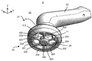
- FIG. 2 is a perspective view showing the appearance of the chestpiece observed from diagonally above.
- FIG. 3 is a perspective view showing the appearance of the chestpiece observed from diagonally below.
- FIG. 4 is a cross sectional view showing a cross section of the chest piece.
- FIG. 5 is a plan view showing the housing.
- FIG. 6 is a conceptual view showing how noise transmitted from the outside space to the inside space through the connection hole is canceled.
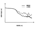
- FIG. 7 is a graph showing the difference in noise intensity depending on the presence or absence of the connection hole.
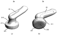
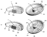
- FIG. 8 (a) is a perspective view showing the appearance of a chest piece with no communication hole formed, observed from diagonally above, and FIG.
- FIG. 8 (b) shows the communication hole formed with diagonally observed from the lower side It is a perspective view which shows the external appearance of no chest piece.
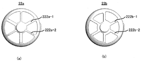
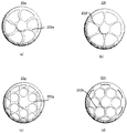
- FIG. 9A and FIG. 9B is a plan view showing a housing to which a first countermeasure is taken to prevent the resonance of the holding unit.
- FIGS. 10 (a) to 10 (d) is a plan view showing a case to which a second countermeasure is taken to prevent resonance of the holding unit.
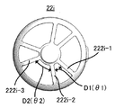
- FIG. 11 is a plan view showing a case to which a third countermeasure is taken to prevent resonance of the holding unit.
- FIG. 12A and FIG. 12B is a perspective view and a cross-sectional view showing a housing of the second modified example.
- FIG. 13 is a cross sectional view showing a cross section of the chest piece.
- the embodiment of the living body sound acquiring apparatus includes a first member, an acquiring unit for acquiring living body sound, and an internal space which is directly or indirectly connected to the first member and which is internally formed with the first member.
- a second member for holding the acquiring portion therein is provided, and each of the first and second members has a communicating portion for communicating the external space of the first and second members with the internal space.
- the noise generated in the external space is transmitted to the internal space and the second member via the communication part of the first member. Furthermore, the noise generated in the external space is transmitted to the internal space and the second member through the connecting portion of the second member. For this reason, the noise transmitted through the connecting portion of the first member and the noise transmitted through the connecting portion of the second member cancel each other in the internal space or the second member. As a result, noise transmitted to the second member and the acquisition unit via the internal space and noise transmitted to the acquisition unit via the second member are reduced. For this reason, the noise which an acquisition part acquires can be reduced effectively. That is, the embodiment of the living body sound acquisition apparatus can preferably acquire living body sound while reducing noise.
- the acquiring unit includes a vibration sensor, and the acquiring unit is configured to vibrate at least a part of the second member generated due to the living body sound.
- the body sound is acquired by detecting with a vibration sensor.
- the above-described effect can be appropriately obtained in the body sound acquiring apparatus that acquires body sound using such a vibration sensor.
- the communication unit includes a hole formed in at least one of the first and second members.
- the noise is relatively efficiently transmitted from the external space to the internal space and the second member through the hole as the communication part. For this reason, the noise transmitted through the connecting portion of the first member and the noise transmitted through the connecting portion of the second member cancel each other relatively efficiently in the internal space and the second member . Therefore, the above-described effects can be appropriately obtained.
- the communication portion includes a partition portion thinner than the other portion of at least one of the first and second members.
- the noise is relatively efficiently transmitted to the internal space and the second member from the external space through the partition wall serving as the connecting portion. For this reason, the noise transmitted through the connecting portion of the first member and the noise transmitted through the connecting portion of the second member cancel each other relatively efficiently in the internal space and the second member . Therefore, the above-described effects can be appropriately obtained.
- the second member includes a holding unit that holds the acquiring unit, a beam-like support unit that supports the holding unit, the holding unit, and the support. And the communication part whose outer edge is defined by the part.
- the acquisition unit is appropriately held by the holding unit.
- a relatively large communication portion can be secured.
- noise is relatively efficiently transmitted from the external space to the internal space and the second member through the relatively large communication part. For this reason, the noise transmitted through the connecting portion of the first member and the noise transmitted through the connecting portion of the second member cancel each other relatively efficiently in the internal space and the second member .
- the support can be deformed flexibly.
- the holding unit supported by such a support unit (further, the acquisition unit held by the holding unit) can maintain an appropriate posture according to the unevenness, inclination, and the like of the body surface of the living body.
- the second member includes the plurality of support portions having different natural frequencies.
- the resonance of the holding unit supported by the plurality of supports (further, the acquisition unit held by the holding unit) is appropriately prevented. For this reason, noise (in particular, noise caused by resonance of the holding unit) acquired by the acquisition unit is appropriately reduced.
- the second member described above has a support portion
- the second member has a plurality of the support portions different in at least one of length, width, thickness and elastic modulus.
- the natural frequencies of the plurality of support portions are different. Therefore, the resonance of the holding unit supported by the plurality of supports (further, the acquisition unit held by the holding unit) is appropriately prevented. For this reason, noise (in particular, noise caused by resonance of the holding unit) acquired by the acquisition unit is appropriately reduced.
- the second member described above has a support portion
- the second member has the support portion extending in a curvilinear shape, extending with a change in width or extending in a fork.
- the resonance of the holding portion (further, the acquisition portion held by the holding portion) is appropriately prevented as compared with the case where the linearly extending supporting portion having the uniform width supports the holding portion. For this reason, noise (in particular, noise caused by resonance of the holding unit) acquired by the acquisition unit is appropriately reduced.
- the second member described above has a support portion
- the second member has at least three support portions arranged at different arrangement intervals.
- the resonance of the holding unit (further, the acquisition unit held by the holding unit) is appropriately prevented compared to the case where the plurality of supporting units arranged at the same arrangement interval support the holding unit. Be done. For this reason, noise (in particular, noise caused by resonance of the holding unit) acquired by the acquisition unit is appropriately reduced.
- the second member described above has a support portion
- the second member intersects the support portion extending in a first direction along a predetermined plane, and the predetermined plane It has the said support part extended along 2 directions.
- the holding portion (further, the acquisition portion held by the holding portion) is supported not only by the support portion extending along the first direction but also by the support portion extending along the second direction. Therefore, the stability of the posture of the holding unit is improved.
- the embodiment of the living body sound acquiring apparatus includes the first member, the acquiring unit, and the second member, and the first and second members have the communicating unit. Therefore, the embodiment of the body sound acquisition apparatus can appropriately reduce the noise acquired by the acquisition unit.
- Example of the body sound acquisition apparatus of this invention is described.
- the description will be made using the electronic stethoscope 1 to which the embodiment of the living body sound acquiring apparatus of the present invention is applied.
- FIG. 1 is a block diagram showing an entire configuration of the electronic stethoscope 1 of the present embodiment.
- the electronic stethoscope 1 which is a specific example of the “body sound acquisition device” in the above-described embodiment is a vibration sensor 11 which is a specific example of the “acquisition unit” in the above-described embodiment;
- a band pass filter 12, a cutoff frequency adjustment unit 13, a power amplifier 14, a volume adjustment unit 15, and an earphone 16 are provided.
- the vibration sensor 11 is a sensor that can acquire body sounds (for example, breathing sounds) emitted from the living body 3.
- the vibration sensor 11 acquires a body sound by detecting a vibration (in other words, a displacement) of a holding plate 223 described later that is generated due to the body sound.
- An example of such a vibration sensor 11 is an acceleration sensor.
- the body sound signal indicating the body sound acquired by the vibration sensor 11 is output to the band pass filter 12.
- the band pass filter 12 is a filter that passes only a signal component of a desired frequency band in the biological sound signal input from the vibration sensor 11.
- the cutoff frequency blocked by the band pass filter 12 is adjusted by the cutoff frequency adjustment unit 13.
- the body sound signal that has passed through the band pass filter 12 is output to the power amplifier 14.
- the power amplifier 14 changes the strength of the body sound signal according to the set gain.
- the gain of the power amplifier 14 is adjusted by the volume adjustment unit 15.
- the body sound signal that has passed through the power amplifier 14 is output to the earphone 16.
- the earphone 16 outputs the body sound indicated by the body sound signal as a sound.
- the vibration sensor 11 is housed in a chest piece 2 of the electronic stethoscope 1.
- the chest piece 2 is a component pressed against the living body 3 for auscultation.
- the chest piece 2 has a structure capable of reducing noise acquired by the vibration sensor 11 (that is, a sound different from the biological sound to be acquired, for example, an environmental sound). There is.
- the structure of the chestpiece 2 will be further described.
- at least one of the band pass filter 12, the cutoff frequency adjustment unit 13, the power amplifier 14, and the volume adjustment unit 15 may be accommodated in the chest piece 2.
- FIG. 2 is a perspective view showing the appearance of the chest piece 2 observed from diagonally above.
- FIG. 3 is a perspective view showing the appearance of the chest piece 2 observed from diagonally below.
- FIG. 4 is a cross sectional view showing a cross section of the chest piece 2.
- the chest piece 2 is a housing 21 which is a specific example of the “first member” in the embodiment described above, and an example of the “second member” in the embodiment described above And a grip 23.
- the housing 21 includes a frame 211, a plurality of beams 212, and a frame 213.
- Each of the frames 211 and 213 is a cylindrical or ring-shaped member.
- Each of the plurality of beams 212 is a beam-like (in other words, rod-like) member extending from the frame 211 toward the frame 213.
- One end of each of the plurality of beams 212 is connected to the frame 211, and the other end of each of the plurality of beams 212 is connected to the frame 213.
- the plurality of beams 212 are arranged at the same interval in the circumferential direction of the frames 211 and 213, but may be arranged at different intervals.
- the frame 213 is connected to the grip 23 that the user grips when body sound is acquired.
- the housing 22 includes a frame 221, a plurality of beams 222, and a holding plate 223.
- a plan view of the housing 22 is shown in FIG.
- the frame 221 is a cylindrical or ring-shaped member.
- the frame 221 is directly connected to the frame 211 of the housing 21.
- the frame 221 may be indirectly connected to the frame 211 via an intermediate member.
- the cases 21 and 22 define an internal space 24 located inside the cases 21 and 22.
- Each of the plurality of beams 222 is a beam-like (in other words, rod-like) member extending from the frame 221 toward the center of the frame 221 (that is, the center of the circular opening defined by the frame 221). In other words, the plurality of beams 222 extend radially from the center of the frame 221.
- the plurality of beams 222 are preferably members having elasticity (for example, resin, metal, etc.).
- the plurality of beams 222 is preferably a member having flexibility (for example, resin, metal, etc.).
- the plurality of beams 222 are arranged at the same interval in the circumferential direction of the frames 221 and 223, but may be arranged at different intervals.
- each of the plurality of beams 222 is connected to the frame 221, and the other end of each of the plurality of beams 222 is connected to the holding plate 223.
- the holding plate 223 is a plate-like (in the example shown in FIGS. 2 to 3, a disk-like) member.
- the vibration sensor 11 is installed on the + Z side surface of the holding plate 223 (that is, the surface facing the internal space 24 and hereinafter referred to as “the back surface”). For this reason, the vibration sensor 11 is held by the holding plate 223 in the internal space 24.
- the surface on the ⁇ Z side of the holding plate 223 (that is, the surface not facing the internal space 24 and hereinafter referred to as “surface”) is a surface that is pressed against the body surface of the living body when the body sound is acquired. is there.
- a vibration corresponding to the body sound is generated in the holding plate 223.
- the vibration sensor 11 acquires body sound by detecting the vibration of the holding plate 223.
- the body sound signal indicating the body sound acquired by the vibration sensor 11 is output to the band pass filter 12 described above via a signal line set in a cavity or the like inside the grip 23.
- the housing 21 is further provided with a plurality of communication holes (i.e., openings or through holes) 214 which are one specific example of the "communication portion" in the above-described embodiment.
- Each communication hole 214 is surrounded by a frame 211, two beams 212 and a frame 213. That is, the outer edge of each communication hole 214 is defined by the frame 211, the two beams 212 and the frame 213.
- the shapes of the frame 211, the plurality of beams 212, and the frame 213 are designed such that the plurality of communication holes 214 are formed in the housing 21.
- the housing 22 is further provided with a plurality of holes (that is, openings or through holes) 224 which are each a specific example of the “communication portion” in the above-described embodiment.
- Each hole 224 is surrounded by the frame 221, two beams 222 and a holding plate 223. That is, the outer edge of each hole 224 is defined by the frame 221, the two beams 222 and the holding plate 223.
- the shapes of the frame 221, the two beams 222 and the holding plate 223 are designed such that a plurality of holes 224 are formed in the housing 22.
- the communication holes 214 connect the external space 25 located outside the housings 21 and 22 (that is, the external space located outside the chest piece 2) with the internal space 24 located inside the housings 21 and 22. doing.
- sound can be transmitted from the external space 25 to the internal space 24 through the communication hole 214.
- sound for example, noise
- the holding plate 223 in particular, the back surface thereof
- the sound for example, noise generated in the outer space 25 through the communication hole 214 is transmitted to the holding plate 223 (in particular, , Can be transmitted to the back).
- the communication hole 214 is formed in the housing 21 for transmitting sound from the outer space 25 to the inner space 24 (further, the member facing the inner space 24). Therefore, “communicating the outer space 25 with the inner space 24” in the present embodiment means “a sound (for example, noise) generated in the outer space 25 facing the inner space 24 (further, the inner space 24). Transmission to the corresponding member).
- the contact hole 224 also connects the outer space 25 and the inner space 24 in the same manner as the contact hole 214. Therefore, sound can be transmitted from the external space 25 to the internal space 24 not only through the communication hole 214 but also through the communication hole 224.
- FIG. 6 will be used to describe the technical effects that can be enjoyed by the electronic stethoscope 1 of the present embodiment (that is, the noise reduction effect acquired by the vibration sensor 11).
- FIG. 6 shows how noise transmitted from the outer space 25 to the inner space 24 through the communication hole 214 and noise transmitted from the outer space 25 to the inner space 24 through the communication hole 224 are canceled out. It is a conceptual diagram.
- noise for example, environmental sound, in particular, noise generated in the external space 25
- the holding plate 223 is vibrated not only by the body sound but also by the noise.
- much noise mixed with body sound is acquired by the vibration sensor 11 and closed. For this reason, there is a possibility that the diagnosis based on the body sound can not be accurately performed.
- the communication hole 214 is formed in the housing 21, and the communication hole 224 is formed in the housing 22.
- the noise generated in the external space 25 is transmitted to the holding plate 223 via the communication hole 214 (that is, via the electronic stethoscope 1).
- noise generated in the external space 25 is transmitted to the holding plate 223 via the communication hole 224 (that is, via the living body 3) (or some noise is not held via the communication hole 224) 223).
- the noise transmitted to the holding plate 223 via the communication hole 224 is transmitted via the inside of the living body 3 in comparison with the noise transmitted to the holding plate 223 via the communication hole 214. Due to that, its phase is reversed.
- the noise transmitted through the communication hole 214 and the noise transmitted through the communication hole 224 cancel each other.
- the vibration of the holding plate 223 caused by noise is weakened. Therefore, the noise which vibration sensor 11 acquires becomes small.
- the noise generated in the external space 25 is also transmitted to the internal space 24 through the communication holes 214 and 224 respectively. Therefore, also in the internal space 24, the noise transmitted through the communication hole 214 and the noise transmitted through the communication hole 224 cancel each other. For this reason, the noise itself propagating in the internal space 24 is also weakened. For this reason, the vibration of the holding plate 223 caused by the noise reaching the holding plate 223 via the internal space 24 is weakened. Therefore, the noise which vibration sensor 11 acquires becomes small.
- the body sound is transmitted to the surface of the holding plate 223. Therefore, unlike noise, body sounds are not canceled on the holding plate 223. That is, the body sound is acquired by the vibration sensor 11. As a result, in the vibration sensor 11, it is possible to preferably acquire the body sound in a state where the noise is reduced.
- the inventor of the present invention is an experiment of measuring the noise obtained when the holding plate 223 is pressed against the living body 3 in the state where the white noise is output from the external speaker Did.
- the intensity of the noise obtained by the experiment (that is, the intensity of the vibration of the vibration sensor 11, substantially the acceleration of the vibration sensor 11) is shown in FIG.
- dotted lines have chest pieces 2a (see FIGS. 8 (a) and 8 (b)) in which the communication holes 214 and 224 are not formed instead of the chess and piece 2 described above.
- strength of the surrounding noise acquired by the electronic stethoscope of the 1st comparative example is shown according to frequency.
- the solid line indicates the strength of the ambient noise acquired by the living body sound acquiring apparatus 1 of the present embodiment having all the communication holes 214 and 224 by frequency.
- the noise intensity acquired by the living body sound acquiring apparatus of the present embodiment (that is, the intensity of vibration)
- the acceleration was proved to be smaller. That is, it has been proved that the noise obtained by the vibration sensor 11 can be effectively reduced by forming the communication hole 214 in the housing 21 and forming the communication hole 224 in the housing 22.
- the reason why the intensity of the noise acquired by the electronic stethoscope of the first comparative example is increased is that the noise generated in the external space 25 is not retained in the internal space 24 or because the communication holes 214 and 224 are not formed. It is estimated that this is because the plate 223 does not cancel out.
- noise generated in the external space 25 is transmitted to the internal space 24 through the connection hole 214. If so, the noise may be detected directly as a sound by the microphone before canceling out the noise transmitted through the communication hole 224.
- the noise generated in the outer space 25 is transmitted to the inner space 24 through the communication hole 224, the noise is sounded by the microphone before being canceled with the noise transmitted through the communication hole 214. May be detected directly.
- the communication holes 214 and 224 are formed in the housings 21 and 22, respectively, the noise reduction effect obtained by the microphone may be reduced.
- noise is not detected directly as a sound by the vibration sensor 11. That is, in the electronic stethoscope 1 of the present embodiment, after the noise is once converted into the vibration of the holding plate 223, the vibration of the holding plate 223 is detected by the vibration sensor 11 as a parameter indicating the noise. Therefore, when the noise is converted into the vibration of the holding plate 223 (or before), the noise transmitted through the communication hole 214 (or the vibration due to the noise) and the vibration through the communication hole 224. The noise transmitted (or the vibration due to the noise) appropriately cancels out in the internal space 24 and the holding plate 223. Therefore, in the electronic stethoscope 1 of the present embodiment, the noise reduction effect acquired by the vibration sensor 11 is relatively high.
- each of the communication holes 214 and 224 is relative to each other. Is preferably large. According to the experiments of the inventors of the present application, it is confirmed that the larger the communication holes 214 and 224 are, the larger the noise reduction effect is. Therefore, it is preferable that each of the communication holes 214 and 224 have an appropriate size such that a noise reduction effect can be appropriately obtained.
- the beam 213 defining the outer edge of the communication hole 214 is a beam-like member. Therefore, it is advantageous in that relatively large communication holes 214 can be formed as compared with the case where the outer edge of the communication holes 214 is defined by a planar member. The same applies to the size of the communication hole 224.
- the reduction effect of the noise acquired by the vibration sensor 11 can be enjoyed as long as the communication holes 214 and 224 of any size are formed in the housings 21 and 22, respectively.
- the housing 21 may have any structure as long as at least one hole 214 is formed.
- the housing 22 may have any structure as long as at least one hole 224 is formed.
- the holding plate 223 pushes against the living body in order to obtain body sound.
- the plurality of beams 222 are flexibly deformed in accordance with the unevenness, inclination or the like of the body surface of the living body in contact with the holding plate 223.
- the holding plate 223 supported by such a plurality of beams 222 (furthermore, the vibration sensor 11 held by the holding plate 223) maintains an appropriate posture according to the unevenness, inclination, etc. of the body surface of the living body. can do.
- the holding plate 223 when the holding plate 223 is pressed against the body surface of the living body, the contact pressure to the body surface is required to some extent, so the holding plates 223 were pressed against the body surface of the living body In some cases, it is preferable to support the holding plate 223 in a state capable of applying a reaction force to the body surface of the living body.
- the holding plate 223 holding the vibration sensor 11 is supported by the plurality of beams 222.
- the holding plate 223 may resonate at a resonance frequency determined by the spring constants (or the elastic coefficients) of the plurality of beams 222 and the mass of the holding plate 223.
- the holding plate 223 resonates, vibration due to the resonance is detected by the vibration sensor 11, so the vibration sensor 11 acquires noise due to the resonance.
- the electronic stethoscope 1 (in particular, the chest piece 2) is provided with a measure for preventing the resonance of the holding plate 223 (that is, reducing the possibility of the holding plate 223 resonating). .
- the first to third measures for preventing the resonance of the holding plate 223 will be described in order.
- the housing 22 subjected to the first countermeasure As an example of the housing 22 subjected to the first countermeasure, as shown in FIG. 9A, at least two beams 222a-1 having different widths (that is, sizes along a direction perpendicular to the extending direction) are different from each other. And the housing 22a including the housing 222a-2.
- the housing 22 to which the first measure has been applied As an example of the housing 22 to which the first measure has been applied, as shown in FIG. 9B, at least two beams 222b-1 and 222b-having different lengths (that is, sizes along the extending direction) are used.
- the housing 22a is provided with two.
- An example of the housing 22 to which the first measure is applied is a housing 22c (not shown) having at least two beams 222c-1 and 222c-2 different in thickness from each other.
- the holding plate 223 extends linearly when all of the plurality of beams 222 have a uniform width. Is found to be easy to resonate. Therefore, as a second measure to prevent the resonance of the holding plate 223, it is possible to adopt a measure to make at least one of the plurality of beams 222 a shape different from a shape extending linearly with uniform width. is there.
- the housing 22 includes at least one beam 222 having a shape that is different from the linearly extending shape with a uniform width. As a result, the possibility of the holding plate 223 resonating is reduced as compared to the case where all the beams 222 extend in a uniform width and in a straight line. That is, the resonance of the holding plate 223 is appropriately prevented.
- FIG. 10A there is a housing 22e provided with at least one beam 222e extending in a curved shape.
- a housing 22f including at least one beam 222f which extends while changing in width can be mentioned.
- a housing 22g provided with at least one beam 222g which branches while extending in a curved shape can be mentioned.
- a housing 22h including at least one beam 222h which branches while extending in a straight line can be mentioned.
- the distribution is such that the plurality of beams 222 are arranged at equal angles (that is, at equal intervals). It has been found that the holding plate 223 easily resonates in the case of Therefore, as a third measure for preventing the resonance of the holding plate 223, the distance between the first beam 222 and the second beam 222 adjacent to the first beam 222 (that is, the first beam) (The angle between the second beam 222 and the second beam 222) and the distance between the second beam 222 and the third beam 222 adjacent to the second beam 222 (ie, the second beam 222 and the third beam 222) It is possible to adopt a measure to make the angle different from that of the beam 222 of For example, in the example shown in FIG.
- the distance D1 that is, the angle ⁇ 1 between the beam 222i-1 and the beam 222i-2 and the distance D2 between the beam 222i-2 and the beam 222i-3 ( That is, it is different from the angle ⁇ 2).
- the possibility of the holding plate 223 resonating is reduced as compared with the case where the plurality of beams 222 are distributed at equal angles. That is, the resonance of the holding plate 223 is appropriately prevented.
- the communication hole 224 for transmitting the noise of the external space 25 to the internal space 24 is formed in the housing 22.
- the noise of the external space 25 is added to the internal space of the housing 22j of the second modification.
- a partition 225 is formed for transfer to the housing 24. The thickness of the partition portion 225 is thinner than the thickness of a portion (for example, the beam 222) other than the partition portion 225 in the housing 22j.
- the partition wall 225 is formed in addition to or instead of the connection hole 224, the noise of the external space 25 is different from that of the partition wall 225 compared to the case where the partition wall 225 is not formed. It is easy to be transmitted to the internal space 24 via Therefore, the same effect as the effect described above can be obtained.
- a relatively thin partition may be formed to transmit the noise of the external space 25 to the internal space 24. .
- the holding plate 223 may be supported by the partition 225.
- the housing 22j may not include the plurality of beams 222.
- the housing 22 j may be provided with a plurality of beams 222.
- the holding plate 223 (further, the vibration sensor 11 held by the holding plate 223) is supported by the beam 222 extending along the same plane (for example, the XY plane) It is done.
- the holding plate 223 in addition to the beams 222 extending along the same plane (for example, the XY plane), the holding plate 223 has a predetermined direction crossing the plane ( For example, it is supported by an expandable spring 26k along the Z direction.
- one end of the spring 26k is connected to the holding plate 223 (or the vibration sensor 11), and the other end of the spring 26k is connected to the frame 213 of the housing 21 (or the beam 212 or other member of the housing 22). It is connected.
- the holding plate 223 when the holding plate 223 is pressed against the living body in order to obtain the living body sound, the holding plate 223 (further, the vibration sensor 11 held by the holding 223) is Thus, it is possible to more efficiently maintain an appropriate posture according to the unevenness, inclination and the like of the body surface of the living body.
- the function of the spring 26k is to support the holding plate 223 along the Z direction (that is, the direction intersecting the XY plane in which the beam 222 supports the holding plate 223).
- the chestpiece 2k may be provided with a support that supports the holding plate 223 along the Z direction in addition to or instead of the spring 26k.
- the member for example, resin, metal, etc.
- the support may be a beam-like member similar to the beam 222.
- the support may support the holding plate 223 without contacting the holding plate 223.
- the support portion may support the holding plate 223 using an electromagnetic force, an electrostatic force, or the like.
- the chest piece 2k also includes a support that supports the holding plate 223 along the XY plane, in addition to or instead of the beam 222. It may be This is applicable not only to the third modification but to all the embodiments described above.
- a member for example, a spring which contacts the holding part 223 and supports the holding part 223, and a member which supports the holding part 223 without contacting the holding part 223 can be mentioned.
Landscapes
- Physics & Mathematics (AREA)
- Acoustics & Sound (AREA)
- Health & Medical Sciences (AREA)
- Life Sciences & Earth Sciences (AREA)
- Molecular Biology (AREA)
- Biomedical Technology (AREA)
- Heart & Thoracic Surgery (AREA)
- Medical Informatics (AREA)
- Engineering & Computer Science (AREA)
- Surgery (AREA)
- Animal Behavior & Ethology (AREA)
- General Health & Medical Sciences (AREA)
- Public Health (AREA)
- Veterinary Medicine (AREA)
- Details Of Audible-Bandwidth Transducers (AREA)
- Soundproofing, Sound Blocking, And Sound Damping (AREA)
Abstract
生体音取得装置(1)は、第1部材(21)と、生体音を取得する取得部(11)と、第1部材に接続され、且つ、第1部材と共に内部に形成する内部空間(24)内に取得部を保持する第2部材(22)とを備え、第1及び第2部材の夫々は、第1及び第2部材の外部空間(25)と内部空間とを連絡させる連絡部(214、224)を有する。
Description
本発明は、例えば電子聴診器等の生体音取得装置の技術分野に関する。
特許文献1には、物体中の振動を収集して電気信号として出力する振動収集部と、振動収集部を覆う振動減衰容器とを備える生体音取得装置が記載されている。特許文献1に記載された生体音取得装置では、振動減衰容器により、振動収集部に到達する目的外振動(いわゆる、雑音)が低減される。
上述した特許文献1に記載された生体音取得装置は、振動減衰容器で雑音を遮断することで、振動収集部に到達する雑音の低減を図っている。しかしながら、本願発明者等の研究によれば、生体音を取得するための取得部を容器で覆うことで取得部が取得する雑音を低減する方法では、雑音を十二分に低減することが困難であることが判明した。そこで、本発明は、生体音を取得するための取得部が取得する雑音をより適切に低減することが可能な生体音取得装置を提供することを課題とする。
生体音取得装置の第1の態様は、第1部材と、生体音を取得する取得部と、前記第1部材に直接的又は間接的に接続され、且つ、前記第1部材と共に内部に形成する内部空間内に前記取得部を保持する第2部材とを備え、前記第1及び第2部材の夫々は、前記第1及び第2部材の外部空間と前記内部空間とを連絡させる連絡部を有する。
本発明の生体音取得装置に係る実施形態について説明する。
<1>
生体音取得装置の実施形態は、第1部材と、生体音を取得する取得部と、前記第1部材に直接的又は間接的に接続され、且つ、前記第1部材と共に内部に形成する内部空間内に前記取得部を保持する第2部材とを備え、前記第1及び第2部材の夫々は、前記第1及び第2部材の外部空間と前記内部空間とを連絡させる連絡部を有する。
生体音取得装置の実施形態は、第1部材と、生体音を取得する取得部と、前記第1部材に直接的又は間接的に接続され、且つ、前記第1部材と共に内部に形成する内部空間内に前記取得部を保持する第2部材とを備え、前記第1及び第2部材の夫々は、前記第1及び第2部材の外部空間と前記内部空間とを連絡させる連絡部を有する。
生体音取得装置の実施形態によれば、外部空間で発生する雑音が、第1部材の連絡部を介して、内部空間や第2部材に伝達される。更に、外部空間で発生する雑音は、第2部材の連絡部を介して、内部空間や第2部材に伝達される。このため、第1部材の連絡部を介して伝達される雑音と、第2部材の連絡部を介して伝達される雑音とは、内部空間や第2部材において相殺し合う。その結果、内部空間を介して第2部材及び取得部に伝達される雑音や、第2部材を介して取得部に伝達される雑音が低減される。このため、取得部が取得する雑音を効果的に低減できる。つまり、生体音取得装置の実施形態は、雑音を低減しつつ、好適に生体音を取得することができる。
<2>
上述した生体音取得装置の実施形態の他の態様では、前記取得部は、振動センサを含み、前記取得部は、生体音に起因して発生する前記第2部材の少なくとも一部の振動を前記振動センサで検出することで、前記生体音を取得する。
上述した生体音取得装置の実施形態の他の態様では、前記取得部は、振動センサを含み、前記取得部は、生体音に起因して発生する前記第2部材の少なくとも一部の振動を前記振動センサで検出することで、前記生体音を取得する。
この態様によれば、このような振動センサを用いて生体音を取得する生体音取得装置において、上述した効果が適切に享受できる。
<3>
上述した生体音取得装置の実施形態の他の態様では、前記連絡部は、前記第1及び第2部材の少なくとも一方に形成された孔を含む。
上述した生体音取得装置の実施形態の他の態様では、前記連絡部は、前記第1及び第2部材の少なくとも一方に形成された孔を含む。
この態様によれば、雑音は、外部空間から、連絡部としての孔を介して内部空間や第2部材に相対的に効率的に伝達される。このため、第1部材の連絡部を介して伝達される雑音と、第2部材の連絡部を介して伝達される雑音とは、内部空間や第2部材において相対的に効率的に相殺し合う。従って、上述した効果が適切に享受できる。
<4>
上述した生体音取得装置の実施形態の他の態様では、前記連絡部は、前記第1及び第2部材の少なくとも一方の他の部分よりも薄い隔壁部を含む。
上述した生体音取得装置の実施形態の他の態様では、前記連絡部は、前記第1及び第2部材の少なくとも一方の他の部分よりも薄い隔壁部を含む。
この態様によれば、雑音は、外部空間から、連絡部としての隔壁部を介して内部空間や第2部材に相対的に効率的に伝達される。このため、第1部材の連絡部を介して伝達される雑音と、第2部材の連絡部を介して伝達される雑音とは、内部空間や第2部材において相対的に効率的に相殺し合う。従って、上述した効果が適切に享受できる。
<5>
上述した生体音取得装置の実施形態の他の態様では、前記第2部材は、前記取得部を保持する保持部と、前記保持部を支持する梁状の支持部と、前記保持部及び前記支持部によって外縁が規定される前記連絡部とを有する。
上述した生体音取得装置の実施形態の他の態様では、前記第2部材は、前記取得部を保持する保持部と、前記保持部を支持する梁状の支持部と、前記保持部及び前記支持部によって外縁が規定される前記連絡部とを有する。
この態様によれば、保持部によって、取得部が適切に保持される。
更に、梁状の支持部で保持部を支持することで、相対的に大きな連絡部が確保可能となる。その結果、雑音は、外部空間から、相対的に大きな連絡部を介して内部空間や第2部材に相対的に効率的に伝達される。このため、第1部材の連絡部を介して伝達される雑音と、第2部材の連絡部を介して伝達される雑音とは、内部空間や第2部材において相対的に効率的に相殺し合う。
更に、支持部が梁状であるがゆえに、生体音を取得するために第2部材が生体に押し当てられた際に、第2部材と接触する生体の体表の凹凸や傾き等に応じて、支持部が柔軟に変形し得る。その結果、このような支持部によって支持される保持部(更には、保持部が保持する取得部)は、生体の体表の凹凸や傾き等に応じた適切な姿勢を維持することができる。
<6>
上述した第2部材が支持部を有する生体音取得装置の他の態様では、前記第2部材は、固有振動数が異なる複数の前記支持部を有する。
上述した第2部材が支持部を有する生体音取得装置の他の態様では、前記第2部材は、固有振動数が異なる複数の前記支持部を有する。
この態様によれば、複数の支持部によって支持される保持部(更には、保持部が保持する取得部)の共振が適切に防止される。このため、取得部が取得する雑音(特に、保持部の共振に起因した雑音)が適切に低減される。
<7>
上述した第2部材が支持部を有する生体音取得装置の他の態様では、前記第2部材は、長さ、幅、厚さ及び弾性係数の少なくとも一つが異なる複数の前記支持部を有する。
上述した第2部材が支持部を有する生体音取得装置の他の態様では、前記第2部材は、長さ、幅、厚さ及び弾性係数の少なくとも一つが異なる複数の前記支持部を有する。
この態様によれば、複数の支持部の固有振動数が異なる。従って、複数の支持部によって支持される保持部(更には、保持部が保持する取得部)の共振が適切に防止される。このため、取得部が取得する雑音(特に、保持部の共振に起因した雑音)が適切に低減される。
<8>
上述した第2部材が支持部を有する生体音取得装置の他の態様では、前記第2部材は、曲線状に延びる、幅が変化しながら延びる又は分岐しながら延びる前記支持部を有する。
上述した第2部材が支持部を有する生体音取得装置の他の態様では、前記第2部材は、曲線状に延びる、幅が変化しながら延びる又は分岐しながら延びる前記支持部を有する。
この態様によれば、均一幅で直線状に延びる支持部が保持部を支持する場合と比較して、保持部(更には、保持部が保持する取得部)の共振が適切に防止される。このため、取得部が取得する雑音(特に、保持部の共振に起因した雑音)が適切に低減される。
<9>
上述した第2部材が支持部を有する生体音取得装置の他の態様では、前記第2部材は、前記第2部材は、異なる配置間隔で配置される少なくとも3つの前記支持部を有する。
上述した第2部材が支持部を有する生体音取得装置の他の態様では、前記第2部材は、前記第2部材は、異なる配置間隔で配置される少なくとも3つの前記支持部を有する。
この態様によれば、同一の配置間隔で配置される複数の支持部が保持部を支持する場合と比較して、保持部(更には、保持部が保持する取得部)の共振が適切に防止される。このため、取得部が取得する雑音(特に、保持部の共振に起因した雑音)が適切に低減される。
<10>
上述した第2部材が支持部を有する生体音取得装置の他の態様では、前記第2部材は、所定平面に沿った第1方向に沿って延びる前記支持部と、前記所定平面に交差する第2方向に沿って延びる前記支持部を有する。
上述した第2部材が支持部を有する生体音取得装置の他の態様では、前記第2部材は、所定平面に沿った第1方向に沿って延びる前記支持部と、前記所定平面に交差する第2方向に沿って延びる前記支持部を有する。
この態様によれば、保持部(更には、保持部が保持する取得部)は、第1方向に沿って延びる支持部のみならず、第2方向に沿って延びる支持部によっても支持される。このため、保持部の姿勢の安定性が向上する。
以上説明したように、生体音取得装置の実施形態は、第1部材と、取得部と、第2部材とを備え、第1及び第2部材は連絡部を有する。従って、生体音取得装置の実施形態は、取得部が取得する雑音を適切に低減することができる。
続いて、本発明の生体音取得装置の実施例について説明する。以下では、本発明の生体音取得装置の実施例が適用された電子聴診器1を用いて説明を進める。
(1)電子聴診器1の全体構成
はじめに、図1を参照しながら、本実施例の電子聴診器1の全体構成について説明する。図1は、本実施例の電子聴診器1の全体構成を示すブロック図である。
はじめに、図1を参照しながら、本実施例の電子聴診器1の全体構成について説明する。図1は、本実施例の電子聴診器1の全体構成を示すブロック図である。
図1に示すように、上述した実施形態における「生体音取得装置」の一具体例である電子聴診器1は、上述した実施形態における「取得部」の一具体例である振動センサ11と、バンドパスフィルタ12と、遮断周波数調整部13と、パワーアンプ14と、音量調整部15と、イヤフォン16とを備えている。
振動センサ11は、生体3から発せられる生体音(例えば、呼吸音等)を取得可能なセンサである。本実施例では、振動センサ11は、生体音に起因して発生する後述する保持板223の振動(言い換えれば、変位)を検出することで、生体音を取得する。このような振動センサ11の一例として、加速度センサがあげられる。振動センサ11で取得された生体音を示す生体音信号は、バンドパスフィルタ12に出力される。バンドパスフィルタ12は、振動センサ11から入力される生体音信号のうち、所望の周波数帯域の信号成分のみを通過させるフィルタである。バンドパスフィルタ12で遮断される遮断周波数は、遮断周波数調整部13によって調整される。バンドパスフィルタ12を通過した生体音信号は、パワーアンプ14に出力される。パワーアンプ14は、生体音信号の強度を、設定されたゲインに応じて変化させる。パワーアンプ14のゲインは、音量調整部15によって調整される。パワーアンプ14を通過した生体音信号は、イヤフォン16に出力される。イヤフォン16は、生体音信号が示す生体音を音として出力する。
振動センサ11は、電子聴診器1のチェストピース2に収容される。チェストピース2は、聴診のために生体3に押し当てられる部品である。本実施例では、チェストピース2は、振動センサ11が取得する雑音(つまり、取得対象である生体音とは異なる音であり、例えば環境音等)を低減することが可能な構造を有している。以下、チェストピース2の構造について更に説明を進める。尚、振動センサ11に加えて、バンドバスフィルタ12、遮断周波数調整部13、パワーアンプ14及び音量調整部15の少なくとも一つが、チェストピース2に収容されていてもよい。
(2)電子聴診器1のチェストピース2の構造
続いて、図2から図4を参照しながら、電子聴診器1のチェストピース2の構造について説明する。図2は、斜め上方から観察したチェストピース2の外観を示す斜視図である。図3は、斜め下方から観察したチェストピース2の外観を示す斜視図である。図4は、チェストピース2の断面を示す断面図である。
続いて、図2から図4を参照しながら、電子聴診器1のチェストピース2の構造について説明する。図2は、斜め上方から観察したチェストピース2の外観を示す斜視図である。図3は、斜め下方から観察したチェストピース2の外観を示す斜視図である。図4は、チェストピース2の断面を示す断面図である。
図2から図4に示すように、チェストピース2は、上述した実施形態における「第1部材」の一具体例である筐体21と、上述した実施形態における「第2部材」の一具体例である筐体22と、グリップ23とを備える。
筐体21は、フレーム211と、複数の梁212と、フレーム213とを備える。フレーム211及び213の夫々は、円筒状又はリング状の部材である。複数の梁212の夫々は、フレーム211からフレーム213に向かって延びる梁状の(言いかえれば、棒状の)部材である。複数の梁212の夫々の一端は、フレーム211に連結され、複数の梁212の夫々の他端は、フレーム213に連結される。複数の梁212は、フレーム211及び213の周方向において同一間隔で並ぶが、異なる間隔で並んでいてもよい。フレーム213は、生体音が取得される際にユーザが掴むグリップ23に連結される。
筐体22は、フレーム221と、複数の梁222と、保持板223とを備える。尚、図5に、筐体22の平面図を示す。フレーム221は、円筒状又はリング状の部材である。フレーム221は、筐体21のフレーム211に直接的に接続される。但し、フレーム221は、フレーム211との間に中間部材を介して間接的に接続されてもよい。筐体21と筐体22とが接続される結果、筐体21及び22は、筐体21及び22の内部に位置する内部空間24を規定する。
複数の梁222の夫々は、フレーム221からフレーム221の中心(つまり、フレーム221が規定する円形の開口の中心)に向かって延びる梁状の(言いかえれば、棒状の)部材である。言い換えれば、複数の梁222は、フレーム221の中心から放射状に広がる。複数の梁222は、弾性を有する部材(例えば、樹脂や金属等)であることが好ましい。複数の梁222は、柔軟性を有する部材(例えば、樹脂や金属等)であることが好ましい。複数の梁222は、フレーム221及び223の周方向において同一間隔で並ぶが、異なる間隔で並んでいてもよい。複数の梁222の夫々の一端は、フレーム221に連結され、複数の梁222の夫々の他端は、保持板223に連結される。従って、複数の梁212は、保持板223を支持する。保持板223は、板状(図2から図3に示す例では、円板状)の部材である。保持板223の+Z側の面(つまり、内部空間24に面する面であり、以降、“裏面”と称する)には、振動センサ11が設置される。このため、振動センサ11は、内部空間24内において保持板223によって保持される。
保持板223の-Z側の面(つまり、内部空間24に面しない面であり、以降、“表面”と称する)は、生体音が取得される際に生体の体表に押し当てられる面である。保持板223が生体の体表に押し当てられると、生体音に応じた振動が保持板223に生ずる。振動センサ11は、この保持板223の振動を検出することで、生体音を取得する。振動センサ11が取得した生体音を示す生体音信号は、グリップ23の内部の空洞等に設定された信号線を介して、上述したバンドパスフィルタ12へと出力される。
筐体21には更に、夫々が上述した実施形態における「連絡部」の一具体例である複数の連絡孔(つまり、開口ないしは貫通孔)214が形成されている。各連絡孔214は、フレーム211、2つの梁212及びフレーム213によって囲まれている。つまり、各連絡孔214の外縁は、フレーム211、2つの梁212及びフレーム213によって規定されている。逆に言えば、フレーム211、複数の梁212及びフレーム213の形状は、複数の連絡孔214が筐体21に形成されるように設計されている。
筐体22には更に、夫々が上述した実施形態における「連絡部」の一具体例である複数の孔(つまり、開口ないしは貫通孔)224が形成されている。各孔224は、フレーム221、2つの梁222及び保持板223によって囲まれている。つまり、各孔224の外縁は、フレーム221、2つの梁222及び保持板223によって規定されている。逆に言えば、フレーム221、2つの梁222及び保持板223の形状は、複数の孔224が筐体22に形成されるように設計されている。
連絡孔214は、筐体21及び22の外部に位置する外部空間(つまり、チェストピース2の外部に位置する外部空間)25と、筐体21及び22の内部に位置する内部空間24とを連絡している。連絡孔214が外部空間25と内部空間24とを連絡した結果、連絡孔214を介して、外部空間25から内部空間24に対して音が伝達可能となる。例えば、連絡孔214を介して、外部空間25で生じた音(例えば、雑音)が、内部空間24にも伝達可能となる。更には、内部空間24に保持板223(特に、その裏面)が面しているがゆえに、連絡孔214を介して、外部空間25で生じた音(例えば、雑音)が、保持板223(特に、その裏面)にも伝達可能となる。つまり、連絡孔214は、外部空間25から内部空間24(更には、内部空間24に面している部材)に対して音を伝達するために筐体21に形成される。従って、本実施例における「外部空間25と内部空間24とを連絡する」ことは、「外部空間25で生じた音(例えば、雑音)を内部空間24(更には、内部空間24に面している部材)に伝達させる」ことと実質的に等価である。
連絡孔224もまた、連絡孔214と同様に、外部空間25と内部空間24とを連絡している。従って、連絡孔214のみならず、連絡孔224を介しても、外部空間25から内部空間24に対して音が伝達可能となる。
(3)振動センサ11が取得する雑音の低減効果
次に、本実施例の電子聴診器1が享受可能な技術的効果(つまり、振動センサ11が取得する雑音の低減効果)について、図6を参照して説明する。図6は、連絡孔214を介して外部空間25から内部空間24に伝達される雑音と、連絡孔224を介して外部空間25から内部空間24に伝達される雑音とが相殺される様子を示す概念図である。
次に、本実施例の電子聴診器1が享受可能な技術的効果(つまり、振動センサ11が取得する雑音の低減効果)について、図6を参照して説明する。図6は、連絡孔214を介して外部空間25から内部空間24に伝達される雑音と、連絡孔224を介して外部空間25から内部空間24に伝達される雑音とが相殺される様子を示す概念図である。
図6に示すように、生体3からは、取得すべき生体音と共に雑音(例えば、環境音であり、特に、外部空間25で生じた雑音)が保持板223に伝達される。このため、仮に何らの対策も施さなければ(具体的には、連絡孔214及び224が形成されなければ)、保持板223は、生体音のみならず雑音によっても振動してしまう。その結果、生体音に混じって多くの雑音が振動センサ11によって取得されてしまる。このため、生体音に基づく診断等を正確に行えなくなってしまうおそれがある。
しかるに本実施例では、既に説明したように、筐体21に連絡孔214が形成されており、且つ、筐体22に連絡孔224が形成されている。このため、図6に示すように、外部空間25で生じた雑音は、連絡孔214を介して(つまり、電子聴診器1を介して)保持板223に伝達される。更に、外部空間25で生じた雑音は、連絡孔224を介して(つまり、生体3を介して)保持板223に伝達される(或いは、一部の雑音は連絡孔224を介することなく保持板223に伝達される)。ここで、連絡孔224を介して保持板223に伝達される雑音は、連絡孔214を介して保持板223に伝達される雑音と比較して、生体3の内部を介して伝達されることに起因して、その位相が反転している。このため、保持板223上において、連絡孔214を介して伝達される雑音と、連絡孔224を介して伝達される雑音とが相殺し合う。その結果、雑音に起因する保持板223の振動が弱められる。従って、振動センサ11が取得する雑音は小さくなる。
更に、外部空間25で生じた雑音は、連絡孔214及び224の夫々を介して、内部空間24にも伝達される。このため、内部空間24においても、連絡孔214を介して伝達される雑音と、連絡孔224を介して伝達される雑音とが相殺し合う。このため、内部空間24内を伝搬する雑音自体も弱められる。このため、内部空間24を介して保持板223に到達する雑音に起因する保持板223の振動が弱められる。従って、振動センサ11が取得する雑音は小さくなる。
一方で、生体音については、保持板223の表面に伝達される。このため、雑音とは異なって、生体音は、保持板223上で相殺されることはない。つまり、生体音は、振動センサ11で取得される。この結果、振動センサ11では、雑音が低減された状態で、好適に生体音を取得することが可能となる。
このような雑音の低減効果を具体的に検証するために、本願発明者は、外部スピーカーからホワイトノイズを出力した状態で保持板223を生体3に押し当てた時に取得される雑音を測定する実験を行った。実験によって得られた雑音の強度(つまり、振動センサ11の振動の強度であり、実質的には、振動センサ11の加速度)が図7に示されている。具体的には、図7において、点線は、上述したチェスとピース2に代えて連絡孔214及び224が形成されていないチェストピース2a(図8(a)及び図8(b)参照)を備える第1比較例の電子聴診器によって取得された周辺雑音の強度を、周波数別に示す。更に、図7において、実線は、連絡孔214及び224の全てを有する本実施例の生体音取得装置1によって取得された周辺雑音の強度を、周波数別に示す。
図7に示すように、第1比較例の電子聴診器によって取得された雑音の強度と比較して、本実施例の生体音取得装置によって取得された雑音の強度(つまり、振動の強度であり、加速度)が小さくなることが実証された。つまり、連絡孔214を筐体21に形成し且つ連絡孔224を筐体22に形成することで、振動センサ11が取得する雑音を効果的に低減可能であることが実証された。尚、第1比較例の電子聴診器によって取得された雑音の強度が大きくなる理由は、連絡孔214及び224が形成されていないがゆえに、外部空間25で生じた雑音が、内部空間24や保持板223において相殺されないからであると推定される。
尚、振動センサ11に代えて生体音を音として直接的に検出するマイクロフォンを備える第2比較例の電子聴診器では、外部空間25で生じた雑音が連絡孔214を介して内部空間24に伝達されると、当該雑音は、連絡孔224を介して伝達される雑音と相殺される前に、マイクロフォンによって音として直接的に検出されてしまう可能性がある。同様に、外部空間25で生じた雑音が連絡孔224を介して内部空間24に伝達されると、当該雑音は、連絡孔214を介して伝達される雑音と相殺される前に、マイクロフォンによって音として直接的に検出されてしまう可能性がある。このため、第2比較例の電子聴診器では、筐体21及び22に夫々連絡孔214及び224が形成されると、マイクロフォンが取得する雑音の低減効果が薄れる可能性がある。しかるに、振動センサ11を備える本実施例の電子聴診器1では、雑音が振動センサ11によって音として直接的に検出されることはない。つまり、本実施例の電子聴診器1では、雑音が保持板223の振動に一旦変換された後に、保持板223の振動が雑音を示すパラメータとして振動センサ11によって検出されることになる。このため、雑音が保持板223の振動に変換される際に(或いは、前に)、連絡孔214を介して伝達される雑音(或いは、当該雑音に起因した振動)と、連絡孔224を介して伝達される雑音(或いは、当該雑音に起因した振動)とは、内部空間24や保持板223において適切に相殺し合う。従って、本実施例の電子聴診器1では、振動センサ11が取得する雑音の低減効果が相対的に高くなる。
尚、外部空間25で生じた雑音を連絡孔214及び224を介して内部空間24に伝達することで雑音の低減効果が得られることを考慮すれば、連絡孔214及び224の夫々は、相対的に大きいことが好ましい。尚、本願発明者等の実験によって、連絡孔214及び224の夫々が大きくなればなるほど、雑音の低減効果が大きくなることが確認されている。従って、連絡孔214及び224の夫々は、雑音の低減効果が適切に得られるような適切な大きさを有することが好ましい。
このような連絡孔214の大きさに関して、本実施例では、連絡孔214の外縁を規定する梁213は、梁状の部材である。このため、連絡孔214の外縁が面状の部材によって規定される場合と比較して、相対的に大きな連絡孔214が形成可能という点で有益である。連絡孔224の大きさについても同様である。但し、振動センサ11が取得する雑音の低減効果は、任意の大きさの連絡孔214及び224が任意の数だけ夫々筐体21及び22に形成されている限りは享受可能である。このため、筐体21は、少なくとも一つの孔214が形成されている限りはどのような構造を有していてもよい。同様に、筐体22は、少なくとも一つの孔224が形成されている限りはどのような構造を有していてもよい。
また、梁222が梁状の部材である(更には、弾性や柔軟性を有する部材である)ことに関連して、本実施例では、生体音を取得するために保持板223が生体に押し当てられた際に、保持板223と接触する生体の体表の凹凸や傾き等に応じて、複数の梁222が柔軟に変形する。その結果、このような複数の梁222によって支持される保持板223(更には、保持板223が保持する振動センサ11)は、生体の体表の凹凸や傾き等に応じた適切な姿勢を維持することができる。尚、保持板223を生体の体表に押し当てたときに当該体表への接触圧がある程度必要であることから、複数の梁222は、保持板223が生体の体表に押し当てられた場合に生体の体表に対して反力を付与することが可能な状態で保持板223を支持していることが好ましい。
(4)変形例
(4-1)第1変形例
上述したように、振動センサ11を保持する保持板223は、複数の梁222によって支持されている。この場合、保持板223は、複数の梁222のバネ定数(或いは、弾性係数)と保持板223の質量とで定まる共振周波数で共振する可能性がある。保持板223が共振すると、共振に起因した振動が振動センサ11によって検出されるがゆえに、振動センサ11は、共振に起因した雑音を取得してしまう。
(4-1)第1変形例
上述したように、振動センサ11を保持する保持板223は、複数の梁222によって支持されている。この場合、保持板223は、複数の梁222のバネ定数(或いは、弾性係数)と保持板223の質量とで定まる共振周波数で共振する可能性がある。保持板223が共振すると、共振に起因した振動が振動センサ11によって検出されるがゆえに、振動センサ11は、共振に起因した雑音を取得してしまう。
そこで、第1変形例では、保持板223の共振を防止する(つまり、保持板223が共振する可能性を小さくする)ための対策が電子聴診器1(特に、チェストピース2)に施される。以下、保持板223の共振を防止するための第1の対策から第3の対策について順に説明する。
(4-1-1)保持板223の共振を防止するための第1の対策
保持板223の共振を防止するための第1の対策として、複数の梁222のうちの少なくとも2つの梁222の固有振動数を異ならしめる対策が採用可能である。この場合、筐体22は、固有振動数が互いに異なる少なくとも2つの梁222を備える。その結果、複数の梁222の固有振動数が全て同一である場合と比較して、保持板223が共振する可能性が小さくなる。つまり、保持板223の共振が適切に防止される。
保持板223の共振を防止するための第1の対策として、複数の梁222のうちの少なくとも2つの梁222の固有振動数を異ならしめる対策が採用可能である。この場合、筐体22は、固有振動数が互いに異なる少なくとも2つの梁222を備える。その結果、複数の梁222の固有振動数が全て同一である場合と比較して、保持板223が共振する可能性が小さくなる。つまり、保持板223の共振が適切に防止される。
第1の対策が施された筐体22の一例として、図9(a)に示すように、幅(つまり、延伸方向に直交する方向に沿ったサイズ)が互いに異なる少なくとも2つの梁222a-1及び222a-2を備える筐体22aがあげられる。第1の対策が施された筐体22の一例として、図9(b)に示すように、長さ(つまり、延伸方向に沿ったサイズ)が互いに異なる少なくとも2つの梁222b-1及び222b-2を備える筐体22aがあげられる。第1の対策が施された筐体22の一例として、図示しないものの、厚さが互いに異なる少なくとも2つの梁222c-1及び222c-2を備える筐体22cがあげられる。第1の対策が施された筐体22の一例として、図示しないものの、弾性係数が互いに異なる少なくとも2つの梁222d-1及び222d-2を備える筐体22dがあげられる。
(4-1-2)保持板223の共振を防止するための第2の対策
本願発明者等の実験によれば、複数の梁222の全てが均一幅で直線状に延びる場合に保持板223が共振しやすくなることが判明している。そこで、保持板223の共振を防止するための第2の対策として、複数の梁222のうちの少なくとも一つの形状を、均一幅で直線状に延びる形状とは異なる形状にする対策が採用可能である。この場合、筐体22は、均一幅で直線状に延びる形状とは異なる形状を有する少なくとも一つの梁222を備える。その結果、複数の梁222の全てが均一幅で且つ直線状に延びる場合と比較して、保持板223が共振する可能性が小さくなる。つまり、保持板223の共振が適切に防止される。
本願発明者等の実験によれば、複数の梁222の全てが均一幅で直線状に延びる場合に保持板223が共振しやすくなることが判明している。そこで、保持板223の共振を防止するための第2の対策として、複数の梁222のうちの少なくとも一つの形状を、均一幅で直線状に延びる形状とは異なる形状にする対策が採用可能である。この場合、筐体22は、均一幅で直線状に延びる形状とは異なる形状を有する少なくとも一つの梁222を備える。その結果、複数の梁222の全てが均一幅で且つ直線状に延びる場合と比較して、保持板223が共振する可能性が小さくなる。つまり、保持板223の共振が適切に防止される。
第2の対策が施された筐体22の一例として、図10(a)に示すように、曲線状に延びる少なくとも一つの梁222eを備える筐体22eがあげられる。第2の対策が施された筐体22の一例として、図10(b)に示すように、幅が変化しながら延びる少なくとも一つの梁222fを備える筐体22fがあげられる。第2の対策が施された筐体22の一例として、図10(c)に示すように、曲線状に延びながら分岐する少なくとも一つの梁222gを備える筐体22gがあげられる。第2の対策が施された筐体22の一例として、図10(d)に示すように、直線状に延びながら分岐する少なくとも一つの梁222hを備える筐体22hがあげられる。
(4-1-3)保持板223の共振を防止するための第3の対策
本願発明者等の実験によれば、複数の梁222が等角度に(つまり、等間隔に)並ぶように分布する場合に保持板223が共振しやすくなることが判明している。そこで、保持板223の共振を防止するための第3の対策として、第1の梁222と当該第1の梁222に隣接する第2の梁222との間の間隔(つまり、第1の梁222と第2の梁222とがなす角度)と、第2の梁222と当該第2の梁222に隣接する第3の梁222との間の間隔(つまり、第2の梁222と第3の梁222とがなす角度)とを異ならしめる対策が採用可能である。例えば、図11に示す例で言えば、梁222i-1と梁222i-2との間の間隔D1(つまり、角度θ1)と、梁222i-2と梁222i-3との間の間隔D2(つまり、角度θ2)とが異なっている。その結果、複数の梁222が等角度に分布する場合と比較して、保持板223が共振する可能性が小さくなる。つまり、保持板223の共振が適切に防止される。
本願発明者等の実験によれば、複数の梁222が等角度に(つまり、等間隔に)並ぶように分布する場合に保持板223が共振しやすくなることが判明している。そこで、保持板223の共振を防止するための第3の対策として、第1の梁222と当該第1の梁222に隣接する第2の梁222との間の間隔(つまり、第1の梁222と第2の梁222とがなす角度)と、第2の梁222と当該第2の梁222に隣接する第3の梁222との間の間隔(つまり、第2の梁222と第3の梁222とがなす角度)とを異ならしめる対策が採用可能である。例えば、図11に示す例で言えば、梁222i-1と梁222i-2との間の間隔D1(つまり、角度θ1)と、梁222i-2と梁222i-3との間の間隔D2(つまり、角度θ2)とが異なっている。その結果、複数の梁222が等角度に分布する場合と比較して、保持板223が共振する可能性が小さくなる。つまり、保持板223の共振が適切に防止される。
(4-2)第2変形例
上述した説明では、筐体22には、外部空間25の雑音を内部空間24に伝達するための連絡孔224が形成されている。しかしながら、図12(a)及び図12(b)に示すように、第2変形例の筐体22jには、連絡孔224に代えて(或いは、加えて)、外部空間25の雑音を内部空間24に伝達するための隔壁部225が形成されている。隔壁部225の厚さは、筐体22jのうち隔壁部225以外の部分(例えば、梁222)の厚さよりも薄い。このため、連絡孔224に加えて又は代えて隔壁部225が形成されている場合であっても、隔壁部225が形成されていない場合と比較すれば、外部空間25の雑音は、隔壁部225を介して内部空間24に伝達されやすい。従って、上述した効果と同様の効果が享受可能である。尚、筐体21についても同様に、連絡孔214に代えて(或いは、加えて)、外部空間25の雑音を内部空間24に伝達するための相対的に薄い隔壁部が形成されていてもよい。
上述した説明では、筐体22には、外部空間25の雑音を内部空間24に伝達するための連絡孔224が形成されている。しかしながら、図12(a)及び図12(b)に示すように、第2変形例の筐体22jには、連絡孔224に代えて(或いは、加えて)、外部空間25の雑音を内部空間24に伝達するための隔壁部225が形成されている。隔壁部225の厚さは、筐体22jのうち隔壁部225以外の部分(例えば、梁222)の厚さよりも薄い。このため、連絡孔224に加えて又は代えて隔壁部225が形成されている場合であっても、隔壁部225が形成されていない場合と比較すれば、外部空間25の雑音は、隔壁部225を介して内部空間24に伝達されやすい。従って、上述した効果と同様の効果が享受可能である。尚、筐体21についても同様に、連絡孔214に代えて(或いは、加えて)、外部空間25の雑音を内部空間24に伝達するための相対的に薄い隔壁部が形成されていてもよい。
尚、隔壁部225が形成される場合には、保持板223は、隔壁部225によって支持されていてもよい。この場合、図12(a)に示すように、筐体22jは、複数の梁222を備えていなくてもよい。もちろん、図12(b)に示すように、筐体22jは、複数の梁222を備えていてもよい。
(4-3)第3変形例
上述した説明では、保持板223(更には、保持板223によって保持される振動センサ11)は、同一平面(例えば、XY平面)に沿って延びる梁222によって支持されている。しかしながら、図13に示すように、第3変形例のチェストピース2kでは、保持板223は、同一平面(例えば、XY平面)に沿って延びる梁222に加えて、当該平面に交差する所定方向(例えば、Z方向)に沿って伸縮可能なスプリング26kによって支持される。この場合、スプリング26kの一端が保持板223(或いは、振動センサ11)に連結され、スプリング26kの他端が筐体21のフレーム213(或いは、梁212ないしは筐体22が備えるその他の部材)に連結される。
上述した説明では、保持板223(更には、保持板223によって保持される振動センサ11)は、同一平面(例えば、XY平面)に沿って延びる梁222によって支持されている。しかしながら、図13に示すように、第3変形例のチェストピース2kでは、保持板223は、同一平面(例えば、XY平面)に沿って延びる梁222に加えて、当該平面に交差する所定方向(例えば、Z方向)に沿って伸縮可能なスプリング26kによって支持される。この場合、スプリング26kの一端が保持板223(或いは、振動センサ11)に連結され、スプリング26kの他端が筐体21のフレーム213(或いは、梁212ないしは筐体22が備えるその他の部材)に連結される。
このような第3変形例のチェストピース2kでは、生体音を取得するために保持板223が生体に押し当てられた際に、保持板223(更には、保持223が保持する振動センサ11)は、生体の体表の凹凸や傾き等に応じた適切な姿勢をより効率的に維持することができる。
尚、スプリング26kは、Z方向(つまり、梁222が保持板223を支持する平面であるXY平面に交差する方向)に沿って保持板223を支持することがその機能である。このため、チェストピース2kは、スプリング26kに加えて又は代えて、Z方向に沿って保持板223を支持する支持部を備えていてもよい。このような支持部の一例として、弾性及び柔軟性を有する部材(例えば、樹脂や金属等)があげられる。この場合、支持部は、梁222と同様の梁状の部材であってもよい。或いは、支持部は、保持板223に接触することなく保持板223を支持してもよい。例えば、支持部は、電磁力や静電力等を用いて保持板223を支持してもよい。
逆に言えば、梁222についても同様に、チェストピース2k(或いは、上述したチェストピース2)は、梁222に加えて又は代えて、XY平面に沿って保持板223を支持する支持部を備えていてもよい。これは、第3変形例に限らず、上述した実施例全般に適用可能である。このような支持部の一例として、保持部223に接触して保持部223を支持する部材(例えば、スプリング)や、保持部223に接触することなく保持部223を支持する部材があげられる。
本発明は、上述した実施形態に限られるものではなく、特許請求の範囲及び明細書全体から読み取れる発明の要旨或いは思想に反しない範囲で適宜変更可能であり、そのような変更を伴う生体音取得装置もまた本発明の技術的範囲に含まれるものである。
1 電子聴診器
11 振動センサ
2 チェストピース
21 筐体
211、213 フレーム
212 梁
214 連絡孔
22 筐体
221 フレーム
222 梁
223 保持板
224 連結孔
3 生体
11 振動センサ
2 チェストピース
21 筐体
211、213 フレーム
212 梁
214 連絡孔
22 筐体
221 フレーム
222 梁
223 保持板
224 連結孔
3 生体
Claims (10)
- 第1部材と、
生体音を取得する取得部と、
前記第1部材に直接的又は間接的に接続され、且つ、前記第1部材と共に内部に形成する内部空間内に前記取得部を保持する第2部材と
を備え、
前記第1及び第2部材の夫々は、前記第1及び第2部材の外部空間と前記内部空間とを連絡させる連絡部を有する
ことを特徴とする生体音取得装置。 - 前記取得部は、振動センサを含み、
前記取得部は、生体音に起因して発生する前記第2部材の少なくとも一部の振動を前記振動センサで検出することで、前記生体音を取得する
ことを特徴とする請求項1に記載の生体音取得装置。 - 前記連絡部は、前記第1及び第2部材の少なくとも一方に形成された孔を含む
ことを特徴とする請求項1又は2に記載の生体音取得装置。 - 前記連絡部は、前記第1及び第2部材の少なくとも一方の他の部分よりも薄い隔壁部を含む
ことを特徴とする請求項1から3のいずれか一項に記載の生体音取得装置。 - 前記第2部材は、前記取得部を保持する保持部と、前記保持部を支持する梁状の支持部と、前記保持部及び前記支持部によって外縁が規定される前記連絡部とを有する
ことを特徴とする請求項1から4のいずれか一項に記載の生体音取得装置。 - 前記第2部材は、固有振動数が異なる複数の前記支持部を有する
ことを特徴とする請求項5に記載の生体音取得装置。 - 前記第2部材は、長さ、幅、厚さ及び弾性係数の少なくとも一つが異なる複数の前記支持部を有する
ことを特徴とする請求項5又は6に記載の生体音取得装置。 - 前記第2部材は、曲線状に延びる、幅が変化しながら延びる又は分岐しながら延びる前記支持部を有する
ことを特徴とする請求項5から7のいずれか一項に記載の生体音取得装置。 - 前記第2部材は、異なる配置間隔で配置される少なくとも3つの前記支持部を有する
ことを特徴とする請求項5から8のいずれか一項に記載の生体音取得装置。 - 前記第2部材は、所定平面に沿った第1方向に沿って延びる前記支持部と、前記所定平面に交差する第2方向に沿って延びる前記支持部を有する
ことを特徴とする請求項5から9のいずれか一項に記載の生体音取得装置。
Priority Applications (1)
| Application Number | Priority Date | Filing Date | Title |
|---|---|---|---|
| JP2019530562A JP6783938B2 (ja) | 2017-07-20 | 2018-07-18 | 生体音取得装置 |
Applications Claiming Priority (2)
| Application Number | Priority Date | Filing Date | Title |
|---|---|---|---|
| JP2017-140660 | 2017-07-20 | ||
| JP2017140660 | 2017-07-20 |
Publications (1)
| Publication Number | Publication Date |
|---|---|
| WO2019017378A1 true WO2019017378A1 (ja) | 2019-01-24 |
Family
ID=65015506
Family Applications (1)
| Application Number | Title | Priority Date | Filing Date |
|---|---|---|---|
| PCT/JP2018/026884 Ceased WO2019017378A1 (ja) | 2017-07-20 | 2018-07-18 | 生体音取得装置 |
Country Status (2)
| Country | Link |
|---|---|
| JP (1) | JP6783938B2 (ja) |
| WO (1) | WO2019017378A1 (ja) |
Cited By (3)
| Publication number | Priority date | Publication date | Assignee | Title |
|---|---|---|---|---|
| WO2022158436A1 (ja) * | 2021-01-19 | 2022-07-28 | 京セラ株式会社 | ジャイロ式振動計、電子機器、および電子システム |
| CN117137518A (zh) * | 2023-08-29 | 2023-12-01 | 山东智慧明华科技有限公司 | 一种基于智能听诊器的传感数据分类判别系统及方法 |
| EP4129192A4 (en) * | 2020-03-27 | 2024-04-03 | Air Water Biodesign Inc. | BIOLOGICAL SOUND ACQUISITION DEVICE |
Citations (10)
| Publication number | Priority date | Publication date | Assignee | Title |
|---|---|---|---|---|
| JPS52155397U (ja) * | 1976-05-21 | 1977-11-25 | ||
| JP2000060847A (ja) * | 1998-08-24 | 2000-02-29 | Nippon Colin Co Ltd | 生体音検出装置 |
| JP2003287550A (ja) * | 2002-03-28 | 2003-10-10 | Sanken Microphone Kk | 加速度センサ |
| WO2004002191A1 (en) * | 2002-06-21 | 2003-12-31 | Bang & Olufsen Medicom A/S | A transducer for bioacoustic signals |
| JP2008049111A (ja) * | 2006-07-27 | 2008-03-06 | Kiyoto Torisawa | 補聴機能付聴診器 |
| JP2008142112A (ja) * | 2006-12-06 | 2008-06-26 | Konica Minolta Medical & Graphic Inc | 生体音センサ |
| JP2012090909A (ja) * | 2010-10-28 | 2012-05-17 | Akita Univ | 生体音取得端末、電子聴診器および生体音測定装置 |
| JP2014166241A (ja) * | 2013-02-28 | 2014-09-11 | Shinano Kenshi Co Ltd | 振動電気変換装置およびこれを用いた電気式振動増幅装置 |
| JP2017023595A (ja) * | 2015-07-27 | 2017-02-02 | パイオニア株式会社 | 生体音聴診装置 |
| JP2017176269A (ja) * | 2016-03-28 | 2017-10-05 | パイオニア株式会社 | 生体音取得装置 |
-
2018
- 2018-07-18 WO PCT/JP2018/026884 patent/WO2019017378A1/ja not_active Ceased
- 2018-07-18 JP JP2019530562A patent/JP6783938B2/ja active Active
Patent Citations (10)
| Publication number | Priority date | Publication date | Assignee | Title |
|---|---|---|---|---|
| JPS52155397U (ja) * | 1976-05-21 | 1977-11-25 | ||
| JP2000060847A (ja) * | 1998-08-24 | 2000-02-29 | Nippon Colin Co Ltd | 生体音検出装置 |
| JP2003287550A (ja) * | 2002-03-28 | 2003-10-10 | Sanken Microphone Kk | 加速度センサ |
| WO2004002191A1 (en) * | 2002-06-21 | 2003-12-31 | Bang & Olufsen Medicom A/S | A transducer for bioacoustic signals |
| JP2008049111A (ja) * | 2006-07-27 | 2008-03-06 | Kiyoto Torisawa | 補聴機能付聴診器 |
| JP2008142112A (ja) * | 2006-12-06 | 2008-06-26 | Konica Minolta Medical & Graphic Inc | 生体音センサ |
| JP2012090909A (ja) * | 2010-10-28 | 2012-05-17 | Akita Univ | 生体音取得端末、電子聴診器および生体音測定装置 |
| JP2014166241A (ja) * | 2013-02-28 | 2014-09-11 | Shinano Kenshi Co Ltd | 振動電気変換装置およびこれを用いた電気式振動増幅装置 |
| JP2017023595A (ja) * | 2015-07-27 | 2017-02-02 | パイオニア株式会社 | 生体音聴診装置 |
| JP2017176269A (ja) * | 2016-03-28 | 2017-10-05 | パイオニア株式会社 | 生体音取得装置 |
Cited By (5)
| Publication number | Priority date | Publication date | Assignee | Title |
|---|---|---|---|---|
| EP4129192A4 (en) * | 2020-03-27 | 2024-04-03 | Air Water Biodesign Inc. | BIOLOGICAL SOUND ACQUISITION DEVICE |
| US12167930B2 (en) | 2020-03-27 | 2024-12-17 | Air Water Biodesign Inc. | Biological sound acquisition device |
| WO2022158436A1 (ja) * | 2021-01-19 | 2022-07-28 | 京セラ株式会社 | ジャイロ式振動計、電子機器、および電子システム |
| JP7132460B1 (ja) * | 2021-01-19 | 2022-09-06 | 京セラ株式会社 | ジャイロ式振動計、電子機器、および電子システム |
| CN117137518A (zh) * | 2023-08-29 | 2023-12-01 | 山东智慧明华科技有限公司 | 一种基于智能听诊器的传感数据分类判别系统及方法 |
Also Published As
| Publication number | Publication date |
|---|---|
| JPWO2019017378A1 (ja) | 2020-06-18 |
| JP6783938B2 (ja) | 2020-11-11 |
Similar Documents
| Publication | Publication Date | Title |
|---|---|---|
| JP4594286B2 (ja) | 空気中のパラメトリック・トランスミッティング・アレイを用いた超指向性超音波距離測定のためのmemsに基づく多共振超音波トランスデューサ及びその製作方法 | |
| JP4293378B2 (ja) | マイクロフォンユニット、及び、接話型の音声入力装置、並びに、情報処理システム | |
| EP2750413B1 (en) | Hearing aid device | |
| US20160372104A1 (en) | Noise cancellation system, headset and electronic device | |
| US20050232434A1 (en) | Transducer for bioacoustic signals | |
| WO2019017378A1 (ja) | 生体音取得装置 | |
| KR20170132180A (ko) | 듀얼 다이어프램 마이크로폰 | |
| US8452038B2 (en) | Multi-throat acoustic horn for acoustic filtering | |
| JP2010034990A (ja) | 差動マイクロホンユニット | |
| WO2009145096A1 (ja) | 音声入力装置及びその製造方法、並びに、情報処理システム | |
| Bauer et al. | Influence of microphone housing on the directional response of piezoelectric MEMS microphones inspired by Ormia ochracea | |
| JP2009239631A (ja) | マイクロフォンユニット、接話型の音声入力装置、情報処理システム、及びマイクロフォンユニットの製造方法 | |
| JP5607997B2 (ja) | ノイズキャンセルヘッドホンのための安定動作検査装置 | |
| JP2014011703A (ja) | コンデンサマイクロホン | |
| JP2017176269A (ja) | 生体音取得装置 | |
| US7324653B2 (en) | Suspension means for transducer | |
| WO2012060046A1 (ja) | 電子機器 | |
| US20210067853A1 (en) | Sound Transducer Arrangement Having a MEMS Unit | |
| JP2011232238A (ja) | 音源方向推定装置 | |
| CN210137449U (zh) | 一种消音箱 | |
| KR101590130B1 (ko) | 울림 공간 내의 음향 난반사가 방지되는 mems 마이크로폰 | |
| JPS5979700A (ja) | 振動検知装置 | |
| KR20220062536A (ko) | 픽업 센서 및 뼈 전도 스피커 | |
| JPWO2020116268A1 (ja) | 振動検出装置及び保持部 | |
| JP2017118165A (ja) | 電子機器 |
Legal Events
| Date | Code | Title | Description |
|---|---|---|---|
| 121 | Ep: the epo has been informed by wipo that ep was designated in this application |
Ref document number: 18835164 Country of ref document: EP Kind code of ref document: A1 |
|
| ENP | Entry into the national phase |
Ref document number: 2019530562 Country of ref document: JP Kind code of ref document: A |
|
| NENP | Non-entry into the national phase |
Ref country code: DE |
|
| 122 | Ep: pct application non-entry in european phase |
Ref document number: 18835164 Country of ref document: EP Kind code of ref document: A1 |