WO2019017064A1 - Plaquette de coupe et procédé de fabrication de plaquette de coupe - Google Patents
Plaquette de coupe et procédé de fabrication de plaquette de coupe Download PDFInfo
- Publication number
- WO2019017064A1 WO2019017064A1 PCT/JP2018/019311 JP2018019311W WO2019017064A1 WO 2019017064 A1 WO2019017064 A1 WO 2019017064A1 JP 2018019311 W JP2018019311 W JP 2018019311W WO 2019017064 A1 WO2019017064 A1 WO 2019017064A1
- Authority
- WO
- WIPO (PCT)
- Prior art keywords
- coolant
- cutting insert
- flank
- cutting edge
- cutting
- Prior art date
Links
- 238000005520 cutting process Methods 0.000 title claims abstract description 164
- 238000004519 manufacturing process Methods 0.000 title claims description 20
- 238000000034 method Methods 0.000 title description 15
- 239000002826 coolant Substances 0.000 claims abstract description 154
- 230000007423 decrease Effects 0.000 claims description 3
- 239000000463 material Substances 0.000 description 8
- 230000015572 biosynthetic process Effects 0.000 description 6
- 230000000694 effects Effects 0.000 description 3
- 238000005219 brazing Methods 0.000 description 2
- 238000002360 preparation method Methods 0.000 description 2
- 238000005245 sintering Methods 0.000 description 2
- 229910052582 BN Inorganic materials 0.000 description 1
- PZNSFCLAULLKQX-UHFFFAOYSA-N Boron nitride Chemical compound N#B PZNSFCLAULLKQX-UHFFFAOYSA-N 0.000 description 1
- 238000013459 approach Methods 0.000 description 1
- 239000011230 binding agent Substances 0.000 description 1
- 239000010941 cobalt Substances 0.000 description 1
- 229910017052 cobalt Inorganic materials 0.000 description 1
- GUTLYIVDDKVIGB-UHFFFAOYSA-N cobalt atom Chemical compound [Co] GUTLYIVDDKVIGB-UHFFFAOYSA-N 0.000 description 1
- 238000001816 cooling Methods 0.000 description 1
- 229910003460 diamond Inorganic materials 0.000 description 1
- 239000010432 diamond Substances 0.000 description 1
- 238000005553 drilling Methods 0.000 description 1
- 230000006698 induction Effects 0.000 description 1
- 230000001678 irradiating effect Effects 0.000 description 1
- 238000005461 lubrication Methods 0.000 description 1
- 239000000203 mixture Substances 0.000 description 1
- 238000012986 modification Methods 0.000 description 1
- 230000004048 modification Effects 0.000 description 1
- 238000005498 polishing Methods 0.000 description 1
- 239000000843 powder Substances 0.000 description 1
- UONOETXJSWQNOL-UHFFFAOYSA-N tungsten carbide Chemical compound [W+]#[C-] UONOETXJSWQNOL-UHFFFAOYSA-N 0.000 description 1
Images


Classifications
-
- B—PERFORMING OPERATIONS; TRANSPORTING
- B23—MACHINE TOOLS; METAL-WORKING NOT OTHERWISE PROVIDED FOR
- B23B—TURNING; BORING
- B23B27/00—Tools for turning or boring machines; Tools of a similar kind in general; Accessories therefor
- B23B27/14—Cutting tools of which the bits or tips or cutting inserts are of special material
- B23B27/16—Cutting tools of which the bits or tips or cutting inserts are of special material with exchangeable cutting bits or cutting inserts, e.g. able to be clamped
- B23B27/1603—Cutting tools of which the bits or tips or cutting inserts are of special material with exchangeable cutting bits or cutting inserts, e.g. able to be clamped with specially shaped plate-like exchangeable cutting inserts, e.g. chip-breaking groove
- B23B27/1611—Cutting tools of which the bits or tips or cutting inserts are of special material with exchangeable cutting bits or cutting inserts, e.g. able to be clamped with specially shaped plate-like exchangeable cutting inserts, e.g. chip-breaking groove characterised by having a special shape
-
- B—PERFORMING OPERATIONS; TRANSPORTING
- B23—MACHINE TOOLS; METAL-WORKING NOT OTHERWISE PROVIDED FOR
- B23C—MILLING
- B23C5/00—Milling-cutters
- B23C5/16—Milling-cutters characterised by physical features other than shape
- B23C5/20—Milling-cutters characterised by physical features other than shape with removable cutter bits or teeth or cutting inserts
- B23C5/202—Plate-like cutting inserts with special form
-
- B—PERFORMING OPERATIONS; TRANSPORTING
- B23—MACHINE TOOLS; METAL-WORKING NOT OTHERWISE PROVIDED FOR
- B23B—TURNING; BORING
- B23B27/00—Tools for turning or boring machines; Tools of a similar kind in general; Accessories therefor
- B23B27/10—Cutting tools with special provision for cooling
-
- B—PERFORMING OPERATIONS; TRANSPORTING
- B23—MACHINE TOOLS; METAL-WORKING NOT OTHERWISE PROVIDED FOR
- B23B—TURNING; BORING
- B23B27/00—Tools for turning or boring machines; Tools of a similar kind in general; Accessories therefor
- B23B27/14—Cutting tools of which the bits or tips or cutting inserts are of special material
-
- B—PERFORMING OPERATIONS; TRANSPORTING
- B23—MACHINE TOOLS; METAL-WORKING NOT OTHERWISE PROVIDED FOR
- B23C—MILLING
- B23C5/00—Milling-cutters
- B23C5/28—Features relating to lubricating or cooling
-
- B—PERFORMING OPERATIONS; TRANSPORTING
- B23—MACHINE TOOLS; METAL-WORKING NOT OTHERWISE PROVIDED FOR
- B23P—METAL-WORKING NOT OTHERWISE PROVIDED FOR; COMBINED OPERATIONS; UNIVERSAL MACHINE TOOLS
- B23P15/00—Making specific metal objects by operations not covered by a single other subclass or a group in this subclass
- B23P15/28—Making specific metal objects by operations not covered by a single other subclass or a group in this subclass cutting tools
-
- B—PERFORMING OPERATIONS; TRANSPORTING
- B23—MACHINE TOOLS; METAL-WORKING NOT OTHERWISE PROVIDED FOR
- B23Q—DETAILS, COMPONENTS, OR ACCESSORIES FOR MACHINE TOOLS, e.g. ARRANGEMENTS FOR COPYING OR CONTROLLING; MACHINE TOOLS IN GENERAL CHARACTERISED BY THE CONSTRUCTION OF PARTICULAR DETAILS OR COMPONENTS; COMBINATIONS OR ASSOCIATIONS OF METAL-WORKING MACHINES, NOT DIRECTED TO A PARTICULAR RESULT
- B23Q11/00—Accessories fitted to machine tools for keeping tools or parts of the machine in good working condition or for cooling work; Safety devices specially combined with or arranged in, or specially adapted for use in connection with, machine tools
- B23Q11/10—Arrangements for cooling or lubricating tools or work
- B23Q11/1015—Arrangements for cooling or lubricating tools or work by supplying a cutting liquid through the spindle
-
- B—PERFORMING OPERATIONS; TRANSPORTING
- B23—MACHINE TOOLS; METAL-WORKING NOT OTHERWISE PROVIDED FOR
- B23B—TURNING; BORING
- B23B2200/00—Details of cutting inserts
- B23B2200/04—Overall shape
- B23B2200/0428—Lozenge
- B23B2200/0433—Lozenge rounded
-
- B—PERFORMING OPERATIONS; TRANSPORTING
- B23—MACHINE TOOLS; METAL-WORKING NOT OTHERWISE PROVIDED FOR
- B23B—TURNING; BORING
- B23B2200/00—Details of cutting inserts
- B23B2200/12—Side or flank surfaces
- B23B2200/128—Side or flank surfaces with one or more grooves
-
- B—PERFORMING OPERATIONS; TRANSPORTING
- B23—MACHINE TOOLS; METAL-WORKING NOT OTHERWISE PROVIDED FOR
- B23B—TURNING; BORING
- B23B2222/00—Materials of tools or workpieces composed of metals, alloys or metal matrices
- B23B2222/28—Details of hard metal, i.e. cemented carbide
-
- B—PERFORMING OPERATIONS; TRANSPORTING
- B23—MACHINE TOOLS; METAL-WORKING NOT OTHERWISE PROVIDED FOR
- B23B—TURNING; BORING
- B23B2224/00—Materials of tools or workpieces composed of a compound including a metal
-
- B—PERFORMING OPERATIONS; TRANSPORTING
- B23—MACHINE TOOLS; METAL-WORKING NOT OTHERWISE PROVIDED FOR
- B23B—TURNING; BORING
- B23B2226/00—Materials of tools or workpieces not comprising a metal
- B23B2226/12—Boron nitride
- B23B2226/125—Boron nitride cubic [CBN]
-
- B—PERFORMING OPERATIONS; TRANSPORTING
- B23—MACHINE TOOLS; METAL-WORKING NOT OTHERWISE PROVIDED FOR
- B23B—TURNING; BORING
- B23B2250/00—Compensating adverse effects during turning, boring or drilling
- B23B2250/12—Cooling and lubrication
-
- B—PERFORMING OPERATIONS; TRANSPORTING
- B23—MACHINE TOOLS; METAL-WORKING NOT OTHERWISE PROVIDED FOR
- B23B—TURNING; BORING
- B23B2250/00—Compensating adverse effects during turning, boring or drilling
- B23B2250/12—Cooling and lubrication
- B23B2250/121—Insert with coolant channels
-
- B—PERFORMING OPERATIONS; TRANSPORTING
- B23—MACHINE TOOLS; METAL-WORKING NOT OTHERWISE PROVIDED FOR
- B23C—MILLING
- B23C2200/00—Details of milling cutting inserts
- B23C2200/12—Side or flank surfaces
- B23C2200/128—Side or flank surfaces with one or more grooves
-
- B—PERFORMING OPERATIONS; TRANSPORTING
- B23—MACHINE TOOLS; METAL-WORKING NOT OTHERWISE PROVIDED FOR
- B23C—MILLING
- B23C2250/00—Compensating adverse effects during milling
- B23C2250/12—Cooling and lubrication
Definitions
- the present disclosure relates to a cutting insert and a method of manufacturing the cutting insert.
- This application claims priority based on Japanese Patent Application No. 2017-140115 filed on Jul. 19, 2017. The entire contents of the description of the Japanese patent application are incorporated herein by reference.
- Patent Document 1 a cutting insert described in JP-A-2016-190275 (Patent Document 1) is known.
- a coolant holding portion is formed on the flank surface of the cutting insert described in Patent Document 1.
- the coolant holding portion is constituted by a plurality of grooves and ribs formed on the flank surface.
- the cutting insert described in Patent Document 1 is attached to a tool body.
- a path for supplying the coolant is formed inside the tool body.
- the path is open to the surface of the tool body and forms a coolant supply hole.
- a part of the coolant ejected from the coolant supply hole is injected to the flank of the cutting insert described in Patent Document 1, and as a result, is supplied to the coolant holding portion.
- a cutting insert includes a rake face, a flank face continuous with the rake face, and a cutting edge constituted by a ridge line between the rake face and the flank face.
- a coolant channel is provided inside the cutting insert. One end of the coolant channel opens at the flank surface to form a coolant jet port. The coolant extends from the coolant jet outlet toward the cutting edge by connecting the proximal end to the coolant jet outlet and arranging the tip end closer to the cutting edge than the proximal end on the flank surface.
- a guiding groove is provided.
- the method of manufacturing a cutting insert according to an aspect of the present disclosure is a method of manufacturing the above-described cutting insert.
- a process of preparing a formed body of the cutting insert, a process of forming a rake surface, a flank and a cutting edge on the formed body, and a coolant channel inside the formed body Forming a coolant outlet on the flank surface, and forming a coolant guiding groove on the flank surface.
- FIG. 1 is a perspective view of a cutting insert according to an embodiment.
- FIG. 2 is a cross-sectional view taken along line II-II of FIG.
- FIG. 3 is a cross-sectional view taken along line III-III of FIG.
- FIG. 4 is process drawing which shows the manufacturing method of the cutting insert which concerns on embodiment.
- FIG. 5 is process drawing which shows another example of the manufacturing method of the cutting insert which concerns on embodiment.
- FIG. 6 is a schematic view of cutting using the cutting insert according to the embodiment. 7 is an enlarged view of a region VII of FIG.
- the coolant supply hole opened in the surface of the tool body is disposed at a position away from the coolant holding portion formed in the cutting insert.
- the base plate between the cutting insert and the tool body it will be further apart.
- the flank of the cutting insert and the work are in close contact or the gap between them is very small. Therefore, in the cutting tool described in Patent Document 1, most of the coolant ejected from the coolant supply hole is shielded by the work material, and the coolant actually supplied to the coolant holding portion becomes only a part.
- the present disclosure has been made in view of the problems of the prior art as described above. More specifically, the present disclosure provides a cutting insert that can supply coolant near the cutting edge more reliably than the prior art, and a method of manufacturing the cutting insert.
- the coolant can be more reliably supplied near the cutting edge.
- the method of manufacturing a cutting insert according to an aspect of the present disclosure it is possible to obtain a cutting insert that can more reliably supply the coolant in the vicinity of the cutting edge.
- a cutting insert includes a rake face, a flank face continuous with the rake face, and a cutting edge constituted by a ridge line between the rake face and the flank face.
- a coolant flow path is provided inside the cutting insert.
- One end of the coolant channel opens at the flank surface to form a coolant jet port.
- the coolant extends from the coolant jet outlet toward the cutting edge by connecting the proximal end to the coolant jet outlet and arranging the tip end closer to the cutting edge than the proximal end on the flank surface.
- a guiding groove is provided.
- the cross-sectional area of the coolant guide groove in a cross section parallel to the rake face may be smaller as it goes from the proximal end to the distal end.
- the cross-sectional area of the coolant guiding groove is smaller on the cutting edge side, so that the strength reduction of the cutting insert in the vicinity of the cutting edge can be suppressed.
- the coolant is pushed out in the vicinity of the cutting edge as the cross-sectional area of the coolant guiding groove decreases. Therefore, according to the cutting insert of said (2), a coolant can be supplied more reliably to the cutting edge vicinity, suppressing the strength reduction of the cutting insert in the cutting edge vicinity.
- the depth of the coolant guide groove may be 0.2 mm or more and 2 mm or less.
- the manufacturing method of the cutting insert concerning one mode of this indication is a manufacturing method of the above-mentioned cutting insert.
- a process of preparing a formed body of the cutting insert, a process of forming a rake surface, a flank and a cutting edge on the formed body, and a coolant channel inside the formed body Forming a coolant outlet on the flank surface, and forming a coolant guiding groove on the flank surface.
- FIG. 1 is a perspective view of a cutting insert according to an embodiment.
- the cutting insert according to the embodiment has a rake face 1, a flank face 2 and a cutting edge 3.
- the flank 2 is connected to the rake face 1.
- the cutting edge 3 is constituted by a ridge line of the rake face 1 and the flank face 2.
- the cutting insert according to the embodiment has a cutting edge tip 10 and a base material 20.
- the blade tip 10 is made of, for example, CBN (cubic layer boron nitride), PCD (polycrystalline diamond) or the like.
- the base 20 is made of, for example, cemented carbide.
- the cutting edge 3 is formed on the cutting edge tip 10.
- the cutting insert according to the embodiment may be configured of only the base material 20. In this case, the mounting portion 20 d described later is not provided on the base 20, and the cutting edge 3 is formed on the base 20.
- the base 20 has a top surface 20a, a back surface 20b, and a side surface 20c.
- the back surface 20b is the opposite surface of the top surface 20a.
- the side surface 20c is continuous with the top surface 20a and the back surface 20b.
- the top surface 20 a is a surface to be the rake surface 1.
- the side surface 20 c is a surface to be the flank 2.
- a mounting portion 20d is provided on the top surface 20a.
- the attachment portion 20 d is disposed at the nose R portion of the base 20.
- the top surface 20a has a step in the direction from the top surface 20a to the back surface 20b in the attachment portion 20d.
- the blade tip 10 is attached to the attachment portion 20d.
- the attachment of the cutting edge tip 10 to the attachment portion 20d is performed, for example, by brazing.
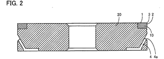
- FIG. 2 is a cross-sectional view taken along line II-II of FIG.
- a coolant flow path 4 is provided inside the cutting insert according to the embodiment.
- the coolant flow path 4 is connected to the flank 2. From another point of view, one end of the coolant flow path 4 forms a coolant jet port 4 a by opening at the flank 2.
- the coolant flows in the coolant flow path 4. It is preferable that the coolant flow path 4 be inclined such that the distance to the cutting edge 3 becomes smaller as it approaches the flank 2.
- the flank surface 2 is provided with a coolant guiding groove 5.
- the coolant guiding groove 5 is connected to the coolant flow path 4 at the flank surface 2. That is, the second end 5 b (base end portion) of the coolant guiding groove 5 is connected to the coolant jet port 4 a.
- the coolant guiding groove 5 extends from the coolant channel 4 toward the cutting edge 3. That is, the first end 5 a (tip portion) of the coolant guiding groove 5 is disposed at a position closer to the cutting edge 3 than the second end 5 b.
- the number of coolant guiding grooves 5 may be one or plural.
- FIG. 3 is a cross-sectional view taken along line III-III of FIG. III-III is a cross section parallel to the rake face 1.
- the flank 2 is recessed in the coolant guiding groove 5.
- the coolant guiding groove 5 has a cross-sectional area A.
- the cross sectional area A is a cross sectional area of the coolant guiding groove 5 in a cross section parallel to the rake face 1.
- the cross-sectional area A is an area of a portion surrounded by a wall surface of the coolant guiding groove 5 and a straight line connecting both ends of the coolant guiding groove 5 in a cross section parallel to the rake face 1.
- the cross-sectional area A of the coolant guiding groove 5 be smaller as it goes from the coolant flow path 4 side to the cutting edge 3 side (as it goes from the second end 5 b side to the first end 5 a side).
- the cross-sectional shape of the coolant guiding groove 5 in a cross section parallel to the rake face 1 is, for example, a curved shape.
- the cross-sectional shape of the coolant guiding groove 5 in a cross section parallel to the rake face 1 is not limited to this.
- the cross-sectional shape of the coolant guiding groove 5 in a cross section parallel to the rake face 1 may be, for example, a rectangular shape.
- the coolant guiding groove 5 has a depth D.
- the depth D is a distance between a straight line connecting both ends of the coolant guiding groove 5 and a bottom of the coolant guiding groove 5 in a cross section parallel to the rake face 1.
- the depth D is preferably 0.2 mm or more and 2.0 mm or less.
- the coolant guiding groove 5 has a first end 5a and a second end 5b.
- the first end 5 a is an end on the cutting edge 3 side.
- the second end 5 b is the opposite end of the first end 5 a. That is, the second end 5 b is an end on the coolant flow path 4 side.
- the first end 5 a is spaced from the cutting edge 3 by a distance L.
- the distance L is the distance between the cutting edge 3 and the first end 5 a in the direction orthogonal to the cutting edge 3.
- the distance L is 0.3 mm or more and 1.5 mm or less.
- the distance L is more preferably 0.3 mm or more and 1.0 mm or less.
- the coolant guiding groove 5 preferably extends such that the first end 5 a reaches the cutting edge tip 10.
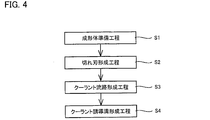
- FIG. 4 is process drawing which shows the manufacturing method of the cutting insert which concerns on embodiment.
- the method of manufacturing the cutting insert according to the embodiment includes a formed body preparing step S1, a cutting edge forming step S2, a coolant flow path forming step S3, and a coolant guiding groove forming step S4. ing.
- a formed body to be a cutting insert is prepared by passing through the cutting edge forming step S2, the coolant flow path forming step S3 and the coolant guiding groove forming step S4.
- the molded body has a first portion and a second portion.
- the first portion is a portion that becomes the cutting edge tip 10 through the cutting edge forming step S2, the coolant flow path forming step S3, and the coolant guiding groove forming step S4.
- the second part is a part to be the base 20 by passing through the cutting edge forming step S2, the coolant flow path forming step S3 and the coolant guiding groove forming step S4.
- the first part is prepared by sintering a powder such as CBN, PCD or the like.
- the second part is prepared by sintering a mixture of WC (tungsten carbide) and a binder such as Co (cobalt).
- the molded body is obtained by fixing the first portion and the second portion by brazing or the like.
- a rake face 1 and a flank face 2 are formed on the surface of the molded body prepared in the molded body preparing step S1.
- the cutting edge 3 is formed.
- the rake face 1, the flank face 2 and the cutting edge 3 are formed by polishing the surface of the molded body.
- the coolant flow passage 4 is formed inside the molded body prepared in the molded body preparation step S1.
- the coolant flow path 4 is formed, for example, by drilling the formed body.
- the coolant guiding groove 5 is formed on the molded body prepared in the molded body preparing step S1.
- the coolant guiding groove 5 is formed, for example, by irradiating a laser to the flank surface 2 (or the surface of the compact that becomes the flank surface 2 by performing the cutting edge forming step S2) to form a part of the compact It is done by removing.
- the execution order of cutting edge formation process S2, coolant channel formation process S3, and coolant guidance slot formation process S4 is arbitrary.
- coolant induction slot formation process S4 may be performed, and cutting blade formation process S2 may be performed further after that.
- the cutting edge forming step S2 may be performed after the coolant flow path forming step S3, and the coolant guiding groove forming step S4 may be performed thereafter.
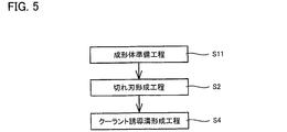
- FIG. 5 is process drawing which shows another example of the manufacturing method of the cutting insert which concerns on embodiment.
- the method of manufacturing the cutting insert according to the embodiment includes a formed body preparing step S11, a cutting edge forming step S2, and a coolant guiding groove forming step S4.
- the molded body preparation step S11 a molded body provided with the coolant flow path 4 inside is prepared. That is, when preparing the formed body, the coolant flow path 4 may be formed simultaneously (the step of preparing the formed body may include the step of forming the coolant flow path 4).
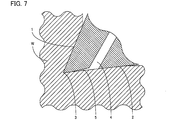
- FIG. 6 is a schematic view of cutting using the cutting insert according to the embodiment. As shown in FIG. 6, in the cutting using the cutting insert according to the embodiment, the workpiece W and the flank 2 are in close contact. Therefore, the coolant supplied from the outside of the cutting insert according to the embodiment hardly reaches the vicinity of the cutting edge 3.
- the coolant guiding groove 5 is provided on the flank surface 2. Since the flank 2 is recessed in the coolant guiding groove 5, a space is present between the workpiece W and the coolant guiding groove 5 even when the flank 2 and the workpiece W are in close contact with each other. As described above, the coolant guiding groove 5 is connected to the coolant flow path 4 at the flank surface 2. Further, as described above, the coolant guiding groove 5 extends from the coolant flow path 4 toward the cutting edge 3. Therefore, in the cutting insert according to the embodiment, the coolant flowing through the coolant flow path 4 is more reliably supplied in the vicinity of the cutting edge 3 through the space defined by the work material W and the coolant guiding groove 5 .
- the wall thickness of the cutting insert according to the embodiment is reduced, so the strength is reduced.
- the strength in the vicinity of the cutting edge greatly affects the durability of the cutting insert.
- the cross-sectional area A decreases as going from the coolant flow path 4 side to the cutting edge 3 side, strength reduction of the cutting insert on the side closer to the cutting edge 3 can be suppressed . Further, in this case, as the cross-sectional area A becomes smaller, the coolant is pushed out of the coolant guide groove 5 toward the cutting edge 3. Therefore, in this case, the coolant can be more reliably supplied to the vicinity of the cutting edge 3 while suppressing the reduction in strength of the cutting insert in the vicinity of the cutting edge.
- the coolant may not easily enter the coolant guiding groove 5 due to the surface tension of the coolant.
- the depth D is 0.2 mm or more and 2.0 mm or less, it is possible to suppress that the coolant is less likely to enter the coolant guiding groove 5 due to the influence of the surface tension of the coolant.
- the coolant flow path 4 when the coolant flow path 4 is provided to be inclined so that the distance from the flank 3 to the cutting edge 3 becomes short, the coolant flowing through the coolant flow path 4 at the time of cutting It is easy to flow between the workpiece W and the coolant guiding groove 5. Therefore, in this case, the coolant can be more reliably supplied near the cutting edge 3.
- Reference Signs List 1 rake face, 2 flank face, 3 cutting edge, 4 coolant flow path, 4a coolant outlet, 5 coolant guiding groove, 5a first end, 5b second end, 10 cutting edge tip, 20 base, 20a top face, 20b Back surface, 20c side surface, 20d attachment portion, A cross sectional area, D depth, L distance, S1 formed body preparing step, S11 formed body preparing step, S2 cutting edge forming step, S3 forming step, S4 coolant guiding groove forming step, W Work material.
Abstract
Priority Applications (5)
| Application Number | Priority Date | Filing Date | Title |
|---|---|---|---|
| US16/631,267 US11554427B2 (en) | 2017-07-19 | 2018-05-18 | Cutting insert and method for manufacturing cutting insert |
| KR1020207000575A KR20200016364A (ko) | 2017-07-19 | 2018-05-18 | 절삭 인서트 및 절삭 인서트의 제조 방법 |
| JP2019530902A JP7131750B2 (ja) | 2017-07-19 | 2018-05-18 | 切削インサート及び切削インサートの製造方法 |
| EP18834652.2A EP3656493A4 (fr) | 2017-07-19 | 2018-05-18 | Plaquette de coupe et procédé de fabrication de plaquette de coupe |
| CN201880047398.0A CN110891720A (zh) | 2017-07-19 | 2018-05-18 | 切削刀具和用于制造切削刀具的方法 |
Applications Claiming Priority (2)
| Application Number | Priority Date | Filing Date | Title |
|---|---|---|---|
| JP2017-140115 | 2017-07-19 | ||
| JP2017140115 | 2017-07-19 |
Publications (1)
| Publication Number | Publication Date |
|---|---|
| WO2019017064A1 true WO2019017064A1 (fr) | 2019-01-24 |
Family
ID=65015717
Family Applications (1)
| Application Number | Title | Priority Date | Filing Date |
|---|---|---|---|
| PCT/JP2018/019311 WO2019017064A1 (fr) | 2017-07-19 | 2018-05-18 | Plaquette de coupe et procédé de fabrication de plaquette de coupe |
Country Status (6)
| Country | Link |
|---|---|
| US (1) | US11554427B2 (fr) |
| EP (1) | EP3656493A4 (fr) |
| JP (1) | JP7131750B2 (fr) |
| KR (1) | KR20200016364A (fr) |
| CN (1) | CN110891720A (fr) |
| WO (1) | WO2019017064A1 (fr) |
Cited By (4)
| Publication number | Priority date | Publication date | Assignee | Title |
|---|---|---|---|---|
| US20190054545A1 (en) * | 2016-12-20 | 2019-02-21 | Sumitomo Electric Hardmetal Corp. | Cutting tool and manufacturing method thereof |
| US10654116B2 (en) * | 2017-10-25 | 2020-05-19 | Tungaloy Corporation | Cutting insert, metal spacer and holder |
| WO2021211415A1 (fr) * | 2020-04-16 | 2021-10-21 | Allied Machine & Engineering Corporation | Systèmes de forage munis d'agencements de distribution de fluide de refroidissement et procédés |
| JP7418960B2 (ja) | 2019-02-08 | 2024-01-22 | 国立大学法人東海国立大学機構 | 切削インサートおよび切削工具 |
Families Citing this family (4)
| Publication number | Priority date | Publication date | Assignee | Title |
|---|---|---|---|---|
| JP2018027605A (ja) * | 2016-08-19 | 2018-02-22 | 住友電工ハードメタル株式会社 | 切削工具用敷板および切削工具 |
| JP7001245B2 (ja) * | 2019-08-01 | 2022-01-19 | 住友電工ハードメタル株式会社 | 切削工具の製造方法 |
| EP4035808A1 (fr) * | 2021-02-01 | 2022-08-03 | KOMET Deutschland GmbH | Élément de coupe et outil d'usinage par enlèvement de copeaux |
| CZ309280B6 (cs) * | 2021-03-30 | 2022-07-13 | Západočeská Univerzita V Plzni | Soustružnický nástroj |
Citations (9)
| Publication number | Priority date | Publication date | Assignee | Title |
|---|---|---|---|---|
| JPH05237706A (ja) * | 1991-09-27 | 1993-09-17 | Iscar Ltd | 金属切削用工具 |
| JPH05301104A (ja) * | 1992-04-28 | 1993-11-16 | Sumitomo Electric Ind Ltd | スローアウェイチップおよびその製造方法ならびに切削工具 |
| JP2001198708A (ja) * | 2000-01-11 | 2001-07-24 | Fuji Mach Mfg Co Ltd | 切削工具および切削加工方法 |
| JP2008238342A (ja) * | 2007-03-27 | 2008-10-09 | Kyocera Corp | スローアウェイインサート、これを装着した転削工具および切削方法 |
| JP2010179412A (ja) * | 2009-02-05 | 2010-08-19 | Jtekt Corp | 切削用工具および切削加工方法 |
| JP2013049106A (ja) * | 2011-08-30 | 2013-03-14 | Sumitomo Electric Hardmetal Corp | 逃げ面内部給油孔付き超高圧焼結体工具 |
| US20160158855A1 (en) * | 2014-12-09 | 2016-06-09 | Kennametal Inc. | Cutting insert with internal coolant passages and method of making same |
| JP2016190275A (ja) | 2015-03-30 | 2016-11-10 | 国立大学法人 東京大学 | 切削インサート及び刃先交換式バイト |
| JP2017140115A (ja) | 2016-02-08 | 2017-08-17 | テルモ株式会社 | 脊椎治療方法および脊椎治療用カテーテル |
Family Cites Families (9)
| Publication number | Priority date | Publication date | Assignee | Title |
|---|---|---|---|---|
| DE504275C (de) * | 1926-12-14 | 1930-08-04 | Alexander Jgnatieff | Waermeableitungseinrichtung an Werkzeugen |
| US4535216A (en) | 1983-10-14 | 1985-08-13 | Rockwell International Corporation | Metal-working tool using electrical heating |
| US5775854A (en) | 1991-09-27 | 1998-07-07 | Iscar Ltd. | Metal cutting tool |
| JP2003266207A (ja) * | 2002-03-14 | 2003-09-24 | Ngk Spark Plug Co Ltd | バイト |
| JP4830377B2 (ja) * | 2005-07-11 | 2011-12-07 | コニカミノルタオプト株式会社 | 切削工具 |
| US20070225754A1 (en) | 2006-03-21 | 2007-09-27 | Ethicon Endo-Surgery, Inc. | Medical instrument having an engagement mechanism |
| JP5237706B2 (ja) | 2008-06-25 | 2013-07-17 | パナソニック株式会社 | 水栓装置 |
| WO2012047795A1 (fr) * | 2010-10-04 | 2012-04-12 | Michigan Technological University | Refroidissement par micro-jet d'outils de coupe |
| CN203751361U (zh) * | 2014-04-10 | 2014-08-06 | 哈尔滨汽轮机厂有限责任公司 | 利用冷风冷却的车削用车刀 |
-
2018
- 2018-05-18 CN CN201880047398.0A patent/CN110891720A/zh active Pending
- 2018-05-18 JP JP2019530902A patent/JP7131750B2/ja active Active
- 2018-05-18 WO PCT/JP2018/019311 patent/WO2019017064A1/fr unknown
- 2018-05-18 EP EP18834652.2A patent/EP3656493A4/fr active Pending
- 2018-05-18 KR KR1020207000575A patent/KR20200016364A/ko not_active Application Discontinuation
- 2018-05-18 US US16/631,267 patent/US11554427B2/en active Active
Patent Citations (9)
| Publication number | Priority date | Publication date | Assignee | Title |
|---|---|---|---|---|
| JPH05237706A (ja) * | 1991-09-27 | 1993-09-17 | Iscar Ltd | 金属切削用工具 |
| JPH05301104A (ja) * | 1992-04-28 | 1993-11-16 | Sumitomo Electric Ind Ltd | スローアウェイチップおよびその製造方法ならびに切削工具 |
| JP2001198708A (ja) * | 2000-01-11 | 2001-07-24 | Fuji Mach Mfg Co Ltd | 切削工具および切削加工方法 |
| JP2008238342A (ja) * | 2007-03-27 | 2008-10-09 | Kyocera Corp | スローアウェイインサート、これを装着した転削工具および切削方法 |
| JP2010179412A (ja) * | 2009-02-05 | 2010-08-19 | Jtekt Corp | 切削用工具および切削加工方法 |
| JP2013049106A (ja) * | 2011-08-30 | 2013-03-14 | Sumitomo Electric Hardmetal Corp | 逃げ面内部給油孔付き超高圧焼結体工具 |
| US20160158855A1 (en) * | 2014-12-09 | 2016-06-09 | Kennametal Inc. | Cutting insert with internal coolant passages and method of making same |
| JP2016190275A (ja) | 2015-03-30 | 2016-11-10 | 国立大学法人 東京大学 | 切削インサート及び刃先交換式バイト |
| JP2017140115A (ja) | 2016-02-08 | 2017-08-17 | テルモ株式会社 | 脊椎治療方法および脊椎治療用カテーテル |
Cited By (6)
| Publication number | Priority date | Publication date | Assignee | Title |
|---|---|---|---|---|
| US20190054545A1 (en) * | 2016-12-20 | 2019-02-21 | Sumitomo Electric Hardmetal Corp. | Cutting tool and manufacturing method thereof |
| US10632542B2 (en) * | 2016-12-20 | 2020-04-28 | Sumitomo Electric Hardmetal Corp. | Cutting tool and manufacturing method thereof |
| US10654116B2 (en) * | 2017-10-25 | 2020-05-19 | Tungaloy Corporation | Cutting insert, metal spacer and holder |
| JP7418960B2 (ja) | 2019-02-08 | 2024-01-22 | 国立大学法人東海国立大学機構 | 切削インサートおよび切削工具 |
| WO2021211415A1 (fr) * | 2020-04-16 | 2021-10-21 | Allied Machine & Engineering Corporation | Systèmes de forage munis d'agencements de distribution de fluide de refroidissement et procédés |
| US11590587B2 (en) | 2020-04-16 | 2023-02-28 | Allied Machine & Engineering Corporation | Drill systems with coolant delivery arrangements and methods |
Also Published As
| Publication number | Publication date |
|---|---|
| JPWO2019017064A1 (ja) | 2020-05-28 |
| EP3656493A4 (fr) | 2021-04-28 |
| US20200215618A1 (en) | 2020-07-09 |
| CN110891720A (zh) | 2020-03-17 |
| KR20200016364A (ko) | 2020-02-14 |
| JP7131750B2 (ja) | 2022-09-06 |
| US11554427B2 (en) | 2023-01-17 |
| EP3656493A1 (fr) | 2020-05-27 |
Similar Documents
| Publication | Publication Date | Title |
|---|---|---|
| WO2019017064A1 (fr) | Plaquette de coupe et procédé de fabrication de plaquette de coupe | |
| JP7091583B2 (ja) | 切削工具用ホルダ | |
| KR102307031B1 (ko) | 일체 형성된 냉각제 편향부를 갖는 냉각 챔버 및 공구 몸체를 갖는 절삭 공구 | |
| CN110177641B (zh) | 切削工具及切削加工物的制造方法 | |
| US20120087746A1 (en) | Cutting tools and cutting inserts including internal cooling | |
| JP2013107196A (ja) | クーラント供給を強化した切削アセンブリ | |
| CN109562458B (zh) | 切削工具用刀架及切削工具、以及使用它们的切削加工物的制造方法 | |
| CN110719822B (zh) | 切削刀具和铣削工具 | |
| JP2014018891A (ja) | 切削インサート | |
| WO2019163677A1 (fr) | Outil de coupe et procédé de fabrication d'une pièce à usiner coupée | |
| JPWO2017018369A1 (ja) | 切削工具及びこれを用いた切削加工物の製造方法 | |
| CN113316494A (zh) | 切削刀具 | |
| JP6011747B1 (ja) | 切削工具 | |
| JP6272457B2 (ja) | 切削インサート、切削工具及び切削加工物の製造方法 | |
| KR20110003461A (ko) | 건 드릴 | |
| JP2019018294A (ja) | 切削インサート | |
| WO2017110903A1 (fr) | Porte-outil de coupe, outil de coupe, et procédé pour fabriquer une pièce à travailler coupée | |
| WO2017043520A1 (fr) | Pièce rapportée de coupe, outil de coupe et procédé de fabrication de pièce à travailler coupée | |
| US10792738B2 (en) | Cutting tool and method of manufacturing machined product | |
| US11872641B2 (en) | Drill and method for manufacturing machined product | |
| JP7250257B1 (ja) | チップ及び切削工具 | |
| JP7344376B2 (ja) | 切削インサート、切削工具および切削加工物の製造方法 | |
| JP3120935U (ja) | ドリル | |
| JP6418765B2 (ja) | 切削インサート、切削工具および切削加工物の製造方法 | |
| CN116348226A (zh) | 刀架、切削刀具以及切削加工物的制造方法 |
Legal Events
| Date | Code | Title | Description |
|---|---|---|---|
| 121 | Ep: the epo has been informed by wipo that ep was designated in this application |
Ref document number: 18834652 Country of ref document: EP Kind code of ref document: A1 |
|
| ENP | Entry into the national phase |
Ref document number: 2019530902 Country of ref document: JP Kind code of ref document: A |
|
| ENP | Entry into the national phase |
Ref document number: 20207000575 Country of ref document: KR Kind code of ref document: A |
|
| NENP | Non-entry into the national phase |
Ref country code: DE |
|
| ENP | Entry into the national phase |
Ref document number: 2018834652 Country of ref document: EP Effective date: 20200219 |