WO2019017052A1 - センサ、測定装置及びセンサの製造方法 - Google Patents
センサ、測定装置及びセンサの製造方法 Download PDFInfo
- Publication number
- WO2019017052A1 WO2019017052A1 PCT/JP2018/018396 JP2018018396W WO2019017052A1 WO 2019017052 A1 WO2019017052 A1 WO 2019017052A1 JP 2018018396 W JP2018018396 W JP 2018018396W WO 2019017052 A1 WO2019017052 A1 WO 2019017052A1
- Authority
- WO
- WIPO (PCT)
- Prior art keywords
- sensor
- puncture needle
- present
- plate
- extension
- Prior art date
- Legal status (The legal status is an assumption and is not a legal conclusion. Google has not performed a legal analysis and makes no representation as to the accuracy of the status listed.)
- Ceased
Links
Images

















Classifications
-
- A—HUMAN NECESSITIES
- A61—MEDICAL OR VETERINARY SCIENCE; HYGIENE
- A61B—DIAGNOSIS; SURGERY; IDENTIFICATION
- A61B5/00—Measuring for diagnostic purposes; Identification of persons
- A61B5/145—Measuring characteristics of blood in vivo, e.g. gas concentration or pH-value ; Measuring characteristics of body fluids or tissues, e.g. interstitial fluid or cerebral tissue
- A61B5/1468—Measuring characteristics of blood in vivo, e.g. gas concentration or pH-value ; Measuring characteristics of body fluids or tissues, e.g. interstitial fluid or cerebral tissue using chemical or electrochemical methods, e.g. by polarographic means
- A61B5/1473—Measuring characteristics of blood in vivo, e.g. gas concentration or pH-value ; Measuring characteristics of body fluids or tissues, e.g. interstitial fluid or cerebral tissue using chemical or electrochemical methods, e.g. by polarographic means invasive, e.g. introduced into the body by a catheter
-
- A—HUMAN NECESSITIES
- A61—MEDICAL OR VETERINARY SCIENCE; HYGIENE
- A61B—DIAGNOSIS; SURGERY; IDENTIFICATION
- A61B5/00—Measuring for diagnostic purposes; Identification of persons
- A61B5/145—Measuring characteristics of blood in vivo, e.g. gas concentration or pH-value ; Measuring characteristics of body fluids or tissues, e.g. interstitial fluid or cerebral tissue
- A61B5/1468—Measuring characteristics of blood in vivo, e.g. gas concentration or pH-value ; Measuring characteristics of body fluids or tissues, e.g. interstitial fluid or cerebral tissue using chemical or electrochemical methods, e.g. by polarographic means
- A61B5/1486—Measuring characteristics of blood in vivo, e.g. gas concentration or pH-value ; Measuring characteristics of body fluids or tissues, e.g. interstitial fluid or cerebral tissue using chemical or electrochemical methods, e.g. by polarographic means using enzyme electrodes, e.g. with immobilised oxidase
Definitions
- the present disclosure relates to a sensor, a measurement device, and a method of manufacturing the sensor.
- a signal generating unit that generates a signal according to the amount of an analyte (for example, glucose) in body fluid of a living body It is known to have.
- a sensor may have a puncture needle portion having a longitudinal central axis and holding a signal generation portion as described in, for example, Patent Document 2.
- Such a puncture needle usually includes a puncture needle member having a central longitudinal axis.
- An object of the present disclosure is to provide an improved sensor, a measuring device and a method of manufacturing the sensor.
- the sensor as one aspect of the present invention is A signal generation unit that generates a signal according to the amount of analyte in body fluid of a living body;
- a puncture needle having a longitudinal central axis and holding the signal generator;
- the puncture needle portion is made of the same material, and has an extension portion continuously extending from the puncture needle portion and extending in a direction intersecting the central axis.
- the extension has one or more plate-like parts.
- the one or more plate-like parts extend along a predetermined plane,
- the angle between the central axis of the puncture needle portion and the predetermined plane is 30 ° to 90 °.
- outer peripheries of the one or more plate-like parts are respectively connected to the proximal end face of the puncture needle part.
- the puncture needle portion has a hollow portion in which the signal generation portion is disposed.
- the puncture needle portion and the extension portion are made of a metal material.
- the signal generation unit has two or more electrodes capable of generating an electrical signal as the signal.
- each of the two or more electrodes has a contact disposed in the extension.
- Each of the two or more electrodes is formed of a laminated electrode having a conductive layer laminated on a substrate and an insulating layer laminated on the conductive layer.
- the measuring device as an aspect of the present invention is A sensor as one aspect of the present invention; And a measuring device capable of measuring the amount of the analyte based on the signal by being operatively connected to the sensor.
- the measuring device comprises a base plate locatable along the surface of the living body, The extension of the sensor is connected to the base plate, The measuring device is attachable to the base plate.
- the base plate has a through hole into which the puncture needle portion of the sensor is inserted.
- a method of manufacturing a sensor as one aspect of the present invention is A method of manufacturing a sensor, comprising: a puncture needle holding a signal generation unit that generates a signal according to the amount of analyte in a body fluid of a living body; and an extension continuously extending from the puncture needle. Punching out a first portion for forming the puncture needle portion and a second portion connected to the first portion and for forming the extending portion from the metal plate by press processing; Bending the first portion relative to the second portion.
- the manufacturing method includes a rounding process of rolling the first portion into a tubular shape by pressing between the punching process and the bending process.
- an improved sensor, measurement device and method of manufacturing the sensor can be provided.
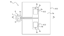
- FIG. 1A It is a figure which shows typically the sensor which concerns on 1st Embodiment of this invention, Comprising: It is sectional drawing in alignment with the AA of FIG. 1B. It is the top view which looked at the sensor shown to FIG. 1A from the proximal end side of the puncture needle part.
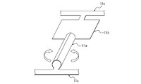
- FIG. 2 is a cross-sectional view taken along the line BB of FIG. 1A. It is a figure for demonstrating the manufacture point of the sensor shown to FIG. 1A, Comprising: The mode at the time of completion
- FIG. 4 is a top view of a base plate and a sensor in the measuring device shown in FIG. 3; It is a top view of a base plate and a sensor in a measuring device concerning a 2nd embodiment of the present invention. It is a top view of a base plate and a sensor in a measuring device concerning a 3rd embodiment of the present invention. It is a partial cross section side view showing typically the measuring device concerning a 4th embodiment of the present invention.
- FIG. 6C is a cross-sectional view taken along the line CC of FIG. 6B.
- finish of the punching process shown in FIG. 9 is shown.
- the mode at the end of the rounding process shown in FIG. 9 is shown.
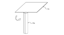
- the mode at the end of the bending process shown in FIG. 9 is shown.
- finish of the blade surface formation process shown in FIG. 9 is shown.
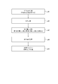
- separation process shown in FIG. 9 is shown. It is a flowchart which shows the order of the process implemented in the manufacturing method of the sensor which concerns on 3rd Embodiment of this invention.
- the mode at the end of the punching process shown in FIG. 11 is shown.
- the mode at the end of the rounding process shown in FIG. 11 is shown.
- separation process shown in FIG. 11 is shown.
- finish of the bending process shown in FIG. 11 is shown.
- finish of the blade surface formation process shown in FIG. 11 is shown.
- FIG. 13 It is a flowchart which shows the order of the process implemented in the manufacturing method of the sensor which concerns on 4th Embodiment of this invention.
- finish of the punching process shown in FIG. 13 is shown.
- the mode at the end of the rounding process shown in FIG. 13 is shown.
- separation process shown in FIG. 13 is shown.
- finish of the bending process shown in FIG. 13 is shown.
- a sensor 1A and a measuring device 2A according to a first embodiment of the present invention will be illustrated and described in detail.
- a sensor 1A according to the present embodiment includes a signal generation unit 3, a puncture needle unit 4, and an extension unit 5.
- the signal generation unit 3 generates a signal according to the amount of the analyte in the body fluid of the living body.
- the living body is a human body.
- the living body may be the body of an animal.
- the analyte in the body fluid is glucose contained in Interstitial fluid (ISF).
- ISF Interstitial fluid
- the analyte is not limited to glucose, and may be, for example, lactic acid.
- the body fluid is not limited to the interstitial fluid, and may be, for example, blood or urine.
- the signal generation unit 3 is a contact 3b operatively connected (connected) to a contact unit 3a (portion along the puncture needle 4) in contact with body fluid and a control unit 12a provided on the measuring instrument 12 (see FIG. 3). And. The signal generated by the contact portion 3a is transmitted to the control portion 12a that controls the measurement through the contact point 3b.
- the signal is an electrical signal (e.g. current).
- the signal may be, for example, an optical signal.
- the puncture needle 4 has a central axis O in the longitudinal direction of the puncture needle 4.
- the puncture needle unit 4 holds the signal generation unit 3.
- the extension portion 5 is made of the same material as the puncture needle portion 4 and extends continuously from the puncture needle portion 4 in a direction intersecting (in the present embodiment, orthogonal to) the central axis O.
- the extension portion 5 is made of the same material as the puncture needle portion 4 and is continuous with the central axis O continuously from the proximal end portion 4a of the puncture needle portion 4 (more specifically, the proximal end surface 4c). It extends in a crossing (orthogonal in this embodiment) direction.
- the extending portion 5 has one plate-like portion 6.
- the extension 5 may have two or more parts separated from each other.
- the extension part 5 may have two or more plate-like parts 6.
- the plate-like portion 6 has a rectangular flat plate shape in the present embodiment, but the shape and size thereof can be changed.
- the plate-like portion 6 may have an elliptical flat plate shape, or may have a curved plate shape.
- the extension 5 may not have a plate-like portion.
- the extending portion 5 may have one or more elongated portions.
- the plate-like portion 6 extends along a predetermined plane P.
- the magnitude of the angle ⁇ formed by the central axis O of the puncture needle 4 and the plane P is 90 °.
- the magnitude of the angle ⁇ may be 30 ° to 90 °, 45 ° to 90 °, or 60 ° to 90 °.
- the outer peripheral edge of the plate-like portion 6 is connected to the proximal end surface 4 c of the puncture needle portion 4.
- the extending portion 5 is configured to have two or more plate-like portions 6, the outer peripheral edges of the two or more plate-like portions 6 are respectively connected to the base end face 4 c of the puncture needle portion 4 It is also good.
- the puncture needle unit 4 has a hollow portion 7 in which the signal generation unit 3 is disposed. The entire circumference of the signal generation unit 3 is accommodated in the hollow portion 7. .
- the puncture needle portion 4 may not have the hollow portion 7, and in this case, a space corresponding to the hollow portion 7 may be filled with a polymer or a porous body that absorbs and permeates a body fluid.
- the puncture needle 4 may have a slit extending from the proximal end 4c to the distal end 4d. In this case, the signal generation unit 3 does not fly out of the puncture needle 4 from the slit opening surface. That is, the signal generation unit 3 is accommodated in the puncture needle unit 4.
- the signal generation unit 3 may be held by an adhesive or an engagement unit.
- the puncture needle portion 4 has a tip surface 4 d as a sharp needle tip capable of piercing the skin.
- the puncture needle portion 4 is not limited to a cylindrical shape, and may be a cylindrical shape other than a circular shape such as an elliptical cylindrical shape or a polygonal cylindrical shape.
- the puncture needle portion 4 may be formed with one or more openings penetrating in the radial direction. In this case, the tip 4b of the puncture needle 4 may be closed.
- the puncture needle 4 and the extension 5 are made of a metal material.
- the metallic material may be steel (eg stainless steel).
- the puncture needle 4 and the extension 5 may be made of materials other than metal (for example, hard synthetic resin).
- the signal generation unit 3 includes two electrodes 8 that generate an electric signal as the signal.
- the two electrodes 8 are configured as a pair of electrodes 8, one of which constitutes a working electrode and the other of which constitutes a counter electrode.
- a contact portion 3 a is provided at the tip of each electrode 8.
- a contact 3b is provided at the proximal end of each electrode 8.
- Each electrode 8 has a conductor 8a capable of transmitting the electrical signal generated at the contact portion 3a to the contact 3b.
- Each electrode 8 is electrically connected to the conductor 8a and has a detection reagent 8b (a glucose oxidase enzyme or a variant thereof, a glucose binding substance, etc.) that reacts with glucose.
- the detection reagent 8b is exposed on the surface of the contact portion 3a.
- the detection reagent 8b may be configured to react with components other than glucose, and to measure the amount of components other than glucose.
- the detection reagent 8b is applied or fixed to a part of the surface of the contact portion 3a.
- the detection reagent 8b is disposed on the conductor 8a by dipping, spray coating, fixation through covalent bonding, or the like.
- the detection reagent 8b is disposed only on a part (tip side) of a portion of the conductor 8a disposed along the puncture needle portion 4.
- Each electrode 8 has an insulator 8c covering a part of the conductor 8a.
- Each insulator 8c exposes the detection reagent 8b on the surface of the contact portion 3a.
- Each insulator 8c exposes the conductor 8a at the contact 3b. That is, each insulator 8c substantially completely covers the conductor 8a except for the portion where the detection reagent 8b is not disposed and the portion that constitutes the contact 3b.
- Each insulator 8c electrically insulates between the conductor 8a and the puncture needle 4 and the extension 5 made of a metal material.
- Each insulator 8c substantially completely covers the portion of the conductor 8a where the detection reagent 8b is not disposed at the contact portion 3a in contact with the body fluid. Each insulator 8c may cover a part of the detection reagent 8b.
- the insulator 8c is made of, for example, an insulating plastic material.
- the plastic material is selected, for example, from the group consisting of polyvinyl chloride, polycarbonate, polysulfone, nylon, polyurethane, polyester, acrylic resin, and polystyrene. Besides, non-conductive materials other than plastic such as cellulose may be used.
- the insulator 8c can be formed by various methods such as adhesion, welding, coating, printing, and semiconductor processes.
- the signal generation unit 3 may have three or more electrodes 8 capable of generating an electrical signal as the signal, and may use a reference electrode or a counter electrode.
- the signal generator 3 may be an optical signal generator that generates an optical signal as the signal.
- the optical signal generator may have a light guide (for example, an optical fiber) capable of transmitting the optical signal generated by the contact 3a to the contact 3b.
- the light signal generation unit may have a phosphor that forms the surface of the contact portion 3 a and generates fluorescence according to the amount and concentration of the analyte by excitation light from the light guide.
- the analyte may be glucose, lactic acid or other components.
- each of the two electrodes 8 has a contact 3 b disposed on the extension 5 (more specifically, on the upper surface 5 a of the extension 5).
- the upper surface means a surface viewed along the central axis O of the puncture needle portion 4 as viewed from the proximal end 4 a to the distal end 4 b.
- the lower surface means a surface opposite to the upper surface.
- the proximal ends of the two conductors 8 a may be disposed on the proximal end 4 a of the puncture needle 4 respectively.
- each of the two electrodes 8 has a conductive layer 9b stacked on the base, and a second insulating layer 9c as an insulating layer stacked on the conductive layer 9b.
- the base material includes the puncture needle portion 4 (more specifically, the puncture needle portion 4 and the extension portion 5). More specifically, the two electrodes 8 are respectively a first insulating layer 9a stacked adjacent to the base, a conductive layer 9b stacked adjacent to the first insulating layer 9a, and a conductive layer 9b And a second insulating layer 9c stacked adjacent to the first.
- the conductive layer 9b constitutes a conductor 8a.
- the insulator 8c is configured by the first insulating layer 9a and the second insulating layer 9c.
- a layer made of the detection reagent 8b may be partially stacked between the conductive layer 9b and the second insulating layer 9c.
- a protective layer made of a coating for reducing the adhesion of the measurement disturbing substance or the adhesion of the dirt to the electrode may be laminated (adjacent to) the second insulating layer 9c.
- a protective layer having an insulating property may be provided.
- the sensor 1A is manufactured from the metal plate 11 by press working as shown in FIGS. 2A to 2F.
- the sensor 1A may be manufactured in other ways.
- a developing body 11e is formed (punching process).
- the first portion 11a and the second portion 11b are connected to each other.
- the first portion 11 a is connected to the first frame portion 11 c of the metal plate 11.
- the second portion 11 b is connected to the second frame portion 11 d of the metal plate 11.
- the metal plate 11 may be punched out so that a plurality of expansion bodies 11e are connected via the first frame-shaped portion 11c and the second frame-shaped portion 11d.
- the first portion 11a is separated from the first frame portion 11c (first separation step).
- the first portion 11a is rolled and formed into a tubular shape (rolling process) by pressing.
- the butt end face of the first portion 11a may be welded.
- the first portion 11a is bent relative to the second portion 11b (folding step).
- the second portion 11b is separated from the second frame portion 11d (second separation step).
- a blade surface is formed by cutting or grinding the front-end
- the blade surface forming step may be performed between the bending step and the second separating step.
- the first portion 11 a forms the puncture needle portion 4 and the second portion 11 b forms the extension portion 5.
- the blade surface may be formed in the punching process and / or the first separating process.
- the puncture needle 4 may not have a blade surface.
- the puncture needle 4 is formed in a straight tubular shape.
- the puncture needle portion 4 may be formed in a tubular shape having a tapered portion (the outer diameter dimension gradually changes along the central axis O).
- the two electrodes 8 constituting the above-described laminated electrode may be provided on the metal plate 11 by, for example, a method such as adhesion, welding, coating, printing, or a semiconductor process.
- the measuring device 2A includes a sensor 1A and a measuring device 12.
- the measuring instrument 12 is operatively connected (connected) to (the extending portion 5 of) the sensor 1A (in this embodiment, electrically connected to the contact point 3b of the two electrodes 8 disposed in the extending portion 5)
- Control unit (processor) 12a that can measure the amount of the analyte (in this embodiment, the concentration of glucose in the interstitial fluid) based on the signal.
- the control unit 12a converts the measured concentration of glucose in the interstitial fluid into the concentration of glucose (blood sugar level) in blood.
- the measuring device 12 displays a display that displays the measured amount and / or concentration of the analyte, and further, the result (hereinafter collectively referred to as “measurement result”) obtained based on the amount (concentration). You may have.
- the measuring device 12 can transmit the measurement result to an external device.
- the measuring instrument 12 may have a storage device capable of storing measurement results and accessible from the outside.
- the measuring device 2A has a base plate 13 which can be disposed along the surface of a living body (for example, the surface of the skin, hereinafter also referred to as the living body surface).
- the lower surface of the base plate 13 may be provided with an attaching part that can be attached to the surface of the living body.
- the base plate 13 is formed of a synthetic resin material. The material forming the base plate 13 can be changed as appropriate.
- the extension 5 of the sensor 1A is connected to the base plate 13.
- the extension 5 may be fitted to or fixed to the base plate 13.
- the extension portion 5 may be fixed to the base plate 13 at the time of assembly, or may be fixed by insert molding.
- the measuring instrument 12 is attachable to the base plate 13. In the present embodiment, the measuring instrument 12 is detachably engaged with the base plate 13 as indicated by a two-dot chain arrow in FIG.
- the base plate 13 is formed with a through hole 13a into which the puncture needle portion 4 of the sensor 1A is inserted. Therefore, the extension 5 (plate-like portion 6) of the sensor 1A is connected to the upper surface 13b of the base plate 13.
- the measuring device 12 is electrically connected to the signal generation unit 3 of the sensor 1A (in the present embodiment, the contact 3b of the two electrodes 8 in the signal generation unit 3) (see FIG. 1A) by being attached to the base plate 13. And the amount of the analyte can be measured based on the signal.
- the extension 5 of the sensor 1A may be connected to the lower surface 13c of the base plate 13.
- the base plate 13 has an opening that enables a direct electrical connection between the signal generator 3 of the sensor 1A and the measuring instrument 12, or a conductive portion that allows an indirect electrical connection. May be provided.
- the outer peripheral surface of the proximal end 4 a of the puncture needle 4 is fixed to the inner peripheral surface of the base plate 13 in which the through hole 13 a is formed.
- the extension 5 is connected to the base plate 13 in a state where the outer peripheral surface of the proximal end 4a of the puncture needle 4 is separated from the base plate 13.
- the base plate 13 and the measuring device 12 have a rectangular shape in top view in this embodiment, but the shapes can be changed as appropriate.
- the base plate 13 and the measuring device 12 may have an oval shape or a circular shape in top view.
- the sensor 1A includes the puncture needle 4 holding the signal generator 3. Therefore, by puncturing the puncture needle part 4 on the surface of the living body, the sensor 1A can arrange the signal generation part 3 below the surface of the living body and contact the signal generation part 3 with the body fluid to generate the signal. Thus, the sensor 1A can be indwelled in a living body without using another puncture needle.
- the sensor 1A includes an extending portion 5 made of the same material as the puncture needle portion 4 and continuously extending from the puncture needle portion 4 in a direction intersecting the central axis O. Therefore, the sensor 1A can increase the area (connection area) of the connection portion between the sensor 1A and another object (in the present embodiment, the base plate 13) disposed on the living body surface by the extension portion 5.
- the outer peripheral surface of the puncture needle portion 4 is usually the other object (for example, Connect with the needle hub).
- the sensor 1A according to the present embodiment since the connection area can be secured by the extending portion 5 extending in the direction intersecting the central axis O, the protruding height of the entire measuring device 2A from the living body surface is It is possible to reduce the feeling of wearing. Further, the sensor 1A according to the present embodiment can be connected to another object via the extension portion 5 in a state where the outer peripheral surface of the proximal end portion 4a of the puncture needle portion 4 is separated from the other object. It is. That is, it is possible to connect to another object (for example, the base plate 13) through the extension portion 5 without providing a member (a needle hub, a fixture, etc.) for holding the puncture needle portion 4 on the outer peripheral surface of the puncture needle portion 4.
- another object for example, the base plate 13
- the proximal end of the puncture needle portion 4 even if a lateral force (force in a direction orthogonal to the axis O) is applied to the puncture needle portion 4. Since the outer peripheral surface of the portion 4a is separated from the other object, the occurrence of stress concentration at the base end 4a can be avoided.
- the puncture needle part 4 is stainless steel because it has a certain degree of elasticity and tensile strength. That is, it is possible to prevent breakage of the puncture needle at the connection portion between the puncture needle 4 and the needle hub, which are easily subjected to stress load. Therefore, the risk of causing breakage at the proximal end 4a can be reduced.
- the extending portion 5 has a plate-like portion 6. Therefore, the connection area between the extension 5 and the other object can be effectively increased.
- the outer peripheral edge of the plate-like portion 6 is connected to the proximal end surface 4 c of the puncture needle portion 4. Therefore, the puncture needle portion 4 and the extension portion 5 can be efficiently manufactured from the metal plate 11 by pressing.
- the puncture needle portion 4 has a hollow portion 7 in which the signal generation unit 3 is disposed.
- the signal generation unit 3 can be stably held by the puncture needle unit 4 without bringing the signal generation unit 3 having the detection reagent 8 b into contact with a living tissue.
- the puncture needle 4 and the extension 5 are made of a metal material. Therefore, due to the high hardness, stiffness and strength of the metal, it is possible to advantageously realize both the miniaturization of the sensor 1A and the reduction of the residual risk.
- the signal generation unit 3 includes two electrodes 8 capable of generating an electrical signal. Thus, electrochemical sensing techniques can measure the amount or concentration of analyte in body fluid.
- the two electrodes 8 each have a contact 3b disposed in the extension portion 5. Therefore, the electrical connection between the two electrodes 8 and (the control unit 12a of) the measuring instrument 12 can be facilitated.
- each of the two electrodes 8 is formed of a laminated electrode. Therefore, the two conductors 8 can be stably held by the puncture needle 4.
- the measuring device 2A has a base plate 13 in which a through hole 13a into which the puncture needle portion 4 of the sensor 1A is inserted is formed. Accordingly, when removing the measurement device 2A from the surface of the living body, the force in the removal direction can be applied to the extension portion 5 from the upper surface 13b of the base plate 13, so that the residual risk of the puncture needle portion 4 can be reduced. Further, as a procedure for removing the measuring device 2A from the surface of the living body, the base plate 13 may be removed from the surface of the living body after removing the measuring instrument 12 from the base plate 13.
- the extension part 5 has two plate-like-part 6 '.
- the two plate-like parts 6 ' extend along a (common) predetermined plane.
- the two plate-like portions 6 ' are respectively connected to the upper surface 13b of the base plate 13'.
- the contact points 3b (see FIG. 1B) of the two electrodes 8 may be arranged on only one of the two plate-like parts 6 '.
- One of the contacts 3b of the two electrodes 8 may be disposed in one of the two plate-like parts 6 ', and the other of the contacts 3b of the two electrodes 8 may be disposed in the other of the two plate-like parts 6'.
- the other configuration is the same as that of the sensor 1A and the measuring device 2A according to the first embodiment.
- the sensor 1 ⁇ / b> B can be manufactured from the metal plate 11 using press processing as in the case of the sensor 1 ⁇ / b> A according to the first embodiment. According to the configuration in which the extension 5 includes two (or three or more) plate-like parts 6 ′, the residual risk of the puncture needle 4 can be further reduced.
- the extension portion 5 may have two (or three or more) separated portions on which the contact points 3b of the electrodes 8 are respectively disposed.
- the portion is preferably plate-like. In this case, the height of protrusion from the surface of the living body can be suppressed.
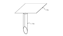
- the extending portion 5 has one plate-like portion 6 ′ ′.
- the central portion of the plate-like portion 6 ′ ′ is the base of the puncture needle portion 4. It is continued to the end face 4c.
- the puncture needle portion 4 can be obtained, for example, by deep-drawing the central portion of a rectangular metal plate and cutting or grinding the tip portion of the deep-drawn portion obliquely to form a blade surface.
- the signal generation unit 3 (two electrodes 8) may be disposed in the inside of the puncture needle unit 4 and in the plate-like portion 6 ′ ′.
- the extending portion 5 has one plate-like portion 14.
- the plate-like portion 14 has an uneven portion 14 a.
- the uneven portion 14 a is formed on the entire surface of the plate-like portion 14.
- the base plate 15 has a contact surface 15 a having a surface shape similar to that of the uneven portion 14 a of the plate-like portion 14 in a portion in contact with the plate-like portion 14.
- the uneven portion 14a is fixed to the contact surface 15a.
- the other configuration is the same as that of the sensor 1A and the measuring device 2A according to the first embodiment. According to the sensor 1D and the measuring device 2D according to the present embodiment, the connection area between the plate-like portion 14 and the base plate 15 can be effectively increased, and the residual risk of the puncture needle portion 4 can be further reduced.
- the signal generation unit 3 includes two linear electrodes 16.
- Each of the two electrodes 16 is composed of a laminated electrode having a conductive layer 16b laminated on a substrate and an insulating layer 16d laminated on the conductive layer 16b, and the substrate has a linear core. It consists of material 16a.
- the conductive layer 16 b is stacked adjacent to the substrate.
- the insulating layer 16d is stacked adjacent to the conductive layer 16b.
- the two electrodes 16 respectively form a linear core 16a, a conductive layer 16b substantially completely covering the core 16a, and the surface of the contact portion 3a, and the conductive layer 16b and It is electrically connected and has a detection reagent 16c that reacts with glucose, and an insulating layer 16d that covers a part of the conductive layer 16b.
- a protective layer having a coating function to reduce the adhesion of the measurement interfering substance or the adhesion of the soil to the electrode may be further laminated on the insulating layer 16d and the detection reagent 16c.
- the sensor 1E may be configured to react the detection reagent 16c with a component other than glucose and measure the amount of the component other than glucose.
- the detection reagent 16c is disposed only on a portion (tip side portion) of the portion disposed along the puncture needle portion 4 in the conductive layer 16b.
- Each insulating layer 16 d exposes the detection reagent 16 c on the surface of the contact portion 3 a.
- Each insulating layer 16 d exposes the conductive layer 16 b at the base end. That is, each insulating layer 16 d substantially completely covers the conductive layer 16 b except for the portion where the detection reagent 16 c is not disposed and the proximal end.
- Each insulating layer 16 d electrically insulates between the conductive layer 16 b and the puncture needle 4 and the extension 5 made of a metal material.
- Each insulating layer 16d substantially completely covers the portion of the conductive layer 16b where the detection reagent 16c is not disposed, at the contact portion 3a in contact with the body fluid. Each insulating layer 16 d may cover a part of the detection reagent 16 c.
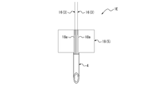
- the extending portion 5 has one plate-like portion 18. The plate-like portion 18 is formed with two grooves 18 a communicating with the inside of the puncture needle portion 4. In each groove 18a of the extension portion 5, a terminal member (not shown) forming the contact 3b is disposed. Each terminal member is electrically insulated with respect to extension 5. The base end of the conductive layer 16 b is electrically connected to each terminal member by soldering or the like.
- the sensor 1 ⁇ / b> E can be manufactured from the metal plate 11 using press processing as in the case of the sensor 1 ⁇ / b> A according to the first embodiment.
- the two electrodes 16 can be easily inserted into the puncture needle 4 using the two grooves 18a before the bending step.
- One of the two electrodes 16 can be guided by one of the two grooves 18a.
- the other of the two electrodes 16 may be guided by the other of the two grooves 18a.
- each electrode 16 may be fixed to the puncture needle 4 and / or the extension 5.
- each electrode 16 is connected to the terminal member, and as shown in FIG. 6C, the sensor 1E is obtained.
- the electrode 8 can be easily disposed inside the puncture needle 4.
- the extension 5 has one plate-like portion 19.
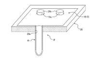
- the plate-like portion 19 has a hole 19a.
- the plate-like portion 19 is provided with two circular holes 19 a.
- the number of holes 19a provided in the plate-like portion 19 may be one, but it is preferable to provide two or more.
- the shape of the holes 19a provided in the plate-like portion 19 may be elliptical or polygonal, but is preferably circular.
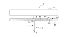
- a through hole 20a into which the puncture needle portion 4 of the sensor 1F is inserted is formed. Further, on the base plate 20, a convex portion 20c inserted into the hole 19a is formed. In the present embodiment, two cylindrical convex portions 20 c are formed on the base plate 20. However, the shape and the number of the convex portions 20c can be appropriately changed in accordance with the shape and the number of the hole portions 19a.
- the plate-like portion 19 of the sensor 1 F is connected to the upper surface 20 b of the base plate 20.
- the plate-like portion 19 may be fitted to or fixed to the base plate 20.
- the extension 19 may be fixed to the base plate 20 at the time of assembly, or may be fixed by insert molding.
- the other configuration is the same as that of the sensor 1A and the measuring device 2A according to the first embodiment.
- the coupling force between the plate-like portion 19 and the base plate 20 is enhanced by the engagement between the hole 19a and the convex 20c, and the residual risk of the puncture needle 4 is reduced. It can be further reduced.
- the hole 19 a is provided in the plate-like portion 19.
- a hollow convex portion (a convex portion formed of a peripheral wall and a closed wall that closes an axial end of the peripheral wall) may be provided.
- the base plate 20 may be provided with a projection or a recess that engages with the hollow projection.
- a conductive rubber which is a contact point between an electrode provided on the sensor 1F and the measuring instrument 12F is disposed inside the hollow convex portion.
- a method of manufacturing a sensor according to the first embodiment of the present invention will be exemplified in detail.
- the method of manufacturing the sensor according to the present embodiment will be described by way of example of manufacturing the sensor according to the first embodiment described above, but for example, sensors with other configurations such as the sensors according to the second to sixth embodiments. It is applicable also when manufacturing.
- a puncture needle 4 holding a signal generation unit 3 that generates a signal corresponding to the amount of analyte in body fluid of a living body and a continuous extension from the puncture needle 4 It is a manufacturing method of sensor 1A which has local part 5.
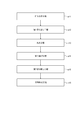
- the metal plate 11 is connected to the first portion 11 a for forming the puncture needle portion 4 and the first portion 11 a by press working, and the extension portion 5 is formed. And punching step p11 (see FIG. 2A), and bending step p14 (see FIG. 2D) for bending the first portion 11a with respect to the second portion 11b. Further, in the method of manufacturing a sensor according to the present embodiment, a rounding process p13 (see FIG. 2C) is formed between the punching process p11 and the bending process p14 by rolling the first portion 11a into a tubular shape by press processing. It contains. More specifically, in the present embodiment, as shown in FIG.
- the punching step p11 is performed, then the first separation step p12 is performed, then the rounding step p13 is performed, and then the bending step is performed.
- the process p14 is performed, then the second separation process p15 is performed, and then the blade surface forming process p16 is performed.
- the punching method is not limited to the mechanical punching method, and may be punching using a laser or the like.
- the metal plate 11 is punched out by press work, and developed with a first portion 11a forming the puncture needle portion 4 and a second portion 11b forming the extending portion 5 Body 11e is formed.
- the first portion 11a is connected to the first frame portion 11c of the metal plate 11, and the second portion 11b is connected to the second frame portion 11d of the metal plate 11. It is connected.
- the hole 19a or the hollow convex portion described in regard to the sensor 1F according to the sixth embodiment may be formed in the second portion 11b.
- the hole 19a or the hollow convex portion may be formed by a pressing process separately provided before and after the punching process p11.
- the first portion 11a is separated from the first frame portion 11c.
- the method of separation is not limited to the method of mechanical cutting, and a laser or the like may be used.
- the first portion 11a is rolled and formed into a tubular shape by pressing. At this time, the butt end face of the first portion 11a may be welded.
- Various types of welding can be used for welding. For example, welding such as carbon dioxide gas laser welding, YAG laser welding, or excimer laser welding is preferable.
- the first portion 11a is bent relative to the second portion 11b.
- the second portion 11b is separated from the second frame portion 11d.
- the blade surface is formed by obliquely cutting or grinding the tip end portion of the first portion 11a.
- the blade surface forming step p16 may be performed between the bending step p14 and the second separation step p15.
- Examples of the blade surface forming method include wire cutting, grinding, cutting, and electric discharge machining.
- the blade surface forming step may include a cleaning step, and electrolytic polishing or chemical polishing may be performed.
- the sensor 1A can be manufactured by press processing.
- the puncture needle 4 is formed in a straight tubular shape.
- the puncture needle portion 4 may be formed in a tubular shape having a tapered portion (the outer diameter dimension gradually changes along the central axis O).
- the two electrodes 8 constituting the above-described laminated electrode may be provided on the metal plate 11 by, for example, a method such as adhesion, welding, coating, printing, or semiconductor process.
- the groove 18a may be formed by pressing in the punching step p11.
- the grooves 18a may be formed by processing steps separately provided before and after the punching step p11.
- the sensor manufacturing method according to the present embodiment differs from the sensor manufacturing method according to the first embodiment in that it includes a blade surface forming step p24 that combines the blade surface forming step p16 and the first separation step p12. But otherwise it is similar.
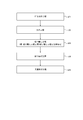
- the punching step p21 (see FIG. 10A) is performed first, then the rounding step p22 (see FIG. 10B) is performed, and then the bending step p23 (see FIG. 10C) Then, the blade surface forming step p24 (see FIG. 10D) is performed, and then the second separating step p25 is performed (see FIG. 10E).
- the manufacturing process can be simplified as compared with the method of manufacturing the sensor according to the first embodiment by the blade surface forming process p24 which also serves as the first separation process p12.
- the method of manufacturing the sensor according to the present embodiment is different from the method of manufacturing the sensor according to the first embodiment in that it includes the separation step p33 which combines the first separation step p12 and the second separation step p15. , Otherwise similar.
- the punching step p31 (see FIG. 12A) is performed first, then the rounding step p32 (see FIG. 12B) is performed, and then the separating step p33 (see FIG. 12C) Then, the bending step p34 (see FIG. 12D) is performed, and then the blade surface forming step p35 (see FIG. 12E) is performed.
- the order of the bending step p34 and the blade surface forming step p35 may be reversed.
- the manufacturing process can be simplified as compared with the method for manufacturing the sensor according to the first embodiment, by the separation process p33 which combines the first separation process p12 and the second separation process p15.
- the method of manufacturing the sensor according to this embodiment is different from the method of manufacturing the sensor according to the third embodiment in that it includes the punching step p41 which also serves as the blade surface forming step p35. is there.
- the punching process p41 a blade surface (or a surface similar to a blade surface) is formed on the first portion 11a by press forming the developed body 11e having the first portion 11a and the second portion 11b. An outline of the expanded shape is formed.
- the punching step p41 (see FIG. 14A) is performed first, then the rounding step p42 (see FIG. 14B) is performed, and then the separating step p43 (see FIG. 14C) Then, a bending step p44 (see FIG. 14D) is performed, and then a blade surface finishing step p45 is performed as needed.
- the manufacturing process can be simplified as compared with the method of manufacturing the sensor according to the third embodiment by the punching process p41 which also serves as the blade surface forming process p35.
Landscapes
- Life Sciences & Earth Sciences (AREA)
- Health & Medical Sciences (AREA)
- Physics & Mathematics (AREA)
- Biomedical Technology (AREA)
- Medical Informatics (AREA)
- General Chemical & Material Sciences (AREA)
- Chemical Kinetics & Catalysis (AREA)
- Biophysics (AREA)
- Pathology (AREA)
- Engineering & Computer Science (AREA)
- Chemical & Material Sciences (AREA)
- Heart & Thoracic Surgery (AREA)
- Optics & Photonics (AREA)
- Molecular Biology (AREA)
- Surgery (AREA)
- Animal Behavior & Ethology (AREA)
- General Health & Medical Sciences (AREA)
- Public Health (AREA)
- Veterinary Medicine (AREA)
- Measurement Of The Respiration, Hearing Ability, Form, And Blood Characteristics Of Living Organisms (AREA)
Abstract
センサは、生体の体液におけるアナライトの量に応じた信号を生成する信号生成部と、長手方向の中心軸線を有するとともに前記信号生成部を保持した穿刺針部と、前記穿刺針部と同一の材料からなるとともに前記穿刺針部から連続して前記中心軸線と交差する方向に延在する延在部とを有する。
Description
本開示は、センサ、測定装置及びセンサの製造方法に関する。
例えば血糖値の測定等の目的で用いられるセンサとして、例えば特許文献1及び2に記載されるように、生体の体液におけるアナライト(例えばグルコース)の量に応じた信号を生成する信号生成部を有するものが知られている。このようなセンサは、例えば特許文献2に記載されるように、長手方向の中心軸線を有するとともに信号生成部を保持した穿刺針部を有することもある。このような穿刺針部は、通常、長手方向の中心軸線を有する穿刺針部材を含んでいる。
特許文献1及び2に記載されるようなセンサ、及びそのようなセンサを有する測定装置には、改善の余地がある。
本開示の目的は、改善されたセンサ、測定装置及びセンサの製造方法を提供することにある。
本発明の一態様としてのセンサは、
生体の体液におけるアナライトの量に応じた信号を生成する信号生成部と、
長手方向の中心軸線を有するとともに前記信号生成部を保持した穿刺針部と、
前記穿刺針部と同一の材料からなるとともに前記穿刺針部から連続して前記中心軸線と交差する方向に延在する延在部とを有する。
生体の体液におけるアナライトの量に応じた信号を生成する信号生成部と、
長手方向の中心軸線を有するとともに前記信号生成部を保持した穿刺針部と、
前記穿刺針部と同一の材料からなるとともに前記穿刺針部から連続して前記中心軸線と交差する方向に延在する延在部とを有する。
本発明の1つの実施形態として、前記延在部は、1つ以上の板状部を有する。
本発明の1つの実施形態として、
前記1つ以上の板状部は、所定の平面に沿って延在しており、
前記穿刺針部の前記中心軸線と前記所定の平面とがなす角の大きさは、30°乃至90°である。
前記1つ以上の板状部は、所定の平面に沿って延在しており、
前記穿刺針部の前記中心軸線と前記所定の平面とがなす角の大きさは、30°乃至90°である。
本発明の1つの実施形態として、前記1つ以上の板状部の外周縁は、それぞれ、前記穿刺針部の前記基端面に連なっている。
本発明の1つの実施形態として、前記穿刺針部は、前記信号生成部が内部に配置された中空部を有する。
本発明の1つの実施形態として、前記穿刺針部及び前記延在部は、金属材料からなる。
本発明の1つの実施形態として、前記信号生成部は、前記信号としての電気信号を生成可能な2つ以上の電極を有する。
本発明の1つの実施形態として、前記2つ以上の電極は、それぞれ、前記延在部に配置された接点を有する。
本発明の1つの実施形態として、
前記2つ以上の電極は、それぞれ、基材に積層された導電層と、前記導電層に積層された絶縁層とを有する積層状電極で構成されている。
前記2つ以上の電極は、それぞれ、基材に積層された導電層と、前記導電層に積層された絶縁層とを有する積層状電極で構成されている。
本発明の一態様としての測定装置は、
本発明の一態様としてのセンサと、
前記センサに動作可能に接続することで前記信号に基づいて前記アナライトの量を測定可能な測定器とを有する。
本発明の一態様としてのセンサと、
前記センサに動作可能に接続することで前記信号に基づいて前記アナライトの量を測定可能な測定器とを有する。
本発明の1つの実施形態として、
前記測定装置は、前記生体の表面に沿って配置可能なベースプレートを有し、
前記センサの前記延在部は、前記ベースプレートに連結しており、
前記測定器は、前記ベースプレートに装着可能である。
前記測定装置は、前記生体の表面に沿って配置可能なベースプレートを有し、
前記センサの前記延在部は、前記ベースプレートに連結しており、
前記測定器は、前記ベースプレートに装着可能である。
本発明の1つの実施形態として、前記ベースプレートには、前記センサの前記穿刺針部が挿入される貫通孔を有する。
本発明の一態様としてのセンサの製造方法は、
生体の体液におけるアナライトの量に応じた信号を生成する信号生成部を保持した穿刺針部と前記穿刺針部から連続して延在する延在部とを有するセンサの製造方法であって、
プレス加工によって、金属板から、前記穿刺針部を形成するための第1部分と、前記第1部分に連結するとともに前記延在部を形成するための第2部分とを打ち抜く、打ち抜き工程と、
前記第1部分を前記第2部分に対して折り曲げる、折り曲げ工程と
を含む。
生体の体液におけるアナライトの量に応じた信号を生成する信号生成部を保持した穿刺針部と前記穿刺針部から連続して延在する延在部とを有するセンサの製造方法であって、
プレス加工によって、金属板から、前記穿刺針部を形成するための第1部分と、前記第1部分に連結するとともに前記延在部を形成するための第2部分とを打ち抜く、打ち抜き工程と、
前記第1部分を前記第2部分に対して折り曲げる、折り曲げ工程と
を含む。
本発明の1つの実施形態として、前記製造方法は、前記打ち抜き工程と前記折り曲げ工程との間に、プレス加工によって、前記第1部分を丸めて管状に成形する、丸め工程を含む。
本開示によれば、改善されたセンサ、測定装置及びセンサの製造方法を提供できる。
以下、図面を参照して、本発明の様々な実施形態に係るセンサ、測定装置及びセンサの製造方法について詳細に例示説明する。
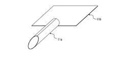
まず、図1A乃至図4Aを参照して、本発明の第1実施形態に係るセンサ1A及び測定装置2Aについて詳細に例示説明する。図1A及び図1Bに示すように、本実施形態に係るセンサ1Aは、信号生成部3と、穿刺針部4と、延在部5とを有している。信号生成部3は、生体の体液中のアナライトの量に応じた信号を生成する。本実施形態では、生体は、人体である。しかし、生体は、動物の体であってもよい。本実施形態では、体液中のアナライトは、間質液(ISF:Interstitial fluid)に含まれるグルコースである。しかし、アナライトは、グルコースに限られず、例えば乳酸等であってもよい。体液は、間質液に限られず、例えば血液や尿等であってもよい。信号生成部3は、体液と接触する接触部3a(穿刺針部4に沿う部分)と、測定器12(図3参照)に設けられた制御部12aと動作可能に接続(連結)する接点3bとを有している。接触部3aで生成された信号は、接点3bを通じて、測定を制御する制御部12aに伝達される。本実施形態では、信号は、電気信号(例えば電流)である。しかし、信号は、例えば光信号であってもよい。穿刺針部4は、穿刺針部4の長手方向の中心軸線Oを有している。穿刺針部4は、信号生成部3を保持している。延在部5は、穿刺針部4と同一の材料からなるとともに穿刺針部4から連続して中心軸線Oと交差(本実施形態では、直交)する方向に延在している。本実施形態では、延在部5は、穿刺針部4と同一の材料からなるとともに穿刺針部4の基端部4a(より具体的には、基端面4c)から連続して中心軸線Oと交差(本実施形態では、直交)する方向に延在している。
本実施形態では、延在部5は、1つの板状部6を有している。延在部5は、互いに分離した2つ以上の部分を有していてもよい。延在部5は、2つ以上の板状部6を有していてもよい。板状部6は、本実施形態では矩形平板状をなしているが、その形状及び大きさは変更が可能である。板状部6は、楕円形平板状をなしていてもよいし、湾曲板状をなしていてもよい。延在部5は、板状をなす部分を有していなくてもよい。延在部5は、1つ以上の長尺状部を有していてもよい。
本実施形態では、板状部6は、所定の平面Pに沿って延在している。本実施形態では、穿刺針部4の中心軸線Oと平面Pとがなす角θの大きさは、90°である。角θの大きさは、30°乃至90°、45°乃至90°、又は60°乃至90°であってもよい。
本実施形態では、図1Bに示すように、板状部6の外周縁は、穿刺針部4の基端面4cに連なっている。延在部5が2つ以上の板状部6を有するように構成した場合には、2つ以上の板状部6の外周縁は、それぞれ、穿刺針部4の基端面4cに連なっていてもよい。
本実施形態では、図1A及び図1Bに示すように、穿刺針部4は、信号生成部3が内部に配置された中空部7を有している。信号生成部3は、その全周が中空部7内に収容されている。。穿刺針部4は、中空部7を有していなくてもよく、この場合、中空部7に相当する空間に体液を吸収、透過するポリマーや多孔質体が充填されていてもよい。穿刺針部4は、その基端面4cから先端面4dまで延在するスリットを有していてもよい。この場合、信号生成部3がスリット開口面から穿刺針部4の外へ飛び出さない。すなわち、信号生成部3は穿刺針部4内に収容されている。このとき、信号生成部3は、接着剤や係合部によって保持されてもよい。本実施形態では、穿刺針部4は、皮膚に穿刺可能な鋭利な針先としての先端面4dを有する。穿刺針部4は、円筒状に限らず、楕円筒状又は多角形筒状などのような円形以外の筒状でもよい。穿刺針部4には、径方向に貫通する1つ以上の開口が形成されていてもよい。この場合、穿刺針部4の先端部4bは、閉塞されていてもよい。
本実施形態では、穿刺針部4及び延在部5は、金属材料からなっている。金属材料は、鋼鉄(例えばステンレス鋼)であってよい。穿刺針部4及び延在部5は、金属以外の材料(例えば硬質の合成樹脂など)からなっていてもよい。
図1A乃至図1Cに示すように、本実施形態では、信号生成部3は、前記信号としての電気信号を生成する2つの電極8からなっている。本実施形態では、2つの電極8は、一対の電極8として構成されており、その一方で作用極を構成し、他方で対極を構成している。各電極8の先端部には、接触部3aが設けられている。各電極8の基端部には、接点3bが設けられている。各電極8は、接触部3aで生成された電気信号を接点3bまで伝達可能な導電体8aを有している。各電極8は、導電体8aと電気的に接続し、グルコースと反応する検出試薬8b(グルコースオキシターゼ酵素若しくはその変異体又はグルコース結合性物質等)を有している。検出試薬8bは接触部3aの表面に露出している。検出試薬8bをグルコース以外の成分と反応するものとし、グルコース以外の成分の量を測定するように構成してもよい。本実施形態では、各電極8において、検出試薬8bは、接触部3aの表面の一部に塗布又は固定される。検出試薬8bは、導電体8a上に、ディッピング、スプレーコート、共有結合を介した固定等によって配置されている。より具体的には、検出試薬8bは、導電体8aにおける穿刺針部4に沿って配置された部分の一部(先端側部分)のみに配置されている。各電極8は、導電体8aの一部を覆う絶縁体8cを有している。各絶縁体8cは、検出試薬8bを接触部3aの表面に露出させている。各絶縁体8cは、接点3bにおいて導電体8aを露出させている。すなわち、各絶縁体8cは、導電体8aにおける、検出試薬8bが配置されていない部分と接点3bを構成する部分とを除いた部分を、実質的に完全に覆っている。各絶縁体8cは、導電体8aと、金属材料からなる穿刺針部4及び延在部5との間を電気的に絶縁している。各絶縁体8cは、体液と接触する接触部3aにおいて、導電体8aにおける検出試薬8bが配置されていない部分を、実質的に完全に覆っている。各絶縁体8cは、検出試薬8bの一部を覆っていてもよい。絶縁体8cは、例えば絶縁性のプラスチック材料によって構成される。このプラスチック材料としては、例えばポリ塩化ビニル、ポリカーボネート、ポリスルホン、ナイロン、ポリウレタン、ポリエステル、アクリル樹脂、及びポリスチレン等から成るグループから選択される。他にも、セルロースのようなプラスチック以外の非導電性材料を用いてもよい。絶縁体8cは、接着、溶着、塗布、印刷、半導体プロセス等の様々な方法によって形成することができる。信号生成部3は、前記信号としての電気信号を生成可能な3つ以上の電極8を有していてもよく、参照極や対極を用いてもよい。
信号生成部3は、前記信号としての光信号を生成する光信号生成部でもよい。光信号生成部は、接触部3aで生成された光信号を接点3bまで伝達可能な導光体(例えば、光ファイバ)を有していてもよい。光信号生成部は、接触部3aの表面を形成するとともに導光体からの励起光によって前記アナライトの量や濃度に応じた蛍光を発生する蛍光体を有していてもよい。このように光信号を用いる場合も、前記アナライトは、グルコース、乳酸又はそれら以外の成分であってもよい。
本実施形態では、2つの電極8は、それぞれ、延在部5(より具体的には、延在部5の上面5a)に配置された接点3bを有している。本明細書において、上面とは、穿刺針部4の中心軸線Oに沿って基端部4aの側から先端部4bの側に向かって視たときに見える面を意味する。下面とは、上面の反対側に位置する面を意味する。2つの導電体8aの基端部は、それぞれ、穿刺針部4の基端部4a上に配置されていてもよい。
本実施形態では、図1Aに示すように、2つの電極8は、それぞれ、基材に積層された導電層9bと、導電層9bに積層された絶縁層としての第2絶縁層9cとを有する積層状電極で構成されており、前記基材は、穿刺針部4を含んでいる(より具体的には、穿刺針部4及び延在部5からなっている)。より具体的には、2つの電極8は、それぞれ、基材に隣接して積層された第1絶縁層9aと、第1絶縁層9aに隣接して積層された導電層9bと、導電層9bに隣接して積層された第2絶縁層9cとを有している。各電極8において、導電層9bで導電体8aが構成されている。各電極8において、第1絶縁層9aと第2絶縁層9cとで絶縁体8cが構成されている。各電極8において、導電層9bと第2絶縁層9cとの間には検出試薬8bからなる層が部分的に積層されていてもよい。測定方法に応じて、測定妨害物質の付着、又は電極への汚れの付着を低減するためのコーティングからなる保護層を、第2絶縁層9cに(隣接して)積層してもよい。第2絶縁層9cの代わりに、絶縁性を有する保護層を設けてもよい。
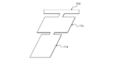
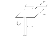
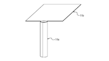
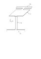
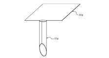
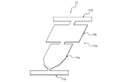
本実施形態では、センサ1Aは、図2A乃至図2Fに示す要領で、金属板11からプレス加工によって製造されている。センサ1Aは、他の要領で製造されてもよい。本実施形態では、まず、図2Aに示すように、金属板11がプレス加工によって打ち抜かれ、穿刺針部4を形成する第1部分11aと、延在部5を形成する第2部分11bとを有する展開体11eが形成される(打ち抜き工程)。第1部分11aと第2部分11bとは、互いに連結している。第1部分11aは、金属板11の第1枠状部11cに連結している。第2部分11bは、金属板11の第2枠状部11dに連結している。このとき、第1枠状部11cと第2枠状部11dとを介して、展開体11eが複数繋がった形状となるように、金属板11を打ち抜いてもよい。次に、図2Bに示すように、第1部分11aが、第1枠状部11cから切り離される(第1切り離し工程)。次に、図2Cに示すように、プレス加工によって第1部分11aが丸められ、管状に成形される(丸め工程)。このとき、第1部分11aの突き合わせ端面が溶接されてもよい。次に、図2Dに示すように、第1部分11aが第2部分11bに対して折り曲げられる(折り曲げ工程)。次に、図2Eに示すように、第2部分11bが、第2枠状部11dから切り離される(第2切り離し工程)。次に、図2Fに示すように、第1部分11aの先端部を斜めに切断又は研削することで、刃面が形成される(刃面形成工程)。刃面形成工程は折り曲げ工程と第2切り離し工程との間で実施されてもよい。これらの工程を経ることで、第1部分11aは穿刺針部4を形成し、第2部分11bは延在部5を形成する。刃面は、打ち抜き工程及び/又は第1切り離し工程で形成されてもよい。穿刺針部4は、刃面を有していなくてもよい。本実施形態では、穿刺針部4は、ストレートな管状をなすように形成されている。しかし、穿刺針部4は、テーパ部を有する(中心軸線Oに沿って外径寸法が漸次変化する)管状をなすように形成されてもよい。打ち抜き工程より前に、金属板11に、例えば接着、溶着、塗布、印刷、半導体プロセス等の手法によって、前述した積層状電極を構成する2つの電極8が設けられてもよい。
図3に示すように、本実施形態に係る測定装置2Aは、センサ1Aと、測定器12とを有している。測定器12は、センサ1A(の延在部5)に動作可能に接続(連結)する(本実施形態では、延在部5に配置された2つの電極8の接点3bに電気的に接続する)ことで前記信号に基づいて前記アナライトの量(本実施形態では、間質液におけるグルコースの濃度)を測定可能な制御部(プロセッサ)12aを有している。本実施形態では、制御部12aは、測定した間質液におけるグルコースの濃度を、血液におけるグルコースの濃度(血糖値)に換算する。測定器12は、測定した前記アナライトの量及び/又は濃度、さらには、当該量(濃度)に基づいて求めた結果(以下、これらを総称して「測定結果」という)を表示するディスプレイを有していてもよい。測定器12は、測定結果を外部機器に送信可能である。測定器12は、測定結果を記憶可能であるとともに外部からアクセス可能な記憶装置を有していてもよい。
本実施形態では、測定装置2Aは、図3及び図4Aに示すように、生体の表面(例えば皮膚の表面。以下、生体表面ともいう)に沿って配置可能なベースプレート13を有している。ベースプレート13の下面には、生体表面に貼着可能な貼着部が設けられていてもよい。本実施形態では、ベースプレート13は合成樹脂材料によって形成されている。ベースプレート13を形成する材料は、適宜変更が可能である。センサ1Aの延在部5は、ベースプレート13に連結している。延在部5は、ベースプレート13に嵌合していてもよいし、固着されていてもよい。延在部5は、ベースプレート13に、組付け時に固着されてもよいし、インサート成形によって固着されてもよい。測定器12は、ベースプレート13に装着可能である。本実施形態では、図3において二点鎖線の矢印で示すように、測定器12は、ベースプレート13に着脱可能に係合する。
本実施形態では、ベースプレート13には、センサ1Aの穿刺針部4が挿入された貫通孔13aが形成されている。したがって、センサ1Aの延在部5(板状部6)は、ベースプレート13の上面13bに連結している。測定器12は、ベースプレート13に装着されることで、センサ1Aの信号生成部3(本実施形態では、信号生成部3における2つの電極8の接点3b)(図1A参照)と電気的に接続され、前記信号に基づいて前記アナライトの量を測定可能となる。しかし、センサ1Aの延在部5は、ベースプレート13の下面13cに連結していてもよい。この場合、ベースプレート13には、センサ1Aの信号生成部3と、測定器12との間の、直接的な電気的接続を可能にする開口、又は間接的な電気的接続を可能にする導電部を設けてもよい。本実施形態では、穿刺針部4の基端部4aの外周面は、ベースプレート13における貫通孔13aを形成する内周面に固着されている。しかし、測定装置2Aは、(例えば貫通孔13aをより大きく形成することで、)穿刺針部4の基端部4aの外周面をベースプレート13から分離した状態で延在部5がベースプレート13に連結した構成を有していてもよい。ベースプレート13及び測定器12は、本実施形態では上面視で矩形状をなしているが、その形状は適宜変更が可能である。例えば、ベースプレート13及び測定器12は、上面視で楕円形状又は円形状等をなしていてもよい。
本実施形態に係るセンサ1Aは、信号生成部3を保持した穿刺針部4を有している。したがって、センサ1Aは、穿刺針部4を生体表面に穿刺することで、信号生成部3を生体表面下に配置し、信号生成部3と体液とを接触させて前記信号を生成できる。このように、センサ1Aは、別の穿刺針を用いることなく、生体に留置可能である。
本実施形態に係るセンサ1Aは、穿刺針部4と同一の材料からなるとともに穿刺針部4から連続して中心軸線Oと交差する方向に延在する延在部5を有している。したがって、センサ1Aは、延在部5によって、生体表面上に配置された他の物体(本実施形態では、ベースプレート13)とセンサ1Aとの連結部の面積(連結面積)を増加できる。管体状である穿刺針部4のみを有するセンサとこのセンサと連結された前記他の物体とを有する部材を製造する場合、通常は、穿刺針部4の外周面が前記他の物体(例えば、針ハブ)と連結する。この場合、体動等によって、穿刺針部4が針ハブ(固定部)から破断し、針ハブから離脱することで、穿刺針部4を生体外へ抜去できなくなるリスク(残留リスク)がある。残留リスクの発生を低減するために、穿刺針部4と前記他の物体との連結面積を増加させると、穿刺針部4の生体表面からの突出高さが大きくなる。その結果、生体に留置されるセンサを含む測定装置全体の突出高さが大きくなり、ユーザの装着感が悪化する。これに対し、本実施形態に係るセンサ1Aは、中心軸線Oと交差する方向に延在する延在部5によって連結面積を確保できるため、測定装置2A全体の、生体表面からの突出高さを低減し、装着感を向上できる。また、本実施形態に係るセンサ1Aは、穿刺針部4の基端部4aの外周面を前記他の物体から分離した状態で、延在部5を介して他の物体に連結することが可能である。すなわち、穿刺針部4の外周面に、穿刺針部4を保持する部材(針ハブや固定具等)を設けることなく、延在部5を介して他の物体(例えばベースプレート13)に連結できる。このようにセンサ1Aを前記他の物体に連結した場合には、穿刺針部4に対して横向きの力(軸線Oと直交する方向の力)が加わったとしても、穿刺針部4の基端部4aの外周面が前記他の物体から分離しているので当該基端部4aでの応力集中の発生を回避できる。このとき、穿刺針部4がステンレス鋼であるとある程度の弾性と、引張り強さがあるため好ましい。すなわち、応力負荷がかかりやすい穿刺針部4と針ハブとの接続部における、穿刺針の破断を防ぐことができる。したがって、当該基端部4aで破損を生じるリスクを低減できる。
本実施形態に係るセンサ1Aは、延在部5が板状部6を有している。したがって、延在部5と前記他の物体との連結面積を効果的に増加できる。本実施形態に係るセンサ1Aは、板状部6の外周縁が穿刺針部4の基端面4cに連なっている。したがって、穿刺針部4及び延在部5を、金属板11からプレス加工によって効率的に製造できる。本実施形態に係るセンサ1Aは、穿刺針部4が、信号生成部3が内部に配置された中空部7を有している。したがって、検出試薬8bを有する信号生成部3を、生体組織に接触させることなく、信号生成部3を穿刺針部4に安定して保持させることができる。本実施形態に係るセンサ1Aは、穿刺針部4及び延在部5が金属材料からなっている。したがって、金属の高い硬度、剛性及び強度によって、センサ1Aの微細化と残留リスクの低減との両方を有利に実現できる。本実施形態に係るセンサ1Aは、信号生成部3が、電気信号を生成可能な2つの電極8を有している。したがって、電気化学的検知手法によって、体液におけるアナライトの量又は濃度を測定できる。本実施形態に係るセンサ1Aは、2つの電極8が、それぞれ、延在部5に配置された接点3bを有している。したがって、2つの電極8と測定器12(の制御部12a)との電気的な接続を容易化できる。本実施形態に係るセンサ1Aは、2つの電極8が、それぞれ、積層状電極で構成されている。したがって、2つの導電体8を安定して穿刺針部4に保持させることができる。
本実施形態に係る測定装置2Aは、センサ1Aの穿刺針部4が挿入された貫通孔13aが形成されたベースプレート13を有している。したがって、生体表面から測定装置2Aを除去する際に、ベースプレート13の上面13bから延在部5に抜去方向の力を作用させることができるので、穿刺針部4の残留リスクを低減できる。また、生体表面からの測定装置2Aの除去手順としては、測定器12をベースプレート13から取り外した後に、生体表面からベースプレート13を除去してもよい。
次に、図4Bを参照して、本発明の第2実施形態に係るセンサ1B及び測定装置2Bについて詳細に例示説明する。図4Bに示すように、本実施形態に係るセンサ1Bでは、延在部5が2つの板状部6’を有している。2つの板状部6’は、(共通の)所定の平面に沿って延在している。2つの板状部6’は、それぞれ、ベースプレート13’の上面13bに連結している。2つの電極8の接点3b(図1B参照)は、2つの板状部6’の一方のみに配置してもよい。2つの電極8の接点3bの一方を、2つの板状部6’の一方に配置し、2つの電極8の接点3bの他方を、2つの板状部6’の他方に配置してもよい。その他の構成は、第1実施形態に係るセンサ1A及び測定装置2Aの場合と同様である。センサ1Bは、第1実施形態に係るセンサ1Aの場合と同様に、金属板11からプレス加工を用いて製造できる。延在部5が2つ(又は3つ以上)の板状部6’を有する構成によれば、穿刺針部4の残留リスクをより一層低減できる。延在部5は、電極8の接点3bがそれぞれ配置された互いに分離した2つ(又は3つ以上)の部分を有していてもよい。当該部分は、板状であるのが好ましい。この場合、生体表面からの突出高さを抑制できる。
次に、図4Cを参照して、本発明の第3実施形態に係るセンサ1C及び測定装置2Cについて詳細に例示説明する。図4Cに示すように、本実施形態に係るセンサ1Cでは、延在部5が1つの板状部6”を有している。板状部6”の中央部は、穿刺針部4の基端面4cに連なっている。穿刺針部4は、例えば、矩形の金属板の中央部を深絞り加工し、深絞り部の先端部を斜めに切断又は研削して刃面とすることで得ることができる。その後、信号生成部3(2つの電極8)を穿刺針部4の内部及び板状部6”に配置すればよい。
次に、図5を参照して、本発明の第4実施形態に係るセンサ1D及び測定装置2Dについて詳細に例示説明する。図5に示すように、本実施形態に係るセンサ1Dでは、延在部5は、1つの板状部14を有している。板状部14は、凹凸部14aを有している。本実施形態では、板状部14は、全面に亘って凹凸部14aが形成されている。ベースプレート15は、板状部14と接する部分において板状部14の凹凸部14aと同様の表面形状をなす接触面15aを有する。凹凸部14aは接触面15aに固着されている。その他の構成は、第1実施形態に係るセンサ1A及び測定装置2Aの場合と同様である。本実施形態に係るセンサ1D及び測定装置2Dによれば、板状部14とベースプレート15との連結面積を効果的に増加でき、穿刺針部4の残留リスクをより一層低減できる。
次に、図6A乃至図6Dを参照して、本発明の第5実施形態に係るセンサ1Eについて詳細に例示説明する。図6A乃至図6Dに示すように、本実施形態に係るセンサ1Eは、信号生成部3が、2つの線状の電極16を有している。2つの電極16は、それぞれ、基材に積層された導電層16bと、導電層16bに積層された絶縁層16dとを有する積層状電極で構成されており、前記基材は、線状の芯材16aからなっている。導電層16bは、基材に隣接して積層されている。絶縁層16dは、導電層16bに隣接して積層されている。より具体的には、2つの電極16は、それぞれ、線状の芯材16aと、芯材16aを実質的に完全に覆う導電層16bと、接触部3aの表面を形成するとともに導電層16bと電気的に接続し、グルコースと反応する検出試薬16cと、導電層16bの一部を覆う絶縁層16dとを有している。測定方法に応じて、測定妨害物質の付着、又は電極への汚れの付着を低減するためのコーティング機能を有する保護層を、絶縁層16d及び検出試薬16c上に更に積層してもよい。センサ1Eは、検出試薬16cをグルコース以外の成分と反応するものとし、グルコース以外の成分の量を測定するように構成されてもよい。検出試薬16cは、導電層16bにおける穿刺針部4に沿って配置された部分の一部(先端側部分)のみに配置されている。各絶縁層16dは、検出試薬16cを接触部3aの表面に露出させている。各絶縁層16dは、基端部において導電層16bを露出させている。すなわち、各絶縁層16dは、導電層16bにおける、検出試薬16cが配置されていない部分と基端部とを除いた部分を、実質的に完全に覆っている。各絶縁層16dは、導電層16bと、金属材料からなる穿刺針部4及び延在部5との間を電気的に絶縁している。各絶縁層16dは、体液と接触する接触部3aにおいて、導電層16bにおける検出試薬16cが配置されていない部分を、実質的に完全に覆っている。各絶縁層16dは、検出試薬16cの一部を覆っていてもよい。延在部5は、1つの板状部18を有している。板状部18には、穿刺針部4の内部に通じる2つの溝18aが形成されている。延在部5の各溝18aには、接点3bを形成する端子部材(図示省略)が配置されている。各端子部材は、延在部5に対して電気的に絶縁されている。各端子部材には、導電層16bの基端部が半田付け等によって電気的に接続している。
センサ1Eは、第1実施形態に係るセンサ1Aの場合と同様に、金属板11からプレス加工を用いて製造できる。その際、折り曲げ工程の前に、図6A乃至図6Bに示すように、2つの溝18aを用いて2つの電極16が穿刺針部4に容易に挿入され得る。2つの電極16の一方が2つの溝18aの一方で案内され得る。2つの電極16の他方が2つの溝18aの他方で案内され得る。2つの電極16の挿入後に、各電極16を穿刺針部4及び/又は延在部5に固着してもよい。その後、折り曲げ工程の前又は後に、各電極16の導電層16bの基端部を端子部材に接続し、図6Cに示すように、センサ1Eが得られる。このように、穿刺針部4の内部に通じる2つ(又は3つ以上)の溝18aが形成された延在部5を有する構成によれば、2つ(又は3つ以上)の線状の電極8を穿刺針部4の内部に容易に配置できる。
次に、図7A及び図7Bを参照して、本発明の第6実施形態に係るセンサ1F及び測定装置2Fについて詳細に例示説明する。図7A及び図7Bに示すように、本実施形態に係るセンサ1Fでは、延在部5は、1つの板状部19を有している。板状部19は、孔部19aを有している。本実施形態では、板状部19には、円形の孔部19aが2つ設けられている。板状部19に設ける孔部19aの数は1つでもよいが、2つ以上設けることが好ましい。板状部19に設ける孔部19aの形状は、楕円形でも多角形等でもよいが、円形が好ましい。ベースプレート20には、センサ1Fの穿刺針部4が挿入された貫通孔20aが形成されている。また、ベースプレート20には、孔部19aに挿入された凸部20cが形成されている。本実施形態では、ベースプレート20には、円柱状の凸部20cが2つ形成されている。しかし、凸部20cの形状及び数は、孔部19aの形状及び数に合わせて適宜変更が可能である。センサ1Fの板状部19は、ベースプレート20の上面20bに連結している。板状部19は、ベースプレート20に嵌合していてもよいし、固着されていてもよい。延在部19は、ベースプレート20に、組付け時に固着されてもよいし、インサート成形によって固着されてもよい。その他の構成は、第1実施形態に係るセンサ1A及び測定装置2Aの場合と同様である。本実施形態に係るセンサ1F及び測定装置2Fによれば、孔部19aと凸部20cとの係合により、板状部19とベースプレート20との結合力を高め、穿刺針部4の残留リスクをより一層低減できる。
本実施形態では板状部19に孔部19aを設けている。しかし、孔部19aの代わりに、上方又は下方に突出する中空凸部(周壁と当該周壁の軸方向一端を閉塞する閉塞壁とからなる凸部)を設けてもよい。この場合、ベースプレート20には、この中空凸部と係合する凸部又は凹部を設ければよい。板状部19に下方に突出する中空凸部を設けた場合には、例えば、センサ1Fに設けた電極と測定器12Fとの接点となる導電性ゴムをこの中空凸部の内側に配置することができる。
次に、図2A乃至図2F及び図8を参照して、本発明の第1実施形態に係るセンサの製造方法について詳細に例示説明する。本実施形態に係るセンサの製造方法は、前述した第1実施形態に係るセンサを製造する場合を例として説明するが、例えば第2乃至第6実施形態に係るセンサなど、他の構成のセンサを製造する場合にも適用可能である。本実施形態に係るセンサの製造方法は、生体の体液におけるアナライトの量に応じた信号を生成する信号生成部3を保持した穿刺針部4と穿刺針部4から連続して延在する延在部5とを有するセンサ1Aの製造方法である。
本実施形態に係るセンサの製造方法は、プレス加工によって、金属板11から、穿刺針部4を形成するための第1部分11aと、第1部分11aに連結するとともに延在部5を形成するための第2部分11bとを打ち抜く、打ち抜き工程p11(図2A参照)と、第1部分11aを第2部分11bに対して折り曲げる、折り曲げ工程p14(図2D参照)とを含んでいる。また、本実施形態に係るセンサの製造方法は、打ち抜き工程p11と折り曲げ工程p14との間に、プレス加工によって、第1部分11aを丸めて管状に成形する、丸め工程p13(図2C参照)を含んでいる。より具体的には、本実施形態では、図8に示すように、まず、打ち抜き工程p11が行われ、次に第1切り離し工程p12が行われ、次に丸め工程p13が行われ、次に折り曲げ工程p14が行われ、次に第2切り離し工程p15が行われ、次に刃面形成工程p16が行われる。打ち抜く方法としては、機械的に打ち抜く方法に限定されず、レーザ等を用いて打ち抜いてもよい。
打ち抜き工程p11では、図2Aに示すように、金属板11がプレス加工によって打ち抜かれ、穿刺針部4を形成する第1部分11aと、延在部5を形成する第2部分11bとを有する展開体11e形成される。本実施形態では、打ち抜き工程p11の終了時において、第1部分11aは、金属板11の第1枠状部11cに連結し、第2部分11bは、金属板11の第2枠状部11dに連結している。打ち抜き工程p11において、第2部分11bに、第6実施形態に係るセンサ1Fに関して説明した孔部19a又は中空凸部を形成してもよい。また、孔部19a又は中空凸部を、打ち抜き工程p11の前後に別途設けたプレス加工工程によって形成してもよい。
第1切り離し工程p12では、図2Bに示すように、第1部分11aが、第1枠状部11cから切り離される。切り離す方法としては、機械的に切断する方法に限定されず、レーザ等を用いてもよい。
丸め工程p13では、図2Cに示すように、プレス加工によって第1部分11aが丸められ、管状に成形される。このとき、第1部分11aの突き合わせ端面が溶接されてもよい。溶接には、各種の溶接を用いることができる。例えば、炭酸ガスレーザ溶接、YAGレーザ溶接、エキシマレーザ溶接等の溶接が好ましい。
折り曲げ工程p14では、図2Dに示すように、第1部分11aが第2部分11bに対して折り曲げられる。
第2切り離し工程p15では、図2Eに示すように、第2部分11bが、第2枠状部11dから切り離される。
刃面形成工程p16では、図2Fに示すように、第1部分11aの先端部を斜めに切断又は研削することで、刃面が形成される。刃面形成工程p16を折り曲げ工程p14と第2切り離し工程p15との間で実施してもよい。刃面形成方法としては、ワイヤーカット加工、研削加工、切削加工、放電加工等が挙げられる。刃面形成工程は洗浄工程を含んでもよく、電解研磨、化学研磨加工を行ってもよい。
本実施形態によれば、プレス加工によってセンサ1Aを製造できる。本実施形態では、穿刺針部4は、ストレートな管状をなすように形成されている。しかし、穿刺針部4は、テーパ部を有する(中心軸線Oに沿って外径寸法が漸次変化する)管状をなすように形成されてもよい。打ち抜き工程p11より前に、金属板11に、例えば接着、溶着、塗布、印刷、半導体プロセス等の手法によって、前述した積層状電極を構成する2つの電極8を設けてもよい。
本実施形態に係るセンサの製造方法を、第5実施形態に係るセンサ1Eの製造に適用する場合には、打ち抜き工程p11におけるプレス加工によって溝18aを形成してもよい。溝18aは、打ち抜き工程p11の前後に別途設けた加工工程によって形成されてもよい。
次に、図9乃至図10Eを参照して、本発明の第2実施形態に係るセンサの製造方法について詳細に例示説明する。本実施形態に係るセンサの製造方法は、第1実施形態に係るセンサの製造方法と比較すると、刃面形成工程p16と第1切り離し工程p12とを兼ねた刃面形成工程p24を含む点で相違するが、その他の点では同様である。
本実施形態では、図9に示すように、まず、打ち抜き工程p21(図10A参照)が行われ、次に丸め工程p22(図10B参照)が行われ、次に折り曲げ工程p23(図10C参照)が行われ、次に刃面形成工程p24(図10D参照)が行われ、次に第2切り離し工程p25が行われる(図10E参照)。本実施形態によれば、第1切り離し工程p12を兼ねた刃面形成工程p24により、第1実施形態に係るセンサの製造方法よりも製造工程を簡素化することができる。
次に、図11乃至図12Eを参照して、本発明の第3実施形態に係るセンサの製造方法について詳細に例示説明する。本実施形態に係るセンサの製造方法は、第1実施形態に係るセンサの製造方法と比較すると、第1切り離し工程p12と第2切り離し工程p15とを兼ねた切り離し工程p33を含む点で相違するが、その他の点では同様である。
本実施形態では、図11に示すように、まず、打ち抜き工程p31(図12A参照)が行われ、次に丸め工程p32(図12B参照)が行われ、次に切り離し工程p33(図12C参照)が行われ、次に折り曲げ工程p34(図12D参照)が行われ、次に刃面形成工程p35(図12E参照)が行われる。折り曲げ工程p34と刃面形成工程p35との順序は逆でもよい。本実施形態によれば、第1切り離し工程p12と第2切り離し工程p15とを兼ねた切り離し工程p33により、第1実施形態に係るセンサの製造方法よりも製造工程を簡素化することができる。
次に、図13乃至図14Dを参照して、本発明の第4実施形態に係るセンサの製造方法について詳細に例示説明する。本実施形態に係るセンサの製造方法は、第3実施形態に係るセンサの製造方法と比較すると、刃面形成工程p35を兼ねた打ち抜き工程p41を含む点で相違するが、その他の点では同様である。本実施形態では、打ち抜き工程p41において、第1部分11aと第2部分11bとを有する展開体11eを打ち抜くプレス加工により、第1部分11aに、刃面(又は刃面に近似した形状の面)を展開した形状の輪郭が形成される。
本実施形態では、図13に示すように、まず、打ち抜き工程p41(図14A参照)が行われ、次に丸め工程p42(図14B参照)が行われ、次に切り離し工程p43(図14C参照)が行われ、次に折り曲げ工程p44(図14D参照)が行われ、次に必要に応じて刃面仕上げ工程p45が行われる。刃面仕上げ工程p45が行われる場合は、折り曲げ工程p34と刃面仕上げ工程p45との順序は逆でもよい。本実施形態によれば、刃面形成工程p35を兼ねた打ち抜き工程p41により、第3実施形態に係るセンサの製造方法よりも製造工程を簡素化することができる。
前記の説明は、本発明の一実施形態を示したものにすぎず、特許請求の範囲を限定するものではない。前記の実施形態は、本開示の基礎的事項に基づいて、種々の変更が可能である。
1A~1F センサ
2A~2D、2F 測定装置
3 信号生成部
3a 接触部
3b 接点
4 穿刺針部(基材)
4a 穿刺針部の基端部
4b 穿刺針部の先端部
4c 穿刺針部の基端面
4d 穿刺針部の先端面
5 延在部(基材)
5a 延在部の上面
6、6’、6” 板状部
7 中空部
8 電極
8a 導電体
8b 検出試薬
8c 絶縁体
9a 第1絶縁層
9b 導電層
9c 第2絶縁層(絶縁層)
11 金属板
11a 第1部分
11b 第2部分
11c 第1枠状部
11d 第2枠状部
11e 展開体
12 測定器
12a 制御部
13、13’ ベースプレート
13a 貫通孔
13b ベースプレートの上面
13c ベースプレートの下面
14 板状部
14a 凹凸部
15 ベースプレート
15a 接触面
16 電極
16a 芯材(基材)
16b 導電層
16c 検出試薬
16d 絶縁層
18 板状部
18a 溝
19 板状部
19a 孔部
20 ベースプレート
20a 貫通孔
20c 凸部
O 中心軸線
P 平面
2A~2D、2F 測定装置
3 信号生成部
3a 接触部
3b 接点
4 穿刺針部(基材)
4a 穿刺針部の基端部
4b 穿刺針部の先端部
4c 穿刺針部の基端面
4d 穿刺針部の先端面
5 延在部(基材)
5a 延在部の上面
6、6’、6” 板状部
7 中空部
8 電極
8a 導電体
8b 検出試薬
8c 絶縁体
9a 第1絶縁層
9b 導電層
9c 第2絶縁層(絶縁層)
11 金属板
11a 第1部分
11b 第2部分
11c 第1枠状部
11d 第2枠状部
11e 展開体
12 測定器
12a 制御部
13、13’ ベースプレート
13a 貫通孔
13b ベースプレートの上面
13c ベースプレートの下面
14 板状部
14a 凹凸部
15 ベースプレート
15a 接触面
16 電極
16a 芯材(基材)
16b 導電層
16c 検出試薬
16d 絶縁層
18 板状部
18a 溝
19 板状部
19a 孔部
20 ベースプレート
20a 貫通孔
20c 凸部
O 中心軸線
P 平面
Claims (14)
- 生体の体液におけるアナライトの量に応じた信号を生成する信号生成部と、
長手方向の中心軸線を有するとともに前記信号生成部を保持した穿刺針部と、
前記穿刺針部と同一の材料からなるとともに前記穿刺針部から連続して前記中心軸線と交差する方向に延在する延在部とを有する、センサ。 - 前記延在部は、1つ以上の板状部を有する、請求項1に記載のセンサ。
- 前記1つ以上の板状部は、所定の平面に沿って延在しており、
前記穿刺針部の前記中心軸線と前記所定の平面とがなす角の大きさは、30°乃至90°である、請求項2に記載のセンサ。 - 前記1つ以上の板状部の外周縁は、それぞれ、前記穿刺針部の前記基端面に連なっている、請求項2又は3に記載のセンサ。
- 前記穿刺針部は、前記信号生成部が内部に配置された中空部を有する、請求項1乃至4のいずれか一項に記載のセンサ。
- 前記穿刺針部及び前記延在部は、金属材料からなる、請求項1乃至5のいずれか一項に記載のセンサ。
- 前記信号生成部は、前記信号としての電気信号を生成可能な2つ以上の電極を有する、請求項1乃至6のいずれか一項に記載のセンサ。
- 前記2つ以上の電極は、それぞれ、前記延在部に配置された接点を有する、請求項7に記載のセンサ。
- 前記2つ以上の電極は、それぞれ、基材に積層された導電層と、前記導電層に積層された絶縁層とを有する積層状電極で構成されている、請求項7又は8に記載のセンサ。
- 請求項1乃至9のいずれか一項に記載のセンサと、
前記センサに動作可能に接続することで前記信号に基づいて前記アナライトの量を測定可能な測定器とを有する、測定装置。 - 前記生体の表面に沿って配置可能なベースプレートを有し、
前記センサの前記延在部は、前記ベースプレートに連結しており、
前記測定器は、前記ベースプレートに装着可能である、請求項10に記載の測定装置。 - 前記ベースプレートは、前記センサの前記穿刺針部が挿入される貫通孔を有する、請求項11に記載の測定装置。
- 生体の体液におけるアナライトの量に応じた信号を生成する信号生成部を保持した穿刺針部と前記穿刺針部から連続して延在する延在部とを有するセンサの製造方法であって、
プレス加工によって、金属板から、前記穿刺針部を形成するための第1部分と、前記第1部分に連結するとともに前記延在部を形成するための第2部分とを打ち抜く、打ち抜き工程と、
前記第1部分を前記第2部分に対して折り曲げる、折り曲げ工程と
を含む、製造方法。 - 前記打ち抜き工程と前記折り曲げ工程との間に、プレス加工によって、前記第1部分を丸めて管状に成形する、丸め工程を含む、請求項13に記載の製造方法。
Priority Applications (1)
| Application Number | Priority Date | Filing Date | Title |
|---|---|---|---|
| JP2019530896A JPWO2019017052A1 (ja) | 2017-07-19 | 2018-05-11 | センサ、測定装置及びセンサの製造方法 |
Applications Claiming Priority (2)
| Application Number | Priority Date | Filing Date | Title |
|---|---|---|---|
| JP2017140031 | 2017-07-19 | ||
| JP2017-140031 | 2017-07-19 |
Publications (1)
| Publication Number | Publication Date |
|---|---|
| WO2019017052A1 true WO2019017052A1 (ja) | 2019-01-24 |
Family
ID=65015403
Family Applications (1)
| Application Number | Title | Priority Date | Filing Date |
|---|---|---|---|
| PCT/JP2018/018396 Ceased WO2019017052A1 (ja) | 2017-07-19 | 2018-05-11 | センサ、測定装置及びセンサの製造方法 |
Country Status (2)
| Country | Link |
|---|---|
| JP (1) | JPWO2019017052A1 (ja) |
| WO (1) | WO2019017052A1 (ja) |
Citations (2)
| Publication number | Priority date | Publication date | Assignee | Title |
|---|---|---|---|---|
| JP2001523993A (ja) * | 1997-04-11 | 2001-11-27 | アルザ コーポレイション | 最小限での侵入性の検出用装置 |
| JP2012187306A (ja) * | 2011-03-11 | 2012-10-04 | Olympus Corp | センサ挿入装置およびセンサ挿入システム |
-
2018
- 2018-05-11 JP JP2019530896A patent/JPWO2019017052A1/ja active Pending
- 2018-05-11 WO PCT/JP2018/018396 patent/WO2019017052A1/ja not_active Ceased
Patent Citations (2)
| Publication number | Priority date | Publication date | Assignee | Title |
|---|---|---|---|---|
| JP2001523993A (ja) * | 1997-04-11 | 2001-11-27 | アルザ コーポレイション | 最小限での侵入性の検出用装置 |
| JP2012187306A (ja) * | 2011-03-11 | 2012-10-04 | Olympus Corp | センサ挿入装置およびセンサ挿入システム |
Also Published As
| Publication number | Publication date |
|---|---|
| JPWO2019017052A1 (ja) | 2020-05-28 |
Similar Documents
| Publication | Publication Date | Title |
|---|---|---|
| US10092239B2 (en) | Biosensor and method for providing a biosensor | |
| EP1987761B1 (de) | Schlauchförmiger Sensor zum Nachweis eines Analyten | |
| JP7157055B2 (ja) | センサ及びセンサの製造方法 | |
| ES2797125T3 (es) | Sensor electroquímico para determinar la concentración de un analito | |
| KR101703948B1 (ko) | 인체 삽입형 플렉시블 바이오센서, 및 그 제조방법 | |
| JP2013543405A (ja) | 対称に分布した検体感知領域を有する電気化学センサ | |
| CN103153188B (zh) | 管状传感器、成分测定装置、以及管状传感器的制造方法 | |
| EP3152559B1 (en) | Electrochemical sensors made using advanced printing technology | |
| EP2266461A1 (en) | Flexible indwelling electrochemical-based biosensor and related methods | |
| JP7136776B2 (ja) | センサ、及び、センサの針部材の製造方法 | |
| US20190328295A1 (en) | Planar electrodes for invasive biosensors | |
| JP7037285B2 (ja) | 生体センサ用積層体および生体センサ | |
| JPWO2019017052A1 (ja) | センサ、測定装置及びセンサの製造方法 | |
| JP6865427B2 (ja) | 電極シート及びその製造方法 | |
| JP5899636B2 (ja) | バイオセンサ、バイオセンサカートリッジ、測定装置及び測定方法 | |
| JP7148522B2 (ja) | 針部材、センサ、針部材の製造方法及びセンサの製造方法 | |
| JP2008259779A (ja) | バイオセンサカートリッジの製造方法 | |
| JP4448940B2 (ja) | 針一体型バイオセンサー | |
| TWI884705B (zh) | 侵入式多電極電化學感測器 | |
| JP2019118690A (ja) | センサの製造方法 | |
| JP2012080959A (ja) | 針型センサ | |
| JP5156003B2 (ja) | 分析用具 | |
| Tamura | Biomedical engineering at the forefront in Japan | |
| US20220151497A1 (en) | Electrode kits for medical devices | |
| JP2009131565A (ja) | 内視鏡用高周波処置具 |
Legal Events
| Date | Code | Title | Description |
|---|---|---|---|
| 121 | Ep: the epo has been informed by wipo that ep was designated in this application |
Ref document number: 18835006 Country of ref document: EP Kind code of ref document: A1 |
|
| ENP | Entry into the national phase |
Ref document number: 2019530896 Country of ref document: JP Kind code of ref document: A |
|
| NENP | Non-entry into the national phase |
Ref country code: DE |
|
| 122 | Ep: pct application non-entry in european phase |
Ref document number: 18835006 Country of ref document: EP Kind code of ref document: A1 |