WO2019013208A1 - 塗布装置および塗布方法 - Google Patents
塗布装置および塗布方法 Download PDFInfo
- Publication number
- WO2019013208A1 WO2019013208A1 PCT/JP2018/026054 JP2018026054W WO2019013208A1 WO 2019013208 A1 WO2019013208 A1 WO 2019013208A1 JP 2018026054 W JP2018026054 W JP 2018026054W WO 2019013208 A1 WO2019013208 A1 WO 2019013208A1
- Authority
- WO
- WIPO (PCT)
- Prior art keywords
- screw rod
- dispenser unit
- viscous material
- sealing material
- cylinder
- Prior art date
- Legal status (The legal status is an assumption and is not a legal conclusion. Google has not performed a legal analysis and makes no representation as to the accuracy of the status listed.)
- Ceased
Links
Images

Classifications
-
- B—PERFORMING OPERATIONS; TRANSPORTING
- B05—SPRAYING OR ATOMISING IN GENERAL; APPLYING FLUENT MATERIALS TO SURFACES, IN GENERAL
- B05C—APPARATUS FOR APPLYING FLUENT MATERIALS TO SURFACES, IN GENERAL
- B05C11/00—Component parts, details or accessories not specifically provided for in groups B05C1/00 - B05C9/00
- B05C11/10—Storage, supply or control of liquid or other fluent material; Recovery of excess liquid or other fluent material
-
- B—PERFORMING OPERATIONS; TRANSPORTING
- B05—SPRAYING OR ATOMISING IN GENERAL; APPLYING FLUENT MATERIALS TO SURFACES, IN GENERAL
- B05C—APPARATUS FOR APPLYING FLUENT MATERIALS TO SURFACES, IN GENERAL
- B05C5/00—Apparatus in which liquid or other fluent material is projected, poured or allowed to flow on to the surface of the work
-
- B—PERFORMING OPERATIONS; TRANSPORTING
- B05—SPRAYING OR ATOMISING IN GENERAL; APPLYING FLUENT MATERIALS TO SURFACES, IN GENERAL
- B05D—PROCESSES FOR APPLYING FLUENT MATERIALS TO SURFACES, IN GENERAL
- B05D1/00—Processes for applying liquids or other fluent materials
- B05D1/26—Processes for applying liquids or other fluent materials performed by applying the liquid or other fluent material from an outlet device in contact with, or almost in contact with, the surface
Definitions
- the application apparatus of the sealing material of patent document 1 employ
- a substrate is moved while a sealing material is discharged from the syringe with a constant resistance, and a linear sealing portion is formed on the substrate.
- the distance to the substrate is measured by a laser sensor for distance measurement, the distance between the tip of the syringe and the substrate is maintained at a constant distance, and the seal material is applied with a constant application resistance.
- the cross-sectional area of the seal material is measured by the cross-sectional area measurement means, and the control means feedback-controls the discharge amount of the seal material from the syringe based on the measured cross-sectional area.
- the application method of the sealing material adopting the resistance type is poor in stability when the cross-sectional area of the sealing material is small, and the discharge amount varies, and the sealing portion with a uniform line width is used. It can not be formed. If the line width of the sealing portion is not uniform, the adhesion strength between the substrates may be reduced or the cell gap between the substrates may be uneven. Therefore, it is required to improve the variation in the application amount of the sealing material.
- One aspect of the present invention is made in view of the above-mentioned problems of the prior art, and it is an object of the present invention to provide a coating apparatus and a coating method that can improve the variation in the coating amount of the sealing material. Do.
- a coating device includes a dispenser unit that discharges a viscous material toward a coating target, a stage on which the coating target is placed, and a moving mechanism that relatively moves the dispenser unit and the stage. And a controller for controlling the dispenser unit and the moving mechanism, the dispenser unit being provided at a cylinder having a liquid chamber and at a lower end of the cylinder, the viscous material in the liquid chamber being an object to be coated
- a discharge nozzle for discharging toward the discharge side, a screw rod disposed in the liquid chamber and axially feeding the viscous material in the liquid chamber toward the discharge nozzle by rotating, a motor for rotating the screw rod,
- the screw rod is provided on a shaft and an outer peripheral surface of the shaft And the spiral groove formed by the ridges, and the control device controls the number of rotations of the motor in accordance with the rotational position of the screw rod. Control.
- the discharge nozzle is provided concentrically with the cylinder and the screw rod, and has a discharge port parallel to a cross section in a direction intersecting the axial direction of the screw rod.
- the axial distance between each of the first position and the second position of the ridges and the discharge port on both sides in the radial direction of the screw rod may be different from each other.
- An application method is a method of applying a viscous material to an object to be applied using the application device described above, wherein the rotational position of a screw rod of the dispenser unit is grasped, Control the number of rotations of the screw rod.
- the rotational speed of the screw rod is increased when the resistance of the viscous material discharged from the dispenser unit increases, and the screw rod is reduced when the resistance of the viscous material decreases. It is good also as a method of performing control which reduces the above-mentioned number of rotations.
- FIG. (A) shows the number of rotations (constant) of the screw rod 52, and (b) shows the finished state of the sealing material 4 when the number of rotations of the screw rod 52 is constant and the sealing material 4 is applied .
- (A) shows the number of rotations (variation) of the screw rod 52, and (b) shows the finished state of the sealing material 4 when the number of rotations of the screw rod 52 is varied to apply the sealing material 4 .
- FIG. 1 is a schematic configuration view showing the configuration of a coating apparatus 1 used for manufacturing a liquid crystal display device.
- FIG. 2 is an enlarged view of the main part of the dispenser unit 5.
- the coating device 1 of the present embodiment shown in FIG. 1 is a screw type coating device used in a method of manufacturing a liquid crystal display device.
- the coating apparatus 1 applies the stage 2 on which the substrate W, which is an application target of the sealing material (viscous material) 4, is horizontally placed, and the substrate (application target) W placed on the stage 2. It comprises at least a dispenser unit 5 for discharging the sealing material 4 and a sealing material reservoir 6 for storing the sealing material 4 supplied to the dispenser unit 5.
- the coating apparatus 1 further includes a moving mechanism that moves the dispenser unit 5 and the stage 2 relative to each other, and a control device 7 that controls the operation of the stage 2 and the dispenser unit 5.
- a moving mechanism that moves the dispenser unit 5 and the stage 2 relative to each other
- a control device 7 that controls the operation of the stage 2 and the dispenser unit 5.
- illustration and description are abbreviate
- the dispenser unit 5 includes a cylinder 51, a screw rod 52 disposed in the cylinder 51, a motor 53 for rotating the screw rod 52, and a discharge communicating with the lower end side of the cylinder 51. And a nozzle 54.
- the cylinder 51 is disposed above the stage 2 and extends in a direction perpendicular to the substrate mounting surface 2 a of the stage 2.
- the cylinder 51 is a hollow member having a liquid chamber 51A in which the screw rod 52 is accommodated.
- the central axis of the screw rod 52 and the central axis of the cylinder 51 coincide with each other.
- the clearance between the peripheral wall 51b of the cylinder 51 and the screw rod 52 in the liquid chamber 51A is filled with the sealing material 4 supplied from the sealing material reservoir 6.
- a supply port 51c communicating with the seal material storage section 6 is formed in the peripheral wall 51b of the cylinder 51, and the seal material 4 supplied from the seal material storage section 6 through the supply port 51c is formed in the cylinder 51. It flows into the fluid chamber 51A.
- a tapered portion 51d which decreases in diameter toward the tip end in the axial direction (-Z direction), and in order to discharge the seal material 4 in the liquid chamber 51A at the center of the tip.
- the discharge nozzle 54 is provided.
- the screw rod 52 is rotatably disposed in the cylinder 51.
- the screw rod 52 is formed of a rod-like shaft 52A in a solid cylindrical shape, a single spiral convex streak 52B provided on the outer peripheral surface 52a of the shaft 52A, and the spiral convex streak 52B. And a groove 52C.
- the helical angle ⁇ of the ridge portion 52B with respect to the central axis is 10 degrees or more and 80 degrees or less.
- At the lower end of the screw rod 52 there is a tapered portion 52d that decreases in diameter toward the tip end in the axial direction (-Z direction), and the tapered surface is substantially parallel to the tapered surface of the tapered portion 51d of the cylinder 51 described above.
- Such a screw rod 52 conveys the sealing material 4 (FIG. 1) from the liquid chamber 51A filled with the sealing material 4 into the spiral groove 52C toward the discharge nozzle 54. That is, when the screw rod 52 rotates around the rotation axis O, the seal material 4 in the liquid chamber 51A is conveyed by the convex streak portion 52B so as to be pushed out toward the discharge nozzle 54 in the axial direction.
- the discharge nozzle 54 is a nozzle for discharging the sealing material 4 in the liquid chamber 51A of the cylinder 51 transported by the screw rod 52 onto the substrate W placed on the stage 2.
- the discharge nozzle 54 is disposed concentrically with the cylinder 51 and the screw rod 52.
- the discharge port 54 a of the discharge nozzle 54 is parallel to the cross section of the screw rod 52 in the direction intersecting with the axial direction. Therefore, the sealing material 4 fed in the axial direction by the screw rod 52 is smoothly discharged from the discharge port 54 a located on the extension thereof.
- the rotational speed of the screw rod 52 can be determined according to the position of the ridge 52B. As a result, the pulsation of the sealing material 4 is suppressed, and the sealing material 4 can be discharged in a fixed amount.
- the control device 7 coordinates the operation of the moving mechanism and the operation of the dispenser unit 5.
- the controller 7 changes the rotational speed of the screw rod 52 when performing coating by relatively moving the dispenser unit 5 and the stage 2 at a constant speed.
- the relative velocity between the dispenser unit 5 and the stage 2 may not always be constant, and may be appropriately changed in accordance with straight line drawing, curve drawing, corner drawing, and the like.
- FIG. 3A shows the number of rotations (constant) of the screw rod 52
- FIG. 3B shows the finished state of the sealing material 4 when the number of rotations of the screw rod 52 is constant and the sealing material 4 is applied.
- FIG. 4 (a) shows the number of rotations (variation) of the screw rod 52
- FIG. 3 (b) shows the finished state of the sealing material 4 when the number of rotations of the screw rod 52 is varied to apply the sealing material 4
- the coating device 1 of the present embodiment is used to form a rectangular shape on one substrate W of a pair of substrates disposed to face each other so as to surround a display area. Apply a line to form a closed loop pattern.
- an initial filling operation is performed first, and then a coating operation is performed.
- the initial filling operation is to fill the sealing material 4 without leaving air in the spiral gap formed between the circumferential wall 51 b of the cylinder 51 and the screw rod 52 by rotating the screw rod 52.
- the application operation is an operation for continuously extruding the sealing material 4 corresponding to the amount of rotation of the screw rod 52 from the discharge nozzle 54 to draw a desired pattern on the substrate W.
- the control device 7 of the coating apparatus 1 drives the motor 53 to rotate the screw rod 52 in the cylinder 51, thereby sealing the sealing material 4 between the peripheral wall 51b of the cylinder 51 and the spiral groove 52C.
- the substrate W is pushed out in the axial direction by the ridges 52B and transferred from the opening 52e of the groove 52C formed in the taper 52d to the discharge nozzle 54 side, and the substrate W mounted on the stage 2 from the discharge nozzles 54 Discharge toward the By applying the sealing material 4 discharged from the discharge nozzle 54 on the substrate W, a closed seal pattern is formed.
- the seal material 4 is pushed out by the rotation of the screw rod 52.
- the first position A1 and the second position A2 on the both sides in the radial direction of the protrusion 52B. Since the distances L1 and L2 (FIG. 1) between each of the above and the discharge port 54a of the discharge nozzle 54 are different, as shown in FIG.
- the extrusion pressure fluctuates, and the discharge amount of the sealing material 4 becomes uneven.
- the rotational speed of the motor 53 is varied according to the rotational position of the screw rod 52, that is, the extrusion pressure described above. Control to change the Here, at a position where the extrusion pressure at the screw rod 52 is low (the resistance of the sealing material 4 is low), the rotation number is increased to increase the discharge amount, and at a position where the extrusion pressure is high (the resistance of the sealing material 4 is high) Control to reduce the discharge amount by lowering As a result, as shown in FIG. 4B, the variation in the discharge amount of the sealing material 4 was improved, and the sealing material 4 could be applied with a high degree of straightness.
- the discharge amount per unit time of the sealing material 4 discharged from the dispenser unit 5 is proportional to the number of rotations of the screw rod 52. Therefore, by adjusting the rotation speed of the screw rod 52, it is possible to adjust so that the discharge amount of the sealing material 4 discharged from the discharge nozzle 54 becomes constant.
- the coating device 1 of this embodiment may be equipped with the detection means which detects the rotational position of the screw rod 52. As shown in FIG. Although various means can be mentioned as a detection means, for example, the first position A1 and the second position A2 on both sides in the radial direction of the ridge 52B of the screw rod 52 are detected using a sensor or the like, and the result is The control device 7 may control the number of rotations of the motor 53.
- the number of rotations of the screw rod 52 is controlled in accordance with the rotational position of the screw rod 52 (resistance of the seal member 4), so that the seal material 4 can be discharged at a constant discharge rate. Since it can be made to project stably, the pulsation of the amount of discharge can be suppressed and the sealing material 4 can be drawn linearly. As a result, the adhesive strength is constant throughout the sealing material 4 and the panel strength can be sufficiently secured. Further, as the straightness of the sealing material 4 applied on the substrate W is improved, the sealing material 4 can be thinned. Therefore, since it can be favorably apply
- Some aspects of the present invention can be applied to a coating apparatus, a coating method, and the like that are required to improve the variation in the coating amount of the sealing material.
Landscapes
- Coating Apparatus (AREA)
- Liquid Crystal (AREA)
Abstract
本発明の一態様による塗布装置は、粘性材料を塗布対象物に向けて吐出するディスペンサーユニットと、ディスペンサーユニットを制御する制御装置と、を備え、ディスペンサーユニットは、液室を有するシリンダと、シリンダの下端に設けられ、液室内の粘性材料を塗布対象物に向けて吐出する吐出ノズルと、液室内に配置され、回転することにより前記液室内の粘性材料を吐出ノズルへ向けて軸方向へ送り出すスクリューロッドと、スクリューロッドを回転させるモーターと、を備え、スクリューロッドは、シャフトと、シャフトの外周面に設けられた螺旋状の凸条部と、凸条部によって形成される螺旋状の凹条部と、を有し、制御装置は、スクリューロッドの回転位置に応じてモーターの回転数を制御する。
Description
本発明のいくつかの態様は、塗布装置および塗布方法に関するものである。
本願は、2017年7月11日に、日本に出願された特願2017-135586号に基づき優先権を主張し、その内容をここに援用する。
本願は、2017年7月11日に、日本に出願された特願2017-135586号に基づき優先権を主張し、その内容をここに援用する。
近年、液晶パネルの狭額縁化に伴って、互いに対向する一対の基板どうしを貼り合わせるシール部の線細化が進み、基板上でのシール部を形成する領域が狭くなってきている。
そのため、製造時に、基板上へシール材を塗布する際の塗布量(吐出量)にバラツキが大きいと他の領域を侵すことになり、表示不良や液晶パネルの強度に影響を与える要因となってしまう。
そのため、製造時に、基板上へシール材を塗布する際の塗布量(吐出量)にバラツキが大きいと他の領域を侵すことになり、表示不良や液晶パネルの強度に影響を与える要因となってしまう。
特許文献1のシール材の塗布装置は、シール材の塗布方式として空気抵抗式を採用している。特許文献1では、シリンジから一定の抵抗でシール材を吐出させながら、基板を移動させ、基板上に線状のシール部を形成している。具体的には、距離測定用のレーザーセンサによって基板までの距離を測定し、シリンジの先端と基板との間を一定の距離に保ち、一定の塗布抵抗でシール材を塗布している。また、シール材の断面積を断面積測定手段によって測定し、測定された断面積に基づいて制御手段により、シリンジからのシール材の吐出量をフィードバック制御している。
しかしながら、特許文献1のように、抵抗式を採用したシール材の塗布方法は、シール材の断面積が小さい場合は安定性が悪く、吐出量にバラツキが生じ、均一な線幅のシール部を形成することができない。シール部の線幅が均一でない場合、基板どうしの密着強度が低下したり、基板間のセルギャップにムラが生じたりする。そのため、シール材の塗布量のバラツキを改善することが求められている。
本発明の一つの態様は、上記従来技術の問題点に鑑み成されたものであって、シール材の塗布量のバラツキを改善することのできる、塗布装置および塗布方法を提供することを目的とする。
本発明の一態様における塗布装置は、粘性材料を塗布対象物に向けて吐出するディスペンサーユニットと、前記塗布対象物を載置するステージと、前記ディスペンサーユニットと前記ステージとを相対移動させる移動機構と、前記ディスペンサーユニットおよび前記移動機構を制御する制御装置と、を備え、前記ディスペンサーユニットは、液室を有するシリンダと、前記シリンダの下端に設けられ、前記液室内の前記粘性材料を塗布対象物に向けて吐出する吐出ノズルと、前記液室内に配置され、回転することにより前記液室内の前記粘性材料を前記吐出ノズルへ向けて軸方向へ送り出すスクリューロッドと、前記スクリューロッドを回転させるモーターと、を備え、前記スクリューロッドは、シャフトと、前記シャフトの外周面に設けられた螺旋状の凸条部と、前記凸条部によって形成される螺旋状の凹条部と、を有し、前記制御装置は、前記スクリューロッドの回転位置に応じて前記モーターの回転数を制御する。
本発明の一態様における塗布装置において、前記吐出ノズルは、前記シリンダおよび前記スクリューロッドと同心円状に設けられ、前記スクリューロッドの軸方向に交差する方向の断面に平行する吐出口を有し、前記スクリューロッドの径方向両側における前記凸条部の第1位置および第2位置のそれぞれと前記吐出口との間の軸方向における距離が互いに異なっている構成としてもよい。
本発明の一態様における塗布方法は、上記した塗布装置を用いて塗布対象物に粘性材料を塗布する塗布方法において、上記ディスペンサーユニットのスクリューロッドの回転位置を把握し、前記回転位置に応じて前記スクリューロッドの回転数を制御する。
本発明の一態様における塗布方法において、前記ディスペンサーユニットから吐出される前記粘性材料の抵抗が大きくなる位置では前記スクリューロッドの前記回転数を上げ、前記粘性材料の抵抗が小さくなる位置では前記スクリューロッドの前記回転数を下げる制御を行う方法としてもよい。
本発明のいくつかの態様によれば、シール材の塗布量のバラツキを改善することのできる、塗布装置および塗布方法を提供することができる。
以下、本発明の一態様に係る塗布装置について詳述する。
なお、以下の各図面においては、各構成要素を見やすくするため、構成要素によって寸法の縮尺を異ならせて示すことがある。
なお、以下の各図面においては、各構成要素を見やすくするため、構成要素によって寸法の縮尺を異ならせて示すことがある。
[塗布装置]
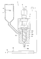
図1は、液晶表示装置の製造に用いられる塗布装置1の構成を示す概略構成図である。
図2は、ディスペンサーユニット5の要部を拡大して示す図である。
図1に示す本実施形態の塗布装置1は、液晶表示装置の製造方法に用いられるスクリュー方式の塗布装置である。塗布装置1は、シール材(粘性材料)4の被塗布対象物である基板Wを水平状態で載置させるステージ2と、ステージ2上に載置された基板(塗布対象物)Wに対してシール材4を吐出するディスペンサーユニット5と、ディスペンサーユニット5に供給するシール材4を貯留するシール材貯留部6と、を少なくとも備えて構成されている。
図1は、液晶表示装置の製造に用いられる塗布装置1の構成を示す概略構成図である。
図2は、ディスペンサーユニット5の要部を拡大して示す図である。
図1に示す本実施形態の塗布装置1は、液晶表示装置の製造方法に用いられるスクリュー方式の塗布装置である。塗布装置1は、シール材(粘性材料)4の被塗布対象物である基板Wを水平状態で載置させるステージ2と、ステージ2上に載置された基板(塗布対象物)Wに対してシール材4を吐出するディスペンサーユニット5と、ディスペンサーユニット5に供給するシール材4を貯留するシール材貯留部6と、を少なくとも備えて構成されている。
また、塗布装置1は、さらにディスペンサーユニット5とステージ2とを相対的に移動させる移動機構と、ステージ2およびディスペンサーユニット5の動作を制御する制御装置7と、を備えている。なお、塗布装置1のうち、ディスペンサーユニット5、制御装置7以外の一般的な構成については図示及び説明を省略する。
(ディスペンサーユニット5)
ディスペンサーユニット5は、図1および図2に示すように、シリンダ51と、シリンダ51内に配置されたスクリューロッド52と、スクリューロッド52を回転させるモーター53と、シリンダ51の下端側に連通する吐出ノズル54と、を有している。
ディスペンサーユニット5は、図1および図2に示すように、シリンダ51と、シリンダ51内に配置されたスクリューロッド52と、スクリューロッド52を回転させるモーター53と、シリンダ51の下端側に連通する吐出ノズル54と、を有している。
シリンダ51は、ステージ2の上方に配置され、ステージ2の基板載置面2aに対して垂直な方向へ延在している。シリンダ51は、スクリューロッド52が収容される液室51Aを有した中空部材である。スクリューロッド52の中心軸とシリンダ51の中心軸とは一致する。液室51A内におけるシリンダ51の周壁部51bとスクリューロッド52との間の隙間は、シール材貯留部6から供給されるシール材4によって満たされることになる。
シリンダ51の周壁部51bには、シール材貯留部6に連通する供給口51cが形成されており、この供給口51cを介して、シール材貯留部6から供給されたシール材4がシリンダ51の液室51A内へ流入する。シリンダ51の下端には、軸方向の先端(-Z方向)側へ行くにしたがって縮径するテーパー部51dが存在しており、その先端中央に、液室51A内のシール材4を吐出するための吐出ノズル54が設けられている。
スクリューロッド52は、シリンダ51内において回転自在に配置されている。スクリューロッド52は、中実円柱形状をした棒状のシャフト52Aと、シャフト52Aの外周面52aに設けられた1条の螺旋状の凸条部52Bと、この螺旋状の凸条部52Bによって形成される凹条部52Cとを有してなる。中心軸に対する凸条部52Bの螺旋角度θは、10度以上80度以下である。スクリューロッド52の下端には、軸方向の先端(-Z方向)側へ行くにしたがって縮径するテーパー部52dが存在し、そのテーパー面は上述したシリンダ51のテーパー部51dのテーパー面に略平行する。
このようなスクリューロッド52は、螺旋状の凹条部52C内までシール材4で満たされた液室51Aから吐出ノズル54へ向けてシール材4(図1)を搬送する。つまり、スクリューロッド52が回転軸Oの周りに回転することにより、凸条部52Bによって液室51A内のシール材4が吐出ノズル54へ向けて軸方向へ押し出されるように搬送される。
吐出ノズル54は、スクリューロッド52によって搬送されるシリンダ51の液室51A内のシール材4を、ステージ2に載置された基板W上へ吐出するためのノズルである。
吐出ノズル54は、シリンダ51およびスクリューロッド52と同心円状に配置されている。吐出ノズル54の吐出口54aは、スクリューロッド52の軸方向に交差する方向の断面に平行である。そのため、スクリューロッド52により軸方向へ送り出されたシール材4がその延長上に位置する吐出口54aからスムーズに吐出される。
吐出ノズル54は、シリンダ51およびスクリューロッド52と同心円状に配置されている。吐出ノズル54の吐出口54aは、スクリューロッド52の軸方向に交差する方向の断面に平行である。そのため、スクリューロッド52により軸方向へ送り出されたシール材4がその延長上に位置する吐出口54aからスムーズに吐出される。
モーター53の駆動制御を行うことによって、スクリューロッド52の回転速度を凸条部52Bの位置に応じて決定することができる。これにより、シール材4の脈動が抑えられて、一定量で吐出させることができる。
制御装置7は、移動機構の動作と、ディスペンサーユニット5の動作とを調整する。
制御装置7は、ディスペンサーユニット5とステージ2とを一定速度で相対移動させて塗布を行う際に、スクリューロッド52の回転数を変化させる。なお、ディスペンサーユニット5とステージ2との相対速度は、常に一定でなくてもよく、直線描画、曲線描画、コーナー描画等に応じて適宜変更してもよい。
制御装置7は、ディスペンサーユニット5とステージ2とを一定速度で相対移動させて塗布を行う際に、スクリューロッド52の回転数を変化させる。なお、ディスペンサーユニット5とステージ2との相対速度は、常に一定でなくてもよく、直線描画、曲線描画、コーナー描画等に応じて適宜変更してもよい。
[シール材の塗布方法]
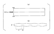
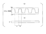
図3(a)は、スクリューロッド52の回転数(一定)を示し、図3(b)は、スクリューロッド52の回転数を一定にしてシール材4を塗布した場合のシール材4の仕上がり状態を示す平面図である。図4(a)は、スクリューロッド52の回転数(変動)を示し、図3(b)は、スクリューロッド52の回転数を変動させてシール材4を塗布した場合のシール材4の仕上がり状態を示す平面図である。
図3(a)は、スクリューロッド52の回転数(一定)を示し、図3(b)は、スクリューロッド52の回転数を一定にしてシール材4を塗布した場合のシール材4の仕上がり状態を示す平面図である。図4(a)は、スクリューロッド52の回転数(変動)を示し、図3(b)は、スクリューロッド52の回転数を変動させてシール材4を塗布した場合のシール材4の仕上がり状態を示す平面図である。
例えば、液晶表示装置を製造する際には、本実施形態の塗布装置1を用いて、互いに対向して配置される一対の基板のうち一方の基板W上に、表示領域を囲むようにして長方形状の閉ループのパターンを形成するライン塗布を行う。
スクリュー方式の塗布装置1では、まず始めに初期充填動作が行われ、その後、塗布動作が行われる。
初期充填動作は、スクリューロッド52を回転させることにより、シリンダ51の周壁部51bとスクリューロッド52との間に形成される螺旋状の隙間に、空気を残留させることなくシール材4を充填するための動作である。
塗布動作は、スクリューロッド52の回転量に応じたシール材4を吐出ノズル54から連続的に押し出して、基板W上に所望のパターン描画を行うための動作である。
初期充填動作は、スクリューロッド52を回転させることにより、シリンダ51の周壁部51bとスクリューロッド52との間に形成される螺旋状の隙間に、空気を残留させることなくシール材4を充填するための動作である。
塗布動作は、スクリューロッド52の回転量に応じたシール材4を吐出ノズル54から連続的に押し出して、基板W上に所望のパターン描画を行うための動作である。
塗布装置1の制御装置7は、モーター53を駆動してシリンダ51内のスクリューロッド52を回転させることにより、シリンダ51の周壁部51bと螺旋状の凹条部52Cとの間のシール材4を凸条部52Bにより軸方向へ押し出して、テーパー部52dに形成された凹条部52Cの開口部52eから吐出ノズル54側へと移送し、吐出ノズル54からステージ2上に載置された基板Wに向かって吐出させる。吐出ノズル54から吐出させたシール材4を基板W上に塗布することにより、閉ループのシールパターンを形成する。
このような塗布装置1では、スクリューロッド52が回転することによってシール材4が押し出されるが、スクリューロッド52の回転位置によって、凸条部52Bの径方向両側の第1位置A1および第2位置A2のそれぞれと吐出ノズル54の吐出口54aとの間の距離L1,L2(図1)が異なるため、図3(a)に示すようにモーター53の回転数を一定にしてスクリューロッド52を等速で回転させると、図3(b)に示すように押出圧力が変動してシール材4の吐出量にバラツキが生じてしまう。このように、スクリューロッド52を一定の速度で回転させる場合には、スクリューロッド52の回転位置(回転角度)によって凸条部52Bによる押出圧力(シール材4の抵抗)の変動が生じ、これによってシール材4の吐出量に脈動が生じてしまう。そのため、これを改善する必要がある。
そこで本実施形態では、図4(a)に示すように、制御装置7においてモーター53の回転数をスクリューロッド52の回転位置、つまり上述した押出圧力に応じて変動させ、スクリューロッド52の回転速度を変化させる制御を行った。ここでは、スクリューロッド52における押出圧力が低い位置(シール材4の抵抗が低い)では回転数を上げて吐出量を多くし、押出圧力が高い位置(シール材4の抵抗が高い)では回転数を下げることで吐出量を少なくする制御を行った。その結果、図4(b)に示すようにシール材4の吐出量のバラツキが改善され、直進性の高い仕上がりでシール材4を塗布することができた。
ディスペンサーユニット5から吐出されるシール材4の単位時間当たりの吐出量は、スクリューロッド52の回転数に比例する。そのため、スクリューロッド52の回転数を調整することにより、吐出ノズル54から吐出されるシール材4の吐出量が一定となるように調整することが可能である。
また、本実施形態の塗布装置1は、スクリューロッド52の回転位置を検出する検出手段を備えていてもよい。検出手段としては種々の手段が挙げられるが、例えば、スクリューロッド52の凸条部52Bにおける径方向両側の第1位置A1と第2位置A2とをセンサ等を用いて検出し、その結果に基づいて制御装置7がモーター53の回転数を制御するようにしてもよい。
スクリューロッド52の回転位置(第1位置A1および第2位置A2の位置)を把握することにより、スクリューロッド52によるシール材4の押出圧力(シール材4の抵抗)が変わっても、最適な吐出量になるようスクリューロッド52の回転数を変動させてシール材4の突出量が一定となるようにできる。
上述したように、本実施形態の塗布装置1によれば、スクリューロッド52の回転位置(シール材4の抵抗)に応じてその回転数を制御することによって、シール材4を一定の吐出量で安定して突出させることができるため、吐出量の脈動が抑えられてシール材4を直線状に描画できる。これにより、シール材4の全体において接着強度が一定となってパネル強度を十分に確保することができる。また、基板W上に塗布されたシール材4の直進性が向上することで、シール材4の細線化が可能になる。そのため、液晶パネルの狭額縁化に伴って狭くなったシール形成領域内に良好に塗布することができるため、他の領域を侵すことがなく、良好な表示が行える液晶パネルを得ることができる。
以上、添付図面を参照しながら本発明に係る好適な実施形態について説明したが、本発明は係る例に限定されないことは言うまでもない。当業者であれば、特許請求の範囲に記載された技術的思想の範疇内において、各種の変更例または修正例に想到し得ることは明らかであり、それらについても当然に本発明の技術的範囲に属するものと了解される。
本発明のいくつかの態様は、シール材の塗布量のバラツキを改善することが必要な塗布装置および塗布方法などに適用することができる。
1…塗布装置、2…ステージ、4…シール材(粘性材料)、5…ディスペンサーユニット、7…制御装置、51…シリンダ、51A…液室、52,62…スクリューロッド、52A…シャフト、52a…外周面、52B…凸条部、52C…凹条部、53…モーター、54…吐出ノズル、54a…吐出口、W…基板(塗布対象物)
Claims (4)
- 粘性材料を塗布対象物に向けて吐出するディスペンサーユニットと、
前記塗布対象物を載置するステージと、
前記ディスペンサーユニットと前記ステージとを相対移動させる移動機構と、
前記ディスペンサーユニットおよび前記移動機構を制御する制御装置と、を備え、
前記ディスペンサーユニットは、
液室を有するシリンダと、
前記シリンダの下端に設けられ、前記液室内の前記粘性材料を塗布対象物に向けて吐出する吐出ノズルと、
前記液室内に配置され、回転することにより前記液室内の前記粘性材料を前記吐出ノズルへ向けて軸方向へ送り出すスクリューロッドと、
前記スクリューロッドを回転させるモーターと、を備え、
前記スクリューロッドは、シャフトと、前記シャフトの外周面に設けられた螺旋状の凸条部と、前記凸条部によって形成される螺旋状の凹条部と、を有し、
前記制御装置は、前記スクリューロッドの回転位置に応じて前記モーターの回転数を制御する、塗布装置。 - 前記吐出ノズルは、前記シリンダおよび前記スクリューロッドと同心円状に設けられ、前記スクリューロッドの軸方向に交差する方向の断面に平行する吐出口を有し、
前記スクリューロッドの径方向両側における前記凸条部の第1位置および第2位置のそれぞれと前記吐出口との間の軸方向における距離が互いに異なっている、請求項1に記載の塗布装置。 - 請求項1または2のいずれか一項に記載の塗布装置を用いて塗布対象物に粘性材料を塗布する塗布方法において、
上記ディスペンサーユニットのスクリューロッドの回転位置を把握し、前記回転位置に応じて前記スクリューロッドの回転数を制御する、塗布方法。 - 前記ディスペンサーユニットから吐出される前記粘性材料の抵抗が大きくなる位置では前記スクリューロッドの前記回転数を上げ、前記粘性材料の抵抗が小さくなる位置では前記スクリューロッドの前記回転数を下げる制御を行う、請求項3に記載の塗布方法。
Applications Claiming Priority (2)
| Application Number | Priority Date | Filing Date | Title |
|---|---|---|---|
| JP2017135586 | 2017-07-11 | ||
| JP2017-135586 | 2017-07-11 |
Publications (1)
| Publication Number | Publication Date |
|---|---|
| WO2019013208A1 true WO2019013208A1 (ja) | 2019-01-17 |
Family
ID=65001391
Family Applications (1)
| Application Number | Title | Priority Date | Filing Date |
|---|---|---|---|
| PCT/JP2018/026054 Ceased WO2019013208A1 (ja) | 2017-07-11 | 2018-07-10 | 塗布装置および塗布方法 |
Country Status (1)
| Country | Link |
|---|---|
| WO (1) | WO2019013208A1 (ja) |
Cited By (1)
| Publication number | Priority date | Publication date | Assignee | Title |
|---|---|---|---|---|
| CN119634150A (zh) * | 2024-10-30 | 2025-03-18 | 西安建筑科技大学 | 一种摩擦涂覆耐高温高熵合金涂层制备装置及方法 |
Citations (5)
| Publication number | Priority date | Publication date | Assignee | Title |
|---|---|---|---|---|
| JPH0449108A (ja) * | 1990-06-18 | 1992-02-18 | Iwashita Eng Kk | スクリュー式吐出装置 |
| JP2005185916A (ja) * | 2003-12-25 | 2005-07-14 | Sony Corp | スクリュー式ディスペンサー |
| WO2006118088A1 (ja) * | 2005-04-26 | 2006-11-09 | Shibaura Mechatronics Corporation | ペースト塗布装置及びペースト塗布方法 |
| JP2009039661A (ja) * | 2007-08-09 | 2009-02-26 | Shibaura Mechatronics Corp | ペースト塗布装置及びペースト塗布方法 |
| JP2009050828A (ja) * | 2007-08-29 | 2009-03-12 | Shibaura Mechatronics Corp | ペースト塗布装置及びペースト塗布方法 |
-
2018
- 2018-07-10 WO PCT/JP2018/026054 patent/WO2019013208A1/ja not_active Ceased
Patent Citations (5)
| Publication number | Priority date | Publication date | Assignee | Title |
|---|---|---|---|---|
| JPH0449108A (ja) * | 1990-06-18 | 1992-02-18 | Iwashita Eng Kk | スクリュー式吐出装置 |
| JP2005185916A (ja) * | 2003-12-25 | 2005-07-14 | Sony Corp | スクリュー式ディスペンサー |
| WO2006118088A1 (ja) * | 2005-04-26 | 2006-11-09 | Shibaura Mechatronics Corporation | ペースト塗布装置及びペースト塗布方法 |
| JP2009039661A (ja) * | 2007-08-09 | 2009-02-26 | Shibaura Mechatronics Corp | ペースト塗布装置及びペースト塗布方法 |
| JP2009050828A (ja) * | 2007-08-29 | 2009-03-12 | Shibaura Mechatronics Corp | ペースト塗布装置及びペースト塗布方法 |
Cited By (2)
| Publication number | Priority date | Publication date | Assignee | Title |
|---|---|---|---|---|
| CN119634150A (zh) * | 2024-10-30 | 2025-03-18 | 西安建筑科技大学 | 一种摩擦涂覆耐高温高熵合金涂层制备装置及方法 |
| CN119634150B (zh) * | 2024-10-30 | 2025-09-23 | 西安建筑科技大学 | 一种摩擦涂覆耐高温高熵合金涂层制备装置及方法 |
Similar Documents
| Publication | Publication Date | Title |
|---|---|---|
| KR101523294B1 (ko) | 액체 재료의 도포 장치, 도포 방법 및 프로그램이 기억된 기억 매체 | |
| JP6804850B2 (ja) | 塗布装置及び塗布方法 | |
| CN101362125A (zh) | 涂膏装置以及涂膏方法 | |
| JP5304902B2 (ja) | 電池の電極の製造方法および電池の電極の製造装置 | |
| EP1872861A2 (en) | Method and apparatus for applying coating solution with bar | |
| WO2015033535A1 (ja) | 流体塗布システムおよび流体塗布方法 | |
| JP2009050828A (ja) | ペースト塗布装置及びペースト塗布方法 | |
| WO2019013208A1 (ja) | 塗布装置および塗布方法 | |
| JP6408608B2 (ja) | 塗布装置と塗布方法、塗布ユニット | |
| WO2022050077A1 (ja) | 塗布装置 | |
| JP2008253867A (ja) | 塗布装置 | |
| JP5251233B2 (ja) | 筒体の塗装方法 | |
| JP2021098154A (ja) | 塗布装置及び塗布方法 | |
| ES2982962T3 (es) | Procedimiento y dispositivo de deposición de un cordón de fluido viscoso a alta velocidad | |
| JP2016067974A (ja) | 塗布装置および塗布方法 | |
| JP5335319B2 (ja) | 塗布装置及び塗布方法 | |
| JP2002079164A (ja) | エクストルージョン型ノズル、塗布装置、並びにプラズマディスプレイパネル前面板の誘電体層の製造方法 | |
| JP5127127B2 (ja) | 塗膜形成方法 | |
| JP6901616B2 (ja) | 塗布装置及び塗布方法 | |
| JP2006035179A (ja) | 塗工装置 | |
| JP4868404B2 (ja) | 処理方法および処理装置 | |
| JP2021186692A (ja) | 樹脂の塗布制御方法及び樹脂塗布装置 | |
| JP4619161B2 (ja) | 塗布装置 | |
| JP3161694U (ja) | 塗工装置 | |
| KR20010109589A (ko) | 립 코터형 도장장치 |
Legal Events
| Date | Code | Title | Description |
|---|---|---|---|
| 121 | Ep: the epo has been informed by wipo that ep was designated in this application |
Ref document number: 18831032 Country of ref document: EP Kind code of ref document: A1 |
|
| NENP | Non-entry into the national phase |
Ref country code: DE |
|
| 122 | Ep: pct application non-entry in european phase |
Ref document number: 18831032 Country of ref document: EP Kind code of ref document: A1 |
|
| NENP | Non-entry into the national phase |
Ref country code: JP |