WO2019013151A1 - 無人航空機の飛行高度設定方法および無人航空機システム - Google Patents
無人航空機の飛行高度設定方法および無人航空機システム Download PDFInfo
- Publication number
- WO2019013151A1 WO2019013151A1 PCT/JP2018/025826 JP2018025826W WO2019013151A1 WO 2019013151 A1 WO2019013151 A1 WO 2019013151A1 JP 2018025826 W JP2018025826 W JP 2018025826W WO 2019013151 A1 WO2019013151 A1 WO 2019013151A1
- Authority
- WO
- WIPO (PCT)
- Prior art keywords
- height
- altitude
- flight
- unmanned aerial
- aerial vehicle
- Prior art date
- Legal status (The legal status is an assumption and is not a legal conclusion. Google has not performed a legal analysis and makes no representation as to the accuracy of the status listed.)
- Ceased
Links
Images


Classifications
-
- G—PHYSICS
- G05—CONTROLLING; REGULATING
- G05D—SYSTEMS FOR CONTROLLING OR REGULATING NON-ELECTRIC VARIABLES
- G05D1/00—Control of position, course, altitude or attitude of land, water, air or space vehicles, e.g. using automatic pilots
- G05D1/10—Simultaneous control of position or course in three dimensions
- G05D1/101—Simultaneous control of position or course in three dimensions specially adapted for aircraft
-
- G—PHYSICS
- G05—CONTROLLING; REGULATING
- G05D—SYSTEMS FOR CONTROLLING OR REGULATING NON-ELECTRIC VARIABLES
- G05D1/00—Control of position, course, altitude or attitude of land, water, air or space vehicles, e.g. using automatic pilots
- G05D1/04—Control of altitude or depth
- G05D1/06—Rate of change of altitude or depth
- G05D1/0607—Rate of change of altitude or depth specially adapted for aircraft
- G05D1/0646—Rate of change of altitude or depth specially adapted for aircraft to follow the profile of undulating ground
-
- G—PHYSICS
- G01—MEASURING; TESTING
- G01C—MEASURING DISTANCES, LEVELS OR BEARINGS; SURVEYING; NAVIGATION; GYROSCOPIC INSTRUMENTS; PHOTOGRAMMETRY OR VIDEOGRAMMETRY
- G01C21/00—Navigation; Navigational instruments not provided for in groups G01C1/00 - G01C19/00
- G01C21/26—Navigation; Navigational instruments not provided for in groups G01C1/00 - G01C19/00 specially adapted for navigation in a road network
-
- G—PHYSICS
- G08—SIGNALLING
- G08G—TRAFFIC CONTROL SYSTEMS
- G08G5/00—Traffic control systems for aircraft
-
- B—PERFORMING OPERATIONS; TRANSPORTING
- B64—AIRCRAFT; AVIATION; COSMONAUTICS
- B64U—UNMANNED AERIAL VEHICLES [UAV]; EQUIPMENT THEREFOR
- B64U10/00—Type of UAV
- B64U10/10—Rotorcrafts
- B64U10/13—Flying platforms
-
- B—PERFORMING OPERATIONS; TRANSPORTING
- B64—AIRCRAFT; AVIATION; COSMONAUTICS
- B64U—UNMANNED AERIAL VEHICLES [UAV]; EQUIPMENT THEREFOR
- B64U2101/00—UAVs specially adapted for particular uses or applications
- B64U2101/30—UAVs specially adapted for particular uses or applications for imaging, photography or videography
-
- B—PERFORMING OPERATIONS; TRANSPORTING
- B64—AIRCRAFT; AVIATION; COSMONAUTICS
- B64U—UNMANNED AERIAL VEHICLES [UAV]; EQUIPMENT THEREFOR
- B64U2101/00—UAVs specially adapted for particular uses or applications
- B64U2101/40—UAVs specially adapted for particular uses or applications for agriculture or forestry operations
-
- B—PERFORMING OPERATIONS; TRANSPORTING
- B64—AIRCRAFT; AVIATION; COSMONAUTICS
- B64U—UNMANNED AERIAL VEHICLES [UAV]; EQUIPMENT THEREFOR
- B64U2101/00—UAVs specially adapted for particular uses or applications
- B64U2101/45—UAVs specially adapted for particular uses or applications for releasing liquids or powders in-flight, e.g. crop-dusting
-
- B—PERFORMING OPERATIONS; TRANSPORTING
- B64—AIRCRAFT; AVIATION; COSMONAUTICS
- B64U—UNMANNED AERIAL VEHICLES [UAV]; EQUIPMENT THEREFOR
- B64U2201/00—UAVs characterised by their flight controls
- B64U2201/10—UAVs characterised by their flight controls autonomous, i.e. by navigating independently from ground or air stations, e.g. by using inertial navigation systems [INS]
- B64U2201/104—UAVs characterised by their flight controls autonomous, i.e. by navigating independently from ground or air stations, e.g. by using inertial navigation systems [INS] using satellite radio beacon positioning systems, e.g. GPS
-
- B—PERFORMING OPERATIONS; TRANSPORTING
- B64—AIRCRAFT; AVIATION; COSMONAUTICS
- B64U—UNMANNED AERIAL VEHICLES [UAV]; EQUIPMENT THEREFOR
- B64U30/00—Means for producing lift; Empennages; Arrangements thereof
- B64U30/20—Rotors; Rotor supports
-
- B—PERFORMING OPERATIONS; TRANSPORTING
- B64—AIRCRAFT; AVIATION; COSMONAUTICS
- B64U—UNMANNED AERIAL VEHICLES [UAV]; EQUIPMENT THEREFOR
- B64U50/00—Propulsion; Power supply
- B64U50/10—Propulsion
- B64U50/19—Propulsion using electrically powered motors
Definitions
- the present invention relates to unmanned aerial vehicle technology.
- Patent Document 1 discloses a model aircraft that automatically maintains the flight altitude at a set flight altitude.
- a small unmanned aerial vehicle represented by a multicopter is provided with a control device called a flight controller that controls the flight operation of the airframe.
- a flight controller that controls the flight operation of the airframe.
- Some flight controller products distributed in the market have an autopilot function.
- the autopilot function is a function of automatically maintaining the attitude and flight position of the unmanned aircraft, and autonomously flying the unmanned aircraft based on a flight plan created by the pilot.
- a typical autopilot flight plan can specify the take-off and landing points of the airframe, the latitude and longitude of the flight route, the altitude, the speed, the azimuth of the nose, etc.
- some flight controllers specialized for aerial photography may be able to specify start / end of shooting by a camera, PTZ, and the like.
- Such a flight controller includes an air pressure sensor, a distance sensor using laser and ultrasonic waves, or an image recognition means using a camera in order to control the flight altitude in flight.
- the altitude of the ground surface or the feature is not considered because the flight altitude is determined based on the barometric pressure altitude, not on the ground altitude. Therefore, for example, in order to cause the unmanned aircraft to fly along the slope of the mountain surface, it is necessary to investigate the undulations of the mountain surface beforehand and manually specify the flight height on the flight path one by one.
- the distance measurement sensor and the image recognition means it is possible to control the flight altitude based on the relative distance to the ground surface and features at the place and place.
- the flying height is not stable because the relative distance fluctuates in a narrow range.
- the problem to be solved by the present invention is to provide a flight altitude setting method and an unmanned aircraft system capable of efficiently setting the flight altitude of a flight plan according to the unevenness or inclination of the ground surface or a feature. It is in.
- the flight altitude setting method of an unmanned aerial vehicle comprises: an undulation survey step of flying the unmanned aerial vehicle and measuring the height of the ground or feature; and specifying a route for autonomously flying the unmanned aerial vehicle
- An altitude setting step of automatically setting a flight altitude on a route of the flight plan based on the height of the ground surface or the feature measured in the relief survey process when creating the flight plan which is setting data including It is characterized by including.
- the unmanned aerial vehicle By flying the unmanned aerial vehicle and measuring the height of the ground surface or feature in the relief survey process, it becomes possible to set the flight height based on the actual topography at that time. Then, in the altitude setting step of the present invention, the flight altitude of the flight plan is automatically set based on the measurement results of the relief survey step, so that the operator can save time and effort for calculating and inputting a suitable flight altitude. Also, in the present invention, it is assumed that the unmanned aerial vehicle is autonomously operated based on the flight plan created in the altitude setting process and the unmanned aerial vehicle is made to do some work. Or by using it also for measuring the height of features, it is not necessary to prepare a separate surveying instrument etc. for surveying.
- the altitude above sea level acquired using the altitude sensor mounted on the unmanned aerial vehicle or the relative altitude from the takeoff point of the unmanned aerial vehicle, and the distance measurement sensor directed downward from the unmanned aerial vehicle it is preferable to measure the height of the ground surface or the feature based on the ground height obtained using the photographing means.
- An unmanned aerial vehicle is equipped with an altitude sensor and a distance measurement sensor or imaging means, and it is possible to calculate the height of the surface or feature on the flight path by subtracting the ground altitude from the relative altitude from the takeoff point or the altitude above sea level. It is possible to easily identify the height of the ground surface or feature by being present. Furthermore, the control accuracy of flight altitude can be improved by controlling the flight altitude of the unmanned aircraft in flight using these two altitudes.
- a flight plan is specified in which a route for causing the unmanned aircraft to autonomously fly is specified by a flight altitude having a margin to the ground surface or feature height on the route.
- the method further includes a provisional route setting step of creating, in the relief research step, autonomous flight of the unmanned aircraft according to the flight plan created in the tentative route setting step, and the height of the surface or feature on the route of the flight plan. It is preferable to measure the height.
- the flight plan created in the temporary route setting process and the flight plan created in the altitude setting process have substantially the same routes on the latitude and longitude.
- the route of the flight plan created in the provisional route setting process that is, the latitude and longitude of the route for flying the unmanned aircraft in the relief survey process and the latitude and longitude of the route specified in the altitude setting process are substantially the same.
- the measurement range of the survey process can be narrowed down to only the actually required range. As a result, the process of investigating the unevenness can be made efficient, and the coverage of the automatically settable range in the advanced setting process can be increased.
- the method for setting flight altitude of an unmanned aerial vehicle further includes a target distance setting step of specifying a target distance which is a ground altitude to be maintained by the unmanned aircraft, and the altitude setting step measures in the relief survey step. It is preferable to automatically set a height obtained by adding the target distance to the height of the ground surface or feature obtained as the flight height on the path of the flight plan.
- the unmanned aerial vehicle is autonomously fly according to the flight plan created in the altitude setting step, and the height of the surface or feature on the route of the flight plan is measured.
- An elevation re-set process which automatically sets a height obtained by adding the target distance to the height of the surface or feature measured in the re-survey process and the re-survey process in the re-survey process as the flight height on the route of the flight plan It is preferable to further include and.
- the unmanned aerial vehicle system of the present invention includes an unmanned aerial vehicle and a management device for creating a flight plan which is setting data including designation of a route for autonomously flying the unmanned aerial vehicle;
- An unmanned aerial vehicle or the management device is an autonomous flight control means for autonomously flying the unmanned aerial vehicle based on the flight plan, and an undulation acquiring means for calculating the height of a surface or a feature of a path where the unmanned aerial vehicle is caused to fly.
- the management device automatically sets the flight altitude on the path of the flight plan based on the height of the ground surface or the feature calculated by the relief acquisition means at the time of creating the flight plan. It is characterized by having an altitude setting means.
- the unmanned aerial vehicle system of the present invention can set the flight altitude based on the actual topography on which the unmanned aerial vehicle is to fly by having the relief acquisition means for calculating the height of the ground surface or the feature. Then, the altitude setting means automatically sets the flight altitude of the flight plan based on the calculation result of the relief acquisition means, so that the time and effort for the pilot to calculate and input a suitable flight altitude can be saved. Further, in the present invention, it is assumed that the unmanned aerial vehicle is autonomously fly using the flight plan whose flight altitude is set by the altitude setting means, and the unmanned aerial vehicle is to perform some work. By using the unmanned aerial vehicle also for measuring the height of the ground surface or features, it is not necessary to prepare a separate survey instrument etc. to conduct surveys.
- the problem of the time and cost of the surveying operation and the problem of obsolescence of the survey data due to the passage of time do not occur. Further, small reliefs and inclinations of several meters, which can not be grasped by a map or the like, can be obtained on the spot, so that the flight altitude more accurately can be designated.
- the unmanned aerial vehicle includes an altitude sensor for acquiring an altitude above sea level or a relative altitude from a takeoff point, and distance information acquiring means for acquiring information capable of measuring a distance to the ground or a feature;
- the aircraft or the management apparatus has distance measuring means for calculating the ground altitude of the unmanned aircraft from the information acquired by the distance information acquiring means, and the relief acquiring means is the sea level altitude or the takeoff point acquired by the altitude sensor It is preferable to calculate the height of the ground surface or the feature on the basis of the relative height from the ground and the ground height acquired by the distance measuring means.
- a surface or feature by being provided with an altitude sensor and distance measuring means, and being able to calculate the height of the surface or feature on the flight path by subtracting the ground altitude from the relative altitude from the takeoff point or the altitude above sea level It is possible to easily identify the height of the
- the management device has a target distance holding unit that stores a target distance which is a ground altitude to be maintained by the unmanned aerial vehicle, and the height setting means adds the target distance to the height of the ground surface or the feature.
- the height is automatically set as the flight altitude on the flight plan route.
- the unmanned aerial vehicle system of the present invention can be flexibly applied to a wide range of applications.
- the flight altitude setting method and the unmanned aerial vehicle system of the present invention it is possible to efficiently set the flight altitude of the unmanned aerial vehicle with respect to the unevenness or inclination of the ground surface or the feature.
- This embodiment is an example of an operation of spraying pesticides on orchards formed on the slope of a mountain ridge using an unmanned aerial system S consisting of a multi-copter 10 which is a small unmanned rotary wing aircraft and a management device 60. .
- FIG. 1 is a schematic view showing a pesticide spraying operation using the unmanned aerial vehicle system S.
- the multicopter 10 is a mountain surface which is the ground surface or a fruit tree which is a feature (hereinafter, these are collectively referred to as “fruit trees g”) along a route r designated in advance. Autonomously fly at a predetermined flying height a and spray pesticides on the top.
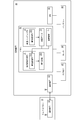
- FIG. 2 is a block diagram showing the functional configuration of the multicopter 10.
- the multicopter 10 mainly receives a control signal from the flight controller 11, which is a control unit, the management device 60 carried by the operator, and transmits / receives data to / from the management device 60.
- the flight controller 11 which is a control unit
- the management device 60 carried by the operator
- ESC 131 Electric Speed Controller
- camera 40 is a photographing means for photographing fruit trees and the like under the machine, and electric power is supplied to these It is comprised by the battery 19 to supply.
- the flight controller 11 includes a control device 20 which is a microcontroller.
- the control device 20 controls the number of rotations of each rotor 13 via a CPU 21 which is a central processing unit, a memory 22 including a storage device such as a RAM and a ROM / flash memory, and PWM (Pulse Width Modulation: pulse width Modulation) controller 23 is provided.
- a CPU 21 which is a central processing unit
- a memory 22 including a storage device such as a RAM and a ROM / flash memory
- PWM Pulse Width Modulation: pulse width Modulation
- the flight controller 11 further includes a flight control sensor group 30 including an IMU 31 (Inertial Measurement Unit: inertial measurement device), a GPS antenna 32, an air pressure sensor 33, and an electronic compass 34, which are connected to the control device 20. ing.
- IMU 31 Inertial Measurement Unit: inertial measurement device
- GPS antenna 32 GPS antenna
- air pressure sensor 33 air pressure sensor
- electronic compass 34 electronic compass
- the IMU 31 mainly includes a 3-axis acceleration sensor and a 3-axis angular velocity sensor.
- the GPS antenna 32 is precisely a receiver of a navigation satellite system (NSS).
- the GPS antenna 32 acquires current longitude and latitude values and time information from a Global Navigation Satellite System (GNSS) or a Regional Navigational Satellite System (RNSS).
- GNSS Global Navigation Satellite System
- RNSS Regional Navigational Satellite System
- the atmospheric pressure sensor 33 is an aspect of the altitude sensor that measures the flight altitude.
- the barometric pressure sensor 33 specifies the flying height of the multicopter 10 by converting the detected barometric pressure value to a sea level altitude or a relative height from the takeoff point of the multicopter 10.
- the height sensor according to the present invention is not limited to the barometric pressure sensor 33.
- the electronic compass 34 is an aspect of an azimuth sensor that measures the azimuth angle of the nose.
- a three-axis geomagnetic sensor is used for the electronic compass 34 in this example.
- the control device 20 is capable of acquiring the position information of its own aircraft including the latitude and longitude in flight, altitude, and the azimuth angle of the nose as well as the tilt and rotation of the airframe by these flight control sensors 30. ing.
- the control device 20 has a flight control program 221 which is a program for controlling the attitude of the multicopter 10 during flight and basic flight operations.
- the flight control program 221 adjusts the number of revolutions of each rotor 13 based on the information acquired from the flight control sensor group 30, and causes the multicopter 10 to fly while correcting the attitude and position disorder of the airframe.
- the control device 20 of this example further includes an autonomous flight program 222 which is an autonomous flight control means of the multicopter 10.
- the autonomous flight program 222 is a program for autonomously flying the multicopter 10 based on a flight plan 223 which is setting data such as a route r for causing the multicopter 10 to fly, altitude a, and the like.
- path r means a flight path on a horizontal surface (longitudinal and longitudinal).
- the autonomous flight program 222 autonomously flies the multicopter 10 based on the flight plan 223, with an execution instruction from the pilot (management device 60) and a predetermined time as a start condition. In this example, such an autonomous flight is referred to as "autopilot".
- the multicopter 10 is made to fly by an autopilot, but it is also possible for the pilot to steer manually using the management device 60.
- the autonomous flight control means is mounted on the multicopter 10 in this example, the management apparatus 60 is provided with the autonomous flight control means, and the autopilot can be performed by operating the multicopter 10 remotely by wireless communication. It is possible.
- the camera 40 continuously captures (continuously captures) a still image below the airframe at constant distance intervals while the multicopter 10 is flying.
- information of the latitude and longitude of the multicopter 10 at that imaging position and the flying height is added.
- These pieces of additional information are information obtained by the GPS antenna 32 and the pressure sensor 33 of the multicopter 10.
- the respective images are taken at an interval at which a part of the image of a fruit tree or the like g contained within the angle of view of the camera 40 overlaps in the traveling direction of the multicopter 10.
- Each of these images is analyzed by an image recognition program 721 of the management device 60 described later, whereby the distance (ground height) between the multicopter 10 (camera 40) and the fruit tree etc.
- the camera 40 of this example is distance information acquisition means for acquiring information capable of measuring the distance between the multicopter 10 and the fruit tree or the like g.
- the camera 40 of this example is configured to record the captured image and its additional information in the memory 41 such as an SD memory card included in the camera 40, the management device manages this in real time through the communication device 12. It may be configured to transmit to 60.
- the camera 40 is employ
- the distance information acquisition means of this invention is a means to acquire the information which can measure the distance of an unmanned aerial vehicle and the ground surface or a terrestrial feature.
- an optical distance measuring sensor such as a laser distance measuring sensor or an ultrasonic sensor may be employed.
- FIG. 3 is a block diagram showing a functional configuration of the management device 60.
- the management device 60 is a terminal that performs various settings, status monitoring, and maneuvering of the multicopter 10, and is a device generally called a GCS (Ground Control Station) in the unmanned aerial vehicle field.
- GCS Gate Control Station
- the management device 60 mainly includes a CPU 61 which is a central processing unit, a memory 62 including a storage device such as a RAM and a ROM / flash memory, a communication device 63 which wirelessly communicates with the multicopter 10, and various information visually displayed to the operator. And an input device 65 for receiving input from the operator, and a battery 69 for supplying power thereto.
- a CPU 61 which is a central processing unit
- a memory 62 including a storage device such as a RAM and a ROM / flash memory
- a communication device 63 which wirelessly communicates with the multicopter 10, and various information visually displayed to the operator.
- an input device 65 for receiving input from the operator, and a battery 69 for supplying power thereto.
- any specific communication method and protocol may be used.
- uploading of the flight plan 223 to the multicopter 10 and reception of telemetry data from the multicopter 10 are bi-directionally performed by Wi-Fi (Wireless Fidelity), and the steering signal at the time of manual operation is PCM (pulse code modulation: A configuration may be considered in which pulse code modulation) signals are transmitted by the frequency hopping method in the 2.4 GHz band.
- the multicopter 10 and the management device 60 may be configured to include a connection module to a mobile communication network such as 3G, LTE (Long Term Evolution), or WiMAX (Worldwide Interoperability for Microwave Access) as the communication device 12 or 63. Good. This allows the pilot to control the multicopter 10 from anywhere within the service area of the mobile communication network. Further, the multicopter 10 and the management device 60 of this example do not necessarily need to communicate by wireless, and may be configured to perform communication by wired connection.
- a mobile communication network such as 3G, LTE (Long Term Evolution), or WiMAX (Worldwide Interoperability for Microwave Access)
- 3G Third Generation
- LTE Long Term Evolution
- WiMAX Worldwide Interoperability for Microwave Access
- a flight plan creation program 71 for creating a flight plan 223 of the multicopter 10 is installed.
- the pilot can create a flight plan 223 using the flight plan creation program 71 with reference to the map data 73 and upload it to the multicopter 10.
- the image recorded in the memory 41 of the camera 40 is further analyzed in the memory 62 of the management device 60, and the position at which the multicopter 10 (camera 40) photographed the image, and the fruit trees etc. present below it
- An image recognition program 721 for calculating the distance to the object (the ground height) is registered.
- the image recognition program 721 is an aspect of the distance measurement means of the present invention.
- the image recognition program 721 of this example is a subprogram of the height mapping program 72 which is an aspect of the relief acquisition means of the present invention.
- the altitude mapping program 72 calculates the height of a fruit tree or the like g at the position where the multicopter 10 photographed the image based on the flight altitude information added to each image and the ground altitude measured by the image recognition program 721 Do. Then, the altitude mapping program 72 maps the height of a fruit tree or the like g on the map data 73 based on the latitude and longitude information added to each image.
- the flight plan creation program 71 has, as a sub program thereof, an altitude setting program 711 for automatically setting the flight altitude of the flight plan 223.
- the advanced setting program 711 is an aspect of the advanced setting means of the present invention.
- the altitude setting program 711 automatically sets the flight altitude a of the route r designated by the pilot based on the height information of the fruit tree or the like g mapped to the map data 73.
- the “height” of the fruit tree or the like g in this example means a relative height difference from the take-off point of the multicopter 10.
- this method is based on the premise that the take-off point of the multicopter 10 is the same when measuring the height of the fruit tree g and when spraying the agrochemical.
- the height of fruit trees etc. g is measured and the take-off point of multicopter 10 when spraying pesticides is different, the height of measured fruit trees g etc is converted to altitude above sea level or converted to air pressure value You should do it.
- a target distance i which is a distance (height to ground) with respect to a fruit tree etc. to be maintained by the multicopter 10 at the time of spraying the agrochemical is registered.
- the target distance i is a distance specified by the operator. That is, the memory 62 of the management device 60 is an aspect of the target distance holding unit of the present invention.
- a general laptop computer or tablet computer can be suitably used as the management device 60. This is because the main configuration shown in FIG. 3 is integrated into one device and easy to carry.
- the management device 60 of the present invention is provided with an altitude setting means, and the physical form is not limited as long as a flight plan can be created.
- different apparatuses having the respective configurations shown in FIG. 3 may be combined to form the management apparatus 60.
- the multicopter 10 and the management device 60 are configured as separate devices, but the multicopter 10 itself may be configured to have the function of the management device 60. In that case, the pilot may access the management device 60 in the multicopter 10 using a laptop computer or a tablet computer.
- FIG. 4 is a flowchart showing the flow of creating the flight plan 223.
- the flight altitude setting method of this example mainly includes a provisional route setting step S10, a relief research step S20, a target distance setting step S30, and an altitude setting step S40, and, if necessary, the relief reinvestigation step S60. , And the advanced resetting step S70 are added.
- FIG. 5 is a side view cross-sectional view in which a part of the path r is extracted, and is a schematic view illustrating the temporary path setting step S10 and the unevenness investigation step S20.
- a flight plan 223 is created in which a flight height a specified with allowance for the height of the fruit tree or the like g on the route r is created.
- the relief survey step S20 the multicopter 10 is made to fly autonomously in the flight plan 223, and the height of the fruit tree g or the like on the route r is measured.
- “a flight altitude a which has a margin” may be roughly determined from the visual observation of the operator or the contour lines of the map.
- the relative height from the takeoff point may be set to a height over 15 m.
- the pilot first activates the flight plan creation program 71 of the management device 60 and designates the route r on the map data 73. Then, the highest part of the fruit tree or the like g in the path r is visually confirmed, and the flight height a of the entire path r is set to 20 m.
- the flight height a set in the flight plan 223 of the present example is obtained by converting the pressure height obtained by the pressure sensor 33 of the multicopter 10 into the relative height from the takeoff point of the multicopter 10.
- the height difference of 1 hPa is treated as 10 m.
- the multicopter 10 takes off from the lowest position of the fruit tree or the like g. As shown in FIG. 5, the pressure value at the lowest position of the fruit tree etc. is 1002.0 hPa.
- this atmospheric pressure value (1002.0 hPa) indicates an altitude of about 100 m above sea level, but the multicopter 10 of this example is a standard value (flight altitude a) of the atmospheric pressure value (1002.0 hPa) as the flying altitude a. : 0 m)
- the pilot uploads the flight plan 223 from the management device 60 to the multicopter 10 (S21), makes the multicopter 10 autonomously fly with the autopilot, and shoots the fruit trees etc. on the route r with the camera 40 (S22) ).
- the operator downloads the image in the memory 41 of the camera 40 and its additional information from the multicopter 10 to the management device 60 (S23). Then, these images and their additional information are analyzed by the advanced mapping program 72 of the management device 60, and the height of the fruit tree etc. is mapped on the map data 73 (S24).
- the part photographed by the camera 40 in the relief research step S20 and whose height is measured is the part shown by the thick line in FIG.
- the distance d1 taken from the position where the flight height a of the multicopter 10 is 20 m (1000.0 hPa) is 20 m. Therefore, the height h1 of the lowest position of the fruit tree or the like g is treated as 0 m.
- the highest position of the fruit tree etc. has a distance d2 of 5 m taken from the flying height 20 m. Therefore, the height h2 of the highest position of the fruit tree or the like g is treated as 15 m.
- the height of the fruit tree or the like g on the route r is measured.
- the straight line x1-x2 in FIG. 5 is a line obtained by linearly approximating the height of the fruit tree or the like g on the path r. From the straight line x1-x2, it can be seen that the height of the fruit tree or the like g tends to increase from x1 to x2, and tends to decrease from x2 to x1.
- the straight line x1-x2 is used when processing the height information of the fruit tree or the like g on the route r in the subsequent height setting step S40.
- the multicopter 10 is provided with the barometric sensor 33 and the camera 40, and subtracts the ground altitude from the flight altitude a of the multicopter 10 on the flight route r.
- the height of fruit trees etc can be calculated. This makes it possible to easily measure the height of fruit trees and the like g.
- the multicopter 10 prior to the spraying operation of the agrochemical, the multicopter 10 is also used to measure the height of fruit trees and the like g. Therefore, it is not necessary to prepare a surveying instrument etc. separately and survey the height of fruit trees etc. g. Therefore, according to the method of the present example, there is no problem of trouble of surveying work and cost, and a problem of obsolescence of survey data due to the passage of time. Furthermore, since small reliefs and inclinations of several meters, which can not be grasped by a map or the like, can be obtained on the spot, it is possible to set the flight altitude a more in line with the actual situation.
- route setting process S10 of this example is not an essential process, and can also be abbreviate
- the driver may steer the multicopter 10 manually to acquire the height of the fruit tree or the like g in the relief survey step S20.
- it is possible to operate while confirming the latitude and longitude value of the telemetry data by the management device 60 at hand it can not be said to be an efficient method.
- a flight plan 223 with a margin for the flight altitude a is created in the temporary route setting step S10, and the undulation survey step S20 itself is performed by the autopilot to follow the route r specified in the altitude setting step S40. It is possible to efficiently measure the height of fruit trees and the like g. In addition, an error occurs between the latitude and longitude information mapped to the map data 73 and the latitude and longitude value detected by the GPS antenna 32. By performing the relief survey step S20 with an autopilot, it is possible to grasp and adjust the degree of this error before performing the agrochemical spraying operation.
- a target distance i which is a distance to a fruit tree etc. to be maintained when the multicopter 10 disperses the pesticide is designated.
- the target distance i is 5 m.
- the altitude setting program 711 automatically sets the height obtained by adding the target distance i to the height of the fruit tree or the like g mapped to the map data 73 as the flight altitude a of the route r at that position. This saves the pilot the effort of calculating and inputting the preferred flight altitude a.
- the route r designated in the provisional route setting step S10 and the route r designated in the height setting step S40 are the same.
- the measurement range of the undulation investigation step S20 is narrowed down to only the range actually required for the pesticide application work.
- the undulation investigation step S20 is made efficient, and the coverage of the automatically settable range by the height setting step S40 is enhanced.
- the flying height a may be simply obtained by adding the target distance i to the height of the fruit tree etc. .
- the flying height of the multicopter 10 can be obtained simply by adding the target distance i to the height of the fruit tree etc.
- a becomes unstable For example, in a portion g1 surrounded by a broken line in FIG.
- the descent and the rise are performed in a substantially vertical and continuous manner.
- FIG. 6 and FIG. 7 are schematic diagrams showing a processing example of height information of a fruit tree or the like g mapped to the map data 73.
- FIG. 6 is a partially enlarged view of a part of FIG. 5 and processing of height information of a fruit tree etc. when the height of the fruit tree etc. tends to be higher in the traveling direction of the route r It is a figure explaining a method.
- FIG. 7 is a diagram showing how flight height a is automatically set after processing the height information of the fruit tree etc. of FIG.
- the route r from the waypoint wa to the waypoint wb is designated by the operator.
- the “way point” is a relay point of the route r.
- the flight plan creation program 71 sets a route r so as to connect the waypoints designated by the pilot on the map data 73 in the designated order.
- the height of a fruit tree or the like tends to be high.
- the operation to lower the flight height a of the multicopter 10 is considered to be more harmful than the effect. The reason is that if the flight height a of the multicopter 10 is lowered along the height of a fruit tree or the like g, it will have to jump immediately after that and there is also a risk of collision with the fruit tree or the like g.
- the altitude setting program 711 of this example processes height information of a fruit tree or the like g mapped to the map data 73. Specifically, the height setting program 711 first scans the height of a fruit tree or the like g from the waypoint wa to the waypoint wb. Then, when the height of the fruit tree g becomes lower than the height of the previous fruit tree g, the height of the portion is replaced with the maximum height of the previous portion (broken line g '). By this processing, height information of fruit trees and the like g from waypoint wa to waypoint wb is processed from the state shown by the thick line in FIG. 5 to the state shown by the thick line in FIG. 7.
- the altitude setting program 711 adds the target distance i to the height of the processed fruit tree etc. g to set the flight altitude a of the route r.
- the interval at which the altitude setting program 711 sets the relay point a1 of the flight altitude a can be appropriately adjusted in accordance with the accuracy required for the application.
- the altitude setting program 711 of this example linearly approximates the height of fruit trees etc. between waypoints designated by the operator, and the height of fruit trees etc. is lower between these waypoints.
- the processing shown in FIG. As a result, unnecessary height differences in the entire route r are eliminated, and the flight operation of the multicopter 10 is more stable.
- the flight plan 223 created through the altitude setting step S40 is appropriate from the viewpoint of the pilot (S50: Y)
- the flight plan 223 is uploaded to the multicopter 10 and preparation for pesticide dispersion is carried out. Take on.
- the image recognition program 721, the altitude mapping program 72, or the altitude setting program 711 may display an alert or a warning on the monitor 64.
- detour may be suggested for that place.
- the multicopter 10 is made to fly autonomously according to the flight plan 223 created in the altitude setting step S40, and the height of a fruit tree or the like g on the route r of the flight plan 223 is measured.
- the procedure conforms to the first undulation survey step S20.
- the operator uploads the flight plan 223 from the management device 60 to the multicopter 10 (S61), makes the multicopter 10 autonomously fly with the autopilot, and photographs a fruit tree etc. on the route r with the camera 40 (S62).
- the operator downloads the image in the memory 41 of the camera 40 and its additional information from the multicopter 10 to the management device 60 (S63). Then, these images and their additional information are analyzed by the advanced mapping program 72 of the management device 60, and the height of a fruit tree or the like g is mapped on the map data 73 (S64).
- the procedure of the advanced resetting step S70 conforms to the advanced setting step S40.
- the altitude setting program 711 automatically sets the flight altitude a of the route r based on the height information measured in the relief reinvestigation step S60 and mapped to the map data 73.
- the flight plan 223 created through the altitude resetting process S70 is appropriate from the viewpoint of the pilot (S50: Y)
- the flight plan 223 is uploaded to the multicopter 10, and preparation of pesticide dispersion is carried out. Get on with If the accuracy of the flying height a is not sufficient even at this time, the undulation reexamination step S60 and the altitude resetting step S70 may be repeated again.
- the unmanned aircraft system S and the flight altitude setting method of the present example it is possible to efficiently realize terrain undulation and autonomous flight along inclined planes, which are difficult for general flight controller products. it can.
- FIG. 8 is a schematic view showing an example in which the unmanned aircraft system S of this example is applied to another application.
- FIG. 8 is an operation example of photographing the power transmission line 91 from the side while flying the multicopter 10 along the slack of the power transmission line 91 installed on the steel tower 90 using the unmanned aerial vehicle system S.
- a predetermined slack (slack) is provided on the transmission lines and distribution lines of overhead lines for the purpose of protecting the electric lines, towers and poles. Therefore, for example, in order to check the damage of the electric wire, it is necessary to adjust the flight altitude of the unmanned air according to the slack of the electric wire when trying to shoot the electric wire from the side while flying the unmanned aerial vehicle along the electric wire. There is. When such a flight is performed manually, the pilot is required to have a high level of maneuvering skills, and it is a problem to secure personnel who can work.
- the imaging procedure of the power transmission line 91 using the unmanned aerial vehicle system S will be described.
- a flight plan 223 is generated, which causes the multicopter 10 to fly just above the power transmission line 91 along the power transmission line 91.
- the undulation inspection step S20 the power transmission line 91 is photographed by the camera 40 from directly above, and the height of each position of the power transmission line 91 is measured.
- the target distance setting step S30 the target distance i is set to 0 m.
- the flight altitude a is automatically set without processing the measured height of the transmission line 91 (if the measurement accuracy of the height of the transmission line 91 is insufficient, the undulation reexamination step S60 and the altitude) Repeat the resetting step S70). Then, the route r of the flight plan 223 created through the altitude setting step S40 is manually moved by a distance suitable for photographing the power transmission line 91. Then, the camera 40 is directed toward the power transmission line 91 to make the multicopter 10 fly autonomously. When the autonomous flight program 222 supports ON / OFF of the camera 40, PTZ operation, etc., the flight plan 223 may control the direction of the camera 40.
- the range of this invention is not limited to this, A various change can be added in the range which does not deviate from the summary of invention.
- the flight altitude setting method of the present invention and the unmanned aerial vehicle that can be used for the unmanned aerial vehicle system are not limited to the multicopter 10, provided that they are unmanned. Off and Landing can also be used.
- the application of the flight altitude setting method of the present invention and the unmanned aerial vehicle system is not limited to pesticide spraying and electric wire photography, and any application that requires control of flight altitude along the ground or the height of a feature is required. It is applicable.
- the "ground surface or feature" in the present invention is not limited to a natural product, and includes indoor and outdoor artifacts such as floor surfaces, stairs, or fixtures installed on the floor.
Landscapes
- Engineering & Computer Science (AREA)
- Radar, Positioning & Navigation (AREA)
- Remote Sensing (AREA)
- Physics & Mathematics (AREA)
- General Physics & Mathematics (AREA)
- Aviation & Aerospace Engineering (AREA)
- Automation & Control Theory (AREA)
- Navigation (AREA)
- Control Of Position, Course, Altitude, Or Attitude Of Moving Bodies (AREA)
- Traffic Control Systems (AREA)
- Business, Economics & Management (AREA)
- Health & Medical Sciences (AREA)
- Artificial Intelligence (AREA)
- Evolutionary Computation (AREA)
- Game Theory and Decision Science (AREA)
- Medical Informatics (AREA)
Priority Applications (1)
| Application Number | Priority Date | Filing Date | Title |
|---|---|---|---|
| US16/499,787 US20200033890A1 (en) | 2017-07-10 | 2018-07-09 | Method for setting flight altitude of unmanned aerial vehicle and unmanned aerial vehicle system |
Applications Claiming Priority (2)
| Application Number | Priority Date | Filing Date | Title |
|---|---|---|---|
| JP2017134686A JP6555786B2 (ja) | 2017-07-10 | 2017-07-10 | 無人航空機の飛行高度設定方法および無人航空機システム |
| JP2017-134686 | 2017-07-10 |
Publications (1)
| Publication Number | Publication Date |
|---|---|
| WO2019013151A1 true WO2019013151A1 (ja) | 2019-01-17 |
Family
ID=65002011
Family Applications (1)
| Application Number | Title | Priority Date | Filing Date |
|---|---|---|---|
| PCT/JP2018/025826 Ceased WO2019013151A1 (ja) | 2017-07-10 | 2018-07-09 | 無人航空機の飛行高度設定方法および無人航空機システム |
Country Status (3)
| Country | Link |
|---|---|
| US (1) | US20200033890A1 (https=) |
| JP (1) | JP6555786B2 (https=) |
| WO (1) | WO2019013151A1 (https=) |
Cited By (2)
| Publication number | Priority date | Publication date | Assignee | Title |
|---|---|---|---|---|
| CN111258333A (zh) * | 2020-02-12 | 2020-06-09 | 上海大学 | 大长径比掠海飞行器复杂海况下的定高路径跟踪方法 |
| JP2022066942A (ja) * | 2020-10-19 | 2022-05-02 | ヤマハ発動機株式会社 | 計測システムおよび計測方法 |
Families Citing this family (20)
| Publication number | Priority date | Publication date | Assignee | Title |
|---|---|---|---|---|
| JP6965190B2 (ja) * | 2018-03-13 | 2021-11-10 | アルパイン株式会社 | 飛行プラン変更方法及び飛行プラン変更装置 |
| CN108846325A (zh) * | 2018-05-28 | 2018-11-20 | 广州极飞科技有限公司 | 目标区域作业的规划方法、装置、存储介质及处理器 |
| US11074447B1 (en) * | 2018-07-13 | 2021-07-27 | Hana Resources, Inc. | Land analysis system using drone-captured data |
| US11127170B1 (en) * | 2019-03-15 | 2021-09-21 | Alarm.Com Incorporated | Multi-level premise mapping with security camera drone |
| US11493939B1 (en) | 2019-03-15 | 2022-11-08 | Alarm.Com Incorporated | Premise mapping with security camera drone |
| JP7411919B2 (ja) * | 2019-07-08 | 2024-01-12 | パナソニックIpマネジメント株式会社 | 情報処理装置及び情報処理方法 |
| US11119510B2 (en) * | 2019-07-29 | 2021-09-14 | Aurora Flight Sciences Corporation, a subsidiary of The Boeing Company | Systems and methods for generating flight paths for navigating an aircraft |
| WO2021020570A1 (ja) * | 2019-07-31 | 2021-02-04 | ヤマハ発動機株式会社 | 森林計測を行う方法、森林計測システムおよびコンピュータプログラム |
| JP7288632B2 (ja) * | 2019-08-06 | 2023-06-08 | ヤンマーパワーテクノロジー株式会社 | 生育値算出方法、および生育値算出システム |
| US11904871B2 (en) * | 2019-10-30 | 2024-02-20 | Deere & Company | Predictive machine control |
| WO2022255508A1 (ko) * | 2021-06-01 | 2022-12-08 | 주식회사 클로버스튜디오 | 드론 관제 시스템 및 그의 지능형 비행계획 수립방법 |
| JPWO2021181553A1 (https=) * | 2020-03-11 | 2021-09-16 | ||
| WO2021181578A1 (ja) * | 2020-03-11 | 2021-09-16 | 日本電気株式会社 | 表示制御装置、表示制御方法、及びプログラム |
| JP6902763B1 (ja) * | 2020-06-16 | 2021-07-14 | 九州電力株式会社 | ドローン飛行計画作成システム及びプログラム |
| JP6940670B1 (ja) * | 2020-08-26 | 2021-09-29 | 株式会社エネルギア・コミュニケーションズ | 無人飛行体の飛行経路作成方法及びシステム |
| CN112748740A (zh) * | 2020-12-25 | 2021-05-04 | 深圳供电局有限公司 | 多旋翼无人机自动航线规划方法及其系统、设备、介质 |
| KR102662332B1 (ko) * | 2022-01-14 | 2024-05-08 | 한국전력공사 | 문제수목 확인드론 및 방법 |
| CN115443845B (zh) * | 2022-09-29 | 2023-09-01 | 贵州师范学院 | 基于无人机的茶园茶树病变与长势监测方法 |
| JPWO2024142250A1 (https=) * | 2022-12-27 | 2024-07-04 | ||
| CN116176885A (zh) * | 2022-12-30 | 2023-05-30 | 广西特色作物研究院 | 一种柑橘病虫害监测无人机 |
Citations (3)
| Publication number | Priority date | Publication date | Assignee | Title |
|---|---|---|---|---|
| JP2012140101A (ja) * | 2011-01-04 | 2012-07-26 | Topcon Corp | 飛行体の飛行制御システム |
| JP2014139538A (ja) * | 2013-01-21 | 2014-07-31 | Mitsubishi Heavy Ind Ltd | 地形情報取得装置、地形情報取得システム、地形情報取得方法及びプログラム |
| JP2015207149A (ja) * | 2014-04-21 | 2015-11-19 | 薫 渡部 | 監視システム及び監視方法 |
-
2017
- 2017-07-10 JP JP2017134686A patent/JP6555786B2/ja active Active
-
2018
- 2018-07-09 WO PCT/JP2018/025826 patent/WO2019013151A1/ja not_active Ceased
- 2018-07-09 US US16/499,787 patent/US20200033890A1/en not_active Abandoned
Patent Citations (3)
| Publication number | Priority date | Publication date | Assignee | Title |
|---|---|---|---|---|
| JP2012140101A (ja) * | 2011-01-04 | 2012-07-26 | Topcon Corp | 飛行体の飛行制御システム |
| JP2014139538A (ja) * | 2013-01-21 | 2014-07-31 | Mitsubishi Heavy Ind Ltd | 地形情報取得装置、地形情報取得システム、地形情報取得方法及びプログラム |
| JP2015207149A (ja) * | 2014-04-21 | 2015-11-19 | 薫 渡部 | 監視システム及び監視方法 |
Cited By (4)
| Publication number | Priority date | Publication date | Assignee | Title |
|---|---|---|---|---|
| CN111258333A (zh) * | 2020-02-12 | 2020-06-09 | 上海大学 | 大长径比掠海飞行器复杂海况下的定高路径跟踪方法 |
| CN111258333B (zh) * | 2020-02-12 | 2021-03-23 | 上海大学 | 大长径比掠海飞行器复杂海况下的定高路径跟踪方法 |
| JP2022066942A (ja) * | 2020-10-19 | 2022-05-02 | ヤマハ発動機株式会社 | 計測システムおよび計測方法 |
| JP7200191B2 (ja) | 2020-10-19 | 2023-01-06 | ヤマハ発動機株式会社 | 計測システムおよび計測方法 |
Also Published As
| Publication number | Publication date |
|---|---|
| JP6555786B2 (ja) | 2019-08-07 |
| JP2019015670A (ja) | 2019-01-31 |
| US20200033890A1 (en) | 2020-01-30 |
Similar Documents
| Publication | Publication Date | Title |
|---|---|---|
| JP6555786B2 (ja) | 無人航空機の飛行高度設定方法および無人航空機システム | |
| US12228945B2 (en) | Vehicle altitude restrictions and control | |
| US10580230B2 (en) | System and method for data recording and analysis | |
| JP6752481B2 (ja) | ドローン、その制御方法、および、プログラム | |
| JP6390013B2 (ja) | 小型無人飛行機の制御方法 | |
| US20180267561A1 (en) | Autonomous control of unmanned aircraft | |
| JP7055324B2 (ja) | 表示装置 | |
| KR20150000053A (ko) | 무인항공기 착륙유도 방법 및 장치와 착륙제어 방법 및 장치 | |
| JP7031997B2 (ja) | 飛行体システム、飛行体、位置測定方法、プログラム | |
| CN107179775A (zh) | 一种基于无人机的多角度地表光谱自动测量系统及方法 | |
| WO2021237462A1 (zh) | 无人飞行器的限高方法、装置、无人飞行器及存储介质 | |
| US12317769B2 (en) | Industrial machinery system, industrial machine, control apparatus, control method for industrial machinery system, and control program for industrial machinery system | |
| KR101701905B1 (ko) | 무인 항공기를 이용한 작업 차량 운행 관리 시스템 | |
| JP2024152222A (ja) | 無人航空機、飛行制御システム、飛行制御方法、プログラム、記録媒体、及び、飛行制御システムを生成する方法 | |
| Jensen et al. | Towards UAV contour flight over agricultural fields using RTK-GNSS and a Digital Elevation Model. | |
| Sethuramasamyraja et al. | Development of Unmanned Aerial Vehicle Systems for Terrain Mapping and Geospatial Data Management |
Legal Events
| Date | Code | Title | Description |
|---|---|---|---|
| 121 | Ep: the epo has been informed by wipo that ep was designated in this application |
Ref document number: 18831786 Country of ref document: EP Kind code of ref document: A1 |
|
| NENP | Non-entry into the national phase |
Ref country code: DE |
|
| 122 | Ep: pct application non-entry in european phase |
Ref document number: 18831786 Country of ref document: EP Kind code of ref document: A1 |