WO2019012890A1 - 車載通信装置、ログ収集方法およびログ収集プログラム - Google Patents
車載通信装置、ログ収集方法およびログ収集プログラム Download PDFInfo
- Publication number
- WO2019012890A1 WO2019012890A1 PCT/JP2018/022352 JP2018022352W WO2019012890A1 WO 2019012890 A1 WO2019012890 A1 WO 2019012890A1 JP 2018022352 W JP2018022352 W JP 2018022352W WO 2019012890 A1 WO2019012890 A1 WO 2019012890A1
- Authority
- WO
- WIPO (PCT)
- Prior art keywords
- log
- trigger
- information
- vehicle
- notification
- Prior art date
- Legal status (The legal status is an assumption and is not a legal conclusion. Google has not performed a legal analysis and makes no representation as to the accuracy of the status listed.)
- Ceased
Links
Images




Classifications
-
- G—PHYSICS
- G07—CHECKING-DEVICES
- G07C—TIME OR ATTENDANCE REGISTERS; REGISTERING OR INDICATING THE WORKING OF MACHINES; GENERATING RANDOM NUMBERS; VOTING OR LOTTERY APPARATUS; ARRANGEMENTS, SYSTEMS OR APPARATUS FOR CHECKING NOT PROVIDED FOR ELSEWHERE
- G07C5/00—Registering or indicating the working of vehicles
- G07C5/008—Registering or indicating the working of vehicles communicating information to a remotely located station
-
- B—PERFORMING OPERATIONS; TRANSPORTING
- B60—VEHICLES IN GENERAL
- B60R—VEHICLES, VEHICLE FITTINGS, OR VEHICLE PARTS, NOT OTHERWISE PROVIDED FOR
- B60R16/00—Electric or fluid circuits specially adapted for vehicles and not otherwise provided for; Arrangement of elements of electric or fluid circuits specially adapted for vehicles and not otherwise provided for
- B60R16/02—Electric or fluid circuits specially adapted for vehicles and not otherwise provided for; Arrangement of elements of electric or fluid circuits specially adapted for vehicles and not otherwise provided for electric constitutive elements
- B60R16/023—Electric or fluid circuits specially adapted for vehicles and not otherwise provided for; Arrangement of elements of electric or fluid circuits specially adapted for vehicles and not otherwise provided for electric constitutive elements for transmission of signals between vehicle parts or subsystems
- B60R16/0231—Circuits relating to the driving or the functioning of the vehicle
-
- G—PHYSICS
- G06—COMPUTING OR CALCULATING; COUNTING
- G06F—ELECTRIC DIGITAL DATA PROCESSING
- G06F11/00—Error detection; Error correction; Monitoring
- G06F11/30—Monitoring
-
- G—PHYSICS
- G06—COMPUTING OR CALCULATING; COUNTING
- G06F—ELECTRIC DIGITAL DATA PROCESSING
- G06F11/00—Error detection; Error correction; Monitoring
- G06F11/30—Monitoring
- G06F11/34—Recording or statistical evaluation of computer activity, e.g. of down time, of input/output operation ; Recording or statistical evaluation of user activity, e.g. usability assessment
-
- G—PHYSICS
- G07—CHECKING-DEVICES
- G07C—TIME OR ATTENDANCE REGISTERS; REGISTERING OR INDICATING THE WORKING OF MACHINES; GENERATING RANDOM NUMBERS; VOTING OR LOTTERY APPARATUS; ARRANGEMENTS, SYSTEMS OR APPARATUS FOR CHECKING NOT PROVIDED FOR ELSEWHERE
- G07C5/00—Registering or indicating the working of vehicles
- G07C5/02—Registering or indicating driving, working, idle, or waiting time only
-
- G—PHYSICS
- G07—CHECKING-DEVICES
- G07C—TIME OR ATTENDANCE REGISTERS; REGISTERING OR INDICATING THE WORKING OF MACHINES; GENERATING RANDOM NUMBERS; VOTING OR LOTTERY APPARATUS; ARRANGEMENTS, SYSTEMS OR APPARATUS FOR CHECKING NOT PROVIDED FOR ELSEWHERE
- G07C5/00—Registering or indicating the working of vehicles
- G07C5/08—Registering or indicating performance data other than driving, working, idle, or waiting time, with or without registering driving, working, idle or waiting time
- G07C5/0841—Registering performance data
-
- H—ELECTRICITY
- H04—ELECTRIC COMMUNICATION TECHNIQUE
- H04L—TRANSMISSION OF DIGITAL INFORMATION, e.g. TELEGRAPHIC COMMUNICATION
- H04L12/00—Data switching networks
- H04L12/28—Data switching networks characterised by path configuration, e.g. LAN [Local Area Networks] or WAN [Wide Area Networks]
-
- H—ELECTRICITY
- H04—ELECTRIC COMMUNICATION TECHNIQUE
- H04W—WIRELESS COMMUNICATION NETWORKS
- H04W4/00—Services specially adapted for wireless communication networks; Facilities therefor
- H04W4/30—Services specially adapted for particular environments, situations or purposes
- H04W4/38—Services specially adapted for particular environments, situations or purposes for collecting sensor information
-
- H—ELECTRICITY
- H04—ELECTRIC COMMUNICATION TECHNIQUE
- H04W—WIRELESS COMMUNICATION NETWORKS
- H04W4/00—Services specially adapted for wireless communication networks; Facilities therefor
- H04W4/30—Services specially adapted for particular environments, situations or purposes
- H04W4/40—Services specially adapted for particular environments, situations or purposes for vehicles, e.g. vehicle-to-pedestrians [V2P]
- H04W4/44—Services specially adapted for particular environments, situations or purposes for vehicles, e.g. vehicle-to-pedestrians [V2P] for communication between vehicles and infrastructures, e.g. vehicle-to-cloud [V2C] or vehicle-to-home [V2H]
-
- H—ELECTRICITY
- H04—ELECTRIC COMMUNICATION TECHNIQUE
- H04W—WIRELESS COMMUNICATION NETWORKS
- H04W4/00—Services specially adapted for wireless communication networks; Facilities therefor
- H04W4/30—Services specially adapted for particular environments, situations or purposes
- H04W4/40—Services specially adapted for particular environments, situations or purposes for vehicles, e.g. vehicle-to-pedestrians [V2P]
- H04W4/48—Services specially adapted for particular environments, situations or purposes for vehicles, e.g. vehicle-to-pedestrians [V2P] for in-vehicle communication
Definitions
- the present invention relates to an in-vehicle communication device, a log collection method, and a log collection program.
- Patent Document 1 Japanese Unexamined Patent Publication No. 2013-168865 discloses the following in-vehicle network system. That is, the in-vehicle network system comprises an in-vehicle control device having a memory for storing definition data that defines a portion of the communication protocol used on the in-vehicle network depending on the implementation on the in-vehicle network; And a communication protocol issuing device for issuing the definition data.
- the communication protocol issue device authenticates the registration device when receiving a registration request to cause the in-vehicle control device to participate in the in-vehicle network from the registration device in which the in-vehicle control device participates in the in-vehicle network.
- the definition data conforming to the above implementation in the in-vehicle network is created and sent back to the registration device.
- the registration device receives the definition data transmitted by the communication protocol issuing device, and requests the on-vehicle control device to store the received definition data on the memory.
- the in-vehicle control device receives definition data from the registration device, stores the definition data on the memory, and communicates using the in-vehicle network in compliance with the communication protocol according to the portion defined by the definition data. .
- An on-vehicle communication device is an on-vehicle communication device capable of relaying data between a plurality of functional units mounted on a vehicle, which is a target of log collection from an external device outside the vehicle.
- a log notification acquiring unit that receives a log notification indicating a log target function unit that is a functional unit, a start condition of log collection, and a trigger function unit that is the functional unit that can determine the start condition;
- a log collection method is a log collection method in an on-vehicle communication device capable of relaying data between a plurality of functional units mounted on a vehicle, wherein the log collection method is performed from an external device outside the vehicle.
- Receiving a log notification indicating a log target function unit that is the target, a log collection start condition, and a trigger function unit that is the function unit that can determine the start condition; and the start indicated by the log notification The method includes the steps of: notifying the trigger function unit of a condition; and receiving a notification indicating that the start condition is satisfied from the trigger function unit, and providing a log collection instruction to the log target function unit.
- the log collection program is a log collection program used in an on-vehicle communication device capable of relaying data between a plurality of functional units mounted on a vehicle, the computer being an external device outside the vehicle
- a log notification acquisition unit that receives a log notification indicating a log target function unit that is the target of log collection, a log collection start condition, and a trigger function unit that is the function unit that can determine the start condition
- a notification unit that notifies the trigger function unit of the start condition indicated by the log notification, and a notification that the start condition is satisfied from the trigger function unit, and instructs the log target function unit to issue a log collection instruction
- It is a program for functioning as an giving instruction unit.
- One aspect of the present disclosure can be realized not only as an on-vehicle communication device including such a characteristic processing unit, but also as an on-vehicle communication system including an on-vehicle communication device.
- one aspect of the present disclosure can be realized as a semiconductor integrated circuit that implements part or all of the in-vehicle communication device.
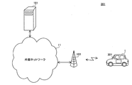
- FIG. 1 is a diagram showing a configuration of a communication system according to an embodiment of the present invention.
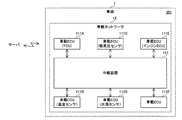
- FIG. 2 is a diagram showing the configuration of the in-vehicle communication system according to the embodiment of the present invention.
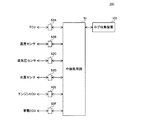
- FIG. 3 is a diagram showing the configuration of a relay device in the on-vehicle communication system according to the embodiment of the present invention.
- FIG. 4 is a diagram showing a configuration of a log collection device in the in-vehicle communication system according to the embodiment of the present invention.
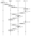
- FIG. 5 is a diagram showing an example of a sequence when the relay device receives the log notification information in the communication system according to the embodiment of the present invention.
- FIG. 6 is a diagram showing an example of a sequence when the relay device receives the log notification information in the communication system according to the embodiment of the present invention.
- FIG. 7 is a diagram showing an example of aggregated log information collected in the communication system according to the embodiment of the present invention.
- FIG. 8 is a diagram showing an example of a sequence when the relay device receives the log notification information in the communication system according to the embodiment of the present invention.
- FIG. 9 is a diagram showing an example of a sequence when the relay device receives the log notification information in the communication system according to the embodiment of the present invention.
- FIG. 10 is a diagram showing an example of a sequence when the temperature sensor receives the start condition information in the in-vehicle communication system according to the embodiment of the present invention.
- FIG. 11 is a diagram showing an example of aggregated log information collected in the communication system according to the embodiment of the present invention.
- FIG. 12 is a diagram showing an example of a sequence when the relay device receives the log notification information in the communication system according to the embodiment of the present invention.
- FIG. 13 is a diagram showing an example of a sequence when the relay device receives the log notification information in the communication system according to the embodiment of the present invention.
- FIG. 14 is a diagram showing an example of a sequence when the relay device receives the log notification information in the communication system according to the embodiment of the present invention.
- FIG. 15 is a diagram showing an example of aggregated log information collected in the communication system according to the embodiment of the present invention.
- in-vehicle network systems have been developed to improve security in in-vehicle networks.
- the in-vehicle control device in the in-vehicle network described in Patent Document 1 performs, for example, measurement of the environment and state of the vehicle, and control of components constituting the vehicle.
- the measurement results and control results by the on-vehicle controller are preferably recorded as a log because they are useful in the development of a vehicle and the like. However, if all information is recorded as a log, the amount of data becomes enormous. Technology is required to collect logs efficiently.
- the present disclosure has been made to solve the above-described problems, and an object thereof is to provide an on-vehicle communication device capable of efficiently collecting logs in an on-vehicle network, a log collection method, and a log collection program. It is.
- logs can be efficiently collected in an in-vehicle network.
- An on-vehicle communication device is an on-vehicle communication device capable of relaying data between a plurality of functional units mounted on a vehicle, and collecting logs from an external device outside the vehicle
- a log notification acquisition unit that receives a log notification indicating a log target function unit that is the target of the function, a start condition of log collection and a trigger function unit that is the function unit that can determine the start condition;
- a notification unit for notifying the trigger function unit of the start condition indicated by a), and an instruction unit for giving a log collection instruction to the log target function unit in response to a notification that the start condition is satisfied from the trigger function unit; Equipped with
- log collection limited to useful logs can be performed, for example, by appropriately setting log notifications for collecting logs useful for vehicle development in an external device.
- Logs can be collected efficiently.
- the measurement results of the environment and the state of the vehicle, and the learning contents of the control results of the parts constituting the vehicle can be utilized for vehicle development.
- the log notification indicates a plurality of the start conditions corresponding to one of the trigger function units.
- logs classified by vehicle state or vehicle environment can be efficiently collected.
- the log notification indicates a combination of a plurality of trigger functions and a plurality of start conditions respectively corresponding to the plurality of trigger functions
- the instruction unit indicates the plurality of start conditions Gives the instructions when all are satisfied.
- Such a configuration enables, for example, pinpoint collection of logs in a specific vehicle condition and a specific vehicle environment required for vehicle development.
- the log notification indicates a plurality of the sets
- the instruction unit indicates that the start condition is satisfied in any one of the plurality of sets. Give the instructions.
- logs classified into specific vehicle conditions and specific vehicle environments required for vehicle development can be efficiently collected.
- a log collection method is a log collection method in an on-vehicle communication device capable of relaying data between a plurality of functional units mounted on a vehicle, the external device outside the vehicle From the step of receiving a log notification indicating a log target function unit that is the target of log collection, a log collection start condition, and a trigger function unit that is the function unit that can determine the start condition; Notifying the trigger function unit of the start condition indicated by the notification; and giving a log collection instruction to the log function unit upon receiving notification from the trigger function unit that the start condition is satisfied.
- log collection limited to useful logs can be performed, for example, by appropriately setting log notifications for collecting logs useful for vehicle development in an external device.
- Logs can be collected efficiently.
- the measurement results of the environment and the state of the vehicle, and the learning contents of the control results of the parts constituting the vehicle can be utilized for vehicle development.
- a log collection program is a log collection program used in an on-vehicle communication device capable of relaying data between a plurality of functional units mounted on a vehicle, the computer comprising: Receive from the external device in the outside a log notification indicating a log target function unit that is the target of the log collection, a start condition of the log collection, and a trigger function unit that is the function unit that can determine the start condition; A log notification acquisition unit, a notification unit for notifying the trigger function unit of the start condition indicated by the log notification, and a notification indicating that the start condition is satisfied from the trigger function unit are instructed to collect logs. It is a program for functioning as an instruction unit to be given to the log target function unit.
- log collection limited to useful logs can be performed, for example, by appropriately setting log notifications for collecting logs useful for vehicle development in an external device.
- Logs can be collected efficiently.
- the measurement results of the environment and the state of the vehicle, and the learning contents of the control results of the parts constituting the vehicle can be utilized for vehicle development.
- FIG. 1 is a diagram showing a configuration of a communication system according to an embodiment of the present invention.
- the communication system 201 includes a server 181 and an in-vehicle communication system 301.
- the in-vehicle communication system 301 is mounted on the vehicle 1.
- the communication system 201 is not limited to a configuration including one set of the vehicle 1 and the in-vehicle communication system 301, and may have a configuration including a plurality of sets of the vehicle 1 and the in-vehicle communication system 301.
- FIG. 2 is a diagram showing the configuration of the in-vehicle communication system according to the embodiment of the present invention.
- in-vehicle communication system 301 includes in-vehicle ECUs (Electronic Control Units) 111A to 111F and a relay device (in-vehicle communication device) 151.
- in-vehicle ECUs Electronic Control Units
- relay device in-vehicle communication device
- each of the onboard ECUs 111A to 111F is also referred to as an onboard ECU 111.
- the on-board ECU 111 is an example of a functional unit.
- the on-vehicle communication system 301 is not limited to the configuration including the six on-vehicle ECUs 111, and may be configured to include two, three, four, five, or seven or more on-vehicle ECUs 111. Further, the on-vehicle communication system 301 is not limited to the configuration including one relay device 151, and may have a configuration including a plurality of relay devices 151.
- the on-vehicle ECU 111 is, for example, a TCU (Telematics Communication Unit), an automatic operation ECU (Electronic Control Unit), an engine ECU, a sensor, a navigation device, a human machine interface, a camera, and the like.
- TCU Transmission Control Unit
- ECU Electronic Control Unit
- engine ECU a sensor
- navigation device a human machine interface
- camera and the like.
- the on-board ECUs 111A, 111B, 111C, 111D, and 111E are a TCU, a temperature sensor, an intake pressure sensor, a water temperature sensor, and an engine ECU, respectively.
- on-vehicle ECUs 111A, 111B, 111C, 111D, and 111E are also referred to as TCU 111A, temperature sensor 111B, intake pressure sensor 111C, water temperature sensor 111D, and engine ECU 111E, respectively.
- the in-vehicle ECUs 111A to 111F are connected to the relay device 151 via an Ethernet (registered trademark) cable.
- the relay device 151 is, for example, a gateway device, and can relay data between a plurality of functional units mounted on the vehicle 1.
- the relay apparatus 151 relays an Ethernet frame according to the Ethernet communication standard.
- relay device 151 relays, for example, an Ethernet frame exchanged between onboard ECUs 111.
- An IP packet is stored in the Ethernet frame.
- the on-vehicle communication system 301 is not limited to the configuration in which the Ethernet frame is relayed according to the Ethernet communication standard, for example, CAN (Controller Area Network) (registered trademark), FlexRay (registered trademark), or MOST (Media Oriented Systems Transport) Data relay may be performed according to a communication standard such as (registered trademark) and LIN (Local Interconnect Network).
- CAN Controller Area Network
- FlexRay registered trademark
- MOST Media Oriented Systems Transport
- LIN Local Interconnect Network
- the temperature sensor 111 ⁇ / b> B can communicate with another in-vehicle ECU 111 via the relay device 151 and, for example, periodically measures the outside air temperature of the vehicle 1.
- the intake pressure sensor 111 ⁇ / b> C can communicate with another on-vehicle ECU 111 via the relay device 151 and, for example, periodically measures an intake pressure of an engine in the vehicle 1.
- the water temperature sensor 111D can communicate with another in-vehicle ECU 111 via the relay device 151, and periodically measures, for example, the temperature of the cooling water circulating in the engine of the vehicle 1.
- the engine ECU 111E can communicate with another in-vehicle ECU 111 via the relay device 151, and controls an engine in the vehicle 1, for example.
- the engine ECU 111E acquires and acquires information indicating, for example, the number of revolutions of the engine, the speed of the vehicle 1, the shaft torque of the engine, the state of the transmission, the state of the throttle valve, and the measurement values of the respective sensors. Control the engine based on the selected information.
- engine ECU 111E can transmit part or all of the acquired information to relay device 151, for example, in response to a request from relay device 151.
- TCU 111A can communicate with server 181.
- the TCU 111A can communicate with the server 181 via the radio base station apparatus 161, for example, in accordance with the IP protocol.
- the TCU 111A can perform wireless communication with the wireless base station device 161, for example, in accordance with a communication standard such as Long Term Evolution (LTE) or 3G.
- LTE Long Term Evolution
- 3G 3th Generation
- the TCU 111A when the TCU 111A receives, for example, a wireless frame in which an IP packet from the server 181 is stored from the wireless base station device 161, the TCU 111A acquires an IP packet from the received wireless frame, and acquires the acquired IP packet as an Ethernet frame. And transmit to the relay apparatus 151.
- the TCU 111 A when the TCU 111 A receives an Ethernet frame from the relay device 151, the TCU 111 A acquires an IP packet from the received Ethernet frame, stores the acquired IP packet in a wireless frame, and transmits the wireless frame to the wireless base station device 161.
- the wireless base station device 161 When the wireless base station device 161 receives a wireless frame from the TCU 111A, the wireless base station device 161 acquires an IP packet from the received wireless frame, and transmits the acquired IP packet to the server 181 via the external network 11.
- the wireless base station device 161 upon receiving an IP packet from the server 181 via the external network 11, stores the received IP packet in a wireless frame, and transmits the wireless frame to the TCU 111A.
- FIG. 3 is a diagram showing the configuration of a relay device in the on-vehicle communication system according to the embodiment of the present invention.
- relay device 151 includes relay processing unit 51, communication ports 52A, 52B, 52C, 52D, 52E, 52F, and log collection device 101.
- each of communication ports 52A, 52B, 52C, 52D, 52E, 52F is also referred to as communication port 52.
- the communication port 52 is, for example, a terminal to which an Ethernet cable can be connected.
- the communication ports 52A, 52B, 52C, 52D, 52E, 52F are respectively connected to the TCU 111A, the temperature sensor 111B, the intake pressure sensor 111C, the water temperature sensor 111D, the engine ECU 111E, and the onboard ECU 111F.
- the relay processing unit 51 relays Ethernet frames. Specifically, when receiving an Ethernet frame via the communication port 52, for example, the relay processing unit 51 performs layer 2 switch processing and layer 3 relay processing on the received Ethernet frame.
- the relay processing unit 51 transmits the Ethernet frame after switch processing or relay processing via the other communication port 52.
- FIG. 4 is a diagram showing a configuration of a log collection device in the in-vehicle communication system according to the embodiment of the present invention.
- the log collection device 101 includes an acquisition unit 21, a notification unit 22, a storage unit 23, and a processing unit (instruction unit) 24.
- Each device in the communication system 201 includes a computer, and an arithmetic processing unit such as a CPU in the computer reads and executes a program including part or all of each step of the following sequence diagram or flowchart from a memory (not shown).
- the programs of the plurality of devices can be installed from the outside.
- the programs of the plurality of apparatuses are distributed as stored in the recording medium.
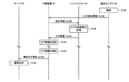
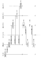
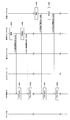
- FIG. 5 and 6 are diagrams showing an example of a sequence when the relay device receives the log notification information in the communication system according to the embodiment of the present invention.
- FIG. 6 is a continuation of the sequence of FIG.
- the administrator corresponds to the correspondence relationship between the engine rotational speed and the shaft torque when the outside air temperature in the vehicle 1 is 5 ° C., 10 ° and 15 ° C.
- An instruction for collecting logs is input to the server 181 (step S102).
- the server 181 receives the input from the administrator, creates log notification information corresponding to the log notification, and transmits the created log notification information to the relay device 151 of the vehicle 1 (step S104).
- the server 181 manages, for example, the configuration of the in-vehicle network 12 in the vehicle 1, and creates log notification information based on the management content and the input content from the manager.
- the log notification information includes the type of log target information, the log target functional unit that is a functional unit that is the target of log collection, the start condition of the log collection, and the trigger function that is a functional unit that can determine the start condition. Indicates a part.
- the log notification information indicates, for example, a plurality of start conditions corresponding to one trigger function unit.
- the log notification information includes, for example, the engine speed and shaft torque as the type of information to be logged, the address of the engine ECU 111E as the function unit to be logged (hereinafter also referred to as a log address), and 5 as the start condition.
- the outside air temperatures of 10 ° C., 10 ° C., and 15 ° C., and the address of the temperature sensor 111 B (hereinafter also referred to as a first trigger address) as a trigger function portion are shown.
- the log address and the first trigger address are, for example, IP (Internet Protocol) addresses.
- the log address and the first trigger address may be MAC (Media Access Control) addresses.
- the port number of the communication port 52 to which the log target function unit is connected in the relay apparatus 151 may be used.
- the port number of the communication port 52 to which the trigger function unit is connected in the relay apparatus 151 may be used.
- the relay device 151 when receiving the log notification information from the server 181, the relay device 151 creates start condition information and instruction information based on the received log notification information (step S106).
- the relay processing unit 51 in the relay device 151 when receiving the log notification information from the server 181 via the TCU 111A, the relay processing unit 51 in the relay device 151 outputs the received log notification information to the log collection device 101.
- the acquisition unit 21 in the log collection device 101 receives log notification information from an external device outside the vehicle 1, here, the server 181.
- the acquisition unit 21 when receiving the log notification information from the relay processing unit 51, the acquisition unit 21 outputs the received log notification information to the processing unit 24.
- the processing unit 24 determines from the received log notification information the engine speed and shaft torque as the type of information to be logged, the log address, the start condition, and the first trigger address.
- the first trigger address obtained is taken as a destination, and start condition information including external temperatures of 5 ° C., 10 ° C. and 15 ° C. as start conditions is created.
- processing unit 24 creates instruction information including the acquired log address as a destination and including the engine rotational speed and shaft torque as the type of information to be logged.
- the relay device 151 transmits the created start condition information to the temperature sensor 111B (step S108).
- the processing unit 24 in the log collection device 101 outputs the created start condition information to the notification unit 22.
- the notification unit 22 notifies the trigger function unit of the start condition indicated by the log notification information. Specifically, upon receiving the start condition information from the processing unit 24, the notification unit 22 outputs the received start condition information to the relay processing unit 51.
- the relay processing unit 51 When receiving the start condition information from the notification unit 22, the relay processing unit 51 transmits the start condition information to the temperature sensor 111B via the communication port 52B using the first trigger address that is the destination of the received start condition information. .
- the temperature sensor 111B sets the start conditions included in the received start condition information, that is, the outside temperatures of 5 ° C., 10 ° C. and 15 ° C. as the trigger conditions (step S110). ).
- the temperature sensor 111B detects that the trigger condition of 5 ° C. is satisfied, for example, by measuring the outside air temperature of 5 ° C. (step S112).
- the temperature sensor 111B transmits trigger detection information indicating that the trigger condition of 5 ° C. is satisfied to the relay device 151 (step S114).
- the relay device 151 when receiving the trigger detection information from the temperature sensor 111B, the relay device 151 transmits instruction information to the engine ECU 111E (step S116).
- the relay processing unit 51 in the relay device 151 when receiving the trigger detection information from the temperature sensor 111 B, the relay processing unit 51 in the relay device 151 outputs the received trigger detection information to the log collection device 101.
- the acquisition unit 21 in the log collecting apparatus 101 When receiving the trigger detection information from the relay processing unit 51, the acquisition unit 21 in the log collecting apparatus 101 outputs the received trigger detection information to the processing unit 24.
- the processing unit 24 In response to the notification that the start condition is satisfied from the trigger function unit, the processing unit 24 gives a log collection instruction to the log target function unit.
- the processing unit 24 when receiving the trigger detection information from the acquisition unit 21, the processing unit 24 recognizes that the outside temperature of 5 ° C. is measured by the temperature sensor 111B based on the received trigger detection information, and generates The stored instruction information is output to the relay processing unit 51.
- the relay processing unit 51 When receiving the instruction information from the processing unit 24, the relay processing unit 51 transmits the instruction information to the engine ECU 111E via the communication port 52E using the log address which is the destination of the received instruction information.
- step S118 when the engine ECU 111E receives the instruction information from the relay device 151, the engine ECU 111E acquires log target information included in the instruction information according to the received instruction information (step S118).
- the engine ECU 111E acquires information indicating the engine rotational speed and information indicating the shaft torque for one point.
- the engine ECU 111E transmits log information including the acquired pieces of information to the relay device 151 (step S120).
- the relay device 151 stores the received log information (step S122).
- the relay processing unit 51 in the relay device 151 when receiving the log information from the engine ECU 111E, the relay processing unit 51 in the relay device 151 outputs the received log information to the log collection device 101.
- the acquisition unit 21 in the log collection device 101 When receiving the log information from the relay processing unit 51, the acquisition unit 21 in the log collection device 101 outputs the received log information to the processing unit 24.
- the processing unit 24 When the processing unit 24 receives the log information from the acquisition unit 21, the processing unit 24 includes 5 ° C. included in the trigger detection information in the received log information. Then, the processing unit 24 stores the log information in the storage unit 23.
- the operation of the steps S112 to S122 is repeated, for example, every time the 5 ° C. trigger condition is satisfied in the temperature sensor 111B.
- the temperature sensor 111B detects that the trigger condition of 10 ° C. is satisfied, for example, by measuring the outside air temperature of 10 ° C. (step S124).
- the temperature sensor 111B transmits trigger detection information indicating that the trigger condition of 10 ° C. is satisfied to the relay device 151 (step S126).
- the relay device 151 transmits instruction information to the engine ECU 111E (step S128).
- the processing unit 24 in the relay device 151 receives trigger detection information from the temperature sensor 111 B via the relay processing unit 51 and the acquisition unit 21, the temperature sensor 111 B measures 10 ° C. based on the received trigger detection information. Recognizes that the outside air temperature has been measured, and transmits the generated instruction information to the engine ECU 111E via the relay processing unit 51.
- the engine ECU 111E when the engine ECU 111E receives the instruction information from the relay device 151, the engine ECU 111E follows the received instruction information, and outputs one point each of the information to be logged included in the instruction information, that is, the information indicating the engine rotational speed and the information indicating the shaft torque. A minute is acquired (step S130).
- the engine ECU 111E transmits log information including the acquired pieces of information to the relay device 151 (step S132).
- the relay device 151 when receiving the log information from the engine ECU 111E, the relay device 151 saves the received log information (step S134).
- the processing unit 24 in the relay device 151 when receiving the log information from the engine ECU 111E via the relay processing unit 51 and the acquisition unit 21, the processing unit 24 in the relay device 151 includes 10 ° C. included in the trigger detection information in the received log information. Then, the processing unit 24 stores the log information in the storage unit 23.
- the temperature sensor 111B detects that the trigger condition of 15 ° C. is satisfied, for example, by measuring the outside air temperature of 15 ° C. (step S136).
- the temperature sensor 111B transmits trigger detection information indicating that the trigger condition of 15 ° C. is satisfied to the relay device 151 (step S138).
- the relay device 151 transmits instruction information to the engine ECU 111E (step S140).
- the processing unit 24 in the relay device 151 receives trigger detection information from the temperature sensor 111 B via the relay processing unit 51 and the acquisition unit 21, the temperature sensor 111 B measures 15 ° C. based on the received trigger detection information. Recognizes that the outside air temperature has been measured, and transmits the generated instruction information to the engine ECU 111E via the relay processing unit 51.
- the engine ECU 111E when the engine ECU 111E receives the instruction information from the relay device 151, the engine ECU 111E follows the received instruction information, and outputs one point each of the information to be logged included in the instruction information, that is, the information indicating the engine rotation speed and the information A minute is acquired (step S142).
- the engine ECU 111E transmits log information including the acquired pieces of information to the relay device 151 (step S144).
- the relay device 151 stores the received log information (step S146).
- the processing unit 24 in the relay apparatus 151 when receiving the log information from the engine ECU 111E via the relay processing unit 51 and the acquisition unit 21, the processing unit 24 in the relay apparatus 151 includes 15 ° C. included in the trigger detection information in the received log information. Then, the processing unit 24 stores the log information in the storage unit 23.
- the operation of the steps S136 to S146 is repeated, for example, every time the trigger condition of 15 ° C. is satisfied in the temperature sensor 111B.
- the relay device 151 creates aggregated log information by aggregating the stored log information (step S148).
- the processing unit 24 in the relay device 151 aggregates log information by aggregating each log information stored in the storage unit 23.
- the processing unit 24 transmits the created aggregated log information to the server 181 via the relay processing unit 51 and the TCU 111A (step S150).
- step S152 when the server 181 receives the aggregated log information from the relay device 151, the server 181 performs an accumulation process of accumulating the received aggregated log information.
- the start condition is that the outside air temperature is a specific value, but the invention is not limited to this.
- the start condition may be that the outside air temperature has a value within a specific range.
- the order of the steps S112 to S122, the steps S124 to S134, and the steps S136 to S146 is not limited to the above, and some or all of the orders may be changed.
- the engine ECU 111E is configured to acquire information indicating the engine rotational speed and information indicating the shaft torque for one point, but the present invention is not limited to this.
- the engine ECU 111E may be configured to acquire information of a plurality of points indicating the engine rotational speed and information of a plurality of points indicating the shaft torque in a predetermined period.
- the relay apparatus 151 receives and stores log information from the engine ECU 111E.
- the engine ECU 111E stores log information, and when the log information for a predetermined number of points is stored in the engine ECU 111E, the relay device 151 collectively acquires the log information stored in the engine ECU 111E. It may be.
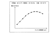
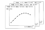
- FIG. 7 is a diagram showing an example of aggregated log information collected in the communication system according to the embodiment of the present invention.
- the horizontal axis represents the engine speed
- the vertical axis represents the shaft torque.
- the server 181 stores aggregate log information including the correspondence between the engine rotation speed and the shaft torque at an external temperature of 5 ° C., 10 ° C. and 15 ° C. requested by the administrator. .
- the aggregated log information accumulated in the server 181 is fed back, for example, to the manufacturer of the vehicle 1.
- the manufacturer of the vehicle 1 plots traveling performance curves at outside temperatures of 5 ° C., 10 ° C., and 15 ° C., respectively, on graphs, using aggregated log information, for example.
- the manufacturer of the vehicle 1 can acquire the traveling performance curve of the engine for each environmental condition, so that, for example, the setting value in the control program of the engine, etc. Can be adjusted appropriately.
- the log notification information is configured to indicate a plurality of start conditions corresponding to one trigger function unit, the present invention is not limited to this.
- the log notification information may indicate, for example, a plurality of trigger function units and a plurality of sets of start conditions respectively corresponding to the plurality of trigger function units.
- the processing unit 24 in the log collection apparatus 101 gives an instruction of log collection, for example, when all the plurality of start conditions are satisfied.
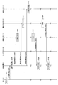
- FIGS. 8 and 9 are diagrams showing an example of a sequence when the relay device receives the log notification information in the communication system according to the embodiment of the present invention.
- FIG. 9 is a continuation of the sequence of FIG.
- the administrator can set the outside temperature in the vehicle 1 to 9 ° C. to 11 ° C., the intake pressure to 45 kPa to 55 kPa, and the water temperature to 45 ° C. to 55
- a command for causing the vehicle 1 to collect a log is input to the server 181 (step S202).
- the server 181 receives the input from the administrator, creates log notification information, and transmits the created log notification information to the relay device 151 of the vehicle 1 (step S204).
- the log notification information includes, for example, the engine rotational speed and shaft torque as the type of information to be logged, the address of the engine ECU 111E as the log target functional unit, that is, the address for log, and the addresses of multiple trigger functional units 6 shows start conditions respectively corresponding to the addresses of the plurality of trigger function units.
- the addresses of the plurality of trigger function units are, for example, the address of the temperature sensor 111B, that is, the address for the first trigger, the address for the intake pressure sensor 111C (hereinafter also referred to as the address for the second trigger), and the water temperature sensor 111D. This is an address (hereinafter also referred to as a third trigger address).
- the start conditions corresponding to the first trigger address, the second trigger address, and the third trigger address are an external temperature of 9 ° C. to 11 ° C., an intake pressure of 45 kPa to 55 kPa, and a water temperature of 45 ° C. to 55 ° C. .
- the relay device 151 when receiving the log notification information from the server 181, the relay device 151 creates start condition information and instruction information based on the received log notification information (step S206).
- the processing unit 24 in the relay device 151 acquires the following information from the received log notification information.
- the processing unit 24 determines the engine speed and shaft torque as the type of information to be logged, the log address, the first trigger address, the second trigger address and the third trigger address, and the first trigger.
- the outside air temperature is 9 ° C to 11 ° C
- the intake pressure is 45kPa to 55kPa
- the water temperature is 45 ° C to 55 ° C as start conditions respectively corresponding to the address for the second trigger and the address for the second trigger .
- the processing unit 24 creates start condition information SC1 having the acquired first trigger address as a destination and including an outside temperature of 9 ° C. to 11 ° C. as a start condition.
- the processing unit 24 creates start condition information SC2 including the acquired second trigger address as a destination and including an intake pressure of 45 kPa to 55 kPa as a start condition.
- the processing unit 24 creates start condition information SC3 having the acquired third trigger address as a destination and containing a water temperature of 45 ° C. to 55 ° C. as a start condition.
- processing unit 24 creates instruction information including the acquired log address as a destination and including the engine rotational speed and shaft torque as the type of information to be logged.
- the relay device 151 transmits the created start condition information SC1 to the temperature sensor 111B (step S208).
- the processing unit 24 in the relay device 151 transmits the created start condition information SC1 to the temperature sensor 111B via the notification unit 22 and the relay processing unit 51.
- the temperature sensor 111B sets the start condition included in the received start condition information SC1, that is, the outside temperature of 9 ° C. to 11 ° C. as the trigger condition (step S210). .
- the relay device 151 transmits the created start condition information SC2 to the intake pressure sensor 111C (step S212).
- the processing unit 24 in the relay device 151 transmits the created start condition information SC2 to the intake pressure sensor 111C via the notification unit 22 and the relay processing unit 51.
- the intake pressure sensor 111C when the intake pressure sensor 111C receives the start condition information SC2 from the relay apparatus 151, the intake pressure sensor 111C sets the start condition included in the received start condition information SC2, ie, the intake pressure of 45 kPa to 55 kPa as a trigger condition (step S214).
- the relay device 151 transmits the created start condition information SC3 to the water temperature sensor 111D (step S216).
- the processing unit 24 in the relay device 151 transmits the created start condition information SC3 to the water temperature sensor 111D via the notification unit 22 and the relay processing unit 51.
- the water temperature sensor 111D when the water temperature sensor 111D receives the start condition information SC3 from the relay device 151, the water temperature sensor 111D sets the start condition included in the received start condition information SC3, ie, the water temperature of 45 ° C. to 55 ° C. as the trigger condition (step S218).
- temperature sensor 111 B detects that the trigger condition of 9 ° C. to 11 ° C. is satisfied, for example, by measuring the outside air temperature contained in 9 ° C. to 11 ° C. (step S 220).
- the temperature sensor 111B transmits trigger detection information TD1 indicating that the trigger condition of 9 ° C. to 11 ° C. is satisfied to the relay device 151 (step S222).
- the relay device 151 turns on the corresponding flag based on the received trigger detection information TD1 (step S224).
- the processing unit 24 in the relay device 151 receives the trigger detection information TD1 from the temperature sensor 111B via the relay processing unit 51 and the acquisition unit 21, the processing unit 24 in the temperature sensor 111B based on the received trigger detection information TD1. Recognize that the outside air temperature contained in 9 ° C-11 ° C was measured.
- the processing unit 24 turns on a flag F1 indicating that, for example, the outside air temperature contained in 9 ° C. to 11 ° C. has been measured by the temperature sensor 111B.
- the flag F1 is turned off, for example, when a predetermined survival period elapses after being turned on.
- the predetermined survival period is set, for example, in accordance with the degree of change in the outside air temperature.
- the operation of the above steps S220 to S224 is repeated, for example, every time the trigger condition of 9 ° C. to 11 ° C. is satisfied in the temperature sensor 111B.
- the intake pressure sensor 111C detects that the trigger condition of 45 kPa to 55 kPa is satisfied, for example, by measuring the intake pressure included in 45 kPa to 55 kPa (step S226).
- the intake pressure sensor 111C transmits trigger detection information TD2 indicating that the trigger condition of 45 kPa to 55 kPa is satisfied to the relay apparatus 151 (step S228).
- the relay device 151 turns on the corresponding flag based on the received trigger detection information TD2 (step S230).
- the processing unit 24 in the relay device 151 detects the intake pressure sensor based on the received trigger detection information TD2. It is recognized that the intake pressure included in 45 kPa to 55 kPa was measured at 111C.
- the processing unit 24 turns on a flag F2 indicating that, for example, the intake pressure included in 45 kPa to 55 kPa has been measured by the intake pressure sensor 111C.
- the flag F2 is turned off, for example, when the predetermined survival period elapses after being turned on.
- the predetermined survival period is set, for example, according to the degree of change in the inspiratory pressure.
- the operation of the steps S226 to S230 is repeated, for example, every time the trigger condition of 45 kPa to 55 kPa is satisfied in the intake pressure sensor 111C.
- the water temperature sensor 111D detects that the trigger condition of 45 ° C. to 55 ° C. is satisfied, for example, by measuring the water temperature contained in 45 ° C. to 55 ° C. (step S232).
- the water temperature sensor 111D transmits trigger detection information TD3 indicating that the trigger condition of 45 ° C. to 55 ° C. is satisfied to the relay apparatus 151 (step S234).
- the relay device 151 when the relay device 151 receives the trigger detection information TD3 from the water temperature sensor 111D, the relay device 151 turns on the corresponding flag based on the received trigger detection information TD3 (step S236).
- the processing unit 24 in the relay device 151 receives the trigger detection information TD3 from the water temperature sensor 111D via the relay processing unit 51 and the acquisition unit 21, the processing unit 24 in the water temperature sensor 111D based on the received trigger detection information TD3. It recognizes that the water temperature contained in 45 ° C. to 55 ° C. has been measured.
- the processing unit 24 turns on a flag F3 indicating that the water temperature contained in 45 ° C. to 55 ° C. has been measured by the water temperature sensor 111D.
- the flag F3 is turned off, for example, when the predetermined survival period elapses after being turned on.
- the predetermined survival period is set, for example, in accordance with the degree of change in the water temperature.
- the operation of the above steps S232 to S236 is repeated, for example, every time the trigger condition of 45 ° C. to 55 ° C. is satisfied in the water temperature sensor 111D.
- the processing unit 24 in the relay device 151 transmits the generated instruction information to the engine ECU 111E via the relay processing unit 51 (step S238).
- step S240 when the engine ECU 111E receives the instruction information from the relay device 151, the engine ECU 111E follows the received instruction information, and outputs one point each of the information to be logged included in the instruction information, that is, the information indicating the engine rotational speed and the information indicating the shaft torque. A minute is acquired (step S240).
- the engine ECU 111E transmits log information including the acquired pieces of information to the relay device 151 (step S242).
- the relay device 151 stores the received log information (step S244).
- the processing unit 24 in the relay device 151 receives log information from the engine ECU 111 E via the relay processing unit 51 and the acquisition unit 21, the start condition, that is, the outside air temperature is 9 ° C. to 11 ° C. in the received log information. , Including an intake pressure of 45 kPa to 55 kPa and a water temperature of 45 ° C. to 55 ° C. Then, the processing unit 24 stores the log information in the storage unit 23.
- the relay device 151 creates aggregated log information by aggregating the stored log information (step S246).
- the processing unit 24 in the relay device 151 aggregates log information by aggregating each log information stored in the storage unit 23.
- the processing unit 24 transmits the created aggregated log information to the server 181 via the relay processing unit 51 (step S248).
- step S250 when the server 181 receives the aggregation log information from the relay device 151, the server 181 performs an accumulation process of accumulating the received aggregation log information.
- start condition is that the outside air temperature, the intake pressure, and the water temperature become values within a specific range
- present invention is not limited to this.
- the start condition may be that the outside air temperature, the intake pressure, and the water temperature become specific values.
- steps S208 and S210, the steps S212 and S214, and the steps S216 and S218 is not limited to the above, and some or all of the orders may be changed.
- the order of the steps S220 to S224, the steps S226 to S230, and the steps S232 to S236 is not limited to the above, and some or all of the orders may be changed.
- the flags F1 to F3 are automatically turned off when the corresponding survival period elapses after being turned on.
- the flags F1 to F3 may be turned on while the corresponding trigger condition is satisfied, and turned off when the corresponding trigger condition is not satisfied.
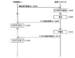
- FIG. 10 is a diagram showing an example of a sequence when the temperature sensor receives the start condition information in the in-vehicle communication system according to the embodiment of the present invention.
- relay device 151 transmits start condition information SC1 to temperature sensor 111B (step S302).
- the temperature sensor 111B sets the start condition included in the received start condition information SC1, that is, the outside temperature of 9 ° C. to 11 ° C. as the trigger condition (step S304). .
- temperature sensor 111 B detects that the trigger condition of 9 ° C. to 11 ° C. is satisfied, for example, by measuring the outside air temperature contained in 9 ° C. to 11 ° C. (step S 306).
- the temperature sensor 111B transmits trigger detection information TD1 indicating that the trigger condition of 9 ° C. to 11 ° C. is satisfied to the relay device 151 (step S308).
- the relay device 151 when receiving the trigger detection information TD1 from the temperature sensor 111B, the relay device 151 turns on the flag F1 based on the received trigger detection information TD1 (step S310). In this example, the predetermined survival period is not set in the flag F1.
- the temperature sensor 111 B does not detect that the trigger condition of 9 ° C. to 11 ° C. is satisfied, for example, by measuring the outside air temperature other than 9 ° C. to 11 ° C. (step S 312).
- the temperature sensor 111 B transmits trigger non-detection information ND 1 indicating that the trigger condition of 9 ° C. to 11 ° C. is not satisfied to the relay device 151 (step S 314).
- the relay device 151 when the relay device 151 receives the trigger non-detection information ND1 from the temperature sensor 111B, the relay device 151 turns off the flag F1 based on the received trigger non-detection information ND1 (step S316).
- the trigger detection information TD2 is also transmitted to the relay apparatus 151 (step S306).
- step S308 Further, when it is not detected that the trigger condition of 45 kPa to 55 kPa is satisfied (step S312), trigger non-detection information ND2 is transmitted to the relay apparatus 151 (step S314).
- the relay device 151 when the relay device 151 receives the trigger detection information TD2 from the intake pressure sensor 111C, it turns on the flag F2 (step S310), and when it receives the trigger non-detection information ND2 from the intake pressure sensor 111C, the flag F2 It turns off (step S316).
- trigger detection information TD 3 is transmitted to the relay apparatus 151 (step S 308).
- trigger non-detection information ND3 is transmitted to the relay apparatus 151 (step S314).
- the relay device 151 when receiving the trigger detection information TD3 from the water temperature sensor 111D, the relay device 151 turns on the flag F3 (step S310), and turns off the flag F3 when receiving the trigger non-detection information ND3 from the water temperature sensor 111D. (Step S316).
- FIG. 11 is a diagram showing an example of aggregated log information collected in the communication system according to the embodiment of the present invention. Note that the view of FIG. 11 is the same as that of FIG.
- the server 181 is requested by the administrator to have an engine speed and a shaft torque at an outside air temperature of 9 ° C. to 11 ° C., an intake pressure of 45 kPa to 55 kPa, and a water temperature of 45 ° C. to 55 ° C. Aggregated log information including the correspondence of is accumulated.
- the log notification information is configured to indicate a plurality of start conditions corresponding to one trigger function unit, the present invention is not limited to this.
- the log notification information may indicate, for example, a plurality of trigger function units and a plurality of sets of start conditions respectively corresponding to the plurality of trigger function units.
- the processing unit 24 in the log collection device 101 gives an instruction of log collection, for example, when all the plurality of start conditions are satisfied in any one of the plurality of sets.
- FIG. 12 is a continuation of the sequence of FIG.
- FIG. 14 is a continuation of the sequence of FIG.
- the administrator corresponds the correspondence relationship between the engine speed and the shaft torque in the following states ST1, ST2 and ST3 in vehicle 1
- An instruction for collecting logs in the vehicle 1 is input to the server 181 (step S402).
- the outside air temperature is 39 ° C. to 41 ° C.
- the intake pressure is 45 kPa to 55 kPa
- the water temperature is 45 ° C. to 55 ° C.
- the outside air temperature is 19 ° C. to 21 ° C.
- the intake pressure is 81 kPa to 99 kPa
- the water temperature is 20 ° C. to 30 ° C.
- the outside air temperature is ⁇ 1 ° C. to 1 ° C.
- the intake pressure is 9 kPa to 11 kPa
- the water temperature is 0 ° C. to 10 ° C.
- the server 181 receives the input from the administrator, creates log notification information, and transmits the created log notification information to the relay device 151 of the vehicle 1 (step S404).
- the log notification information includes, for example, the engine speed and shaft torque as the type of information to be logged, the address of the engine ECU 111E as the log target functional unit, that is, the address for logging, and the pairs CL1, CL2, and CL3. Show.
- each of the sets CL1, CL2, and CL3 includes the addresses of the plurality of trigger function units and the start conditions respectively corresponding to the addresses of the plurality of trigger function units.
- the sets CL1, CL2, and CL3 are created based on the states ST1, ST2, and ST3, respectively.
- the addresses of the plurality of trigger function units in each of the sets CL1, CL2, and CL3 are the address of the temperature sensor 111B, that is, the first trigger address, the address of the intake pressure sensor 111C, that is, the second trigger address, and the water temperature.
- the address of the sensor 111D that is, the address for the third trigger.
- the start conditions respectively corresponding to the first trigger address, the second trigger address, and the third trigger address included in the group CL1 are an outside temperature of 39 ° C. to 41 ° C., an intake pressure of 45 kPa to 55 kPa, and a water temperature of 45 ° C to 55 ° C.
- the start conditions respectively corresponding to the first trigger address, the second trigger address, and the third trigger address included in the group CL2 are an outside temperature of 19 ° C. to 21 ° C., an intake pressure of 81 kPa to 99 kPa, and a water temperature of 20 ° C to 30 ° C.
- the start conditions respectively corresponding to the first trigger address, the second trigger address, and the third trigger address included in the group CL3 are: outside temperature -1 ° C. to 1 ° C., intake pressure 9 kPa to 11 kPa and water temperature 0 ° C. to 10 ° C.
- the relay device 151 when receiving the log notification information from the server 181, the relay device 151 creates start condition information and instruction information based on the received log notification information (step S406).
- the processing unit 24 in the relay device 151 acquires the following information from the received log notification information.
- the processing unit 24 acquires the engine rotation speed and shaft torque as the type of information to be logged, the log address, and the sets CL1, CL2, and CL3.
- the processing unit 24 uses the first trigger address as the destination, and the outside air temperature of 39 ° C. to 41 ° C., the outside air temperature of 19 ° C. to 21 ° C., and Start condition information SC4 including the outside temperature of 1 ° C. to 1 ° C. is created.
- the processing unit 24 addresses the second trigger address as a destination based on the acquired sets CL1, CL2, and CL3 and has an intake pressure of 45 kPa to 55 kPa, an intake pressure of 81 kPa to 99 kPa, and 9 kPa to 55 kPa as start conditions.
- Start condition information SC5 including an intake pressure of 11 kPa is created.
- the processing unit 24 addresses the third trigger address as a destination based on the acquired sets CL1, CL2 and CL3, and has a water temperature of 45 ° C. to 55 ° C., a water temperature of 20 ° C. to 30 ° C., and a start condition.
- Start condition information SC6 including a water temperature of 0 ° C. to 10 ° C. is created.
- processing unit 24 creates instruction information including the acquired log address as a destination and including the engine rotational speed and shaft torque as the type of information to be logged.
- the relay device 151 transmits the created start condition information SC4 to the temperature sensor 111B (step S408).
- the processing unit 24 in the relay device 151 transmits the created start condition information SC4 to the temperature sensor 111B via the notification unit 22 and the relay processing unit 51.
- the temperature sensor 111B receives the start condition information SC4 from the relay apparatus 151, the start condition included in the received start condition information SC4, that is, the outside temperature of 39 ° C. to 41 ° C., the outside temperature of 19 ° C. to 21 ° C., And the outside temperature of -1 ° C. to 1 ° C. is set as the trigger conditions T41, T42 and T43, respectively (step S410).
- the relay device 151 transmits the created start condition information SC5 to the intake pressure sensor 111C (step S412).
- the processing unit 24 in the relay device 151 transmits the created start condition information SC5 to the intake pressure sensor 111C via the notification unit 22 and the relay processing unit 51.
- the intake pressure sensor 111C receives the start condition information SC5 from the relay device 151, the start condition included in the received start condition information SC5, that is, an intake pressure of 45 kPa to 55 kPa, an intake pressure of 81 kPa to 99 kPa, and 9 kPa to Intake pressures of 11 kPa are set as trigger conditions T51, T52 and T53, respectively (step S414).
- the relay device 151 transmits the created start condition information SC6 to the water temperature sensor 111D (step S416).
- the processing unit 24 in the relay device 151 transmits the created start condition information SC6 to the water temperature sensor 111D via the notification unit 22 and the relay processing unit 51.
- the water temperature sensor 111D receives the start condition information SC6 from the relay device 151, the water temperature sensor 111D receives the start conditions included in the received start condition information SC6, that is, the water temperature of 45 ° C. to 55 ° C., the water temperature of 20 ° C. to 30 ° C. Water temperatures of 10 ° C. to 10 ° C. are set as trigger conditions T61, T62 and T63, respectively (step S418).
- the temperature sensor 111B measures trigger conditions T41, T42, for example, by measuring the outside temperature included in any one of 39 ° C. to 41 ° C., 19 ° C. to 21 ° C., and -1 ° C. to 1 ° C. Alternatively, it is detected that T43 is satisfied (step S420).
- the temperature sensor 111B detects that the trigger condition T41, T42 or T43 is satisfied, the trigger condition of 39 ° C. to 41 ° C. is satisfied, and the trigger condition of 19 ° C. to 21 ° C.
- the trigger detection information TD4 indicating that the condition is satisfied or the trigger condition of -1.degree. C. to 1.degree. C. is satisfied is transmitted to the relay apparatus 151 (step S422).
- the relay device 151 when receiving the trigger detection information TD4 from the temperature sensor 111B, the relay device 151 turns on the corresponding flag based on the received trigger detection information TD4 (step S424).
- the processing unit 24 in the relay device 151 performs the following processing.
- the processing unit 24 indicates that the outside temperature included in the temperature range of 39 ° C. to 41 ° C. is measured by the temperature sensor 111B.
- the flag F41 is turned on.
- the processing unit 24 indicates that the outside temperature included in 19 ° C. to 21 ° C. is measured by the temperature sensor 111B.
- the flag F42 is turned on.
- the processing unit 24 measures the outside air temperature included in the temperature range of ⁇ 1 ° C. to 1 ° C. in the temperature sensor 111B. Flag F43 is turned on.
- the temperature sensor 111B measures trigger conditions T41, T42 and T43 by measuring the outside temperature not included in, for example, 39 ° C. to 41 ° C., 19 ° C. to 21 ° C. and -1 ° C. to 1 ° C. It will not detect that the condition is satisfied (step S426).
- the trigger condition of 39 ° C. to 41 ° C. is not satisfied, 19 ° C. to 21 ° C.
- the trigger non-detection information ND4 indicating that the trigger condition is not satisfied or the trigger condition of ⁇ 1 ° C. to 1 ° C. is not satisfied is transmitted to the relay apparatus 151 (step S428).
- the relay device 151 when the relay device 151 receives the trigger non-detection information ND4 from the temperature sensor 111B, the relay device 151 turns off the corresponding flag based on the received trigger non-detection information ND4 (step S430).
- the processing unit 24 in the relay device 151 performs the following processing.
- the processing unit 24 turns off the flag F41.
- the processing unit 24 turns off the flag F42.
- the processing unit 24 turns off the flag F43.
- the operation of the steps S420 to S430 is repeated, for example, every time one of the trigger conditions T41, T42 and T43 is satisfied in the temperature sensor 111B.
- the trigger condition T51, T52 or T53 is satisfied by measuring the intake pressure included in any one of 45 kPa to 55 kPa, 81 kPa to 99 kPa, and 9 kPa to 11 kPa, for example. Is detected (step S432).
- the intake pressure sensor 111C detects that the trigger condition T51, T52 or T53 is satisfied, the trigger condition of 45 kPa to 55 kPa is satisfied, and the trigger condition of 81 kPa to 99 kPa is satisfied.
- the trigger detection information TD5 indicating that the trigger condition of 9 kPa to 11 kPa is satisfied is transmitted to the relay apparatus 151 (step S434).
- the relay device 151 when receiving the trigger detection information TD5 from the intake pressure sensor 111C, the relay device 151 turns on the corresponding flag based on the received trigger detection information TD5 (step S436).
- the processing unit 24 in the relay device 151 performs the following processing.
- the processing unit 24 sets a flag F51 indicating that the intake pressure included in 45 kPa to 55 kPa is measured by the intake pressure sensor 111C. Turn on.
- the processing unit 24 sets a flag F52 indicating that the intake pressure included in 81 kPa to 99 kPa is measured by the intake pressure sensor 111C. Turn on.
- the processing unit 24 sets a flag F53 indicating that the intake pressure included in 9 kPa to 11 kPa is measured by the intake pressure sensor 111C. Turn on.
- the intake pressure sensor 111C measures that the intake pressure is not included in any of 45 kPa to 55 kPa, 81 kPa to 99 kPa, and 9 kPa to 11 kPa, for example, that the trigger conditions T51, T52, and T53 are satisfied. It will not be detected (step S438).
- the intake pressure sensor 111C does not detect that the trigger condition T51, T52 or T53 is satisfied, the trigger condition of 45 kPa to 55 kPa is not satisfied, and the trigger condition of 81 kPa to 99 kPa is transmitted to the relay apparatus 151 (step S440).
- the relay device 151 when the relay device 151 receives the trigger non-detection information ND5 from the intake pressure sensor 111C, the relay device 151 turns off the corresponding flag based on the received trigger non-detection information ND5 (step S442).
- the processing unit 24 in the relay device 151 performs the following processing.
- the processing unit 24 turns off the flag F51.
- the processing unit 24 turns off the flag F52.
- the processing unit 24 turns off the flag F53.
- the water temperature sensor 111D measures the water temperature contained in any one of 45 ° C. to 55 ° C., 20 ° C. to 30 ° C. and 0 ° C. to 10 ° C., for example, to trigger condition T61, T62 or T63. Is detected (step S444).
- the water temperature sensor 111D detects that the trigger condition T61, T62 or T63 is satisfied, the trigger condition of 45 ° C. to 55 ° C. is satisfied, and the trigger condition of 20 ° C. to 30 ° C.
- the trigger detection information TD6 indicating that the condition is satisfied or the trigger condition of 0 ° C. to 10 ° C. is satisfied is transmitted to the relay apparatus 151 (step S446).
- the relay device 151 when the relay device 151 receives the trigger detection information TD6 from the water temperature sensor 111D, the relay device 151 turns on the corresponding flag based on the received trigger detection information TD6 (step S448).
- the processing unit 24 in the relay device 151 performs the following processing.
- the processing unit 24 indicates that the water temperature included in 45 ° C. to 55 ° C. has been measured by the water temperature sensor 111D. Turn on F61.
- the processing unit 24 is a flag indicating that the water temperature included in 20 ° C. to 30 ° C. is measured by the water temperature sensor 111D. Turn on F62.
- the processing unit 24 is a flag indicating that the water temperature included in 0 ° C. to 10 ° C. has been measured by the water temperature sensor 111D. Turn on F63.
- the trigger condition T61, T62 and T63 is satisfied by measuring the water temperature not included in any of 45 ° C. to 55 ° C., 20 ° C. to 30 ° C. and 0 ° C. to 10 ° C., for example. It does not detect the event (step S450).
- the trigger condition of 45 ° C. to 55 ° C. is not satisfied, 20 ° C. to 30 ° C.
- the trigger non-detection information ND6 indicating that the trigger condition is not satisfied or that the trigger condition of 0 ° C. to 10 ° C. is not satisfied is transmitted to the relay apparatus 151 (step S452).
- the relay device 151 when the relay device 151 receives the trigger non-detection information ND6 from the water temperature sensor 111D, the relay device 151 turns off the corresponding flag based on the received trigger non-detection information ND6 (step S454).
- the processing unit 24 in the relay device 151 performs the following processing.
- the processing unit 24 turns off the flag F61.
- the processing unit 24 turns off the flag F62.
- the processing unit 24 turns off the flag F63.
- the processing unit 24 in the relay device 151 indicates that all the flags F42, F52, and F62 corresponding to the set CL2 indicate ON:
- the generated instruction information is transmitted to the engine ECU 111E via the relay processing unit 51 (step S456).
- the engine ECU 111E when the engine ECU 111E receives the instruction information from the relay device 151, the engine ECU 111E follows the received instruction information, and outputs one point each of the information to be logged included in the instruction information, that is, the information indicating the engine rotational speed and the information indicating the shaft torque. A minute is acquired (step S458).
- engine ECU 111E transmits log information including the acquired pieces of information to relay device 151 (step S460).
- the relay device 151 stores the received log information (step S462).
- the processing unit 24 in the relay device 151 performs the following processing.
- the processing unit 24 starts the start condition included in the set CL1, that is, the outside air temperature is 39 ° C to 41 ° C, in the received log information. Including 45 kPa to 55 kPa intake pressure and 45 ° C to 55 ° C water temperature.
- the processing unit 24 starts the start condition included in the set CL2, that is, the outside temperature is 19 ° C. to 21 ° C. in the received log information. Include an intake pressure of 81 kPa to 99 kPa and a water temperature of 20 ° C to 30 ° C.
- the processing unit 24 starts the start condition included in the set CL3, that is, the outside temperature is -1 ° C to 1 ° C in the received log information. , Include an intake pressure of 9 kPa to 11 kPa and a water temperature of 0 ° C. to 10 ° C. Then, the processing unit 24 stores the log information in the storage unit 23.
- the relay device 151 creates aggregated log information by aggregating the stored log information (step S464).
- the processing unit 24 in the relay device 151 aggregates log information by aggregating each log information stored in the storage unit 23.
- the processing unit 24 transmits the created aggregated log information to the server 181 via the relay processing unit 51 (step S466).
- step S468 when the server 181 receives the aggregated log information from the relay device 151, the server 181 performs an accumulation process of accumulating the received aggregated log information (step S468).
- start condition is that the outside air temperature, the intake pressure, and the water temperature become values within a specific range
- present invention is not limited to this.
- the start condition may be that the outside air temperature, the intake pressure, and the water temperature become specific values.
- steps S408 and S410, the steps S412 and S414, and the steps S416 and S418 is not limited to the above, and some or all of the orders may be changed.
- the order of the steps S420 to S430, the steps S432 to S442, and the steps S444 to S454 is not limited to the above, and some or all of the orders may be changed.
- the flags F41 to F43, F51 to F53, and F61 to F63 are turned on while the corresponding trigger condition is satisfied (steps S424, S436, and S448 above), and turned off when the corresponding trigger condition is not satisfied.
- the present invention is not limited to this.
- the flags F41 to F43, F51 to F53, and F61 to F63 may be configured to be automatically turned off when the corresponding survival period elapses after being turned on.
- FIG. 15 is a diagram showing an example of aggregated log information collected in the communication system according to the embodiment of the present invention. Note that the view of FIG. 15 is the same as that of FIG.
- the server 181 stores consolidated log information including the correspondence between the engine rotational speed and the shaft torque in the above-described states ST1, ST2, and ST3 requested by the administrator.
- the log notification information includes the type of the information to be logged, but the present invention is not limited to this.
- the log notification information may not include the type of information to be logged.
- the log target function unit is the engine ECU 111E
- the present invention is not limited to this.
- the log target function unit may be an onboard ECU 111 other than the engine ECU 111E.
- the trigger function unit is the temperature sensor 111B, the intake pressure sensor 111C, or the water temperature sensor 111D, but the invention is not limited to this.
- the trigger function unit may be the on-vehicle ECU 111 other than the temperature sensor 111B, the intake pressure sensor 111C, and the water temperature sensor 111D.
- the present invention is not limited to this. Both the start condition and the trigger function may be one.
- the on-vehicle controller in the on-vehicle network described in Patent Document 1 performs, for example, measurement of the environment and state of the vehicle, and control of components that constitute the vehicle.
- the measurement results and control results by the on-vehicle controller are preferably recorded as a log because they are useful in the development of a vehicle and the like. However, if all information is recorded as a log, the amount of data becomes enormous. Technology is required to collect logs efficiently.
- the relay device can relay data between a plurality of functional units mounted on the vehicle 1.
- the acquisition unit 21 is a function unit that can determine a log target function unit that is a function unit targeted for log collection, a log collection start condition, and the start condition from an external device outside the vehicle 1, for example, the server 181. Receive a log notification indicating the trigger function.
- the notification unit 22 notifies the trigger function unit of the start condition indicated by the log notification.
- the processing unit 24 gives a log collection instruction to the log target function unit.
- log collection limited to useful logs can be performed, for example, by appropriately setting log notifications for collecting logs useful for vehicle development in the server 181, so that in the in-vehicle network, Logs can be collected efficiently.
- Logs can be collected efficiently.
- the log notification indicates a plurality of start conditions corresponding to one trigger function unit.
- logs classified by vehicle state or vehicle environment can be efficiently collected.
- the log notification indicates a set of a plurality of trigger function units and a plurality of start conditions respectively corresponding to the plurality of trigger function units. Then, the processing unit 24 gives an instruction of log collection when all the plurality of start conditions are satisfied.
- Such a configuration enables, for example, pinpoint collection of logs in a specific vehicle condition and a specific vehicle environment required for vehicle development.
- the log notification indicates a plurality of the above-mentioned sets. Then, the processing unit 24 gives a log collection instruction when any of the plurality of start conditions is satisfied in any one of the plurality of sets.
- logs classified into specific vehicle conditions and specific vehicle environments required for vehicle development can be efficiently collected.
- An on-vehicle communication device capable of relaying data between a plurality of functional units mounted on a vehicle, A log indicating a log target function unit that is the function unit targeted for log collection, an start condition of the log collection, and a trigger function unit that is the function unit that can determine the start condition from an external device outside the vehicle Log notification acquisition unit to receive notification, A notification unit that notifies the trigger function unit of the start condition indicated by the log notification; And an instruction unit for giving a log collection instruction to the log target function unit in response to the notification that the start condition is satisfied from the trigger function unit.
- the in-vehicle communication device is a gateway device
- the functional unit is a TCU (Telematics Communication Unit), an autonomous control ECU (Electronic Control Unit), an engine ECU, a sensor, a navigation device, a human machine interface, and a camera
- the log notification indicates a log address which is an address of the log target function unit, the start condition, and a trigger address which is an address of the trigger function unit.
- the notification unit notifies the trigger function unit of the start condition indicated by the log notification using the trigger address.
- the in-vehicle communication device wherein the instruction unit receives the notification that the start condition is satisfied from the trigger function unit, and gives the instruction to the log target function unit using the log address.
Landscapes
- Engineering & Computer Science (AREA)
- Physics & Mathematics (AREA)
- General Physics & Mathematics (AREA)
- Computer Networks & Wireless Communication (AREA)
- Signal Processing (AREA)
- Theoretical Computer Science (AREA)
- General Engineering & Computer Science (AREA)
- Quality & Reliability (AREA)
- Mechanical Engineering (AREA)
- Automation & Control Theory (AREA)
- Computer Hardware Design (AREA)
- Small-Scale Networks (AREA)
- Debugging And Monitoring (AREA)
Abstract
車載通信装置は、車両に搭載される複数の機能部間のデータを中継可能な車載通信装置であって、前記車両の外部における外部装置から、ログ収集の対象となる前記機能部であるログ対象機能部、ログ収集の開始条件および前記開始条件を判断可能な前記機能部であるトリガ機能部を示すログ通知を受けるログ通知取得部と、前記ログ通知の示す前記開始条件を前記トリガ機能部に通知する通知部と、前記トリガ機能部から前記開始条件を満たした旨の通知を受けて、ログ収集の指示を前記ログ対象機能部に与える指示部とを備える。
Description
本発明は、車載通信装置、ログ収集方法およびログ収集プログラムに関する。
この出願は、2017年7月10日に出願された日本出願特願2017-134273号を基礎とする優先権を主張し、その開示のすべてをここに取り込む。
この出願は、2017年7月10日に出願された日本出願特願2017-134273号を基礎とする優先権を主張し、その開示のすべてをここに取り込む。
特許文献1(特開2013-168865号公報)には、以下のような車載ネットワークシステムが開示されている。すなわち、車載ネットワークシステムは、車載ネットワーク上で用いられる通信規約のうち前記車載ネットワーク上における実装に依拠する部分を定義する定義データを格納するメモリを備えた車載制御装置と、前記車載制御装置に対して前記定義データを発行する通信規約発行装置とを備える。前記通信規約発行装置は、前記車載制御装置を前記車載ネットワークに参加させる登録装置から、前記車載制御装置を前記車載ネットワークに参加させるよう要求する登録要求を受け取ると、前記登録装置に対する認証を実施した上で、前記車載ネットワークに上における実装に準拠した前記定義データを作成して前記登録装置に返信する。前記登録装置は、前記通信規約発行装置が送信した前記定義データを受け取り、受け取った前記定義データを前記メモリ上に格納するよう前記車載制御装置に対して要求する。そして、前記車載制御装置は、前記登録装置から定義データを受け取って前記メモリ上に格納し、前記定義データが定義する前記部分にしたがって、前記通信規約に準拠して前記車載ネットワークを用いて通信する。
(1)本開示の車載通信装置は、車両に搭載される複数の機能部間のデータを中継可能な車載通信装置であって、前記車両の外部における外部装置から、ログ収集の対象となる前記機能部であるログ対象機能部、ログ収集の開始条件および前記開始条件を判断可能な前記機能部であるトリガ機能部を示すログ通知を受けるログ通知取得部と、前記ログ通知の示す前記開始条件を前記トリガ機能部に通知する通知部と、前記トリガ機能部から前記開始条件を満たした旨の通知を受けて、ログ収集の指示を前記ログ対象機能部に与える指示部とを備える。
(5)本開示のログ収集方法は、車両に搭載される複数の機能部間のデータを中継可能な車載通信装置におけるログ収集方法であって、前記車両の外部における外部装置から、ログ収集の対象となる前記機能部であるログ対象機能部、ログ収集の開始条件および前記開始条件を判断可能な前記機能部であるトリガ機能部を示すログ通知を受けるステップと、前記ログ通知の示す前記開始条件を前記トリガ機能部に通知するステップと、前記トリガ機能部から前記開始条件を満たした旨の通知を受けて、ログ収集の指示を前記ログ対象機能部に与えるステップとを含む。
(6)本開示のログ収集プログラムは、車両に搭載される複数の機能部間のデータを中継可能な車載通信装置において用いられるログ収集プログラムであって、コンピュータを、前記車両の外部における外部装置から、ログ収集の対象となる前記機能部であるログ対象機能部、ログ収集の開始条件および前記開始条件を判断可能な前記機能部であるトリガ機能部を示すログ通知を受けるログ通知取得部と、前記ログ通知の示す前記開始条件を前記トリガ機能部に通知する通知部と、前記トリガ機能部から前記開始条件を満たした旨の通知を受けて、ログ収集の指示を前記ログ対象機能部に与える指示部、として機能させるためのプログラムである。
本開示の一態様は、このような特徴的な処理部を備える車載通信装置として実現され得るだけでなく、車載通信装置を備える車載通信システムとして実現され得る。また、本開示の一態様は、車載通信装置の一部または全部を実現する半導体集積回路として実現され得る。
従来、車載ネットワークにおけるセキュリティを向上させるための車載ネットワークシステムが開発されている。
[本開示が解決しようとする課題]
特許文献1に記載の車載ネットワークにおける車載制御装置は、たとえば、車両の環境および状態の計測、ならびに車両を構成する部品の制御等を行う。
特許文献1に記載の車載ネットワークにおける車載制御装置は、たとえば、車両の環境および状態の計測、ならびに車両を構成する部品の制御等を行う。
車載制御装置による計測結果および制御結果は、車両の開発等において有用であるため、ログとして記録されることが好ましい。しかしながら、すべての情報をログとして記録すると、データ量が膨大となってしまう。ログを効率よく収集するための技術が求められる。
本開示は、上述の課題を解決するためになされたもので、その目的は、車載ネットワークにおいて、ログを効率よく収集することが可能な車載通信装置、ログ収集方法およびログ収集プログラムを提供することである。
[本開示の効果]
本開示によれば、車載ネットワークにおいて、ログを効率よく収集することができる。
本開示によれば、車載ネットワークにおいて、ログを効率よく収集することができる。
[本願発明の実施形態の説明]
最初に、本発明の実施形態の内容を列記して説明する。
最初に、本発明の実施形態の内容を列記して説明する。
(1)本発明の実施の形態に係る車載通信装置は、車両に搭載される複数の機能部間のデータを中継可能な車載通信装置であって、前記車両の外部における外部装置から、ログ収集の対象となる前記機能部であるログ対象機能部、ログ収集の開始条件および前記開始条件を判断可能な前記機能部であるトリガ機能部を示すログ通知を受けるログ通知取得部と、前記ログ通知の示す前記開始条件を前記トリガ機能部に通知する通知部と、前記トリガ機能部から前記開始条件を満たした旨の通知を受けて、ログ収集の指示を前記ログ対象機能部に与える指示部とを備える。
このような構成により、たとえば、車両開発に有用なログを収集するためのログ通知を外部装置において適宜設定することで、有用なログに限定したログ収集を行うことができるので、車載ネットワークにおいて、ログを効率よく収集することができる。これにより、たとえば、車両の環境および状態の計測結果、ならびに車両を構成する部品の制御結果の学習内容を車両開発に活用することができる。
(2)好ましくは、前記ログ通知は、1つの前記トリガ機能部に対応する複数の前記開始条件を示す。
このような構成により、たとえば、車両状態ごと、または車両環境ごとに分類されたログを効率よく収集することができる。
(3)好ましくは、前記ログ通知は、複数の前記トリガ機能部、および前記複数のトリガ機能部にそれぞれ対応する複数の前記開始条件の組を示し、前記指示部は、前記複数の開始条件がすべて満たされた場合に前記指示を与える。
このような構成により、たとえば、車両開発に要する特定の車両状態および特定の車両環境におけるログをピンポイントで収集することができる。
(4)より好ましくは、前記ログ通知は、複数の前記組を示し、前記指示部は、前記複数の組のうちのいずれか1つの組において、前記複数の開始条件がすべて満たされた場合に前記指示を与える。
このような構成により、たとえば、車両開発に要する特定の車両状態および特定の車両環境ごとに分類されたログを効率よく収集することができる。
(5)本発明の実施の形態に係るログ収集方法は、車両に搭載される複数の機能部間のデータを中継可能な車載通信装置におけるログ収集方法であって、前記車両の外部における外部装置から、ログ収集の対象となる前記機能部であるログ対象機能部、ログ収集の開始条件および前記開始条件を判断可能な前記機能部であるトリガ機能部を示すログ通知を受けるステップと、前記ログ通知の示す前記開始条件を前記トリガ機能部に通知するステップと、前記トリガ機能部から前記開始条件を満たした旨の通知を受けて、ログ収集の指示を前記ログ対象機能部に与えるステップとを含む。
このような構成により、たとえば、車両開発に有用なログを収集するためのログ通知を外部装置において適宜設定することで、有用なログに限定したログ収集を行うことができるので、車載ネットワークにおいて、ログを効率よく収集することができる。これにより、たとえば、車両の環境および状態の計測結果、ならびに車両を構成する部品の制御結果の学習内容を車両開発に活用することができる。
(6)本発明の実施の形態に係るログ収集プログラムは、車両に搭載される複数の機能部間のデータを中継可能な車載通信装置において用いられるログ収集プログラムであって、コンピュータを、前記車両の外部における外部装置から、ログ収集の対象となる前記機能部であるログ対象機能部、ログ収集の開始条件および前記開始条件を判断可能な前記機能部であるトリガ機能部を示すログ通知を受けるログ通知取得部と、前記ログ通知の示す前記開始条件を前記トリガ機能部に通知する通知部と、前記トリガ機能部から前記開始条件を満たした旨の通知を受けて、ログ収集の指示を前記ログ対象機能部に与える指示部、として機能させるためのプログラムである。
このような構成により、たとえば、車両開発に有用なログを収集するためのログ通知を外部装置において適宜設定することで、有用なログに限定したログ収集を行うことができるので、車載ネットワークにおいて、ログを効率よく収集することができる。これにより、たとえば、車両の環境および状態の計測結果、ならびに車両を構成する部品の制御結果の学習内容を車両開発に活用することができる。
以下、本発明の実施の形態について図面を用いて説明する。なお、図中同一または相当部分には同一符号を付してその説明は繰り返さない。また、以下に記載する実施の形態の少なくとも一部を任意に組み合わせてもよい。
[構成および基本動作]
図1は、本発明の実施の形態に係る通信システムの構成を示す図である。
図1は、本発明の実施の形態に係る通信システムの構成を示す図である。
図1を参照して、通信システム201は、サーバ181と、車載通信システム301とを備える。車載通信システム301は、車両1に搭載される。
なお、通信システム201は、車両1および車載通信システム301の組を1つ備える構成に限らず、車両1および車載通信システム301の組を複数備える構成であってもよい。
図2は、本発明の実施の形態に係る車載通信システムの構成を示す図である。
図2を参照して、車載通信システム301は、車載ECU(Electronic Control Unit)111A~111Fと、中継装置(車載通信装置)151とを備える。
以下、車載ECU111A~111Fの各々を、車載ECU111とも称する。また、車載ECU111は、機能部の一例である。
なお、車載通信システム301は、6つの車載ECU111を備える構成に限らず、2つ、3つ、4つ、5つまたは7つ以上の車載ECU111を備える構成であってもよい。また、車載通信システム301は、1つの中継装置151を備える構成に限らず、複数の中継装置151を備える構成であってもよい。
車載ECU111は、たとえば、TCU(Telematics Communication Unit)、自動運転ECU(Electronic Control Unit)、エンジンECU、センサ、ナビゲーション装置、ヒューマンマシンインタフェース、およびカメラ等である。
この例では、車載ECU111A,111B,111C,111D,111Eは、それぞれTCU,温度センサ,吸気圧センサ,水温センサ,エンジンECUである。
以下、車載ECU111A,111B,111C,111D,111Eを、それぞれTCU111A,温度センサ111B,吸気圧センサ111C,水温センサ111D,エンジンECU111Eとも称する。
車載ネットワーク12では、車載ECU111A~111Fは、イーサネット(登録商標)ケーブルを介して中継装置151に接続される。
中継装置151は、たとえば、ゲートウェイ装置であり、車両1に搭載される複数の機能部間のデータを中継可能である。
中継装置151は、イーサネットの通信規格に従って、イーサネットフレームの中継処理を行う。
具体的には、中継装置151は、たとえば、車載ECU111間でやり取りされるイーサネットフレームを中継する。イーサネットフレームには、IPパケットが格納される。
なお、車載通信システム301では、イーサネットの通信規格に従ってイーサネットフレームの中継が行われる構成に限らず、たとえば、CAN(Controller Area Network)(登録商標)、FlexRay(登録商標)、MOST(Media Oriented Systems Transport)(登録商標)およびLIN(Local Interconnect Network)等の通信規格に従ってデータの中継が行われる構成であってもよい。
温度センサ111Bは、中継装置151を介して他の車載ECU111と通信を行うことが可能であり、たとえば車両1の外気温を定期的に測定する。
吸気圧センサ111Cは、中継装置151を介して他の車載ECU111と通信を行うことが可能であり、たとえば車両1におけるエンジンの吸気圧を定期的に測定する。
水温センサ111Dは、中継装置151を介して他の車載ECU111と通信を行うことが可能であり、たとえば車両1におけるエンジン内を循環する冷却水の水温を定期的に測定する。
エンジンECU111Eは、中継装置151を介して他の車載ECU111と通信を行うことが可能であり、たとえば車両1におけるエンジンを制御する。
より詳細には、エンジンECU111Eは、たとえば、エンジンの回転数、車両1の車速、エンジンの軸トルク、トランスミッションの状態、スロットルバルブの状態、および各センサの計測値等を示す情報を取得し、取得した情報に基づいてエンジンを制御する。
また、エンジンECU111Eは、たとえば、中継装置151からの要求に応じて、取得した情報の一部または全部を中継装置151へ送信することが可能である。
図1および図2を参照して、TCU111Aは、サーバ181と通信を行うことが可能である。詳細には、TCU111Aは、たとえば、IPプロトコルに従い、無線基地局装置161を介してサーバ181と通信することが可能である。
より詳細には、TCU111Aは、たとえば、LTE(Long Term Evolution)または3G等の通信規格に従って、無線基地局装置161と無線通信を行うことが可能である。
具体的には、TCU111Aは、たとえば、サーバ181からのIPパケットが格納された無線フレームを無線基地局装置161から受信すると、受信した無線フレームからIPパケットを取得し、取得したIPパケットをイーサネットフレームに格納して中継装置151へ送信する。
また、TCU111Aは、中継装置151からイーサネットフレームを受信すると、受信したイーサネットフレームからIPパケットを取得し、取得したIPパケットを無線フレームに格納して無線基地局装置161へ送信する。
無線基地局装置161は、TCU111Aから無線フレームを受信すると、受信した無線フレームからIPパケットを取得し、取得したIPパケットを外部ネットワーク11経由でサーバ181へ送信する。
また、無線基地局装置161は、サーバ181から外部ネットワーク11経由でIPパケットを受信すると、受信したIPパケットを無線フレームに格納し、当該無線フレームをTCU111Aへ送信する。
図3は、本発明の実施の形態に係る車載通信システムにおける中継装置の構成を示す図である。
図3を参照して、中継装置151は、中継処理部51と、通信ポート52A,52B,52C,52D,52E,52Fと、ログ収集装置101とを備える。
以下、通信ポート52A,52B,52C,52D,52E,52Fの各々を、通信ポート52とも称する。通信ポート52は、たとえば、イーサネットケーブルを接続可能な端子である。
この例では、通信ポート52A,52B,52C,52D,52E,52Fは、TCU111A,温度センサ111B,吸気圧センサ111C,水温センサ111D,エンジンECU111E,車載ECU111Fにそれぞれ接続されている。
中継処理部51は、イーサネットフレームの中継処理を行う。具体的には、中継処理部51は、たとえば、通信ポート52経由でイーサネットフレームを受信すると、受信したイーサネットフレームに対してレイヤ2のスイッチ処理およびレイヤ3の中継処理を行う。
そして、中継処理部51は、スイッチ処理または中継処理後のイーサネットフレームを他の通信ポート52経由で送信する。
図4は、本発明の実施の形態に係る車載通信システムにおけるログ収集装置の構成を示す図である。
図4を参照して、ログ収集装置101は、取得部21と、通知部22と、記憶部23と、処理部(指示部)24とを備える。
[動作の流れ]
通信システム201における各装置は、コンピュータを備え、当該コンピュータにおけるCPU等の演算処理部は、以下のシーケンス図またはフローチャートの各ステップの一部または全部を含むプログラムを図示しないメモリからそれぞれ読み出して実行する。これら複数の装置のプログラムは、それぞれ、外部からインストールすることができる。これら複数の装置のプログラムは、それぞれ、記録媒体に格納された状態で流通する。
通信システム201における各装置は、コンピュータを備え、当該コンピュータにおけるCPU等の演算処理部は、以下のシーケンス図またはフローチャートの各ステップの一部または全部を含むプログラムを図示しないメモリからそれぞれ読み出して実行する。これら複数の装置のプログラムは、それぞれ、外部からインストールすることができる。これら複数の装置のプログラムは、それぞれ、記録媒体に格納された状態で流通する。
図5および図6は、本発明の実施の形態に係る通信システムにおいて、中継装置がログ通知情報を受信した際のシーケンスの一例を示す図である。図6は、図5のシーケンスの続きである。
図3~図6を参照して、まず、管理者は、たとえば、車両1における外気温が5℃、10°および15℃のときのエンジン回転数と軸トルクとの対応関係を、車両1においてログ収集させるための命令をサーバ181に入力する(ステップS102)。
次に、サーバ181は、管理者からの入力を受けて、ログ通知に相当するログ通知情報を作成し、作成したログ通知情報を車両1における中継装置151へ送信する(ステップS104)。
より詳細には、サーバ181は、たとえば、車両1における車載ネットワーク12の構成を管理しており、管理内容および管理者からの入力内容に基づいてログ通知情報を作成する。
ここで、ログ通知情報は、ログ対象の情報の種類、ログ収集の対象となる機能部であるログ対象機能部、ログ収集の開始条件、および当該開始条件を判断可能な機能部であるトリガ機能部を示す。
より詳細には、ログ通知情報は、たとえば、1つのトリガ機能部に対応する複数の開始条件を示す。
具体的には、ログ通知情報は、たとえば、ログ対象の情報の種類としてエンジン回転数および軸トルク、ログ対象機能部としてエンジンECU111Eのアドレス(以下、ログ用アドレスとも称する。)、開始条件として5℃、10°および15℃の外気温、ならびにトリガ機能部として温度センサ111Bのアドレス(以下、第1トリガ用アドレスとも称する。)を示す。
ログ用アドレスおよび第1トリガ用アドレスは、たとえばIP(Internet Protocol)アドレスである。なお、ログ用アドレスおよび第1トリガ用アドレスは、MAC(Media Access Control)アドレスであってもよい。
また、ログ用アドレスの代わりに、中継装置151においてログ対象機能部が接続される通信ポート52のポート番号を用いてもよい。また、第1トリガ用アドレスの代わりに、中継装置151においてトリガ機能部が接続される通信ポート52のポート番号を用いてもよい。
次に、中継装置151は、サーバ181からログ通知情報を受信すると、受信したログ通知情報に基づいて開始条件情報および指示情報を作成する(ステップS106)。
より詳細には、中継装置151における中継処理部51は、サーバ181からTCU111A経由でログ通知情報を受信すると、受信したログ通知情報をログ収集装置101へ出力する。
ログ収集装置101における取得部21は、車両1の外部における外部装置、ここではサーバ181からログ通知情報を受ける。
より詳細には、取得部21は、中継処理部51からログ通知情報を受けると、受けたログ通知情報を処理部24へ出力する。
処理部24は、取得部21からログ通知情報を受けると、受けたログ通知情報から、ログ対象の情報の種類としてのエンジン回転数および軸トルク、ログ用アドレス、開始条件ならびに第1トリガ用アドレスを取得し、取得した第1トリガ用アドレスを宛先とし、かつ開始条件として5℃、10℃および15℃の外気温を含む開始条件情報を作成する。
また、処理部24は、取得したログ用アドレスを宛先とし、かつログ対象の情報の種類としてエンジン回転数および軸トルクを含む指示情報を作成する。
次に、中継装置151は、作成した開始条件情報を温度センサ111Bへ送信する(ステップS108)。
より詳細には、ログ収集装置101における処理部24は、作成した開始条件情報を通知部22へ出力する。
通知部22は、ログ通知情報の示す開始条件をトリガ機能部に通知する。具体的には、通知部22は、処理部24から開始条件情報を受けると、受けた開始条件情報を中継処理部51へ出力する。
中継処理部51は、通知部22から開始条件情報を受けると、受けた開始条件情報の宛先である第1トリガ用アドレスを用いて、開始条件情報を通信ポート52B経由で温度センサ111Bへ送信する。
次に、温度センサ111Bは、中継装置151から開始条件情報を受信すると、受信した開始条件情報に含まれる開始条件すなわち5℃、10℃および15℃の外気温をトリガ条件として設定する(ステップS110)。
次に、温度センサ111Bは、たとえば、5℃の外気温を計測することにより5℃のトリガ条件が満たされたことを検知する(ステップS112)。
次に、温度センサ111Bは、5℃のトリガ条件が満たされたことを示すトリガ検知情報を中継装置151へ送信する(ステップS114)。
次に、中継装置151は、温度センサ111Bからトリガ検知情報を受信すると、指示情報をエンジンECU111Eへ送信する(ステップS116)。
より詳細には、中継装置151における中継処理部51は、温度センサ111Bからトリガ検知情報を受信すると、受信したトリガ検知情報をログ収集装置101へ出力する。
ログ収集装置101における取得部21は、中継処理部51からトリガ検知情報を受けると、受けたトリガ検知情報を処理部24へ出力する。
処理部24は、トリガ機能部から開始条件を満たした旨の通知を受けて、ログ収集の指示をログ対象機能部に与える。
より詳細には、処理部24は、取得部21からトリガ検知情報を受けると、受けたトリガ検知情報に基づいて、温度センサ111Bにおいて5℃の外気温が計測されたことを認識し、作成しておいた指示情報を中継処理部51へ出力する。
中継処理部51は、処理部24から指示情報を受けると、受けた指示情報の宛先であるログ用アドレスを用いて、指示情報を通信ポート52E経由でエンジンECU111Eへ送信する。
次に、エンジンECU111Eは、中継装置151から指示情報を受信すると、受信した指示情報に従って、指示情報に含まれるログ対象の情報を取得する(ステップS118)。
より詳細には、エンジンECU111Eは、エンジン回転数を示す情報、および軸トルクを示す情報をそれぞれ1ポイント分取得する。
次に、エンジンECU111Eは、取得した各情報を含むログ情報を中継装置151へ送信する(ステップS120)。
次に、中継装置151は、エンジンECU111Eからログ情報を受信すると、受信したログ情報を保存する(ステップS122)。
より詳細には、中継装置151における中継処理部51は、エンジンECU111Eからログ情報を受信すると、受信したログ情報をログ収集装置101へ出力する。
ログ収集装置101における取得部21は、中継処理部51からログ情報を受けると、受けたログ情報を処理部24へ出力する。
処理部24は、取得部21からログ情報を受けると、受けたログ情報に、トリガ検知情報に含まれる5℃を含める。そして、処理部24は、ログ情報を記憶部23に保存する。
ここで、上記ステップS112~S122の動作は、たとえば温度センサ111Bにおいて5℃のトリガ条件が満たされるごとに繰り返される。
次に、温度センサ111Bは、たとえば、10℃の外気温を計測することにより10℃のトリガ条件が満たされたことを検知する(ステップS124)。
次に、温度センサ111Bは、10℃のトリガ条件が満たされたことを示すトリガ検知情報を中継装置151へ送信する(ステップS126)。
次に、中継装置151は、温度センサ111Bからトリガ検知情報を受信すると、指示情報をエンジンECU111Eへ送信する(ステップS128)。
より詳細には、中継装置151における処理部24は、温度センサ111Bから中継処理部51および取得部21経由でトリガ検知情報を受信すると、受信したトリガ検知情報に基づいて、温度センサ111Bにおいて10℃の外気温が計測されたことを認識し、作成しておいた指示情報を中継処理部51経由でエンジンECU111Eへ送信する。
次に、エンジンECU111Eは、中継装置151から指示情報を受信すると、受信した指示情報に従って、指示情報に含まれるログ対象の情報すなわちエンジン回転数を示す情報、および軸トルクを示す情報をそれぞれ1ポイント分取得する(ステップS130)。
次に、エンジンECU111Eは、取得した各情報を含むログ情報を中継装置151へ送信する(ステップS132)。
次に、中継装置151は、エンジンECU111Eからログ情報を受信すると、受信したログ情報を保存する(ステップS134)。
より詳細には、中継装置151における処理部24は、エンジンECU111Eから中継処理部51および取得部21経由でログ情報を受信すると、受信したログ情報に、トリガ検知情報に含まれる10℃を含める。そして、処理部24は、ログ情報を記憶部23に保存する。
ここで、上記ステップS124~S134の動作は、たとえば温度センサ111Bにおいて10℃のトリガ条件が満たされるごとに繰り返される。
次に、温度センサ111Bは、たとえば、15℃の外気温を計測することにより15℃のトリガ条件が満たされたことを検知する(ステップS136)。
次に、温度センサ111Bは、15℃のトリガ条件が満たされたことを示すトリガ検知情報を中継装置151へ送信する(ステップS138)。
次に、中継装置151は、温度センサ111Bからトリガ検知情報を受信すると、指示情報をエンジンECU111Eへ送信する(ステップS140)。
より詳細には、中継装置151における処理部24は、温度センサ111Bから中継処理部51および取得部21経由でトリガ検知情報を受信すると、受信したトリガ検知情報に基づいて、温度センサ111Bにおいて15℃の外気温が計測されたことを認識し、作成しておいた指示情報を中継処理部51経由でエンジンECU111Eへ送信する。
次に、エンジンECU111Eは、中継装置151から指示情報を受信すると、受信した指示情報に従って、指示情報に含まれるログ対象の情報すなわちエンジン回転数を示す情報、および軸トルクを示す情報をそれぞれ1ポイント分取得する(ステップS142)。
次に、エンジンECU111Eは、取得した各情報を含むログ情報を中継装置151へ送信する(ステップS144)。
次に、中継装置151は、エンジンECU111Eからログ情報を受信すると、受信したログ情報を保存する(ステップS146)。
より詳細には、中継装置151における処理部24は、エンジンECU111Eから中継処理部51および取得部21経由でログ情報を受信すると、受信したログ情報に、トリガ検知情報に含まれる15℃を含める。そして、処理部24は、ログ情報を記憶部23に保存する。
ここで、上記ステップS136~S146の動作は、たとえば温度センサ111Bにおいて15℃のトリガ条件が満たされるごとに繰り返される。
次に、中継装置151は、保存した各ログ情報を集約することにより集約ログ情報を作成する(ステップS148)。
より詳細には、中継装置151における処理部24は、たとえば、所定のポイント数分のログ情報を記憶部23に保存した場合、記憶部23に保存した各ログ情報を集約することにより集約ログ情報を作成する。
次に、処理部24は、作成した集約ログ情報を中継処理部51およびTCU111A経由でサーバ181へ送信する(ステップS150)。
次に、サーバ181は、中継装置151から集約ログ情報を受信すると、受信した集約ログ情報を蓄積する蓄積処理を行う(ステップS152)。
なお、上記動作の流れでは、開始条件は、外気温が特定の値になることであるとしたが、これに限定するものではない。開始条件は、外気温が特定の範囲内の値になることであってもよい。
また、上記ステップS112~S122と、上記ステップS124~S134と、上記ステップS136~S146との順番は、上記に限らず、一部または全部の順番を変更してもよい。
また、エンジンECU111Eは、上記ステップS118,S130,S142において、エンジン回転数を示す情報、および軸トルクを示す情報をそれぞれ1ポイント分取得する構成であるとしたが、これに限定するものではない。エンジンECU111Eは、たとえば、所定期間において、エンジン回転数を示す複数ポイント分の情報、および軸トルクを示す複数ポイント分の情報を取得する構成であってもよい。
また、中継装置151は、上記ステップS122,S134,S146において、エンジンECU111Eからログ情報を受信して保存する構成であるとしたが、これに限定するものではない。エンジンECU111Eがログ情報を保存しておき、所定のポイント数分のログ情報がエンジンECU111Eに保存されたときに、中継装置151が、エンジンECU111Eにおいて保存されたログ情報を一括して取得する構成であってもよい。
図7は、本発明の実施の形態に係る通信システムにおいて収集された集約ログ情報の一例を示す図である。なお、図7において、横軸はエンジン回転数を示し、縦軸は軸トルクを示す。
図7を参照して、サーバ181には、管理者の要求する、外気温が5℃、10℃および15℃におけるエンジン回転数と軸トルクとの対応関係を含む集約ログ情報が蓄積されている。
サーバ181に蓄積された集約ログ情報は、たとえば、車両1の製造元へフィードバックされる。
図7に示すように、車両1の製造元は、たとえば、集約ログ情報を用いて、外気温が5℃、10℃および15℃の各々における走行性能曲線をグラフ上にプロットする。
このような構成により、車両1の製造元では、環境条件ごとのエンジンの走行性能曲線を取得することができるので、車両1が走行する環境条件に応じて、たとえば、エンジンの制御プログラムにおける設定値等を適切に調整することができる。
[ログ通知情報の変形例1]
ログ通知情報は、1つのトリガ機能部に対応する複数の開始条件を示す構成であるとしたが、これに限定するものではない。ログ通知情報は、たとえば、複数のトリガ機能部、および当該複数のトリガ機能部にそれぞれ対応する複数の開始条件の組を示してもよい。
ログ通知情報は、1つのトリガ機能部に対応する複数の開始条件を示す構成であるとしたが、これに限定するものではない。ログ通知情報は、たとえば、複数のトリガ機能部、および当該複数のトリガ機能部にそれぞれ対応する複数の開始条件の組を示してもよい。
この場合、ログ収集装置101における処理部24は、たとえば、上記複数の開始条件がすべて満たされた場合にログ収集の指示を与える。
図8および図9は、本発明の実施の形態に係る通信システムにおいて、中継装置がログ通知情報を受信した際のシーケンスの一例を示す図である。図9は、図8のシーケンスの続きである。
図3、図4、図8および図9を参照して、まず、管理者は、たとえば、車両1における外気温が9℃~11℃、吸気圧が45kPa~55kPa、および水温が45℃~55℃のときのエンジン回転数と軸トルクとの対応関係を、車両1においてログ収集させるための命令をサーバ181に入力する(ステップS202)。
次に、サーバ181は、管理者からの入力を受けて、ログ通知情報を作成し、作成したログ通知情報を車両1における中継装置151へ送信する(ステップS204)。
具体的には、ログ通知情報は、たとえば、ログ対象の情報の種類としてエンジン回転数および軸トルクと、ログ対象機能部としてエンジンECU111Eのアドレスすなわちログ用アドレスと、複数のトリガ機能部のアドレスと、当該複数のトリガ機能部のアドレスにそれぞれ対応する開始条件とを示す。
ここで、複数のトリガ機能部のアドレスは、たとえば、温度センサ111Bのアドレスすなわち第1トリガ用アドレス、吸気圧センサ111Cのアドレス(以下、第2トリガ用アドレスとも称する。)、および水温センサ111Dのアドレス(以下、第3トリガ用アドレスとも称する。)である。
第1トリガ用アドレス、第2トリガ用アドレスおよび第3トリガ用アドレスにそれぞれ対応する開始条件は、外気温が9℃~11℃、吸気圧が45kPa~55kPaおよび水温が45℃~55℃である。
次に、中継装置151は、サーバ181からログ通知情報を受信すると、受信したログ通知情報に基づいて開始条件情報および指示情報を作成する(ステップS206)。
より詳細には、中継装置151における処理部24は、サーバ181からTCU111A、中継処理部51および取得部21経由でログ通知情報を受信すると、受信したログ通知情報から以下の情報を取得する。
すなわち、処理部24は、ログ対象の情報の種類としてのエンジン回転数および軸トルクと、ログ用アドレスと、第1トリガ用アドレス、第2トリガ用アドレスおよび第3トリガ用アドレスと、第1トリガ用アドレス、第2トリガ用アドレスおよび第3トリガ用アドレスにそれぞれ対応する開始条件としての、外気温が9℃~11℃、吸気圧が45kPa~55kPaおよび水温が45℃~55℃とを取得する。
処理部24は、取得した第1トリガ用アドレスを宛先とし、かつ開始条件として9℃~11℃の外気温を含む開始条件情報SC1を作成する。
同様に、処理部24は、取得した第2トリガ用アドレスを宛先とし、かつ開始条件として45kPa~55kPaの吸気圧を含む開始条件情報SC2を作成する。
同様に、処理部24は、取得した第3トリガ用アドレスを宛先とし、かつ開始条件として45℃~55℃の水温を含む開始条件情報SC3を作成する。
また、処理部24は、取得したログ用アドレスを宛先とし、かつログ対象の情報の種類としてエンジン回転数および軸トルクを含む指示情報を作成する。
次に、中継装置151は、作成した開始条件情報SC1を温度センサ111Bへ送信する(ステップS208)。
より詳細には、中継装置151における処理部24は、作成した開始条件情報SC1を通知部22および中継処理部51経由で温度センサ111Bへ送信する。
次に、温度センサ111Bは、中継装置151から開始条件情報SC1を受信すると、受信した開始条件情報SC1に含まれる開始条件すなわち9℃~11℃の外気温をトリガ条件として設定する(ステップS210)。
次に、中継装置151は、作成した開始条件情報SC2を吸気圧センサ111Cへ送信する(ステップS212)。
より詳細には、中継装置151における処理部24は、作成した開始条件情報SC2を通知部22および中継処理部51経由で吸気圧センサ111Cへ送信する。
次に、吸気圧センサ111Cは、中継装置151から開始条件情報SC2を受信すると、受信した開始条件情報SC2に含まれる開始条件すなわち45kPa~55kPaの吸気圧をトリガ条件として設定する(ステップS214)。
次に、中継装置151は、作成した開始条件情報SC3を水温センサ111Dへ送信する(ステップS216)。
より詳細には、中継装置151における処理部24は、作成した開始条件情報SC3を通知部22および中継処理部51経由で水温センサ111Dへ送信する。
次に、水温センサ111Dは、中継装置151から開始条件情報SC3を受信すると、受信した開始条件情報SC3に含まれる開始条件すなわち45℃~55℃の水温をトリガ条件として設定する(ステップS218)。
次に、温度センサ111Bは、たとえば、9℃~11℃に含まれる外気温を計測することにより9℃~11℃のトリガ条件が満たされたことを検知する(ステップS220)。
次に、温度センサ111Bは、9℃~11℃のトリガ条件が満たされたことを示すトリガ検知情報TD1を中継装置151へ送信する(ステップS222)。
次に、中継装置151は、温度センサ111Bからトリガ検知情報TD1を受信すると、受信したトリガ検知情報TD1に基づいて対応のフラグをオンする(ステップS224)。
より詳細には、中継装置151における処理部24は、温度センサ111Bから中継処理部51および取得部21経由でトリガ検知情報TD1を受信すると、受信したトリガ検知情報TD1に基づいて、温度センサ111Bにおいて9℃~11℃に含まれる外気温が計測されたことを認識する。
処理部24は、たとえば、温度センサ111Bにおいて9℃~11℃に含まれる外気温が計測されたことを示すフラグF1をオンする。フラグF1は、たとえば、オンされてから所定の生存期間が経過するとオフされる。この所定の生存期間は、たとえば、外気温の変化度合いに応じて設定される。
ここで、上記ステップS220~S224の動作は、たとえば温度センサ111Bにおいて9℃~11℃のトリガ条件が満たされるごとに繰り返される。
次に、吸気圧センサ111Cは、たとえば、45kPa~55kPaに含まれる吸気圧を計測することにより45kPa~55kPaのトリガ条件が満たされたことを検知する(ステップS226)。
次に、吸気圧センサ111Cは、45kPa~55kPaのトリガ条件が満たされたことを示すトリガ検知情報TD2を中継装置151へ送信する(ステップS228)。
次に、中継装置151は、吸気圧センサ111Cからトリガ検知情報TD2を受信すると、受信したトリガ検知情報TD2に基づいて対応のフラグをオンする(ステップS230)。
より詳細には、中継装置151における処理部24は、吸気圧センサ111Cから中継処理部51および取得部21経由でトリガ検知情報TD2を受信すると、受信したトリガ検知情報TD2に基づいて、吸気圧センサ111Cにおいて45kPa~55kPaに含まれる吸気圧が計測されたことを認識する。
処理部24は、たとえば、吸気圧センサ111Cにおいて45kPa~55kPaに含まれる吸気圧が計測されたことを示すフラグF2をオンする。フラグF2は、たとえば、オンされてから所定の生存期間が経過するとオフされる。この所定の生存期間は、たとえば、吸気圧の変化度合いに応じて設定される。
ここで、上記ステップS226~S230の動作は、たとえば吸気圧センサ111Cにおいて45kPa~55kPaのトリガ条件が満たされるごとに繰り返される。
次に、水温センサ111Dは、たとえば、45℃~55℃に含まれる水温を計測することにより45℃~55℃のトリガ条件が満たされたことを検知する(ステップS232)。
次に、水温センサ111Dは、45℃~55℃のトリガ条件が満たされたことを示すトリガ検知情報TD3を中継装置151へ送信する(ステップS234)。
次に、中継装置151は、水温センサ111Dからトリガ検知情報TD3を受信すると、受信したトリガ検知情報TD3に基づいて対応のフラグをオンする(ステップS236)。
より詳細には、中継装置151における処理部24は、水温センサ111Dから中継処理部51および取得部21経由でトリガ検知情報TD3を受信すると、受信したトリガ検知情報TD3に基づいて、水温センサ111Dにおいて45℃~55℃に含まれる水温が計測されたことを認識する。
処理部24は、たとえば、水温センサ111Dにおいて45℃~55℃に含まれる水温が計測されたことを示すフラグF3をオンする。フラグF3は、たとえば、オンされてから所定の生存期間が経過するとオフされる。この所定の生存期間は、たとえば、水温の変化度合いに応じて設定される。
ここで、上記ステップS232~S236の動作は、たとえば水温センサ111Dにおいて45℃~55℃のトリガ条件が満たされるごとに繰り返される。
次に、中継装置151における処理部24は、フラグF1~F3のすべてがオンを示す場合、作成しておいた指示情報を中継処理部51経由でエンジンECU111Eへ送信する(ステップS238)。
次に、エンジンECU111Eは、中継装置151から指示情報を受信すると、受信した指示情報に従って、指示情報に含まれるログ対象の情報すなわちエンジン回転数を示す情報、および軸トルクを示す情報をそれぞれ1ポイント分取得する(ステップS240)。
次に、エンジンECU111Eは、取得した各情報を含むログ情報を中継装置151へ送信する(ステップS242)。
次に、中継装置151は、エンジンECU111Eからログ情報を受信すると、受信したログ情報を保存する(ステップS244)。
より詳細には、中継装置151における処理部24は、エンジンECU111Eから中継処理部51および取得部21経由でログ情報を受信すると、受信したログ情報に、開始条件すなわち外気温が9℃~11℃、吸気圧が45kPa~55kPaおよび水温が45℃~55℃を含める。そして、処理部24は、ログ情報を記憶部23に保存する。
ここで、上記ステップS238~S244の動作は、フラグF1~F3のすべてがオンとなる条件が満たされるごとに繰り返される。
次に、中継装置151は、保存した各ログ情報を集約することにより集約ログ情報を作成する(ステップS246)。
より詳細には、中継装置151における処理部24は、たとえば、所定のポイント数分のログ情報を記憶部23に保存した場合、記憶部23に保存した各ログ情報を集約することにより集約ログ情報を作成する。
次に、処理部24は、作成した集約ログ情報を中継処理部51経由でサーバ181へ送信する(ステップS248)。
次に、サーバ181は、中継装置151から集約ログ情報を受信すると、受信した集約ログ情報を蓄積する蓄積処理を行う(ステップS250)。
なお、上記動作の流れでは、開始条件は、外気温、吸気圧および水温が特定の範囲内の値になることであるとしたが、これに限定するものではない。開始条件は、外気温、吸気圧および水温が特定の値になることであってもよい。
また、上記ステップS208,S210と、上記ステップS212,S214と、上記ステップS216,S218との順番は、上記に限らず、一部または全部の順番を変更してもよい。
また、上記ステップS220~S224と、上記ステップS226~S230と、上記ステップS232~S236との順番は、上記に限らず、一部または全部の順番を変更してもよい。
また、上記ステップS224,S230,S236において、フラグF1~F3は、オンされてから対応の生存期間が経過すると、自動的にオフされる構成であるとしたが、これに限定するものではない。フラグF1~F3は、対応のトリガ条件が満たされている間、オンされ、対応のトリガ条件が満たされなくなるとオフされる構成であってもよい。
図10は、本発明の実施の形態に係る車載通信システムにおいて、温度センサが開始条件情報を受信した際のシーケンスの一例を示す図である。
図10を参照して、まず、中継装置151は、開始条件情報SC1を温度センサ111Bへ送信する(ステップS302)。
次に、温度センサ111Bは、中継装置151から開始条件情報SC1を受信すると、受信した開始条件情報SC1に含まれる開始条件すなわち9℃~11℃の外気温をトリガ条件として設定する(ステップS304)。
次に、温度センサ111Bは、たとえば、9℃~11℃に含まれる外気温を計測することにより9℃~11℃のトリガ条件が満たされたことを検知する(ステップS306)。
次に、温度センサ111Bは、9℃~11℃のトリガ条件が満たされたことを示すトリガ検知情報TD1を中継装置151へ送信する(ステップS308)。
次に、中継装置151は、温度センサ111Bからトリガ検知情報TD1を受信すると、受信したトリガ検知情報TD1に基づいてフラグF1をオンする(ステップS310)。この例では、フラグF1には、所定の生存期間が設定されない。
次に、温度センサ111Bは、たとえば、9℃~11℃以外の外気温を計測することにより9℃~11℃のトリガ条件が満たされたことを検知しなくなる(ステップS312)。
次に、温度センサ111Bは、9℃~11℃のトリガ条件が満たされていないことを示すトリガ不検知情報ND1を中継装置151へ送信する(ステップS314)。
次に、中継装置151は、温度センサ111Bからトリガ不検知情報ND1を受信すると、受信したトリガ不検知情報ND1に基づいてフラグF1をオフする(ステップS316)。
なお、吸気圧センサ111Cにおいても、温度センサ111Bと同様に、45kPa~55kPaのトリガ条件が満たされたことが検知されると(ステップS306)、トリガ検知情報TD2が中継装置151へ送信され(ステップS308)、また、45kPa~55kPaのトリガ条件が満たされたことを検知しなくなると(ステップS312)、トリガ不検知情報ND2が中継装置151へ送信される(ステップS314)。
この場合、中継装置151は、吸気圧センサ111Cからトリガ検知情報TD2を受信すると、フラグF2をオンし(ステップS310)、また、吸気圧センサ111Cからトリガ不検知情報ND2を受信すると、フラグF2をオフする(ステップS316)。
同様に、水温センサ111Dにおいても、45℃~55℃のトリガ条件が満たされたことが検知されると(ステップS306)、トリガ検知情報TD3が中継装置151へ送信され(ステップS308)、また、45℃~55℃のトリガ条件が満たされたことを検知しなくなると(ステップS312)、トリガ不検知情報ND3が中継装置151へ送信される(ステップS314)。
この場合、中継装置151は、水温センサ111Dからトリガ検知情報TD3を受信すると、フラグF3をオンし(ステップS310)、また、水温センサ111Dからトリガ不検知情報ND3を受信すると、フラグF3をオフする(ステップS316)。
図11は、本発明の実施の形態に係る通信システムにおいて収集された集約ログ情報の一例を示す図である。なお、図11の見方は、図7と同様である。
図11を参照して、サーバ181には、管理者の要求する、外気温が9℃~11℃、吸気圧が45kPa~55kPa、および水温が45℃~55℃におけるエンジン回転数と軸トルクとの対応関係を含む集約ログ情報が蓄積されている。
図11に示すように、サーバ181に蓄積された集約ログ情報を用いて、外気温が9℃~11℃、吸気圧が45kPa~55kPa、および水温が45℃~55℃における走行性能曲線をグラフ上にプロットすることが可能である。
[ログ通知情報の変形例2]
ログ通知情報は、1つのトリガ機能部に対応する複数の開始条件を示す構成であるとしたが、これに限定するものではない。ログ通知情報は、たとえば、複数のトリガ機能部、および当該複数のトリガ機能部にそれぞれ対応する複数の開始条件の組を複数示してもよい。
ログ通知情報は、1つのトリガ機能部に対応する複数の開始条件を示す構成であるとしたが、これに限定するものではない。ログ通知情報は、たとえば、複数のトリガ機能部、および当該複数のトリガ機能部にそれぞれ対応する複数の開始条件の組を複数示してもよい。
この場合、ログ収集装置101における処理部24は、たとえば、複数の組のうちのいずれか1つの組において、複数の開始条件がすべて満たされた場合にログ収集の指示を与える。
図12、図13および図14は、本発明の実施の形態に係る通信システムにおいて、中継装置がログ通知情報を受信した際のシーケンスの一例を示す図である。図13は、図12のシーケンスの続きである。図14は、図13のシーケンスの続きである。
図3、図4および図12~図14を参照して、まず、管理者は、たとえば、車両1における以下の状態ST1,ST2,ST3のときのエンジン回転数と軸トルクとの対応関係を、車両1においてログ収集させるための命令をサーバ181に入力する(ステップS402)。
ここで、状態ST1は、外気温が39℃~41℃、吸気圧が45kPa~55kPa、および水温が45℃~55℃である。
状態ST2は、外気温が19℃~21℃、吸気圧が81kPa~99kPa、および水温が20℃~30℃である。
状態ST3は、外気温が-1℃~1℃、吸気圧が9kPa~11kPa、および水温が0℃~10℃である。
次に、サーバ181は、管理者からの入力を受けて、ログ通知情報を作成し、作成したログ通知情報を車両1における中継装置151へ送信する(ステップS404)。
具体的には、ログ通知情報は、たとえば、ログ対象の情報の種類としてエンジン回転数および軸トルクと、ログ対象機能部としてエンジンECU111Eのアドレスすなわちログ用アドレスと、組CL1,CL2,CL3とを示す。
ここで、組CL1,CL2,CL3の各々は、複数のトリガ機能部のアドレス、および当該複数のトリガ機能部のアドレスにそれぞれ対応する開始条件を含む。組CL1,CL2,CL3は、それぞれ状態ST1,ST2,ST3に基づいて作成される。
具体的には、組CL1,CL2,CL3の各々における複数のトリガ機能部のアドレスは、温度センサ111Bのアドレスすなわち第1トリガ用アドレス、吸気圧センサ111Cのアドレスすなわち第2トリガ用アドレス、および水温センサ111Dのアドレスすなわち第3トリガ用アドレスである。
組CL1に含まれる、第1トリガ用アドレス、第2トリガ用アドレスおよび第3トリガ用アドレスにそれぞれ対応する開始条件は、外気温が39℃~41℃、吸気圧が45kPa~55kPaおよび水温が45℃~55℃である。
組CL2に含まれる、第1トリガ用アドレス、第2トリガ用アドレスおよび第3トリガ用アドレスにそれぞれ対応する開始条件は、外気温が19℃~21℃、吸気圧が81kPa~99kPaおよび水温が20℃~30℃である。
組CL3に含まれる、第1トリガ用アドレス、第2トリガ用アドレスおよび第3トリガ用アドレスにそれぞれ対応する開始条件は、外気温が-1℃~1℃、吸気圧が9kPa~11kPaおよび水温が0℃~10℃である。
次に、中継装置151は、サーバ181からログ通知情報を受信すると、受信したログ通知情報に基づいて開始条件情報および指示情報を作成する(ステップS406)。
より詳細には、中継装置151における処理部24は、サーバ181からTCU111A、中継処理部51および取得部21経由でログ通知情報を受信すると、受信したログ通知情報から以下の情報を取得する。
すなわち、処理部24は、ログ対象の情報の種類としてのエンジン回転数および軸トルクと、ログ用アドレスと、組CL1,CL2,CL3とを取得する。
処理部24は、取得した組CL1,CL2,CL3に基づいて、第1トリガ用アドレスを宛先とし、かつ開始条件として39℃~41℃の外気温、19℃~21℃の外気温、および-1℃~1℃の外気温を含む開始条件情報SC4を作成する。
同様に、処理部24は、取得した組CL1,CL2,CL3に基づいて、第2トリガ用アドレスを宛先とし、かつ開始条件として45kPa~55kPaの吸気圧、81kPa~99kPaの吸気圧、および9kPa~11kPaの吸気圧を含む開始条件情報SC5を作成する。
同様に、処理部24は、取得した組CL1,CL2,CL3に基づいて、第3トリガ用アドレスを宛先とし、かつ開始条件として45℃~55℃の水温、20℃~30℃の水温、および0℃~10℃の水温を含む開始条件情報SC6を作成する。
また、処理部24は、取得したログ用アドレスを宛先とし、かつログ対象の情報の種類としてエンジン回転数および軸トルクを含む指示情報を作成する。
次に、中継装置151は、作成した開始条件情報SC4を温度センサ111Bへ送信する(ステップS408)。
より詳細には、中継装置151における処理部24は、作成した開始条件情報SC4を通知部22および中継処理部51経由で温度センサ111Bへ送信する。
次に、温度センサ111Bは、中継装置151から開始条件情報SC4を受信すると、受信した開始条件情報SC4に含まれる開始条件すなわち39℃~41℃の外気温、19℃~21℃の外気温、および-1℃~1℃の外気温をそれぞれトリガ条件T41、T42およびT43として設定する(ステップS410)。
次に、中継装置151は、作成した開始条件情報SC5を吸気圧センサ111Cへ送信する(ステップS412)。
より詳細には、中継装置151における処理部24は、作成した開始条件情報SC5を通知部22および中継処理部51経由で吸気圧センサ111Cへ送信する。
次に、吸気圧センサ111Cは、中継装置151から開始条件情報SC5を受信すると、受信した開始条件情報SC5に含まれる開始条件すなわち45kPa~55kPaの吸気圧、81kPa~99kPaの吸気圧、および9kPa~11kPaの吸気圧をそれぞれトリガ条件T51、T52およびT53として設定する(ステップS414)。
次に、中継装置151は、作成した開始条件情報SC6を水温センサ111Dへ送信する(ステップS416)。
より詳細には、中継装置151における処理部24は、作成した開始条件情報SC6を通知部22および中継処理部51経由で水温センサ111Dへ送信する。
次に、水温センサ111Dは、中継装置151から開始条件情報SC6を受信すると、受信した開始条件情報SC6に含まれる開始条件すなわち45℃~55℃の水温、20℃~30℃の水温、および0℃~10℃の水温をそれぞれトリガ条件T61、T62およびT63として設定する(ステップS418)。
次に、温度センサ111Bは、たとえば、39℃~41℃、19℃~21℃および-1℃~1℃のうちのいずれか1つに含まれる外気温を計測することによりトリガ条件T41、T42またはT43が満たされたことを検知する(ステップS420)。
次に、温度センサ111Bは、トリガ条件T41、T42またはT43が満たされたことを検知した場合、それぞれ、39℃~41℃のトリガ条件が満たされたこと、19℃~21℃のトリガ条件が満たされたこと、または-1℃~1℃のトリガ条件が満たされたことを示すトリガ検知情報TD4を中継装置151へ送信する(ステップS422)。
次に、中継装置151は、温度センサ111Bからトリガ検知情報TD4を受信すると、受信したトリガ検知情報TD4に基づいて対応のフラグをオンする(ステップS424)。
より詳細には、中継装置151における処理部24は、温度センサ111Bから中継処理部51および取得部21経由でトリガ検知情報TD4を受信すると、以下の処理を行う。
すなわち、処理部24は、トリガ検知情報TD4が39℃~41℃のトリガ条件が満たされたことを示す場合、温度センサ111Bにおいて39℃~41℃に含まれる外気温が計測されたことを示すフラグF41をオンする。
また、処理部24は、トリガ検知情報TD4が19℃~21℃のトリガ条件が満たされたことを示す場合、温度センサ111Bにおいて19℃~21℃に含まれる外気温が計測されたことを示すフラグF42をオンする。
また、処理部24は、トリガ検知情報TD4が-1℃~1℃のトリガ条件が満たされたことを示す場合、温度センサ111Bにおいて-1℃~1℃に含まれる外気温が計測されたことを示すフラグF43をオンする。
次に、温度センサ111Bは、たとえば、39℃~41℃、19℃~21℃および-1℃~1℃のいずれにも含まれない外気温を計測することによりトリガ条件T41、T42およびT43が満たされたことを検知しなくなる(ステップS426)。
次に、温度センサ111Bは、トリガ条件T41、T42またはT43が満たされたことを検知しなくなった場合、それぞれ、39℃~41℃のトリガ条件が満たされていないこと、19℃~21℃のトリガ条件が満たされていないこと、または-1℃~1℃のトリガ条件が満たされていないことを示すトリガ不検知情報ND4を中継装置151へ送信する(ステップS428)。
次に、中継装置151は、温度センサ111Bからトリガ不検知情報ND4を受信すると、受信したトリガ不検知情報ND4に基づいて対応のフラグをオフする(ステップS430)。
より詳細には、中継装置151における処理部24は、温度センサ111Bから中継処理部51および取得部21経由でトリガ不検知情報ND4を受信すると、以下の処理を行う。
すなわち、処理部24は、トリガ不検知情報ND4が39℃~41℃のトリガ条件が満たされていないことを示す場合、フラグF41をオフする。
また、処理部24は、トリガ不検知情報ND4が19℃~21℃のトリガ条件が満たされていないことを示す場合、フラグF42をオフする。
また、処理部24は、トリガ不検知情報ND4が-1℃~1℃のトリガ条件が満たされていないことを示す場合、フラグF43をオフする。
ここで、上記ステップS420~S430の動作は、たとえば温度センサ111Bにおいてトリガ条件T41、T42およびT43のいずれか1つが満たされるごとに繰り返される。
次に、吸気圧センサ111Cは、たとえば、45kPa~55kPa、81kPa~99kPaおよび9kPa~11kPaのうちのいずれか1つに含まれる吸気圧を計測することによりトリガ条件T51、T52またはT53が満たされたことを検知する(ステップS432)。
次に、吸気圧センサ111Cは、トリガ条件T51、T52またはT53が満たされたことを検知した場合、それぞれ、45kPa~55kPaのトリガ条件が満たされたこと、81kPa~99kPaのトリガ条件が満たされたこと、または9kPa~11kPaのトリガ条件が満たされたことを示すトリガ検知情報TD5を中継装置151へ送信する(ステップS434)。
次に、中継装置151は、吸気圧センサ111Cからトリガ検知情報TD5を受信すると、受信したトリガ検知情報TD5に基づいて対応のフラグをオンする(ステップS436)。
より詳細には、中継装置151における処理部24は、吸気圧センサ111Cから中継処理部51および取得部21経由でトリガ検知情報TD5を受信すると、以下の処理を行う。
すなわち、処理部24は、トリガ検知情報TD5が45kPa~55kPaのトリガ条件が満たされたことを示す場合、吸気圧センサ111Cにおいて45kPa~55kPaに含まれる吸気圧が計測されたことを示すフラグF51をオンする。
また、処理部24は、トリガ検知情報TD5が81kPa~99kPaのトリガ条件が満たされたことを示す場合、吸気圧センサ111Cにおいて81kPa~99kPaに含まれる吸気圧が計測されたことを示すフラグF52をオンする。
また、処理部24は、トリガ検知情報TD5が9kPa~11kPaのトリガ条件が満たされたことを示す場合、吸気圧センサ111Cにおいて9kPa~11kPaに含まれる吸気圧が計測されたことを示すフラグF53をオンする。
次に、吸気圧センサ111Cは、たとえば、45kPa~55kPa、81kPa~99kPaおよび9kPa~11kPaのいずれにも含まれない吸気圧を計測することにより、トリガ条件T51、T52およびT53が満たされたことを検知しなくなる(ステップS438)。
次に、吸気圧センサ111Cは、トリガ条件T51、T52またはT53が満たされたことを検知しなくなった場合、それぞれ、45kPa~55kPaのトリガ条件が満たされていないこと、81kPa~99kPaのトリガ条件が満たされていないこと、または9kPa~11kPaのトリガ条件が満たされていないことを示すトリガ不検知情報ND5を中継装置151へ送信する(ステップS440)。
次に、中継装置151は、吸気圧センサ111Cからトリガ不検知情報ND5を受信すると、受信したトリガ不検知情報ND5に基づいて対応のフラグをオフする(ステップS442)。
より詳細には、中継装置151における処理部24は、吸気圧センサ111Cから中継処理部51および取得部21経由でトリガ不検知情報ND5を受信すると、以下の処理を行う。
すなわち、処理部24は、トリガ不検知情報ND5が45kPa~55kPaのトリガ条件が満たされていないことを示す場合、フラグF51をオフする。
また、処理部24は、トリガ不検知情報ND5が81kPa~99kPaのトリガ条件が満たされていないことを示す場合、フラグF52をオフする。
また、処理部24は、トリガ不検知情報ND5が9kPa~11kPaのトリガ条件が満たされていないことを示す場合、フラグF53をオフする。
ここで、上記ステップS432~S442の動作は、たとえば吸気圧センサ111Cにおいてトリガ条件T51、T52およびT53のいずれか1つが満たされるごとに繰り返される。
次に、水温センサ111Dは、たとえば、45℃~55℃、20℃~30℃および0℃~10℃のうちのいずれか1つに含まれる水温を計測することによりトリガ条件T61、T62またはT63が満たされたことを検知する(ステップS444)。
次に、水温センサ111Dは、トリガ条件T61、T62またはT63が満たされたことを検知した場合、それぞれ、45℃~55℃のトリガ条件が満たされたこと、20℃~30℃のトリガ条件が満たされたこと、または0℃~10℃のトリガ条件が満たされたことを示すトリガ検知情報TD6を中継装置151へ送信する(ステップS446)。
次に、中継装置151は、水温センサ111Dからトリガ検知情報TD6を受信すると、受信したトリガ検知情報TD6に基づいて対応のフラグをオンする(ステップS448)。
より詳細には、中継装置151における処理部24は、水温センサ111Dから中継処理部51および取得部21経由でトリガ検知情報TD6を受信すると、以下の処理を行う。
すなわち、処理部24は、トリガ検知情報TD6が45℃~55℃のトリガ条件が満たされたことを示す場合、水温センサ111Dにおいて45℃~55℃に含まれる水温が計測されたことを示すフラグF61をオンする。
また、処理部24は、トリガ検知情報TD6が20℃~30℃のトリガ条件が満たされたことを示す場合、水温センサ111Dにおいて20℃~30℃に含まれる水温が計測されたことを示すフラグF62をオンする。
また、処理部24は、トリガ検知情報TD6が0℃~10℃のトリガ条件が満たされたことを示す場合、水温センサ111Dにおいて0℃~10℃に含まれる水温が計測されたことを示すフラグF63をオンする。
次に、水温センサ111Dは、たとえば、45℃~55℃、20℃~30℃および0℃~10℃のいずれにも含まれない水温を計測することによりトリガ条件T61、T62およびT63が満たされたことを検知しなくなる(ステップS450)。
次に、水温センサ111Dは、トリガ条件T61、T62またはT63が満たされたことを検知しなくなった場合、それぞれ、45℃~55℃のトリガ条件が満たされていないこと、20℃~30℃のトリガ条件が満たされていないこと、または0℃~10℃のトリガ条件が満たされていないことを示すトリガ不検知情報ND6を中継装置151へ送信する(ステップS452)。
次に、中継装置151は、水温センサ111Dからトリガ不検知情報ND6を受信すると、受信したトリガ不検知情報ND6に基づいて対応のフラグをオフする(ステップS454)。
より詳細には、中継装置151における処理部24は、水温センサ111Dから中継処理部51および取得部21経由でトリガ不検知情報ND6を受信すると、以下の処理を行う。
すなわち、処理部24は、トリガ不検知情報ND6が45℃~55℃のトリガ条件が満たされていないことを示す場合、フラグF61をオフする。
また、処理部24は、トリガ不検知情報ND6が20℃~30℃のトリガ条件が満たされていないことを示す場合、フラグF62をオフする。
また、処理部24は、トリガ不検知情報ND6が0℃~10℃のトリガ条件が満たされていないことを示す場合、フラグF63をオフする。
ここで、上記ステップS444~S454の動作は、たとえば水温センサ111Dにおいてトリガ条件T61、T62およびT63のいずれか1つが満たされるごとに繰り返される。
次に、中継装置151における処理部24は、組CL1に対応するフラグF41,F51,F61のすべてがオンを示す場合、組CL2に対応するフラグF42,F52,F62のすべてがオンを示す場合、または組CL3に対応するフラグF43,F53,F63のすべてがオンを示す場合、作成しておいた指示情報を中継処理部51経由でエンジンECU111Eへ送信する(ステップS456)。
次に、エンジンECU111Eは、中継装置151から指示情報を受信すると、受信した指示情報に従って、指示情報に含まれるログ対象の情報すなわちエンジン回転数を示す情報、および軸トルクを示す情報をそれぞれ1ポイント分取得する(ステップS458)。
次に、エンジンECU111Eは、取得した各情報を含むログ情報を中継装置151へ送信する(ステップS460)。
次に、中継装置151は、エンジンECU111Eからログ情報を受信すると、受信したログ情報を保存する(ステップS462)。
より詳細には、中継装置151における処理部24は、エンジンECU111Eから中継処理部51および取得部21経由でログ情報を受信すると、以下の処理を行う。
すなわち、処理部24は、組CL1に対応するフラグF41,F51,F61のすべてがオンを示す場合、受信したログ情報に、組CL1に含まれる開始条件、すなわち外気温が39℃~41℃、吸気圧が45kPa~55kPaおよび水温が45℃~55℃を含める。
また、処理部24は、組CL2に対応するフラグF42,F52,F62のすべてがオンを示す場合、受信したログ情報に、組CL2に含まれる開始条件、すなわち外気温が19℃~21℃、吸気圧が81kPa~99kPaおよび水温が20℃~30℃を含める。
また、処理部24は、組CL3に対応するフラグF43,F53,F63のすべてがオンを示す場合、受信したログ情報に、組CL3に含まれる開始条件、すなわち外気温が-1℃~1℃、吸気圧が9kPa~11kPaおよび水温が0℃~10℃を含める。そして、処理部24は、ログ情報を記憶部23に保存する。
ここで、上記ステップS456~S462の動作は、フラグF41,F51,F61のすべてがオンとなる条件、フラグF42,F52,F62のすべてがオンとなる条件、およびフラグF43,F53,F63のすべてがオンとなる条件のうちのいずれか1つが満たされるごとに繰り返される。
次に、中継装置151は、保存した各ログ情報を集約することにより集約ログ情報を作成する(ステップS464)。
より詳細には、中継装置151における処理部24は、たとえば、所定のポイント数分のログ情報を記憶部23に保存した場合、記憶部23に保存した各ログ情報を集約することにより集約ログ情報を作成する。
次に、処理部24は、作成した集約ログ情報を中継処理部51経由でサーバ181へ送信する(ステップS466)。
次に、サーバ181は、中継装置151から集約ログ情報を受信すると、受信した集約ログ情報を蓄積する蓄積処理を行う(ステップS468)。
なお、上記動作の流れでは、開始条件は、外気温、吸気圧および水温が特定の範囲内の値になることであるとしたが、これに限定するものではない。開始条件は、外気温、吸気圧および水温が特定の値になることであってもよい。
また、上記ステップS408,S410と、上記ステップS412,S414と、上記ステップS416,S418との順番は、上記に限らず、一部または全部の順番を変更してもよい。
また、上記ステップS420~S430と、上記ステップS432~S442と、上記ステップS444~S454との順番は、上記に限らず、一部または全部の順番を変更してもよい。
また、フラグF41~F43,F51~F53,F61~F63は、対応のトリガ条件が満たされている間、オンされ(上記ステップS424,S436,S448)、対応のトリガ条件が満たされなくなるとオフされる(上記ステップS430,S442,S454)構成であるとしたが、これに限定するものではない。フラグF41~F43,F51~F53,F61~F63は、オンされてから対応の生存期間が経過すると、自動的にオフされる構成であってもよい。
図15は、本発明の実施の形態に係る通信システムにおいて収集された集約ログ情報の一例を示す図である。なお、図15の見方は、図7と同様である。
図15を参照して、サーバ181には、管理者の要求する、上述の状態ST1,ST2,ST3におけるエンジン回転数と軸トルクとの対応関係を含む集約ログ情報が蓄積されている。
図15に示すように、サーバ181に蓄積された集約ログ情報を用いて、状態ST1,ST2,ST3の各々における走行性能曲線をグラフ上にプロットすることが可能である。
なお、本発明の実施の形態に係る通信システムでは、ログ通知情報は、ログ対象の情報の種類を含む構成であるとしたが、これに限定するものではない。たとえば、ログ対象の情報の種類が固定的に運用される場合においては、ログ通知情報は、ログ対象の情報の種類を含まなくてもよい。
また、本発明の実施の形態に係る通信システムでは、ログ対象機能部は、エンジンECU111Eであるとしたが、これに限定するものではない。ログ対象機能部は、エンジンECU111E以外の車載ECU111であってもよい。
また、本発明の実施の形態に係る通信システムでは、トリガ機能部は、温度センサ111B、吸気圧センサ111Cまたは水温センサ111Dであるとしたが、これに限定するものではない。トリガ機能部は、温度センサ111B、吸気圧センサ111Cおよび水温センサ111D以外の車載ECU111であってもよい。
また、本発明の実施の形態に係る中継装置では、開始条件およびトリガ機能部の少なくともいずれか一方が複数であるとしたが、これに限定するものではない。開始条件およびトリガ機能部の両方が1つであってもよい。
ところで、特許文献1に記載の車載ネットワークにおける車載制御装置は、たとえば、車両の環境および状態の計測、ならびに車両を構成する部品の制御等を行う。
車載制御装置による計測結果および制御結果は、車両の開発等において有用であるため、ログとして記録されることが好ましい。しかしながら、すべての情報をログとして記録すると、データ量が膨大となってしまう。ログを効率よく収集するための技術が求められる。
これに対して、本発明の実施の形態に係る中継装置は、車両1に搭載される複数の機能部間のデータを中継可能である。取得部21は、車両1の外部における外部装置たとえばサーバ181から、ログ収集の対象となる機能部であるログ対象機能部、ログ収集の開始条件、および当該開始条件を判断可能な機能部であるトリガ機能部を示すログ通知を受ける。通知部22は、ログ通知の示す開始条件をトリガ機能部に通知する。そして、処理部24は、トリガ機能部から開始条件を満たした旨の通知を受けて、ログ収集の指示をログ対象機能部に与える。
このような構成により、たとえば、車両開発に有用なログを収集するためのログ通知をサーバ181において適宜設定することで、有用なログに限定したログ収集を行うことができるので、車載ネットワークにおいて、ログを効率よく収集することができる。これにより、たとえば、車両1の環境および状態の計測結果、ならびに車両1を構成する部品の制御結果の学習内容を車両開発に活用することができる。
また、本発明の実施の形態に係る中継装置では、ログ通知は、1つのトリガ機能部に対応する複数の開始条件を示す。
このような構成により、たとえば、車両状態ごと、または車両環境ごとに分類されたログを効率よく収集することができる。
また、本発明の実施の形態に係る中継装置では、ログ通知は、複数のトリガ機能部、および当該複数のトリガ機能部にそれぞれ対応する複数の開始条件の組を示す。そして、処理部24は、当該複数の開始条件がすべて満たされた場合にログ収集の指示を与える。
このような構成により、たとえば、車両開発に要する特定の車両状態および特定の車両環境におけるログをピンポイントで収集することができる。
また、本発明の実施の形態に係る中継装置では、ログ通知は、複数の上記組を示す。そして、処理部24は、複数の組のうちのいずれか1つの組において、当該複数の開始条件がすべて満たされた場合にログ収集の指示を与える。
このような構成により、たとえば、車両開発に要する特定の車両状態および特定の車両環境ごとに分類されたログを効率よく収集することができる。
上記実施の形態は、すべての点で例示であって制限的なものではないと考えられるべきである。本発明の範囲は、上記説明ではなく請求の範囲によって示され、請求の範囲と均等の意味および範囲内でのすべての変更が含まれることが意図される。
以上の説明は、以下に付記する特徴を含む。
[付記1]
車両に搭載される複数の機能部間のデータを中継可能な車載通信装置であって、
前記車両の外部における外部装置から、ログ収集の対象となる前記機能部であるログ対象機能部、ログ収集の開始条件、および前記開始条件を判断可能な前記機能部であるトリガ機能部を示すログ通知を受けるログ通知取得部と、
前記ログ通知の示す前記開始条件を前記トリガ機能部に通知する通知部と、
前記トリガ機能部から前記開始条件を満たした旨の通知を受けて、ログ収集の指示を前記ログ対象機能部に与える指示部とを備え、
前記車載通信装置は、ゲートウェイ装置であり、
前記機能部は、TCU(Telematics Communication Unit)、自動運転ECU(Electronic Control Unit)、エンジンECU、センサ、ナビゲーション装置、ヒューマンマシンインタフェース、およびカメラであり、
前記ログ通知は、前記ログ対象機能部のアドレスであるログ用アドレス、前記開始条件、および前記トリガ機能部のアドレスであるトリガ用アドレスを示し、
前記通知部は、前記トリガ用アドレスを用いて、前記ログ通知の示す前記開始条件を前記トリガ機能部に通知し、
前記指示部は、前記トリガ機能部から前記開始条件を満たした旨の通知を受けて、前記ログ用アドレスを用いて前記指示を前記ログ対象機能部に与える、車載通信装置。
車両に搭載される複数の機能部間のデータを中継可能な車載通信装置であって、
前記車両の外部における外部装置から、ログ収集の対象となる前記機能部であるログ対象機能部、ログ収集の開始条件、および前記開始条件を判断可能な前記機能部であるトリガ機能部を示すログ通知を受けるログ通知取得部と、
前記ログ通知の示す前記開始条件を前記トリガ機能部に通知する通知部と、
前記トリガ機能部から前記開始条件を満たした旨の通知を受けて、ログ収集の指示を前記ログ対象機能部に与える指示部とを備え、
前記車載通信装置は、ゲートウェイ装置であり、
前記機能部は、TCU(Telematics Communication Unit)、自動運転ECU(Electronic Control Unit)、エンジンECU、センサ、ナビゲーション装置、ヒューマンマシンインタフェース、およびカメラであり、
前記ログ通知は、前記ログ対象機能部のアドレスであるログ用アドレス、前記開始条件、および前記トリガ機能部のアドレスであるトリガ用アドレスを示し、
前記通知部は、前記トリガ用アドレスを用いて、前記ログ通知の示す前記開始条件を前記トリガ機能部に通知し、
前記指示部は、前記トリガ機能部から前記開始条件を満たした旨の通知を受けて、前記ログ用アドレスを用いて前記指示を前記ログ対象機能部に与える、車載通信装置。
1 車両
11 外部ネットワーク
12 車載ネットワーク
21 取得部
22 通知部
23 記憶部
24 処理部(指示部)
51 中継処理部
52 通信ポート
101 ログ収集装置
111 車載ECU
111A TCU
111B 温度センサ
111C 吸気圧センサ
111D 水温センサ
111E エンジンECU
151 中継装置(車載通信装置)
161 無線基地局装置
181 サーバ
201 通信システム
301 車載通信システム
11 外部ネットワーク
12 車載ネットワーク
21 取得部
22 通知部
23 記憶部
24 処理部(指示部)
51 中継処理部
52 通信ポート
101 ログ収集装置
111 車載ECU
111A TCU
111B 温度センサ
111C 吸気圧センサ
111D 水温センサ
111E エンジンECU
151 中継装置(車載通信装置)
161 無線基地局装置
181 サーバ
201 通信システム
301 車載通信システム
Claims (6)
- 車両に搭載される複数の機能部間のデータを中継可能な車載通信装置であって、
前記車両の外部における外部装置から、ログ収集の対象となる前記機能部であるログ対象機能部、ログ収集の開始条件、および前記開始条件を判断可能な前記機能部であるトリガ機能部を示すログ通知を受けるログ通知取得部と、
前記ログ通知の示す前記開始条件を前記トリガ機能部に通知する通知部と、
前記トリガ機能部から前記開始条件を満たした旨の通知を受けて、ログ収集の指示を前記ログ対象機能部に与える指示部とを備える、車載通信装置。 - 前記ログ通知は、1つの前記トリガ機能部に対応する複数の前記開始条件を示す、請求項1に記載の車載通信装置。
- 前記ログ通知は、複数の前記トリガ機能部、および前記複数のトリガ機能部にそれぞれ対応する複数の前記開始条件の組を示し、
前記指示部は、前記複数の開始条件がすべて満たされた場合に前記指示を与える、請求項1に記載の車載通信装置。 - 前記ログ通知は、複数の前記組を示し、
前記指示部は、前記複数の組のうちのいずれか1つの組において、前記複数の開始条件がすべて満たされた場合に前記指示を与える、請求項3に記載の車載通信装置。 - 車両に搭載される複数の機能部間のデータを中継可能な車載通信装置におけるログ収集方法であって、
前記車両の外部における外部装置から、ログ収集の対象となる前記機能部であるログ対象機能部、ログ収集の開始条件および前記開始条件を判断可能な前記機能部であるトリガ機能部を示すログ通知を受けるステップと、
前記ログ通知の示す前記開始条件を前記トリガ機能部に通知するステップと、
前記トリガ機能部から前記開始条件を満たした旨の通知を受けて、ログ収集の指示を前記ログ対象機能部に与えるステップとを含む、ログ収集方法。 - 車両に搭載される複数の機能部間のデータを中継可能な車載通信装置において用いられるログ収集プログラムであって、
コンピュータを、
前記車両の外部における外部装置から、ログ収集の対象となる前記機能部であるログ対象機能部、ログ収集の開始条件および前記開始条件を判断可能な前記機能部であるトリガ機能部を示すログ通知を受けるログ通知取得部と、
前記ログ通知の示す前記開始条件を前記トリガ機能部に通知する通知部と、
前記トリガ機能部から前記開始条件を満たした旨の通知を受けて、ログ収集の指示を前記ログ対象機能部に与える指示部、
として機能させるための、ログ収集プログラム。
Priority Applications (2)
| Application Number | Priority Date | Filing Date | Title |
|---|---|---|---|
| CN201880045993.0A CN110869911A (zh) | 2017-07-10 | 2018-06-12 | 车载通信装置、日志收集方法和日志收集程序 |
| US16/629,996 US11373464B2 (en) | 2017-07-10 | 2018-06-12 | Vehicle-mounted communications device, log collection method, and log collection program |
Applications Claiming Priority (2)
| Application Number | Priority Date | Filing Date | Title |
|---|---|---|---|
| JP2017-134273 | 2017-07-10 | ||
| JP2017134273A JP6787262B2 (ja) | 2017-07-10 | 2017-07-10 | 車載通信装置、ログ収集方法およびログ収集プログラム |
Publications (1)
| Publication Number | Publication Date |
|---|---|
| WO2019012890A1 true WO2019012890A1 (ja) | 2019-01-17 |
Family
ID=65001275
Family Applications (1)
| Application Number | Title | Priority Date | Filing Date |
|---|---|---|---|
| PCT/JP2018/022352 Ceased WO2019012890A1 (ja) | 2017-07-10 | 2018-06-12 | 車載通信装置、ログ収集方法およびログ収集プログラム |
Country Status (4)
| Country | Link |
|---|---|
| US (1) | US11373464B2 (ja) |
| JP (1) | JP6787262B2 (ja) |
| CN (1) | CN110869911A (ja) |
| WO (1) | WO2019012890A1 (ja) |
Families Citing this family (6)
| Publication number | Priority date | Publication date | Assignee | Title |
|---|---|---|---|---|
| CN111775864B (zh) * | 2020-06-28 | 2021-10-12 | 广州橙行智动汽车科技有限公司 | 远程调试方法、系统以及车辆 |
| JP7419998B2 (ja) * | 2020-07-14 | 2024-01-23 | 株式会社デンソー | ログ管理装置及びセンタ装置 |
| CN112184948A (zh) * | 2020-09-29 | 2021-01-05 | 深圳市元征科技股份有限公司 | 一种车辆数据读取方法及相关设备 |
| JP7773834B2 (ja) | 2022-03-03 | 2025-11-20 | パナソニックオートモーティブシステムズ株式会社 | 監視装置、監視システムおよび監視方法 |
| JP2023141448A (ja) * | 2022-03-24 | 2023-10-05 | 三菱電機株式会社 | ログ情報収集システム及び監視装置のログ情報収集方法 |
| CN119547403A (zh) * | 2022-07-13 | 2025-02-28 | 三菱电机株式会社 | 日志记录系统、日志记录方法及程序 |
Citations (1)
| Publication number | Priority date | Publication date | Assignee | Title |
|---|---|---|---|---|
| JP2014203397A (ja) * | 2013-04-09 | 2014-10-27 | オムロン株式会社 | センサ装置、計測システム、および計測方法 |
Family Cites Families (11)
| Publication number | Priority date | Publication date | Assignee | Title |
|---|---|---|---|---|
| KR20110004529A (ko) * | 2009-07-08 | 2011-01-14 | 주식회사 만도 | 무선 스위치 트리거링 차량용 블랙박스 시스템과 그 제어방법 |
| JP5556824B2 (ja) | 2011-03-18 | 2014-07-23 | 株式会社デンソー | 車載システム、ecu、記憶指示送信装置、および記憶要求送信装置 |
| JP5651615B2 (ja) * | 2012-02-16 | 2015-01-14 | 日立オートモティブシステムズ株式会社 | 車載ネットワークシステム |
| US20160086391A1 (en) * | 2012-03-14 | 2016-03-24 | Autoconnect Holdings Llc | Fleetwide vehicle telematics systems and methods |
| US20140002651A1 (en) * | 2012-06-30 | 2014-01-02 | James Plante | Vehicle Event Recorder Systems |
| JP5920104B2 (ja) * | 2012-08-15 | 2016-05-18 | 株式会社デンソー | 車両用音声制御装置 |
| EP2919562B1 (en) * | 2014-03-11 | 2019-08-28 | Helvar Oy Ab | A learning luminaire and a learning control device for a luminaire |
| WO2015159486A1 (ja) * | 2014-04-17 | 2015-10-22 | パナソニック インテレクチュアル プロパティ コーポレーション オブ アメリカ | 車載ネットワークシステム、不正検知電子制御ユニット及び不正検知方法 |
| US20150358387A1 (en) * | 2014-06-10 | 2015-12-10 | Myine Electronics, Inc. | Smart device vehicle integration |
| CN104333467B (zh) * | 2014-11-05 | 2017-11-24 | 福建星网锐捷网络有限公司 | 一种轨道交通无线网络链路故障的网关代理方法和装置 |
| US9940089B2 (en) * | 2016-08-31 | 2018-04-10 | International Business Machines Corporation | Vehicle information display and management |
-
2017
- 2017-07-10 JP JP2017134273A patent/JP6787262B2/ja not_active Expired - Fee Related
-
2018
- 2018-06-12 WO PCT/JP2018/022352 patent/WO2019012890A1/ja not_active Ceased
- 2018-06-12 CN CN201880045993.0A patent/CN110869911A/zh active Pending
- 2018-06-12 US US16/629,996 patent/US11373464B2/en active Active
Patent Citations (1)
| Publication number | Priority date | Publication date | Assignee | Title |
|---|---|---|---|---|
| JP2014203397A (ja) * | 2013-04-09 | 2014-10-27 | オムロン株式会社 | センサ装置、計測システム、および計測方法 |
Also Published As
| Publication number | Publication date |
|---|---|
| CN110869911A (zh) | 2020-03-06 |
| JP6787262B2 (ja) | 2020-11-18 |
| JP2019016248A (ja) | 2019-01-31 |
| US20200134937A1 (en) | 2020-04-30 |
| US11373464B2 (en) | 2022-06-28 |
Similar Documents
| Publication | Publication Date | Title |
|---|---|---|
| WO2019012890A1 (ja) | 車載通信装置、ログ収集方法およびログ収集プログラム | |
| US11546363B2 (en) | Anomaly detection device, in-vehicle network system, and anomaly detection method | |
| JP7658405B2 (ja) | 管理装置、車両通信システム、車両通信管理方法および車両通信管理プログラム | |
| US11252057B2 (en) | Information processing apparatus, information processing system, information processing method, and computer program | |
| WO2019142458A1 (ja) | 車両監視装置、不正検知サーバ、および、制御方法 | |
| CN112655184B (zh) | 一种安全保护方法、装置、智能汽车以及存储介质 | |
| CN113475044B (zh) | 管理装置、通信系统、车辆、车辆通信管理方法和车辆通信管理程序 | |
| JP7765753B2 (ja) | 中継装置、車両通信システム、通信方法および通信プログラム | |
| WO2021106446A1 (ja) | 検知装置、車両、検知方法および検知プログラム | |
| WO2021084927A1 (ja) | 中継装置、車載通信システム、車両および車載通信方法 | |
| WO2025097890A1 (zh) | 故障日志存储方法、装置及系统 | |
| WO2021079638A1 (ja) | 管理装置、車載システム、車両、通信管理方法および通信管理プログラム | |
| JP2019129513A (ja) | 車載ネットワークシステム | |
| US11929895B2 (en) | Communication log aggregation device and communication log aggregation method | |
| JP2021150657A (ja) | スイッチ装置、車載通信システムおよび通信方法 | |
| CN118054935A (zh) | 数据处理方法、装置及车辆 | |
| Matsubayashi et al. | In-Vehicle network inspector utilizing diagnostic communications and web scraping for estimating ECU functions and CAN Topology | |
| CN119487793A (zh) | 管理装置、车辆通信管理方法以及车辆通信管理程序 | |
| WO2024029165A1 (ja) | 管理装置、車両通信管理方法および車両通信管理プログラム | |
| WO2021084928A1 (ja) | 中継装置、車載通信システム、車両および車載通信方法 |
Legal Events
| Date | Code | Title | Description |
|---|---|---|---|
| 121 | Ep: the epo has been informed by wipo that ep was designated in this application |
Ref document number: 18831391 Country of ref document: EP Kind code of ref document: A1 |
|
| NENP | Non-entry into the national phase |
Ref country code: DE |
|
| 122 | Ep: pct application non-entry in european phase |
Ref document number: 18831391 Country of ref document: EP Kind code of ref document: A1 |