US11373464B2 - Vehicle-mounted communications device, log collection method, and log collection program - Google Patents
Vehicle-mounted communications device, log collection method, and log collection program Download PDFInfo
- Publication number
- US11373464B2 US11373464B2 US16/629,996 US201816629996A US11373464B2 US 11373464 B2 US11373464 B2 US 11373464B2 US 201816629996 A US201816629996 A US 201816629996A US 11373464 B2 US11373464 B2 US 11373464B2
- Authority
- US
- United States
- Prior art keywords
- log
- trigger
- vehicle
- information
- start condition
- Prior art date
- Legal status (The legal status is an assumption and is not a legal conclusion. Google has not performed a legal analysis and makes no representation as to the accuracy of the status listed.)
- Active, expires
Links
Images


Classifications
-
- G—PHYSICS
- G07—CHECKING-DEVICES
- G07C—TIME OR ATTENDANCE REGISTERS; REGISTERING OR INDICATING THE WORKING OF MACHINES; GENERATING RANDOM NUMBERS; VOTING OR LOTTERY APPARATUS; ARRANGEMENTS, SYSTEMS OR APPARATUS FOR CHECKING NOT PROVIDED FOR ELSEWHERE
- G07C5/00—Registering or indicating the working of vehicles
- G07C5/008—Registering or indicating the working of vehicles communicating information to a remotely located station
-
- B—PERFORMING OPERATIONS; TRANSPORTING
- B60—VEHICLES IN GENERAL
- B60R—VEHICLES, VEHICLE FITTINGS, OR VEHICLE PARTS, NOT OTHERWISE PROVIDED FOR
- B60R16/00—Electric or fluid circuits specially adapted for vehicles and not otherwise provided for; Arrangement of elements of electric or fluid circuits specially adapted for vehicles and not otherwise provided for
- B60R16/02—Electric or fluid circuits specially adapted for vehicles and not otherwise provided for; Arrangement of elements of electric or fluid circuits specially adapted for vehicles and not otherwise provided for electric constitutive elements
- B60R16/023—Electric or fluid circuits specially adapted for vehicles and not otherwise provided for; Arrangement of elements of electric or fluid circuits specially adapted for vehicles and not otherwise provided for electric constitutive elements for transmission of signals between vehicle parts or subsystems
- B60R16/0231—Circuits relating to the driving or the functioning of the vehicle
-
- G—PHYSICS
- G06—COMPUTING; CALCULATING OR COUNTING
- G06F—ELECTRIC DIGITAL DATA PROCESSING
- G06F11/00—Error detection; Error correction; Monitoring
- G06F11/30—Monitoring
-
- G—PHYSICS
- G06—COMPUTING; CALCULATING OR COUNTING
- G06F—ELECTRIC DIGITAL DATA PROCESSING
- G06F11/00—Error detection; Error correction; Monitoring
- G06F11/30—Monitoring
- G06F11/34—Recording or statistical evaluation of computer activity, e.g. of down time, of input/output operation ; Recording or statistical evaluation of user activity, e.g. usability assessment
-
- G—PHYSICS
- G07—CHECKING-DEVICES
- G07C—TIME OR ATTENDANCE REGISTERS; REGISTERING OR INDICATING THE WORKING OF MACHINES; GENERATING RANDOM NUMBERS; VOTING OR LOTTERY APPARATUS; ARRANGEMENTS, SYSTEMS OR APPARATUS FOR CHECKING NOT PROVIDED FOR ELSEWHERE
- G07C5/00—Registering or indicating the working of vehicles
- G07C5/02—Registering or indicating driving, working, idle, or waiting time only
-
- G—PHYSICS
- G07—CHECKING-DEVICES
- G07C—TIME OR ATTENDANCE REGISTERS; REGISTERING OR INDICATING THE WORKING OF MACHINES; GENERATING RANDOM NUMBERS; VOTING OR LOTTERY APPARATUS; ARRANGEMENTS, SYSTEMS OR APPARATUS FOR CHECKING NOT PROVIDED FOR ELSEWHERE
- G07C5/00—Registering or indicating the working of vehicles
- G07C5/08—Registering or indicating performance data other than driving, working, idle, or waiting time, with or without registering driving, working, idle or waiting time
- G07C5/0841—Registering performance data
-
- H—ELECTRICITY
- H04—ELECTRIC COMMUNICATION TECHNIQUE
- H04L—TRANSMISSION OF DIGITAL INFORMATION, e.g. TELEGRAPHIC COMMUNICATION
- H04L12/00—Data switching networks
- H04L12/28—Data switching networks characterised by path configuration, e.g. LAN [Local Area Networks] or WAN [Wide Area Networks]
-
- H—ELECTRICITY
- H04—ELECTRIC COMMUNICATION TECHNIQUE
- H04W—WIRELESS COMMUNICATION NETWORKS
- H04W4/00—Services specially adapted for wireless communication networks; Facilities therefor
- H04W4/30—Services specially adapted for particular environments, situations or purposes
- H04W4/38—Services specially adapted for particular environments, situations or purposes for collecting sensor information
-
- H—ELECTRICITY
- H04—ELECTRIC COMMUNICATION TECHNIQUE
- H04W—WIRELESS COMMUNICATION NETWORKS
- H04W4/00—Services specially adapted for wireless communication networks; Facilities therefor
- H04W4/30—Services specially adapted for particular environments, situations or purposes
- H04W4/40—Services specially adapted for particular environments, situations or purposes for vehicles, e.g. vehicle-to-pedestrians [V2P]
- H04W4/44—Services specially adapted for particular environments, situations or purposes for vehicles, e.g. vehicle-to-pedestrians [V2P] for communication between vehicles and infrastructures, e.g. vehicle-to-cloud [V2C] or vehicle-to-home [V2H]
-
- H—ELECTRICITY
- H04—ELECTRIC COMMUNICATION TECHNIQUE
- H04W—WIRELESS COMMUNICATION NETWORKS
- H04W4/00—Services specially adapted for wireless communication networks; Facilities therefor
- H04W4/30—Services specially adapted for particular environments, situations or purposes
- H04W4/40—Services specially adapted for particular environments, situations or purposes for vehicles, e.g. vehicle-to-pedestrians [V2P]
- H04W4/48—Services specially adapted for particular environments, situations or purposes for vehicles, e.g. vehicle-to-pedestrians [V2P] for in-vehicle communication
Definitions
- the present invention relates to an on-vehicle communication device, a log collection method, and a log collection program.
- PATENT LITERATURE 1 Japanese Laid-Open Patent Publication No. 2013-168865 discloses an on-vehicle network system as follows. That is, the on-vehicle network system includes: an on-vehicle control device having a memory that stores therein definition data defining a part, of a communication protocol used in an on-vehicle network, which depends on implementation on the on-vehicle network; and a communication protocol issuing device that issues the definition data to the on-vehicle control device.
- the communication protocol issuing device When the communication protocol issuing device receives, from a registration device that allows the on-vehicle control device to participate in the on-vehicle network, a registration request that requests participation of the on-vehicle control device in the on-vehicle network, the communication protocol issuing device performs authentication for the registration device, creates the definition data based on implementation on the on-vehicle network, and returns the definition data to the registration device.
- the registration device receives the definition data transmitted from the communication protocol issuing device, and requests the on-vehicle control device to store the received definition data in the memory. Then, the on-vehicle control device receives the definition data from the registration device, stores the definition data in the memory, and performs communication by using the on-vehicle network, based on the part, of the communication protocol, defined by the definition data.
- PATENT LITERATURE 1 Japanese Laid-Open Patent Publication No. 2013-168865
- PATENT LITERATURE 2 Japanese Laid-Open Patent Publication No. 2012-210918
- An on-vehicle communication device of the present disclosure is an on-vehicle communication device capable of relaying data between a plurality of function units mounted on a vehicle, the on-vehicle communication device including: a log notification acquisition unit configured to receive, from an external device outside the vehicle, a log notification indicating a log target function unit which is the function unit that is a target of log collection, a start condition for log collection, and a trigger function unit which is the function unit capable of determination for the start condition; a notification unit configured to notify the trigger function unit of the start condition indicated by the log notification; and a command unit configured to give a command for log collection to the log target function unit, in response to a notification that the start condition is satisfied from the trigger function unit.
- a log collection method of the present disclosure is a log collection method in an on-vehicle communication device capable of relaying data between a plurality of function units mounted on a vehicle, the log collection method including the steps of: receiving, from an external device outside the vehicle, a log notification indicating a log target function unit which is the function unit that is a target of log collection, a start condition for log collection, and a trigger function unit which is the function unit capable of determination for the start condition; notifying the trigger function unit of the start condition indicated by the log notification; and giving a command for log collection to the log target function unit, in response to a notification that the start condition is satisfied from the trigger function unit.
- a log collection program of the present disclosure is a log collection program used in an on-vehicle communication device capable of relaying data between a plurality of function units mounted on a vehicle, the log collection program causing a computer to function as: a log notification acquisition unit configured to receive, from an external device outside the vehicle, a log notification indicating a log target function unit which is the function unit that is a target of log collection, a start condition for log collection, and a trigger function unit which is the function unit capable of determination for the start condition; a notification unit configured to notify the trigger function unit of the start condition indicated by the log notification; and a command unit configured to give a command for log collection to the log target function unit, in response to a notification that the start condition is satisfied from the trigger function unit.
- One mode of the present disclosure can be realized not only as an on-vehicle communication device including such a characteristic processing unit but also as an on-vehicle communication system including such an on-vehicle communication device. Further, one mode of the present disclosure can be realized as a semiconductor integrated circuit that realizes a part or the entirety of the on-vehicle communication device.
- FIG. 1 is a diagram showing the configuration of a communication system according to an embodiment of the present disclosure.
- FIG. 2 is a diagram showing the configuration of an on-vehicle communication system according to the embodiment of the present disclosure.
- FIG. 3 is a diagram showing the configuration of a relay device in the on-vehicle communication system according to the embodiment of the present disclosure.
- FIG. 4 is a diagram showing the configuration of a log collection device in the on-vehicle communication system according to the embodiment of the present disclosure.
- FIG. 5 is a chart showing an example of a sequence in a case where the relay device has received log notification information in the communication system according to the embodiment of the present disclosure.
- FIG. 6 is a chart showing the example of the sequence in the case where the relay device has received log notification information in the communication system according to the embodiment of the present disclosure.
- FIG. 7 shows an example of aggregated log information collected in the communication system according to the embodiment of the present disclosure.
- FIG. 8 is a chart showing an example of a sequence in a case where the relay device has received log notification information in the communication system according to the embodiment of the present disclosure.
- FIG. 9 is a chart showing the example of the sequence in the case where the relay device has received log notification information in the communication system according to the embodiment of the present disclosure.
- FIG. 10 is a chart showing an example of a sequence in a case where a temperature sensor has received start condition information in the on-vehicle communication system according to the embodiment of the present disclosure.
- FIG. 11 shows an example of aggregated log information collected in the communication system according to the embodiment of the present disclosure.
- FIG. 12 is a chart showing an example of a sequence in a case where the relay device has received log notification information in the communication system according to the embodiment of the present disclosure.
- FIG. 13 is a chart showing the example of the sequence in the case where the relay device has received log notification information in the communication system according to the embodiment of the present disclosure.
- FIG. 14 is a chart showing the example of the sequence in the case where the relay device has received log notification information in the communication system according to the embodiment of the present disclosure.
- FIG. 15 shows an example of aggregated log information collected in the communication system according to the embodiment of the present disclosure.
- the on-vehicle control device in the on-vehicle network described in PATENT LITERATURE 1 performs, for example, measurement of the environment and the state of a vehicle, control for components constituting the vehicle, and the like.
- a result of the measurement and a result of the control by the on-vehicle control device are recorded as logs because they are useful for vehicle development or the like.
- the data amount becomes enormous. Technology for efficiently collecting logs is required.
- the present disclosure has been made to solve the above problem, and an object of the present disclosure is to provide an on-vehicle communication device, a log collection method, and a log collection program that are capable of efficiently collecting logs in an on-vehicle network.
- An on-vehicle communication device is an on-vehicle communication device capable of relaying data between a plurality of function units mounted on a vehicle, the on-vehicle communication device including: a log notification acquisition unit configured to receive, from an external device outside the vehicle, a log notification indicating a log target function unit which is the function unit that is a target of log collection, a start condition for log collection, and a trigger function unit which is the function unit capable of determination for the start condition; a notification unit configured to notify the trigger function unit of the start condition indicated by the log notification; and a command unit configured to give a command for log collection to the log target function unit, in response to a notification that the start condition is satisfied from the trigger function unit.
- the log notification indicates a plurality of the start conditions associated with one said trigger function unit.
- the log notification indicates a plurality of the trigger function units and a set of a plurality of the start conditions respectively associated with the plurality of trigger function units, and the command unit gives the command when the plurality of start conditions are all satisfied.
- logs in a specific vehicle state and a specific vehicle environment, which are required for vehicle development can be collected in a specified manner.
- the log notification indicates a plurality of the sets
- the command unit gives the command when the plurality of start conditions in any one of the plurality of sets are all satisfied.
- a log collection method is a log collection method in an on-vehicle communication device capable of relaying data between a plurality of function units mounted on a vehicle, the log collection method including the steps of: receiving, from an external device outside the vehicle, a log notification indicating a log target function unit which is the function unit that is a target of log collection, a start condition for log collection, and a trigger function unit which is the function unit capable of determination for the start condition; notifying the trigger function unit of the start condition indicated by the log notification; and giving a command for log collection to the log target function unit, in response to a notification that the start condition is satisfied from the trigger function unit.
- a log collection program is a log collection program used in an on-vehicle communication device capable of relaying data between a plurality of function units mounted on a vehicle, the log collection program causing a computer to function as: a log notification acquisition unit configured to receive, from an external device outside the vehicle, a log notification indicating a log target function unit which is the function unit that is a target of log collection, a start condition for log collection, and a trigger function unit which is the function unit capable of determination for the start condition; a notification unit configured to notify the trigger function unit of the start condition indicated by the log notification; and a command unit configured to give a command for log collection to the log target function unit, in response to a notification that the start condition is satisfied from the trigger function unit.
- FIG. 1 is a diagram showing the configuration of a communication system according to the embodiment of the present disclosure.
- a communication system 201 includes a server 181 and an on-vehicle communication system 301 .
- the on-vehicle communication system 301 is mounted on the vehicle 1 .
- the communication system 201 is not limited to a configuration including one pair of the vehicle 1 and the on-vehicle communication system 301 , but may have a configuration including plural pairs of the vehicles 1 and the on-vehicle communication systems 301 .
- FIG. 2 is a diagram showing the configuration of the on-vehicle communication system according to the embodiment of the present disclosure.
- the on-vehicle communication system 301 includes on-vehicle electronic control units (ECUs) 111 A to 111 F and a relay device (on-vehicle communication device) 151 .
- ECUs on-vehicle electronic control units
- relay device on-vehicle communication device
- each of the on-vehicle ECUs 111 A to 111 F may be referred to as on-vehicle ECU 111 .
- the on-vehicle ECU 111 is an example of a function unit.
- the on-vehicle communication system 301 is not limited to a configuration including six on-vehicle ECUs 111 , but may have a configuration including two, three, four, five, seven, or more on-vehicle ECUs 111 .
- the on-vehicle communication system 301 is not limited to a configuration including one relay device 151 , but may have a configuration including a plurality of relay devices 151 .
- Examples of the on-vehicles ECU 111 include a telematics communication unit (TCU), an autonomous driving electronic control unit (ECU), an engine ECU, a sensor, a navigation device, a human machine interface, and a camera.
- TCU telematics communication unit
- ECU autonomous driving electronic control unit
- engine ECU an engine ECU
- sensor a sensor
- navigation device a human machine interface
- camera a camera
- the on-vehicle ECUs 111 A, 111 B, 111 C, 111 D, 111 E are a TCU, a temperature sensor, an intake pressure sensor, a water temperature sensor, and an engine ECU, respectively.
- the on-vehicle ECUs 111 A, 111 B, 111 C, 111 D, 111 E may be referred to as TCU 111 A, temperature sensor 111 B, intake pressure sensor 111 C, water temperature sensor 111 D, and engine ECU 111 E, respectively.
- the on-vehicle ECUs 111 A to 111 F are each connected to the relay device 151 via an Ethernet (registered trademark) cable.
- the relay device 151 is, for example, a gateway device, and is capable of relaying data between a plurality of function units mounted on the vehicle 1 .
- the relay device 151 performs relay processing for an Ethernet frame in accordance with a communication standard of Ethernet.
- the relay device 151 relays an Ethernet frame that is sent/received between the on-vehicle ECUs 111 .
- An IP packet is stored in the Ethernet frame.
- the on-vehicle communication system 301 is not limited to a configuration of performing relay of an Ethernet frame in accordance with the communication standard of Ethernet.
- the on-vehicle communication system 301 may perform data relay in accordance with a communication standard such as controller area network (CAN) (registered trademark), FlexRay (registered trademark), media oriented systems transport (MOST) (registered trademark), or local interconnect network (LIN).
- CAN controller area network
- FlexRay registered trademark
- MOST media oriented systems transport
- LIN local interconnect network
- the temperature sensor 111 B is capable of communicating with another on-vehicle ECU 111 via the relay device 151 , and, for example, regularly measures the ambient temperature of the vehicle 1 .
- the intake pressure sensor 111 C is capable of communicating with another on-vehicle ECU 111 via the relay device 151 , and, for example, regularly measures the intake pressure of the engine in the vehicle 1 .
- the water temperature sensor 111 D is capable of communicating with another on-vehicle ECU 111 via the relay device 151 , and, for example, regularly measures the temperature of cooling water circulating inside the engine in the vehicle 1 .
- the engine ECU 111 E is capable of communicating with another on-vehicle ECU 111 via the relay device 151 , and, for example, controls the engine in the vehicle 1 .
- the engine ECU 111 E acquires information indicating the rotation speed of the engine, the vehicle speed of the vehicle 1 , the brake torque of the engine, the state of the transmission, the state of a throttle valve, measurement values of the sensors, and the like, and controls the engine on the basis of the acquired information.
- the engine ECU 111 E is capable of transmitting some or all of the acquired information to the relay device 151 in accordance with a request from the relay device 151 , for example.
- the TCU 111 A is capable of communicating with the server 181 .
- the TCU 111 A is capable of communicating with the server 181 via a wireless base station device 161 in accordance with the IP protocol, for example.
- the TCU 111 A is capable of performing wireless communication with the wireless base station device 161 in accordance with a communication standard such as Long Term Evolution (LTE) or 3G, for example.
- LTE Long Term Evolution
- 3G 3th Generation
- the TCU 111 A acquires the IP packet from the received wireless frame, stores the acquired IP packet in an Ethernet frame, and then transmits the Ethernet frame to the relay device 151 .
- the TCU 111 A When the TCU 111 A has received an Ethernet frame from the relay device 151 , the TCU 111 A acquires an IP packet from the received Ethernet frame, stores the acquired IP packet in a wireless frame, and transmits the wireless frame to the wireless base station device 161 .
- the wireless base station device 161 When the wireless base station device 161 has received the wireless frame from the TCU 111 A, the wireless base station device 161 acquires the IP packet from the received wireless frame and transmits the acquired IP packet to the server 181 via an external network 11 .
- the wireless base station device 161 When the wireless base station device 161 has received an IP packet from the server 181 via the external network 11 , the wireless base station device 161 stores the received IP packet in a wireless frame and transmits the wireless frame to the TCU 111 A.
- FIG. 3 is a diagram showing the configuration of the relay device in the on-vehicle communication system according to the embodiment of the present disclosure.
- the relay device 151 includes a relay processing unit 51 , communication ports 52 A, 52 B, 52 C, 52 D, 52 E, 52 F, and a log collection device 101 .
- each of the communication ports 52 A, 52 B, 52 C, 52 D, 52 E, 52 F may be referred to as communication port 52 .
- the communication port 52 is, for example, a terminal connectable with an Ethernet cable.
- the communication ports 52 A, 52 B, 52 C, 52 D, 52 E, 52 F are connected to the TCU 111 A, the temperature sensor 111 B, the intake pressure sensor 111 C, the water temperature sensor 111 D, the engine ECU 111 E, and the on-vehicle ECU 111 F, respectively.
- the relay processing unit 51 performs relay processing of an Ethernet frame. Specifically, for example, when the relay processing unit 51 has received an Ethernet frame via the communication port 52 , the relay processing unit 51 performs layer-2 switch processing and layer-3 relay processing for the received Ethernet frame.
- the relay processing unit 51 transmits, via another communication port 52 , the Ethernet frame that has undergone the switch processing and the relay processing.
- FIG. 4 is a diagram showing the configuration of the log collection device in the on-vehicle communication system according to the embodiment of the present disclosure.
- the log collection device 101 includes an acquisition unit 21 , a notification unit 22 , a storage unit 23 , and a processing unit (command unit) 24 .
- Each device in the communication system 201 includes a computer, and a calculation processing unit such as a CPU in the computer reads a program including some or all of steps in the following sequence chart or flowchart from a memory (not shown), and executes the program.
- the programs for the plurality of devices can be each installed from outside.
- the programs for the plurality of devices are each distributed in a state of being stored in a storage medium.
- FIG. 5 and FIG. 6 are charts showing an example of a sequence in a case where the relay device has received log notification information in the communication system according to the embodiment of the present disclosure.
- FIG. 6 shows continuation from the sequence shown in FIG. 5 .
- an administrator inputs, to the server 181 , a command for performing, in the vehicle 1 , log collection for the correspondence relationship between the engine rotation speed and the brake torque when the ambient temperature around the vehicle 1 is 5° C., 10° C. and 15° C., for example (step S 102 ).
- the server 181 In response to the input from the administrator, the server 181 generates log notification information corresponding to a log notification, and transmits the generated log notification information to the relay device 151 in the vehicle 1 (step S 104 ).
- the server 181 manages the configuration of the on-vehicle network 12 in the vehicle 1 , and generates the log notification information on the basis of the management content and the input content from the administrator.
- the log notification information indicates the type of log target information, a log target function unit which is a function unit that is a target of log collection, a start condition for log collection, and a trigger function unit which is a function unit capable of determination for the start condition.
- the log notification information indicates a plurality of start conditions associated with one trigger function unit, for example.
- the log notification information indicates, for example, an engine rotation speed and a brake torque as types of log target information
- the log address and the first trigger address are, for example, internet protocol (IP) addresses.
- IP internet protocol
- the log address and the first trigger address may be media access control (MAC) addresses.
- MAC media access control
- the port number of the communication port 52 to which the log target function unit is connected in the relay device 151 may be used.
- the port number of the communication port 52 to which the trigger function unit is connected in the relay device 151 may be used.
- the relay device 151 when the relay device 151 has received the log notification information from the server 181 , the relay device 151 generates start condition information and command information on the basis of the received log notification information (step S 106 ).
- the relay processing unit 51 in the relay device 151 when the relay processing unit 51 in the relay device 151 has received the log notification information from the server 181 via the TCU 111 A, the relay processing unit 51 outputs the received log notification information to the log collection device 101 .
- the acquisition unit 21 in the log collection device 101 receives the log notification information from an external device outside the vehicle 1 , here, from the server 181 .
- the acquisition unit 21 when the acquisition unit 21 has received the log notification information from the relay processing unit 51 , the acquisition unit 21 outputs the received log notification information to the processing unit 24 .
- the processing unit 24 When the processing unit 24 has received the log notification information from the acquisition unit 21 , the processing unit 24 acquires the engine rotation speed and the brake torque as types of log target information, the log address, the start conditions, and the first trigger address from the received log notification information, and generates start condition information including ambient temperatures of 5° C., 10° C., and 15° C. as the start conditions, with the acquired first trigger address set as the destination address.
- the processing unit 24 generates command information including the engine rotation speed and the brake torque as types of log target information, with the acquired log address set as the destination address.
- the relay device 151 transmits the generated start condition information to the temperature sensor 111 B (step S 108 ).
- the processing unit 24 in the log collection device 101 outputs the generated start condition information to the notification unit 22 .
- the notification unit 22 notifies the trigger function unit of the start conditions indicated by the log notification information. Specifically, when the notification unit 22 has received the start condition information from the processing unit 24 , the notification unit 22 outputs the received start condition information to the relay processing unit 51 .
- the relay processing unit 51 When the relay processing unit 51 has received the start condition information from the notification unit 22 , the relay processing unit 51 transmits the start condition information to the temperature sensor 111 B via the communication port 52 B, using the first trigger address which is the destination address of the received start condition information.
- the temperature sensor 111 B sets the start conditions included in the received start condition information, i.e., ambient temperatures of 5° C., 10° C., and 15° C., as trigger conditions (step S 110 ).
- the temperature sensor 111 B measures the ambient temperature of 5° C. and thus detects that the trigger condition for 5° C. is satisfied (step S 112 ).
- the temperature sensor 111 B transmits trigger detection information indicating that the trigger condition for 5° C. is satisfied, to the relay device 151 (step S 114 ).
- the relay device 151 transmits command information to the engine ECU 111 E (step S 116 ).
- the relay processing unit 51 in the relay device 151 when the relay processing unit 51 in the relay device 151 has received the trigger detection information from the temperature sensor 111 B, the relay processing unit 51 outputs the received trigger detection information to the log collection device 101 .
- the acquisition unit 21 in the log collection device 101 When the acquisition unit 21 in the log collection device 101 has received the trigger detection information from the relay processing unit 51 , the acquisition unit 21 outputs the received trigger detection information to the processing unit 24 .
- the processing unit 24 In response to the notification that the start condition is satisfied from the trigger function unit, the processing unit 24 gives a command for log collection to the log target function unit.
- the processing unit 24 recognizes that the ambient temperature of 5° C. has been measured by the temperature sensor 111 B, on the basis of the received trigger detection information, and outputs the already generated command information to the relay processing unit 51 .
- the relay processing unit 51 When the relay processing unit 51 has received the command information from the processing unit 24 , the relay processing unit 51 transmits the command information to the engine ECU 111 E via the communication port 52 E, using the log address which is the destination address of the received command information.
- the engine ECU 111 E acquires, in accordance with the received command information, the log target information included in the command information (step S 118 ).
- the engine ECU 111 E acquires each of information indicating the engine rotation speed and information indicating the brake torque, for one point.
- the engine ECU 111 E transmits log information including the acquired information to the relay device 151 (step S 120 ).
- the relay device 151 stores the received log information (step S 122 ).
- the relay processing unit 51 in the relay device 151 when the relay processing unit 51 in the relay device 151 has received the log information from the engine ECU 111 E, the relay processing unit 51 outputs the received log information to the log collection device 101 .
- the acquisition unit 21 in the log collection device 101 When the acquisition unit 21 in the log collection device 101 has received the log information from the relay processing unit 51 , the acquisition unit 21 outputs the received log information to the processing unit 24 .
- the processing unit 24 When the processing unit 24 has received the log information from the acquisition unit 21 , the processing unit 24 incorporates 5° C. included in the trigger detection information, into the received log information. Then, the processing unit 24 stores the log information into the storage unit 23 .
- step S 112 to step S 122 is repeated every time the trigger condition for 5° C. is satisfied in the temperature sensor 111 B, for example.
- the temperature sensor 111 B measures the ambient temperature of 10° C., and thus detects that the trigger condition for 10° C. is satisfied (step S 124 ).
- the temperature sensor 111 B transmits trigger detection information indicating that the trigger condition for 10° C. is satisfied, to the relay device 151 (step S 126 ).
- the relay device 151 transmits command information to the engine ECU 111 E (step S 128 ).
- the processing unit 24 in the relay device 151 has received the trigger detection information from the temperature sensor 111 B via the relay processing unit 51 and the acquisition unit 21 , the processing unit 24 recognizes that the ambient temperature of 10° C. has been measured by the temperature sensor 111 B, on the basis of the received trigger detection information, and transmits the already generated command information to the engine ECU 111 E via the relay processing unit 51 .
- the engine ECU 111 E acquires, in accordance with the received command information, the log target information included in the command information, i.e., each of information indicating the engine rotation speed and information indicating the brake torque, for one point (step S 130 ).
- the engine ECU 111 E transmits log information including the acquired information, to the relay device 151 (step S 132 ).
- the relay device 151 stores the received log information (step S 134 ).
- the processing unit 24 in the relay device 151 has received the log information from the engine ECU 111 E via the relay processing unit 51 and the acquisition unit 21 , the processing unit 24 incorporates 10° C. included in the trigger detection information, into the received log information. Then, the processing unit 24 stores the log information into the storage unit 23 .
- step S 124 to step S 134 is repeated every time the trigger condition for 10° C. is satisfied in the temperature sensor 111 B, for example.
- the temperature sensor 111 B measures the ambient temperature of 15° C., and thus detects that the trigger condition for 15° C. is satisfied (step S 136 ).
- the temperature sensor 111 B transmits trigger detection information indicating that the trigger condition for 15° C. is satisfied, to the relay device 151 (step S 138 ).
- the relay device 151 transmits command information to the engine ECU 111 E (step S 140 ).
- the processing unit 24 in the relay device 151 has received the trigger detection information from the temperature sensor 111 B via the relay processing unit 51 and the acquisition unit 21 , the processing unit 24 recognizes that the ambient temperature for 15° C. has been measured by the temperature sensor 111 B, on the basis of the received trigger detection information, and transmits the already generated command information to the engine ECU 111 E via the relay processing unit 51 .
- the engine ECU 111 E acquires, in accordance with the received command information, the log target information included in the command information, i.e., each of information indicating the engine rotation speed and information indicating the brake torque, for one point (step S 142 ).
- the engine ECU 111 E transmits log information including the acquired information to the relay device 151 (step S 144 ).
- the relay device 151 stores the received log information (step S 146 ).
- the processing unit 24 in the relay device 151 has received the log information from the engine ECU 111 E via the relay processing unit 51 and the acquisition unit 21 , the processing unit 24 incorporates 15° C. included in the trigger detection information, into the received log information. Then, the processing unit 24 stores the log information into the storage unit 23 .
- step S 136 to step S 146 is repeated every time the trigger condition for 15° C. is satisfied in the temperature sensor 111 B, for example.
- the relay device 151 aggregates the respective pieces of stored log information, thereby generating aggregated log information (step S 148 ).
- the processing unit 24 in the relay device 151 aggregates the respective pieces of the log information stored in the storage unit 23 , thereby generating aggregated log information.
- the processing unit 24 transmits the generated aggregated log information to the server 181 via the relay processing unit 51 and the TCU 111 A (step S 150 ).
- the server 181 when the server 181 has received the aggregated log information from the relay device 151 , the server 181 performs accumulation processing for accumulating the received aggregated log information (step S 152 ).
- the start conditions are that the ambient temperature becomes specific values.
- the start conditions are not limited thereto.
- the start conditions may be that the ambient temperature becomes values within a specific range.
- steps S 112 to S 122 , steps S 124 to S 134 , and steps S 136 to S 146 is not limited to the above order. A part or the entirety of the order may be changed.
- the engine ECU 111 E acquires each of information indicating the engine rotation speed and information indicating the brake torque, for one point.
- the present disclosure is not limited thereto.
- the engine ECU 111 E may acquire information indicating the engine rotation speed for a plurality of points and information indicating the brake torque for a plurality of points, in a predetermined period.
- the relay device 151 receives log information from the engine ECU 111 E and stores the log information.
- the present disclosure is not limited thereto. While the engine ECU 111 E stores log information, when log information for a predetermined number of points is stored in the engine ECU 111 E, the relay device 151 may collectively acquire the log information stored in the engine ECU 111 E.
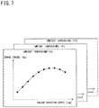
- FIG. 7 shows an example of the aggregated log information collected in the communication system according to the embodiment of the present disclosure. It is noted that, in FIG. 7 , the horizontal axis indicates the engine rotation speed and the vertical axis indicates the brake torque.
- the aggregated log information including the correspondence relationship between the engine rotation speed and the brake torque when the ambient temperature is 5° C., 10° C., and 15° C., which is required by the administrator, is accumulated in the server 181 .
- the aggregated log information accumulated in the server 181 is fed back to the manufacturer for the vehicle 1 , for example.
- the manufacturer for the vehicle 1 plots, on a graph, a traveling performance curve for each of cases where the ambient temperature is 5° C., 10° C., and 15° C., using the aggregated log information.
- the manufacturer for the vehicle 1 can acquire the traveling performance curve of the engine in each environmental condition, and thus, it is possible to appropriately adjust, for example, a setting value or the like in a control program for the engine in accordance with the environmental condition in which the vehicle 1 travels.
- the log notification information indicates a plurality of start conditions associated with one trigger function unit.
- the log notification information is not limited thereto.
- the log notification information may indicate a plurality of trigger function units and a set of a plurality of start conditions respectively associated with the plurality of trigger function units.
- the processing unit 24 in the log collection device 101 gives a command for log collection when the plurality of start conditions are all satisfied, for example.
- FIG. 8 and FIG. 9 are charts showing an example of a sequence in a case where the relay device has received log notification information in the communication system according to the embodiment of the present disclosure.
- FIG. 9 shows continuation from the sequence shown in FIG. 8 .
- the administrator inputs, to the server 181 , a command for performing, in the vehicle 1 , log collection for the correspondence relationship between the engine rotation speed and the brake torque when the ambient temperature is 9° C. to 11° C., the intake pressure is 45 kPa to 55 kPa, and the water temperature is 45° C. to 55° C. in the vehicle 1 , for example (step S 202 ).
- the server 181 In response to the input from the administrator, the server 181 generates log notification information and transmits the generated log notification information to the relay device 151 in the vehicle 1 (step S 204 ).
- the log notification information indicates, for example, an engine rotation speed and a brake torque as types of log target information, the address of the engine ECU 111 E, i.e., the log address as the log target function unit, the addresses of the plurality of trigger function units, and the start conditions respectively associated with the addresses of the plurality of trigger function units.
- the addresses of the plurality of trigger function units are, for example, the address of the temperature sensor 111 B, i.e., the first trigger address, the address (hereinafter, may be referred to as second trigger address) of the intake pressure sensor 111 C, and the address (hereinafter, may be referred to as third trigger address) of the water temperature sensor 111 D.
- the start conditions respectively associated with the first trigger address, the second trigger address, and the third trigger address are that the ambient temperature is 9° C. to 11° C., the intake pressure is 45 kPa to 55 kPa, and the water temperature is 45° C. to 55° C.
- the relay device 151 when the relay device 151 has received the log notification information from the server 181 , the relay device 151 generates start condition information and command information on the basis of the received log notification information (step S 206 ).
- the processing unit 24 in the relay device 151 has received the log notification information from the server 181 via the TCU 111 A, the relay processing unit 51 , and the acquisition unit 21 , the processing unit 24 acquires the following information from the received log notification information.
- the processing unit 24 acquires: the engine rotation speed and the brake torque as types of log target information; the log address; the first trigger address, the second trigger address, and the third trigger address; and conditions that the ambient temperature is 9° C. to 11° C., the intake pressure is 45 kPa to 55 kPa, and the water temperature is 45° C. to 55° C., as the start conditions respectively associated with the first trigger address, the second trigger address, and the third trigger address.
- the processing unit 24 generates start condition information SC 1 including the ambient temperature of 9° C. to 11° C. as the start condition, with the acquired first trigger address set as the destination address.
- the processing unit 24 generates start condition information SC 2 including the intake pressure of 45 kPa to 55 kPa as the start condition, with the acquired second trigger address set as the destination address.
- the processing unit 24 generates start condition information SC 3 including the water temperature of 45° C. to 55° C. as the start condition, with the acquired third trigger address set as the destination address.
- the processing unit 24 generates command information including the engine rotation speed and the brake torque as types of log target information, with the acquired log address set as the destination address.
- the relay device 151 transmits the generated start condition information SC 1 to the temperature sensor 111 B (step S 208 ).
- the processing unit 24 in the relay device 151 transmits the generated start condition information SC 1 to the temperature sensor 111 B via the notification unit 22 and the relay processing unit 51 .
- the temperature sensor 111 B sets the start condition included in the received start condition information SC 1 , i.e., the ambient temperature of 9° C. to 11° C., as a trigger condition (step S 210 ).
- the relay device 151 transmits the generated start condition information SC 2 to the intake pressure sensor 111 C (step S 212 ).
- the processing unit 24 in the relay device 151 transmits the generated start condition information SC 2 to the intake pressure sensor 111 C via the notification unit 22 and the relay processing unit 51 .
- the intake pressure sensor 111 C sets the start condition included in the received start condition information SC 2 , i.e., the intake pressure of 45 kPa to 55 kPa, as a trigger condition (step S 214 ).
- the relay device 151 transmits the generated start condition information SC 3 to the water temperature sensor 111 D (step S 216 ).
- the processing unit 24 in the relay device 151 transmits the generated start condition information SC 3 to the water temperature sensor 111 D via the notification unit 22 and the relay processing unit 51 .
- the water temperature sensor 111 D sets the start condition included in the received start condition information SC 3 , i.e., the water temperature of 45° C. to 55° C., as a trigger condition (step S 218 ).
- the temperature sensor 111 B measures an ambient temperature in a range of 9° C. to 11° C., and thus detects that the trigger condition for 9° C. to 11° C. is satisfied (step S 220 ).
- the temperature sensor 111 B transmits trigger detection information TD 1 indicating that the trigger condition for 9° C. to 11° C. is satisfied, to the relay device 151 (step S 222 ).
- the relay device 151 when the relay device 151 has received the trigger detection information TD 1 from the temperature sensor 111 B, the relay device 151 turns on the corresponding flag on the basis of the received trigger detection information TD 1 (step S 224 ).
- the processing unit 24 in the relay device 151 has received the trigger detection information TD 1 from the temperature sensor 111 B via the relay processing unit 51 and the acquisition unit 21 , the processing unit 24 recognizes that the ambient temperature in a range of 9° C. to 11° C. has been measured by the temperature sensor 111 B, on the basis of the received trigger detection information TD 1 .
- the processing unit 24 turns on a flag F 1 which indicates that the ambient temperature in a range of 9° C. to 11° C. has been measured by the temperature sensor 111 B, for example.
- the flag F 1 is turned off when a predetermined duration period has elapsed since the flag was turned on, for example.
- the predetermined duration period is set in accordance with the degree of change in the ambient temperature.
- step S 220 to step S 224 is repeated every time the trigger condition for 9° C. to 11° C. is satisfied in the temperature sensor 111 B, for example.
- the intake pressure sensor 111 C measures an intake pressure in a range of 45 kPa to 55 kPa, and thus detects that the trigger condition for 45 kPa to 55 kPa is satisfied (step S 226 ).
- the intake pressure sensor 111 C transmits trigger detection information TD 2 indicating that the trigger condition for 45 kPa to 55 kPa is satisfied, to the relay device 151 (step S 228 ).
- the relay device 151 when the relay device 151 has received the trigger detection information TD 2 from the intake pressure sensor 111 C, the relay device 151 turns on the corresponding flag on the basis of the received trigger detection information TD 2 (step S 230 ).
- the processing unit 24 in the relay device 151 has received the trigger detection information TD 2 from the intake pressure sensor 111 C via the relay processing unit 51 and the acquisition unit 21 , the processing unit 24 recognizes that the intake pressure in a range of 45 kPa to 55 kPa has been measured by the intake pressure sensor 111 C, on the basis of the received trigger detection information TD 2 .
- the processing unit 24 turns on a flag F 2 which indicates that the intake pressure in a range of 45 kPa to 55 kPa has been measured by the intake pressure sensor 111 C, for example.
- the flag F 2 is turned off when a predetermined duration period has elapsed since the flag was turned on, for example.
- the predetermined duration period is set in accordance with the degree of change in the intake pressure, for example.
- step S 226 to step S 230 is repeated every time the trigger condition for 45 kPa to 55 kPa is satisfied in the intake pressure sensor 111 C, for example.
- the water temperature sensor 111 D measures a water temperature in a range of 45° C. to 55° C., and thus detects that the trigger condition for 45° C. to 55° C. is satisfied (step S 232 ).
- the water temperature sensor 111 D transmits trigger detection information TD 3 indicating that the trigger condition for 45° C. to 55° C. is satisfied, to the relay device 151 (step S 234 ).
- the relay device 151 when the relay device 151 has received the trigger detection information TD 3 from the water temperature sensor 111 D, the relay device 151 turns on the corresponding flag on the basis of the received trigger detection information TD 3 (step S 236 ).
- the processing unit 24 in the relay device 151 has received the trigger detection information TD 3 from the water temperature sensor 111 D via the relay processing unit 51 and the acquisition unit 21 , the processing unit 24 recognizes that the water temperature in a range of 45° C. to 55° C. has been measured by the water temperature sensor 111 D, on the basis of the received trigger detection information TD 3 .
- the processing unit 24 turns on a flag F 3 which indicates that the water temperature in a range of 45° C. to 55° C. has been measured by the water temperature sensor 111 D, for example.
- the flag F 3 is turned off when a predetermined duration period has elapsed since the flag was turned on, for example.
- the predetermined duration period is set in accordance with the degree of change in the water temperature, for example.
- step S 232 to step S 236 is repeated every time the trigger condition for 45° C. to 55° C. is satisfied in the water temperature sensor 111 D, for example.
- the processing unit 24 in the relay device 151 transmits the already generated command information to the engine ECU 111 E via the relay processing unit 51 (step S 238 ).
- the engine ECU 111 E acquires, in accordance with the received command information, the log target information included in the command information, i.e., each of information indicating the engine rotation speed and information indicating the brake torque, for one point (step S 240 ).
- the engine ECU 111 E transmits log information including the acquired information, to the relay device 151 (step S 242 ).
- the relay device 151 stores the received log information (step S 244 ).
- the processing unit 24 in the relay device 151 when the processing unit 24 in the relay device 151 has received the log information from the engine ECU 111 E via the relay processing unit 51 and the acquisition unit 21 , the processing unit 24 incorporates the start conditions that the ambient temperature is 9° C. to 11° C., the intake pressure is 45 kPa to 55 kPa, and the water temperature is 45° C. to 55° C., into the received log information. Then, the processing unit 24 stores the log information into the storage unit 23 .
- step S 244 is repeated every time the condition that all the flags F 1 to F 3 are turned on is satisfied.
- the relay device 151 aggregates the respective pieces of stored log information, thereby generating aggregated log information (step S 246 ).
- the processing unit 24 in the relay device 151 aggregates the respective pieces of log information stored in the storage unit 23 , thereby generating aggregated log information.
- the processing unit 24 transmits the generated aggregated log information to the server 181 via the relay processing unit 51 (step S 248 ).
- the server 181 when the server 181 has received the aggregated log information from the relay device 151 , the server 181 performs accumulation processing for accumulating the received aggregated log information (step S 250 ).
- the start conditions are that the ambient temperature, the intake pressure, and the water temperature become values within specific ranges.
- the start conditions are not limited thereto.
- the start conditions may be that the ambient temperature, the intake pressure, and the water temperature become specific values.
- steps S 208 and S 210 , steps S 212 and S 214 , and steps S 216 and S 218 is not limited to the above order. A part or the entirety of the order may be changed.
- steps S 220 to S 224 , steps S 226 to S 230 , and steps S 232 to S 236 is not limited to the above order. A part or the entirety of the order may be changed.
- each flag F 1 to F 3 is automatically turned off when the corresponding duration period has elapsed since the flag was turned on.
- Each flag F 1 to F 3 may be turned on during a period in which the corresponding trigger condition is satisfied, and may be turned off when the corresponding trigger condition is no longer satisfied.
- FIG. 10 is a chart showing an example of a sequence in a case where the temperature sensor has received start condition information in the on-vehicle communication system according to the embodiment of the present disclosure.
- the relay device 151 transmits the start condition information SC 1 to the temperature sensor 111 B (step S 302 ).
- the temperature sensor 111 B sets the start condition included in the received start condition information SC 1 , i.e., an ambient temperature of 9° C. to 11° C., as a trigger condition (step S 304 ).
- the temperature sensor 111 B measures an ambient temperature in a range of 9° C. to 11° C., and thus detects that the trigger condition for 9° C. to 11° C. is satisfied (step S 306 ).
- the temperature sensor 111 B transmits the trigger detection information TD 1 indicating that the trigger condition for 9° C. to 11° C. is satisfied, to the relay device 151 (step S 308 ).
- the relay device 151 when the relay device 151 has received the trigger detection information TD 1 from the temperature sensor 111 B, the relay device 151 turns on the flag F 1 on the basis of the received trigger detection information TD 1 (step S 310 ).
- the predetermined duration period is not set for the flag F 1 .
- the temperature sensor 111 B measures an ambient temperature other than 9° C. to 11° C., and thus no longer detects that the trigger condition for 9° C. to 11° C. is satisfied (step S 312 ).
- the temperature sensor 111 B transmits trigger non-detection information ND 1 indicating that the trigger condition for 9° C. to 11° C. is not satisfied, to the relay device 151 (step S 314 ).
- the relay device 151 when the relay device 151 has received the trigger non-detection information ND 1 from the temperature sensor 111 B, the relay device 151 turns off the flag F 1 on the basis of the received trigger non-detection information ND 1 (step S 316 ).
- step S 306 when it is detected that the trigger condition for 45 kPa to 55 kPa is satisfied (step S 306 ), the trigger detection information TD 2 is transmitted to the relay device 151 (step S 308 ), and when it is no longer detected that the trigger condition for 45 kPa to 55 kPa is satisfied (step S 312 ), trigger non-detection information ND 2 is transmitted to the relay device 151 (step S 314 ).
- the relay device 151 when the relay device 151 has received the trigger detection information TD 2 from the intake pressure sensor 111 C, the relay device 151 turns on the flag F 2 (step S 310 ), and when the relay device 151 has received the trigger non-detection information ND 2 from the intake pressure sensor 111 C, the relay device 151 turns off the flag F 2 (step S 316 ).
- step S 306 when it is detected that the trigger condition for 45° C. to 55° C. is satisfied (step S 306 ), the trigger detection information TD 3 is transmitted to the relay device 151 (step S 308 ), and when it is no longer detected that the trigger condition for 45° C. to 55° C. is satisfied (step S 312 ), trigger non-detection information ND 3 is transmitted to the relay device 151 (step S 314 ).
- the relay device 151 when the relay device 151 has received the trigger detection information TD 3 from the water temperature sensor 111 D, the relay device 151 turns on the flag F 3 (step S 310 ), and when the relay device 151 has received the trigger non-detection information ND 3 from the water temperature sensor 111 D, the relay device 151 turns off the flag F 3 (step S 316 ).
- FIG. 11 shows an example of aggregated log information collected in the communication system according to the embodiment of the present disclosure. It is noted that how to read FIG. 11 is the same as in FIG. 7 .
- the aggregated log information including the correspondence relationship between the engine rotation speed and the brake torque when the ambient temperature is 9° C. to 11° C., the intake pressure is 45 kPa to 55 kPa, and the water temperature is 45° C. to 55° C., which is required by the administrator, is accumulated in the server 181 .
- FIG. 11 it is possible to plot, on a graph, a traveling performance curve for a case where the ambient temperature is 9° C. to 11° C., the intake pressure is 45 kPa to 55 kPa, and the water temperature is 45° C. to 55° C., using the aggregated log information accumulated in the server 181 .
- the log notification information indicates a plurality of start conditions associated with one trigger function unit.
- the log notification information is not limited thereto.
- the log notification information may indicate a plurality of trigger function units and a plurality of sets of start conditions respectively associated with the plurality of trigger function units.
- the processing unit 24 in the log collection device 101 gives a command for log collection when the start conditions in any one of the plurality of sets are all satisfied.
- FIG. 12 , FIG. 13 , and FIG. 14 are charts showing an example of a sequence in a case where the relay device has received log notification information in the communication system according to the embodiment of the present disclosure.
- FIG. 13 shows continuation from the sequence shown in FIG. 12 .
- FIG. 14 shows continuation from the sequence shown in FIG. 13 .
- the administrator inputs, to the server 181 , a command for performing, in the vehicle 1 , log collection for the correspondence relationship between the engine rotation speed and the brake torque when the vehicle 1 is in the following states ST 1 , ST 2 , ST 3 , for example (step S 402 ).
- the state ST 1 is a state in which the ambient temperature is 39° C. to 41° C., the intake pressure is 45 kPa to 55 kPa, and the water temperature is 45° C. to 55° C.
- the state ST 2 is a state in which the ambient temperature is 19° C. to 21° C., the intake pressure is 81 kPa to 99 kPa, and the water temperature is 20° C. to 30° C.
- the state ST 3 is a state in which the ambient temperature is ⁇ 1° C. to 1° C., the intake pressure is 9 kPa to 11 kPa, and the water temperature is 0° C. to 10° C.
- the server 181 In response to the input from the administrator, the server 181 generates log notification information, and transmits the generated log notification information to the relay device 151 in the vehicle 1 (step S 404 ).
- the log notification information indicates, for example, the engine rotation speed and the brake torque as types of log target information, the address of the engine ECU 111 E, i.e., the log address as the log target function unit, and sets CL 1 , CL 2 , CL 3 .
- each of the sets CL 1 , CL 2 , CL 3 includes the addresses of a plurality of trigger function units, and start conditions respectively associated with the addresses of the plurality of trigger function units.
- the sets CL 1 , CL 2 , CL 3 are generated on the basis of the states ST 1 , ST 2 , ST 3 , respectively.
- the addresses of the plurality of trigger function units in each of the sets CL 1 , CL 2 , CL 3 are the address of the temperature sensor 111 B, i.e., the first trigger address, the address of the intake pressure sensor 111 C, i.e., the second trigger address, and the address of the water temperature sensor 111 D, i.e., the third trigger address.
- the start conditions included in the set CL 1 and respectively associated with the first trigger address, the second trigger address, and the third trigger address are that the ambient temperature is 39° C. to 41° C., the intake pressure is 45 kPa to 55 kPa, and the water temperature is 45° C. to 55° C.
- the start conditions included in the set CL 2 and respectively associated with the first trigger address, the second trigger address, and the third trigger address are that the ambient temperature is 19° C. to 21° C., the intake pressure is 81 kPa to 99 kPa, and the water temperature is 20° C. to 30° C.
- the start conditions included in the set CL 3 and respectively associated with the first trigger address, the second trigger address, and the third trigger address are that the ambient temperature is ⁇ 1° C. to 1° C., the intake pressure is 9 kPa to 11 kPa, and the water temperature is 0° C. to 10° C.
- the relay device 151 when the relay device 151 has received the log notification information from the server 181 , the relay device 151 generates start condition information and command information on the basis of the received log notification information (step S 406 ).
- the processing unit 24 in the relay device 151 has received the log notification information from the server 181 via the TCU 111 A, the relay processing unit 51 , and the acquisition unit 21 , the processing unit 24 acquires the following information from the received log notification information.
- the processing unit 24 acquires the engine rotation speed and the brake torque as types of log target information, the log address, and the sets CL 1 , CL 2 , CL 3 .
- the processing unit 24 On the basis of the acquired sets CL 1 , CL 2 , CL 3 , the processing unit 24 generates start condition information SC 4 including an ambient temperature of 39° C. to 41° C., an ambient temperature of 19° C. to 21° C., and an ambient temperature of ⁇ 1° C. to 1° C. as the start conditions, with the first trigger address set as the destination address.
- the processing unit 24 generates start condition information SC 5 including an intake pressure of 45 kPa to 55 kPa, an intake pressure of 81 kPa to 99 kPa, and an intake pressure of 9 kPa to 11 kPa as the start conditions, with the second trigger address set as the destination address.
- the processing unit 24 On the basis of the acquired sets CL 1 , CL 2 , CL 3 , the processing unit 24 generates start condition information SC 6 including a water temperature of 45° C. to 55° C., a water temperature of 20° C. to 30° C., and a water temperature of 0° C. to 10° C. as the start conditions, with the third trigger address set as the destination address.
- the processing unit 24 generates command information including the engine rotation speed and the brake torque as types of log target information, with the acquired log address set as the destination address.
- the relay device 151 transmits the generated start condition information SC 4 to the temperature sensor 111 B (step S 408 ).
- the processing unit 24 in the relay device 151 transmits the generated start condition information SC 4 to the temperature sensor 111 B via the notification unit 22 and the relay processing unit 51 .
- the temperature sensor 111 B sets the start conditions included in the received start condition information SC 4 , i.e., the ambient temperature of 39° C. to 41° C., the ambient temperature of 19° C. to 21° C., and the ambient temperature of ⁇ 1° C. to 1° C., as trigger conditions T 41 , T 42 , and T 43 (step S 410 ).
- the relay device 151 transmits the generated start condition information SC 5 to the intake pressure sensor 111 C (step S 412 ).
- the processing unit 24 in the relay device 151 transmits the generated start condition information SC 5 to the intake pressure sensor 111 C via the notification unit 22 and the relay processing unit 51 .
- the intake pressure sensor 111 C sets the start conditions included in the received start condition information SC 5 , i.e., the intake pressure of 45 kPa to 55 kPa, the intake pressure of 81 kPa to 99 kPa, and the intake pressure of 9 kPa to 11 kPa, as trigger conditions T 51 , T 52 , and T 53 (step S 414 ).
- the relay device 151 transmits the generated start condition information SC 6 to the water temperature sensor 111 D (step S 416 ).
- the processing unit 24 in the relay device 151 transmits the generated start condition information SC 6 to the water temperature sensor 111 D via the notification unit 22 and the relay processing unit 51 .
- the water temperature sensor 111 D sets the start conditions included in the received start condition information SC 6 , i.e., the water temperature of 45° C. to 55° C., the water temperature of 20° C. to 30° C., and the water temperature of 0° C. to 10° C., as trigger conditions T 61 , T 62 , and T 63 (step S 418 ).
- the temperature sensor 111 B measures an ambient temperature in any one of ranges of 39° C. to 41° C., 19° C. to 21° C., and ⁇ 1° C. to 1° C., and thus detects that the trigger condition T 41 , T 42 , or T 43 is satisfied (step S 420 ).
- the temperature sensor 111 B transmits trigger detection information TD 4 indicating that the trigger condition for 39° C. to 41° C. is satisfied, the trigger condition for 19° C. to 21° C. is satisfied, or the trigger condition for ⁇ 1° C. to 1° C. is satisfied, to the relay device 151 (step S 422 ).
- the relay device 151 when the relay device 151 has received the trigger detection information TD 4 from the temperature sensor 111 B, the relay device 151 turns on the corresponding flag on the basis of the received trigger detection information TD 4 (step S 424 ).
- the processing unit 24 in the relay device 151 when the processing unit 24 in the relay device 151 has received the trigger detection information TD 4 from the temperature sensor 111 B via the relay processing unit 51 and the acquisition unit 21 , the processing unit 24 performs the following processing.
- the processing unit 24 turns on a flag F 41 which indicates that an ambient temperature in a range of 39° C. to 41° C. has been measured by the temperature sensor 111 B.
- the processing unit 24 turns on a flag F 42 which indicates that an ambient temperature in a range of 19° C. to 21° C. has been measured by the temperature sensor 111 B.
- the processing unit 24 turns on a flag F 43 which indicates that an ambient temperature in a range of ⁇ 1° C. to 1° C. has been measured by the temperature sensor 111 B.
- the temperature sensor 111 B measures an ambient temperature that is not in any of ranges of 39° C. to 41° C., 19° C. to 21° C., and ⁇ 1° C. to 1° C., and thus no longer detects that the trigger conditions T 41 , T 42 , and T 43 are satisfied (step S 426 ).
- the temperature sensor 111 B transmits trigger non-detection information ND 4 indicating that the trigger condition for 39° C. to 41° C. is not satisfied, the trigger condition for 19° C. to 21° C. is not satisfied, or the trigger condition for ⁇ 1° C. to 1° C. is not satisfied, to the relay device 151 (step S 428 ).
- the relay device 151 when the relay device 151 has received the trigger non-detection information ND 4 from the temperature sensor 111 B, the relay device 151 turns off the corresponding flag on the basis of the received trigger non-detection information ND 4 (step S 430 ).
- the processing unit 24 in the relay device 151 when the processing unit 24 in the relay device 151 has received the trigger non-detection information ND 4 from the temperature sensor 111 B via the relay processing unit 51 and the acquisition unit 21 , the processing unit 24 performs the following processing.
- the processing unit 24 turns off the flag F 41 .
- the processing unit 24 turns off the flag F 42 .
- the processing unit 24 turns off the flag F 43 .
- step S 420 to step S 430 is repeated every time any one of the trigger conditions T 41 , T 42 , and T 43 is satisfied in the temperature sensor 111 B, for example.
- the intake pressure sensor 111 C measures an intake pressure in any of ranges of 45 kPa to 55 kPa, 81 kPa to 99 kPa, and 9 kPa to 11 kPa, and thus detects that the trigger condition T 51 , T 52 , or T 53 is satisfied (step S 432 ).
- the intake pressure sensor 111 C transmits trigger detection information TD 5 indicating that the trigger condition for 45 kPa to 55 kPa is satisfied, the trigger condition for 81 kPa to 99 kPa is satisfied, or the trigger condition for 9 kPa to 11 kPa is satisfied, to the relay device 151 (step S 434 ).
- the relay device 151 when the relay device 151 has received the trigger detection information TD 5 from the intake pressure sensor 111 C, the relay device 151 turns on the corresponding flag on the basis of the received trigger detection information TD 5 (step S 436 ).
- the processing unit 24 in the relay device 151 when the processing unit 24 in the relay device 151 has received the trigger detection information TD 5 from the intake pressure sensor 111 C via the relay processing unit 51 and the acquisition unit 21 , the processing unit 24 performs the following processing.
- the processing unit 24 turns on a flag F 51 which indicates that an intake pressure in a range of 45 kPa to 55 kPa has been measured by the intake pressure sensor 111 C.
- the processing unit 24 turns on a flag F 52 which indicates that an intake pressure in a range of 81 kPa to 99 kPa has been measured by the intake pressure sensor 111 C.
- the processing unit 24 turns on a flag F 53 which indicates that an intake pressure in a range of 9 kPa to 11 kPa has been measured by the intake pressure sensor 111 C.
- the intake pressure sensor 111 C measures an intake pressure that is not in any of ranges of 45 kPa to 55 kPa, 81 kPa to 99 kPa, and 9 kPa to 11 kPa, and thus no longer detects that the trigger conditions T 51 , T 52 , and T 53 are satisfied (step S 438 ).
- the intake pressure sensor 111 C transmits trigger non-detection information ND 5 indicating that the trigger condition for 45 kPa to 55 kPa is not satisfied, the trigger condition for 81 kPa to 99 kPa is not satisfied, or the trigger condition for 9 kPa to 11 kPa is not satisfied, to the relay device 151 (step S 440 ).
- the relay device 151 when the relay device 151 has received the trigger non-detection information ND 5 from the intake pressure sensor 111 C, the relay device 151 turns off the corresponding flag on the basis of the received trigger non-detection information ND 5 (step S 442 ).
- the processing unit 24 in the relay device 151 when the processing unit 24 in the relay device 151 has received the trigger non-detection information ND 5 from the intake pressure sensor 111 C via the relay processing unit 51 and the acquisition unit 21 , the processing unit 24 performs the following processing.
- the processing unit 24 turns off the flag F 51 .
- the processing unit 24 turns off the flag F 52 .
- the processing unit 24 turns off the flag F 53 .
- step S 432 to step S 442 is repeated every time any one of the trigger conditions T 51 , T 52 , and T 53 is satisfied in the intake pressure sensor 111 C, for example.
- the water temperature sensor 111 D measures a water temperature in any one of ranges of 45° C. to 55° C., 20° C. to 30° C., and 0° C. to 10° C., and thus detects that the trigger condition T 61 , T 62 , or T 63 is satisfied (step S 444 ).
- the water temperature sensor 111 D transmits trigger detection information TD 6 indicating that the trigger condition for 45° C. to 55° C. is satisfied, the trigger condition for 20° C. to 30° C. is satisfied, or the trigger condition for 0° C. to 10° C. is satisfied, to the relay device 151 (step S 446 ).
- the relay device 151 when the relay device 151 has received the trigger detection information TD 6 from the water temperature sensor 111 D, the relay device 151 turns on the corresponding flag on the basis of the received trigger detection information TD 6 (step S 448 ).
- the processing unit 24 in the relay device 151 when the processing unit 24 in the relay device 151 has received the trigger detection information TD 6 from the water temperature sensor 111 D via the relay processing unit 51 and the acquisition unit 21 , the processing unit 24 performs the following processing.
- the processing unit 24 turns on a flag F 61 which indicates that a water temperature in a range of 45° C. to 55° C. has been measured by the water temperature sensor 111 D.
- the processing unit 24 turns on a flag F 62 which indicates that a water temperature in a range of 20° C. to 30° C. has been measured by the water temperature sensor 111 D.
- the processing unit 24 turns on a flag F 63 which indicates that a water temperature in a range of 0° C. to 10° C. has been measured by the water temperature sensor 111 D.
- the water temperature sensor 111 D measures a water temperature that is not in any of ranges of 45° C. to 55° C., 20° C. to 30° C., and 0° C. to 10° C., and thus no longer detects that the trigger conditions T 61 , T 62 , and T 63 are satisfied (step S 450 ).
- the water temperature sensor 111 D transmits trigger non-detection information ND 6 indicating that the trigger condition for 45° C. to 55° C. is not satisfied, the trigger condition for 20° C. to 30° C. is not satisfied, or the trigger condition for 0° C. to 10° C. is not satisfied, to the relay device 151 (step S 452 ).
- the relay device 151 when the relay device 151 has received the trigger non-detection information ND 6 from the water temperature sensor 111 D, the relay device 151 turns off the corresponding flag on the basis of the received trigger non-detection information ND 6 (step S 454 ).
- the processing unit 24 in the relay device 151 when the processing unit 24 in the relay device 151 has received the trigger non-detection information ND 6 from the water temperature sensor 111 D via the relay processing unit 51 and the acquisition unit 21 , the processing unit 24 performs the following processing.
- the processing unit 24 turns off the flag F 61 .
- the processing unit 24 turns off the flag F 62 .
- the processing unit 24 turns off the flag F 63 .
- step S 444 to step S 454 is repeated every time any one of the trigger conditions T 61 , T 62 , and T 63 is satisfied in the water temperature sensor 111 D, for example.
- the processing unit 24 in the relay device 151 transmits the already generated command information to the engine ECU 111 E via the relay processing unit 51 (step S 456 ).
- the engine ECU 111 E acquires, in accordance with the received command information, the log target information included in the command information, i.e., each of information indicating the engine rotation speed and information indicating the brake torque, for one point (step S 458 ).
- the engine ECU 111 E transmits log information including the acquired information, to the relay device 151 (step S 460 ).
- the relay device 151 stores the received log information (step S 462 ).
- the processing unit 24 in the relay device 151 when the processing unit 24 in the relay device 151 has received the log information from the engine ECU 111 E via the relay processing unit 51 and the acquisition unit 21 , the processing unit 24 performs the following processing.
- the processing unit 24 incorporates the start conditions included in the set CL 1 that the ambient temperature is 39° C. to 41° C., the intake pressure is 45 kPa to 55 kPa, and the water temperature is 45° C. to 55° C., into the received log information.
- the processing unit 24 incorporates the start conditions included in the set CL 2 that the ambient temperature is 19° C. to 21° C., the intake pressure is 81 kPa to 99 kPa, and the water temperature is 20° C. to 30° C., into the received log information.
- the processing unit 24 incorporates the start conditions included in the set CL 3 that the ambient temperature is ⁇ 1° C. to 1° C., the intake pressure is 9 kPa to 11 kPa, and the water temperature is 0° C. to 10° C., into the received log information. Then, the processing unit 24 stores the log information into the storage unit 23 .
- step S 456 to step S 462 is repeated every time any one of the condition that the flags F 41 , F 51 , F 61 are all turned on, the condition that the flags F 42 , F 52 , F 62 are all turned on, and the condition that the flags F 43 , F 53 , F 63 are all turned on, is satisfied.
- the relay device 151 aggregates the respective pieces of stored log information, thereby generating aggregated log information (step S 464 ).
- the processing unit 24 in the relay device 151 aggregates the respective pieces of log information stored in the storage unit 23 , thereby generating aggregated log information.
- the processing unit 24 transmits the generated aggregated log information to the server 181 via the relay processing unit 51 (step S 466 ).
- the server 181 when the server 181 has received the aggregated log information from the relay device 151 , the server 181 performs accumulation processing for accumulating the received aggregated log information (step S 468 ).
- the start conditions are that the ambient temperature, the intake pressure, and the water temperature become values within specific ranges.
- the start conditions are not limited thereto.
- the start conditions may be that the ambient temperature, the intake pressure, and the water temperature become specific values.
- steps S 408 and S 410 , steps S 412 and S 414 , and steps S 416 and S 418 is not limited to the above order. A part or the entirety of the order may be changed.
- steps S 420 to S 430 , steps S 432 to S 442 , and steps S 444 to S 454 is not limited to the above order. A part or the entirety of the order may be changed.
- each flag F 41 to F 43 , F 51 to F 53 , F 61 to F 63 is turned on during a period in which the corresponding trigger condition is satisfied (steps S 424 , S 436 , S 448 ), and is turned off when the corresponding trigger condition is no longer satisfied (steps S 430 , S 442 , S 454 ).
- the present disclosure is not limited thereto.
- Each flag F 41 to F 43 , F 51 to F 53 , F 61 to F 63 may be automatically turned off when a corresponding duration period has elapsed since the flag was turned on.
- FIG. 15 shows an example of aggregated log information collected in the communication system according to the embodiment of the present disclosure. It is noted that how to read FIG. 15 is the same as in FIG. 7 .
- the aggregated log information including the correspondence relationship between the engine rotation speed and the brake torque in the above states ST 1 , ST 2 , ST 3 , which is required by the administrator, is accumulated in the server 181 .
- the communication system is configured such that the log notification information includes the type of log target information.
- the present disclosure is not limited thereto.
- the log notification information may not include the type of log target information.
- the log target function unit is the engine ECU 111 E.
- the log target function unit is not limited thereto.
- the log target function unit may be an on-vehicle ECU 111 other than the engine ECU 111 E.
- the trigger function unit is the temperature sensor 111 B, the intake pressure sensor 111 C, or the water temperature sensor 111 D.
- the trigger function unit is not limited thereto.
- the trigger function unit may be an on-vehicle ECU 111 other than the temperature sensor 111 B, the intake pressure sensor 111 C, and the water temperature sensor 111 D.
- At least one of the number of start conditions and the number of trigger function units is plural. However, these numbers are not limited thereto. Both of the number of start conditions and the number of trigger function units may be one.
- the on-vehicle control device in the on-vehicle network described in PATENT LITERATURE 1 performs, for example, measurement of the environment and the state of a vehicle, control for components constituting the vehicle, and the like.
- a result of the measurement and a result of the control by the on-vehicle control device are recorded as logs because they are useful for vehicle development or the like.
- the data amount becomes enormous. Technology for efficiently collecting logs is required.
- the relay device can relay data between a plurality of function units mounted on the vehicle 1 .
- the acquisition unit 21 receives a log notification indicating a log target function unit which is a function unit that is a target of log collection, a start condition for log collection, and a trigger function unit which is a function unit capable of determination for the start condition, from an external device outside the vehicle 1 , e.g., from the server 181 .
- the notification unit 22 notifies the trigger function unit of the start condition indicated by the log notification.
- the processing unit 24 gives a command for log collection to the log target function unit.
- the log notification indicates a plurality of start conditions associated with one trigger function unit.
- the log notification indicates a plurality of trigger function units and a set of a plurality of start conditions respectively associated with the plurality of trigger function units. Then, when the plurality of start conditions are all satisfied, the processing unit 24 gives a command for log collection.
- logs in a specific vehicle state and a specific vehicle environment, which are required for vehicle development can be collected in a specified manner.
- the log notification indicates a plurality of the sets. Then, when the plurality of start conditions in any one of the plurality of sets are all satisfied, the processing unit 24 gives a command for log collection.
- An on-vehicle communication device capable of relaying data between a plurality of function units mounted on a vehicle, the on-vehicle communication device including:
- a log notification acquisition unit configured to receive, from an external device outside the vehicle, a log notification indicating a log target function unit which is the function unit that is a target of log collection, a start condition for log collection, and a trigger function unit which is the function unit capable of determination for the start condition;
- a notification unit configured to notify the trigger function unit of the start condition indicated by the log notification
- a command unit configured to, in response to a notification that the start condition is satisfied from the trigger function unit, give a command for log collection to the log target function unit,
- the on-vehicle communication device is a gateway device
- the function units are a telematics communication unit (TCU), an autonomous driving electronic control unit (ECU), an engine ECU, a sensor, a navigation device, a human machine interface, and a camera,
- the log notification indicates a log address which is an address of the log target function unit, the start condition, and a trigger address which is an address of the trigger function unit,
- the notification unit notifies the trigger function unit of the start condition indicated by the log notification, using the trigger address, and
- the command unit gives the command to the log target function unit, using the log address, in response to the notification that the start condition is satisfied from the trigger function unit.
Landscapes
- Engineering & Computer Science (AREA)
- General Physics & Mathematics (AREA)
- Physics & Mathematics (AREA)
- Computer Networks & Wireless Communication (AREA)
- Signal Processing (AREA)
- Theoretical Computer Science (AREA)
- General Engineering & Computer Science (AREA)
- Quality & Reliability (AREA)
- Mechanical Engineering (AREA)
- Automation & Control Theory (AREA)
- Computer Hardware Design (AREA)
- Small-Scale Networks (AREA)
- Debugging And Monitoring (AREA)
Abstract
Description
-
- 1 vehicle
- 11 external network
- 12 on-vehicle network
- 21 acquisition unit
- 22 notification unit
- 23 storage unit
- 24 processing unit (command unit)
- 51 relay processing unit
- 52 communication port
- 101 log collection device
- 111 on-vehicle ECU
- 111A TCU
- 111B temperature sensor
- 111C intake pressure sensor
- 111D water temperature sensor
- 111E engine ECU
- 151 relay device (on-vehicle communication device)
- 161 wireless base station device
- 181 server
- 201 communication system
- 301 on-vehicle communication system
Claims (10)
Applications Claiming Priority (4)
| Application Number | Priority Date | Filing Date | Title |
|---|---|---|---|
| JP2017134273A JP6787262B2 (en) | 2017-07-10 | 2017-07-10 | In-vehicle communication device, log collection method and log collection program |
| JP2017-134273 | 2017-07-10 | ||
| JPJP2017-134273 | 2017-07-10 | ||
| PCT/JP2018/022352 WO2019012890A1 (en) | 2017-07-10 | 2018-06-12 | Vehicle-mounted communications device, log collection method, and log collection program |
Publications (2)
| Publication Number | Publication Date |
|---|---|
| US20200134937A1 US20200134937A1 (en) | 2020-04-30 |
| US11373464B2 true US11373464B2 (en) | 2022-06-28 |
Family
ID=65001275
Family Applications (1)
| Application Number | Title | Priority Date | Filing Date |
|---|---|---|---|
| US16/629,996 Active 2039-02-19 US11373464B2 (en) | 2017-07-10 | 2018-06-12 | Vehicle-mounted communications device, log collection method, and log collection program |
Country Status (4)
| Country | Link |
|---|---|
| US (1) | US11373464B2 (en) |
| JP (1) | JP6787262B2 (en) |
| CN (1) | CN110869911A (en) |
| WO (1) | WO2019012890A1 (en) |
Families Citing this family (3)
| Publication number | Priority date | Publication date | Assignee | Title |
|---|---|---|---|---|
| CN111775864B (en) * | 2020-06-28 | 2021-10-12 | 广州橙行智动汽车科技有限公司 | Remote debugging method and system and vehicle |
| CN112184948A (en) * | 2020-09-29 | 2021-01-05 | 深圳市元征科技股份有限公司 | Vehicle data reading method and related equipment |
| JP2023128289A (en) | 2022-03-03 | 2023-09-14 | パナソニックIpマネジメント株式会社 | Monitoring device, monitoring system and monitoring method |
Citations (7)
| Publication number | Priority date | Publication date | Assignee | Title |
|---|---|---|---|---|
| US20110006886A1 (en) * | 2009-07-08 | 2011-01-13 | Mando Corporation | Wireless switch triggering black box system for a vehicle and control method thereof |
| US20120239246A1 (en) * | 2011-03-18 | 2012-09-20 | Denso Corporation | Vehicular system, ecu, storing instruction transmission device, and storing request transmission device |
| JP2013168865A (en) | 2012-02-16 | 2013-08-29 | Hitachi Automotive Systems Ltd | In-vehicle network system |
| US20140002651A1 (en) * | 2012-06-30 | 2014-01-02 | James Plante | Vehicle Event Recorder Systems |
| JP2014203397A (en) | 2013-04-09 | 2014-10-27 | オムロン株式会社 | Sensor device, measurement system, and measurement method |
| US20160086391A1 (en) * | 2012-03-14 | 2016-03-24 | Autoconnect Holdings Llc | Fleetwide vehicle telematics systems and methods |
| US20180060008A1 (en) * | 2016-08-31 | 2018-03-01 | International Business Machines Corporation | Vehicle information display and management |
Family Cites Families (5)
| Publication number | Priority date | Publication date | Assignee | Title |
|---|---|---|---|---|
| JP5920104B2 (en) * | 2012-08-15 | 2016-05-18 | 株式会社デンソー | Voice control device for vehicle |
| EP2919562B1 (en) * | 2014-03-11 | 2019-08-28 | Helvar Oy Ab | A learning luminaire and a learning control device for a luminaire |
| EP3132979B1 (en) * | 2014-04-17 | 2021-01-27 | Panasonic Intellectual Property Corporation of America | Vehicle-mounted network system, invalidity detection electronic control unit, and invalidity detection method |
| US20150358387A1 (en) * | 2014-06-10 | 2015-12-10 | Myine Electronics, Inc. | Smart device vehicle integration |
| CN104333467B (en) * | 2014-11-05 | 2017-11-24 | 福建星网锐捷网络有限公司 | A kind of gateway proxy method and apparatus of track traffic wireless network links failure |
-
2017
- 2017-07-10 JP JP2017134273A patent/JP6787262B2/en not_active Expired - Fee Related
-
2018
- 2018-06-12 CN CN201880045993.0A patent/CN110869911A/en active Pending
- 2018-06-12 US US16/629,996 patent/US11373464B2/en active Active
- 2018-06-12 WO PCT/JP2018/022352 patent/WO2019012890A1/en active Application Filing
Patent Citations (12)
| Publication number | Priority date | Publication date | Assignee | Title |
|---|---|---|---|---|
| US20110006886A1 (en) * | 2009-07-08 | 2011-01-13 | Mando Corporation | Wireless switch triggering black box system for a vehicle and control method thereof |
| US20120239246A1 (en) * | 2011-03-18 | 2012-09-20 | Denso Corporation | Vehicular system, ecu, storing instruction transmission device, and storing request transmission device |
| JP2012210918A (en) | 2011-03-18 | 2012-11-01 | Denso Corp | Vehicular system, ecu, storing instruction transmission device, and storing request transmission device |
| US20140277925A1 (en) | 2011-03-18 | 2014-09-18 | Denso Corporation | Vehicular system, ecu, storing instruction transmission device, and storage request transmission device |
| US20160318522A1 (en) | 2011-03-18 | 2016-11-03 | Denso Corporation | Vehicular System, ECU, Storing Instruction Transmission Device, And Storing Request Transmission Device |
| JP2013168865A (en) | 2012-02-16 | 2013-08-29 | Hitachi Automotive Systems Ltd | In-vehicle network system |
| US20160173530A1 (en) * | 2012-02-16 | 2016-06-16 | Hitachi Automotive Systems ,Ltd. | Vehicle-Mounted Network System |
| US20160086391A1 (en) * | 2012-03-14 | 2016-03-24 | Autoconnect Holdings Llc | Fleetwide vehicle telematics systems and methods |
| US20140002651A1 (en) * | 2012-06-30 | 2014-01-02 | James Plante | Vehicle Event Recorder Systems |
| JP2014203397A (en) | 2013-04-09 | 2014-10-27 | オムロン株式会社 | Sensor device, measurement system, and measurement method |
| US20160041014A1 (en) * | 2013-04-09 | 2016-02-11 | Omron Corporation | Sensor device, measurement system, and measurement method |
| US20180060008A1 (en) * | 2016-08-31 | 2018-03-01 | International Business Machines Corporation | Vehicle information display and management |
Non-Patent Citations (1)
| Title |
|---|
| Sep. 11, 2018 International Search Report issued in International Patent Application No. PCT/JP2018/022352. |
Also Published As
| Publication number | Publication date |
|---|---|
| CN110869911A (en) | 2020-03-06 |
| JP2019016248A (en) | 2019-01-31 |
| WO2019012890A1 (en) | 2019-01-17 |
| US20200134937A1 (en) | 2020-04-30 |
| JP6787262B2 (en) | 2020-11-18 |
Similar Documents
| Publication | Publication Date | Title |
|---|---|---|
| US11373464B2 (en) | Vehicle-mounted communications device, log collection method, and log collection program | |
| US10938596B2 (en) | Switch device, communication control method and communication control program | |
| CN113557697B (en) | Management device, vehicle communication system, vehicle communication management method, and vehicle communication management program | |
| US20190217869A1 (en) | Control apparatus, control method, and program | |
| US11075856B2 (en) | Switch device and communication control method | |
| JP6654738B1 (en) | Processing telemetry data based on the operating state of the data source | |
| US11063908B2 (en) | On-vehicle communication device, communication control method, and communication control program | |
| JP6012542B2 (en) | On-vehicle system, train communication system, and train communication method | |
| KR20190065942A (en) | In-vehicle relay device, information processing device, relay device, information processing method, non-transitory storage medium storing program executable by relay device, information processing system, vehicle, and external device | |
| CN111788796B (en) | Vehicle-mounted communication system, exchange device, authentication method, and computer-readable storage medium | |
| CN115336233A (en) | In-vehicle relay device, information processing method, and program | |
| US12075463B2 (en) | Management device, communication system, vehicle, vehicle communication management method, and vehicle communication management program | |
| JP2019220770A (en) | Electronic control device, monitoring method, program, and gateway device | |
| JP6870273B2 (en) | Communication control device, switch device, out-of-vehicle communication device, communication control method and communication control program | |
| US20220231910A1 (en) | Relay device, vehicle communication system, vehicle, communication method, and communication program | |
| WO2021106446A1 (en) | Detection device, vehicle, detection method, and detection program | |
| JP2019129513A (en) | On-vehicle network system | |
| CN114301937B (en) | Method for authenticating a time-sensitive network | |
| JP2024004312A (en) | Relay device, information processing method, and in-vehicle system | |
| CN118740514A (en) | Intrusion detection and prevention system and vehicle | |
| CN116744303A (en) | Communication control device and method, and non-transitory computer readable recording medium | |
| JP2021064034A (en) | Abnormality detection apparatus, security system, and abnormality detection method |
Legal Events
| Date | Code | Title | Description |
|---|---|---|---|
| FEPP | Fee payment procedure |
Free format text: ENTITY STATUS SET TO UNDISCOUNTED (ORIGINAL EVENT CODE: BIG.); ENTITY STATUS OF PATENT OWNER: LARGE ENTITY |
|
| AS | Assignment |
Owner name: SUMITOMO ELECTRIC INDUSTRIES, LTD., JAPAN Free format text: ASSIGNMENT OF ASSIGNORS INTEREST;ASSIGNORS:OGAWA, AKIHIRO;URAYAMA, HIROFUMI;HAGIHARA, TAKESHI;SIGNING DATES FROM 20191206 TO 20191210;REEL/FRAME:053013/0854 Owner name: SUMITOMO WIRING SYSTEMS, LTD., JAPAN Free format text: ASSIGNMENT OF ASSIGNORS INTEREST;ASSIGNORS:OGAWA, AKIHIRO;URAYAMA, HIROFUMI;HAGIHARA, TAKESHI;SIGNING DATES FROM 20191206 TO 20191210;REEL/FRAME:053013/0854 Owner name: AUTONETWORKS TECHNOLOGIES, LTD., JAPAN Free format text: ASSIGNMENT OF ASSIGNORS INTEREST;ASSIGNORS:OGAWA, AKIHIRO;URAYAMA, HIROFUMI;HAGIHARA, TAKESHI;SIGNING DATES FROM 20191206 TO 20191210;REEL/FRAME:053013/0854 |
|
| STPP | Information on status: patent application and granting procedure in general |
Free format text: DOCKETED NEW CASE - READY FOR EXAMINATION |
|
| AS | Assignment |
Owner name: SUMITOMO WIRING SYSTEMS, LTD., JAPAN Free format text: ASSIGNMENT OF ASSIGNORS INTEREST;ASSIGNOR:YABUUCHI, YASUHIRO;REEL/FRAME:053280/0888 Effective date: 20200626 Owner name: AUTONETWORKS TECHNOLOGIES, LTD., JAPAN Free format text: ASSIGNMENT OF ASSIGNORS INTEREST;ASSIGNOR:YABUUCHI, YASUHIRO;REEL/FRAME:053280/0888 Effective date: 20200626 Owner name: SUMITOMO ELECTRIC INDUSTRIES, LTD., JAPAN Free format text: ASSIGNMENT OF ASSIGNORS INTEREST;ASSIGNOR:YABUUCHI, YASUHIRO;REEL/FRAME:053280/0888 Effective date: 20200626 |
|
| STPP | Information on status: patent application and granting procedure in general |
Free format text: NON FINAL ACTION MAILED |
|
| STPP | Information on status: patent application and granting procedure in general |
Free format text: RESPONSE TO NON-FINAL OFFICE ACTION ENTERED AND FORWARDED TO EXAMINER |
|
| STPP | Information on status: patent application and granting procedure in general |
Free format text: NOTICE OF ALLOWANCE MAILED -- APPLICATION RECEIVED IN OFFICE OF PUBLICATIONS |
|
| STPP | Information on status: patent application and granting procedure in general |
Free format text: PUBLICATIONS -- ISSUE FEE PAYMENT RECEIVED |
|
| STPP | Information on status: patent application and granting procedure in general |
Free format text: PUBLICATIONS -- ISSUE FEE PAYMENT VERIFIED |
|
| STCF | Information on status: patent grant |
Free format text: PATENTED CASE |