WO2019010824A1 - 一种剪切力热变形模具和钕铁硼磁体的制备方法 - Google Patents
一种剪切力热变形模具和钕铁硼磁体的制备方法 Download PDFInfo
- Publication number
- WO2019010824A1 WO2019010824A1 PCT/CN2017/103075 CN2017103075W WO2019010824A1 WO 2019010824 A1 WO2019010824 A1 WO 2019010824A1 CN 2017103075 W CN2017103075 W CN 2017103075W WO 2019010824 A1 WO2019010824 A1 WO 2019010824A1
- Authority
- WO
- WIPO (PCT)
- Prior art keywords
- pressure
- magnet
- mold
- sintering
- heat deformation
- Prior art date
- Legal status (The legal status is an assumption and is not a legal conclusion. Google has not performed a legal analysis and makes no representation as to the accuracy of the status listed.)
- Ceased
Links
Images
Classifications
-
- B—PERFORMING OPERATIONS; TRANSPORTING
- B22—CASTING; POWDER METALLURGY
- B22F—WORKING METALLIC POWDER; MANUFACTURE OF ARTICLES FROM METALLIC POWDER; MAKING METALLIC POWDER; APPARATUS OR DEVICES SPECIALLY ADAPTED FOR METALLIC POWDER
- B22F3/00—Manufacture of workpieces or articles from metallic powder characterised by the manner of compacting or sintering; Apparatus specially adapted therefor ; Presses and furnaces
- B22F3/10—Sintering only
- B22F3/105—Sintering only by using electric current other than for infrared radiant energy, laser radiation or plasma ; by ultrasonic bonding
-
- B—PERFORMING OPERATIONS; TRANSPORTING
- B22—CASTING; POWDER METALLURGY
- B22F—WORKING METALLIC POWDER; MANUFACTURE OF ARTICLES FROM METALLIC POWDER; MAKING METALLIC POWDER; APPARATUS OR DEVICES SPECIALLY ADAPTED FOR METALLIC POWDER
- B22F3/00—Manufacture of workpieces or articles from metallic powder characterised by the manner of compacting or sintering; Apparatus specially adapted therefor ; Presses and furnaces
- B22F3/12—Both compacting and sintering
- B22F3/14—Both compacting and sintering simultaneously
-
- H—ELECTRICITY
- H01—ELECTRIC ELEMENTS
- H01F—MAGNETS; INDUCTANCES; TRANSFORMERS; SELECTION OF MATERIALS FOR THEIR MAGNETIC PROPERTIES
- H01F1/00—Magnets or magnetic bodies characterised by the magnetic materials therefor; Selection of materials for their magnetic properties
- H01F1/01—Magnets or magnetic bodies characterised by the magnetic materials therefor; Selection of materials for their magnetic properties of inorganic materials
- H01F1/03—Magnets or magnetic bodies characterised by the magnetic materials therefor; Selection of materials for their magnetic properties of inorganic materials characterised by their coercivity
- H01F1/032—Magnets or magnetic bodies characterised by the magnetic materials therefor; Selection of materials for their magnetic properties of inorganic materials characterised by their coercivity of hard-magnetic materials
- H01F1/04—Magnets or magnetic bodies characterised by the magnetic materials therefor; Selection of materials for their magnetic properties of inorganic materials characterised by their coercivity of hard-magnetic materials metals or alloys
- H01F1/047—Alloys characterised by their composition
- H01F1/053—Alloys characterised by their composition containing rare earth metals
- H01F1/055—Alloys characterised by their composition containing rare earth metals and magnetic transition metals, e.g. SmCo5
- H01F1/057—Alloys characterised by their composition containing rare earth metals and magnetic transition metals, e.g. SmCo5 and IIIa elements, e.g. Nd2Fe14B
-
- H—ELECTRICITY
- H01—ELECTRIC ELEMENTS
- H01F—MAGNETS; INDUCTANCES; TRANSFORMERS; SELECTION OF MATERIALS FOR THEIR MAGNETIC PROPERTIES
- H01F41/00—Apparatus or processes specially adapted for manufacturing or assembling magnets, inductances or transformers; Apparatus or processes specially adapted for manufacturing materials characterised by their magnetic properties
- H01F41/02—Apparatus or processes specially adapted for manufacturing or assembling magnets, inductances or transformers; Apparatus or processes specially adapted for manufacturing materials characterised by their magnetic properties for manufacturing cores, coils, or magnets
Definitions
- the invention invents a preparation method for adding a shear force heat deformation mold and a neodymium iron boron magnet, belonging to the field of rare earth permanent magnets.
- NdFeB magnets As a third-generation rare earth permanent magnet, NdFeB magnets have high performance, high magnetic energy product and cost performance. They are widely used in many fields such as machinery, information, energy, transportation, etc., and have become modern industry and science and technology. One of the support materials. In 2015, the global demand for high-performance NdFeB is about 53,000 tons. It is estimated that by 2020, the industry demand will reach 9.5 million tons, and the compound growth rate will be 13%, exceeding the market scale of 40 billion yuan.
- Nd 2 Fe 14 B compound has strong uniaxial anisotropy. In the permanent magnet material of Nd 2 Fe 14 B as a matrix, when Nd 2 Fe 14 B grains are chaotically oriented, they are isotropic.
- the thermal deformation method further includes: casting-thermal deformation and powder-densification-thermal deformation, wherein the powder may be a quenched powder, a hydrogen explosion (HDDR) powder, a mechanical alloyed powder or the like. Among them, the most frequently used is the quenched magnetic powder.
- Thermal deformation has become one of the important processes for the manufacture of Nd-Fe-B anisotropic materials.
- NdFeB The thermal deformation of NdFeB is derived from plastic deformation, grain boundary slip and grain boundary migration. During the thermal deformation process, the crystal reconstitutes its morphology and also changes its grain orientation and magnetic domain distribution.
- patents for hot-deformed NdFeB magnets such as patents CN102744406A, CN104103414A, CN105869876A, etc. These methods are all completed under positive pressure. In order to obtain large deformation magnets, it is necessary to increase the temperature and increase the temperature of the grains. Will grow up and reduce magnetic performance. It is difficult to obtain a magnet having a large deformation amount without increasing the temperature.
- the present invention designs a novel thermal deformation mold that introduces shear force, and invents a method for preparing a thermally deformed NdFeB magnet based on the mold, specifically using a mold having a certain inclination angle during the deformation process. Introducing a certain shear force, it is easier to obtain a NdFeB magnet with large deformation, excellent texture and excellent properties.
- the invention designs a special mold according to the experimental needs, and has a graphite mold with oblique pressure Included: a housing having a cavity, a top and bottom pressure die in contact with both end faces of the workpiece, an end face of the upper and lower pressure die contacting the two end faces of the workpiece is an inclined plane, and a groove is formed on the inclined surface, and the sample is placed on the upper and lower indenters during use. Inside the groove.
- the invention firstly puts the neodymium iron boron powder into a mold, obtains an isotropic hot-pressed magnet by spark plasma sintering, polishes the hot-pressed magnet and puts it into a larger diameter mold to deform, by controlling the mold indenter.
- the angle of inclination is obtained to obtain shear forces of different sizes, thereby obtaining an anisotropic neodymium iron boron magnet having higher performance.
- the prepared NdFeB quenching powder is placed in a mold, placed in a discharge plasma sintering furnace, and subjected to hot press sintering at a suitable temperature and pressure to obtain an isotropic hot-pressed magnet;
- the impurities on the surface of the inclined cylinder are removed, and the mold is placed in a heat-deformation mold having a shear force, and the hot-pressed magnet is deformed by using a suitable temperature and pressure to obtain an anisotropic thermally deformed magnet.
- the temperature is selected according to the composition of the quenching powder, and the sintering temperature is generally 550 ⁇ 750 ° C, the heating rate is 30 ⁇ 150 ° C / min, the pressure is 10 ⁇ 500MPa, the holding time is 1 ⁇ 10min.
- the deformation sintering temperature is generally 650 to 850 ° C
- the heating rate is 30 to 120 ° C / min
- the pressure is 10 to 100 MPa
- the holding time is 1 to 10 min.
- the plasma sintering is required for pressure sintering, the pressure is 10 ⁇ 500MPa, the pressure is pre-pressed to a certain pressure, and then gradually added to the set pressure during the sintering process.
- the pressure relief method is: after the end of sintering, the pressure is gradually reduced after the temperature drops to 100 °C.
- a shearing heat deformation mold characterized by having oblique pressure, comprising an outer casing having a through hole cavity, and an upper and lower pressure die contacting the both end faces of the workpiece, and the end faces of the upper and lower pressure die contacting the both end faces of the workpiece are inclined In the plane, the upper and lower pressure molds are located in the cavity of the outer casing, and the workpiece is located between the upper and lower pressure molds in the cavity.
- the shear heat deformation mold can be graphite or cemented carbide, the height of the shell is 10-150mm, and the optimal height can be selected according to needs.
- the end face of the upper and lower pressure die which is in contact with both end faces of the workpiece is an oblique plane, and the angle between the oblique plane and the vertical section of the axis, that is, the slope angle ⁇ : 0 ⁇ ⁇ ⁇ 45 °, preferably: 0 ⁇ ⁇ ⁇ 20 °.
- the center of the inclined end face of the upper and lower pressure die is designed with a groove of a certain height.
- the diameter of the groove is parallel and matched according to the contact end surface of the workpiece sample (the contact end surface of the workpiece sample is located in the groove), and the height may be 0-3 mm, preferably 1 mm; the bottom surface of the lower groove or the top surface of the upper groove is parallel to each inclined end surface;
- the mold housing is provided with a temperature measuring hole (plug thermocouple), and the hole position is located in the middle of the outer side of the outer casing, and the hole depth is h: 5 mm ⁇ h ⁇ (d-5) mm, and d is the diameter of the cavity.
- the obtained magnet surface was polished and subjected to phase analysis and magnetic property testing.
- the phase analysis was carried out by X-ray diffraction analyzer, and the magnetic performance test was carried out using a VersaLab system vibrating sample magnetometer (VSM).
- VSM VersaLab system vibrating sample magnetometer
- the invention adds a transverse shear force component to the thermal deformation, and the influence of the partial force on the microstructure can play a role in the magnetic properties of the Nd-Fe-B composite nano-magnet, and can promote the grain boundary sliding of the NdFeB crystal.
- the migration and grain boundary migration have a great effect on the texture, anisotropy and magnetic properties of the deformed NdFeB magnets, improve the deformation efficiency and improve the magnetic properties.
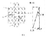
- Figure 1 is a schematic diagram of a special mold and a force analysis diagram
- thermocouple temperature measuring hole 4. groove
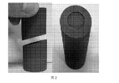
- Figure 2 is a physical diagram of a special mold
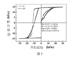
- Figure 3 is a hysteresis loop of a different gradient thermally deformed magnet
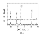
- Figure 4 is an XRD pattern of different gradient thermally deformed magnets.
- the commercial NdFeB quenching powder F powder is used, and the ⁇ 15mm cemented carbide mold is put into the mold, and the hot pressing magnet is obtained by using the optimal hot pressing temperature of the laboratory.
- the optimal heat distortion temperature and deformation amount are selected to obtain an anisotropic hot deformation magnet.
- a 0° inclination angle thermally deformable magnet is prepared by the following steps:
- the prepared commercial F powder was placed in a ⁇ 15 mm cemented carbide mold and placed in a discharge plasma sintering furnace for sintering to obtain an isotropic hot-pressed magnet.
- the specific sintering process is: heating rate 50-80 ° C / min, sintering temperature 650 ° C and holding for 3 minutes, the pressure is 300 MPa.
- the magnet obtained in the first step is taken out, and the angle of 0° is directly cut by wire cutting to obtain a desired cylinder.
- the impurities on the surface of the inclined cylinder are removed, loaded into a 0° graphite mold, and sintered by plasma sintering, and the hot-pressed magnet is deformed using a suitable temperature and pressure to obtain an anisotropic thermally deformed magnet.
- the specific sintering process is: heating rate 50-80 ° C / min, sintering temperature 700 ° C and holding for 3 minutes, the deformation is 70%, the pressure is 50MPa.
- a 5° inclination angle thermally deformable magnet is prepared by the following steps:
- the prepared commercial F powder was placed in a ⁇ 15 mm cemented carbide mold and placed in a discharge plasma sintering furnace for sintering to obtain an isotropic hot-pressed magnet.
- the specific sintering process is: heating rate 50-80 ° C / min, sintering temperature 650 ° C and holding for 3 minutes, the pressure is 300 MPa.
- the magnet obtained in the first step is taken out, and the angle of 5° is directly cut by wire cutting to obtain a desired cylinder.
- impurities on the surface of the inclined cylinder are removed, loaded into a 5° graphite mold, and sintered by plasma sintering, and the hot-pressed magnet is deformed using a suitable temperature and pressure to obtain an anisotropic thermally deformed magnet.
- the specific sintering process is: heating rate 50 ⁇ 80 ° C / min, burning The junction temperature was 700 ° C and held for 3 minutes, the deformation amount was 70%, and the pressure was 50 MPa.
- a 10° inclination angle thermally deformable magnet is prepared by the following steps:
- the prepared commercial F powder was placed in a ⁇ 15 mm cemented carbide mold and placed in a discharge plasma sintering furnace for sintering to obtain an isotropic hot-pressed magnet.
- the specific sintering process is: heating rate 50-80 ° C / min, sintering temperature 650 ° C and holding for 3 minutes, the pressure is 300 MPa.
- the magnet obtained in the first step is taken out, and the angle of 10° is directly cut by wire cutting to obtain a desired cylinder.
- impurities on the surface of the inclined cylinder are removed, loaded into a 10° graphite mold, and sintered by plasma sintering, and the hot-pressed magnet is deformed using a suitable temperature and pressure to obtain an anisotropic thermally deformed magnet.
- the specific sintering process is: heating rate 50-80 ° C / min, sintering temperature 700 ° C and holding for 3 minutes, the deformation is 70%, the pressure is 50MPa.
- a 15° inclination angle thermally deformable magnet is prepared by the following steps:
- the prepared commercial F powder was placed in a ⁇ 15 mm cemented carbide mold and placed in a discharge plasma sintering furnace for sintering to obtain an isotropic hot-pressed magnet.
- the specific sintering process is: heating rate 50-80 ° C / min, sintering temperature 650 ° C and holding for 3 minutes, the pressure is 300 MPa.
- the magnet obtained in the first step is taken out, and the angle of 15° is directly cut by wire cutting to obtain a desired cylinder.
- the third step is to remove the impurities on the surface of the inclined cylinder and load it into a 15° graphite mold for use.
- the discharge plasma is sintered, and the hot-pressed magnet is deformed using a suitable temperature and pressure to obtain an anisotropic thermally deformed magnet.
- the specific sintering process is: heating rate 50-80 ° C / min, sintering temperature 700 ° C and holding for 3 minutes, the deformation is 70%, the pressure is 50MPa.
- a 20° inclination angle thermally deformable magnet is prepared by the following steps:
- the prepared commercial F powder was placed in a ⁇ 15 mm cemented carbide mold and placed in a discharge plasma sintering furnace for sintering to obtain an isotropic hot-pressed magnet.
- the specific sintering process is: heating rate 50-80 ° C / min, sintering temperature 650 ° C and holding for 3 minutes, the pressure is 300 MPa.
- the magnet obtained in the first step is taken out, and the angle of 20° is directly cut by wire cutting to obtain a desired cylinder.
- impurities on the surface of the inclined cylinder are removed, loaded into a 20° graphite mold, and sintered by plasma plasma is used to deform the hot-pressed magnet using a suitable temperature and pressure to obtain an anisotropic thermally deformed magnet.
- the specific sintering process is: heating rate 50-80 ° C / min, sintering temperature 700 ° C and holding for 3 minutes, the deformation is 70%, the pressure is 50MPa.
- VSM VersaLab system type vibrating sample magnetometer
- Figure 4 shows the XRD pattern of the thermally deformed magnet under different shear forces.
- the ratio of I 006 /I 105 in the XRD pattern can indicate the pros and cons of the texture of the magnet. The larger the ratio, the better the texture and the more obvious the anisotropy.
- the ratio of I 006 /I 105 also increases gradually, and the anisotropy of the magnet becomes more obvious, which indicates that the addition of shear force is beneficial to the deformation of the neodymium iron boron magnet.
Landscapes
- Engineering & Computer Science (AREA)
- Manufacturing & Machinery (AREA)
- Power Engineering (AREA)
- Mechanical Engineering (AREA)
- Chemical & Material Sciences (AREA)
- Crystallography & Structural Chemistry (AREA)
- Inorganic Chemistry (AREA)
- Physics & Mathematics (AREA)
- Optics & Photonics (AREA)
- Manufacturing Cores, Coils, And Magnets (AREA)
- Powder Metallurgy (AREA)
- Hard Magnetic Materials (AREA)
Abstract
一种剪切力热变形模具和钕铁硼磁体的制备方法,属于稀土永磁领域。所述的剪切力的获得在于样品与模具接触面有一定的角度,通过调节角度的大小来控制剪切力大小。制备方法使用快淬粉装入模具使用放电等离子烧结系统(SPS),通过控制烧结条件,制备出致密的高变形量的热变形磁体。通过添加剪切力极大促进钕铁硼磁体进行变形,提高变形效率,提高磁性能。
Description
本专利发明了一种添加剪切力热变形模具和钕铁硼磁体的制备方法,属于稀土永磁领域。
1984年,日本和美国科研人员分别使用粉末冶金法和快淬法制备了具有四方结构的钕铁硼(2:14:1)永磁体,从而宣告了第三代稀土永磁材料的诞生。时至今日,钕铁硼永磁体仍是性能最好的永磁体,被誉为“磁王”。
作为第三代稀土永磁体的钕铁硼磁体具有很高的性能、高的磁能积及性价比等优点,被广泛应用在机械、信息、能源、交通等众多领域,已成为现代工业和科学技术的支撑材料之一。2015年全球高性能钕铁硼需求约5.3万吨,预计到2020年行业需求将达到9.5为万吨,复合增速为13%,超过400亿元市场规模。
最大磁能积是衡量磁性材料磁性能优劣重要指标之一。Nd2Fe14B化合物具有很强的单轴各向异性,在以Nd2Fe14B为基体的化合物永磁材料中,当Nd2Fe14B晶粒混乱取向时为各向同性,它的剩磁只有饱和磁化强度的一半即:Br=0.5Js,最大磁能积的理论值为:(BH)max=0.125(Js)2;当Nd2Fe14B晶粒有c轴规则取向时为各向异性,在理想情况下,它的剩磁接近饱和磁化强度即Jr≈Js,其最大磁能积理论值为:(BH)max=0.25(Js)2。因此,各向异性钕铁硼磁体具有更高的磁能积。
制造各向异性永磁体的方法有传统的粉末冶金法和热变形法两种方法。热变形法又包括:铸造-热变形和粉末-致密化-热变形法两种,其中粉末可以是快淬粉末、氢爆(HDDR)粉末、机械合金化粉末等。其中使用的最多的为快淬磁粉,目前快淬粉末热变形各向异性永磁体的磁性能已达到剩磁:Br=1.492T,矫顽力:Hcj=1004k A/m,最大磁能积:(BH)max=400k J/m3。热变形法已成为制造Nd-Fe-B系各向异性材料的重要工艺手段之一。
钕铁硼热变形源于塑性变形、晶界滑移以及晶界迁移组合。在热变形过程中晶体重新构成其形态,也带动改变其晶粒取向与磁畴分布。目前所有的热变形钕铁硼磁体的专利有很多如专利CN102744406A、CN104103414A、CN105869876A等,这些方法都是在正压力的情况下完成的,想获得大变形量磁体往往需要提高温度,提高温度晶粒会长大,降低磁性能。在不提高温度的情况下,想获得大变形变形量的磁体较为困难。
在镁铝合金板材轧制过程中发现,由于剪切力的存在,变形过程会更容易,极大的提高生产效率。因此,本发明设计了一种引入剪切力的新型热变形模具,并基于该模具发明了一种热变形钕铁硼磁体的制备方法,具体是使用具有一定倾斜角度的模具,在变形过程中引入一定的剪切力,从而更易于获得大变形量、优异织构和优良性能的钕铁硼磁体。
发明内容
本发明根据实验需要设计一种特殊模具,具有斜压力的石墨模
具:包括具有空腔的壳体、与工件两端面接触的上下压力模,工件两端面接触的上下压力模的端面为斜平面,斜面上有凹槽,使用时把样品放置于上下压头的凹槽内。
在钕铁硼变形过程中通过添加剪切力,更加容易获得大变形量的钕铁硼磁体,从而获得更具有优良的磁性能。本发明首先将钕铁硼粉末装入模具中,通过放电等离子烧结获得各向同性的热压磁体,把热压磁体打磨干净之后放入直径更大的模具中做变形,通过控制模具压头的倾斜角度,获得不同大小的剪切力,从而获得具有较高性能的各向异性钕铁硼磁体。
为了达到上述目的,获得具有较高性能的各向异性钕铁硼磁体的具体方法如下:
第一步,将准备好的钕铁硼快淬粉装入模具中,放入放电等离子烧结炉中,使用合适的温度、压力进行热压烧结,得到各向同性的热压磁体;
第二步,将第一步得到的磁体取出,利用线切割直接切出两端面为平行的斜面的斜柱体,斜端面与正端面之间的夹角为θ,正端面为垂直轴的端面,0°<θ<45°,优选0°<θ<20°,进一步优选θ=15°;
第三步,去除斜柱体表面的杂质,装入具有剪切力热变形模具中,使用放电等离子烧结,使用合适的温度、压力对热压磁体进行变形,得到各向异性的热变形磁体。
上述步骤一,根据快淬粉成分选择合适的温度,烧结温度一般为
550~750℃,升温速率为30~150℃/min,压力为10~500MPa,保温时间为1~10min。
上述步骤三中,变形烧结温度一般为650~850℃,升温速率为30~120℃/min,压力为10~100MPa,保温时间为1~10min。
通过调节角度的大小来控制剪切力大小,放电等离子烧结时需要采用加压烧结,压力为10~500MPa,加压方式为先预压到一定压力,然后在烧结过程中逐渐加到设定压力;卸压方式为:烧结结束,温度降至100℃后逐渐卸压。
一种具有剪切力热变形模具,其特征在于,具有斜压力,包括具有通孔空腔的外壳、与工件两端面接触的上下压力模,与工件两端面接触的上下压力模的端面为斜平面,使用时上下压力模位于外壳的空腔内,工件位于空腔内上下压力模之间。
具有剪切力热变形模具可以是石墨或硬质合金材质,壳体高度为10-150mm,可以根据需要选择最优高度。
与工件两端面接触的上下压力模的端面为斜平面,斜平面与轴垂直截面的夹角即斜面角度θ:0<θ<45°,最好为:0<θ<20°。
上下压力模的斜端面中心均设计一定高度的凹槽,凹槽直径根据工件样品的接触端面平行且匹配(工件样品的接触端面正好位于凹槽内),高度可以为0-3mm,最好为1mm;下凹槽的底面或上凹槽的顶面与各所在的斜端面平行;
模具壳体上设有测温孔(插热电偶),孔位置位于外壳外侧中间,孔深度为h:5mm<h<(d-5)mm,d为空腔直径。
获得的磁体表面打磨后进行物相分析和磁性能测试。物相分析采用X射线衍射分析仪进行物相测试,磁性能测试采用VersaLab系统型振动样品磁强计(VSM)进行。
本发明在热变形中加入横向剪切力分量,这种分作用力对组织构成的影响能对Nd-Fe-B复合纳米磁体的磁性能起到作用,更能促进钕铁硼晶体晶界滑移和晶界迁移,剪切力对变形钕铁硼磁体织构、各向异性及磁性能的有很大的促进作用,提高变形效率,提高磁性能。
以下,结合附图来详细说明本发明的实施方案,其中:
图1为特殊模具示意图及受力分析图;
1.模具外模;2.上下压力模;3热电偶测温孔;4.凹槽
图2为特殊模具实物图;
图3为不同梯度热变形磁体磁滞回线;
图4为不同梯度热变形磁体XRD图。
由于本实验室对钕铁硼变形有了大量的经验,使用商用钕铁硼快淬粉F粉,装入φ15mm的硬质合金模具,使用本实验室最优的热压温度得到热压磁体,选取最优的热变形温度及变形量进行变形得到各向异性的热变形磁体。
实施例1:
一种0°倾角热变形磁体制备,按以下步骤实施:
第一步,将准备好的商用F粉装入φ15mm的硬质合金模具中,放入放电等离子烧结炉中进行烧结,得到各向同性的热压磁体。具体烧结工艺为:升温速率50~80℃/min,烧结温度650℃并保温3分钟,压力为300MPa。
第二步,将第一步得到的磁体取出,利用线切割直接切出0°角度,得到需要的圆柱体。
第三步,去除斜柱体表面的杂质,装入0°的石墨模具中,使用放电等离子烧结,使用合适的温度压力对热压磁体进行变形,得到各向异性的热变形磁体。具体烧结工艺为:升温速率50~80℃/min,烧结温度700℃并保温3分钟,变形量为70%,压力为50MPa。
实施例2:
一种5°倾角热变形磁体制备,按以下步骤实施:
第一步,将准备好的商用F粉装入φ15mm的硬质合金模具中,放入放电等离子烧结炉中进行烧结,得到各向同性的热压磁体。具体烧结工艺为:升温速率50~80℃/min,烧结温度650℃并保温3分钟,压力为300MPa。
第二步,将第一步得到的磁体取出,利用线切割直接切出5°角度,得到需要的圆柱体。
第三步,去除斜柱体表面的杂质,装入5°的石墨模具中,使用放电等离子烧结,使用合适的温度压力对热压磁体进行变形,得到各向异性的热变形磁体。具体烧结工艺为:升温速率50~80℃/min,烧
结温度700℃并保温3分钟,变形量为70%,压力为50MPa。
实施例3:
一种10°倾角热变形磁体制备,按以下步骤实施:
第一步,将准备好的商用F粉装入φ15mm的硬质合金模具中,放入放电等离子烧结炉中进行烧结,得到各向同性的热压磁体。具体烧结工艺为:升温速率50~80℃/min,烧结温度650℃并保温3分钟,压力为300MPa。
第二步,将第一步得到的磁体取出,利用线切割直接切出10°角度,得到需要的圆柱体。
第三步,去除斜柱体表面的杂质,装入10°的石墨模具中,使用放电等离子烧结,使用合适的温度压力对热压磁体进行变形,得到各向异性的热变形磁体。具体烧结工艺为:升温速率50~80℃/min,烧结温度700℃并保温3分钟,变形量为70%,压力为50MPa。
实施例4:
一种15°倾角热变形磁体制备,按以下步骤实施:
第一步,将准备好的商用F粉装入φ15mm的硬质合金模具中,放入放电等离子烧结炉中进行烧结,得到各向同性的热压磁体。具体烧结工艺为:升温速率50~80℃/min,烧结温度650℃并保温3分钟,压力为300MPa。
第二步,将第一步得到的磁体取出,利用线切割直接切出15°角度,得到需要的圆柱体。
第三步,去除斜柱体表面的杂质,装入15°的石墨模具中,使用
放电等离子烧结,使用合适的温度压力对热压磁体进行变形,得到各向异性的热变形磁体。具体烧结工艺为:升温速率50~80℃/min,烧结温度700℃并保温3分钟,变形量为70%,压力为50MPa。
实施例5:
一种20°倾角热变形磁体制备,按以下步骤实施:
第一步,将准备好的商用F粉装入φ15mm的硬质合金模具中,放入放电等离子烧结炉中进行烧结,得到各向同性的热压磁体。具体烧结工艺为:升温速率50~80℃/min,烧结温度650℃并保温3分钟,压力为300MPa。
第二步,将第一步得到的磁体取出,利用线切割直接切出20°角度,得到需要的圆柱体。
第三步,去除斜柱体表面的杂质,装入20°的石墨模具中,使用放电等离子烧结,使用合适的温度压力对热压磁体进行变形,得到各向异性的热变形磁体。具体烧结工艺为:升温速率50~80℃/min,烧结温度700℃并保温3分钟,变形量为70%,压力为50MPa。
性能测试
使用VersaLab系统型振动样品磁强计(VSM)进行测试以上实施例制得钕铁硼热变形磁体,测试室温下磁滞回线,磁滞回线如图3所示,热压磁体性能如表1所示:
表1(Lax/Ce1-x)yFe14B磁体的磁性能

从表3可知,随着倾角度的增大,热变形磁体的磁性能逐渐增大。图4为不同剪切力下热变形磁体XRD图,XRD图中I006/I105的比值的大小可以表示磁体织构度的优劣,比值越大织构越好,各向异性就越明显,随着模具角度的逐渐增大,I006/I105的比值也逐步增大,磁体各向异性就越明显,这说明添加剪切力有利于钕铁硼磁体变形。
以上实例仅为本发明的优选实例而已,由于热压磁体较脆,在切出角度时尖端部分比较断,本专利没有给出实施例,等以后解决热压磁体断裂问题,大角度的部分还会继续实验。本专利实施例显示和描述了本发明的基本原理、主要特征以及本发明的优点,并不用于限制本发明。本行业的技术人员和科研人员应该了解,本发明可以有各种更改和变化。凡是在本发明的精神和原则范围内,任何修改等同于替换、改进等,这些变化都在本发明的保护范围内。
Claims (10)
- 一种具有剪切力热变形模具,其特征在于,具有斜压力,包括具有通孔空腔的外壳、与工件两端面接触的上下压力模,与工件两端面接触的上下压力模的端面为斜平面,使用时上下压力模位于外壳的空腔内,工件位于空腔内上下压力模之间。
- 按照权利要求1所述的一种具有剪切力热变形模具,其特征在于,具有剪切力热变形模具是石墨或硬质合金材质,外壳高度为10-150mm,根据需要选择最优高度;与工件两端面接触的上下压力模的端面为斜平面,斜平面与轴垂直截面的夹角即斜面角度θ:0<θ<45°,最好为:0<θ<20°。
- 按照权利要求1所述的一种具有剪切力热变形模具,其特征在于,上下压力模的斜端面中心均设计一定高度的凹槽,凹槽直径根据工件样品的接触端面平行且匹配,高度可以为0-3mm,最好为1mm;下凹槽的底面或上凹槽的顶面与各所在的斜端面平行。
- 按照权利要求1所述的一种具有剪切力热变形模具,其特征在于,模具壳体上设有测温孔用于插热电偶,孔位置位于外壳外侧中间,孔深度为h:5mm<h<(d-5)mm,d为空腔直径。
- 一种制备具有较高性能的各向异性钕铁硼磁体的方法,其特征在于包括以下步骤:第一步,将准备好的钕铁硼快淬粉装入模具中,放入放电等离子烧结炉中,使用合适的温度、压力进行热压烧结,得到各向同性的热压磁体;第二步,将第一步得到的磁体取出,利用线切割直接切出两端面为平行的斜面的斜柱体,斜端面与正端面之间的夹角为θ,正端面为垂直轴的端面,0°<θ<45°,优选0°<θ<20°,进一步优选θ=15°;第三步,去除斜柱体表面的杂质,装入具有剪切力热变形模具中,使用放电 等离子烧结,使用合适的温度、压力对热压磁体进行变形,得到各向异性的热变形磁体。
- 按照权利要求5的方法,其特征在于,步骤一,根据快淬粉成分选择合适的温度,烧结温度为550~750℃,升温速率为30~150℃/min,压力为10~500MPa,保温时间为1~10min。
- 按照权利要求5的方法,其特征在于,步骤三中,变形烧结温度一般为650~850℃,升温速率为30~120℃/min,压力为10~100MPa,保温时间为1~10min。
- 按照权利要求5的方法,其特征在于,通过调节角度的大小来控制剪切力大小,放电等离子烧结时需要采用加压烧结,压力为10~500MPa,加压方式为先预压到一定压力,然后在烧结过程中逐渐加到设定压力;卸压方式为:烧结结束,温度降至100℃后逐渐卸压。
- 按照权利要求5的方法,其特征在于,具有剪切力热变形模具采用权利要求1-4任一项所述的具有剪切力热变形模具。
- 按照权利要求5-9任一项方法制备得到的具有较高性能的各向异性钕铁硼磁体。
Applications Claiming Priority (2)
| Application Number | Priority Date | Filing Date | Title |
|---|---|---|---|
| CN201710558143.8 | 2017-07-10 | ||
| CN201710558143.8A CN107546025B (zh) | 2017-07-10 | 2017-07-10 | 一种剪切力热变形模具和钕铁硼磁体的制备方法 |
Publications (1)
| Publication Number | Publication Date |
|---|---|
| WO2019010824A1 true WO2019010824A1 (zh) | 2019-01-17 |
Family
ID=60970378
Family Applications (1)
| Application Number | Title | Priority Date | Filing Date |
|---|---|---|---|
| PCT/CN2017/103075 Ceased WO2019010824A1 (zh) | 2017-07-10 | 2017-09-25 | 一种剪切力热变形模具和钕铁硼磁体的制备方法 |
Country Status (2)
| Country | Link |
|---|---|
| CN (1) | CN107546025B (zh) |
| WO (1) | WO2019010824A1 (zh) |
Citations (6)
| Publication number | Priority date | Publication date | Assignee | Title |
|---|---|---|---|---|
| JPH07169632A (ja) * | 1993-12-14 | 1995-07-04 | Isuzu Motors Ltd | 異方性磁石の製造方法 |
| JP2011068975A (ja) * | 2009-09-28 | 2011-04-07 | Toyota Motor Corp | 通電焼結方法 |
| US9312057B2 (en) * | 2013-01-30 | 2016-04-12 | Arnold Magnetic Technologies Ag | Contoured-field magnets |
| CN105489364A (zh) * | 2014-10-03 | 2016-04-13 | 丰田自动车株式会社 | 稀土磁铁的制造方法 |
| CN205165867U (zh) * | 2015-10-27 | 2016-04-20 | 北京麦戈龙永磁材料有限公司 | 一种钕铁硼磁体模具 |
| CN105575575A (zh) * | 2014-10-10 | 2016-05-11 | 财团法人金属工业研究发展中心 | 钕铁硼磁石制作方法 |
Family Cites Families (6)
| Publication number | Priority date | Publication date | Assignee | Title |
|---|---|---|---|---|
| JP2956496B2 (ja) * | 1994-11-07 | 1999-10-04 | 三菱電機株式会社 | 傾斜状平板コイルの製造方法およびその巻回治具 |
| JP4765007B2 (ja) * | 1999-06-11 | 2011-09-07 | 独立行政法人物質・材料研究機構 | フェライト粒超微細化鋼厚板の製造方法 |
| CN2923292Y (zh) * | 2006-06-20 | 2007-07-18 | 宁波科田磁业有限公司 | 用于压制磁性材料粉末的四边形成型模具 |
| CN103123862B (zh) * | 2011-11-21 | 2015-09-09 | 中国科学院宁波材料技术与工程研究所 | 提高热压/热变形辐射取向钕铁硼永磁环性能及其轴向均匀性的方法 |
| CN103928204A (zh) * | 2014-04-10 | 2014-07-16 | 重庆科技学院 | 一种低稀土含量的各向异性纳米晶NdFeB致密磁体及其制备方法 |
| CN106312067B (zh) * | 2016-10-11 | 2018-03-20 | 河海大学 | 用于放电等离子体无压烧结的石墨模具 |
-
2017
- 2017-07-10 CN CN201710558143.8A patent/CN107546025B/zh active Active
- 2017-09-25 WO PCT/CN2017/103075 patent/WO2019010824A1/zh not_active Ceased
Patent Citations (6)
| Publication number | Priority date | Publication date | Assignee | Title |
|---|---|---|---|---|
| JPH07169632A (ja) * | 1993-12-14 | 1995-07-04 | Isuzu Motors Ltd | 異方性磁石の製造方法 |
| JP2011068975A (ja) * | 2009-09-28 | 2011-04-07 | Toyota Motor Corp | 通電焼結方法 |
| US9312057B2 (en) * | 2013-01-30 | 2016-04-12 | Arnold Magnetic Technologies Ag | Contoured-field magnets |
| CN105489364A (zh) * | 2014-10-03 | 2016-04-13 | 丰田自动车株式会社 | 稀土磁铁的制造方法 |
| CN105575575A (zh) * | 2014-10-10 | 2016-05-11 | 财团法人金属工业研究发展中心 | 钕铁硼磁石制作方法 |
| CN205165867U (zh) * | 2015-10-27 | 2016-04-20 | 北京麦戈龙永磁材料有限公司 | 一种钕铁硼磁体模具 |
Also Published As
| Publication number | Publication date |
|---|---|
| CN107546025A (zh) | 2018-01-05 |
| CN107546025B (zh) | 2020-10-16 |
Similar Documents
| Publication | Publication Date | Title |
|---|---|---|
| CN105489334B (zh) | 一种晶界扩散获得高磁性烧结钕铁硼的方法 | |
| Hinz et al. | Near net shape production of radially oriented NdFeB ring magnets by backward extrusion | |
| CN105321646A (zh) | 高矫顽力纳米晶热变形稀土永磁体及其制备方法 | |
| CN103123843A (zh) | 一种细晶粒各向异性致密化钕铁硼永磁体的制备方法 | |
| CN108320876B (zh) | 一种热等静压低温烧结获得高磁性烧结钕铁硼的方法 | |
| CN102403079A (zh) | 各向异性纳米晶钕铁硼永磁材料的制备方法 | |
| CN107424695A (zh) | 一种双合金纳米晶稀土永磁体及其制备方法 | |
| CN105321645A (zh) | 高矫顽力纳米晶热变形稀土永磁材料及其制备方法 | |
| CN102766835A (zh) | 一种制备高性能SmCo永磁材料的方法 | |
| JP2024504209A (ja) | 希土類永久磁石及びその製造方法 | |
| WO2017041741A1 (zh) | 一种永磁材料及其制备方法 | |
| CN101476055A (zh) | 全致密块状各向异性纳米晶SmCo5磁体的制备方法 | |
| CN101265529A (zh) | 块状纳米晶SmCo系永磁材料的制备方法 | |
| Kim et al. | Mechanical properties of (Nd, Dy)–Fe–B magnets sintered via cyclic sintering | |
| CN101178962B (zh) | 一种稀土-铁-硼烧结磁性材料的无压制备方法 | |
| CN107958760A (zh) | 一种稀土永磁材料及其制备方法 | |
| US10079091B2 (en) | Method for manufacturing sintered magnet | |
| CN103310972A (zh) | 一种高性能烧结钕铁硼磁体的制备方法 | |
| JP2011210879A (ja) | 希土類磁石の製造方法 | |
| CN103310933A (zh) | 一种高压制备烧结钕铁硼的方法 | |
| WO2018126738A1 (zh) | 一种mn-ga合金及其磁硬化方法 | |
| CN108899150B (zh) | 一种Nd-Fe-B/Sm-Co复合粘结磁体及其制备方法 | |
| CN106531385A (zh) | 一种梯度型烧结钕铁硼磁体及其制备方法 | |
| Kassen et al. | Compression molding and novel sintering treatments for alnico Type-8 permanent magnets in near-final shape with preferred orientation | |
| CN105551789A (zh) | 一种稀土永磁体的制造方法 |
Legal Events
| Date | Code | Title | Description |
|---|---|---|---|
| 121 | Ep: the epo has been informed by wipo that ep was designated in this application |
Ref document number: 17917258 Country of ref document: EP Kind code of ref document: A1 |
|
| NENP | Non-entry into the national phase |
Ref country code: DE |
|
| 122 | Ep: pct application non-entry in european phase |
Ref document number: 17917258 Country of ref document: EP Kind code of ref document: A1 |