WO2019009268A1 - バルブ装置 - Google Patents
バルブ装置 Download PDFInfo
- Publication number
- WO2019009268A1 WO2019009268A1 PCT/JP2018/025126 JP2018025126W WO2019009268A1 WO 2019009268 A1 WO2019009268 A1 WO 2019009268A1 JP 2018025126 W JP2018025126 W JP 2018025126W WO 2019009268 A1 WO2019009268 A1 WO 2019009268A1
- Authority
- WO
- WIPO (PCT)
- Prior art keywords
- valve
- valve body
- valve seat
- exhaust gas
- exhaust
- Prior art date
- Legal status (The legal status is an assumption and is not a legal conclusion. Google has not performed a legal analysis and makes no representation as to the accuracy of the status listed.)
- Ceased
Links
Images





Classifications
-
- F—MECHANICAL ENGINEERING; LIGHTING; HEATING; WEAPONS; BLASTING
- F01—MACHINES OR ENGINES IN GENERAL; ENGINE PLANTS IN GENERAL; STEAM ENGINES
- F01N—GAS-FLOW SILENCERS OR EXHAUST APPARATUS FOR MACHINES OR ENGINES IN GENERAL; GAS-FLOW SILENCERS OR EXHAUST APPARATUS FOR INTERNAL-COMBUSTION ENGINES
- F01N1/00—Silencing apparatus characterised by method of silencing
- F01N1/08—Silencing apparatus characterised by method of silencing by reducing exhaust energy by throttling or whirling
-
- F—MECHANICAL ENGINEERING; LIGHTING; HEATING; WEAPONS; BLASTING
- F01—MACHINES OR ENGINES IN GENERAL; ENGINE PLANTS IN GENERAL; STEAM ENGINES
- F01N—GAS-FLOW SILENCERS OR EXHAUST APPARATUS FOR MACHINES OR ENGINES IN GENERAL; GAS-FLOW SILENCERS OR EXHAUST APPARATUS FOR INTERNAL-COMBUSTION ENGINES
- F01N13/00—Exhaust or silencing apparatus characterised by constructional features
- F01N13/08—Other arrangements or adaptations of exhaust conduits
-
- F—MECHANICAL ENGINEERING; LIGHTING; HEATING; WEAPONS; BLASTING
- F16—ENGINEERING ELEMENTS AND UNITS; GENERAL MEASURES FOR PRODUCING AND MAINTAINING EFFECTIVE FUNCTIONING OF MACHINES OR INSTALLATIONS; THERMAL INSULATION IN GENERAL
- F16K—VALVES; TAPS; COCKS; ACTUATING-FLOATS; DEVICES FOR VENTING OR AERATING
- F16K1/00—Lift valves or globe valves, i.e. cut-off apparatus with closure members having at least a component of their opening and closing motion perpendicular to the closing faces
- F16K1/16—Lift valves or globe valves, i.e. cut-off apparatus with closure members having at least a component of their opening and closing motion perpendicular to the closing faces with pivoted closure-members
- F16K1/18—Lift valves or globe valves, i.e. cut-off apparatus with closure members having at least a component of their opening and closing motion perpendicular to the closing faces with pivoted closure-members with pivoted discs or flaps
Definitions
- the present invention relates to a valve device that opens and closes an exhaust passage in a silencer according to the exhaust pressure of exhaust gas from an engine.
- a pressure control valve disclosed in Patent Document 1 As a valve device of this type, there is, for example, a pressure control valve disclosed in Patent Document 1.
- the pressure control valve disclosed in Patent Document 1 is swingably attached to a support portion provided in an exhaust pipe via a support shaft, and has a valve body capable of opening and closing an open end, and a biasing force applied to the valve body. And an urging body for closing the open end, and when the exhaust gas pressure of the exhaust gas in the exhaust pipe becomes larger than the urging force of the urging body, the open end is opened.
- the opening degree of the valve body can be increased, and the back pressure at the high flow rate of the exhaust gas can be reduced. It aims at providing an apparatus.
- a valve device is installed in an exhaust passage in a silencer, and a valve body which opens and closes the exhaust passage according to exhaust pressure of exhaust gas, and an elastic member which biases the valve body in a closing direction. And at a valve seat with which the valve body abuts when the valve body is closed, and at a downstream end of the flow direction of the exhaust gas of the valve seat, at least the valve body when the valve body has a predetermined opening degree
- An outer cylinder covering a part of the predetermined part of The valve body has an area larger than the cross-sectional area of the gas inlet pipe provided in the valve seat, and the gas receiving surface is larger than the cross-sectional area of the gas inlet pipe when the valve body is slightly opened.
- a valve device is installed in an exhaust passage in a silencer, and a valve body that opens and closes the exhaust passage according to the exhaust pressure of exhaust gas, and an elastic member that biases the valve body in a closing direction. And at a valve seat with which the valve body abuts when the valve body is closed, and at a downstream end of the flow direction of the exhaust gas of the valve seat, at least the valve body when the valve body has a predetermined opening degree An outer cylinder covering a part of the predetermined part of The valve body is provided swingably on the valve seat via a support shaft.
- the outer cylinder is disposed on the opposite side of the support shaft with respect to the central position of the gas inlet pipe provided in the valve seat, and the first wall covering the tip edge of the valve body, and the downstream of the flow direction of the exhaust gas G
- a central portion of the side edge has a pair of second wall portions covering both side edges of the valve body projecting like an arc.
- the opening degree of the valve can be increased by providing the wall where the exhaust gas does not leak from the periphery of the exhaust passage when the valve is opened. Moreover, the back pressure at the time of high flow rate of exhaust gas can be reduced by enlarging the opening degree of a valve body.
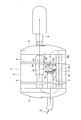
- FIG. 1 is a schematic configuration view of a silencer incorporating the valve device of the first embodiment of the present invention.
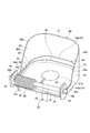
- FIG. 2 is a perspective view of the valve device as viewed from the valve body side.
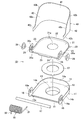
- FIG. 3 is an exploded perspective view of the valve device.
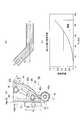
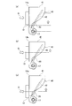
- Fig.4 (a) is a side view when the valve body of the said valve apparatus opens a predetermined angle
- FIG.4 (b) is explanatory drawing which shows the state of the flow when a valve body opens a predetermined angle
- a figure 4 (c) is a reference diagram showing the relationship between the bending angle of the circular pipe and the loss factor.
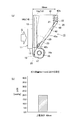
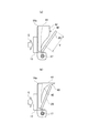
- FIG.5 (a) is a side view at the time of opening of the valve body of the said valve apparatus
- FIG.5 (b) is explanatory drawing which shows the back pressure at the time of opening of the same valve body.
- Fig.6 (a) is a side view at the time of opening of the valve body of the valve apparatus of a comparative example
- FIG.6 (b) is explanatory drawing which shows the back pressure at the time of opening of the valve body of the comparative example.
- FIG. 7 is a schematic configuration diagram of a silencer incorporating the valve device of the second embodiment of the present invention.
- FIG. 8 is an explanatory view showing the state of the gas flow rate on the surface of the valve body in the valve device of the embodiment.
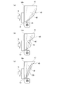
- FIG. 9 (a) is a side view in which the outer cylinder of the above embodiment covers within 3/4 of the distance between the support shaft and the upper wall from the upper wall of the valve body, and Fig. 9 (b) and 9 (c). ) Is a side view in which the same outer cylinder covers the upper part from the central position of the inlet pipe. 10 (a) to 10 (c), the side wall of the outer cylinder of the above embodiment covers a part of 3/4 of the distance between the support shaft and the upper wall from the upper wall of the valve body when viewed from the side. Side view.
- FIG. 12 is a side view of a valve device of another embodiment.
- FIG. 13 is a side view of another embodiment of the valve device.
- FIG. 1 is a schematic configuration view of a silencer incorporating the valve device according to the first embodiment of the present invention
- FIG. 2 is a perspective view of the valve device as viewed from the valve body side
- FIG. 3 is an exploded perspective view of the valve device.
- 4 (a) is a side view when the valve body of the valve device is opened by a predetermined angle
- FIG. 4 (b) is an explanatory view showing a flow state when the valve body is opened by a predetermined angle
- FIG. 5 (a) is a side view when the valve body is open
- FIG. 5 (b) is an explanatory view showing a back pressure when the valve body is open. It is.
- the valve device 10 is attached to one of the through holes 9 b of a pair of through holes 9 a and 9 b formed in a baffle plate (partition plate) 9 that divides the interior of the muffler (muffler) 1.
- a baffle plate (partition plate) 9 that divides the interior of the muffler (muffler) 1.
- the through hole 9b serving as the exhaust passage in the silencer 1 is opened and closed.
- a silencer main body (muffler main body) is constituted by a substantially cylindrical outer shell 2 and outer plates 3 and 4 closing the front and rear end openings of the outer shell 2.
- the silencer 1 is a pair of baffles in the form of an inlet pipe (exhaust pipe) 5, an outlet pipe 6, an inner pipe 7, and a plate-like member provided inside the exhaust discharge noise and the high temperature exhaust gas G generated from an engine (not shown).
- the plates (partition plates) 8 and 9 are used to muffle and cool.
- the valve device 10 includes a metal valve seat 11 fixed to the through hole 9 b of the baffle plate 9 by spot welding or the like, and a cylindrical portion serving as an exhaust passage of the valve seat 11
- the metal valve body 20 for opening and closing the gas inlet pipe 13, the torsion coil spring (elastic member) 30 for urging the valve body 20 in the closing direction, and the downstream side of the flow direction of the exhaust gas G of the valve seat 11 It comprises a metal outer cylinder 40 fixed to the end portion 14 by spot welding or the like.
- the flow direction of the exhaust gas from the upstream side to the downstream side is taken as the front-rear direction. Further, a predetermined one direction orthogonal to the front-rear direction is taken as the vertical direction.
- the valve seat 11 has a flat plate portion 12 having a substantially rectangular shape with both upper corners arced, and a cylindrical portion 13 integrally formed in a cylindrical shape at the center of the front face of the flat plate portion 12.
- the flat plate portion 12 is provided with an end portion 14 having an upper end portion 14a and side end portions 14b and 14b which are integrally bent and formed rearward from the upper end edge and both side end edges of the flat plate portion 12.
- a stopper receiving portion 15 for restricting the swinging movement of the valve body 20 is integrally bent rearward.
- a notch 15 a is formed near one side end 14 b of the stopper receiving portion 15.
- a pair of flanges 16 and 16 having an axial through hole 16a at the center thereof are integrally formed below the opposite side end portions 14b and 14b of the valve seat 11.
- a support shaft 17 penetrates between the shaft through holes 16 a of the pair of flanges 16, 16. Both ends of the support shaft 17 penetrating the respective axial through holes 16 a of the pair of flanges 16, 16 are fixed to the pair of flanges 16, 16 by welding or the like.
- the valve body 20 is formed integrally with a flat plate portion 21 having a substantially rectangular shape with both upper corner sides being arc-shaped and being bent rearward from the upper end edge and both side edges of the flat plate portion 21.
- An upper portion 22 and side portions 23 and 23 are provided.
- the inclined piece portion 24 is formed so as to be inclined rearward and bent.
- a stopper 25 which abuts against the stopper receiving portion 15 of the valve seat 11 is integrally formed.
- the angle by which the stopper 25 of the valve body 20 abuts against the stopper receiving portion 15 of the valve seat 11 to restrict the swinging angle of the valve body 20 is a predetermined opening degree of the valve body 20.
- a notch 24 a is formed on one side 23 of the inclined piece 24. Furthermore, a pair of flanges 26 and 26 having an axial through hole 26 a at the center are integrally formed below the side portions 23 and 23 of the valve body 20. A support shaft 17 for pivotably supporting the valve body 20 with respect to the valve seat 11 is penetrated through the respective shaft through holes 26 a of the pair of flanges 26, 26.
- a circular convex portion 21a is integrally formed on the front side, and heat resistance is provided around the circular convex portion 21a of the front surface of the flat plate portion 21.
- an annular plate-like buffer mat 27 is fixed by spot welding or the like.
- the torsion coil spring 30 is mounted around the support shaft 17, and one end 31 of the torsion coil spring 30 is engaged and locked to the back surface of the flat plate portion 21 of the valve body 20, and the other end 32 is a valve seat
- the notches 15 a of the stopper receiving portions 15 of 11 are engaged.
- the valve body 20 is biased in the direction of closing the valve seat 11.
- the outer cylinder 40 extends from the end portion 14 of the valve seat 11 to the downstream side in the flow direction of the exhaust gas G.
- Both side walls 42, 42 covering both side end portions 14b, 14b of the portion 14 are formed in a substantially inverted U-shaped plate shape.
- the outer cylinder 40 is fixed to the end 14 of the valve seat 11 by spot welding or the like.
- the upper wall 41 of the outer cylinder 40 has a length of, for example, 60 mm while the upper end 14a of the end 14 of the valve seat 11 is, for example, 14 mm. And has become longer.
- a central portion 42a is formed in an arc shape so as to extend from the tip end portion 42b side to the lower end portion 42c side.
- the lower end 42 c is formed so that the width in the front-rear direction is substantially the same as the width of the side end 14 b of the valve seat 11.
- the valve body 20 When the valve body 20 has a predetermined opening degree, the open wall portion of the valve body 20 which resists the biasing force of the torsion coil spring 30 in the arc-shaped central portions 42 a of the upper wall 41 and both side walls 42 and 42 of the outer cylinder 40.
- the upper part 22 and both side parts 23 and 23 are covered respectively. That is, the predetermined opening degree ( ⁇ ) of the valve body 20 is an angle at which the valve body 20 swings when the exhaust pressure of the exhaust gas G is maximum, and is set to 45 ° at the maximum.
- the valve body 20 of the valve device 10 is closed because the exhaust pressure of the exhaust gas G flowing in the silencer 1 is small at the time of low rotation of the engine.
- the valve body 20 is closed, the exhaust gas G flows in the silencer 1 as shown by the arrow R1 in FIG. 1, and in the middle route of the inner pipe 7 from the end 5a of the inlet pipe 5, the baffle plate 9
- the sound level is reduced by the hole diameter (air flow resistance) of the through hole 9a.
- the valve body 20 of the valve device 10 is a torsion coil spring. Opens against 30 elastic biases.
- the valve device 10 reduces the back pressure when the flow rate of the exhaust gas G is high, as shown in FIGS. 5 (b) and 6 (b), by reducing the loss of the entire gas flow of the exhaust gas G. can do.
- the pair of flanges 26, 26 of the valve body 20 is swingably supported via the bush 28 on the same support shaft 17 between the pair of flanges 16, 16 of the valve seat 11.
- a torsion coil spring 30 is provided to bias the valve body 20 in the closing direction. Therefore, the number of parts can be reduced, and the overall structure can be simplified.
- the stopper receiving portion 15 for restricting the swing of the valve body 20 is provided on the valve seat 11, so that the stopper 25 of the valve body 20 is the valve seat 11 as shown in FIG.
- the opening degree (swinging angle) regulated against the stopper receiving portion 15 of the above can be the maximum angle.
- FIG. 7 is a schematic block diagram of a silencer incorporating the valve device of the second embodiment of the present invention.
- the cylindrical portion of the valve seat 11 of the valve device 10 is fitted on the outer periphery of the end 5a of the inlet pipe (exhaust pipe) 5 in the silencer 1 and fixed by spot welding or the like. .
- the same operation and effect as the first embodiment can be obtained.
- torsion coil spring was used as an elastic member which urges the valve body in the closing direction
- another elastic member such as a leaf spring may be used.
- FIG. 8 is an explanatory view showing the state of the gas flow velocity on the surface of the valve body in the valve device of the embodiment.
- FIG. 9 (a) is 3/4 of the distance between the support shaft and the upper wall from the upper wall of the valve body.
- 9 (b) and (c) are side views in which the same outer cylinder covers the upper part from the center position of the cylindrical portion as the inlet pipe, and
- FIGS. 10 (a) to 10 (c) are side views 11A and 11B are side views in which the side wall of the outer cylinder covers a part of 3/4 of the distance between the support shaft and the upper wall from the upper wall of the valve body, and
- FIGS. It is a side view in which the upper wall of a pipe covers a part of 3/4 of distance of a spindle and an upper wall from the upper wall of a valve body.
- the valve body 20 has a larger area than the cross-sectional area of the cylindrical portion (gas inlet pipe) 13 provided in the valve seat 11, and the gas pressure is received when the valve body 20 is slightly opened.
- the surface (the outer surface of the flat plate portion 21) is formed larger than the cross-sectional area of the cylindrical portion 13 of the valve seat 11. Further, the central position of the cylindrical portion 13 of the valve seat 11 is on the upper wall 41 side of the outer cylinder 40 with respect to the support shaft 17 that swingably supports the valve body 20.
- the upper wall 41 of the outer cylinder 40 refers to the wall facing the support shaft 17, and the both side walls 42 and 42 of the outer cylinder 40 are located on the both sides of the support shaft 17. I say a wall.
- the valve body 20 and the walls 41 and 42 of the outer cylinder 40 are projected on arbitrary surfaces parallel to the flow direction of the exhaust gas G, covering the valve body 20 and the walls 41 and 42 of the outer wall 40 overlap Say what to do.
- the outer cylinder 40 is at least one larger in its upper part than the central position of the cylindrical portion (gas inlet pipe) 13 which becomes the exhaust passage. I tried to cover the part. Further, when the side walls 42 and 42 have at least a part shorter in the gas downstream flow direction than the upper wall 41, that is, as shown in FIGS.
- the outer cylinder when viewed from the side
- the side walls 42 and 42 of 40 cover a part of 3 ⁇ 4 of the distance between the support shaft 17 and the upper wall 41 from the upper wall 41 of the valve body 20, or FIG. 11 (a), (b)
- the upper wall 41 of the outer cylinder 40 covers a part of 3/4 of the distance between the support shaft 17 and the upper wall 41 from the upper wall 41 of the valve body when viewed from above as shown in FIG.
- the opening degree of the valve body 20 can be simply and reliably increased, and the back pressure can be reliably reduced.
- FIG. 12 is a side view of the valve device of another embodiment
- FIG. 13 is a side view of the valve device of another embodiment.
- the valve body 20 is completely covered with the rectangular plate-like side walls 42, 42 having the same width as the upper wall 41 of the outer cylinder 40, or as shown in FIG. In the same manner, the valve body 20 is covered with the same width as the upper wall 41 of the outer cylinder 40 and the side walls 42 and 42 of the trapezoidal plate-like side in which the tip side of the valve body 20 is cut like a triangular plate.
- the opening degree of the valve body 20 can be simply and reliably increased, and the back pressure can be reliably reduced.
- the opening degree of the valve can be increased by providing the wall where the exhaust gas does not leak from the periphery of the exhaust passage when the valve is opened. Moreover, the back pressure at the time of high flow rate of exhaust gas can be reduced by enlarging the opening degree of a valve body.
Landscapes
- Engineering & Computer Science (AREA)
- General Engineering & Computer Science (AREA)
- Mechanical Engineering (AREA)
- Chemical & Material Sciences (AREA)
- Combustion & Propulsion (AREA)
- Exhaust Silencers (AREA)
- Lift Valve (AREA)
Abstract
バルブ装置(10)は、消音器(1)中の排気通路(9b)に設置され、排気ガス(G)の排気圧力に応じて排気通路(9b)を開閉する弁体(20)と、弁体(20)を閉じる方向に付勢する弾性部材(30)と、弁体(20)が閉じた際に該弁体(20)が当接する弁座(11)と、弁座(11)の排気ガス(G)の流れ方向の下流側の端部(14)に設けられ、弁体(20)が所定開度である場合に少なくとも弁体(20)の所定部の一部を覆う外筒(40)とを備える。弁体(20)は、弁座(11)に設けられたガス入口管(13)の断面積よりも大きい面積を有し、弁体(20)が僅かでも開いた際にガス受圧面がガス入口管(13)の断面積よりも大きくなっている。
Description
本発明は、エンジンからの排気ガスの排気圧力に応じて消音器中の排気通路を開閉するバルブ装置に関する。
この種のバルブ装置として、例えば、特許文献1に開示された圧力制御弁がある。この特許文献1に開示された圧力制御弁は、排気管に設けた支持部に支軸を介して揺動可能に取り付けられ、開口端を開閉可能な弁体と、この弁体に付勢力を付与して開口端を閉塞させる付勢体とを備え、排気管内の排気ガスの排気圧力が付勢体の付勢力より大きくなると、開口端を開放するものである。
しかしながら、前記従来の圧力制御弁では、弁体が開くと弁体の周囲から排気ガスが逃げてしまい、弁体を大きく開くことができず、排気ガスの高流量時の背圧を低減することができなかった。
そこで、本発明は、弁体の周囲から排気ガスが逃げないようにすることで、弁体の開度を大きくすることができ、排気ガスの高流量時の背圧を低減することができるバルブ装置を提供することを目的とする。
本発明の第1態様に係るバルブ装置は、消音器中の排気通路に設置され、排気ガスの排気圧力に応じて排気通路を開閉する弁体と、弁体を閉じる方向に付勢する弾性部材と、弁体が閉じた際に該弁体が当接する弁座と、弁座の排気ガスの流れ方向の下流側の端部に設けられ、弁体が所定開度である場合に少なくとも弁体の所定部の一部を覆う外筒を備える。弁体は、弁座に設けられたガス入口管の断面積よりも大きい面積を有し、弁体が僅かでも開いた際にガス受圧面がガス入口管の断面積よりも大きくなっている。
本発明の第2態様に係るバルブ装置は、消音器中の排気通路に設置され、排気ガスの排気圧力に応じて排気通路を開閉する弁体と、弁体を閉じる方向に付勢する弾性部材と、弁体が閉じた際に該弁体が当接する弁座と、弁座の排気ガスの流れ方向の下流側の端部に設けられ、弁体が所定開度である場合に少なくとも弁体の所定部の一部を覆う外筒を備える。弁体は、弁座に支軸を介して揺動自在に設けられている。外筒は、弁座に設けられたガス入口管の中心位置に対して、支軸の反対側に配置され、弁体の先端縁を覆う第1壁部と、排気ガスGの流れ方向の下流側の端縁の中央部が円弧状に突出した弁体の両側端縁を覆う一対の第2壁部とを有する。弁体が所定開度である場合に、外筒の第1壁部と一対の第2壁部の中央部が弁体の先端縁と両側端縁をそれぞれ覆っている。
本発明の態様に係るバルブ装置によれば、弁体が開くときに、排気ガスが排気通路の周囲から漏れない壁を設けることにより、弁体の開度を大きくすることができる。また、弁体の開度を大きくすることで、排気ガスの高流量時の背圧を低減することができる。
以下、本発明の実施形態を図面に基づいて説明する。
図1は本発明の第1実施形態のバルブ装置を内蔵した消音器の概略構成図、図2は同バルブ装置を弁体側から見た斜視図、図3は同バルブ装置の分解斜視図、図4(a)は同バルブ装置の弁体が所定角度開いた場合の側面図、図4(b)は弁体が所定角度開いた場合の流れの状態を示す説明図、図4(c)は円管の曲り角度と損失係数の関係を示す参考図、図5(a)は同弁体の開時の側面図、図5(b)は同弁体の開時の背圧を示す説明図である。
図1に示すように、バルブ装置10は、消音器(マフラ)1内を仕切るバッフルプレート(仕切板)9に形成された一対の貫通孔9a,9bのうちの片方の貫通孔9bに取り付けられており、図示しないエンジンからの排気ガスGの排気圧力に応じて消音器1中の排気通路となる貫通孔9bを開閉するものである。
図1に示すように、消音器1は、略円筒状のアウタシェル2と、このアウタシェル2の前後両端開口部を閉塞するアウタプレート3,4とで消音器本体(マフラ本体)が構成されている。この消音器1は、図示しないエンジンから発生する排気吐出音と高温の排気ガスGを、内部に設けられたインレットパイプ(排気管)5とアウトレットパイプ6とインナパイプ7及び板状で一対のバッフルプレート(仕切板)8,9とによって消音、冷却するものである。
図1~図3に示すように、バルブ装置10は、バッフルプレート9の貫通孔9bにスポット溶接等により固着される金属製の弁座11と、この弁座11の排気通路となる円筒部(ガス入口管)13を開閉する金属製の弁体20と、この弁体20を閉じる方向に付勢する捩りコイルバネ(弾性部材)30と、弁座11の排気ガスGの流れ方向の下流側の端部14にスポット溶接等により固着された金属製の外筒40とで構成されている。
ここで、説明の便宜的のために、排気ガスの上流側から下流側への流れの方向を前後方向とする。また、前後方向に対して直交する所定の一方向を上下方向とする。
図2、図3に示すように、弁座11は、両上角側が円弧状で略矩形の平板部12と、この平板部12の前面中央に円筒状に一体突出形成された円筒部13と、平板部12の上端縁及び両側端縁より後方に一体に折り曲げ形成された上端部14aと側端部14b,14bとを有した端部14とを備えている。
弁座11の平板部12の下端縁には、弁体20の揺動を規制するストッパ受部15を後方に一体に折り曲げ形成してある。このストッパ受部15の一方の側端部14b寄りには切欠き部15aを形成してある。また、弁座11の両側端部14b,14bの下側には、中央に軸貫通孔16aを有した一対のフランジ16,16を一体形成してある。この一対のフランジ16,16の各軸貫通孔16a間には支軸17が貫通している。この一対のフランジ16,16の各軸貫通孔16aを貫通した支軸17の両端側は、一対のフランジ16,16に溶接等により固定されている。
図2、図3に示すように、弁体20は、両上角側が円弧状で略矩形の平板部21と、この平板部21の上端縁及び両側端縁より後方に一体に折り曲げ形成された上部22と側部23,23とを備えている。
弁体20の平板部21の下端縁には、傾斜片部24を後方に傾斜させて折り曲げ形成してある。この傾斜片部24の中央には、弁座11のストッパ受部15に当接するストッパ25を一体突出形成してある。この弁体20のストッパ25が弁座11のストッパ受部15に当接して弁体20の揺動する角度が規制されるまでの角度が弁体20の所定開度となっている。
また、傾斜片部24の一方の側部23寄りには、切欠き部24aを形成してある。さらに、弁体20の両側部23,23の下側には、中央に軸貫通孔26aを有した一対のフランジ26,26が一体形成してある。この一対のフランジ26,26の各軸貫通孔26aに弁座11に対して弁体20を揺動自在に支持する支軸17が貫通されている。
さらに、弁体20の平板部21の中央には、円形状の凸部21aを前面側に一体突出形成してあり、この平板部21の前面の円形状の凸部21aの周りには、耐熱性で円環板状の緩衝マット27をスポット溶接等により固着してある。弁体20が閉じた際に、弁体20の平板部21が緩衝マット27を介して弁座11の平板部12に隙間なく当接するようになっている。また、弁座11の一対のフランジ16,16と弁体20の一対のフランジ26,26の各間の支軸17には円環状のブッシュ28をそれぞれ貫通させている。この一対のブッシュ28,28を介して支軸17に弁体20を揺動自在に軸支してある。
図2に示すように、捩りコイルバネ30は、支軸17の回りに装着されていて、その一端31側を弁体20の平板部21の裏面に当接係止させ、他端32を弁座11のストッパ受部15の切欠き部15aに係止させている。これにより、弁座11に対して弁体20を閉じる方向に付勢している。
図2、図3に示すように、外筒40は、弁座11の端部14から、排気ガスGの流れ方向の下流側に延設されている。そして、弁座11の端部14の上端部14aを覆う上壁(天井壁)41と、排気ガスGの流れ方向の下流側端部の中央部42aが円弧状に突出した弁座11の端部14の両側端部14b,14bを覆う両側壁42,42とを備えて略逆U字板状に形成されている。この外筒40は、弁座11の端部14に点付け溶接等により固着されている。
図5(a)及び図6(a)に示すように、外筒40の上壁41は、弁座11の端部14の上端部14aが例えば長さ14mmであるのに対して、例えば60mmと長くなっている。また、外筒40の両側壁42,42は、先端部42b側から下端部42c側にかけて中央部42aが円弧状に突出形成されている。そして、下端部42cは、前後方向の幅が弁座11の側端部14bと略同じ幅になるように形成されている。
弁体20が所定開度である場合に、外筒40の上壁41と両側壁42,42の各円弧状の中央部42aが、捩りコイルバネ30の付勢力に抗した開いた弁体20の上部22と両側部23,23をそれぞれ覆うようになっている。即ち、弁体20の所定開度(θ)は、排気ガスGの排気圧力が最大であるときに弁体20が揺動する角度であり、最大45°に設定されている。これにより、弁体20が開いたときに、弁体20の周囲を外筒40で覆うことで、弁体20の開度を増加させ、低背圧化の効果が得られるようになっている。
以上実施形態のバルブ装置10によれば、エンジンの低回転時において、消音器1内を流れる排気ガスGの排気圧力が小さいため、バルブ装置10の弁体20は閉じている。この弁体20が閉じている場合、排気ガスGは、消音器1内を図1の矢印R1で示すように流れ、インレットパイプ5の端部5aからインナパイプ7の中間ルートでは、バッフルプレート9の貫通孔9aを通過し、この貫通孔9aの孔径(通気抵抗)により音レベルの低減が図られる。
また、エンジンの回転数が所定の低速回転域を超え、排気ガスGの排気圧力が捩りコイルバネ30の弾性による付勢力を超える中・高回転時においては、バルブ装置10の弁体20が捩りコイルバネ30の弾性付勢力に抗して開く。この場合、インレットパイプ5の端部5aからインナパイプ7の中間ルートでは、バッフルプレート9の貫通孔9aを通過する図1の矢印R1で示す流れと、バルブ装置10の弁座11の円筒部13(バッフルプレート9の貫通孔9b)を通過する図1の矢印R2で示す流れの2つの流れとなり、排気ガスGが流れる断面積が増え、通気抵抗が低減する。
この場合、図4(a),(b),(c)に示すように、バルブ装置10の弁体20の開度θが大きくなると、全体のガス流れの損失が減少する。開度20°でおよそ半分になり、開度45°を超えると損失低減度は低下する。即ち、弁体20を20°以上開かせると効果は大きく、45°程度まで開くと効果は薄れる。
また、図6(a)に示す弁座11の端部14を外筒40の壁で覆っていないバルブ装置10′と比較して、弁体20の開時に、弁体20の上部22と両側部23,23を覆う上壁41と両側壁42,42を有した外筒40を弁座11の端部14に設けることで、弁座11の端部14の上端部14a及び両側端部14b,14b側からの排気ガスGの漏れを防ぐことができる。このため、本実施形態のバルブ装置10では、弁体20の開度を、外筒40を設けていないバルブ装置10′よりも大きくすることができる。このように、バルブ装置10は、排気ガスGの全体のガス流れの損失減少により、図5(b)及び図6(b)に示すように、排気ガスGの高流量時の背圧を低減することができる。
また、バルブ装置10では、弁座11の一対のフランジ16,16の間の同一の支軸17に、ブッシュ28を介して弁体20の一対のフランジ26,26を揺動自在に支持すると共に、弁体20を閉じる方向に付勢する捩りコイルバネ30を介在してある。このため、部品点数を減らすことができ、全体の構造を簡素化することができる。
さらに、バルブ装置10では、弁体20の揺動を規制するストッパ受部15を弁座11に設けたことにより、図5(a)に示すように、弁体20のストッパ25が弁座11のストッパ受部15に当たって規制される開度(揺動角度)を最大角度とすることができる。
図7は本発明の第2実施形態のバルブ装置を内蔵した消音器の概略構成図である。
この第2実施形態では、消音器1中にあるインレットパイプ(排気管)5の端部5aの外周に、バルブ装置10の弁座11の円筒部を嵌め込んでスポット溶接等により固着してある。これにより、前記第1実施形態と同様の作用・効果を奏する。
尚、前記各実施形態によれば、弁体を閉じる方向に付勢する弾性部材として捩りコイルバネを用いたが、板バネ等の他の弾性部材を用いても良い。
(実施例)
図8は、実施例のバルブ装置における弁体表面のガス流速の状態を示す説明図、図9(a)は外筒が弁体の上壁から支軸と上壁との距離の3/4以内を覆う側面図、図9(b),(c)は同外筒が入口管としての円筒部の中心位置より上部を覆う側面図、図10(a)~(c)は側面から見るときに外筒の側壁が弁体の上壁から支軸と上壁との距離の3/4の一部を覆っている側面図、図11(a),(b)は上から見るときに外筒の上壁が弁体の上壁から支軸と上壁との距離の3/4の一部を覆っている側面図である。
図8は、実施例のバルブ装置における弁体表面のガス流速の状態を示す説明図、図9(a)は外筒が弁体の上壁から支軸と上壁との距離の3/4以内を覆う側面図、図9(b),(c)は同外筒が入口管としての円筒部の中心位置より上部を覆う側面図、図10(a)~(c)は側面から見るときに外筒の側壁が弁体の上壁から支軸と上壁との距離の3/4の一部を覆っている側面図、図11(a),(b)は上から見るときに外筒の上壁が弁体の上壁から支軸と上壁との距離の3/4の一部を覆っている側面図である。
図8に示すように、弁体20の上部は排気ガスGの流速が早いため、弁体20のどこか一部以上でも外筒40の上壁41や両側壁42,42の壁で覆うことで、弁開度は大きくなる。
そこで、弁体20は、弁座11に設けられた円筒部(ガス入口管)13の断面積よりも大きい面積を有したものを使用し、弁体20が僅かでも開いた際にそのガス受圧面(平板部21の外面)が弁座11の円筒部13の断面積よりも大きく形成されている。また、弁座11の円筒部13の中心位置は、弁体20を揺動自在に支持する支軸17より外筒40の上壁41側にある。さらに、外筒40が弁座11の円筒部13の中心位置より上部、または、開時の弁体20のガス受圧面面積のうち上壁41側から3/4を占める部分V、即ち、上壁41から支軸17と上壁41との距離の3/4以内のいずれか大きい方を少なくとも一部覆うようになっている。ここで、外筒40の上壁41とは、支軸17と対向する側の壁をいい、また、外筒40の両側壁42,42とは、支軸17の両端側に位置する側の壁をいう。また、覆うとは、排気ガスGの流れ方向に平行な任意の面に弁体20と外筒40の壁41,42を投影した際に、弁体20と外壁40の壁41,42が重複することをいう。
詳述すると、弁体20の開度θが所定角度(例えば45°)で、図9(a)に示すように、弁体20の上壁41から支軸17と上壁41との距離の3/4以内、または、図9(b),(c)に示すように、外筒40が排気通路となる円筒部(ガス入口管)13の中心位置より上部のいずれか大きい方を少なくとも一部覆うようにした。また、両側壁42,42に上壁41よりガス下流流れ方向に短い部分が少なくとも一部ある場合に、つまり、図10(b),(c)に示すように、側面から見るときに外筒40の両側壁42,42が弁体20の上壁41から支軸17と上壁41との距離の3/4の一部を覆うようにしたり、または、図11(a),(b)に示すように、上から見るときに外筒40の上壁41が弁体の上壁41から支軸17と上壁41との距離の3/4の一部を覆うようにしたりする場合、弁体20の開度を簡単かつ確実に増加させることができ、背圧を確実に減少させることができる。
図12は他の実施例のバルブ装置の側面図であり、図13は別の実施例のバルブ装置の側面図である。
図12に示すように、弁体20を、外筒40の上壁41と同じ幅を有する矩形板状の両側壁42,42の壁で完全に覆うようにしたり、また、図13に示すように、弁体20を、外筒40の上壁41と同じ幅で、弁体20の先端側が三角板状に切り欠かれた台形板状の両側壁42,42の壁でほぼ覆うようにしたりすることで、弁体20の開度を簡単かつ確実に増加させることができ、背圧を確実に減少させることができる。
以上、本発明の実施形態について説明したが、これらの実施形態は本発明の理解を容易にするために記載された単なる例示に過ぎず、本発明は上述した実施形態に限定されることなく、その発明の範囲内において種々の変形が可能であることはいうまでもない。
本出願は、2017年7月6日に出願された日本国特許出願第2017-132753号に基づく優先権を主張しており、この出願の全内容が参照により本願明細書に組み込まれる。
本発明の態様に係るバルブ装置によれば、弁体が開くときに、排気ガスが排気通路の周囲から漏れない壁を設けることにより、弁体の開度を大きくすることができる。また、弁体の開度を大きくすることで、排気ガスの高流量時の背圧を低減することができる。
1 消音器
5 インレットパイプ(排気管)
5a 端部
9 バッフルプレート(仕切板)
9b 貫通孔(排気通路)
10 バルブ装置
11 弁座
13 円筒部(ガス入口管)
14 排気ガスの流れ方向の下流側の端部
15 ストッパ受部
17 支軸
20 弁体
22 上部
23 側部
25 ストッパ
30 捩りコイルバネ(弾性部材)
40 外筒
41 上壁
42 側壁
42a 円弧状の中央部
G 排気ガス
θ 弁体の揺動角度(所定開度)
5 インレットパイプ(排気管)
5a 端部
9 バッフルプレート(仕切板)
9b 貫通孔(排気通路)
10 バルブ装置
11 弁座
13 円筒部(ガス入口管)
14 排気ガスの流れ方向の下流側の端部
15 ストッパ受部
17 支軸
20 弁体
22 上部
23 側部
25 ストッパ
30 捩りコイルバネ(弾性部材)
40 外筒
41 上壁
42 側壁
42a 円弧状の中央部
G 排気ガス
θ 弁体の揺動角度(所定開度)
Claims (11)
- 消音器中の排気通路に設置され、排気ガスの排気圧力に応じて前記排気通路を開閉する弁体と、
前記弁体を閉じる方向に付勢する弾性部材と、
前記弁体が閉じた際に該弁体が当接する弁座と、
前記弁座の前記排気ガスの流れ方向の下流側の端部に設けられ、前記弁体が所定開度である場合に少なくとも前記弁体の所定部の一部を覆う外筒を備え、
前記弁体は、前記弁座に設けられたガス入口管の断面積よりも大きい面積を有し、前記弁体が僅かでも開いた際にガス受圧面が前記ガス入口管の断面積よりも大きくなることを特徴とするバルブ装置。 - 請求項1記載のバルブ装置であって、
前記弁体は、前記弁座に支軸を介して揺動自在に設けられており、
前記外筒は、前記ガス入口管の中心位置に対して、前記支軸の反対側に配置され、前記弁座の端部から前記排気ガスの流れ方向の下流側に延びる第1壁部と、前記第1壁部の両側端縁のそれぞれと連続し、前記弁座の端部から前記排気ガスの流れ方向の下流側に延びる一対の第2壁部と、を備え、
前記一対の第2壁部の少なくとも一方は、前記排気ガスの流れ方向の長さが、前記第1壁部の前記排気ガスの流れ方向の長さよりも短い部分が少なくとも一部にあることを特徴とするバルブ装置。 - 請求項1記載のバルブ装置であって、
前記弁体は、前記弁座に支軸を介して揺動自在に設けられており、
前記外筒は、前記ガス入口管の中心位置に対して、前記支軸の反対側に配置され、前記弁座の端部から前記排気ガスの流れ方向の下流側に延びる第1壁部と、前記第1壁部の両側端縁のそれぞれと連続し、前記弁座の端部から前記排気ガスの流れ方向の下流側に延びる一対の第2壁部と、を備え、
前記ガス入口管の前記中心位置は、前記支軸より前記第1壁部側にあることを特徴とするバルブ装置。 - 請求項3記載のバルブ装置であって、
前記外筒が、前記弁体における前記ガス入口管の前記中心位置より第1壁部側または前記弁体が開いた際の前記弁体のガス受圧面面積のうち前記第1壁部側から3/4を占める部分、のいずれか大きい方を少なくとも一部覆うことを特徴とするバルブ装置。 - 請求項2記載のバルブ装置であって、
前記第1壁部または前記一対の第2壁部の少なくとも一方が前記弁体の一部を覆うことを特徴とするバルブ装置。 - 請求項1~5のいずれか1項に記載のバルブ装置であって、
前記消音器内を仕切る仕切板に形成された前記排気通路となる貫通孔に前記弁座を取り付けたことを特徴とするバルブ装置。 - 請求項1~5のいずれか1項に記載のバルブ装置であって、
前記消音器中にある排気管の端部に前記弁座を取り付けたことを特徴とするバルブ装置。 - 請求項2~5のいずれか1項に記載のバルブ装置であって、
前記弁座に前記支軸を介して前記弁体を揺動自在に設け、かつ、前記弁座に前記弁体の揺動を規制するストッパを設け、前記弁体の前記所定開度は、前記弁体が前記ストッパに規制されるまで揺動する角度であることを特徴とするバルブ装置。 - 請求項1に記載のバルブ装置であって、
前記弁座に支軸を介して前記弁体を揺動自在に設け、かつ、前記弁座に前記弁体の揺動を規制するストッパを設け、前記弁体の前記所定開度は、前記弁体が前記ストッパに規制されるまで揺動する角度であることを特徴とするバルブ装置。 - 請求項8または請求項9に記載のバルブ装置であって、
前記弁体の前記所定開度は、前記排気ガスの排気圧力が最大であるときに前記弁体が揺動する角度であることを特徴とするバルブ装置。 - 消音器中の排気通路に設置され、排気ガスの排気圧力に応じて前記排気通路を開閉する弁体と、
前記弁体を閉じる方向に付勢する弾性部材と、
前記弁体が閉じた際に該弁体が当接する弁座と、
前記弁座の前記排気ガスの流れ方向の下流側の端部に設けられた外筒と、を備え、
前記弁体は、前記弁座に支軸を介して揺動自在に設けられており、
前記外筒は、前記弁座に設けられたガス入口管の中心位置に対して、前記支軸の反対側に配置されて前記弁体の先端縁部を覆う第1壁部と、前記排気ガスの流れ方向の下流側の端縁の中央部が円弧状に突出した前記弁体の両側端縁を覆う一対の第2壁部とを有し、
前記弁体が所定開度である場合に、前記外筒の第1壁部と前記一対の第2壁部の前記中央部が前記弁体の前記先端縁部と両側端縁をそれぞれ覆うことを特徴とするバルブ装置。
Applications Claiming Priority (2)
| Application Number | Priority Date | Filing Date | Title |
|---|---|---|---|
| JP2017132753A JP2019015226A (ja) | 2017-07-06 | 2017-07-06 | バルブ装置 |
| JP2017-132753 | 2017-07-06 |
Publications (1)
| Publication Number | Publication Date |
|---|---|
| WO2019009268A1 true WO2019009268A1 (ja) | 2019-01-10 |
Family
ID=64949984
Family Applications (1)
| Application Number | Title | Priority Date | Filing Date |
|---|---|---|---|
| PCT/JP2018/025126 Ceased WO2019009268A1 (ja) | 2017-07-06 | 2018-07-03 | バルブ装置 |
Country Status (2)
| Country | Link |
|---|---|
| JP (1) | JP2019015226A (ja) |
| WO (1) | WO2019009268A1 (ja) |
Cited By (1)
| Publication number | Priority date | Publication date | Assignee | Title |
|---|---|---|---|---|
| WO2021240972A1 (ja) * | 2020-05-25 | 2021-12-02 | 三恵技研工業株式会社 | マフラー用バルブ及びマフラー |
Families Citing this family (1)
| Publication number | Priority date | Publication date | Assignee | Title |
|---|---|---|---|---|
| JP7420547B2 (ja) * | 2019-12-23 | 2024-01-23 | フタバ産業株式会社 | 排気管バルブ |
Citations (3)
| Publication number | Priority date | Publication date | Assignee | Title |
|---|---|---|---|---|
| JPH08200039A (ja) * | 1995-01-27 | 1996-08-06 | Honda Motor Co Ltd | 内燃機関の排気消音装置 |
| JP2005248947A (ja) * | 2004-02-03 | 2005-09-15 | Calsonic Kansei Corp | 排気制御弁 |
| JP2012241543A (ja) * | 2011-05-16 | 2012-12-10 | Honda Motor Co Ltd | 圧力制御弁 |
-
2017
- 2017-07-06 JP JP2017132753A patent/JP2019015226A/ja active Pending
-
2018
- 2018-07-03 WO PCT/JP2018/025126 patent/WO2019009268A1/ja not_active Ceased
Patent Citations (3)
| Publication number | Priority date | Publication date | Assignee | Title |
|---|---|---|---|---|
| JPH08200039A (ja) * | 1995-01-27 | 1996-08-06 | Honda Motor Co Ltd | 内燃機関の排気消音装置 |
| JP2005248947A (ja) * | 2004-02-03 | 2005-09-15 | Calsonic Kansei Corp | 排気制御弁 |
| JP2012241543A (ja) * | 2011-05-16 | 2012-12-10 | Honda Motor Co Ltd | 圧力制御弁 |
Cited By (3)
| Publication number | Priority date | Publication date | Assignee | Title |
|---|---|---|---|---|
| WO2021240972A1 (ja) * | 2020-05-25 | 2021-12-02 | 三恵技研工業株式会社 | マフラー用バルブ及びマフラー |
| JP2021188516A (ja) * | 2020-05-25 | 2021-12-13 | 三恵技研工業株式会社 | マフラー用バルブ及びマフラー |
| JP7296688B2 (ja) | 2020-05-25 | 2023-06-23 | 三恵技研工業株式会社 | マフラー用バルブ及びマフラー |
Also Published As
| Publication number | Publication date |
|---|---|
| JP2019015226A (ja) | 2019-01-31 |
Similar Documents
| Publication | Publication Date | Title |
|---|---|---|
| US10180092B2 (en) | Flutter dampened exhaust valve | |
| US6065564A (en) | Valve apparatus for muffler | |
| US20070107981A1 (en) | Exhaust silencer | |
| US10598059B2 (en) | Slotted snap-action valve assembly for exhaust system | |
| US20090126356A1 (en) | Offset passive valve for vehicle exhaust system | |
| US10041388B2 (en) | Exhaust valve for muffler and muffler including the same | |
| US20180051610A1 (en) | Alignment System for Slotted Snap-Action Valve Assembly for Exhaust System | |
| JP2010521615A (ja) | 排気システム用スナップ作動弁 | |
| JPWO2013183772A1 (ja) | マフラー | |
| KR101883589B1 (ko) | 비틀림 댐핑을 동반하는 배기 시스템 스프링 | |
| JP2019019787A (ja) | 排気バルブ装置 | |
| JP7311542B2 (ja) | 排気部品 | |
| JP2019015226A (ja) | バルブ装置 | |
| WO2019017437A1 (ja) | 排気バルブ装置 | |
| KR101935523B1 (ko) | 머플러용 가변형 배기밸브장치 | |
| JP2006009667A (ja) | 消音器用排圧感応型制御バルブ | |
| JP6675246B2 (ja) | バタフライバルブ構造 | |
| JP2019049240A (ja) | 排気バルブ装置 | |
| KR101760504B1 (ko) | 게이트와 스프링이 일체 형성된 가변형 배기밸브 | |
| JP2012180805A (ja) | 排気系用開閉バルブ | |
| JP7520079B2 (ja) | 消音器 | |
| JP6905165B2 (ja) | 消音器のバルブ装置 | |
| JP2006249936A (ja) | 消音器における排気制御弁構造 | |
| JP4612233B2 (ja) | 内燃機関用マフラ | |
| JPH09250328A (ja) | 自動車用排気消音装置 |
Legal Events
| Date | Code | Title | Description |
|---|---|---|---|
| 121 | Ep: the epo has been informed by wipo that ep was designated in this application |
Ref document number: 18828848 Country of ref document: EP Kind code of ref document: A1 |
|
| NENP | Non-entry into the national phase |
Ref country code: DE |
|
| 122 | Ep: pct application non-entry in european phase |
Ref document number: 18828848 Country of ref document: EP Kind code of ref document: A1 |