WO2019008909A1 - リニアモータシステム及びそれを有する圧縮機 - Google Patents
リニアモータシステム及びそれを有する圧縮機 Download PDFInfo
- Publication number
- WO2019008909A1 WO2019008909A1 PCT/JP2018/018678 JP2018018678W WO2019008909A1 WO 2019008909 A1 WO2019008909 A1 WO 2019008909A1 JP 2018018678 W JP2018018678 W JP 2018018678W WO 2019008909 A1 WO2019008909 A1 WO 2019008909A1
- Authority
- WO
- WIPO (PCT)
- Prior art keywords
- command value
- voltage
- linear motor
- field element
- voltage command
- Prior art date
- Legal status (The legal status is an assumption and is not a legal conclusion. Google has not performed a legal analysis and makes no representation as to the accuracy of the status listed.)
- Ceased
Links
Images





Classifications
-
- F—MECHANICAL ENGINEERING; LIGHTING; HEATING; WEAPONS; BLASTING
- F04—POSITIVE - DISPLACEMENT MACHINES FOR LIQUIDS; PUMPS FOR LIQUIDS OR ELASTIC FLUIDS
- F04B—POSITIVE-DISPLACEMENT MACHINES FOR LIQUIDS; PUMPS
- F04B35/00—Piston pumps specially adapted for elastic fluids and characterised by the driving means to their working members, or by combination with, or adaptation to, specific driving engines or motors, not otherwise provided for
- F04B35/04—Piston pumps specially adapted for elastic fluids and characterised by the driving means to their working members, or by combination with, or adaptation to, specific driving engines or motors, not otherwise provided for the means being electric
-
- H—ELECTRICITY
- H02—GENERATION; CONVERSION OR DISTRIBUTION OF ELECTRIC POWER
- H02K—DYNAMO-ELECTRIC MACHINES
- H02K41/00—Propulsion systems in which a rigid body is moved along a path due to dynamo-electric interaction between the body and a magnetic field travelling along the path
- H02K41/02—Linear motors; Sectional motors
- H02K41/03—Synchronous motors; Motors moving step by step; Reluctance motors
-
- H—ELECTRICITY
- H02—GENERATION; CONVERSION OR DISTRIBUTION OF ELECTRIC POWER
- H02P—CONTROL OR REGULATION OF ELECTRIC MOTORS, ELECTRIC GENERATORS OR DYNAMO-ELECTRIC CONVERTERS; CONTROLLING TRANSFORMERS, REACTORS OR CHOKE COILS
- H02P25/00—Arrangements or methods for the control of AC motors characterised by the kind of AC motor or by structural details
- H02P25/02—Arrangements or methods for the control of AC motors characterised by the kind of AC motor or by structural details characterised by the kind of motor
- H02P25/06—Linear motors
- H02P25/064—Linear motors of the synchronous type
Definitions
- the present invention relates to a linear motor system and a compressor having the same.
- Patent Document 1 discloses a motor drive device for controlling a linear vibration motor, the motor drive device has a motor driver, and the motor driver performs the arithmetic processing for calculating a thrust constant. Described is a configuration having a control unit that switches between a thrust constant calculation mode (non-operation mode) for applying a DC voltage to the motor and an operation mode for applying an AC voltage to the linear vibration motor so that normal operation of the linear vibration motor is performed. It is done.
- a thrust constant calculation mode non-operation mode
- the motor drive device includes a thrust detection unit for obtaining a thrust detection value at the time of DC voltage application used for calculation of thrust constant, and detection of the thrust of the mover is performed by the mover or the mover. It is disclosed that the detection is performed by a sensor such as a pressure sensor or a strain gauge attached to the contact portion.
- Patent Document 1 since the detection of the thrust required to calculate the thrust constant of the linear vibration motor is performed by a sensor such as a pressure sensor or a strain gauge provided in the linear vibration motor, the wiring is Not only is it complicated, it may lead to an increase in size of the device. Moreover, the reactive current is suppressed by applying a voltage according to the induced voltage of the linear vibration motor, and no consideration is given to driving the linear motor with high efficiency. Therefore, the present invention has a linear motor system capable of driving the linear motor with high efficiency by suppressing the reactive current flowing in the winding without arranging a sensor for detecting the thrust of the linear motor in the linear motor, and the linear motor system Provide a compressor.
- a linear motor system at least includes an armature having a magnetic body wound with a winding, a field element having a permanent magnet, the armature or the field element And the relative position of the field element and the armature is varied according to the deformation of the elastic body, so that the field element and the armature are relatively moved in the axial direction.
- the controller includes: a linear motor for reciprocating movement; and a control unit for applying a voltage to the winding, wherein the control unit varies the relative position of the armature and the field element in the voltage applied to the winding.
- the absolute value of the voltage component to be applied is reduced at the relative position where the change rate of the magnetic flux is small, based on the change rate of the magnetic flux generated by Further, in the linear motor system according to the present invention, at least an armature having a magnetic body in which a winding is wound, a field element having a permanent magnet, and an elasticity connected to the armature or the field element.
- a linear motor that relatively reciprocates the field element and the armature in the axial direction by changing the relative position of the field element and the armature according to the deformation of the elastic body.
- the compressor according to the present invention is at least an armature having a magnetic body in which a winding is wound, a field element having a permanent magnet, and an elastic body connected to the armature or the field element.
- a linear motor that causes the field element and the armature to reciprocate relatively in the axial direction by changing the relative position of the field element and the armature according to the deformation of the elastic body.
- a control unit for applying a voltage to the winding wherein the piston connected to the field element reciprocates in the cylinder to compress the working fluid, and the control unit is a compressor.
- the absolute value of the voltage component to be applied is the relative position at which the change rate of the magnetic flux is small, based on the change rate of the magnetic flux generated by the change in relative position of the armature and the field element. To make it smaller.
- the linear motor system capable of driving the linear motor with high efficiency by suppressing the reactive current flowing in the winding without arranging a sensor for detecting the thrust of the linear motor in the linear motor and the same It becomes possible to provide a compressor. Problems, configurations, and effects other than those described above will be apparent from the description of the embodiments below.
- Example 1 It is a whole schematic block diagram of the linear motor system of Example 1 which concerns on one Example of this invention. It is a perspective view of the example of composition of an armature. It is a figure which shows the example of the change of the armature interlinkage magnetic flux with respect to a mover (field element) position. It is a schematic diagram which shows the longitudinal cross section of a magnetic pole, and the flow of magnetic flux. It is explanatory drawing of the polarity generate
- FIG. 7 is an entire schematic configuration diagram of a linear motor system of a second embodiment.
- FIG. 22 is an explanatory view showing a configuration example of a load current detector which constitutes the control unit shown in FIG. 21. It is explanatory drawing which shows the other structural example of the load current detector which comprises the control part shown in FIG. FIG. 22 is an explanatory view showing a configuration example of a voltage command value creation unit that configures the control unit shown in FIG. 21. It is a vector diagram which shows the vector sum in the voltage command value creator at the time of light load and heavy load. It is explanatory drawing which shows the other structural example of the voltage command value creation part which comprises the control part shown in FIG.
- FIG. 32 is a schematic view of a vehicle equipped with the air suspension system shown in FIG. 31.
- FIG. 18 is an explanatory view showing a configuration example of an end induction voltage regulator that constitutes the voltage command value creation device of the fourth embodiment.
- the terms “front-rear direction, left-right direction, and up-down direction orthogonal to each other” are used, but the gravity direction does not have to be parallel to the lower direction. It can be parallel to one direction or the other.
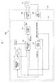
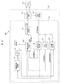
- FIG. 1 is an overall schematic configuration view of a linear motor system 100 according to a first embodiment of the present invention.
- the linear motor system 100 includes a linear motor drive device 101 and a linear motor 104. As described later, the linear motor 104 has an armature 9 and a mover 6 which move relative to each other.
- the linear motor drive device 101 includes a position detector 106, a control unit 102, and a power conversion circuit 105.
- the position detector 106 detects the relative position (movable element position) of the movable element 6 with respect to the armature 9.
- the mover (field element) 6 moves in the vertical direction, but the armature 9 and the mover (field element) 6 may move relative to each other, and the armature 9 moves in the vertical direction. But it is good. Further, the armature 9 and the mover (field element) 6 may be configured to reciprocate along the vertical direction (axial direction) at different speeds. In any case, it is preferable to connect one end of a resonant spring (assist spring) 23 to an object moving along the vertical direction (axial direction). In the following, the case where the mover (field element) 6 reciprocates in the vertical direction will be described as an example, but the direction of the reciprocation is not limited to the vertical direction.
- control unit 102 outputs an output voltage command value to power conversion circuit 105 or a drive signal (pulse signal) for driving power conversion circuit 105 in accordance with the detection result of position detector 106.
- the power conversion circuit 105 is an example of a power conversion unit that converts the voltage of the DC voltage source 120 (FIG. 19) and outputs an AC voltage.
- a direct current source may be used instead of the direct current voltage source 120.
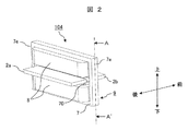
- FIG. 2 is a perspective view of the linear motor 104 (a perspective view of a configuration example of an armature).
- the linear motor 104 of the present embodiment has a mover 6 which can move relative to the armature 9 in the direction (longitudinal direction) in which the permanent magnets 2 (2a, 2b) are arranged.
- the armature 9 has two magnetic poles 7 opposed in the vertical direction via an air gap, and a winding 8 wound around the magnetic poles 7.
- the mover 6 is disposed in this air gap.
- the magnetic pole 7 has magnetic pole teeth 70 (also referred to as teeth) as end surfaces facing the mover 6.
- the armature 9 can apply a force in the front-rear direction (hereinafter referred to as thrust) to the mover 6.
- thrust can be controlled so that the mover 6 reciprocates in the front-rear direction.
- the mover 6 has two flat permanent magnets 2 (2a, 2b) magnetized in the vertical direction.
- the rear permanent magnet 2a and the front permanent magnet 2b are magnetized in opposite directions.
- the rear permanent magnet 2a has an N pole on the upper side
- the front permanent magnet 2b has an S pole on the upper side.
- the permanent magnets 2 a and 2 b are illustrated, but the mover 6 is not illustrated.
- the control unit 102 outputs a drive signal so that the mover 6 reciprocates in a range in which the permanent magnets 2 a and 2 b face the armature 9.
- FIG. 3 is a view showing an example of a change in armature linkage flux with respect to the position of the mover (field element).
- the horizontal axis represents mover (field element) position (m), and the vertical axis represents magnetic flux (Wb).
- the magnetic flux (Wb) is a flux linkage when no current flows in the winding. Indicates a change in A voltage corresponding to the time derivative of the magnetic flux is induced in the winding 8, and this voltage is generally referred to as an induced voltage, a back electromotive voltage, a speed electromotive voltage or the like. Even the same motor changes according to the speed of the mover, and for example, when the speed of the mover is high, the induced voltage becomes high.
- the induced voltage constant Ke can be regarded as constant in the section of (1) shown in FIG. In this case, the induced voltage can be calculated by multiplying the induced voltage constant Ke by the speed of the mover.
- the induced voltage constant Ke has characteristics dependent on the mover position. That is, in the linear motor having the characteristics as shown in FIG. 3, there is a problem that it becomes difficult to calculate the induced voltage when the position of the mover (field element) reciprocates away from the center.
- the maximum or minimum position of the mover position is not necessarily constant, so even if the instantaneous velocity of the mover is the same, the induced voltage changes depending on the position of the mover.
- the current flowing through the linear motor is determined by the relationship between the voltage applied to the linear motor and the induced voltage. Therefore, if the induced voltage can not be calculated correctly, the current unnecessarily increases due to excessive applied voltage, which causes a problem that the efficiency of the linear motor decreases. This causes a problem that the efficiency of the circuit driving the linear motor is also reduced. If the efficiency of the drive circuit is reduced, the amount of heat generation is increased accordingly, so the area of the radiation fin needs to be increased, and the system becomes larger.
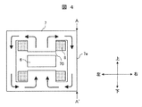
- FIG. 4 is a cross-sectional view taken along a line A-A 'of FIG. 2 (A-A' cross-sectional view).
- the magnetic pole 7 and the yoke 7e are integrally formed of, for example, a magnetic substance such as iron, and constitute a magnetic circuit.
- Arrow lines in FIG. 4 indicate an example of magnetic flux lines when current flows through the two windings 8. The direction of flow of the magnetic flux can be reversed depending on the direction of the current flowing through the winding 8 and thus is not limited to the illustrated one.
- the magnetic pole teeth 70 are magnetized by the magnetic flux lines.
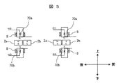
- FIG. 5 is a diagram for explaining the thrust that the mover 6 receives due to the magnetization of the magnetic pole teeth 70.
- the polarities of the magnetic pole teeth 70 generated by the current flowing through the winding 8 are represented by "N" and "S” attached near the magnetic pole teeth 70 in the figure.
- the white arrows indicate the direction of the current flowing through the winding 8.
- the mover 6 is forced forward by magnetizing the upper magnetic pole teeth 70a to "S” and the lower magnetic pole teeth 70b to "N” by the current flowing through the winding 8
- An example is shown in which the mover 6 has moved forward.
- the current flowing through the winding 8 magnetizes the upper magnetic pole teeth 70a to "N” and the lower magnetic pole teeth 70b to "S", thereby moving the mover 6 backward in force.
- An example is shown in which the mover 6 moves backward.
- magnetic flux can be supplied to the magnetic circuit including the two magnetic poles 7 to magnetize the two opposing magnetic pole teeth 70 (magnetic pole tooth set).
- an alternating voltage or current such as a sine wave or a rectangular wave (square wave) as the voltage or current, it is possible to give a thrust for reciprocating the mover 6. Thereby, the motion of the mover 6 can be controlled.
- the thrust applied to the mover 6 can be changed by changing the amplitude of the applied alternating current or alternating voltage.
- the displacement of the mover 6 can be changed as desired by appropriately changing the thrust applied to the mover 6 using a known method.
- the mover 6 reciprocates (e.g., a motion generated in the mover 6 by sequentially repeating magnetization of the magnetic pole teeth 70 as shown in the left and right views of FIG. 5), it changes in an alternating waveform.
- the amount of change in displacement of the mover 6 is referred to as a stroke.
- the magnetic pole teeth 70 are magnetic members, a magnetic attraction force for attracting the permanent magnet 2 acts.
- the two magnetic pole teeth 70 are disposed to face each other with a space between them so as to sandwich the mover 6, the total force of the magnetic attraction force acting on the mover 6 can be reduced.
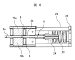
- FIG. 6 is an explanatory view of an external mechanism connected to the mover 6.
- an external mechanism constituted by a resonance spring 23 (assist spring) which is a coil spring is connected to one end of the mover 6, and its spring force It is a figure explaining the mechanism by which the needle
- One end of the resonant spring 23 is connected to the mover 6 via the intermediate portion 24, and the other end is fixed to the base 25.
- a side portion 26 which extends substantially in parallel with the extending direction of the resonant spring 23 and guides or supports the resonant spring 23 is provided.
- the mover (field element) 6 is configured as a mover (field element) moving type that moves in the vertical direction, but instead of the mover 6, an elastic body is connected to the armature 9
- the armature 9 may be configured as an armature movement type that moves the armature 9 in the vertical direction.
- FIG. 7 is an explanatory view of the relationship between the drive frequency and the stroke, showing the relationship between the drive frequency of the AC voltage on the horizontal axis and the stroke of the mover 6 on the vertical axis.
- the amplitude of the AC voltage at each drive frequency is the same.
- the stroke of the mover 6 becomes steep and large near the resonance frequency, and the stroke becomes smaller as it goes away from the resonance frequency.
- the resonant frequency is given by the square root of the value obtained by dividing the spring constant k of the resonant spring 23 by the mass m of the mover 6, but depending on the system of the linear motor 104, this value is an approximate value.
- oscillation can be performed with a large stroke (large energy). That is, when controlling the linear motor 104 in which an elastic body such as the resonance spring 23 is added to the mover 6, it is important to detect or estimate the resonance frequency of the mover 6. Even when the stroke of the mover 6 is controlled as desired, it is important to detect or estimate the resonance frequency of the mover 6.
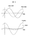
- FIG. 8 is an explanatory view of the phase relationship between the position of the mover and the velocity of the mover, and the phase relationship between the applied voltage and the motor current.
- the upper diagram of FIG. 8 shows the time change of the position and velocity of the mover 6
- the lower diagram of FIG. 8 shows the relationship between the applied voltage waveform and the time change of the current flowing through the linear motor 104.
- the upper and lower diagrams in FIG. 8 are waveforms at the same timing.
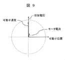
- FIG. 9 is a diagram showing the AC waveform of FIG. 8 as a vector.
- the velocity of the mover 6 is a time derivative of displacement, it changes like a cosine wave. Therefore, they can be shown as vectors on two orthogonal axes. From FIGS. 8 and 9, it can be seen that the speed of the mover 6, the applied voltage, and the motor current are substantially in phase.
- the resonance spring 23 is added to the mover 6 and the mover 6 is reciprocated at the mechanical resonance frequency determined by the mass of the mover 6 and the spring constant, the phase of the position of the mover 6 is the winding 8
- the resonance spring 23 is added to the mover 6 and the mover 6 is reciprocated at the mechanical resonance frequency determined by the mass of the mover 6 and the spring constant
- the phase of the position of the mover 6 is the winding 8
- the phase relationship of the applied voltage Vm to the winding 8, the motor current Im, and the speed of the mover 6 is Since the phase difference is not necessarily 90 degrees, it is desirable to include a control unit that changes according to conditions. At this time, in particular, it is desirable to consider the change in motor current Im due to the change in load. If the mass of the mover 6 deviates from the assumption due to manufacturing variations, or if the mass connected to the resonant spring 23 changes due to the load element added to the mover 6, the resonance frequency changes. In addition, in the case where the load element added to the mover 6 has position dependency, the resonance frequency changes during driving.
- control unit 102 adjusts the drive frequency command value ⁇ * so that the phase difference dlt ⁇ , which is the output of the phase difference detector 130 and the phase difference detector 130, follows the phase difference command value.
- frequency regulator 131, an integrator 140, the voltage command value generator 103 outputs a voltage command value Vm *, and, by comparing the voltage command value Vm * and the triangular wave carrier signal, driving the power conversion circuit 105 which outputs a voltage And a PWM signal generator 134 for outputting a drive signal.
- the control unit 102 inputs the position detection value xm of the mover (field element) by the position detector 106.
- the position detector 106 for example, a laser displacement gauge or the like is used.
- the mover (field element) position detection value xm input to the control unit 102 is input to the phase difference detector 130 that constitutes the control unit 102.
- the phase difference detector 130 outputs a phase difference dlt ⁇ between a reference phase ⁇ * , which is a phase command value described later in detail, and the mover (field element) position detection value xm.
- the phase difference dlt ⁇ output from the phase difference detector 130 is input to the drive frequency adjuster 131.
- the drive frequency adjuster 131 outputs a frequency command value ⁇ * based on the input phase difference dlt ⁇ .
- An applied voltage Vm based on the frequency command value ⁇ * is output to the linear motor 104.
- the mover (field element) position xm is an AC waveform, and the difference between the maximum displacement and the minimum displacement is a stroke.
- the absolute values of the maximum displacement and the minimum displacement may differ, and in this case, the center where the elastic forces of the elastic bodies are balanced is taken as a reference (zero).
- the absolute value of the negative maximum displacement is referred to as the negative stroke. That is, the addition of the positive side stroke and the negative side stroke is a stroke.
- the positive side stroke and the negative side stroke may differ depending on the driving conditions.
- the reference phase ⁇ * which is the phase command value of this embodiment, is obtained by integrating the drive frequency command value ⁇ * that is the output of the drive frequency regulator 131 shown in FIG. 1 by the integrator 140 as a reference phase generator. . That is, the reference phase theta * applied voltage Vm ( ⁇ *) is the phase theta * at each time of the wave having a driving frequency command value omega * corresponding to the target frequency.
- reference the phase theta * as is used driving frequency command value of the drive frequency regulator 131 omega * may be fixed to the mechanical resonance frequency of the vibration body including the movable member 6 in the present embodiment.
- the reference phase ⁇ * is a sawtooth wave having, for example, [- ⁇ , ⁇ ], [0, 2 ⁇ ], or a range wider than this for each time while the drive frequency command value ⁇ * is constant. Alternatively, it may increase linearly with time. As described later, when the drive frequency command value ⁇ * changes, the shape of the sawtooth wave or the linear increase changes accordingly (the slope changes).
- ⁇ Phase difference detector 130> When the mover 6 reciprocates, the position xm and velocity of the mover 6 and the motor current Im have a periodic function. Since the periodic function can be expressed by a Fourier series, when the position xm of the mover 6 is expressed using a Fourier transform equation, it can be defined as the following equation (1).
- x 0 is a direct current offset value
- a n and b n are n-th order Fourier coefficients, which are obtained by the following equations (2) and (3).
- T 0 is the period of the fundamental wave (the period in which the mover 6 reciprocates), that is, the reciprocal of the primary frequency (drive frequency).
- a so-called spring-mass system in which a resonant spring 23 is added to the mover 6, a mechanical resonance frequency determined from the mass of the mover 6 and the spring constant is a dominant component. Therefore, one should pay attention to the fundamental wave.
- the position xm of the mover 6 with respect to the sinusoidal applied voltage Vm can be determined by the following equation (4).
- the integration range is ⁇ 2 ⁇ to 0. This is because when the phase difference detector 130 is realized by a semiconductor integrated circuit or the like such as a microcomputer or a DSP (Digital Signal Processor), only past information can be acquired.
- a semiconductor integrated circuit or the like such as a microcomputer or a DSP (Digital Signal Processor)
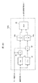
- FIG. 10 is an explanatory view showing a configuration example of the phase difference detector 130 constituting the control unit 102 shown in FIG. 1, and an explanatory view in the case where the equation (4) is shown in a block diagram.
- a reference phase ⁇ * which is a phase command value, is input to each of a sine calculator 81 that outputs the sine of the input value and a cosine calculator 82 that outputs the cosine of the input value, with respect to the reference phase ⁇ * (phase command value).
- Get sine and cosine A value obtained by multiplying each of the sine and cosine by the mover position xm is output from the multiplier 92.
- the outputs are integrated by integrators 94a and 94b, respectively, to obtain first-order Fourier coefficients of sine and cosine respectively. That is, since the frequency components higher than the drive frequency ⁇ of the Fourier expansion can be eliminated, the configuration can be robust against high-order noise.
- the outputs of the integrators 94a and 94b are input to the inverse tangent unit 86.
- the arctangent device 86 outputs an arctangent value based on the input sine and cosine components.
- the inverse tangent unit 86 of this embodiment outputs the inverse tangent value of the phase with the numerator as the output of the integrator 94a and the denominator as the output of the integrator 94b, but even if the numerator and the denominator are inverted, good.
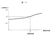
- FIG. 11 is an explanatory diagram of the relationship between the drive frequency and the output from the phase difference detector 130. As shown in FIG. That is, it is a figure which shows the relationship between the drive frequency (horizontal axis) of an alternating voltage, and the output value (phase difference dlt (theta) pos ⁇ ) (vertical axis
- the value output from the inverse tangent device 86 is larger than 0 ° when the drive frequency is higher than the resonant frequency, and smaller than 0 ° when the drive frequency is lower than the resonant frequency.
- the position xm of the movable element 6 input AC signal to the phase difference detector 130 with respect to the reference phase theta * can obtain the phase difference dlt ⁇ with respect to the reference phase theta * a primary frequency component of the , It becomes possible to estimate the resonance frequency. Then, for example, when the phase difference dlt ⁇ is more than 0 °, control is performed so that the phase difference dlt ⁇ decreases, and when less than 0 °, control may be performed so as to increase. It is preferable to control the phase difference dlt ⁇ when the reference phase ⁇ * and the fundamental frequency ⁇ have the same value as the target value dlt ⁇ * .
- an incomplete integrator can be used instead of the integrators 94a and 94b.
- the incomplete integrator is a type of low pass filter (low pass filter) and can be configured the same as the first order delay filter.
- the low pass filter may be configured with another known configuration such as a second order lag filter, not limited to the first order lag filter.
- a high pass filter (not shown) may be provided in front of the integrators 94a and 94b (or the incomplete integrators) instead of or in addition to the incomplete integrators.
- the cutoff frequency of the high pass filter can be, for example, 10 Hz or 5 Hz or less.
- the phase difference detector 130 determines the phase ⁇ of the position xm of the mover 6 with respect to the AC voltage command value V * using the inverse tangent of the ratio of the first-order Fourier coefficients of the drive frequency components, the phase difference It has high sensitivity only to the primary frequency component of the position xm of the mover 6, which is an input AC signal to the detector 130. That is, for example, even when DC offset or high-order noise is superimposed on the position xm of the mover 6, the position xm of the mover 6, which is an AC signal input to the phase difference detector 130 with respect to the reference phase ⁇ * .
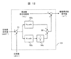
- FIG. 12 is an explanatory view showing a configuration example of the drive frequency adjuster 131 which constitutes the control unit 102 shown in FIG.
- the drive frequency adjuster 131 obtains the difference between the phase difference command value dlt ⁇ * (for example, 0 °) and the phase difference dlt ⁇ determined by the phase difference detector 130 by the subtractor 91, and the multiplier 92b obtains the proportional gain Kp_adtr.
- the result of the proportional control is multiplied by the integral gain Ki_adtr by the multiplier 92c, and the result of the integral control integrated by the integrator 94c is added by the adder 90, and the addition result is further added to the initial frequency command.
- the driving frequency command value ⁇ * is output by adding the value ( ⁇ 0 ).
- the frequency command initial value ( ⁇ 0 ) may be obtained from an upper controller (not shown), or may be set to, for example, 0 ° in advance.
- the drive frequency adjuster 131 of the present embodiment is a configuration of proportional integral control, other control configurations such as proportional control and integral control can also be applied.
- phase difference detector 130 and the drive frequency adjuster 131 in the case where the linear motor 104 is driven at a mechanical resonance frequency determined from the mass of the mover 6 and the spring constant will be described.
- the actual resonance frequency is lower than the design value. That is, when the initial value of the drive frequency is determined using the mass design value of the mover 6 (when the initial value of the drive frequency command value ⁇ * is determined using the design value), based on the actual resonance frequency Will also drive at a high frequency.
- the phase difference dlt ⁇ obtained by the phase difference detector 130 is a value larger than the phase difference command value dlt ⁇ * .
- the drive frequency adjuster 131 executes control to decrease the drive frequency command value ⁇ *, and as a result, the drive frequency command value ⁇ * matches the actual resonance frequency. Therefore, the speed energy of the mover 6 can be effectively used, and the linear motor 104 can be driven with high efficiency.
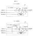
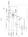
- FIG. 13 is an explanatory view showing a configuration example of the voltage command value creation unit 103 configuring the control unit 102 shown in FIG.
- Voltage command value generator 103 generates voltage command value V m2 * corresponding to the induced voltage generated according to the speed of mover 6.
- the upper diagram of FIG. 13 is a so-called open command type configuration example without the stroke controller.
- the voltage command value generator 103 includes a cosine calculator 82b, multipliers 92d to 92f, and an end induction voltage regulator 133.
- Voltage command value creation unit 103 sets a stroke command value l * which is set in advance or obtained from a host controller (not shown) or the like, and a drive frequency command value ⁇ * which is an output of drive frequency regulator 131 .
- the reference phase ⁇ * which is the output of the integrator 140 as a reference phase generator, and the mover position xm which is the output of the position detector 106.
- the reference phase ⁇ * is input to a cosine calculator 82b that outputs the cosine of the input value, and the cosine output, the stroke command value l *, and the drive frequency command value ⁇ * are multiplied by a multiplier 92d to obtain speed Obtain the command value vm * .
- the velocity command value vm * can also be obtained from the derivative of the command value xm * at the position of the mover 6, and an arithmetic expression as a basis of the configuration of FIG. 13 is shown in the following expression (5).
- the speed command value vm * can be represented by a sine wave whose amplitude is the stroke command value l * . Since the sine wave becomes a cosine wave when time-differentiated, the differential operation can be omitted if the configuration shown in the upper part of FIG. 13 is implemented, and mounting on the control unit 102 becomes easy.
- the induced voltage constant Ke * is constant when the stroke is large. Can not be considered. If the voltage command value V m1 * is created with the induced voltage constant Ke * constant, the applied voltage will be excessive (applied voltage> induced voltage) near the end of the stroke (positive maximum displacement and negative maximum displacement), The flow of waste current reduces the efficiency of the linear motor.
- the end induction which is the output of the end induction voltage regulator 133 in the multiplier 92f is made to the voltage command value V m1 * corresponding to the induction voltage when the induction voltage constant Ke * is constant.
- a voltage command value V m2 * to be applied to the linear motor 104 is generated.
- the end induction voltage regulator 133 described later receives the mover position xm from the position detector 106, and outputs an end induction voltage adjustment gain corresponding to the mover position xm.
- the lower part of FIG. 13 is a configuration example of a so-called close command type voltage command value generator 103 b having a stroke controller 153.
- the voltage command value generator 103 b includes a cosine calculator 82 b, multipliers 92 d to 92 f, an end induction voltage regulator 133, and a stroke controller 153.
- the voltage command value generator 103 b is configured to obtain a stroke command value l * which is set in advance or obtained from a host controller (not shown) or the like, and a drive frequency command value ⁇ * which is an output of the drive frequency regulator 131 .
- the reference phase ⁇ * which is the output of the integrator 140 as a reference phase generator, and the mover position xm which is the output of the position detector 106.
- the reference phase ⁇ * is input to a cosine calculator 82b that outputs the cosine of the input value, and the stroke command output from the stroke controller 153 based on the cosine output, the input stroke command value l *, and the mover position xm
- the value l ** and the drive frequency command value ⁇ * are multiplied by a multiplier 92d to obtain a speed command value vm * .
- voltage command value creation unit 103 b feeds back the corresponding stroke detection value or stroke estimation value of mover position xm, which is the output of position detector 106, and controls stroke command value by stroke controller 153.
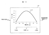
- FIG. 14 is an explanatory view showing a first configuration example of the end induction voltage regulator 133 constituting the voltage command value creators 103 and 103a shown in FIG.
- the end induction voltage regulator 133 receives the mover position xm, which is the output of the position detector 106, and outputs an end induction voltage adjustment gain.
- the mover position xm which is the output of the position detector 106
- the end induction voltage adjustment gain There are various conceivable ways of determining the end induction voltage adjustment gain. In any form, at the mover position xm where the change rate of the magnetic flux is small, the voltage component to be applied among the applied voltages is reduced according to the change of the magnetic flux.
- ) of the cosine function is output as the end induction voltage adjustment gain according to the input mover position xm.
- the flux linkage of the armature 9 with respect to the position of the mover (field element) 6 of the linear motor 104 has a characteristic such that the slope is zero at a position of ⁇ 0.01 m ( ⁇ 10 mm).
- the induced voltage constant Ke * becomes zero in the vicinity of -10 mm as the bottom dead center and in the vicinity of 10 mm as the top dead center.
- the unnecessary current flowing through the winding 8 can be suppressed, and the linear motor 104 can be driven with high efficiency. Further, since the loss in the power conversion circuit 105 can also be suppressed, a switching element and a radiation fin having a minimum necessary current capacity can be adopted, and the miniaturization of the linear motor drive device 101 can be realized.
- the voltage command value generator 103, 103a includes the end induction voltage regulator 133 so that a voltage corresponding to the induced voltage is always applied to the linear motor 104 regardless of the magnitude of the stroke or the positive / negative asymmetry of the stroke. Be done.
- a voltage having an absolute value of a voltage component corresponding to the rate of change of the magnetic flux generated due to the change in relative position between the armature 9 and the mover (field element) 6 is applied to the linear motor 104.
- the end induction voltage regulator 133 outputs a gain corresponding to the input mover position xm as an end induction voltage adjustment gain based on the characteristic curve indicating the relationship between the mover position and the gain stored in the storage unit. Do.
- FIG. 15 is an explanatory view showing a second configuration example of the end induction voltage regulator constituting the voltage command value creators 103 and 103a shown in FIG.
- the end induction voltage regulator 133a outputs, as an end induction voltage adjustment gain, a value obtained by differentiating the relationship of the armature interlinkage magnetic flux to the mover position shown in FIG. 3 at the mover position.
- the inclination (rate of change of the magnetic flux) of the armature differential flux is close to 1, so the end induction voltage regulator 133a outputs 1 as the end induction voltage adjustment gain Do.
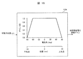
- FIG. 16 is an explanatory view showing a third configuration example of the end induction voltage regulator constituting the voltage command value creators 103 and 103a shown in FIG.
- the end induction voltage regulator 133b outputs 1 as an end induction voltage adjustment gain until a predetermined mover position (x1), and when the mover position exceeds x1, the absolute value of the mover position is obtained. It outputs an end induction voltage adjustment gain which decreases monotonically with respect to the increase.
- FIG. 16 shows an example in which the gain decreases in a linear function as an example of the monotonically decreasing gain.
- the armature differential magnetic flux with respect to the mover position xm may not be sinusoidal, and high-order components may be superimposed. In that case, it is sufficient to change the relationship between the mover position and the end induction voltage adjustment gain so that the end induction voltage adjustment gain does not decrease monotonically even after the predetermined mover position but has a maximum value. .
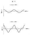
- FIG. 17 is an explanatory diagram of an applied voltage waveform
- the upper diagram of FIG. 17 shows a voltage waveform at the time of small stroke
- the lower diagram of FIG. 17 shows the voltage waveform at the large stroke.
- the linear motor drive device 101 outputs the waveform distorted in the area surrounded by the dotted line, that is, near the zero cross to the linear motor 104.
- the degree of distortion increases.
- FFT Fast Fourier Transform
- the distortion factor increases as the stroke increases.
- the distortion of the voltage waveform in the region (near the zero cross) surrounded by the dotted line is due to the inclusion of the harmonic component. That is, based on the characteristic curve showing the relationship between the mover position and the gain shown in FIG. 14 to FIG.
- the end The voltage waveform of the voltage command value V m2 * output from the voltage command value generator 103, 103a is multiplied by multiplying the end induced voltage adjustment gain output by the induced voltage regulator by the multiplier 92f (FIG. 13). It is a waveform in which the harmonics of the third order component are superimposed, that is, a waveform in which the harmonics of the third order component are included in the first order component. Therefore, the linear motor drive device 101 increases the content of the harmonic component near the zero crossing as the stroke increases, and outputs the applied voltage to the linear motor 104.
- FIG. 18 is an explanatory view showing a configuration example of a stroke controller 153 constituting the voltage command value creation unit 103a shown in the lower part of FIG.
- the stroke controller 153 obtains the difference between the stroke command value l * and the stroke detection value or stroke estimation value corresponding to the mover position xm by the subtractor 91a, and the difference is proportional thereto by the multiplier 92d.
- An operation result obtained by performing proportional control by multiplying the gain Kp_astr by the integral gain Ki_astr by the multiplier 92e, and integrating the result by integrating the result by the integrator 94d is added by the adder 90a, and the stroke command after adjustment is adjusted.
- Output the value l ** is a configuration of proportional integral control, other control configurations such as proportional control and integral control can also be applied.
- the mover 6 can be controlled according to the stroke command value, and even when the induced voltage constant Ke * can not be regarded as constant due to a change in stroke.
- a voltage corresponding to the induced voltage is applied to the linear motor 104. Thereby, high efficiency and miniaturization of the linear motor drive device 103a can be realized.
- the PWM signal generator 134 constituting the control unit 102 shown in FIG. 1 uses known pulse width modulation by comparing the carrier signal of the triangular wave and the voltage command value Vm *, and drives according to the voltage command value Vm * A signal is generated, and the generated drive signal is output to power conversion circuit 105.
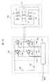
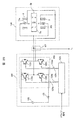
- FIG. 19 is a diagram showing a configuration example of the power conversion circuit 105 that constitutes the linear motor drive device 101 shown in FIG.
- the full bridge circuit 126 switches the DC voltage source 120 according to the drive signal input by the control unit 102, and outputs a voltage to the linear motor 104.
- the full bridge circuit 126 includes four switching elements 122, and includes first and second upper and lower arms (hereinafter referred to as U phase) having switching elements 122a and 122b connected in series, and second upper and lower arms having switching elements 122c and 122d.
- An arm hereinafter, referred to as a V phase
- U phase first and second upper and lower arms having switching elements 122a and 122b connected in series
- V phase An arm
- Switching element 122 performs switching operation according to pulse-like gate signals (124 a to 124 d) output from gate driver circuit 123 based on voltage command value Vm * generated by control unit 102 and a drive signal by pulse width modulation. it can. By controlling the conduction state (on / off) of switching element 122, a voltage corresponding to an AC voltage of DC voltage source 120 can be output to winding 8.
- a direct current source may be used instead of the direct current voltage source 120.
- the switching element 122 for example, a semiconductor switching element such as an IGBT or a MOS-FET can be employed.
- the linear motor 104 is connected between the switching elements 122 a and 122 b of the first upper and lower arms and between the switching elements 122 c and 122 d of the second upper and lower arms of the power conversion circuit 105.
- FIG. 19 shows an example in which the windings 8 of the upper and lower armatures 9 are connected in parallel, the windings 8 may be connected in series.
- a linear motor can be driven with high efficiency by suppressing the reactive current flowing in the winding without arranging a sensor for detecting the thrust of the linear motor in the linear motor. It becomes possible to provide a motor system. Specifically, at the mover position where the rate of change of the magnetic flux is small, a highly efficient linear motor system by reducing the voltage component (absolute value of the voltage component) of the applied voltage according to the change of the magnetic flux Can be realized. In addition, an efficient linear motor system is achieved by increasing the content ratio of the harmonic component of the voltage applied to the winding according to the increase in the relative position between the mover (field element) and the armature (stroke increase). Can be realized.
- the configuration of this embodiment can be the same as that of Embodiment 1 except for the following points.
- the present embodiment relates to a hermetic compressor 50 as an example of a device equipped with a linear motor system 200 described later.
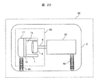
- FIG. 20 is a longitudinal sectional view of a hermetic compressor according to a second embodiment of the present invention, and is an example of a longitudinal sectional view of the hermetic compressor 50 having the linear motor 104.
- the hermetic compressor 50 is a reciprocating compressor in which the compression element 20 and the electric element 30 are disposed in the hermetic container 3.
- the compression element 20 and the motor element 30 are elastically supported in the closed container 3 by a support spring 49.
- the electric element 30 includes a mover (field element) 6 and an armature 9.
- the compression element 20 comprises a cylinder block 1 forming a cylinder 1 a, a cylinder head 16 assembled on the end face of the cylinder block 1, and a head cover 17 forming a discharge chamber space.
- the working fluid supplied into the cylinder 1a is compressed by the reciprocating motion of the piston 4, and the compressed working fluid is sent to a discharge pipe (not shown) communicating with the outside of the compressor.
- the working fluid for example, air or a refrigerant of a refrigeration cycle can be adopted.
- a piston 4 is attached to one end of the mover (field element) 6.
- the movable element (field element) 6 and the piston 4 reciprocate to compress and expand the working fluid.
- the work and the like required for the compression and expansion correspond to the fluctuating load.
- a compression element 20 is disposed at one end of the motorized element 30.
- the cylinder block 1 has a guide rod for guiding the reciprocating motion of the mover 6 along the longitudinal direction.
- a resonant spring 23 (not shown in FIG. 20) is added to the mover 6, and the mover (field device) 6 is operated at a mechanical resonance frequency determined by the mass of the mover (field device) 6 and the spring constant. When reciprocating, it is also necessary to consider the influence of the compression element 20 on the resonance frequency.
- the frequency at which the resonance state is obtained changes. That is, when the pressure of the cylinder 1a is high, it is equivalent to the spring constant of the resonance spring 23 added to the mover (field element) 6 being high, and the resonance frequency becomes high. On the other hand, when the pressure of the cylinder 1a is low, the spring constant of the resonance spring 23 added to the mover (field element) 6 becomes dominant, and the resonance frequency is the mass of the mover (field element) 6. It is close to the mechanical resonance frequency determined from the and spring constant.
- the resonance frequency changes depending on the conditions of the compression element 20 (suction pressure, discharge pressure, pressure difference between suction and discharge, etc.). Therefore, it is necessary to change the drive frequency in accordance with changes in load and resonance frequency.
- the voltage command value is created with the induced voltage constant Ke * fixed, excessive application voltage (applied voltage> induced voltage) is generated near the end of the stroke (positive maximum displacement and negative maximum displacement), which is wasteful.
- the efficiency of the linear motor 104 is lowered by the flow of the current.
- the influence that the resonance frequency changes can be taken from the phase relationship of the applied voltage Vm to the winding 8, the motor current Im, and the speed of the mover 6. Therefore, by controlling based on these phase relationships, a highly efficient linear motor system can be configured.
- the position estimator 135 estimates the position of the movable element 6 from the voltage Vm applied to the linear motor 104 and the motor current Im flowing through the linear motor 104, and estimates the position. Based on xm ⁇ , the resonant frequency is detected or estimated with high accuracy, and a highly efficient linear motor drive is provided.
- FIG. 21 is an overall schematic configuration diagram of a linear motor system 200 of the present embodiment.
- the linear motor system 200 has the same configuration as the linear motor system 100 in 1 in the above embodiment, but outputs the load current detector 150, the current detector 107, and the voltage command value Vm * .
- Voltage command value generator 103 b and position estimator 135 are different.
- the load current detector 150, the current detector 107, the voltage command value generator 103b, and the position estimator 135 will be described below.
- the other configuration is the same as that of the linear motor system 100 according to the first embodiment described above, and therefore the description thereof is omitted.
- FIG. 23 is an explanatory view showing a configuration example of a load current detector that constitutes the control unit 202 shown in FIG.
- the load current detector 150 of this embodiment extracts the amplitude of the load current component using a Fourier transform equation. Similar to the configuration of the phase difference detector 130 shown in FIG. 10, the load current detector 150 has a sine calculator 81 that outputs a sine of the input value and a cosine calculator 82 that outputs a cosine of the input value. , A reference phase ⁇ * which is a phase command value is input to obtain sine and cosine with respect to the reference phase ⁇ * .
- a value obtained by multiplying each of the sine and cosine by the motor current Im is output from the multiplier 92, respectively.
- the outputs are integrated by integrators 94e and 94f, respectively, to obtain first-order Fourier coefficients of sine and cosine respectively. That is, since the frequency components higher than the drive frequency ⁇ of the Fourier expansion can be eliminated, the configuration can be robust against high-order noise.
- the outputs of the integrators 94 e and 94 f are squared and input to the square root calculator 96. That is, the amplitude of the fundamental current is obtained by obtaining the root sum square root of the sine component and the cosine component, which are first-order Fourier coefficients of the sine and the cosine, respectively. Since the amplitude of the fundamental current also increases as the load increases, the configuration shown in FIG. 23 can detect the load current Im_ld.
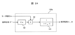
- FIG. 24 is an explanatory view showing another configuration example of the load current detector constituting the control unit 202 shown in FIG.
- the load current detector 150b inputs the reference phase ⁇ * , which is a phase command value, to the cosine calculator 82 that outputs the cosine of the input value, and obtains a cosine with respect to the reference phase ⁇ * .
- the cos component (Im_cos) of the fundamental frequency of the motor current Im is extracted.
- the cos component (Im_cos) of the fundamental frequency of the motor current Im is low-pass filtered (low-pass filter) processed by the first-order lag filter 141 and output as a load current Im_ld.
- FIG. 24 shows an example of the configuration of the first-order lag filter
- the low-pass filter may be configured with another known arrangement such as a second-order lag filter instead of the first-order lag filter.
- the configuration of FIG. 24 can detect the load current by filtering the extracted cosine component.
- the configuration of FIG. 24 is effective in reducing the calculation load.
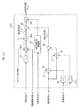
- FIG. 25 is an explanatory view showing a configuration example of the voltage command value creation unit 103b configuring the control unit 202 shown in FIG.
- voltage command value generator 103 b generates reference phase ⁇ * , position estimated value xm ⁇ which is an output of position estimator 135 described later, and load current Im_ld detected by load current detector 150.
- Voltage command value V m1 * corresponding to the induced voltage generated according to the speed of mover (field element) 6 and voltage command value V m3 * corresponding to the voltage drop due to the resistance and inductance of linear motor 104
- the voltage command value V m2 * obtained by vector addition is output.
- the multiplier 92 multiplies the load current Im_ld by the resistance value R m * and the inductance value L m * which are set or estimated in advance.
- the product of the load current Im_ld and the resistance value R m * is multiplied by the output of the cosine calculator 82 that outputs the cosine of the reference phase ⁇ * that is the input value by the multiplier 92, and the load current Im_ld and the inductance
- the value obtained by multiplying the value L m * is multiplied by the output of the sine calculator 81 a that outputs the negative sine of the reference phase ⁇ * that is the input value. Furthermore, these are added together by the adder 90 and output as a voltage command value V m3 * corresponding to the voltage drop.
- the voltage command value V m1 * and the voltage command value V m3 * both have an AC waveform, and thus are equivalent to outputting a vector sum (vector addition) in the voltage command value generator 103 b.
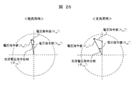
- FIG. 26 is a vector diagram showing the vector sum in the voltage command value creator 103b at light load and heavy load, and is an explanatory view showing vector addition in the voltage command value creator 103b as a vector diagram.
- the left diagram of FIG. 26 is a vector diagram at light load, that is, when the load current is small
- the right diagram of FIG. 26 is a vector diagram at heavy load, that is, when the load current is large.
- the voltage command value V m1 * corresponding to the induced voltage is the same vector.
- the counterclockwise direction is positive.
- the voltage command value V m3 * corresponding to the voltage drop due to the resistance and inductance of the linear motor 104 is vector-added to the voltage command value V m1 * corresponding to the induced voltage.
- the voltage command value V m @ 2 * amplitude increases Te the AC voltage command phase theta Vm * minute, the phase advances, the single-phase AC voltage command values V m @ 2 * is output. That is, even if the stroke of the movable element 6 is the same, in other words, the speed command value vm * is the same, the voltage command value V m2 * is appropriately controlled according to the load condition.
- the voltage V m2 * applied to the linear motor 104 can be adjusted by changing one of the stroke command value l * , the phase command value ⁇ * , and the speed command value vm * . Therefore, by adjusting the amplitude and frequency of the applied voltage, it is possible to control the drive frequency to the resonance frequency and to control the stroke.
- the voltage command value generator 103 b includes an end induction voltage regulator 133. Therefore, a voltage close to the induced voltage is applied to the linear motor 104 by multiplying the appropriate end induced voltage adjustment gain in accordance with the mover position, unnecessary current can be suppressed, and the linear motor 104 is driven with high efficiency. be able to.
- FIG. 27 is an explanatory view showing another configuration example of the voltage command value creation unit constituting the control unit 202 shown in FIG.
- voltage command value creation unit 103c generates a voltage after vector addition of voltage command value V m3 * corresponding to the voltage drop due to resistance and inductance with respect to voltage command value V m1 * corresponding to the induced voltage.
- a point different from the voltage command value creation device 103b shown in FIG. 25 is that the command value is multiplied by an end induction voltage gain which is an output of the end induction voltage regulator 133 by the multiplier 92f.
- the voltage command value generator 103 c is effective when the change in the inductance of the linear motor 104 is large at the end.
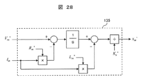
- ⁇ Position Estimator 135 The position estimation of the mover (field element) 6 is performed using, for example, the voltage Vm applied to the linear motor 104 and the current Im flowing through the linear motor 104 to obtain an estimated position value xm ⁇ according to the following equation (6).
- Vm * is a voltage command value Vm * applied to the linear motor 104.
- FIG. 28 is an explanatory view showing a configuration example of the position estimator 135 constituting the control unit 202 shown in FIG. 21, and an explanatory view in the case where Expression (6) is shown in a block diagram.
- position estimator 135 receives voltage command value Vm * and motor current Im, and multiplies the motor current Im by winding resistance value Rm * of linear motor 104 to obtain a voltage command value. Subtract from Vm * and obtain the result of calculating this reduced result by the integrator.
- a result obtained by multiplying the motor current Im by the winding inductance value Lm * of the linear motor 104 is obtained, and the result is subtracted from the result calculated by the above integrator, and this reduced result is divided by the induced voltage constant Ke * Outputs the position estimation value xm ⁇ .
- the position estimation method of the synchronous type motor known other than the above can be applied to the position estimator 135.
- a stroke can be calculated based on the position estimated value xm ⁇ and input to a stroke controller 153 shown in the lower part of FIG. 13 to control to a desired stroke.
- phase difference detector 130a In the first embodiment described above, the phase difference detector 130 shown in FIG. 10 is configured to receive the position xm of the mover (field element) 6 and the reference phase ⁇ * and calculate the phase difference dlt ⁇ .
- the present embodiment by using the motor current Im, it is possible to calculate the phase of the motor current Im with respect to the reference phase ⁇ * as shown in the following equation (7). This is because, as described above, when the resonance frequency changes from the assumed value, the influence can be seen from the phase relationship of the motor current Im.
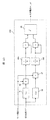
- FIG. 22 is an explanatory view showing a configuration example of the phase difference detector 130a constituting the control unit 202 shown in FIG. 21, and is an explanatory view in the case where Expression (7) is shown in a block diagram.
- a reference phase ⁇ * which is a phase command value, is input to each of a sine calculator 81 that outputs the sine of the input value and a cosine calculator 82 that outputs the cosine of the input value, with respect to the reference phase ⁇ * (phase command value).
- Get sine and cosine A value obtained by multiplying each of the sine and cosine by the motor current Im is output from the multiplier 92.
- the outputs are integrated by integrators 94a and 94b, respectively, to obtain first-order Fourier coefficients of sine and cosine respectively. That is, since the frequency components higher than the drive frequency ⁇ of the Fourier expansion can be eliminated, the configuration can be robust against high-order noise.
- the outputs of the integrators 94a and 94b are input to the inverse tangent unit 86.
- the arctangent device 86 outputs an arctangent value as a phase difference estimated value dlt ⁇ ⁇ based on the input sine and cosine components.
- the inverse tangent unit 86 of this embodiment outputs the inverse tangent value of the phase with the numerator as the output of the integrator 94a and the denominator as the output of the integrator 94b, but even if the numerator and the denominator are inverted, good.
- a highly efficient linear motor drive device 201 can be realized.
- FIG. 29 is a diagram showing a configuration example of a power conversion circuit 105 that constitutes the linear motor drive device 201 shown in FIG.
- the configuration of the power conversion circuit 105 and the connection with the linear motor 104 are the same as those of the first embodiment described above, and therefore the description thereof is omitted.
- the U-phase lower arm and the V-phase lower arm are provided with a current detector 107 such as a CT (current transformer).
- CT current transformer
- a shunt resistor 125 is added to the lower arm of the power conversion circuit 105, and a phase shunt current method is employed to detect the current flowing to the linear motor 104 from the current flowing to the shunt resistor 125 it can.
- a single shunt current detection method for detecting the current on the alternating current side of the power conversion circuit 105 from the direct current flowing in the shunt resistor 125 added to the direct current side of the power conversion circuit 105 may be adopted.
- the single shunt current detection method utilizes that the current flowing in the shunt resistor 125 temporally changes depending on the conduction state of the switching element 122 that constitutes the power conversion circuit 105.
- the voltage amplitude and the voltage phase are controlled according to the load, and the drive frequency is adjusted in consideration of the voltage phase.
- the linear motor can be driven at a mechanical resonance frequency including a load, and a highly efficient linear motor system can be configured, and at the mover position where the rate of change of the magnetic flux is small, Accordingly, a highly efficient linear motor system can be configured by reducing the voltage component (absolute value of the voltage component) to be applied.
- the control unit 102 constituting the linear motor drive device 101 in the above-mentioned first embodiment and the control unit 202 constituting the linear motor drive device 201 in the second embodiment are constituted by a semiconductor integrated circuit such as a microcomputer or DSP. It is often realized by Therefore, it is assumed that it becomes difficult to verify whether the linear motor drive devices 101 and 201 in the above-mentioned Example 1 and Example 2 are correctly configured. Therefore, the present embodiment relates to a verification system 600 that verifies whether the configuration of the linear motor drive devices 101 and 201 described above is operating correctly.
- FIG. 30 is an explanatory view showing a configuration example of a verification system of a third embodiment according to another embodiment of the present invention.
- a position detector 106 such as a laser displacement meter for detecting the position (stroke of the mover 6) of the mover (field element) 6 constituting the linear motor 104, or Is provided with a position estimator 135 (Example 2) which outputs an estimated value xm ⁇ of the position of the mover (field element) 6 based on the current detection value Im (motor current Im) which is the output of the current detector 107. It is done.
- verification system 600 includes at least control unit 102 for outputting a drive signal to power conversion circuit 105, power conversion circuit 105, linear motor 104, position detector 106, and verification device 190.
- the control unit 202 shown in the second embodiment may be replaced with the control unit 102, and the position estimation unit 135 shown in the second embodiment may be replaced with the position detector 106.
- a voltmeter 193 is inserted in the connection between the power conversion circuit 105 and the linear motor 104. Thereby, the line voltage applied to the linear motor 104 is measured. The voltmeter may detect the difference between the potential of each phase and the potential of the N (minus) side of the DC voltage source 120 as the voltage of each phase.
- a voltage is applied to the linear motor 104 by switching the DC voltage source 120 according to the drive signal input by the control unit 102.
- the voltage waveform detected by the voltmeter 193 is a pulse-shaped pulse-shaped waveform.
- the fundamental wave component is important in order to verify whether the linear motor drive devices 101 and 201 are correctly configured.
- the low pass filter 191 provided inside the verification device 190 outputs a drive frequency component from the voltage waveform detected by the voltmeter 193.
- the control unit 102 As a simple method of outputting the driving frequency component, for example, 1 ⁇ 5 to 1 of the triangular wave carrier signal (usually several kHz to several tens of kHz) of the PWM signal generator 134 constituting the control unit 102 A low pass filter (low pass filter, LPF) 191 having a cutoff frequency as low as about 10/10 is used.
- LPF low pass filter
- FFT conversion fast Fourier transform
- the configuration of this embodiment can be the same as that of Embodiment 1 or 2 except for the following points.
- the present embodiment relates to an air suspension system 300 as an example of a device equipped with a linear motor system.
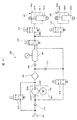
- 31 is a circuit diagram of an air suspension system 300 according to a third embodiment of the present invention
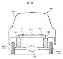
- FIG. 32 is a schematic view of a vehicle equipped with the air suspension system 300 shown in FIG.
- FIG. 32 only the distribution point 309N to be described later and the components on the air suspension 301, 302 side therefrom are illustrated.
- the air suspension system 300 includes two air suspensions 301 and 302, a compressor 303 driven by a linear motor 104, an intake filter 304, a first tank 305, an air dryer 307, and valves.
- the three check valves 308, 315, 317, the supply / discharge switching valve 310, the two suspension control valves 311, 312, the return passage on / off valve 314, and the exhaust passage on / off valve 319 are provided.
- the air suspension system 300 connects these by a passage through which air can flow.
- the air suspension system 300 is, for example, a system mounted on a vehicle 400 and controlling air pressure in air chambers 301C and 302C (FIG. 31) of the air suspensions 301 and 302, as shown in FIG.
- air suspensions 301 and 302 are provided between the wheel 410 side and the vehicle body 430 side, such as between the left wheel 410L and the right wheel 410R and the vehicle body 430, or between the hub and the vehicle body 430,
- the vehicle height can be adjusted by controlling the air pressure in the 302C.
- the air suspensions 301 and 302 may be attached between the axle 420 on the wheel 410 side and the vehicle body 430 of the vehicle 400 as shown in FIG. 32, and an arm of a suspension connecting the wheel 410 and the vehicle body 430. It may be attached between the class (wheel 410 side) and the vehicle body 430 or between the hub (wheel 410 side) of the wheel 410 and the vicinity of the vehicle body 430 mounting portion of the upper arm of the suspension (vehicle body 430 side). As described above, the air suspensions 301 and 302 may be provided to support the wheels 410 and the vehicle body 430. For example, the air suspensions 301 and 302 can be provided between the wheels 410 and the vehicle body 430 in the vertical direction. It is not restricted to the aspect attached to 430.
- an air suspension system 300 having two air suspensions will be described, but the number of air suspensions included in the air suspension system 300 is not particularly limited as long as it is one or more.
- the number of air suspensions can, for example, be equal to the number of wheels.
- a total of four air suspensions, two on the two front wheels and two on the two rear wheels, can be disposed.
- cylinders 301A and 302A for shock absorbing and the air chambers 301C and 302C serving as air springs are integrated, but the cylinder for shock absorbing as well known on the large vehicle and rear suspension side (Hydraulic shock absorber) 301A, 302A and an air spring may be provided independently.
- air chambers 301C and 302C are formed between the buffer cylinders 301A and 302A and the piston rods 301B and 302B, respectively, to form an air spring. ing.
- a passage described later is connected to each of the air chambers 301C and 302C, and the pressure and the vehicle height are controlled by the operation of the air suspension system 300.
- the compressor 303 can compress the air sucked from the suction port 303C and discharge the compressed air from the discharge port 303D.
- the compressor 303 includes a compressor body 303A and a linear motor 104.
- a pressure sensor is provided to measure the pressure of the suction port 303C or the discharge port 303D or both ports.
- a resonant spring 23 is added to the mover (field element) 6 of the linear motor 104, and the mover (field element) 6 is operated at a mechanical resonance frequency determined by the mass of the mover (field element) 6 and the spring constant.
- the resonance frequency is a mechanical resonance frequency determined from the mass of the mover 6 and the spring constant.
- the resonance frequency changes depending on the conditions of the compression element 20 (suction pressure, discharge pressure, pressure difference between suction and discharge, etc.). Therefore, it is necessary to change the drive frequency in accordance with changes in load and resonance frequency.
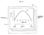
- FIG. 33 is an explanatory view showing a configuration example of the end induction voltage regulator 133 d constituting the voltage command value creation device.
- the end induction voltage regulator 133d is provided with a plurality of characteristic curves showing the relationship between the mover position and the gain, and the characteristic curves showing the relationship between the plurality of mover positions and the gain are previously associated with each pressure It stores in the memory
- the characteristic curve showing the relationship between the plurality of mover positions and the gain is a characteristic curve showing the relationship between the mover position and the gain in FIGS.
- the induced voltage regulator 133d is movable according to the pressure of the port among the characteristic curves indicating the relationship between the plurality of mover positions and gains stored in the storage unit (not shown) according to the pressure of the port.
- a characteristic curve indicating the relationship between the child position and the gain is selected, and an end induction voltage adjustment gain corresponding to the mover position xm is output.
- the characteristic curve showing the relationship between one mover position and gain is named from the name of the characteristic curve showing the relationship between a plurality of mover positions and gain. It is selected.
- the voltage component (absolute value of the voltage component) to be applied according to the change of the magnetic flux in the applied voltage is reduced to achieve high efficiency linear.
- the motor system can be configured.
- the compressor shown in the above-mentioned second embodiment can be applied to a compressor for pumping the refrigerant.
- the linear motor drive shown in the above-mentioned Embodiment 1 or 2 can be adopted as a linear motor drive which controls the drive of the compressor.
- the compressor shown in the above-mentioned second embodiment is also applicable to a compressor for pumping liquid refrigerant in a refrigerator having a condenser and an evaporator.
- the linear motor drive shown in the above-mentioned Embodiment 1 or 2 can be adopted as a linear motor drive which controls the drive of the compressor.
- the present invention is not limited to the embodiments described above, but includes various modifications.
- the embodiments described above are described in detail in order to explain the present invention in an easy-to-understand manner, and are not necessarily limited to those having all the configurations described.
- each of the configurations, functions, processing units, processing procedures, and the like described above may be realized by hardware, for example, by designing part or all of them with an integrated circuit.
- each configuration, function, and the like described above may be realized by software by a processor interpreting and executing a program that realizes each function.
- the power conversion circuit 105 may output a current.
- a current command value creator may be provided instead of the voltage command value creator.
Landscapes
- Engineering & Computer Science (AREA)
- Power Engineering (AREA)
- Physics & Mathematics (AREA)
- Chemical & Material Sciences (AREA)
- Combustion & Propulsion (AREA)
- Electromagnetism (AREA)
- Mechanical Engineering (AREA)
- General Engineering & Computer Science (AREA)
- Control Of Linear Motors (AREA)
- Compressors, Vaccum Pumps And Other Relevant Systems (AREA)
- Linear Motors (AREA)
Abstract
リニアモータの推力を検出するセンサをリニアモータ内に配することなく、巻線に流れる無効電流を抑制し、リニアモータを高効率に駆動し得るリニアモータシステム及びそれを有する圧縮機を提供する。リニアモータシステム100は、少なくとも、巻線8が捲回された磁性体を有する電機子9と、永久磁石を有する界磁子6と、電機子9又は界磁子6に接続された弾性体23とを有し、弾性体23の変形に応じて界磁子6と電機子9の相対位置が変動することで、軸方向に界磁子6と電機子9を相対的に往復運動させるリニアモータ104と、巻線に電圧を印加する制御部102と、を備える。制御部102は、巻線8に印加する電圧のうち、電機子9と界磁子6の相対位置の変動により生じる磁束の変化率に基づき、印加する電圧成分の絶対値を、磁束の変化率が小さい相対位置で小さくする。
Description
本発明は、リニアモータシステム及びそれを有する圧縮機に関する。
弾性体を接続させた可動子を、弾性体及び可動子の系における機械的な共振周波数で駆動させるリニアモータが知られている。
例えば、特許文献1には、リニア振動モータを制御するモータ駆動装置が開示され、モータ駆動装置は、モータドライバを有し、モータドライバは、推力定数を算出する演算処理が行われるよう上記リニア振動モータに直流電圧を印加する推力定数算出モード(非運転モード)と、リニア振動モータの通常運転が行われるよう上記リニア振動モータに交流電圧を印加する運転モードとを切り替える制御部を有する構成が記載されている。
そして特許文献1には、上記モータ駆動装置は、推力定数の算出に用いられる直流電圧印加時の推力検出値を求める推力検出部を備え、可動子の推力の検出は、可動子若しくは可動子が接する部位に取り付けられた圧力センサ或いは歪ゲージなどのセンサにより行われる旨開示されている。
しかしながら、特許文献1では、リニア振動モータの推力定数を算出するために必要となる推力の検出を、リニア振動モータ内に設けられる圧力センサ或いは歪ゲージなどのセンサにより行う構成であるため、配線が煩雑になるのみならず、装置の大型化を招きかねない。また、リニア振動モータの誘起電圧に応じた電圧を印加することで無効電流を抑制し、リニアモータを高効率に駆動する点については何ら考慮されていない。
そこで、本発明は、リニアモータの推力を検出するセンサをリニアモータ内に配することなく、巻線に流れる無効電流を抑制し、リニアモータを高効率に駆動し得るリニアモータシステム及びそれを有する圧縮機を提供する。
そこで、本発明は、リニアモータの推力を検出するセンサをリニアモータ内に配することなく、巻線に流れる無効電流を抑制し、リニアモータを高効率に駆動し得るリニアモータシステム及びそれを有する圧縮機を提供する。
上記課題を解決するため、本発明に係るリニアモータシステムは、少なくとも、巻線が捲回された磁性体を有する電機子と、永久磁石を有する界磁子と、前記電機子又は前記界磁子に接続された弾性体とを有し、前記弾性体の変形に応じて前記界磁子と前記電機子の相対位置が変動することで、軸方向に前記界磁子と電機子を相対的に往復運動させるリニアモータと、前記巻線に電圧を印加する制御部と、を備え、前記制御部は、前記巻線に印加する電圧のうち、前記電機子と前記界磁子の相対位置の変動により生じる磁束の変化率に基づき、印加する電圧成分の絶対値を、前記磁束の変化率が小さい相対位置で小さくすることを特徴とする。
また、本発明に係るリニアモータシステムは、少なくとも、巻線が捲回された磁性体を有する電機子と、永久磁石を有する界磁子と、前記電機子又は前記界磁子に接続された弾性体とを有し、前記弾性体の変形に応じて前記界磁子と前記電機子の相対位置が変動することで、軸方向に前記界磁子と電機子を相対的に往復運動させるリニアモータと、前記巻線に電圧を印加する制御部と、を備え、前記制御部は、前記界磁子と前記電機子の相対位置の増加に応じて、前記巻線に印加する電圧の高調波成分含有率を高くすることを特徴とする。
また、本発明に係る圧縮機は、少なくとも、巻線が捲回された磁性体を有する電機子と、永久磁石を有する界磁子と、前記電機子又は前記界磁子に接続された弾性体とを有し、前記弾性体の変形に応じて前記界磁子と前記電機子の相対位置が変動することで、軸方向に前記界磁子と電機子を相対的に往復運動させるリニアモータと、前記巻線に電圧を印加する制御部と、を備え、前記界磁子に接続されるピストンがシリンダ内を往復運動することにより作動流体を圧縮する圧縮機であって、前記制御部は、前記巻線に印加する電圧のうち、前記電機子と前記界磁子の相対位置の変動により生じる磁束の変化率に基づき、印加する電圧成分の絶対値を、前記磁束の変化率が小さい相対位置で小さくすることを特徴とする。
本発明によれば、リニアモータの推力を検出するセンサをリニアモータ内に配することなく、巻線に流れる無効電流を抑制し、リニアモータを高効率に駆動し得るリニアモータシステム及びそれを有する圧縮機を提供することが可能となる。
上記した以外の課題、構成及び効果は、以下の実施形態の説明により明らかにされる。
上記した以外の課題、構成及び効果は、以下の実施形態の説明により明らかにされる。
以下、添付の図面を参照しつつ本発明の実施例を詳細に説明する。同様の構成要素には同様の符号を付し、重複する説明を省略する。
本発明の各種の構成要素は、必ずしも個々に独立した存在である必要はなく、複数の構成要素が一個の部材として形成されていること、一つの構成要素が複数の部材で形成されていること、或る構成要素が他の構成要素の一部であること、或る構成要素の一部と他の構成要素の一部とが重複していること、等を許容する。
以下、図面を用いて本発明の実施例について説明する。
本発明の各種の構成要素は、必ずしも個々に独立した存在である必要はなく、複数の構成要素が一個の部材として形成されていること、一つの構成要素が複数の部材で形成されていること、或る構成要素が他の構成要素の一部であること、或る構成要素の一部と他の構成要素の一部とが重複していること、等を許容する。
以下、図面を用いて本発明の実施例について説明する。
本実施例では、説明の便宜のため、互いに直交する前後方向、左右方向、及び上下方向という語を用いるが、重力方向は必ずしも下方向に平行である必要はなく、前後方向、左右方向、上下方向又はそれ以外の方向に平行にすることができる。
<リニアモータ駆動装置101>
図1は、本発明の一実施例に係る実施例1のリニアモータシステム100の全体概略構成図である。リニアモータシステム100は、リニアモータ駆動装置101及びリニアモータ104とから構成される。後述するようにリニアモータ104は、相対移動する電機子9及び可動子6を有する。
リニアモータ駆動装置101は、位置検出器106、制御部102、及び電力変換回路105を有する。
位置検出器106は、電機子9に対する可動子6の相対位置(可動子位置)を検出する。本実施例では、可動子(界磁子)6が鉛直方向に移動するが、電機子9及び可動子(界磁子)6が相対移動すれば良く、電機子9が鉛直方向に移動する態様でも良い。また、電機子9及び可動子(界磁子)6が互いに異なる速度で鉛直方向(軸方向)に沿って往復運動する構成としても良い。何れの場合においても、鉛直方向(軸方向)に沿って移動する物体に共振バネ(アシストバネ)23の一端を接続することが好ましい。なお、以下では、可動子(界磁子)6が鉛直方向に往復運動する場合を一例として説明するが、往復運動の方向は鉛直方向に限られるものではない。例えば、可動子(界磁子)6が水平方向に往復運動するよう構成しても良く、また、鉛直方向に対し任意の角度を有する方向に可動子(界磁子)6が往復運動する構成としても良い。また、これらは、電機子9につても同様である。
制御部102は、位置検出器106の検出結果に応じて、電力変換回路105への出力電圧指令値、又は電力変換回路105を駆動するドライブ信号(パルス信号)を出力する。詳細は後述するが、電力変換回路105は、直流電圧源120(図19)の電圧を変換して交流電圧を出力する電力変換部の一例である。なお、直流電圧源120に代えて直流電流源を用いても良い。
<リニアモータ104>
図2はリニアモータ104の斜視図(電機子の構成例の斜視図)である。本実施例のリニアモータ104は、電機子9に対して、永久磁石2(2a,2b)が並んだ方向(前後方向)に相対移動可能な可動子6を有する。電機子9は空隙を介して上下方向に対向する2つの磁極7と、磁極7に捲回された巻線8とを有している。可動子6は、この空隙に配置されている。磁極7は、可動子6に対向する端面としての磁極歯70(ティースとも称される)を有している。
電機子9は、可動子6に対して前後方向の力(以下、推力と称する)を付与できる。例えば、後述するように、可動子6が前後方向に往復運動するように推力を制御できる。 可動子6は、上下方向に磁化した2つの平板状の永久磁石2(2a,2b)を有している。後側の永久磁石2a及び前側の永久磁石2bは、互いに反対方向に磁化されている。
本実施例では、後側の永久磁石2aは上側にN極を有し、前側の永久磁石2bは上側にS極を有している。図2では、永久磁石2a,2bは図示しているが、可動子6は図示していない。可動子6としては、例えば、平板状の永久磁石2を固定した平板状のものを採用できる。
制御部102は、可動子6を永久磁石2a,2bが電機子9に対向する範囲で往復運動させるようにドライブ信号を出力する。
図3は、可動子(界磁子)位置に対する電機子鎖交磁束の変化の例を示す図である。横軸を可動子(界磁子)位置(m)、縦軸を磁束(Wb)とし、磁束(Wb)は巻線に電流を流していない時の鎖交磁束であり、永久磁石2による磁束の変化を示している。
巻線8には磁束の時間微分に相当する電圧が誘起され、この電圧は一般的に、誘起電圧、逆起電圧、速度起電圧、などと称される。同じモータでも、可動子の速度に応じて変化し、例えば可動子の速度が高い場合に、誘起電圧が高くなる。
巻線8には磁束の時間微分に相当する電圧が誘起され、この電圧は一般的に、誘起電圧、逆起電圧、速度起電圧、などと称される。同じモータでも、可動子の速度に応じて変化し、例えば可動子の速度が高い場合に、誘起電圧が高くなる。
可動子(界磁子)位置に対する磁束の変化の傾き(磁束の変化率)を誘起電圧定数Keとすると、図3において示す(1)の区間においては、誘起電圧定数Keは一定とみなせる。この場合、誘起電圧定数Keに可動子の速度を乗算すると、誘起電圧を算出できる。
一方、図3において示す(2)の区間においては、磁束の変化の傾き(磁束の変化率)が一定ではないため、誘起電圧定数Keは可動子位置に依存する特性となる。つまり、図3のような特性のリニアモータにおいては、可動子(界磁子)位置が中心から離れて往復動する場合には、誘起電圧を算出するのが困難となるという課題がある。
可動子が機械的に拘束されていないフリーピストン構造の場合、可動子位置の最大あるいは最小位置は一定とは限らないため、可動子の瞬時速度が同じでも可動子の位置によって、誘起電圧が変わるという課題がある。なお、回転運動を直線運動に変換する機構を備えている場合には、このような課題は生じない。
リニアモータに流れる電流は、リニアモータに印加する電圧と誘起電圧の関係で定まる。そのため、誘起電圧を正しく算出できないと、印加電圧過多により無用に電流が増え、リニアモータの効率が低下するという問題が発生する。これは、リニアモータを駆動する回路の効率も低下するという問題が発生する。駆動回路の効率が低下すると、その分発熱量が増えるため、放熱フィンの面積を大きくする必要があり、システムが大型化してしまう。
リニアモータに流れる電流は、リニアモータに印加する電圧と誘起電圧の関係で定まる。そのため、誘起電圧を正しく算出できないと、印加電圧過多により無用に電流が増え、リニアモータの効率が低下するという問題が発生する。これは、リニアモータを駆動する回路の効率も低下するという問題が発生する。駆動回路の効率が低下すると、その分発熱量が増えるため、放熱フィンの面積を大きくする必要があり、システムが大型化してしまう。
図4は、図2のA-A’線に沿った平面での断面図である(A―A’断面矢視図)。図3に示すように、磁極7及びヨーク7eは、例えば鉄などの磁性体で一体的に形成され、磁気回路を構成している。図4の矢印線は、2つの巻線8に電流を流したときの磁束線の一例を示している。磁束の流れの向きは、巻線8に流れる電流の向きにより逆方向になり得るため、図に示す限りではない。この磁束線により、磁極歯70が磁化される。
[可動子6に付与する推力]
図5は磁極歯70の磁化により、可動子6が受ける推力を説明する図である。巻線8に流れる電流により生じる磁極歯70の極性を、図中の磁極歯70近傍に付した「N」、「S」で表している。また、図5において白抜き矢印は巻線8を流れる電流の向きを示している。図5の左図は、巻線8を流れる電流により、上側の磁極歯70aが「S」、下部の磁極歯70bが「N」に磁化されることにより、可動子6が前方向に力を受け、可動子6が前に移動した例を示している。図5の右図は、巻線8を流れる電流により、上部の磁極歯70aが「N」、下部の磁極歯70bが「S」に磁化されることにより、可動子6が後ろ方向に力を受け、可動子6が後ろに移動した例を示している。
図5は磁極歯70の磁化により、可動子6が受ける推力を説明する図である。巻線8に流れる電流により生じる磁極歯70の極性を、図中の磁極歯70近傍に付した「N」、「S」で表している。また、図5において白抜き矢印は巻線8を流れる電流の向きを示している。図5の左図は、巻線8を流れる電流により、上側の磁極歯70aが「S」、下部の磁極歯70bが「N」に磁化されることにより、可動子6が前方向に力を受け、可動子6が前に移動した例を示している。図5の右図は、巻線8を流れる電流により、上部の磁極歯70aが「N」、下部の磁極歯70bが「S」に磁化されることにより、可動子6が後ろ方向に力を受け、可動子6が後ろに移動した例を示している。
このように、巻線8に電圧や電流を印加することで、2つの磁極7を含む磁気回路に磁束を供給して、対向する2つの磁極歯70(磁極歯組)を磁化できる。電圧や電流として、例えば正弦波や矩形波(方形波)といった交流の電圧や電流を与えることで、可動子6を往復運動させる推力を与えることができる。これにより可動子6の運動を制御できる。
なお、可動子6に付与する推力は、印加する交流電流や交流電圧の振幅を変更することで変えられる。また、可動子6に付与する推力を既知の方法を用いて適切に変更することで、可動子6の変位を所望に変えられる。ここで、可動子6が往復運動(例えば、図5の左図及び右図のような磁極歯70の磁化を順次繰り返すことで可動子6に生じる運動)をする場合、交流波形的に変化する可動子6の変位の変化量をストロークと称する。
磁極歯70は磁性体であるため、永久磁石2を吸引する磁気吸引力が作用する。本実施例では可動子6を挟むよう間隙を介して2つの磁極歯70を対向配置しているため、可動子6に作用する磁気吸引力の合力を低減できる。
磁極歯70は磁性体であるため、永久磁石2を吸引する磁気吸引力が作用する。本実施例では可動子6を挟むよう間隙を介して2つの磁極歯70を対向配置しているため、可動子6に作用する磁気吸引力の合力を低減できる。
[可動子6外部の機構]
図6は、可動子6に接続される外部機構の説明図であり、例えば、コイルバネである共振バネ23(アシストバネ)によって構成される外部機構を可動子6の一端に接続し、そのバネ力により可動子6が戻される機構を説明する図である。共振バネ23は、一端が中間部24を介して可動子6に接続し、他端が基部25に固定されている。また、共振バネ23の延在方向と略平行に延在し、共振バネ23を案内又は支持する側部26が設けられている。リニアモータ104を往復運動させる場合、可動子6の運動方向が変わる度に、加速と減速を繰り返す。減速時は、可動子6の速度エネルギーが電気エネルギーに変換される(回生動作)が、リニアモータ104への配線の抵抗によって損失が生じる。一方、図6のように、可動子6に共振バネ23(アシストバネ)を付加し、可動子6の質量とバネ定数から決まる機械的な共振周波数で、可動子6を往復運動させる場合、可動子6の速度エネルギーを有効活用でき、高効率なリニアモータ駆動システムを構成することができる。共振バネ23に代えて、例えば、板バネ、或は、適度なヤング率を有しコイルバネを用いた場合と同様に伸縮するゴム等の弾性体を用いても良い。このように構成すると、可動子(界磁子)6が鉛直方向に移動する可動子(界磁子)移動型として構成されるが、可動子6に代えて電機子9に弾性体を接続して電機子9を鉛直方向に移動させる電機子移動型として構成しても良い。
図6は、可動子6に接続される外部機構の説明図であり、例えば、コイルバネである共振バネ23(アシストバネ)によって構成される外部機構を可動子6の一端に接続し、そのバネ力により可動子6が戻される機構を説明する図である。共振バネ23は、一端が中間部24を介して可動子6に接続し、他端が基部25に固定されている。また、共振バネ23の延在方向と略平行に延在し、共振バネ23を案内又は支持する側部26が設けられている。リニアモータ104を往復運動させる場合、可動子6の運動方向が変わる度に、加速と減速を繰り返す。減速時は、可動子6の速度エネルギーが電気エネルギーに変換される(回生動作)が、リニアモータ104への配線の抵抗によって損失が生じる。一方、図6のように、可動子6に共振バネ23(アシストバネ)を付加し、可動子6の質量とバネ定数から決まる機械的な共振周波数で、可動子6を往復運動させる場合、可動子6の速度エネルギーを有効活用でき、高効率なリニアモータ駆動システムを構成することができる。共振バネ23に代えて、例えば、板バネ、或は、適度なヤング率を有しコイルバネを用いた場合と同様に伸縮するゴム等の弾性体を用いても良い。このように構成すると、可動子(界磁子)6が鉛直方向に移動する可動子(界磁子)移動型として構成されるが、可動子6に代えて電機子9に弾性体を接続して電機子9を鉛直方向に移動させる電機子移動型として構成しても良い。
図7は、駆動周波数とストロークの関係の説明図であり、交流電圧の駆動周波数を横軸に、可動子6のストロークを縦軸にとり、これらの関係を示す図である。各駆動周波数における交流電圧の振幅は同一である。図7から分かるように、共振周波数付近で可動子6のストロークが急峻に大きくなり、共振周波数から離れるとストロークが小さくなる特性を示す。共振周波数は、共振バネ23のバネ定数kを可動子6の質量mで除した値の平方根で与えられるが、リニアモータ104の系によっては、この値は近似値となる。
このように、共振周波数又はこの近傍の駆動周波数の交流電圧を印加することで、大きなストローク(大きなエネルギー)で振動させることができる。つまり、可動子6に共振バネ23等の弾性体を付加したリニアモータ104を制御する場合には、可動子6の共振周波数を検出あるいは推定することが重要である。可動子6のストロークを所望に制御する場合においても可動子6の共振周波数を検出あるいは推定することが重要である。
このように、共振周波数又はこの近傍の駆動周波数の交流電圧を印加することで、大きなストローク(大きなエネルギー)で振動させることができる。つまり、可動子6に共振バネ23等の弾性体を付加したリニアモータ104を制御する場合には、可動子6の共振周波数を検出あるいは推定することが重要である。可動子6のストロークを所望に制御する場合においても可動子6の共振周波数を検出あるいは推定することが重要である。
[駆動時の位相関係]
図8は、可動子の位置と可動子の速度との位相関係、及び印加電圧とモータ電流の位相関係の説明図である。リニアモータ104を駆動した際の、図8の上図に可動子6の位置と速度の時間変化、図8の下図に印加電圧波形とリニアモータ104に流れる電流の時間変化の関係を示している。なお、図8の上図と下図は、同じタイミングの波形である。図9は、図8の交流波形をベクトルとして示した図である。共振バネ23を有する外部機構を接続した可動子6を往復運動させると、可動子6の変位は正弦波状に変化する。可動子6の速度は変位の時間微分であるため、余弦波状に変化する。そのため、これらは直交2軸上にベクトルとして示すことができる。図8および図9より、可動子6の速度、印加電圧、およびモータ電流はほぼ同位相であることがわかる。
また、可動子6に共振バネ23を付加し、可動子6の質量とバネ定数から定まる機械的な共振周波数で可動子6を往復運動させる場合、可動子6の位置の位相は、巻線8への印加電圧Vm、モータ電流Im、及び可動子6の速度の位相それぞれに対して90度の位相差となることが知られている。すなわち、これらの何れかの関係が成立している時は、共振周波数で駆動していると推定できる。
リニアモータ104の巻線抵抗や巻線インダクタンスの値、あるいは可動子6に付加された負荷要素によっては、巻線8への印加電圧Vm、モータ電流Im、及び可動子6の速度の位相関係は必ずしも90度の位相差とは限らないため、条件によって変更する制御部を備えることが望ましい。この時、特に、負荷の変動に起因するモータ電流Imの変化を考慮するのが望ましい。
製造バラつきによって可動子6の質量が想定からずれている場合や、可動子6に付加された負荷要素によって、共振バネ23に接続される質量が変化する場合は、共振周波数が変化してしまう。また、可動子6に付加された負荷要素が位置依存性を有する場合においては、駆動中に共振周波数が変化してしまう。このような場合においても所望のストロークを得るためには、条件によって変化する共振周波数を高精度に検出あるいは推定することが好ましい。
<制御部102>
図1に示すように、制御部102は、位相差検出器130、位相差検出器130の出力である位相差dltθが位相差指令値に追従するように駆動周波数指令値ω*を調整する駆動周波数調整器131、積分器140、電圧指令値Vm*を出力する電圧指令値作成器103、及び、電圧指令値Vm*と三角波キャリア信号を比較して、電圧を出力する電力変換回路105を駆動するドライブ信号を出力するPWM信号作成器134から構成される。
制御部102は、位置検出器106による可動子(界磁子)位置検出値xmを入力する。ここで、位置検出器106として、例えば、レーザ変位計などが用いられる。制御部102に入力された可動子(界磁子)位置検出値xmは、制御部102を構成する位相差検出器130に入力される。位相差検出器130は、詳細後述する位相指令値である基準位相θ*と可動子(界磁子)位置検出値xmの位相差dltθを出力する。位相差検出器130より出力される位相差dltθは駆動周波数調整器131に入力される。駆動周波数調整器131は、入力された位相差dltθに基づき周波数指令値ω*を出力する。周波数指令値ω*に基づく印加電圧Vmが、リニアモータ104へ出力される。
可動子(界磁子)6が往復動している場合、可動子(界磁子)位置xmは交流波形であり、最大変位と最小変位の差がストロークである。なお、フリーピストン構造の場合は、最大変位と最小変位の絶対値が異なる場合もあり、この場合、弾性体の弾性力が釣り合う中心を基準(ゼロ)とし、正の最大変位を正側ストローク、負の最大変位の絶対値を負側ストロークと称する。すなわち、正側ストロークと負側ストロークの加算が、ストロークである。駆動条件によっては正側ストロークと負側ストロークは異なる場合もある。
可動子6の質量や共振バネ23のバネ定数が想定からずれている場合、共振周波数が想定値から変化してしまうが、その影響は巻線8への印加電圧Vm、モータ電流Im、及び可動子6の速度の位相関係から見て取れるため、これらの位相関係を基に制御することで、高効率なリニアモータシステムを構成することができる。可動子6に付加された負荷要素が位置依存性を有する場合においても、巻線8への印加電圧Vm、モータ電流Im、及び可動子6の速度の位相関係を基に制御することで、高効率なリニアモータシステムを構成することができる。
以下、制御部102を構成する上述の各部の構成或いは動作について説明する。
以下、制御部102を構成する上述の各部の構成或いは動作について説明する。
<基準位相作成器>
本実施例の位相指令値である基準位相θ*は、図1に示す駆動周波数調整器131の出力である駆動周波数指令値ω*を基準位相作成器としての積分器140で積分することで得る。すなわち、基準位相θ*は、印加電圧Vm(θ*)の目標周波数に相当する駆動周波数指令値ω*を持つ波動の各時刻の位相θ*である。このように、本実施例では基準位相θ*として駆動周波数調整器131の駆動周波数指令値ω*を用いているが、例えば可動子6を含む振動体の機械共振周波数に固定しても良い。
基準位相θ*は、駆動周波数指令値ω*が一定の間は、例えば、各時刻に対して[-π,π]、[0,2π]、又はこれより広い範囲を値域とする、のこぎり波としたり、時刻に対して線形に増加するようにしても良い。後述するように駆動周波数指令値ω*が変動した場合は、これに応じてのこぎり波や線形な増加の形状が変動する(傾きが変化する)。
<位相差検出器130>
可動子6が往復運動している場合、可動子6の位置xm及び速度、モータ電流Imは周期関数となる。周期関数はフーリエ級数で表せるため、フーリエ変換式を用いて可動子6の位置xmを表すと、次式(1)のように定義できる。
可動子6が往復運動している場合、可動子6の位置xm及び速度、モータ電流Imは周期関数となる。周期関数はフーリエ級数で表せるため、フーリエ変換式を用いて可動子6の位置xmを表すと、次式(1)のように定義できる。

ここで、x0は直流オフセット値、anおよびbnはn次のフーリエ係数であり、次式(2)及び式(3)で求められる。
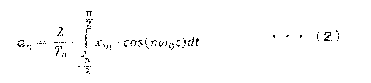

ここで、T0は基本波の周期(可動子6の往復運動する周期)、つまり1次周波数(駆動周波数)の逆数である。可動子6に共振バネ23が付加された、いわゆるバネマス系においては、可動子6の質量とバネ定数から決まる機械的な共振周波数が支配的な成分となる。そのため、基本波に注目すれば良い。
可動子6を共振周波数で駆動させようと制御する場合、高次成分は重要ではなく、1次成分、つまり駆動周波数成分に注目すれば良い。特に、可動子6の位置xmの1次周波数成分(駆動周波数成分)の位相が重要である。1次のフーリエ係数の逆正接により、正弦波状の印加電圧Vmに対する可動子6の位置xmを次式(4)で求めることができる。

式(4)では、積分範囲は、-2π~0となっている。これは、位相差検出器130をマイコンやDSP(Digital Signal Processor)等の半導体集積回路等で実現する場合に、過去の情報しか取得できないためである。
図10は、図1に示す制御部102を構成する位相差検出器130の構成例を示す説明図であって、式(4)をブロック図で示した場合の説明図である。入力値の正弦を出力する正弦演算器81及び入力値の余弦を出力する余弦演算器82のそれぞれに、位相指令値である基準位相θ*を入力し、基準位相θ*(位相指令値)に対する正弦及び余弦を得る。正弦及び余弦それぞれを可動子位置xmと乗算した値が乗算器92から出力される。その出力をそれぞれ積分器94a,94bで積分すると、正弦及び余弦それぞれの1次のフーリエ係数を得る。すなわち、フーリエ展開の駆動周波数ωより高次の周波数成分を消去できるので、高次のノイズに対してロバストに構成できる。
積分器94a,94bの出力を逆正接器86に入力する。逆正接器86は、入力された正弦及び余弦成分を基に逆正接値を出力する。本実施例の逆正接器86は、分子を積分器94aの出力、分母を積分器94bの出力とした位相の逆正接値を出力するが、分子と分母を逆にした値を出力しても良い。
積分器94a,94bの出力を逆正接器86に入力する。逆正接器86は、入力された正弦及び余弦成分を基に逆正接値を出力する。本実施例の逆正接器86は、分子を積分器94aの出力、分母を積分器94bの出力とした位相の逆正接値を出力するが、分子と分母を逆にした値を出力しても良い。
図11は、駆動周波数と位相差検出器130からの出力の関係の説明図である。すなわち、交流電圧の駆動周波数(横軸)と、逆正接器86の出力値(位相差dltθ(θpos^))(縦軸)の関係を示す図である。図11から分かるように、本実施例では、駆動周波数が共振周波数である場合、0°が逆正接器86から出力される。逆正接器86から出力される値は、駆動周波数が共振周波数より高い場合は0°より大きく、駆動周波数が共振周波数より低い場合は、0°より小さい。これにより、基準位相θ*に対する位相差検出器130への入力交流信号(本実施例では、可動子6の位置xm)の1次周波数成分の基準位相θ*に対する位相差dltθを求めることができ、共振周波数の推定が可能になる。そして例えば、位相差dltθが0°超の場合は、位相差dltθが低下するように制御し、0°未満の場合は、増加するように制御すれば良い。基準位相θ*と基本周波数ωとが同値となるときの位相差dltθを目標値dltθ*として制御することが好ましい。
なお、積分器94a、94bに代えて、不完全積分器を用いることができる。不完全積分器はローパスフィルタ(低域通過フィルタ)の一種で、1次遅れフィルタと同様の構成にできる。もちろん、1次遅れフィルタに限らず、2次遅れフィルタ等、他の既知の構成でローパスフィルタを構成しても良い。その他、不完全積分器に代えて、又は追加して、積分器94a,94b(又は不完全積分器)より前段に、ハイパスフィルタ(図示せず)を設けることができる。ハイパスフィルタの遮断周波数としては、例えば10Hz又は5Hz以下にすることができる。
このように、位相差検出器130は、駆動周波数成分の1次のフーリエ係数の比の逆正接を用い、交流電圧指令値V*に対する可動子6の位置xmの位相θを求めるとき、位相差検出器130への入力交流信号である可動子6の位置xmの1次周波数成分のみに大きな感度を有する。つまり、例えば、可動子6の位置xmに、直流オフセットや高次のノイズが重畳された場合においても、基準位相θ*に対する位相差検出器130への入力交流信号である可動子6の位置xmの1次周波数成分の位相dltθをより正確に求められる。また、ハイパスフィルタを上記のように設ける場合は、さらに駆動周波数ωより小さな周波数に対してもロバストに構成できる。
したがって、可動子6の位置xmの検出方法として、ノイズが重畳され易いシステム、例えばインダクタンスの可動子位置依存性が大きいシステムや、近傍に別の機器が存在するシステムを採用する場合に、特に有効な制御を実現できる。このように、高精度に共振周波数を検出あるいは推定し、高効率なリニアモータ駆動を実現することができる。
したがって、可動子6の位置xmの検出方法として、ノイズが重畳され易いシステム、例えばインダクタンスの可動子位置依存性が大きいシステムや、近傍に別の機器が存在するシステムを採用する場合に、特に有効な制御を実現できる。このように、高精度に共振周波数を検出あるいは推定し、高効率なリニアモータ駆動を実現することができる。
<駆動周波数調整器131>
図12は、図1に示す制御部102を構成する駆動周波数調整器131の構成例を示す説明図である。駆動周波数調整器131は、位相差指令値dltθ*(例えば、0°)と位相差検出器130で求めた位相差dltθの差を減算器91で求め、これに乗算器92bで比例ゲインKp_adtrを乗じて比例制御した演算結果と、乗算器92cで積分ゲインKi_adtrを乗じ、その結果を積分器94cで積分する積分制御した演算結果とを加算器90で加算し、当該加算結果に更に周波数指令初期値(ω0)を加算することで駆動周波数指令値ω*を出力する。
なお、周波数指令初期値(ω0)は、上位の制御器(図示せず)から得ても良いし、予め例えば0°と設定しても良い。また、本実施例の駆動周波数調整器131は、比例積分制御の構成であるが、比例制御や積分制御など、他の制御構成も適用できる。
[高効率駆動の実現]
リニアモータ104を可動子6の質量とバネ定数から定まる機械的な共振周波数で駆動する場合の位相差検出器130と駆動周波数調整器131の動作を説明する。
例えば、可動子6の質量が設計値よりも重かった場合、実際の共振周波数は、設計値よりも低くなる。つまり、可動子6の質量設計値を用いて駆動周波数の初期値を決めた場合(設計値を利用して駆動周波数指令値ω*の初期値を決めた場合)には、実際の共振周波数よりも高い周波数で駆動することになる。この時、位相差検出器130で求めた位相差dltθは、位相差指令値dltθ*よりも大きい値となる。そのため、駆動周波数調整器131は、駆動周波数指令値ω*を減少させる制御を実行し、その結果、駆動周波数指令値ω*が実際の共振周波数に一致する。したがって、可動子6の速度エネルギーを有効活用でき、高効率にリニアモータ104を駆動することができる。
<電圧指令値作成器>
図13は、図1に示す制御部102を構成する電圧指令値作成器103の構成例を示す説明図である。電圧指令値作成器103は、可動子6の速度に応じて生じる誘起電圧に相当する電圧指令値Vm2 *を生成する。
図13の上図は、ストローク制御器を有しない、いわゆるオープン指令型の構成例である。電圧指令値作成器103は、余弦演算器82b、乗算器92d~92f、及び端部誘起電圧調整器133を備える。
電圧指令値作成器103は、予め設定された、或は、上位の制御器(図示せず)などから得るストローク指令値l*と、駆動周波数調整器131の出力である駆動周波数指令値ω*と、基準位相作成器としての積分器140の出力である基準位相θ*と、位置検出器106の出力である可動子位置xmと、を入力する。
入力値の余弦を出力する余弦演算器82bに基準位相θ*を入力し、その余弦出力と、ストローク指令値l*と、駆動周波数指令値ω*と、を乗算器92dにて乗算し、速度指令値vm*を得る。速度指令値vm*は、可動子6の位置の指令値xm*の微分から求めることもでき、図13の構成の基となる演算式を次式(5)に示す。

速度指令値vm*は、ストローク指令値l*を振幅とした正弦波で表すことができる。
正弦波を時間微分すると余弦波になるため、図13の上図に示す構成とすると微分演算を省略することができ、制御部102への実装が容易になる。
正弦波を時間微分すると余弦波になるため、図13の上図に示す構成とすると微分演算を省略することができ、制御部102への実装が容易になる。
速度指令値vm*に、誘起電圧定数Ke*を乗算器92eにて乗じ、誘起電圧定数Ke*が一定とした場合の誘起電圧に相当する電圧指令値Vm1
*を生成する。
ここで、駆動するリニアモータ104の特性として、可動子位置に対する電機子9の鎖交磁束の変化が図3に示した様な特性の場合、ストロークが大きい場合には誘起電圧定数Ke*を一定とは見做すことができない。
仮に、誘起電圧定数Ke*を一定として電圧指令値Vm1 *を作成した場合、ストロークの端部(正の最大変位および負の最大変位)近傍で印加電圧過多(印加電圧>誘起電圧)となり、無駄な電流が流れることで、リニアモータの効率が低下する。
また、リニアモータの効率のみならず、後述する電力変換回路105での損失も増える。さらに、大電流に対応するために、電流容量の大きな(一般的に面積の大きい)スイッチング素子を使う必要がある。その結果、電力変換回路自体や放熱フィンが大きくなってしまい、リニアモータ駆動装置101の小型化が困難となる。
そこで、本実施例では、誘起電圧定数Ke*が一定とした場合の誘起電圧に相当する電圧指令値Vm1 *に、乗算器92fにて端部誘起電圧調整器133の出力である端部誘起電圧調整ゲインを乗ずることで、リニアモータ104に印加する電圧指令値Vm2 *を生成する。詳細後述する端部誘起電圧調整器133は、位置検出器106より可動子位置xmを入力し、可動子位置xmに対応する端部誘起電圧調整ゲインを出力するものである。
図13の下図は、ストローク制御器153を有する、いわゆるクローズ指令型の電圧指令値作成器103bの構成例である。電圧指令値作成器103bは、余弦演算器82b、乗算器92d~92f、端部誘起電圧調整器133、及びストローク制御器153を備える。
電圧指令値作成器103bは、予め設定された、或は、上位の制御器(図示せず)などから得るストローク指令値l*と、駆動周波数調整器131の出力である駆動周波数指令値ω*と、基準位相作成器としての積分器140の出力である基準位相θ*と、位置検出器106の出力である可動子位置xmと、を入力する。
電圧指令値作成器103bは、予め設定された、或は、上位の制御器(図示せず)などから得るストローク指令値l*と、駆動周波数調整器131の出力である駆動周波数指令値ω*と、基準位相作成器としての積分器140の出力である基準位相θ*と、位置検出器106の出力である可動子位置xmと、を入力する。
入力値の余弦を出力する余弦演算器82bに基準位相θ*を入力し、その余弦出力と、入力されるストローク指令値l*及び可動子位置xmに基づきストローク制御器153より出力されるストローク指令値l**と、駆動周波数指令値ω*と、を乗算器92dにて乗算し、速度指令値vm*を得る。
速度指令値vm*に、誘起電圧定数Ke*を乗算器92eにて乗じ、誘起電圧定数Ke*が一定とした場合の誘起電圧に相当する電圧指令値Vm1 *を生成する。誘起電圧定数Ke*が一定とした場合の誘起電圧に相当する電圧指令値Vm1 *に、乗算器92fにて端部誘起電圧調整器133の出力である端部誘起電圧調整ゲインを乗ずることで、リニアモータ104に印加する電圧指令値Vm2 *を生成する。
すなわち、電圧指令値作成器103bは、位置検出器106の出力である可動子位置xmの相当するストローク検出値またはストローク推定値をフィードバックし、ストローク制御器153でストローク指令値を制御する。
速度指令値vm*に、誘起電圧定数Ke*を乗算器92eにて乗じ、誘起電圧定数Ke*が一定とした場合の誘起電圧に相当する電圧指令値Vm1 *を生成する。誘起電圧定数Ke*が一定とした場合の誘起電圧に相当する電圧指令値Vm1 *に、乗算器92fにて端部誘起電圧調整器133の出力である端部誘起電圧調整ゲインを乗ずることで、リニアモータ104に印加する電圧指令値Vm2 *を生成する。
すなわち、電圧指令値作成器103bは、位置検出器106の出力である可動子位置xmの相当するストローク検出値またはストローク推定値をフィードバックし、ストローク制御器153でストローク指令値を制御する。
<端部誘起電圧調整器>
図14は、図13に示す電圧指令値作成器103,103aを構成する端部誘起電圧調整器133の第1の構成例を示す説明図である。端部誘起電圧調整器133は、位置検出器106の出力である可動子位置xmを入力とし、端部誘起電圧調整ゲインを出力する。
端部誘起電圧調整ゲインの決め方は、様々な形態が考えられる。いずれの形態においても、磁束の変化率が小さい可動子位置xmにおいて、印加電圧のうち、磁束の変化に応じて印加する電圧成分を小さくする。
図14は、図13に示す電圧指令値作成器103,103aを構成する端部誘起電圧調整器133の第1の構成例を示す説明図である。端部誘起電圧調整器133は、位置検出器106の出力である可動子位置xmを入力とし、端部誘起電圧調整ゲインを出力する。
端部誘起電圧調整ゲインの決め方は、様々な形態が考えられる。いずれの形態においても、磁束の変化率が小さい可動子位置xmにおいて、印加電圧のうち、磁束の変化に応じて印加する電圧成分を小さくする。
まず図14に示す例では、入力される可動子位置xmに応じて、余弦関数の絶対値(|cosθ|)を端部誘起電圧調整ゲインとして出力する。図3に示したように、リニアモータ104の可動子(界磁子)6の位置に対する電機子9の鎖交磁束は、±0.01m(±10mm)の位置で傾きがゼロとなる特性を有する。換言すれば、図14において、下死点である-10mm近傍及び上死点である10mm近傍では、誘起電圧定数Ke*はゼロとなる。これは、上死点及び下死点近傍では可動子6の速度が略ゼロとなるため、可動子6に対する電機子9の鎖交磁束の傾き(磁束の変化率)がゼロとなるため誘起電圧が略ゼロとなることに因る。
そのため、端部誘起電圧調整ゲインを略ゼロとすることで、誘起電圧定数Ke*が一定として誘起電圧に相当する電圧指令値Vm1 *を生成する場合においても、電圧指令値作成器103,103aから出力される電圧指令値Vm2 *は、略ゼロとなる。これにより、リニアモータ104に印加される電圧は、リニアモータ104の誘起電圧の変化に応じて調整され、印加電圧が過多となることを防止できる。
従って、巻線8を流れる無駄な電流を抑制でき、リニアモータ104を高効率で駆動することができる。また、電力変換回路105での損失も抑制できることから、必要最小限の電流容量のスイッチング素子や放熱フィンを採用でき、リニアモータ駆動装置101の小型化を実現することができる。
一方、可動子6が中心位置付近で往復動している場合、端部誘起電圧調整ゲインは1に近い値となるため、誘起電圧定数が一定として誘起電圧に相当する電圧指令値Vm1
*(=Vm2
*)がリニアモータ104に印加される。すなわち、誘起電圧に近い電圧がリニアモータ104に印加され、無駄な電流を抑制できる。
このように、電圧指令値作成器103,103aが端部誘起電圧調整器133を備えることにより、ストロークの大小或いはストロークの正負非対称に拘わらず、常に誘起電圧に応じた電圧がリニアモータ104に印加される。換言すれば、電機子9と可動子(界磁子)6の相対位置の変動により生じる磁束の変化率に応じた電圧成分の絶対値を有する電圧がリニアモータ104に印加される。これにより、リニアモータ駆動装置101の高効率化と小型化を実現することが可能となる。
なお、図14に示す可動子位置とゲインとの関係を示す特性曲線は、端部誘起電圧調整器133内の予め図示しない記憶部に格納されている。端部誘起電圧調整器133は、記憶部に格納される可動子位置とゲインとの関係を示す特性曲線に基づき、入力される可動子位置xmに対応するゲインを端部誘起電圧調整ゲインとして出力する。
なお、図14に示す可動子位置とゲインとの関係を示す特性曲線は、端部誘起電圧調整器133内の予め図示しない記憶部に格納されている。端部誘起電圧調整器133は、記憶部に格納される可動子位置とゲインとの関係を示す特性曲線に基づき、入力される可動子位置xmに対応するゲインを端部誘起電圧調整ゲインとして出力する。
図15は、図13に示す電圧指令値作成器103,103aを構成する端部誘起電圧調整器の第2の構成例を示す説明図である。端部誘起電圧調整器133aは、図3に示した可動子位置に対する電機子鎖交磁束の関係を、可動子位置で微分した値を端部誘起電圧調整ゲインとして出力する。
可動子6が中心付近に位置する場合は、電機子差交磁束の傾き(磁束の変化率)は1に近くなるため、端部誘起電圧調整器133aは端部誘起電圧調整ゲインとして1を出力する。ストロークが少し大きくなると(例えば、8mm)、電機子差交磁束の傾き(磁束の変化率)が小さくなるため、それに応じて端部誘起電圧調整ゲインを1より小さい値にする。さらにストロークが大きくなり、可動子6が端部(上死点または下死点)まで往復動する場合においては、可動子位置が±10mm近傍においては、端部誘起電圧調整ゲインとしてゼロに近い値を出力する。
可動子6が中心付近に位置する場合は、電機子差交磁束の傾き(磁束の変化率)は1に近くなるため、端部誘起電圧調整器133aは端部誘起電圧調整ゲインとして1を出力する。ストロークが少し大きくなると(例えば、8mm)、電機子差交磁束の傾き(磁束の変化率)が小さくなるため、それに応じて端部誘起電圧調整ゲインを1より小さい値にする。さらにストロークが大きくなり、可動子6が端部(上死点または下死点)まで往復動する場合においては、可動子位置が±10mm近傍においては、端部誘起電圧調整ゲインとしてゼロに近い値を出力する。
図16は、図13に示す電圧指令値作成器103,103aを構成する端部誘起電圧調整器の第3の構成例を示す説明図である。端部誘起電圧調整器133bは、所定の可動子位置(x1)までは、端部誘起電圧調整ゲインとして1を出力し、可動子位置がx1を超えた場合は、可動子位置の絶対値の増加に対して単調減少となる端部誘起電圧調整ゲインを出力する。図16では、単調減少ゲインの例として、1次関数的にゲインが小さくなる例を示している。
なお、電機子9の構成によっては、可動子位置xmに対する電機子差交磁束が正弦波状ではなく、高次の成分が重畳されている場合もある。その場合は、端部誘起電圧調整ゲインは、所定の可動子位置を越えても単調減少ではなく、極大値を持つように、可動子位置と端部誘起電圧調整ゲインの関係を変更すれば良い。
このように、いくつか構成例を示した端部誘起電圧調整器であるが、リニアモータ104に印加される電圧波形で見ると、図17に示す電圧波形となる。図17は印加電圧波形の説明図であり、図17の上図は小スクローク時の電圧波形を示し、図17の下図は大スクローク時の電圧波形を示している。図17の上図に示すように、ストロークが小さい時は余弦波に近い波形をリニアモータ駆動装置101がリニアモータ104へ出力する。一方、図17の下図に示すように、ストロークが大きい時は、点線で囲まれる領域、すなわち、ゼロクロス近傍で歪んだ波形を、リニアモータ駆動装置101がリニアモータ104へ出力する。ストロークが増加するに従い、歪具合が大きくなる。換言すれば、印加電圧の波形をFFT(Fast Fourier Transform)などで周波数分析すると、ストロークが大きくなるに従い、歪率が大きくなる。
なお、図17の下図において、点線で囲まれる領域(ゼロクロス近傍)における電圧波形の歪は、高調波成分の含有に因るものである。すなわち、上述の図14~図16に示した可動子位置とゲインとの関係を示す特性曲線に基づき、可動子6が端部(上死点または下死点)近傍に位置するとき、端部誘起電圧調整器が出力する端部誘起電圧調整ゲインを、乗算器92f(図13)にて乗ずると、電圧指令値作成器103,103aより出力される電圧指令値Vm2 *の電圧波形は、3次成分の高調波が重畳された波形、すなわち、1次成分に3次成分の高調波が含まれた波形となる。よって、リニアモータ駆動装置101は、ストロークの増加に伴いゼロクロス近傍での高調波成分の含有率を高くし、印加電圧をリニアモータ104へ出力する。
なお、図17の下図において、点線で囲まれる領域(ゼロクロス近傍)における電圧波形の歪は、高調波成分の含有に因るものである。すなわち、上述の図14~図16に示した可動子位置とゲインとの関係を示す特性曲線に基づき、可動子6が端部(上死点または下死点)近傍に位置するとき、端部誘起電圧調整器が出力する端部誘起電圧調整ゲインを、乗算器92f(図13)にて乗ずると、電圧指令値作成器103,103aより出力される電圧指令値Vm2 *の電圧波形は、3次成分の高調波が重畳された波形、すなわち、1次成分に3次成分の高調波が含まれた波形となる。よって、リニアモータ駆動装置101は、ストロークの増加に伴いゼロクロス近傍での高調波成分の含有率を高くし、印加電圧をリニアモータ104へ出力する。
<ストローク制御器153>
図18は、図13の下図に示す電圧指令値作成器103aを構成するストローク制御器153の構成例を示す説明図である。図18に示すように、ストローク制御器153は、ストローク指令値l*と、可動子位置xmに対応するストローク検出値またはストローク推定値の差を減算器91aで求め、これに乗算器92dで比例ゲインKp_astrを乗じて比例制御した演算結果と、乗算器92eで積分ゲインKi_astrを乗じ、その結果を積分器94dで積分する積分制御した演算結果とを加算器90aで加算し、調整後のストローク指令値l**を出力する。本実施例のストローク制御器153は比例積分制御の構成であるが、比例制御や積分制御など、他の制御構成も適用できる。
図18は、図13の下図に示す電圧指令値作成器103aを構成するストローク制御器153の構成例を示す説明図である。図18に示すように、ストローク制御器153は、ストローク指令値l*と、可動子位置xmに対応するストローク検出値またはストローク推定値の差を減算器91aで求め、これに乗算器92dで比例ゲインKp_astrを乗じて比例制御した演算結果と、乗算器92eで積分ゲインKi_astrを乗じ、その結果を積分器94dで積分する積分制御した演算結果とを加算器90aで加算し、調整後のストローク指令値l**を出力する。本実施例のストローク制御器153は比例積分制御の構成であるが、比例制御や積分制御など、他の制御構成も適用できる。
このようにストローク制御器153を構成することにより、ストローク指令値通りに可動子6を制御することができると共に、ストロークの変化によって誘起電圧定数Ke*を一定と見做すことができない場合においても、誘起電圧に応じた電圧がリニアモータ104に印加される。これにより、リニアモータ駆動装置103aの高効率化と小型化を実現することができる。
<PWM信号作成器134>
図1に示す制御部102を構成するPWM信号作成器134には、三角波のキャリア信号と電圧指令値Vm*を比較することによる既知のパルス幅変調を用い、電圧指令値Vm*に応じたドライブ信号が生成され、生成されたドライブ信号は電力変換回路105へ出力される。
図1に示す制御部102を構成するPWM信号作成器134には、三角波のキャリア信号と電圧指令値Vm*を比較することによる既知のパルス幅変調を用い、電圧指令値Vm*に応じたドライブ信号が生成され、生成されたドライブ信号は電力変換回路105へ出力される。
<電力変換回路105>
図19は、図1に示すリニアモータ駆動装置101を構成する電力変換回路105の構成例を示す図である。フルブリッジ回路126は、制御部102により入力されたドライブ信号に応じて直流電圧源120をスイッチングして、リニアモータ104に電圧を出力する。フルブリッジ回路126は4つのスイッチング素子122を備えており、直列接続されたスイッチング素子122a,122bを持つ第一上下アーム(以下、U相と称する)と、スイッチング素子122c,122dを持つ第二上下アーム(以下、V相と称する)と、を構成している。スイッチング素子122は、制御部102で生成される電圧指令値Vm*やパルス幅変調によるドライブ信号を基に、ゲートドライバ回路123が出力するパルス状のゲート信号(124a~124d)に応じてスイッチング動作できる。
スイッチング素子122の導通状態(オン/オフ)を制御することにより、直流電圧源120の直流電圧を交流電圧に相当する電圧を巻線8に出力できる。なお、直流電圧源120に代えて直流電流源を用いても良い。スイッチング素子122としては、例えば、IGBTやMOS-FETなどの半導体スイッチング素子を採用できる。
[リニアモータ104との結線]
電力変換回路105の第一上下アームのスイッチング素子122a,122b間および第二上下アームのスイッチング素子122c,122d間それぞれが、リニアモータ104に接続されている。図19では、上側及び下側の電機子9の巻線8が並列に接続されている例を示しているが、巻線8を直列に接続することもできる。
電力変換回路105の第一上下アームのスイッチング素子122a,122b間および第二上下アームのスイッチング素子122c,122d間それぞれが、リニアモータ104に接続されている。図19では、上側及び下側の電機子9の巻線8が並列に接続されている例を示しているが、巻線8を直列に接続することもできる。
以上のように、本実施例によれば、リニアモータの推力を検出するセンサをリニアモータ内に配することなく、巻線に流れる無効電流を抑制し、リニアモータを高効率に駆動し得るリニアモータシステムを提供することが可能となる。具体的には、磁束の変化率が小さい可動子位置において、印加電圧のうち、磁束の変化に応じて印加する電圧成分(電圧成分の絶対値)を小さくすることにより、高効率なリニアモータシステムを実現することができる。また、可動子(界磁子)と電機子の相対位置の増加(ストロークの増加)に応じて、巻線に印加する電圧の高調波成分の含有率を高くすることにより、効率なリニアモータシステムを実現することができる。
本実施例の構成は、下記の点を除き実施例1と同様にできる。本実施例は、後述するリニアモータシステム200を搭載した機器の一例としての密閉型圧縮機50に関する。
<密閉型圧縮機50>
図20は、本発明の他の実施例に係る実施例2の密閉型圧縮機の縦断面図であり、リニアモータ104を有する密閉型圧縮機50の縦断面図の一例である。密閉型圧縮機50は、圧縮要素20と電動要素30とが密閉容器3内に配置されたレシプロ圧縮機である。圧縮要素20及び電動要素30は支持ばね49によって密閉容器3内に弾性的に支持されている。電動要素30は、可動子(界磁子)6及び電機子9を含む。
圧縮要素20、はシリンダ1aを形成するシリンダブロック1と、シリンダブロック1の端面に組み立てられるシリンダヘッド16と、吐出室空間を形成するヘッドカバー17とを備えている。シリンダ1a内に供給された作動流体はピストン4の往復動によって圧縮され、圧縮された作動流体は圧縮機外部に連通する吐出管(図示せず)へと送られる。
なお、作動流体は、例えば、空気や冷凍サイクルの冷媒などを採用できる。
可動子(界磁子)6の一端にはピストン4が取り付けられている。本実施例では、可動子(界磁子)6及びピストン4が往復運動することで、作動流体を圧縮及び膨張させる。
この圧縮及び膨張に要する仕事等が変動する負荷に相当する。電動要素30の片端には圧縮要素20を配置してある。シリンダブロック1は、可動子6の往復運動を案内するガイドロッドを前後方向に沿って有している。
可動子6に共振バネ23(図20中では図示せず)を付加し、可動子(界磁子)6の質量とバネ定数から決まる機械的な共振周波数で可動子(界磁子)6を往復運動させる場合、圧縮要素20による共振周波数への影響も考慮する必要がある。すなわち、圧縮要素20の吸込圧力や吐出空間の圧力によって、作動流体のバネ的な作用が加わるため、共振状態となる周波数が変化する。すなわち、シリンダ1aの圧力が高い場合には、可動子(界磁子)6に付加された共振バネ23のバネ定数が高いのと等価であり、共振周波数は高くなる。反対に、シリンダ1aの圧力が低い場合には、可動子(界磁子)6に付加された共振バネ23のバネ定数が支配的となり、共振周波数は、可動子(界磁子)6の質量とバネ定数から決まる機械的な共振周波数に近い。
このように、リニアモータ104を圧縮要素20の動力とする場合は、圧縮要素20の条件(吸込圧力、吐出圧力、吸込と吐出の圧力差等)によって共振周波数が変化してしまう。そのため、負荷や共振周波数の変化に合わせて駆動周波数を変化させることが必要である。
それに加え、誘起電圧定数Ke*を一定として電圧指令値を作成した場合、ストロークの端部(正の最大変位および負の最大変位)近傍で印加電圧過多(印加電圧>誘起電圧)となり、無駄な電流が流れることで、リニアモータ104の効率が低下するという課題がある。
それに加え、誘起電圧定数Ke*を一定として電圧指令値を作成した場合、ストロークの端部(正の最大変位および負の最大変位)近傍で印加電圧過多(印加電圧>誘起電圧)となり、無駄な電流が流れることで、リニアモータ104の効率が低下するという課題がある。
共振周波数が変化してしまう影響は、巻線8への印加電圧Vm、モータ電流Im、及び可動子6の速度の位相関係から見て取れる。そのため、これらの位相関係を基に制御することで、高効率なリニアモータシステムを構成することができる。
また、密閉容器3にリニアモータ104を設置する場合は、ハーメチックコネクタやハーメチックシールと称される、気密性を持ったコネクタが用いられることがある。気密性を保つためには、コネクタの数は最小限にするのが望ましい。そのため、後述する本実施例のリニアモータシステム200は、リニアモータ104に印加する電圧Vmと、リニアモータ104に流れるモータ電流Imから可動子6の位置を位置推定器135で推定し、位置推定値xm^を基に、高精度に共振周波数を検出あるいは推定し、高効率なリニアモータ駆動を提供する。
図21は、本実施例のリニアモータシステム200の全体概略構成図である。図21に示すように、リニアモータシステム200は、上述の実施例に1におけるリニアモータシステム100と同様の構成であるが、負荷電流検出器150、電流検出器107、電圧指令値Vm*を出力する電圧指令値作成器103b、及び位置推定器135が異なる。以下では、これら、負荷電流検出器150、電流検出器107、電圧指令値作成器103b、及び位置推定器135について説明する。その他の構成は上述の実施例1におけるリニアモータシステム100と同様であるため説明を省略する。
<負荷電流検出器150>
図23は、図21に示す制御部202を構成する負荷電流検出器の構成例を示す説明図である。本実施例の負荷電流検出器150は、フーリエ変換式を用いて負荷電流成分の振幅を抽出する。
負荷電流検出器150は、図10に示した位相差検出器130の構成と同様に、入力値の正弦を出力する正弦演算器81と、入力値の余弦を出力する余弦演算器82のそれぞれに、位相指令値である基準位相θ*を入力し、基準位相θ*に対する正弦及び余弦を得る。正弦及び余弦それぞれをモータ電流Imと乗算した値が乗算器92からそれぞれ出力される。その出力をそれぞれ積分器94e,94fで積分すると、正弦及び余弦それぞれの1次のフーリエ係数を得る。すなわち、フーリエ展開の駆動周波数ωより高次の周波数成分を消去できるので、高次のノイズに対してロバストに構成できる。
積分器94e,94fの出力を二乗し、平方根演算器96に入力する。すなわち、正弦及び余弦それぞれの1次のフーリエ係数となる、正弦成分及び余弦成分の二乗和平方根を得て、基本波電流の振幅を得る。負荷の増加に伴い、基本波電流の振幅も増加するため、図23の構成により、負荷電流Im_ldを検出することができる。
図24は、図21に示す制御部202を構成する負荷電流検出器の他の構成例を示す説明図である。負荷電流検出器150bは、入力値の余弦を出力する余弦演算器82に位相指令値である基準位相θ*を入力し、基準位相θ*に対する余弦を得る。得られた余弦とモータ電流Imを乗算器92にて乗算することで、モータ電流Imの基本周波数のcos成分(Im_cos)を抽出する。次に、モータ電流Imの基本周波数のcos成分(Im_cos)を一次遅れフィルタ141でローパスフィルタ(低域通過フィルタ)処理し、負荷電流Im_ldとして出力する。
なお、図24には1次遅れフィルタの構成例を示したが、1次遅れフィルタに限らず、2次遅れフィルタ等、他の既知の構成でローパスフィルタを構成しても良い。
なお、図24には1次遅れフィルタの構成例を示したが、1次遅れフィルタに限らず、2次遅れフィルタ等、他の既知の構成でローパスフィルタを構成しても良い。
図8および図9で示したように、可動子の位置を正弦波とすると、負荷電流は余弦成分が支配的になる。そのため、図24の構成は抽出した余弦成分を、フィルタ処理をすることで、負荷電流を検出することができる。図24の構成とした場合、演算負荷低減に有効である。
<電圧指令値作成器103b>
図25は、図21に示す制御部202を構成する電圧指令値作成器103bの構成例を示す説明図である。図25に示すように、電圧指令値作成器103bは、基準位相θ*と、後述する位置推定器135の出力である位置推定値xm^と、負荷電流検出器150で検出した負荷電流Im_ldを入力し、可動子(界磁子)6の速度に応じて生じる誘起電圧に相当する電圧指令値Vm1 *と、リニアモータ104の抵抗及びインダクタンスによる電圧降下分に相当する電圧指令値Vm3 *をベクトル加算した電圧指令値Vm2 *を出力する。
図25は、図21に示す制御部202を構成する電圧指令値作成器103bの構成例を示す説明図である。図25に示すように、電圧指令値作成器103bは、基準位相θ*と、後述する位置推定器135の出力である位置推定値xm^と、負荷電流検出器150で検出した負荷電流Im_ldを入力し、可動子(界磁子)6の速度に応じて生じる誘起電圧に相当する電圧指令値Vm1 *と、リニアモータ104の抵抗及びインダクタンスによる電圧降下分に相当する電圧指令値Vm3 *をベクトル加算した電圧指令値Vm2 *を出力する。
負荷電流Im_ldに、予め設定或いは推定した抵抗値Rm
*とインダクタンス値Lm
*を乗算器92にてそれぞれ乗ずる。次に、負荷電流Im_ldと抵抗値Rm
*を乗じた値に、入力値である基準位相θ*の余弦を出力する余弦演算器82の出力を乗算器92にて乗じ、負荷電流Im_ldとインダクタンス値Lm
*を乗じた値に、入力値である基準位相θ*の負の正弦を出力する正弦演算器81aの出力を乗じる。更に、これらを加算器90で足し合わせ、電圧降下分に相当する電圧指令値Vm3
*として出力する。
電圧指令値Vm1
*および電圧指令値Vm3
*は、どちらも交流波形となるため、電圧指令値作成器103bではベクトル和(ベクトル加算)を出力しているのと等価である。
図26は、軽負荷時及び重負荷時における電圧指令値作成器103bでのベクトル和を示すベクトル図であり、電圧指令値作成器103bでのベクトル加算をベクトル図で示した説明図である。図26の左図は軽負荷時、すなわち負荷電流が小さい時のベクトル図で、図26の右図は重負荷時、すなわち負荷電流が大きい時のベクトル図である。図26の左図及び右図とも、ストローク指令値は同じ値のため、誘起電圧に相当する電圧指令値Vm1
*は、同じベクトルとなっている。なお、図26の左図及び右図において、反時計回りを正としている。
このように、誘起電圧に相当する電圧指令値Vm1 *に対し、リニアモータ104の抵抗及びインダクタンスによる電圧降下分に相当する電圧指令値Vm3 *をベクトル加算することで、負荷電流Im_ldに応じて電圧指令値Vm2 *の振幅が増加すると共に、交流電圧指令位相θVm *の分、位相が進んだ、単相の交流電圧指令値Vm2 *が出力される。つまり、可動子6のストロークが同じ、換言すれば、速度指令値vm*が同じでも、負荷条件に応じて電圧指令値Vm2 *を適切に制御する。
このように、誘起電圧に相当する電圧指令値Vm1 *に対し、リニアモータ104の抵抗及びインダクタンスによる電圧降下分に相当する電圧指令値Vm3 *をベクトル加算することで、負荷電流Im_ldに応じて電圧指令値Vm2 *の振幅が増加すると共に、交流電圧指令位相θVm *の分、位相が進んだ、単相の交流電圧指令値Vm2 *が出力される。つまり、可動子6のストロークが同じ、換言すれば、速度指令値vm*が同じでも、負荷条件に応じて電圧指令値Vm2 *を適切に制御する。
ストローク指令値l*、位相指令値θ*、速度指令値vm*のいずれかを変更することにより、リニアモータ104に印加する電圧Vm2
*を調整することができる。そのため、印加電圧の振幅及び周波数を調整することで、駆動周波数を共振周波数に制御することやストロークを制御することが可能となる。
実施例1と同様に、電圧指令値作成器103bは、端部誘起電圧調整器133を備える。そのため、可動子位置に応じて適切な端部誘起電圧調整ゲインを乗ずることにより、誘起電圧に近い電圧がリニアモータ104に印加され、無駄な電流を抑制でき、リニアモータ104を高効率で駆動することができる。
図27は、図21に示す制御部202を構成する電圧指令値作成器の他の構成例を示す説明図である。図27に示すように、電圧指令値作成器103cは、誘起電圧に相当する電圧指令値Vm1
*に対し抵抗及びインダクタンスによる電圧降下分に相当する電圧指令値Vm3
*をベクトル加算後の電圧指令値に、端部誘起電圧調整器133の出力である端部誘起電圧ゲインを乗算器92fにて乗ずる構成とした点が、上述の図25に示した電圧指令値作成器103bと異なる。電圧指令値作成器103cは、端部でリニアモータ104のインダクタンスの変化が大きい場合に有効である。
なお、負荷電流Im_ldとインダクタンス値Lm *を乗じた値のみに、端部誘起電圧調整器133と同様な構成で、ゲインをかけることも可能である。
なお、負荷電流Im_ldとインダクタンス値Lm *を乗じた値のみに、端部誘起電圧調整器133と同様な構成で、ゲインをかけることも可能である。
<位置推定器135>
可動子(界磁子)6の位置推定は、リニアモータ104に印加する電圧Vmと、リニアモータ104に流れる電流Imを利用して、例えば次式(6)で位置推定値xm^を求める。
可動子(界磁子)6の位置推定は、リニアモータ104に印加する電圧Vmと、リニアモータ104に流れる電流Imを利用して、例えば次式(6)で位置推定値xm^を求める。

式(6)中、Vm*はリニアモータ104に印加する電圧指令値Vm*である。
図28は、図21に示す制御部202を構成する位置推定器135の構成例を示す説明図であって、式(6)をブロック図で示した場合の説明図である。なお、図28に示すように、位置推定器135は、電圧指令値Vm*及びモータ電流Imを入力し、モータ電流Imにリニアモータ104の巻線抵抗値Rm*を乗じた結果を電圧指令値Vm*より減じて、この減じた結果を積分器にて演算した結果を得る。また、モータ電流Imにリニアモータ104の巻線インダクタンス値Lm*を乗じた結果を得て、上記積分器にて演算した結果より減じて、この減じた結果を誘起電圧定数Ke*にて除することで位置推定値xm^を出力する。なお、位置推定器135には、上記以外にも既知の同期式モータの位置推定方法を適用することができる。位置推定値xm^を基にストロークを演算し、図13の下図に示すストローク制御器153に入力すれば、所望のストロークに制御することができる。
<位相差検出器130a>
上述の実施例1では、図10に示した位相差検出器130が、可動子(界磁子)6の位置xmおよび基準位相θ*を入力し、位相差dltθを算出する構成としていた。これに対し本実施例では、モータ電流Imを用いることにより、次式(7)に示すように基準位相θ*に対するモータ電流Imの位相を算出できる。これは、上述の通り、共振周波数が想定値から変化した場合、その影響はモータ電流Imの位相関係から見て取れるからである。
上述の実施例1では、図10に示した位相差検出器130が、可動子(界磁子)6の位置xmおよび基準位相θ*を入力し、位相差dltθを算出する構成としていた。これに対し本実施例では、モータ電流Imを用いることにより、次式(7)に示すように基準位相θ*に対するモータ電流Imの位相を算出できる。これは、上述の通り、共振周波数が想定値から変化した場合、その影響はモータ電流Imの位相関係から見て取れるからである。

図22は、図21に示す制御部202を構成する位相差検出器130aの構成例を示す説明図であって、式(7)をブロック図で示した場合の説明図である。入力値の正弦を出力する正弦演算器81及び入力値の余弦を出力する余弦演算器82のそれぞれに、位相指令値である基準位相θ*を入力し、基準位相θ*(位相指令値)に対する正弦及び余弦を得る。正弦及び余弦それぞれをモータ電流Imと乗算した値が乗算器92から出力される。その出力をそれぞれ積分器94a,94bで積分すると、正弦及び余弦それぞれの1次のフーリエ係数を得る。すなわち、フーリエ展開の駆動周波数ωより高次の周波数成分を消去できるので、高次のノイズに対してロバストに構成できる。
積分器94a,94bの出力を逆正接器86に入力する。逆正接器86は、入力された正弦及び余弦成分を基に逆正接値を位相差推定値dltθ^として出力する。本実施例の逆正接器86は、分子を積分器94aの出力、分母を積分器94bの出力とした位相の逆正接値を出力するが、分子と分母を逆にした値を出力しても良い。
このようにモータ電流Imを用いて高精度に共振周波数を検出あるいは推定することにより、高効率なリニアモータ駆動装置201を実現することができる。
積分器94a,94bの出力を逆正接器86に入力する。逆正接器86は、入力された正弦及び余弦成分を基に逆正接値を位相差推定値dltθ^として出力する。本実施例の逆正接器86は、分子を積分器94aの出力、分母を積分器94bの出力とした位相の逆正接値を出力するが、分子と分母を逆にした値を出力しても良い。
このようにモータ電流Imを用いて高精度に共振周波数を検出あるいは推定することにより、高効率なリニアモータ駆動装置201を実現することができる。
[電流検出器107]
図29は、図21に示すリニアモータ駆動装置201を構成する電力変換回路105の構成例を示す図である。電力変換回路105の構成およびリニアモータ104との結線については上述の実施例1と同様であるため説明を省略する。図29に示すように、U相下アームとV相下アームには、例えばCT(カレントトランス)等の電流検出器107を設けられている。これにより、リニアモータ104の巻線8に流れる電流Imを検出できる。
図29は、図21に示すリニアモータ駆動装置201を構成する電力変換回路105の構成例を示す図である。電力変換回路105の構成およびリニアモータ104との結線については上述の実施例1と同様であるため説明を省略する。図29に示すように、U相下アームとV相下アームには、例えばCT(カレントトランス)等の電流検出器107を設けられている。これにより、リニアモータ104の巻線8に流れる電流Imを検出できる。
電流検出器107として、例えば、CTに代えて、電力変換回路105の下アームにシャント抵抗125を付加し、シャント抵抗125に流れる電流からリニアモータ104に流れる電流を検出する相シャント電流方式を採用できる。電流検出器107に代えて又は追加して、電力変換回路105の直流側に付加されたシャント抵抗125に流れる直流電流から、電力変換回路105の交流側の電流を検出するシングルシャント電流検出方式を採用しても良い。シングルシャント電流検出方式は、電力変換回路105を構成するスイッチング素子122の通電状態によって、シャント抵抗125に流れる電流が時間的に変化することを利用している。
以上のように、本実施例によれば、密閉型圧縮機50のリニアモータ104において、負荷に応じて電圧振幅と電圧位相を制御し、電圧位相を考慮して駆動周波数を調整することにより、負荷を含めた機械的な共振周波数でリニアモータを駆動でき、高効率なリニアモータシステムを構成することができると共に、磁束の変化率が小さい可動子位置において、印加電圧のうち、磁束の変化に応じて印加する電圧成分(電圧成分の絶対値)を小さくすることにより、高効率なリニアモータシステムを構成することができる。
上述の実施例1におけるリニアモータ駆動装置101を構成する制御部102及び実施例2におけるリニアモータ駆動装置201を構成する制御部202は、マイクロコンピュータ或いはDSPなどの半導体集積回路によって構成され、ソフトウェア等で実現される場合が多い。そのため、上述の実施例1及び実施例2におけるリニアモータ駆動装置101,201が正しく構成されているか、検証することが困難となることが想定される。そこで、本実施例においては、上述のリニアモータ駆動装置101,201の構成が正しく動作しているかを検証する検証システム600に関する。図30は、本発明の他の実施例に係る実施例3の検証システムの構成例を示す説明図である。
リニアモータ駆動装置には、リニアモータ104を構成する可動子(界磁子)6の位置(可動子6のストローク)を検出する例えばレーザ変位計などの位置検出器106(実施例1)、或は、電流検出器107の出力である電流検出値Im(モータ電流Im)に基づき可動子(界磁子)6の位置の推定値xm^を出力する位置推定器135(実施例2)が設けられている。
図30に示すように、検証システム600は、少なくとも、電力変換回路105へドライブ信号を出力する制御部102、電力変換回路105、リニアモータ104、位置検出器106、及び、検証装置190から構成される。なお、制御部102に代えて実施例2に示した制御部202、及び、位置検出器106に代えて実施例2に示した位置推定器135を有する構成としても良い。
電力変換回路105とリニアモータ104との間の結線には、電圧計193が挿入されている。これにより、リニアモータ104に印加される線間電圧を測定する。なお、この電圧計は、各相の電位と、直流電圧源120のN(マイナス)側との電位との差を各相の電圧として検出しても良い。
電力変換回路105とリニアモータ104との間の結線には、電圧計193が挿入されている。これにより、リニアモータ104に印加される線間電圧を測定する。なお、この電圧計は、各相の電位と、直流電圧源120のN(マイナス)側との電位との差を各相の電圧として検出しても良い。
<検証装置190>
リニアモータ104には、制御部102により入力されたドライブ信号に応じて直流電圧源120をスイッチングして電圧印加されている。電圧計193で検出する電圧波形は、パルス幅変調したパルス状の波形となる。リニアモータ駆動装置101,201が正しく構成されているか検証するためには、基本波成分が重要となる。検証装置190の内部に設けられたローパスフィルタ191は、電圧計193により検出される電圧波形から駆動周波数成分を出力する。
ここで、駆動周波数成分を出力する簡易的な方法としては、例えば、制御部102を構成するPWM信号作成器134の三角波キャリア信号(通常は、数kHz~数十kHz)の1/5~1/10程度のより低い遮断周波数を有するローパスフィルタ(低域通過フィルタ、LPF)191を用いる。
記録装置194にて、ストローク或いは可動子位置と、駆動周波数成分の電圧波形を確認し、上述の図17に示したように、小ストローク時と大ストローク時での電圧波形の変化を測定することにより、制御部102(実施例1)または制御部202(実施例2)が所定の動作を行っているか否かを検証することができる。
なお、ローパスフィルタ191に代えて、FFT変換(高速フーリエ変換)して各周波数成分を測定し、印加電圧波形の歪率の変化でも検証できる。すなわち、ストロークが装荷するに従い、上述の図17に示したゼロクロス近傍における電圧波形の歪率が大きくなることを測定することにより、制御部102または制御部202が所定の動作を行っているか否かを検証することができる。
本実施例によれば、リニアモータ駆動装置を構成する制御部が所定の動作を行っているか否かを容易に検証することが可能となる。
本実施例の構成は、下記の点を除き実施例1又は2と同様にできる。本実施例は、リニアモータシステムを搭載した機器の一例としてのエアサスペンションシステム300に関する。
図31は、本発明の他の実施例に係る実施例3のエアサスペンションシステム300の回路図であり、図32は図31に示すエアサスペンションシステム300を搭載した車両の概略図である。但し、図32においては、後述する分配点309N及びこれよりエアサスペンション301,302側の構成要素のみを図示している。
図31は、本発明の他の実施例に係る実施例3のエアサスペンションシステム300の回路図であり、図32は図31に示すエアサスペンションシステム300を搭載した車両の概略図である。但し、図32においては、後述する分配点309N及びこれよりエアサスペンション301,302側の構成要素のみを図示している。
図31に示すように、エアサスペンションシステム300は、2つのエアサスペンション301,302、リニアモータ104を駆動源とするコンプレッサ303、吸気フィルタ304、第1タンク305、及びエアドライヤ307、並びに、弁として、3つのチェック弁308,315,317、給排切換弁310、2つのサスペンション制御弁311,312、戻り通路開閉弁314、及び排気通路開閉弁319、を有している。エアサスペンションシステム300は、空気が流通可能な通路によってこれらを接続している。
エアサスペンションシステム300は、図32に示すように、例えば車両400に搭載され、エアサスペンション301,302のエア室301C,302C(図31)内の空気圧の制御を行うシステムである。例えば、車両400の左車輪410L及び右車輪410Rには、これらのハブ等同士を繋ぐ車軸420が設けられている。例えば、左車輪410L及び右車輪410Rそれぞれと車体430との間や、ハブと車体430との間といった、車輪410側と車体430側との間にエアサスペンション301、302を設け、エア室301C,302C内の空気圧を制御することで、車高の調整を行える。
エアサスペンション301,302は、図32に示すように、車輪410側の車軸420と車両400の車体430との間に取り付けられてもよく、また、車輪410と車体430とを連結するサスペンションのアーム類(車輪410側)と車体430との間や車輪410のハブ(車輪410側)とサスペンションのアッパーアームの車体430取付部近傍(車体430側)との間に取付けてもよい。このように、エアサスペンション301,302は、車輪410と車体430を支えるように設けられれば良く、例えば、上下方向について車輪410と車体430との間に設けることができ、直接、車輪410や車体430に取り付ける態様には限られない。
本実施例では、エアサスペンションを2つ有するエアサスペンションシステム300について説明するが、エアサスペンションシステム300が含むエアサスペンションの個数は1つ以上であれば特に制限されない。エアサスペンションの個数は、例えば車輪の個数に等しくすることができる。例えば4輪自動車の場合には、2つの前輪側に2個、2つの後輪側に2個の、合計4個のエアサスペンションを配設できる。なお、本実施例では、緩衝用のシリンダ301A,302Aとエアばねとなるエア室301C,302Cとを一体にした例を示したが、大型車やリヤサスペンション側で既知のように緩衝用のシリンダ(油圧緩衝器)301A,302Aとエアばねとを独立に設けてもよい。
図31に示すように、エアサスペンション301,302には、緩衝用のシリンダ301A,302Aそれぞれとピストンロッド301B,302Bそれぞれとの間にエア室301C,302Cが形成されており、エアばねを構成している。エア室301C,302Cそれぞれには後述する通路が接続されており、エアサスペンションシステム300の動作によって圧力及び車高が制御されている。
コンプレッサ303は、吸入ポート303Cから吸入した空気を圧縮して吐出ポート303Dから吐出することができる。コンプレッサ303は、コンプレッサ本体303A及びリニアモータ104から構成される。吸入ポート303Cまたは吐出ポート303D、もしくは両ポートの圧力を測定する圧力センサを設けている。
リニアモータ104の可動子(界磁子)6に共振バネ23を付加し、可動子(界磁子)6の質量とバネ定数から決まる機械的な共振周波数で可動子(界磁子)6を往復動させる場合、上述の実施例2において図20に示したように、圧縮要素20による共振周波数への影響も考慮する必要がある。すなわち、圧縮要素20の吸込圧力や吐出空間の圧力によって、作動流体のバネ的な作用が加わるため、共振状態となる周波数が変化する。つまり、シリンダ1aの圧力が高い場合には、可動子(界磁子)6に付加された共振バネ23のバネ定数が高いのと等価であり、共振周波数は高くなる。反対に、シリンダ1aの圧力が低い場合には、可動子6に付加された共振バネ23のバネ定数が支配的となり、共振周波数は、可動子6の質量とバネ定数から定まる機械的な共振周波数に近い。
このように、リニアモータ104を圧縮要素20の動力とする場合は、圧縮要素20の条件(吸込圧力、吐出圧力、吸込と吐出の圧力差等)によって共振周波数が変化してしまう。そのため、負荷や共振周波数の変化に合わせて駆動周波数を変化させることが必要である。
図33は、電圧指令値作成器を構成する端部誘起電圧調整器133dの構成例を示す説明図である。端部誘起電圧調整器133dは、可動子位置とゲインとの関係を示す特性曲線を複数備え、これら複数の可動子位置とゲインとの関係を示す特性曲線は、予め圧力毎に対応付けて端部誘起電圧調整器133d内の記憶部(図示せず)に格納されている。また、これら複数の可動子位置とゲインとの関係を示す特性曲線は、上述の実施例1において示した図14~図16の可動子位置とゲインとの関係を示す特性曲線であり、端部誘起電圧調整器133dは、ポートの圧力に応じて、記憶部(図示せず)に格納される複数の可動子位置とゲインとの関係を示す特性曲線のうち、当該ポートの圧力に対応する可動子位置とゲインとの関係を示す特性曲線を選択し、可動子位置xmに対応する端部誘起電圧調整ゲインを出力する。例えば、コンプレッサ303の吸入ポート303Cまたは吐出ポート303Dの圧力に応じて、複数の可動子位置とゲインとの関係を示す特性曲線の名から一つの可動子位置とゲインとの関係を示す特性曲線が選択される。これにより、圧力の変化に応じて最適な位置-誘起電圧の関係を用いることができ、印加電圧のうち、磁束の変化に応じて印加する電圧成分(電圧成分の絶対値)を小さくすることにより、高効率なリニアモータシステムを構成することができる。
以上のように、本実施例によれば、エアサスペンションシステム300において、印加電圧のうち、磁束の変化に応じて印加する電圧成分(電圧成分の絶対値)を小さくすることにより、高効率なリニアモータシステムを構成することができる。
なお、上述の実施例2に示した圧縮機は、凝縮器又は蒸発器として機能する熱交換器を備える空気調和器において、冷媒を圧送するための圧縮機に適用できる。また、圧縮機の駆動を制御するリニアモータ駆動装置として、上述の実施例1または実施例2に示したリニアモータ駆動装置を採用することができる。
更にまた、上述の実施例2に示した圧縮機は、凝縮器及び蒸発器を有する冷蔵庫において、液冷媒を圧送する圧縮機にも適用可能である。また、圧縮機の駆動を制御するリニアモータ駆動装置として、上述の実施例1または実施例2に示したリニアモータ駆動装置を採用することができる。
更にまた、上述の実施例2に示した圧縮機は、凝縮器及び蒸発器を有する冷蔵庫において、液冷媒を圧送する圧縮機にも適用可能である。また、圧縮機の駆動を制御するリニアモータ駆動装置として、上述の実施例1または実施例2に示したリニアモータ駆動装置を採用することができる。
本発明は上記した実施例に限定されるものではなく、様々な変形例が含まれる。例えば、上記した実施例は本発明を分かりやすく説明するために詳細に説明したものであり、必ずしも説明した全ての構成を備えるものに限定されるものではない。
また、上記の各構成、機能、処理部、処理手続き等は、それらの一部または全部を、例えば集積回路で設計する等によりハードウェアで実現しても良い。また、上記の各構成や機能等は、プロセッサがそれぞれの機能を実現するプログラムを解釈し、実行することによりソフトウェアで実現しても良い。
リニアモータ104は、単相機として説明したが、三相機であっても本発明の構成を適用することができ、同様の効果を奏し得る。
電力変換回路105は、電流を出力する態様であっても良い。この場合、電圧指令値作成器に代えて電流指令値作成器を設ければ良い。
また、上記の各構成、機能、処理部、処理手続き等は、それらの一部または全部を、例えば集積回路で設計する等によりハードウェアで実現しても良い。また、上記の各構成や機能等は、プロセッサがそれぞれの機能を実現するプログラムを解釈し、実行することによりソフトウェアで実現しても良い。
リニアモータ104は、単相機として説明したが、三相機であっても本発明の構成を適用することができ、同様の効果を奏し得る。
電力変換回路105は、電流を出力する態様であっても良い。この場合、電圧指令値作成器に代えて電流指令値作成器を設ければ良い。
1…シリンダブロック、1a…シリンダ、2…永久磁石、3…密閉容器、4…ピストン、6…可動子(界磁子)、7…磁極、8…巻線、9…電機子、16…シリンダヘッド、17…ヘッドカバー、20…圧縮要素、23…共振バネ(アシストバネ)、30…電動要素、50…密閉型圧縮機、100,200…リニアモータシステム、101,201…リニアモータ駆動装置、102,202…制御部、103,103a,103b,103c…電圧指令値作成器、104…リニアモータ、105…電力変換回路、106…位置検出器、107…電流検出器、126…フルブリッジ回路、130,130a…位相差検出器、131…駆動周波数調整器、133,133a,133b,133c,133d…端部誘起電圧調整器、134…PWM信号作成器、135…位置推定器、140…積分器、150,150b…負荷電流検出器、153…ストローク制御器、190…検証装置、300…エアサスペンションシステム、600…検証システム
Claims (20)
- 少なくとも、巻線が捲回された磁性体を有する電機子と、永久磁石を有する界磁子と、前記電機子又は前記界磁子に接続された弾性体とを有し、前記弾性体の変形に応じて前記界磁子と前記電機子の相対位置が変動することで、軸方向に前記界磁子と電機子を相対的に往復運動させるリニアモータと、
前記巻線に電圧を印加する制御部と、を備え、
前記制御部は、前記巻線に印加する電圧のうち、前記電機子と前記界磁子の相対位置の変動により生じる磁束の変化率に基づき、印加する電圧成分の絶対値を、前記磁束の変化率が小さい相対位置で小さくすることを特徴とするリニアモータシステム。 - 少なくとも、巻線が捲回された磁性体を有する電機子と、永久磁石を有する界磁子と、前記電機子又は前記界磁子に接続された弾性体とを有し、前記弾性体の変形に応じて前記界磁子と前記電機子の相対位置が変動することで、軸方向に前記界磁子と電機子を相対的に往復運動させるリニアモータと、
前記巻線に電圧を印加する制御部と、を備え、
前記制御部は、前記界磁子と前記電機子の相対位置の増加に応じて、前記巻線に印加する電圧の高調波成分含有率を高くすることを特徴とするリニアモータシステム。 - 請求項1に記載のリニアモータシステムにおいて、
前記制御部は、前記電機子と前記界磁子の相対位置が所定値を超えた場合、前記巻線に印加する電圧のうち、前記磁束の変化率に応じて印加する電圧成分の絶対値を小さくすることを特徴とするリニアモータシステム。 - 請求項2に記載のリニアモータシステムにおいて、
前記制御部は、前記電機子と前記界磁子の相対位置が所定値を超えた場合、前記巻線に印加する電圧の高調波成分含有率を高くすることを特徴とするリニアモータシステム。 - 請求項3に記載のリニアモータシステムにおいて、
前記制御部は、
少なくとも位置検出器により検出された前記界磁子の位置と、基準位相及び周波数指令値に基づき第1の電圧指令値を生成する電圧指令値作成器を備え、
前記電圧指令値作成器は、予め界磁子の位置とゲインとの関係を示す特性曲線を有し、前記位置検出器により検出された前記界磁子の位置に応じたゲインを端部誘起電圧調整ゲインとして出力する端部誘起電圧調整器を有し、
前記電圧指令値作成器は、前記端部誘起電圧調整ゲインを前記第1の電圧指令値に乗じて前記リニアモータへ出力することを特徴とするリニアモータシステム。 - 請求項4に記載のリニアモータシステムにおいて、
前記制御部は、
少なくとも位置検出器により検出された前記界磁子の位置と、基準位相及び周波数指令値に基づき第1の電圧指令値を生成する電圧指令値作成器を備え、
前記電圧指令値作成器は、予め界磁子の位置とゲインとの関係を示す特性曲線を有し、前記位置検出器により検出された前記界磁子の位置に応じたゲインを端部誘起電圧調整ゲインとして出力する端部誘起電圧調整器を有し、
前記電圧指令値作成器は、前記端部誘起電圧調整ゲインを前記第1の電圧指令値に乗じて前記リニアモータへ出力することを特徴とするリニアモータシステム。 - 請求項5に記載のリニアモータシステムにおいて、
前記界磁子の位置とゲインとの関係を示す特性曲線は、前記界磁子の位置が所定値を超える範囲でゲインが減少する曲線であることを特徴とするリニアモータシステム。 - 請求項6に記載のリニアモータシステムにおいて、
前記界磁子の位置とゲインとの関係を示す特性曲線は、前記界磁子の位置が所定値を超える範囲でゲインが減少する曲線であることを特徴とするリニアモータシステム。 - 請求項3に記載のリニアモータシステムにおいて、
前記制御部は、
少なくとも電流検出器により検出された前記巻線を流れる電流検出値に基づき、前記界磁子の位置を推定する位置推定器と、
前記位置推定器による前記界磁子の位置推定値と、基準位相及び周波数指令値に基づき第1の電圧指令値を生成すると共に、前記電流検出値により得られる負荷電流及び前記基準位相に基づき電圧降下分に相当する第2の電圧指令値を生成する電圧指令値作成器を備え、
前記電圧指令値作成器は、予め界磁子の位置とゲインとの関係を示す特性曲線を有し、前記位置推定器による前記界磁子の位置推定値に応じたゲインを端部誘起電圧調整ゲインとして出力する端部誘起電圧調整器を有し、
前記電圧指令値作成器は、前記端部誘起電圧調整ゲインを前記第1の電圧指令値に乗じで前記第2の電圧指令値に加算して、又は、前記第1の電圧指令値と前記第2の電圧指令値の加算結果に前記端部誘起電圧調整ゲインを乗じて、前記リニアモータへ出力することを特徴とするリニアモータシステム。 - 請求項4に記載のリニアモータシステムにおいて、
前記制御部は、
少なくとも電流検出器により検出された前記巻線を流れる電流検出値に基づき、前記界磁子の位置を推定する位置推定器と、
前記位置推定器による前記界磁子の位置推定値と、基準位相及び周波数指令値に基づき第1の電圧指令値を生成すると共に、前記電流検出値により得られる負荷電流及び前記基準位相に基づき電圧降下分に相当する第2の電圧指令値を生成する電圧指令値作成器を備え、
前記電圧指令値作成器は、予め界磁子の位置とゲインとの関係を示す特性曲線を有し、前記位置推定器による前記界磁子の位置推定値に応じたゲインを端部誘起電圧調整ゲインとして出力する端部誘起電圧調整器を有し、
前記電圧指令値作成器は、前記端部誘起電圧調整ゲインを前記第1の電圧指令値に乗じで前記第2の電圧指令値に加算して、又は、前記第1の電圧指令値と前記第2の電圧指令値の加算結果に前記端部誘起電圧調整ゲインを乗じて、前記リニアモータへ出力することを特徴とするリニアモータシステム。 - 請求項9に記載のリニアモータシステムにおいて、
前記界磁子の位置とゲインとの関係を示す特性曲線は、前記界磁子の位置が所定値を超える範囲でゲインが減少する曲線であることを特徴とするリニアモータシステム。 - 請求項10に記載のリニアモータシステムにおいて、
前記界磁子の位置とゲインとの関係を示す特性曲線は、前記界磁子の位置が所定値を超える範囲でゲインが減少する曲線であることを特徴とするリニアモータシステム。 - 少なくとも、巻線が捲回された磁性体を有する電機子と、永久磁石を有する界磁子と、前記電機子又は前記界磁子に接続された弾性体とを有し、前記弾性体の変形に応じて前記界磁子と前記電機子の相対位置が変動することで、軸方向に前記界磁子と電機子を相対的に往復運動させるリニアモータと、
前記巻線に電圧を印加する制御部と、を備え、
前記界磁子に接続されるピストンがシリンダ内を往復運動することにより作動流体を圧縮する圧縮機であって、
前記制御部は、前記巻線に印加する電圧のうち、前記電機子と前記界磁子の相対位置の変動により生じる磁束の変化率に基づき、印加する電圧成分の絶対値を、前記磁束の変化率が小さい相対位置で小さくすることを特徴とする圧縮機。 - 請求項13に記載の圧縮機において、
前記制御部は、前記電機子と前記界磁子の相対位置が所定値を超えた場合、前記巻線に印加する電圧のうち、前記磁束の変化率に応じて印加する電圧成分の絶対値を小さくすることを特徴とする圧縮機。 - 請求項14に記載の圧縮機において、
前記制御部は、
少なくとも電流検出器により検出された前記巻線を流れる電流検出値に基づき、前記界磁子の位置を推定する位置推定器と、
前記位置推定器による前記界磁子の位置推定値と、基準位相及び周波数指令値に基づき第1の電圧指令値を生成すると共に、前記電流検出値により得られる負荷電流及び前記基準位相に基づき電圧降下分に相当する第2の電圧指令値を生成する電圧指令値作成器を備え、
前記電圧指令値作成器は、予め界磁子の位置とゲインとの関係を示す特性曲線を有し、前記位置推定器による前記界磁子の位置推定値に応じたゲインを端部誘起電圧調整ゲインとして出力する端部誘起電圧調整器を有し、
前記電圧指令値作成器は、前記端部誘起電圧調整ゲインを前記第1の電圧指令値に乗じで前記第2の電圧指令値に加算して、又は、前記第1の電圧指令値と前記第2の電圧指令値の加算結果に前記端部誘起電圧調整ゲインを乗じて、前記リニアモータへ出力することを特徴とする圧縮機。 - 請求項15に記載の圧縮機において、
前記界磁子の位置とゲインとの関係を示す特性曲線は、前記界磁子の位置が所定値を超える範囲でゲインが減少する曲線であることを特徴とする圧縮機。 - 車体側と車輪側との間に介装され作動流体の給排に応じて車高調整を行う複数のエア室に、請求項13に記載の圧縮機により圧縮された作動流体を供給するエアサスペンションシステム。
- 車体側と車輪側との間に介装され作動流体の給排に応じて車高調整を行う複数のエア室に、請求項14に記載の圧縮機により圧縮された作動流体を供給するエアサスペンションシステム。
- 車体側と車輪側との間に介装され作動流体の給排に応じて車高調整を行う複数のエア室に、請求項15に記載の圧縮機により圧縮された作動流体を供給するエアサスペンションシステム。
- 車体側と車輪側との間に介装され作動流体の給排に応じて車高調整を行う複数のエア室に、請求項16に記載の圧縮機により圧縮された作動流体を供給するエアサスペンションシステム。
Applications Claiming Priority (2)
| Application Number | Priority Date | Filing Date | Title |
|---|---|---|---|
| JP2017-132636 | 2017-07-06 | ||
| JP2017132636A JP6899720B2 (ja) | 2017-07-06 | 2017-07-06 | リニアモータシステム及びそれを有する圧縮機 |
Publications (1)
| Publication Number | Publication Date |
|---|---|
| WO2019008909A1 true WO2019008909A1 (ja) | 2019-01-10 |
Family
ID=64949855
Family Applications (1)
| Application Number | Title | Priority Date | Filing Date |
|---|---|---|---|
| PCT/JP2018/018678 Ceased WO2019008909A1 (ja) | 2017-07-06 | 2018-05-15 | リニアモータシステム及びそれを有する圧縮機 |
Country Status (2)
| Country | Link |
|---|---|
| JP (1) | JP6899720B2 (ja) |
| WO (1) | WO2019008909A1 (ja) |
Cited By (2)
| Publication number | Priority date | Publication date | Assignee | Title |
|---|---|---|---|---|
| US20240271613A1 (en) * | 2023-02-09 | 2024-08-15 | Haier Us Appliance Solutions, Inc. | Single phase field oriented control for a linear compressor |
| US12553432B1 (en) * | 2025-03-11 | 2026-02-17 | Haier Us Appliance Solutions, Inc. | Dynamic flux weakening for a single phase linear compressor |
Families Citing this family (2)
| Publication number | Priority date | Publication date | Assignee | Title |
|---|---|---|---|---|
| JP2023023406A (ja) * | 2021-08-05 | 2023-02-16 | 日立Astemo株式会社 | リニアモータ制御装置及びこれを備えたサスペンションシステム、並びにリニアモータ制御方法 |
| WO2024214269A1 (ja) * | 2023-04-14 | 2024-10-17 | 三菱電機株式会社 | 駆動制御装置とリニアモータシステムおよび駆動制御方法 |
Citations (4)
| Publication number | Priority date | Publication date | Assignee | Title |
|---|---|---|---|---|
| JP2001190088A (ja) * | 1999-12-28 | 2001-07-10 | Nikon Corp | モータ装置、ステージ装置、露光装置、デバイス、モータの駆動方法、ステージ装置の駆動方法、露光方法、および、デバイスの製造方法 |
| WO2012056844A1 (ja) * | 2010-10-26 | 2012-05-03 | 村田機械株式会社 | リニアモータ制御装置 |
| WO2017006744A1 (ja) * | 2015-07-03 | 2017-01-12 | 株式会社日立製作所 | モータシステム及びこれを備える機器 |
| WO2017051792A1 (ja) * | 2015-09-25 | 2017-03-30 | 日立オートモティブシステムズ株式会社 | エアサスペンションシステム |
-
2017
- 2017-07-06 JP JP2017132636A patent/JP6899720B2/ja active Active
-
2018
- 2018-05-15 WO PCT/JP2018/018678 patent/WO2019008909A1/ja not_active Ceased
Patent Citations (4)
| Publication number | Priority date | Publication date | Assignee | Title |
|---|---|---|---|---|
| JP2001190088A (ja) * | 1999-12-28 | 2001-07-10 | Nikon Corp | モータ装置、ステージ装置、露光装置、デバイス、モータの駆動方法、ステージ装置の駆動方法、露光方法、および、デバイスの製造方法 |
| WO2012056844A1 (ja) * | 2010-10-26 | 2012-05-03 | 村田機械株式会社 | リニアモータ制御装置 |
| WO2017006744A1 (ja) * | 2015-07-03 | 2017-01-12 | 株式会社日立製作所 | モータシステム及びこれを備える機器 |
| WO2017051792A1 (ja) * | 2015-09-25 | 2017-03-30 | 日立オートモティブシステムズ株式会社 | エアサスペンションシステム |
Cited By (3)
| Publication number | Priority date | Publication date | Assignee | Title |
|---|---|---|---|---|
| US20240271613A1 (en) * | 2023-02-09 | 2024-08-15 | Haier Us Appliance Solutions, Inc. | Single phase field oriented control for a linear compressor |
| US12398717B2 (en) * | 2023-02-09 | 2025-08-26 | Haier Us Appliance Solutions, Inc. | Single phase field oriented control for a linear compressor |
| US12553432B1 (en) * | 2025-03-11 | 2026-02-17 | Haier Us Appliance Solutions, Inc. | Dynamic flux weakening for a single phase linear compressor |
Also Published As
| Publication number | Publication date |
|---|---|
| JP2019017177A (ja) | 2019-01-31 |
| JP6899720B2 (ja) | 2021-07-07 |
Similar Documents
| Publication | Publication Date | Title |
|---|---|---|
| JP6749205B2 (ja) | リニアモータ制御装置及びこれを搭載した圧縮機 | |
| JP6899720B2 (ja) | リニアモータシステム及びそれを有する圧縮機 | |
| JP6723479B1 (ja) | 電動機駆動装置、圧縮機駆動装置および冷凍サイクル装置 | |
| US11098928B2 (en) | Speed estimation apparatus for AC motor, driving apparatus for AC motor, refrigerant compressor, and refrigeration cycle apparatus | |
| JP2005198402A (ja) | 同期電動機の制御装置,電気機器およびモジュール | |
| JP6965048B2 (ja) | リニアモータシステム | |
| Suzuki et al. | Position sensor-less resonant frequency estimation method for linear compressor with assist springs | |
| CN111836961B (zh) | 线性压缩机以及线性压缩机控制系统 | |
| Dainez et al. | An adaptive resonant controller applied to a linear resonant compressor | |
| US11411522B2 (en) | Linear motor system and compressor | |
| JP6916053B2 (ja) | リニアモータシステム | |
| KR102733527B1 (ko) | 전동기 부하 변동 보상 장치 | |
| Suzuki et al. | Resonant frequency tracking control for a linear compressor with assist springs | |
| KR100657525B1 (ko) | 유도 전동기 가변 전압/주파수 제어 장치 | |
| JP2009017755A (ja) | リニアモータ制御装置およびスターリング機関 | |
| KR101528473B1 (ko) | 리니어 압축기의 스트로크 위상 제어 장치 및 방법 | |
| Shin | Study on High Performance Control of Switched Reluctance Motor for Industrial Servo Drive Application | |
| WO2023013230A1 (ja) | リニアモータ制御装置及びこれを備えたサスペンションシステム、並びにリニアモータ制御方法 | |
| Kimpara | EM ENGENHARIA ELÉTRICA | |
| KR20050096318A (ko) | 리니어 컴프레서 센서리스 스트로크 제어시추정매개변수의 근사화 | |
| KR20140000109A (ko) | 리니어 컴프레서 센서리스 제어를 위한 추정매개변수의 2차원 평면 근사화 | |
| KR20090027298A (ko) | 리니어 컴프레서 센서리스 제어를 위한 추정매개변수의2차원 평면 근사화 |
Legal Events
| Date | Code | Title | Description |
|---|---|---|---|
| 121 | Ep: the epo has been informed by wipo that ep was designated in this application |
Ref document number: 18828828 Country of ref document: EP Kind code of ref document: A1 |
|
| NENP | Non-entry into the national phase |
Ref country code: DE |
|
| 122 | Ep: pct application non-entry in european phase |
Ref document number: 18828828 Country of ref document: EP Kind code of ref document: A1 |