WO2019008673A1 - Mécanisme de bogie à bascule et dispositif de déplacement - Google Patents
Mécanisme de bogie à bascule et dispositif de déplacement Download PDFInfo
- Publication number
- WO2019008673A1 WO2019008673A1 PCT/JP2017/024505 JP2017024505W WO2019008673A1 WO 2019008673 A1 WO2019008673 A1 WO 2019008673A1 JP 2017024505 W JP2017024505 W JP 2017024505W WO 2019008673 A1 WO2019008673 A1 WO 2019008673A1
- Authority
- WO
- WIPO (PCT)
- Prior art keywords
- frame
- rocker
- wheel
- bogie
- traveling
- Prior art date
Links
Images


Classifications
-
- B—PERFORMING OPERATIONS; TRANSPORTING
- B62—LAND VEHICLES FOR TRAVELLING OTHERWISE THAN ON RAILS
- B62D—MOTOR VEHICLES; TRAILERS
- B62D57/00—Vehicles characterised by having other propulsion or other ground- engaging means than wheels or endless track, alone or in addition to wheels or endless track
- B62D57/02—Vehicles characterised by having other propulsion or other ground- engaging means than wheels or endless track, alone or in addition to wheels or endless track with ground-engaging propulsion means, e.g. walking members
-
- B—PERFORMING OPERATIONS; TRANSPORTING
- B62—LAND VEHICLES FOR TRAVELLING OTHERWISE THAN ON RAILS
- B62D—MOTOR VEHICLES; TRAILERS
- B62D61/00—Motor vehicles or trailers, characterised by the arrangement or number of wheels, not otherwise provided for, e.g. four wheels in diamond pattern
- B62D61/10—Motor vehicles or trailers, characterised by the arrangement or number of wheels, not otherwise provided for, e.g. four wheels in diamond pattern with more than four wheels
Definitions
- the present invention relates to a locker bogie mechanism, and more particularly to a locker bogie mechanism suitable for a person-carrying traveling device.
- a rocker bogie mechanism is adopted as a mechanism for traveling on uneven terrain with irregularities (for example, Patent Document 1).
- the rocker bogie mechanism has a structure in which two links (rocker and bogie) are flexibly connected to each other, and a wheel unit is connected to the lower end of each link.
- Patent Document 1 describes an omnidirectional mobile vehicle that travels with a total of six driving wheels, with the two links that make up the rocker bogie mechanism each being rectangular and the wheel units attached to the two opposing sides thereof.
- the locker-bogie mechanism has, for example, a locker and a bogie even when a wheel connected to a bogey located forward in the traveling direction runs onto a step (convex portion) or falls into a step (concave portion).
- a wheel connected to a bogey located forward in the traveling direction runs onto a step (convex portion) or falls into a step (concave portion).
- Patent Document 2 proposes a structure in which a rear caster is fixed to a chair portion and a driving wheel and a front caster can be pivoted with respect to the chair portion in a wheelchair provided with castors before and after the drive wheel. This structure makes it possible to get on and off a step or make a turn around the drive wheel.
- a traveling vehicle using a conventional rocker bogie mechanism as described in Patent Document 1 has a structure in which a frame (link) itself located at the center in the left-right direction is bent.
- a frame (link) itself located at the center in the left-right direction is bent.
- Such a structure is less of a problem as a traveling vehicle without a person mounted, but when a seat or the like for mounting a person is fixed to a frame, the levelness of the seat can not be maintained. In other words, people who sit on the seat will be shaken back and forth as they get over the steps, which makes them extremely unstable.
- the rocker bogie mechanism of the present invention has a structure in which a center frame is provided and a pair of independently traveling rocker bogies are disposed on both sides of the center frame. Further, each rocker bogie has a structure in which a rocker frame constituting it is pivotally supported by the center frame so as to be pivotable and basically extends in a horizontal direction.
- the traveling vehicle of the present invention also includes a main body and a carriage, and the carriage has the above-mentioned locker-bogie mechanism.
- the body is fixed to the center frame.
- FIG. 1 The perspective view of the rocker bogie mechanism of the first embodiment Top view of the rocker bogie mechanism of FIG. 1 Side view of the rocker bogie mechanism of FIG. 1 Perspective view of a rocker frame with wheels fixed
- An exploded perspective view of the bogey frame (A), (b) is a figure which respectively shows the example of a change of a wheel
- the perspective view which shows the principal part (stabilizer part) of FIG. 1 (A-1)-(g-2) is a figure explaining operation
- (A) is a figure which shows the rocker-bogie mechanism of 2nd embodiment
- (b) is a figure which shows the example of a change.
- (A), (b) is a figure explaining the function of the rocker-bogie mechanism of 2nd embodiment.
- the rocker bogie mechanism of the present embodiment has a center frame and a pair of traveling portions mounted symmetrically with respect to the center frame.
- the pair of traveling parts are respectively a rocker frame supported by a shaft at the center frame, a bogie frame pivotally supported at one end (first end) of the rocker frame, and the other end of the rocker frame
- the second end) and the two ends of the bogie frame are respectively provided with a first wheel, a second wheel and a third wheel pivotally supported.
- Each rocker frame of the pair of traveling portions has a horizontally extending frame portion. That is, each rocker frame has two frame portions bent so as to be separated in the horizontal direction between the respective first end portions and between the respective second end portions with respect to the position pivotally supported by the center frame. .
- the rocker bogie mechanism of the present embodiment will be specifically described with reference to the drawings.
- the direction in which the rocker bogie mechanism moves by forward rotation of the drive wheel is referred to as the traveling direction or the longitudinal direction
- the horizontal direction orthogonal to the traveling direction is referred to as the lateral direction.
- the side where the wheels come in contact is down, and the opposite side is up.
- the rocker bogie mechanism 1 of the present embodiment has a center frame 100 and a pair of traveling portions 200A and 200B attached to the left and right sides of the center frame 10.
- the structures of the left and right traveling units 200A and 200B are symmetrical with respect to the center frame 1, and in the following description, the suffixes A and B are omitted from the reference numerals of the both and the respective constituent elements. Use numbers.
- the center frame 100 is made of a member whose longitudinal direction is the traveling direction, and functions as a keel of the rocker bogie mechanism 1 of the present embodiment.
- a center bearing portion 115 is formed substantially at the center of the center frame 100 in the longitudinal direction, and a main shaft 500 for mounting the traveling portions 200A and 200B is fixed to the center bearing portion 115.
- the traveling portions 200A and 200B themselves constitute a rocker bogie mechanism, and are respectively pivotally supported by a rocker frame 210 pivotally supported by the main shaft 500 and one end (first end) 211 of the rocker frame.
- the traveling portions 200A and 200B can be independently rotated because each rocker frame 210A and 210B is pivotally supported with respect to the center frame 100. As a result, only one side of the traveling portion can ride on the step or get off the step.
- the rocker frames 210A and 210B are substantially parallel to the horizontal surface and substantially in the horizontal surface It has a bent shape. That is, as shown in FIG. 3, a polygon connecting a first end portion 211A of the locker frame 210A, a second end portion 212A, and a portion (referred to as an intermediate portion) 213A connected to the center frame 100 and a locker frame 210B.
- the polygon connecting the first end portion 211B, the second end portion 212B, and the middle portion 213B is substantially parallel to the flat ground surface.
- a first wheel 310 pivotally supported by 330 and the rocker frame 210 is a driven wheel, the former being a front wheel and the latter being a rear wheel.
- the bogie frame 220 is provided with a drive source attachment portion for mounting a drive source of the second wheel 320 which is a drive wheel, for example, a motor.
- the rocker bogie mechanism 1 of the present embodiment is provided with one or more stabilizers 400 between the traveling parts 200A and 200B.
- the stabilizer 400 has a function of stabilizing the movement of the traveling units 200A and 200B which can rotate independently with respect to the center frame 100.
- the center frame 100 is a rectangular solid member whose longitudinal direction is the traveling direction.
- the longitudinal length of the member is approximately, but not limited to, the distance between the front and rear wheels.
- a center bearing portion 115 which is a bearing of the main shaft 500 for pivotally supporting the rocker frames 210A and 210B is fixed.
- support members 410 for supporting the stabilizer 400 are fixed at two places between the center bearing portion 115 and both ends. The structure of the support member 410 will be described later.
- the rocker frame 210 includes, as main components, a rocker bearing portion 215 and frame portions 216 and 217 fixed to both sides (front and rear sides) of the rocker bearing portion 215 in the front-rear direction. And. Further, a rocker frame side boge bearing portion 218 combined with a bogey bearing portion on a bogie frame side described later is fixed to an end of the front side frame portion 216 (a first end 211 of the rocker frame 210).
- the rocker frame side bogie bearing portion 218 is referred to as a first bogie bearing portion
- the bogie bearing portion on the bogie frame side is referred to as a second bogie bearing portion.
- the end of the rear frame portion 217 (the second end 212 of the rocker frame 210) is provided with a structure for attaching the first wheel 310.
- the rocker frames 210A and 210B of the traveling units 200A and 200B are disposed with respect to the center frame 100 so that the center bearing unit 115 of the center frame 100 is sandwiched by the rocker bearing units 215A and 215B, and the main shaft 500 corresponds to each bearing unit 215A, It is pivotally supported by the center frame 100 by penetrating and fixing to 115, 215B.
- the frame portions 216 and 217 are cylindrical members and have a structure bent at two points.
- the frame portion 216 is fixed to the rocker bearing portion 215 so that the axis of the cylinder is in a direction orthogonal to the main shaft 500, is bent forward forward near its fixed end, and is further fixed to the bogie bearing portion 225 It is bent forward (in a direction parallel to the longitudinal direction).
- the frame portion 217 is also fixed to the rocker bearing portion 215 so that the axis of the cylinder is in a direction orthogonal to the main shaft 500, and bent backward obliquely in the vicinity of its fixed end to attach the first wheel 310 It is bent backward (in a direction parallel to the front-rear direction) near the end.
- the frame portion 217 has a longer length in the front-rear direction than the frame portion 216 to which the bogie frame 220 is attached, whereby the two wheels (front wheel 330, driving wheel 320) fixed to both ends of the bogie frame 220 and the frame portion
- the intervals of the front and rear directions of the first wheels 310 attached to the ends 217 are substantially equal.
- the rocker frame 210 is arranged such that the wheels 310 and the bogie frame 220 connected thereto are horizontally spaced apart from one another without increasing their height, as shown in FIG. Can take
- known means such as screwing, screws (bolts) and welding can be used.
- the structure for attaching the first wheel 310 at the end of the frame portion 217 is different depending on the type of the first wheel 310 which is a driven wheel, but in the illustrated embodiment, an omni wheel is adopted as the first wheel 310
- the structure of the case is shown. That is, the end of the frame portion 217 is formed of a plate member 219 that fixes an omni plate that supports the axis (omni axis 335) of the omni wheel.
- the plate-like member 219 may be formed integrally with the cylindrical member constituting the frame portion 217, or a plate-like member as a separate part may be screwed, screwed, welded, etc. to the cylindrical member. And may be integrated.
- the bogie frame 220 includes, as main components, a bogie bearing portion 225 (second bogie bearing portion) and a frame portion 226 fixed to both sides (front and rear sides) in the front-rear direction. , 227.
- the bogie frame 220 is rotatably fixed to the rocker frame 210 by a common shaft 510 (FIGS. 1 and 2) passing through the second bogie bearing portion 225 and the first bogie bearing portion 215.
- the front frame portion 226 is a cylindrical member, and the end 221 thereof is provided with a structure for attaching the third wheel (front wheel) 330.
- This structure is similar to the structure of the end portion of the frame portion 217 of the locker frame 210, and can adopt various structures depending on the wheels to be attached, and in this case, it comprises angular members 229 for fixing the omni wheel ing.
- the frame portion 227 on the rear side is a cylindrical member in which a bending portion is formed, and a horizontal portion 227a extending in a direction orthogonal to the shaft 510 and a bending portion 227b bent upward with respect to the second bogie bearing portion 225 Have.
- the bending portion 227 b is provided with a second wheel 320 which is a driving wheel and a mounting portion 610 for mounting the driving source 600.
- the drive source 600 is, for example, a motor, and the rotation shaft of the second wheel 320 is fixed to its rotor directly or through a power transmission mechanism.
- the mounting portion 610 is not particularly limited as long as it has a structure for supporting the second wheel 320 configured integrally with the drive source 600 and fixing it to the frame portion 227 in this way, but here it is fixed to the frame portion 227 A structure is adopted in which a part of the motor is sandwiched and fixed by the fixing block 611 and the cover block 612 which is removably fixed to the fixing block.
- the drive source 600 is a motor
- the drive source 600 is connected to a power supply (not shown) and is provided with a switch for turning the motor on and off.
- the first wheel 310 and the third wheel 330 are driven wheels that follow the drive wheels, and employ omni wheels that can rotate in all directions.
- the omni wheel has a structure in which a plurality of rotating bodies that rotate around the circumferential direction are attached along the circumference of a disk-shaped wheel, and it is known that a single disk or a plurality of disks are stacked. There is.
- an omni wheel is used in which double disks are stacked so that rotating bodies arranged on the circumference of the respective disks alternate. By using the omni wheel, it is possible to make the traveling device excellent in space availability and linear stability.
- the driven wheel is not limited to the omni wheel, and a caster or the like can also be used.
- the case where only the center wheel (the second wheel 320) among the three wheels respectively on the left and right sides is the drive wheel is shown, but all wheels may be drive wheels, or the center wheel and the front or rear wheel One of them may be a driving wheel.
- the front wheel is not a driving wheel, it is difficult to get over when the step approaches deformation of the wheel, but it is possible to easily get over a step near the radius of the wheel by using the driving wheel.
- a moving wheel caster, an in-wheel motor as shown in FIG. 6A, or the like may be adopted.
- the front wheel 330 is disposed on the same line as the second wheel (drive wheel) 320 by the bogie frame 220, as shown in FIG. You may make it a driving wheel.
- the stabilizer 400 is a mechanism for preventing twisting of the frames of the left and right traveling units 200A and 200B which can operate independently, and ensuring the stability of the operation, and as shown in FIG. Mainly, it consists of a rod-like member 450 which is bridged between two traveling parts 200A and 200B and a mechanism for supporting it.
- the stabilizer 400 is provided in two places between the first end portions 211A and 211B of the rocker frames 210A and 210B and between the second end portions 212A and 212B, but the basics are The same structure is the same, and the following description is common to both unless otherwise stated.
- the rod-like member 450 is a member (a torsion bar) formed of a metal rod such as steel, and the diameter thereof varies depending on the size and weight of the rocker bogie mechanism 1 or the traveling vehicle, but corresponds to the height difference between the left and right wheels. It has a rigidity that can be bent.
- a block (a peristaltic member) 420 is fixed to a longitudinal center of the rod-like member 450.
- the support mechanism of the rod-like member 450 includes a support member (shaft support member) 410 on the center frame 100 side and a support member (430) on the rocker frame 220 side.
- the support member 410 on the center frame 100 side is a U-shaped member having a U-shaped cross section including a bottom surface, a top surface, and a vertical surface connecting them, and the bottom surface is fixed to the top surface of the center frame 100 by a bolt or the like.
- a pivoting member 420 fixed to a central portion of the rod member 450 is pivotally supported by a shaft 440.
- the direction of the shaft 440 pivotally supporting the peristaltic member 420 is orthogonal to the vertical plane, which allows the peristaltic member 420 to rotate in a plane parallel to the vertical plane.
- the pivotal movement of the peristaltic member 420 Is limited to a predetermined angular range, for example ⁇ 15 degrees.
- a predetermined angular range for example ⁇ 15 degrees.
- the first end portion 211 and the second end portion 211 of the left and right rocker frames 210A and 210B are holders for slidably supporting the rod-like member 450 as a support member for the rod-like member 450.
- 430, 430 are fixed.
- the holder 430 has a shape in which two members having an L-shaped cross section are combined upside down and in the opposite direction, and a through hole is formed in the upper vertical surface, and the rod member 450 is made to penetrate through this hole. To support.
- this supporting structure even if the height difference between the left and right wheels is caused and the rod member 450 is bent, the end of the rod member 450 is shifted in the direction shown by the arrow in the figure to maintain the width between the left and right wheels. Can.
- the pair of traveling portions 200A and 200B disposed with the center frame 100 interposed therebetween is rotatably fixed to the center frame 100 independently of each other. For this reason, when a part (or all) of the wheels on one of the running parts rides on or off the step, the frame twists and the running posture becomes unstable without maintaining the verticality of the wheels. There is sex.
- the stabilizer 400 having the above-described structure, it is possible to prevent the twisting of the pair of traveling portions 200A and 200B (wheels) that can rotate independently, and to maintain the stability during traveling. Further, by adopting a torsion bar as the stabilizer 400, it is possible to obtain the effect of preventing twisting and maintaining the stability with a simple and lightweight structure without using a heavy mechanism such as a differential gear.
- FIG. 7 shows an example in which the stabilizer 400 is provided at two places between the two end portions of the rocker frame, the position of providing the stabilizer and the number of the stabilizer are not limited to this embodiment.
- FIGS. 8 (a-1) to 8 (g-1) are side views of the rocker bogie mechanism 1 when the rocker bogie mechanism 1 traveling with the third wheel 330 as the front wheel rides on and off the step S (a side view ).
- (a-2) to (g-2) show a state in which only one of the pair of traveling portions gets on and off the step S corresponding to (a-1) to (g-1). It is the figure (front view) seen from the front (front side) of 1.
- FIG. 8 (a-1) to 8 (g-1) are side views of the rocker bogie mechanism 1 when the rocker bogie mechanism 1 traveling with the third wheel 330 as the front wheel rides on and off the step S (a side view ).
- (a-2) to (g-2) show a state in which only one of the pair of traveling portions gets on and off the step S corresponding to (a-1) to (g-1). It is the figure (front view) seen from the front (front side) of 1.
- the rocker bogie mechanism 1 travels forward as shown by the arrow in the figure.
- the third wheel (front wheel) 330 and the second wheel (driving wheel) 320 In this state, the center frame 100 and the locker frame 210 are kept horizontal.
- the step S to be overcome by the rocker bogie mechanism 1 is convex, and the width of the convex portion is narrower than the distance between the front wheel 330 and the drive wheel 320.
- the front wheel 330 riding on the step S1 is flat at a lower position than the convex portion when the drive wheel 320 climbs on the step S1 (convex portion). I'm getting down to face G.
- the front wheel 330 can be installed on the flat surface G without being affected by the position elevation of the drive wheel 320 due to the free rotation of the bogie frame 220 in the counterclockwise direction.
- the rear wheel 310 can be maintained in contact with the flat surface G by free rotation of the rocker frame 210 in the clockwise direction. In any state, the difference in height between the wheels generated in each state is absorbed by the rotation of the bogie frame 220 and the rocker frame 210, and the horizontality of the center frame 100 is maintained.
- FIGS. 8 (e-1) to 8 (g-1) show cases where the rocker bogie mechanism 1 traveling on the flat surface G descends from the step S2 whose height is lower than that of the flat surface G.
- FIG. Also in these cases, as in the case of traveling the convex step S2, it is possible to go down or over the step while maintaining the horizontality of the center frame 100.
- FIG. 8 (g-1) even when traveling along a recess where the distance between the steps S is narrower than the width between the wheels, the difference in height between the front wheel 330 and the drive wheel 320 and the corresponding bogey frame
- the pivoting of 220 and the difference in height between the driving wheel 320 and the rear wheel 310 and the pivoting of the corresponding rocker frame 210 are described in FIGS. 8 (b-1) and 8 (f-1), respectively.
- any of the wheels can travel while maintaining the grounded state without floating from the ground. Thereby, the power from the drive source 400 is efficiently transmitted to all the wheels.
- the operation of the stabilizer 400 during traveling will be described below with reference to drawings (a-2) to (g-2) on the right side of FIG.
- the right side is described as the traveling unit 200A
- the left side is described as the traveling unit 200B.
- FIGS. 8 (b-1) and 8 (b-2) when only the front wheel 330A of the traveling unit 200A rides on the step S, the traveling units 200A and 200B operate independently of each other. Becomes possible.
- the rod member 450 exerts a force to press the drive wheel 320A against the ground contact surface by its rigidity, so that the posture becomes unstable due to excessive rotation or left-right inclination of the rocker frame 210A by the momentum of the drive wheel 320A being lifted. Can be prevented.
- the rocker bogie mechanism of this embodiment is characterized by the structure which pivotally supported the rocker frame by the running part which consists of a rocker bogie mechanism on both sides of a center frame.
- the present invention is not limited to the above embodiment, and various modifications such as deletion or addition of non-essential elements or deformation of constituent elements are possible. Some variations are listed below.
- the rocker bogie mechanism of the present embodiment is characterized based on the rocker bogie mechanism of the first embodiment and further provided with means for enhancing the resistance of the torsional stress applied to the frame by the load.
- the other configuration is the same as that of the first embodiment.
- the rocker bogie mechanism of the present embodiment will be described using FIGS. 9 and 10.
- FIG. 9 is a plan view of the rocker bogie mechanism of the present embodiment
- FIG. 10 is a view for explaining the operation thereof.
- the same elements as those of the rocker bogie mechanism of the first embodiment are denoted by the same reference numerals, and the redundant description will be omitted.
- the stabilizer 480 is disposed at the end of the frame portion 227 of the bogie frame 220 which is the mounting portion of the motor.
- the tip of the frame portion 227 is further bent, and a stabilizer 480 is attached using this structure.
- a rod-like member (tension bar) similar to the stabilizer 400 (450) disposed forward and backward from the center can be employed.
- the supporting member of the stabilizer 480 is abbreviate
- the reinforcing plate 490 may be fixed to the bogie frame 220 supporting the motor 600, and the stabilizer 480 which is a rod-like member may be supported by the left and right reinforcing plates 490.
- the load applied to the center frame is the outermost wheel. It takes to In particular, the load applied to the second wheel (drive wheel) located at the center is the largest, so the load (the frame portion 216 of the rocker frame and the frame portion 227 of the bogie frame) where the drive wheel and motor are connected Torsional stress is applied. For this reason, the upper part of the motor attached to the frame part 227 falls inward, and the drive wheel 320 is easily opened in a figure of eight.
- the stabilizer 480 when the stabilizer 480 is disposed at the center as in the present embodiment, as shown in FIG. 10 (b), when a load is applied to the center frame 100, the stabilizer 480 bends downward along with its displacement. An outward force is applied to the tip of the bogie frame 220 (frame portion 227) supporting both ends. This resists the force of tilting the motor inward and prevents the wheels from opening in a C shape.
- the diameter of the frame itself is increased, the thickness is increased, and the support is reinforced. Can be adopted.
- a reinforcing frame or a reinforcing frame which becomes a brace between a portion pivotally supported by the center frame 100 and each end 211, 212 or A reinforcing plate 219 or the like may be added.
- the reinforcing plate 219 is fixed to the rocker bearing portion 215 and the first bogie bearing portion 218 of the rocker frame 210, and reinforces the portion of the rocker frame 210 most likely to be loaded.
- the second bogie bearing portion 225 and the frame portions 226 and 227 fixed to both sides thereof may be reinforced by a reinforcing plate.
- the rocker frame and the bogie rocker frame can solve the problem of the structure that may occur due to being mounted in the horizontal direction with respect to the center frame, and can provide a structurally robust rocker bogie mechanism.
- each frame constituting the rocker bogie mechanism may be a shape different from that of the embodiment described above. It is also possible to add members to reinforce the
- the locker frame 210 is shown to include two frame portions 216 and 217 having a portion bent in an oblique front and an oblique rear, an arc frame or a frame bent in a direction perpendicular to the traveling direction is shown. Etc. can also be adopted.
- bogie frame 220 it is also possible to change the distance between the front wheels and the drive wheels by changing the bending direction appropriately.
- the locker bogie mechanism of the present invention can be applied to various traveling devices such as a person-free mobile robot (robot), a person-mounted electric cart, a wheelchair, and the like, and in particular, the horizontality of the center frame is maintained.
- the present invention can be suitably applied to a traveling apparatus for carrying a person by taking advantage of the feature of being a mechanism that maintains a low stable posture.
- an electric cart in which a chair on which a person sits and a handle for operation are attached to the above-described rocker bogie mechanism 1 will be described as an example of a traveling device.
- the electric wheelchair has a standard defined by JIS (total length: 1200 mm, full width: 700 mm, total height: 1090 mm, step difference: 40 mm), and the size of the rocker bogie mechanism 1 and the size of the chair attached thereto are within these standards. It is the size to enter.
- each frame (rocker frame 210 and bogie frame 220) of rocker bogie mechanism 1 has its bottom surface (lower end) at the position of the axis (center) of drive wheel 320. It is preferable that the range from the position of the shaft to the thickness of the frame be an acceptable range.
- the lower end of the frame is lower than the axis of the wheel, it is difficult to get over a step higher than the radius of the wheel, and the lower end is likely to contact the step.
- the height of a standard sidewalk is 200 mm
- the step on the slope when riding up from the road to the sidewalk is about 50 mm
- the height near the center of the slope is about 100 mm.
- the height of the frame be about 120 mm.
- a load from above is applied to the upper side of the drive wheel, and a torsional stress is applied to the inside of the frame.
- the clearance between the load on the center frame and the locker frame 210 or the bogie frame 220 is narrowed, and the tolerance when the frame is rotated is also narrowed due to overcoming of a step or the like.
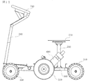
- FIG. 1 An example of the electric cart according to the present embodiment is shown in FIG.
- a pillar 700 of a chair (not shown) is fixed slightly behind the center bearing of the center frame 100 of the rocker bogie mechanism 1, and a top plate 710 for fixing the chair to the upper end of the pillar 700 is It is rotatably fixed about a support 700 as an axis.
- a handle 750 and its support 760 are fixed.
- an operation button for operating the traveling device may be provided.
- an operation button for example, an on-off button of a drive source, a reverse button to reversely rotate a driving wheel, a button to make traveling speed variable, a turn button, and a light on / off button when the traveling device has a light possible.
- the top plate 710 to which the chair is fixed may be provided with a vertical movement mechanism that makes its height variable, and in that case, the operation button also includes the operation button of the vertical movement mechanism of the top plate 710.
- the drive source 600 for driving the drive wheel 320 is provided with a control device, and controls the drive wheel 320 in response to the button operation.
- the controller reversely rotates the drive wheel.
- the traveling device moves rearward in the traveling direction.
- the turning button is operated, one of the left and right driving wheels is rotated forward, and the other is rotated reversely by the same amount as the rotation. This enables turning on the spot.
- the operation of the handle 750 is transmitted to the drive wheel 320 via an electrical signal or via a mechanical transmission mechanism.
- an electrical signal is used, the leftward or rightward movement is possible by changing the amount of rotation of the left and right drive wheels 320A and 320B according to the output of the sensor that detects the operation of the steering wheel. For example, when the handle 750 is rotated to the left, an electrical signal corresponding to the amount of rotation is transmitted to the control device of the drive source 600 to relatively increase the amount of rotation of the right drive wheel.
- the traveling apparatus of the present embodiment uses a structure in which traveling sections consisting of a pair of rocker bogie mechanisms are axially supported on both sides of the center frame, so that it is easy to get over the steps and get on and off, and maintain posture stability. it can.
- the center frame on which a chair on which a person mounts is fixed is kept horizontal, a comfortable ride can be obtained with less shaking.
- a backrest, elbow rest, foot rest, etc. may be provided to ensure the stability of the time.
- a novel rocker bogie mechanism and traveling device capable of securing stability and levelness in traveling on a rough ground are provided.
Landscapes
- Engineering & Computer Science (AREA)
- Chemical & Material Sciences (AREA)
- Combustion & Propulsion (AREA)
- Transportation (AREA)
- Mechanical Engineering (AREA)
- Handcart (AREA)
Abstract
La présente invention a trait à un mécanisme de bogie à bascule qui est mince et présente une structure dans laquelle un cadre central est prévu et une paire de bogies à bascule à déplacement indépendant sont disposés des deux côtés du cadre central. Chacun des bogies à bascule a une structure dans laquelle un cadre à bascule qui constitue le bogie à bascule est supporté de manière pivotante par le cadre central, et s'étend essentiellement horizontalement. L'utilisation de ce mécanisme de bogie à bascule en tant que chariot et le montage d'un corps principal sur le cadre central permettent de constituer un dispositif de déplacement qui a à la fois la force et la capacité de manipulation par rapport aux différences de niveau.
Priority Applications (2)
| Application Number | Priority Date | Filing Date | Title |
|---|---|---|---|
| PCT/JP2017/024505 WO2019008673A1 (fr) | 2017-07-04 | 2017-07-04 | Mécanisme de bogie à bascule et dispositif de déplacement |
| CN201780091262.5A CN110709314B (zh) | 2017-07-04 | 2017-07-04 | 摇臂转向架机构及行走装置 |
Applications Claiming Priority (1)
| Application Number | Priority Date | Filing Date | Title |
|---|---|---|---|
| PCT/JP2017/024505 WO2019008673A1 (fr) | 2017-07-04 | 2017-07-04 | Mécanisme de bogie à bascule et dispositif de déplacement |
Publications (1)
| Publication Number | Publication Date |
|---|---|
| WO2019008673A1 true WO2019008673A1 (fr) | 2019-01-10 |
Family
ID=64950666
Family Applications (1)
| Application Number | Title | Priority Date | Filing Date |
|---|---|---|---|
| PCT/JP2017/024505 WO2019008673A1 (fr) | 2017-07-04 | 2017-07-04 | Mécanisme de bogie à bascule et dispositif de déplacement |
Country Status (2)
| Country | Link |
|---|---|
| CN (1) | CN110709314B (fr) |
| WO (1) | WO2019008673A1 (fr) |
Families Citing this family (2)
| Publication number | Priority date | Publication date | Assignee | Title |
|---|---|---|---|---|
| JP7482837B2 (ja) * | 2021-06-18 | 2024-05-14 | 株式会社クボタ | 作業車 |
| CN113665846A (zh) * | 2021-08-31 | 2021-11-19 | 吉林大学 | 一种适用于深空巡视器移动的摇臂机构 |
Citations (5)
| Publication number | Priority date | Publication date | Assignee | Title |
|---|---|---|---|---|
| JPH10501495A (ja) * | 1994-03-15 | 1998-02-10 | キネティック リミテッド | 接続されたトーションバーをもつサスペンション |
| JP2014168971A (ja) * | 2013-03-01 | 2014-09-18 | Aichi Univ Of Technology | 車輪型移動車 |
| WO2016152966A1 (fr) * | 2015-03-24 | 2016-09-29 | 地方独立行政法人東京都立産業技術研究センター | Bogie à culbuteur |
| US20160297065A1 (en) * | 2015-04-03 | 2016-10-13 | Harris Corporation | Conformal suspension for unmanned ground vehicle |
| US20170020087A1 (en) * | 2011-12-19 | 2017-01-26 | Younis Technologies, Inc. | Robotic irrigation system |
Family Cites Families (3)
| Publication number | Priority date | Publication date | Assignee | Title |
|---|---|---|---|---|
| JP3559826B2 (ja) * | 2000-03-08 | 2004-09-02 | 独立行政法人理化学研究所 | 段差乗り越え可能な全方向移動車 |
| JP5240683B2 (ja) * | 2007-06-08 | 2013-07-17 | 独立行政法人 宇宙航空研究開発機構 | ロッカークローラを付加した走行機構 |
| CN201834132U (zh) * | 2010-09-30 | 2011-05-18 | 中山市隆成日用制品有限公司 | 含动力轮稳定贴地机构的电动代步车 |
-
2017
- 2017-07-04 WO PCT/JP2017/024505 patent/WO2019008673A1/fr active Application Filing
- 2017-07-04 CN CN201780091262.5A patent/CN110709314B/zh active Active
Patent Citations (5)
| Publication number | Priority date | Publication date | Assignee | Title |
|---|---|---|---|---|
| JPH10501495A (ja) * | 1994-03-15 | 1998-02-10 | キネティック リミテッド | 接続されたトーションバーをもつサスペンション |
| US20170020087A1 (en) * | 2011-12-19 | 2017-01-26 | Younis Technologies, Inc. | Robotic irrigation system |
| JP2014168971A (ja) * | 2013-03-01 | 2014-09-18 | Aichi Univ Of Technology | 車輪型移動車 |
| WO2016152966A1 (fr) * | 2015-03-24 | 2016-09-29 | 地方独立行政法人東京都立産業技術研究センター | Bogie à culbuteur |
| US20160297065A1 (en) * | 2015-04-03 | 2016-10-13 | Harris Corporation | Conformal suspension for unmanned ground vehicle |
Also Published As
| Publication number | Publication date |
|---|---|
| CN110709314B (zh) | 2022-06-21 |
| CN110709314A (zh) | 2020-01-17 |
Similar Documents
| Publication | Publication Date | Title |
|---|---|---|
| JP6708488B2 (ja) | ロッカーボギー機構及び走行装置 | |
| US10787217B2 (en) | Tilting mechanism for a wheeled vehicle | |
| WO2011074204A1 (fr) | Véhicule entraîné par un rouleau ventral | |
| WO2013051493A1 (fr) | Véhicule à alimentation électrique à deux roues arrière | |
| JP2019520266A (ja) | 原動機付車両の傾斜式前キャリッジおよび関連する原動機付車両 | |
| JPS637993B2 (fr) | ||
| IT201600071538A1 (it) | Veicolo a tre o piu' ruote basculanti, con sospensione a vincolo reattivo. | |
| JP2014061870A (ja) | 車両 | |
| WO2019008673A1 (fr) | Mécanisme de bogie à bascule et dispositif de déplacement | |
| JP6935610B1 (ja) | 車両 | |
| US9227685B2 (en) | Vehicle | |
| JP3286846B2 (ja) | クランク式車軸による懸架装置 | |
| WO2019082566A1 (fr) | Petit véhicule | |
| TWI737766B (zh) | 搖臂轉向架機構及行走裝置 | |
| WO2021131702A1 (fr) | Véhicule | |
| JPH11206817A (ja) | 車椅子用キャスタ | |
| JP5314176B1 (ja) | 三輪自転車 | |
| WO2012092182A1 (fr) | Vélo motorisé | |
| KR20140073368A (ko) | 틸팅 기능을 갖춘 멀티트랙 차량과 그를 위한 자세 안정화 장치 | |
| NL1035799C2 (en) | Tiltable tricycle. | |
| WO2019064857A1 (fr) | Véhicule à inclinaison | |
| WO2011065376A1 (fr) | Dispositif de suspension pour véhicule | |
| JP3498757B2 (ja) | 空気ばね式懸架装置 | |
| JP6784004B2 (ja) | スケートボード | |
| WO2021125348A1 (fr) | Véhicule |
Legal Events
| Date | Code | Title | Description |
|---|---|---|---|
| 121 | Ep: the epo has been informed by wipo that ep was designated in this application |
Ref document number: 17916654 Country of ref document: EP Kind code of ref document: A1 |
|
| NENP | Non-entry into the national phase |
Ref country code: DE |
|
| 122 | Ep: pct application non-entry in european phase |
Ref document number: 17916654 Country of ref document: EP Kind code of ref document: A1 |
|
| NENP | Non-entry into the national phase |
Ref country code: JP |