WO2019008673A1 - Rocker bogie mechanism and travel device - Google Patents
Rocker bogie mechanism and travel device Download PDFInfo
- Publication number
- WO2019008673A1 WO2019008673A1 PCT/JP2017/024505 JP2017024505W WO2019008673A1 WO 2019008673 A1 WO2019008673 A1 WO 2019008673A1 JP 2017024505 W JP2017024505 W JP 2017024505W WO 2019008673 A1 WO2019008673 A1 WO 2019008673A1
- Authority
- WO
- WIPO (PCT)
- Prior art keywords
- frame
- rocker
- wheel
- bogie
- traveling
- Prior art date
Links
Images


Classifications
-
- B—PERFORMING OPERATIONS; TRANSPORTING
- B62—LAND VEHICLES FOR TRAVELLING OTHERWISE THAN ON RAILS
- B62D—MOTOR VEHICLES; TRAILERS
- B62D57/00—Vehicles characterised by having other propulsion or other ground- engaging means than wheels or endless track, alone or in addition to wheels or endless track
- B62D57/02—Vehicles characterised by having other propulsion or other ground- engaging means than wheels or endless track, alone or in addition to wheels or endless track with ground-engaging propulsion means, e.g. walking members
-
- B—PERFORMING OPERATIONS; TRANSPORTING
- B62—LAND VEHICLES FOR TRAVELLING OTHERWISE THAN ON RAILS
- B62D—MOTOR VEHICLES; TRAILERS
- B62D61/00—Motor vehicles or trailers, characterised by the arrangement or number of wheels, not otherwise provided for, e.g. four wheels in diamond pattern
- B62D61/10—Motor vehicles or trailers, characterised by the arrangement or number of wheels, not otherwise provided for, e.g. four wheels in diamond pattern with more than four wheels
Definitions
- the present invention relates to a locker bogie mechanism, and more particularly to a locker bogie mechanism suitable for a person-carrying traveling device.
- a rocker bogie mechanism is adopted as a mechanism for traveling on uneven terrain with irregularities (for example, Patent Document 1).
- the rocker bogie mechanism has a structure in which two links (rocker and bogie) are flexibly connected to each other, and a wheel unit is connected to the lower end of each link.
- Patent Document 1 describes an omnidirectional mobile vehicle that travels with a total of six driving wheels, with the two links that make up the rocker bogie mechanism each being rectangular and the wheel units attached to the two opposing sides thereof.
- the locker-bogie mechanism has, for example, a locker and a bogie even when a wheel connected to a bogey located forward in the traveling direction runs onto a step (convex portion) or falls into a step (concave portion).
- a wheel connected to a bogey located forward in the traveling direction runs onto a step (convex portion) or falls into a step (concave portion).
- Patent Document 2 proposes a structure in which a rear caster is fixed to a chair portion and a driving wheel and a front caster can be pivoted with respect to the chair portion in a wheelchair provided with castors before and after the drive wheel. This structure makes it possible to get on and off a step or make a turn around the drive wheel.
- a traveling vehicle using a conventional rocker bogie mechanism as described in Patent Document 1 has a structure in which a frame (link) itself located at the center in the left-right direction is bent.
- a frame (link) itself located at the center in the left-right direction is bent.
- Such a structure is less of a problem as a traveling vehicle without a person mounted, but when a seat or the like for mounting a person is fixed to a frame, the levelness of the seat can not be maintained. In other words, people who sit on the seat will be shaken back and forth as they get over the steps, which makes them extremely unstable.
- the rocker bogie mechanism of the present invention has a structure in which a center frame is provided and a pair of independently traveling rocker bogies are disposed on both sides of the center frame. Further, each rocker bogie has a structure in which a rocker frame constituting it is pivotally supported by the center frame so as to be pivotable and basically extends in a horizontal direction.
- the traveling vehicle of the present invention also includes a main body and a carriage, and the carriage has the above-mentioned locker-bogie mechanism.
- the body is fixed to the center frame.
- FIG. 1 The perspective view of the rocker bogie mechanism of the first embodiment Top view of the rocker bogie mechanism of FIG. 1 Side view of the rocker bogie mechanism of FIG. 1 Perspective view of a rocker frame with wheels fixed
- An exploded perspective view of the bogey frame (A), (b) is a figure which respectively shows the example of a change of a wheel
- the perspective view which shows the principal part (stabilizer part) of FIG. 1 (A-1)-(g-2) is a figure explaining operation
- (A) is a figure which shows the rocker-bogie mechanism of 2nd embodiment
- (b) is a figure which shows the example of a change.
- (A), (b) is a figure explaining the function of the rocker-bogie mechanism of 2nd embodiment.
- the rocker bogie mechanism of the present embodiment has a center frame and a pair of traveling portions mounted symmetrically with respect to the center frame.
- the pair of traveling parts are respectively a rocker frame supported by a shaft at the center frame, a bogie frame pivotally supported at one end (first end) of the rocker frame, and the other end of the rocker frame
- the second end) and the two ends of the bogie frame are respectively provided with a first wheel, a second wheel and a third wheel pivotally supported.
- Each rocker frame of the pair of traveling portions has a horizontally extending frame portion. That is, each rocker frame has two frame portions bent so as to be separated in the horizontal direction between the respective first end portions and between the respective second end portions with respect to the position pivotally supported by the center frame. .
- the rocker bogie mechanism of the present embodiment will be specifically described with reference to the drawings.
- the direction in which the rocker bogie mechanism moves by forward rotation of the drive wheel is referred to as the traveling direction or the longitudinal direction
- the horizontal direction orthogonal to the traveling direction is referred to as the lateral direction.
- the side where the wheels come in contact is down, and the opposite side is up.
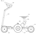
- the rocker bogie mechanism 1 of the present embodiment has a center frame 100 and a pair of traveling portions 200A and 200B attached to the left and right sides of the center frame 10.
- the structures of the left and right traveling units 200A and 200B are symmetrical with respect to the center frame 1, and in the following description, the suffixes A and B are omitted from the reference numerals of the both and the respective constituent elements. Use numbers.
- the center frame 100 is made of a member whose longitudinal direction is the traveling direction, and functions as a keel of the rocker bogie mechanism 1 of the present embodiment.
- a center bearing portion 115 is formed substantially at the center of the center frame 100 in the longitudinal direction, and a main shaft 500 for mounting the traveling portions 200A and 200B is fixed to the center bearing portion 115.
- the traveling portions 200A and 200B themselves constitute a rocker bogie mechanism, and are respectively pivotally supported by a rocker frame 210 pivotally supported by the main shaft 500 and one end (first end) 211 of the rocker frame.
- the traveling portions 200A and 200B can be independently rotated because each rocker frame 210A and 210B is pivotally supported with respect to the center frame 100. As a result, only one side of the traveling portion can ride on the step or get off the step.
- the rocker frames 210A and 210B are substantially parallel to the horizontal surface and substantially in the horizontal surface It has a bent shape. That is, as shown in FIG. 3, a polygon connecting a first end portion 211A of the locker frame 210A, a second end portion 212A, and a portion (referred to as an intermediate portion) 213A connected to the center frame 100 and a locker frame 210B.
- the polygon connecting the first end portion 211B, the second end portion 212B, and the middle portion 213B is substantially parallel to the flat ground surface.
- a first wheel 310 pivotally supported by 330 and the rocker frame 210 is a driven wheel, the former being a front wheel and the latter being a rear wheel.
- the bogie frame 220 is provided with a drive source attachment portion for mounting a drive source of the second wheel 320 which is a drive wheel, for example, a motor.
- the rocker bogie mechanism 1 of the present embodiment is provided with one or more stabilizers 400 between the traveling parts 200A and 200B.
- the stabilizer 400 has a function of stabilizing the movement of the traveling units 200A and 200B which can rotate independently with respect to the center frame 100.
- the center frame 100 is a rectangular solid member whose longitudinal direction is the traveling direction.
- the longitudinal length of the member is approximately, but not limited to, the distance between the front and rear wheels.
- a center bearing portion 115 which is a bearing of the main shaft 500 for pivotally supporting the rocker frames 210A and 210B is fixed.
- support members 410 for supporting the stabilizer 400 are fixed at two places between the center bearing portion 115 and both ends. The structure of the support member 410 will be described later.
- the rocker frame 210 includes, as main components, a rocker bearing portion 215 and frame portions 216 and 217 fixed to both sides (front and rear sides) of the rocker bearing portion 215 in the front-rear direction. And. Further, a rocker frame side boge bearing portion 218 combined with a bogey bearing portion on a bogie frame side described later is fixed to an end of the front side frame portion 216 (a first end 211 of the rocker frame 210).
- the rocker frame side bogie bearing portion 218 is referred to as a first bogie bearing portion
- the bogie bearing portion on the bogie frame side is referred to as a second bogie bearing portion.
- the end of the rear frame portion 217 (the second end 212 of the rocker frame 210) is provided with a structure for attaching the first wheel 310.
- the rocker frames 210A and 210B of the traveling units 200A and 200B are disposed with respect to the center frame 100 so that the center bearing unit 115 of the center frame 100 is sandwiched by the rocker bearing units 215A and 215B, and the main shaft 500 corresponds to each bearing unit 215A, It is pivotally supported by the center frame 100 by penetrating and fixing to 115, 215B.
- the frame portions 216 and 217 are cylindrical members and have a structure bent at two points.
- the frame portion 216 is fixed to the rocker bearing portion 215 so that the axis of the cylinder is in a direction orthogonal to the main shaft 500, is bent forward forward near its fixed end, and is further fixed to the bogie bearing portion 225 It is bent forward (in a direction parallel to the longitudinal direction).
- the frame portion 217 is also fixed to the rocker bearing portion 215 so that the axis of the cylinder is in a direction orthogonal to the main shaft 500, and bent backward obliquely in the vicinity of its fixed end to attach the first wheel 310 It is bent backward (in a direction parallel to the front-rear direction) near the end.
- the frame portion 217 has a longer length in the front-rear direction than the frame portion 216 to which the bogie frame 220 is attached, whereby the two wheels (front wheel 330, driving wheel 320) fixed to both ends of the bogie frame 220 and the frame portion
- the intervals of the front and rear directions of the first wheels 310 attached to the ends 217 are substantially equal.
- the rocker frame 210 is arranged such that the wheels 310 and the bogie frame 220 connected thereto are horizontally spaced apart from one another without increasing their height, as shown in FIG. Can take
- known means such as screwing, screws (bolts) and welding can be used.
- the structure for attaching the first wheel 310 at the end of the frame portion 217 is different depending on the type of the first wheel 310 which is a driven wheel, but in the illustrated embodiment, an omni wheel is adopted as the first wheel 310
- the structure of the case is shown. That is, the end of the frame portion 217 is formed of a plate member 219 that fixes an omni plate that supports the axis (omni axis 335) of the omni wheel.
- the plate-like member 219 may be formed integrally with the cylindrical member constituting the frame portion 217, or a plate-like member as a separate part may be screwed, screwed, welded, etc. to the cylindrical member. And may be integrated.
- the bogie frame 220 includes, as main components, a bogie bearing portion 225 (second bogie bearing portion) and a frame portion 226 fixed to both sides (front and rear sides) in the front-rear direction. , 227.
- the bogie frame 220 is rotatably fixed to the rocker frame 210 by a common shaft 510 (FIGS. 1 and 2) passing through the second bogie bearing portion 225 and the first bogie bearing portion 215.
- the front frame portion 226 is a cylindrical member, and the end 221 thereof is provided with a structure for attaching the third wheel (front wheel) 330.
- This structure is similar to the structure of the end portion of the frame portion 217 of the locker frame 210, and can adopt various structures depending on the wheels to be attached, and in this case, it comprises angular members 229 for fixing the omni wheel ing.
- the frame portion 227 on the rear side is a cylindrical member in which a bending portion is formed, and a horizontal portion 227a extending in a direction orthogonal to the shaft 510 and a bending portion 227b bent upward with respect to the second bogie bearing portion 225 Have.
- the bending portion 227 b is provided with a second wheel 320 which is a driving wheel and a mounting portion 610 for mounting the driving source 600.
- the drive source 600 is, for example, a motor, and the rotation shaft of the second wheel 320 is fixed to its rotor directly or through a power transmission mechanism.
- the mounting portion 610 is not particularly limited as long as it has a structure for supporting the second wheel 320 configured integrally with the drive source 600 and fixing it to the frame portion 227 in this way, but here it is fixed to the frame portion 227 A structure is adopted in which a part of the motor is sandwiched and fixed by the fixing block 611 and the cover block 612 which is removably fixed to the fixing block.
- the drive source 600 is a motor
- the drive source 600 is connected to a power supply (not shown) and is provided with a switch for turning the motor on and off.
- the first wheel 310 and the third wheel 330 are driven wheels that follow the drive wheels, and employ omni wheels that can rotate in all directions.
- the omni wheel has a structure in which a plurality of rotating bodies that rotate around the circumferential direction are attached along the circumference of a disk-shaped wheel, and it is known that a single disk or a plurality of disks are stacked. There is.
- an omni wheel is used in which double disks are stacked so that rotating bodies arranged on the circumference of the respective disks alternate. By using the omni wheel, it is possible to make the traveling device excellent in space availability and linear stability.
- the driven wheel is not limited to the omni wheel, and a caster or the like can also be used.
- the case where only the center wheel (the second wheel 320) among the three wheels respectively on the left and right sides is the drive wheel is shown, but all wheels may be drive wheels, or the center wheel and the front or rear wheel One of them may be a driving wheel.
- the front wheel is not a driving wheel, it is difficult to get over when the step approaches deformation of the wheel, but it is possible to easily get over a step near the radius of the wheel by using the driving wheel.
- a moving wheel caster, an in-wheel motor as shown in FIG. 6A, or the like may be adopted.
- the front wheel 330 is disposed on the same line as the second wheel (drive wheel) 320 by the bogie frame 220, as shown in FIG. You may make it a driving wheel.
- the stabilizer 400 is a mechanism for preventing twisting of the frames of the left and right traveling units 200A and 200B which can operate independently, and ensuring the stability of the operation, and as shown in FIG. Mainly, it consists of a rod-like member 450 which is bridged between two traveling parts 200A and 200B and a mechanism for supporting it.
- the stabilizer 400 is provided in two places between the first end portions 211A and 211B of the rocker frames 210A and 210B and between the second end portions 212A and 212B, but the basics are The same structure is the same, and the following description is common to both unless otherwise stated.
- the rod-like member 450 is a member (a torsion bar) formed of a metal rod such as steel, and the diameter thereof varies depending on the size and weight of the rocker bogie mechanism 1 or the traveling vehicle, but corresponds to the height difference between the left and right wheels. It has a rigidity that can be bent.
- a block (a peristaltic member) 420 is fixed to a longitudinal center of the rod-like member 450.
- the support mechanism of the rod-like member 450 includes a support member (shaft support member) 410 on the center frame 100 side and a support member (430) on the rocker frame 220 side.
- the support member 410 on the center frame 100 side is a U-shaped member having a U-shaped cross section including a bottom surface, a top surface, and a vertical surface connecting them, and the bottom surface is fixed to the top surface of the center frame 100 by a bolt or the like.
- a pivoting member 420 fixed to a central portion of the rod member 450 is pivotally supported by a shaft 440.
- the direction of the shaft 440 pivotally supporting the peristaltic member 420 is orthogonal to the vertical plane, which allows the peristaltic member 420 to rotate in a plane parallel to the vertical plane.
- the pivotal movement of the peristaltic member 420 Is limited to a predetermined angular range, for example ⁇ 15 degrees.
- a predetermined angular range for example ⁇ 15 degrees.
- the first end portion 211 and the second end portion 211 of the left and right rocker frames 210A and 210B are holders for slidably supporting the rod-like member 450 as a support member for the rod-like member 450.
- 430, 430 are fixed.
- the holder 430 has a shape in which two members having an L-shaped cross section are combined upside down and in the opposite direction, and a through hole is formed in the upper vertical surface, and the rod member 450 is made to penetrate through this hole. To support.
- this supporting structure even if the height difference between the left and right wheels is caused and the rod member 450 is bent, the end of the rod member 450 is shifted in the direction shown by the arrow in the figure to maintain the width between the left and right wheels. Can.
- the pair of traveling portions 200A and 200B disposed with the center frame 100 interposed therebetween is rotatably fixed to the center frame 100 independently of each other. For this reason, when a part (or all) of the wheels on one of the running parts rides on or off the step, the frame twists and the running posture becomes unstable without maintaining the verticality of the wheels. There is sex.
- the stabilizer 400 having the above-described structure, it is possible to prevent the twisting of the pair of traveling portions 200A and 200B (wheels) that can rotate independently, and to maintain the stability during traveling. Further, by adopting a torsion bar as the stabilizer 400, it is possible to obtain the effect of preventing twisting and maintaining the stability with a simple and lightweight structure without using a heavy mechanism such as a differential gear.
- FIG. 7 shows an example in which the stabilizer 400 is provided at two places between the two end portions of the rocker frame, the position of providing the stabilizer and the number of the stabilizer are not limited to this embodiment.
- FIGS. 8 (a-1) to 8 (g-1) are side views of the rocker bogie mechanism 1 when the rocker bogie mechanism 1 traveling with the third wheel 330 as the front wheel rides on and off the step S (a side view ).
- (a-2) to (g-2) show a state in which only one of the pair of traveling portions gets on and off the step S corresponding to (a-1) to (g-1). It is the figure (front view) seen from the front (front side) of 1.
- FIG. 8 (a-1) to 8 (g-1) are side views of the rocker bogie mechanism 1 when the rocker bogie mechanism 1 traveling with the third wheel 330 as the front wheel rides on and off the step S (a side view ).
- (a-2) to (g-2) show a state in which only one of the pair of traveling portions gets on and off the step S corresponding to (a-1) to (g-1). It is the figure (front view) seen from the front (front side) of 1.
- the rocker bogie mechanism 1 travels forward as shown by the arrow in the figure.
- the third wheel (front wheel) 330 and the second wheel (driving wheel) 320 In this state, the center frame 100 and the locker frame 210 are kept horizontal.
- the step S to be overcome by the rocker bogie mechanism 1 is convex, and the width of the convex portion is narrower than the distance between the front wheel 330 and the drive wheel 320.
- the front wheel 330 riding on the step S1 is flat at a lower position than the convex portion when the drive wheel 320 climbs on the step S1 (convex portion). I'm getting down to face G.
- the front wheel 330 can be installed on the flat surface G without being affected by the position elevation of the drive wheel 320 due to the free rotation of the bogie frame 220 in the counterclockwise direction.
- the rear wheel 310 can be maintained in contact with the flat surface G by free rotation of the rocker frame 210 in the clockwise direction. In any state, the difference in height between the wheels generated in each state is absorbed by the rotation of the bogie frame 220 and the rocker frame 210, and the horizontality of the center frame 100 is maintained.
- FIGS. 8 (e-1) to 8 (g-1) show cases where the rocker bogie mechanism 1 traveling on the flat surface G descends from the step S2 whose height is lower than that of the flat surface G.
- FIG. Also in these cases, as in the case of traveling the convex step S2, it is possible to go down or over the step while maintaining the horizontality of the center frame 100.
- FIG. 8 (g-1) even when traveling along a recess where the distance between the steps S is narrower than the width between the wheels, the difference in height between the front wheel 330 and the drive wheel 320 and the corresponding bogey frame
- the pivoting of 220 and the difference in height between the driving wheel 320 and the rear wheel 310 and the pivoting of the corresponding rocker frame 210 are described in FIGS. 8 (b-1) and 8 (f-1), respectively.
- any of the wheels can travel while maintaining the grounded state without floating from the ground. Thereby, the power from the drive source 400 is efficiently transmitted to all the wheels.
- the operation of the stabilizer 400 during traveling will be described below with reference to drawings (a-2) to (g-2) on the right side of FIG.
- the right side is described as the traveling unit 200A
- the left side is described as the traveling unit 200B.
- FIGS. 8 (b-1) and 8 (b-2) when only the front wheel 330A of the traveling unit 200A rides on the step S, the traveling units 200A and 200B operate independently of each other. Becomes possible.
- the rod member 450 exerts a force to press the drive wheel 320A against the ground contact surface by its rigidity, so that the posture becomes unstable due to excessive rotation or left-right inclination of the rocker frame 210A by the momentum of the drive wheel 320A being lifted. Can be prevented.
- the rocker bogie mechanism of this embodiment is characterized by the structure which pivotally supported the rocker frame by the running part which consists of a rocker bogie mechanism on both sides of a center frame.
- the present invention is not limited to the above embodiment, and various modifications such as deletion or addition of non-essential elements or deformation of constituent elements are possible. Some variations are listed below.
- the rocker bogie mechanism of the present embodiment is characterized based on the rocker bogie mechanism of the first embodiment and further provided with means for enhancing the resistance of the torsional stress applied to the frame by the load.
- the other configuration is the same as that of the first embodiment.
- the rocker bogie mechanism of the present embodiment will be described using FIGS. 9 and 10.
- FIG. 9 is a plan view of the rocker bogie mechanism of the present embodiment
- FIG. 10 is a view for explaining the operation thereof.
- the same elements as those of the rocker bogie mechanism of the first embodiment are denoted by the same reference numerals, and the redundant description will be omitted.
- the stabilizer 480 is disposed at the end of the frame portion 227 of the bogie frame 220 which is the mounting portion of the motor.
- the tip of the frame portion 227 is further bent, and a stabilizer 480 is attached using this structure.
- a rod-like member (tension bar) similar to the stabilizer 400 (450) disposed forward and backward from the center can be employed.
- the supporting member of the stabilizer 480 is abbreviate
- the reinforcing plate 490 may be fixed to the bogie frame 220 supporting the motor 600, and the stabilizer 480 which is a rod-like member may be supported by the left and right reinforcing plates 490.
- the load applied to the center frame is the outermost wheel. It takes to In particular, the load applied to the second wheel (drive wheel) located at the center is the largest, so the load (the frame portion 216 of the rocker frame and the frame portion 227 of the bogie frame) where the drive wheel and motor are connected Torsional stress is applied. For this reason, the upper part of the motor attached to the frame part 227 falls inward, and the drive wheel 320 is easily opened in a figure of eight.
- the stabilizer 480 when the stabilizer 480 is disposed at the center as in the present embodiment, as shown in FIG. 10 (b), when a load is applied to the center frame 100, the stabilizer 480 bends downward along with its displacement. An outward force is applied to the tip of the bogie frame 220 (frame portion 227) supporting both ends. This resists the force of tilting the motor inward and prevents the wheels from opening in a C shape.
- the diameter of the frame itself is increased, the thickness is increased, and the support is reinforced. Can be adopted.
- a reinforcing frame or a reinforcing frame which becomes a brace between a portion pivotally supported by the center frame 100 and each end 211, 212 or A reinforcing plate 219 or the like may be added.
- the reinforcing plate 219 is fixed to the rocker bearing portion 215 and the first bogie bearing portion 218 of the rocker frame 210, and reinforces the portion of the rocker frame 210 most likely to be loaded.
- the second bogie bearing portion 225 and the frame portions 226 and 227 fixed to both sides thereof may be reinforced by a reinforcing plate.
- the rocker frame and the bogie rocker frame can solve the problem of the structure that may occur due to being mounted in the horizontal direction with respect to the center frame, and can provide a structurally robust rocker bogie mechanism.
- each frame constituting the rocker bogie mechanism may be a shape different from that of the embodiment described above. It is also possible to add members to reinforce the
- the locker frame 210 is shown to include two frame portions 216 and 217 having a portion bent in an oblique front and an oblique rear, an arc frame or a frame bent in a direction perpendicular to the traveling direction is shown. Etc. can also be adopted.
- bogie frame 220 it is also possible to change the distance between the front wheels and the drive wheels by changing the bending direction appropriately.
- the locker bogie mechanism of the present invention can be applied to various traveling devices such as a person-free mobile robot (robot), a person-mounted electric cart, a wheelchair, and the like, and in particular, the horizontality of the center frame is maintained.
- the present invention can be suitably applied to a traveling apparatus for carrying a person by taking advantage of the feature of being a mechanism that maintains a low stable posture.
- an electric cart in which a chair on which a person sits and a handle for operation are attached to the above-described rocker bogie mechanism 1 will be described as an example of a traveling device.
- the electric wheelchair has a standard defined by JIS (total length: 1200 mm, full width: 700 mm, total height: 1090 mm, step difference: 40 mm), and the size of the rocker bogie mechanism 1 and the size of the chair attached thereto are within these standards. It is the size to enter.
- each frame (rocker frame 210 and bogie frame 220) of rocker bogie mechanism 1 has its bottom surface (lower end) at the position of the axis (center) of drive wheel 320. It is preferable that the range from the position of the shaft to the thickness of the frame be an acceptable range.
- the lower end of the frame is lower than the axis of the wheel, it is difficult to get over a step higher than the radius of the wheel, and the lower end is likely to contact the step.
- the height of a standard sidewalk is 200 mm
- the step on the slope when riding up from the road to the sidewalk is about 50 mm
- the height near the center of the slope is about 100 mm.
- the height of the frame be about 120 mm.
- a load from above is applied to the upper side of the drive wheel, and a torsional stress is applied to the inside of the frame.
- the clearance between the load on the center frame and the locker frame 210 or the bogie frame 220 is narrowed, and the tolerance when the frame is rotated is also narrowed due to overcoming of a step or the like.
- FIG. 1 An example of the electric cart according to the present embodiment is shown in FIG.
- a pillar 700 of a chair (not shown) is fixed slightly behind the center bearing of the center frame 100 of the rocker bogie mechanism 1, and a top plate 710 for fixing the chair to the upper end of the pillar 700 is It is rotatably fixed about a support 700 as an axis.
- a handle 750 and its support 760 are fixed.
- an operation button for operating the traveling device may be provided.
- an operation button for example, an on-off button of a drive source, a reverse button to reversely rotate a driving wheel, a button to make traveling speed variable, a turn button, and a light on / off button when the traveling device has a light possible.
- the top plate 710 to which the chair is fixed may be provided with a vertical movement mechanism that makes its height variable, and in that case, the operation button also includes the operation button of the vertical movement mechanism of the top plate 710.
- the drive source 600 for driving the drive wheel 320 is provided with a control device, and controls the drive wheel 320 in response to the button operation.
- the controller reversely rotates the drive wheel.
- the traveling device moves rearward in the traveling direction.
- the turning button is operated, one of the left and right driving wheels is rotated forward, and the other is rotated reversely by the same amount as the rotation. This enables turning on the spot.
- the operation of the handle 750 is transmitted to the drive wheel 320 via an electrical signal or via a mechanical transmission mechanism.
- an electrical signal is used, the leftward or rightward movement is possible by changing the amount of rotation of the left and right drive wheels 320A and 320B according to the output of the sensor that detects the operation of the steering wheel. For example, when the handle 750 is rotated to the left, an electrical signal corresponding to the amount of rotation is transmitted to the control device of the drive source 600 to relatively increase the amount of rotation of the right drive wheel.
- the traveling apparatus of the present embodiment uses a structure in which traveling sections consisting of a pair of rocker bogie mechanisms are axially supported on both sides of the center frame, so that it is easy to get over the steps and get on and off, and maintain posture stability. it can.
- the center frame on which a chair on which a person mounts is fixed is kept horizontal, a comfortable ride can be obtained with less shaking.
- a backrest, elbow rest, foot rest, etc. may be provided to ensure the stability of the time.
- a novel rocker bogie mechanism and traveling device capable of securing stability and levelness in traveling on a rough ground are provided.
Abstract
This rocker bogie mechanism is thin and has a structure in which a center frame is provided and a pair of independently traveling rocker bogies are disposed on both sides of the center frame. Each of the rocker bogies has a structure in which a rocker frame that constitutes the rocker bogie is pivotably supported by the center frame, and extends basically horizontally. Using this rocker bogie mechanism as a truck and mounting a main body on the center frame makes it possible to constitute a travel device that has both strength and handling ability with respect to level differences.
Description
本発明はロッカーボギー機構に関し、特に人を乗せる走行装置に好適なロッカーボギー機構に関する。
BACKGROUND OF THE INVENTION 1. Field of the Invention The present invention relates to a locker bogie mechanism, and more particularly to a locker bogie mechanism suitable for a person-carrying traveling device.
現在広く用いられている4輪の電動カートは、段差において4輪のいずれかが接地せず浮いてしまうため、移動できなくなったり転倒したり事故が多い。また、その場での旋回ができないため狭い道での進路変更などが困難である、等の問題がある。
Currently, widely used four-wheeled electric carts are not movable or fall over, as any of the four wheels can not float on the step and float. In addition, there is a problem that it is difficult to change the course on a narrow road because it is impossible to turn on the spot.
一方、ロボットなどの自走車の分野では、凹凸のある不整地を走行する機構として、ロッカーボギー機構が採用されている(例えば、特許文献1)。ロッカーボギー機構は、2つのリンク(ロッカーとボギー)を互いに屈曲可能に連結し、それぞれのリンクの下端に車輪ユニットを連結した構造を有する。特許文献1には、ロッカーボギー機構を構成する2つのリンクをそれぞれ矩形とし、その対向する2辺に車輪ユニットを取り付け、合計6つの駆動輪で走行する全方向移動車が記載されている。
On the other hand, in the field of a mobile vehicle such as a robot, a rocker bogie mechanism is adopted as a mechanism for traveling on uneven terrain with irregularities (for example, Patent Document 1). The rocker bogie mechanism has a structure in which two links (rocker and bogie) are flexibly connected to each other, and a wheel unit is connected to the lower end of each link. Patent Document 1 describes an omnidirectional mobile vehicle that travels with a total of six driving wheels, with the two links that make up the rocker bogie mechanism each being rectangular and the wheel units attached to the two opposing sides thereof.
ロッカーボギー機構は、このような構造により、例えば、走行方向の前方に位置するボギーに連結した車輪が段差(凸部)に乗り上げた場合或いは段差(凹部)に落ちた場合にも、ロッカーとボギーとが屈曲することで、全ての車輪が接地した状態が保たれ、段差走行時の安定性を確保することができる。
With such a structure, the locker-bogie mechanism has, for example, a locker and a bogie even when a wheel connected to a bogey located forward in the traveling direction runs onto a step (convex portion) or falls into a step (concave portion). By bending, the state in which all the wheels are in contact with the ground can be maintained, and stability during traveling on a step can be ensured.
また特許文献2には、駆動輪の前後にキャスターを設けた車いすにおいて、後キャスターを椅子部分に固定し、駆動輪と前キャスターを椅子部分に対し搖動可能にした構造が提案されている。この構造により、段差の乗り降りや駆動輪を中心とする旋回などを可能にしている。
Further, Patent Document 2 proposes a structure in which a rear caster is fixed to a chair portion and a driving wheel and a front caster can be pivoted with respect to the chair portion in a wheelchair provided with castors before and after the drive wheel. This structure makes it possible to get on and off a step or make a turn around the drive wheel.
特許文献1に記載されるような、従来のロッカーボギー機構を用いた走行車は、その左右方向の中心に位置するフレーム(リンク)自体が屈曲する構造を有している。このような構造は人を搭載しない走行車としては問題が少ないが、人を搭載するための座部等をフレームに固定した場合、座部の水平性を保つことができない。すなわち座部に載った人は段差を乗り越える際に前後に揺さぶられることになり、きわめて安定性が悪いことになる。
A traveling vehicle using a conventional rocker bogie mechanism as described in Patent Document 1 has a structure in which a frame (link) itself located at the center in the left-right direction is bent. Such a structure is less of a problem as a traveling vehicle without a person mounted, but when a seat or the like for mounting a person is fixed to a frame, the levelness of the seat can not be maintained. In other words, people who sit on the seat will be shaken back and forth as they get over the steps, which makes them extremely unstable.
また特許文献2に記載されるような機構では、後キャスターは椅子部分に固定されているため、後キャスターが段差を乗り越えるとき或いは段差を降りるときに、その衝撃が直接椅子部分に伝わり、快適なすわり心地ではない。また座部の水平性を保つことが難しい。走行車(車いす)のすわり心地や水平性を保つために、緩衝装置を介在させることも考えられるが、その場合には、座面までの高さが高いものとなり、高さが制限される走行車には適用できない。また高さの増加は姿勢の安定性を損ねる。
Further, in the mechanism as described in Patent Document 2, since the rear caster is fixed to the chair portion, when the rear caster gets over the step or gets down from the step, the impact is directly transmitted to the chair portion, which is comfortable. I'm not comfortable. It is also difficult to maintain the levelness of the seat. In order to maintain the comfort and levelness of the traveling vehicle (wheelchair), it is also conceivable to intervene a shock absorber, in which case the height to the seat surface becomes high and the height is limited Not applicable to cars. An increase in height also impairs the stability of the posture.
本発明は、強度と段差に対する走破性を併せ持つ薄型ロッカーボギー機構を提供することを課題とする。またこのような薄型ロッカーボギー機構を適用することで、居住性と操作性を両立した新規な走行装置を提供することを課題とする。
An object of the present invention is to provide a thin rocker bogie mechanism having both strength and runnability with respect to steps. Another object of the present invention is to provide a novel traveling device that achieves both comfort and operability by applying such a thin rocker bogie mechanism.
上記課題を解決するため、本発明のロッカーボギー機構は、センターフレ-ムを設け、独立して走行する一対のロッカーボギーをセンターフレームの両側に配置した構造を持つ。また各ロッカーボギーは、それを構成するロッカーフレームがセンターフレームに軸支され回動可能であるとともに、基本的に水平方向に延びた構造を持つ。
In order to solve the above problems, the rocker bogie mechanism of the present invention has a structure in which a center frame is provided and a pair of independently traveling rocker bogies are disposed on both sides of the center frame. Further, each rocker bogie has a structure in which a rocker frame constituting it is pivotally supported by the center frame so as to be pivotable and basically extends in a horizontal direction.
また本発明の走行車は、本体と台車とを備え、台車が上述のロッカーボギー機構を有する。本体はセンターフレームに固定される。
The traveling vehicle of the present invention also includes a main body and a carriage, and the carriage has the above-mentioned locker-bogie mechanism. The body is fixed to the center frame.
センターフレームに対し両側に一対のロッカーボギー機構を軸支した構造とすることで、一方のロッカーボギー機構が段差を乗り越え、乗り降りする際にも安定した姿勢を保って走行することが可能であり、またロッカーボギー機構による段差乗り越えや乗り降り時においてもセンターフレーム自体の水平性を保つことができる。さらにロッカーボギー機構を構成するロッカーフレームが延びる方向を水平方向とすることで、全体的な高さの増加を抑えることができる。これにより人が載る走行装置に適用したときに、安定した走行性を確保することができる。
By having a structure in which a pair of rocker bogie mechanisms are pivotally supported on both sides with respect to the center frame, it is possible to travel while maintaining a stable posture when one rocker bogie mechanism climbs over a step and gets on / off. In addition, it is possible to maintain the horizontality of the center frame itself even when climbing over a step or getting on and off due to the locker bogie mechanism. Further, by setting the direction in which the locker frame forming the locker bogie mechanism extends in the horizontal direction, an increase in the overall height can be suppressed. Thereby, when applied to a traveling device on which a person stands, stable traveling performance can be secured.
本発明のロッカーボギー機構と走行車が備えるその他の特徴と効果は、以下の実施形態において説明する。
Other features and effects of the rocker bogie mechanism of the present invention and the traveling vehicle will be described in the following embodiments.
まず本発明のロッカーボギー機構の実施形態を説明する。
First, an embodiment of the rocker bogie mechanism of the present invention will be described.
<第一の実施形態>
本実施形態のロッカーボギー機構は、センターフレームと、前記センターフレームに対し対称に取り付けられた一対の走行部とを有する。一対の走行部は、それぞれ、センターフレームに軸により支持されたロッカーフレームと、ロッカーフレームの一方の端部(第一端部)に軸支されるボギーフレームと、ロッカーフレームの他方の端部(第二端部)及びボギーフレームの2つの端部に、それぞれ、軸支される第一車輪、第二車輪及び第三車輪と、を備える。 First Embodiment
The rocker bogie mechanism of the present embodiment has a center frame and a pair of traveling portions mounted symmetrically with respect to the center frame. The pair of traveling parts are respectively a rocker frame supported by a shaft at the center frame, a bogie frame pivotally supported at one end (first end) of the rocker frame, and the other end of the rocker frame The second end) and the two ends of the bogie frame are respectively provided with a first wheel, a second wheel and a third wheel pivotally supported.
一対の走行部の各ロッカーフレームは、水平方向に延びるフレーム部を有する。即ち、各ロッカーフレームは、センターフレームに軸支される位置に対し、各第一端部間及び各第二端部間が、それぞれ、水平方向に離間するように屈曲した2つのフレーム部を有する。
Each rocker frame of the pair of traveling portions has a horizontally extending frame portion. That is, each rocker frame has two frame portions bent so as to be separated in the horizontal direction between the respective first end portions and between the respective second end portions with respect to the position pivotally supported by the center frame. .
以下、図面を参照して本実施形態のロッカーボギー機構を具体的に説明する。なお以下の説明において、駆動輪の正回転によってロッカーボギー機構が移動する方向を走行方向或いは前後方向と言い、走行方向と直交する水平方向を左右方向と言う。また車輪が接地する側を下、その反対側を上とする。
Hereinafter, the rocker bogie mechanism of the present embodiment will be specifically described with reference to the drawings. In the following description, the direction in which the rocker bogie mechanism moves by forward rotation of the drive wheel is referred to as the traveling direction or the longitudinal direction, and the horizontal direction orthogonal to the traveling direction is referred to as the lateral direction. In addition, the side where the wheels come in contact is down, and the opposite side is up.
図1及び図2に示すように、本実施形態のロッカーボギー機構1は、センターフレーム100と、センターフレーム10の左右両側に取り付けられた一対の走行部200A、200Bとを有する。左右の走行部200A、200Bの構造はセンターフレーム1に対し対称的であり、以下の説明において特に区別しない場合には、両者とそれを構成する各要素の符号に末尾のA、Bを省いた数字を用いる。
As shown in FIG. 1 and FIG. 2, the rocker bogie mechanism 1 of the present embodiment has a center frame 100 and a pair of traveling portions 200A and 200B attached to the left and right sides of the center frame 10. The structures of the left and right traveling units 200A and 200B are symmetrical with respect to the center frame 1, and in the following description, the suffixes A and B are omitted from the reference numerals of the both and the respective constituent elements. Use numbers.
センターフレーム100は、走行方向を長手方向とする部材からなり、本実施形態のロッカーボギー機構1の竜骨として機能する。センターフレーム100の長手方向のほぼ中央には、センター軸受部115が形成されており、このセンター軸受部115に走行部200A、200Bを取り付けるための主軸500が固定される。
The center frame 100 is made of a member whose longitudinal direction is the traveling direction, and functions as a keel of the rocker bogie mechanism 1 of the present embodiment. A center bearing portion 115 is formed substantially at the center of the center frame 100 in the longitudinal direction, and a main shaft 500 for mounting the traveling portions 200A and 200B is fixed to the center bearing portion 115.
走行部200A、200Bは、それ自体がロッカーボギー機構をなすものであり、それぞれ、主軸500に軸支されるロッカーフレーム210と、ロッカーフレームの一方の端部(第一端部)211に軸支されるボギーフレーム220と、ロッカーフレーム210の他方の端部(第二端部)212及びボギーフレーム220の2つの端部221、222に、それぞれ、軸支される3つの車輪(第一車輪310、第二車輪320及び第三車輪330)と、を備える。すなわち本実施形態のロッカーボギー機構は、センターフレーム100に対し、1対のロッカーボギー機構を面対称に配置した構造を持つ。走行部200A、200Bは、各ロッカーフレーム210A、210Bが、それぞれ、センターフレーム100に対し軸支されているので、独立して回動可能である。これにより、走行部の片方だけが段差に乗り上げたり、段差を降りたりすることが可能になる。
The traveling portions 200A and 200B themselves constitute a rocker bogie mechanism, and are respectively pivotally supported by a rocker frame 210 pivotally supported by the main shaft 500 and one end (first end) 211 of the rocker frame. Bogie frame 220, the other end (second end) 212 of the rocker frame 210, and three wheels (first wheel 310) pivotally supported on the two ends 221 and 222 of the bogie frame 220, respectively. , The second wheel 320 and the third wheel 330). That is, the rocker bogie mechanism of the present embodiment has a structure in which a pair of rocker bogie mechanisms are arranged in plane symmetry with respect to the center frame 100. The traveling portions 200A and 200B can be independently rotated because each rocker frame 210A and 210B is pivotally supported with respect to the center frame 100. As a result, only one side of the traveling portion can ride on the step or get off the step.
またそれぞれ一対となる第一車輪310、第二車輪320および第三車輪330が平坦な面(水平面)に接した状態において、ロッカーフレーム210A及び210Bは、水平面に対し概ね平行であり、略水平面内で屈曲した形状を有する。即ち、図3に示すように、ロッカーフレーム210Aの第一端部211Aと、第二端部212Aと、センターフレーム100に連結される部分(中間部という)213Aとを結ぶ多角形およびロッカーフレーム210Bの第一端部211Bと、第二端部212Bと、中間部213Bとを結ぶ多角形は、平坦な接地面に略平行である。これにより、高さが低く安定性のあるロッカーボギー機構が実現される。
Further, in a state in which the first wheel 310, the second wheel 320 and the third wheel 330 as a pair are in contact with a flat surface (horizontal surface), the rocker frames 210A and 210B are substantially parallel to the horizontal surface and substantially in the horizontal surface It has a bent shape. That is, as shown in FIG. 3, a polygon connecting a first end portion 211A of the locker frame 210A, a second end portion 212A, and a portion (referred to as an intermediate portion) 213A connected to the center frame 100 and a locker frame 210B. The polygon connecting the first end portion 211B, the second end portion 212B, and the middle portion 213B is substantially parallel to the flat ground surface. As a result, a locker bogie mechanism with low height and stability is realized.
本実施形態のロッカーボギー機構1において、ボギーフレーム220の一端に軸支され、3つの車輪のうち中央に位置する第二車輪320が駆動輪であり、ボギーフレーム220に軸支された第三車輪330及びロッカーフレーム210に軸支された第一車輪310は従動輪であって、前者が前輪、後者が後輪である。このためボギーフレーム220には、駆動輪である第二車輪320の駆動源、例えばモーターを搭載するための駆動源取付け部が設けられている。
In the rocker bogie mechanism 1 of the present embodiment, a third wheel pivotally supported at one end of the bogie frame 220 and having a second wheel 320 located at the center among the three wheels as a driving wheel and pivotally supported by the bogie frame 220 A first wheel 310 pivotally supported by 330 and the rocker frame 210 is a driven wheel, the former being a front wheel and the latter being a rear wheel. For this reason, the bogie frame 220 is provided with a drive source attachment portion for mounting a drive source of the second wheel 320 which is a drive wheel, for example, a motor.
さらに本実施形態のロッカーボギー機構1は、走行部200Aと200Bとの間に、1乃至複数のスタビライザー400が設けられている。スタビライザー400は、センターフレーム100に対し独立して回動可能な走行部200Aと200Bの動きを安定させる機能を持つ。
Furthermore, the rocker bogie mechanism 1 of the present embodiment is provided with one or more stabilizers 400 between the traveling parts 200A and 200B. The stabilizer 400 has a function of stabilizing the movement of the traveling units 200A and 200B which can rotate independently with respect to the center frame 100.
上述したボッカーボギー機構の概略を踏まえ、以下、本実施形態のロッカーボギー機構1を構成する各部の詳細を、図1~図6を参照して説明する。
Based on the outline of the bocker-bogie mechanism described above, details of each part constituting the rocker bogie mechanism 1 of the present embodiment will be described below with reference to FIGS. 1 to 6.
センターフレーム100は、図1及び図2に示すように、走行方向を長手方向とする直方体状の部材である。部材の長手方向の長さは、限定されるものではないが、前輪と後輪との間隔にほぼ一致する。またセンターフレーム100の長手方向のほぼ中央に、ロッカーフレーム210A、210Bを軸支するための主軸500の軸受けとなるセンター軸受部115が固定されている。またセンターフレーム100の上面には、センター軸受部115と両端との間に2か所に、スタビライザー400を支持するための支持部材410が固定されている。支持部材410の構造については後述する。
As shown in FIGS. 1 and 2, the center frame 100 is a rectangular solid member whose longitudinal direction is the traveling direction. The longitudinal length of the member is approximately, but not limited to, the distance between the front and rear wheels. Further, at substantially the center in the longitudinal direction of the center frame 100, a center bearing portion 115 which is a bearing of the main shaft 500 for pivotally supporting the rocker frames 210A and 210B is fixed. Further, on the upper surface of the center frame 100, support members 410 for supporting the stabilizer 400 are fixed at two places between the center bearing portion 115 and both ends. The structure of the support member 410 will be described later.
ロッカーフレーム210は、図4に示すように、主な構成部品として、ロッカー軸受部215と、ロッカー軸受部215の前後方向の両側(前側及び後ろ側)にそれぞれ固定されたフレーム部216、217と、を備える。また、前側のフレーム部216の端部(ロッカーフレーム210の第一端部211)には、後述するボギーフレーム側のボギー軸受部と組み合わされるロッカーフレーム側ボギー軸受部218が固定される。ここではロッカーフレーム側ボギー軸受部218を第一ボギー軸受部、ボギーフレーム側のボギー軸受部を第二ボギー軸受部という。さらに、後ろ側のフレーム部217の端部(ロッカーフレーム210の第二端部212)には第一車輪310を取り付けるための構造が設けられる。
As shown in FIG. 4, the rocker frame 210 includes, as main components, a rocker bearing portion 215 and frame portions 216 and 217 fixed to both sides (front and rear sides) of the rocker bearing portion 215 in the front-rear direction. And. Further, a rocker frame side boge bearing portion 218 combined with a bogey bearing portion on a bogie frame side described later is fixed to an end of the front side frame portion 216 (a first end 211 of the rocker frame 210). Here, the rocker frame side bogie bearing portion 218 is referred to as a first bogie bearing portion, and the bogie bearing portion on the bogie frame side is referred to as a second bogie bearing portion. Further, the end of the rear frame portion 217 (the second end 212 of the rocker frame 210) is provided with a structure for attaching the first wheel 310.
走行部200A、200Bの各ロッカーフレーム210A、210Bは、ロッカー軸受部215A、215Bでセンターフレーム100のセンター軸受部115を挟むように、センターフレーム100に対し配置され、主軸500を各軸受部215A、115、215Bに貫通させて固定することにより、センターフレーム100に軸支される。
The rocker frames 210A and 210B of the traveling units 200A and 200B are disposed with respect to the center frame 100 so that the center bearing unit 115 of the center frame 100 is sandwiched by the rocker bearing units 215A and 215B, and the main shaft 500 corresponds to each bearing unit 215A, It is pivotally supported by the center frame 100 by penetrating and fixing to 115, 215B.
フレーム部216、217は円筒状の部材からなり、2か所で屈曲した構造を有する。フレーム部216は、円筒の軸が主軸500と直交する方向になるようにロッカー軸受部215に固定され、その固定端部の近傍で前方斜めに屈曲し、さらにボギー軸受部225が固定される近傍で前方に(前後方向と平行な方向に)屈曲している。フレーム部217も、同様に、円筒の軸が主軸500と直交する方向になるようにロッカー軸受部215に固定され、その固定端部の近傍で後方斜めに屈曲し、第一車輪310が取り付けられる端部近傍で後方に(前後方向と平行な方向に)屈曲している。フレーム部217は、ボギーフレーム220が取り付けられるフレーム部216より、前後方向の長さが長く、これによって、ボギーフレーム220の両端に固定される2つの車輪(前輪330、駆動輪320)とフレーム部217端部に取り付けられる第一車輪310の、それぞれの前後方向の間隔がほぼ均等になる。
The frame portions 216 and 217 are cylindrical members and have a structure bent at two points. The frame portion 216 is fixed to the rocker bearing portion 215 so that the axis of the cylinder is in a direction orthogonal to the main shaft 500, is bent forward forward near its fixed end, and is further fixed to the bogie bearing portion 225 It is bent forward (in a direction parallel to the longitudinal direction). Similarly, the frame portion 217 is also fixed to the rocker bearing portion 215 so that the axis of the cylinder is in a direction orthogonal to the main shaft 500, and bent backward obliquely in the vicinity of its fixed end to attach the first wheel 310 It is bent backward (in a direction parallel to the front-rear direction) near the end. The frame portion 217 has a longer length in the front-rear direction than the frame portion 216 to which the bogie frame 220 is attached, whereby the two wheels (front wheel 330, driving wheel 320) fixed to both ends of the bogie frame 220 and the frame portion The intervals of the front and rear directions of the first wheels 310 attached to the ends 217 are substantially equal.
このようなフレーム部216、217の形状により、ロッカーフレーム210はそれに連結される車輪310及びボギーフレーム220が、図2で示したように、高さを増加することなく互いに水平方向に離間した配置を取ることができる。
なおロッカー軸受部215とフレーム部216、217との固定及びフレーム部216とボギー軸受部225との固定には、螺合、ネジ(ボルト)、溶接等公知の手段を用いることができる。 Due to the shape of such frame parts 216, 217, the rocker frame 210 is arranged such that the wheels 310 and the bogie frame 220 connected thereto are horizontally spaced apart from one another without increasing their height, as shown in FIG. Can take
In order to fix therocker bearing portion 215 and the frame portions 216 and 217 and to fix the frame portion 216 and the bogie bearing portion 225, known means such as screwing, screws (bolts) and welding can be used.
なおロッカー軸受部215とフレーム部216、217との固定及びフレーム部216とボギー軸受部225との固定には、螺合、ネジ(ボルト)、溶接等公知の手段を用いることができる。 Due to the shape of
In order to fix the
フレーム部217の端部の、第一車輪310を取り付けるための構造は、従動輪である第一車輪310の種類によっても異なるが、図示する実施形態では、第一車輪310としてオムニホイールを採用した場合の構造を示している。即ちフレーム部217の端部は、オムニホイールの軸(オムニ軸335)を支持するオムニプレートを固定する板状部材219で構成されている。板状部材219は、フレーム部217を構成する円筒状部材と一体的に形成してもよいし、別部品である板状部材を円筒状部材に螺合、ねじ止め、溶接等の公知の手段で一体化してもよい。
The structure for attaching the first wheel 310 at the end of the frame portion 217 is different depending on the type of the first wheel 310 which is a driven wheel, but in the illustrated embodiment, an omni wheel is adopted as the first wheel 310 The structure of the case is shown. That is, the end of the frame portion 217 is formed of a plate member 219 that fixes an omni plate that supports the axis (omni axis 335) of the omni wheel. The plate-like member 219 may be formed integrally with the cylindrical member constituting the frame portion 217, or a plate-like member as a separate part may be screwed, screwed, welded, etc. to the cylindrical member. And may be integrated.
ボギーフレーム220は、図5に示すように、主な構成部品として、ボギー軸受部225(第二ボギー軸受部)と、その前後方向の両側(前側及び後ろ側)にそれぞれ固定されるフレーム部226、227と、を備える。ボギーフレーム220は、第二ボギー軸受部225と第一ボギー軸受部215とを貫通する共通の軸510(図1、図2)によって、ロッカーフレーム210に対し回動可能に固定される。
As shown in FIG. 5, the bogie frame 220 includes, as main components, a bogie bearing portion 225 (second bogie bearing portion) and a frame portion 226 fixed to both sides (front and rear sides) in the front-rear direction. , 227. The bogie frame 220 is rotatably fixed to the rocker frame 210 by a common shaft 510 (FIGS. 1 and 2) passing through the second bogie bearing portion 225 and the first bogie bearing portion 215.
前側のフレーム部226は、円筒状の部材で、その端部221には、第三車輪(前輪)330を取り付けるための構造が設けられる。この構造は、ロッカーフレーム210のフレーム部217端部の構造と同様であり、取り付ける車輪に応じて種々の構造を採ることができ、ここではオムニホイールを固定するための角状部材229で構成されている。また後ろ側のフレーム部227は、屈曲部が形成された円筒状の部材で、第二ボギー軸受部225に対し、軸510と直交する方向に延びる水平部227aと上方に屈曲した屈曲部227bを有する。屈曲部227bには、駆動輪である第二車輪320とその駆動源600を取り付ける取付け部610が設けられている。
The front frame portion 226 is a cylindrical member, and the end 221 thereof is provided with a structure for attaching the third wheel (front wheel) 330. This structure is similar to the structure of the end portion of the frame portion 217 of the locker frame 210, and can adopt various structures depending on the wheels to be attached, and in this case, it comprises angular members 229 for fixing the omni wheel ing. Further, the frame portion 227 on the rear side is a cylindrical member in which a bending portion is formed, and a horizontal portion 227a extending in a direction orthogonal to the shaft 510 and a bending portion 227b bent upward with respect to the second bogie bearing portion 225 Have. The bending portion 227 b is provided with a second wheel 320 which is a driving wheel and a mounting portion 610 for mounting the driving source 600.
駆動源600は、例えばモーターであり、その回転子に直接或いは動力伝達機構を介して第二車輪320の回転軸が固定されている。取付け部610は、このように駆動源600と一体的に構成された第二車輪320を支持するとともにフレーム部227に固定する構造であれば、特に限定されないが、ここではフレーム部227に固定された固定ブロック611と、固定ブロックに取り外し可能に固定されるカバーブロック612とでモーターの一部を挟んで固定する構造を採用している。なお駆動源600がモーターである場合には、駆動源600は、図示しない電源に接続されているとともに、モーターをオンオフするためのスイッチ等が備えられている。
The drive source 600 is, for example, a motor, and the rotation shaft of the second wheel 320 is fixed to its rotor directly or through a power transmission mechanism. The mounting portion 610 is not particularly limited as long as it has a structure for supporting the second wheel 320 configured integrally with the drive source 600 and fixing it to the frame portion 227 in this way, but here it is fixed to the frame portion 227 A structure is adopted in which a part of the motor is sandwiched and fixed by the fixing block 611 and the cover block 612 which is removably fixed to the fixing block. When the drive source 600 is a motor, the drive source 600 is connected to a power supply (not shown) and is provided with a switch for turning the motor on and off.
本実施形態においては、第一車輪310及び第三車輪330は、駆動輪に従動する従動輪であり、且つ全方向に回転可能なオムニホイールを採用している。オムニホイールは、円盤状の車輪の円周に沿って、円周方向を軸として回転する複数の回転体を取り付けた構造を有し、円盤が一重のものや複数重ねたものなどが知られている。図示する例では、二重の円盤を、それぞれの円盤の円周上に配置した回転体が交互になるように重ねたオムニホイールを採用している。オムニホイールを用いることで、空間利用性及び直線安定性に優れた走行装置とすることができる。但し、従動輪はオムニホイールに限定されるものではなく、キャスターなどを用いることもできる。
In the present embodiment, the first wheel 310 and the third wheel 330 are driven wheels that follow the drive wheels, and employ omni wheels that can rotate in all directions. The omni wheel has a structure in which a plurality of rotating bodies that rotate around the circumferential direction are attached along the circumference of a disk-shaped wheel, and it is known that a single disk or a plurality of disks are stacked. There is. In the illustrated example, an omni wheel is used in which double disks are stacked so that rotating bodies arranged on the circumference of the respective disks alternate. By using the omni wheel, it is possible to make the traveling device excellent in space availability and linear stability. However, the driven wheel is not limited to the omni wheel, and a caster or the like can also be used.
さらに図示を省略しているが、円盤の回転を機械的に停止させるためのブレーキやストッパーなどを設けてもよい。
Furthermore, although illustration is abbreviate | omitted, you may provide the brake for stopping a rotation of a disk mechanically, a stopper, etc.
なおここでは、左右それぞれ3つの車輪のうち中央の車輪(第二車輪320)のみが駆動輪の場合を示したが、全車輪を駆動輪としてもよいし、中央の車輪と前輪或いは後輪のいずれかを駆動輪としてもよい。前輪が駆動輪でない場合には、段差が車輪の変形に近づくと乗り越えるのが難しいが、駆動輪とすることで、車輪の半径に近い段差でも容易に乗り越えることができる。前輪を動輪化する方法としては、動輪キャスターや図6(a)に示すようなインホイールモータなどを採用してもよい。また、前輪330はボギーフレーム220によって第二車輪(駆動輪)320と同一線上に配置されるので、図6(b)に示すように、駆動輪のモーター600からベルト610やチェーンで接続することで動輪化してもよい。
Here, the case where only the center wheel (the second wheel 320) among the three wheels respectively on the left and right sides is the drive wheel is shown, but all wheels may be drive wheels, or the center wheel and the front or rear wheel One of them may be a driving wheel. When the front wheel is not a driving wheel, it is difficult to get over when the step approaches deformation of the wheel, but it is possible to easily get over a step near the radius of the wheel by using the driving wheel. As a method of turning the front wheel into a moving wheel, a moving wheel caster, an in-wheel motor as shown in FIG. 6A, or the like may be adopted. Further, since the front wheel 330 is disposed on the same line as the second wheel (drive wheel) 320 by the bogie frame 220, as shown in FIG. You may make it a driving wheel.
次にスタビライザー400について、図7を参照して説明する。
スタビライザー400は、それぞれ独立して動作可能な左右の走行部200A、200Bの各フレームのねじれを防止し、動作の安定性を確保するための機構であり、図7に示すように、スタビライザー400は、主として、二つの走行部200A、200B間に架け渡された棒状部材450とそれを支持する機構からなる。図5に示す実施形態では、スタビライザー400は、ロッカーフレーム210A、210Bの第一端部211A、211B間と、第二端部212A、212B間との2か所に設けられているが、その基本的な構造は、同じであり、以下の説明は、特に断らない限り、両者に共通である。 Next, thestabilizer 400 will be described with reference to FIG.
Thestabilizer 400 is a mechanism for preventing twisting of the frames of the left and right traveling units 200A and 200B which can operate independently, and ensuring the stability of the operation, and as shown in FIG. Mainly, it consists of a rod-like member 450 which is bridged between two traveling parts 200A and 200B and a mechanism for supporting it. In the embodiment shown in FIG. 5, the stabilizer 400 is provided in two places between the first end portions 211A and 211B of the rocker frames 210A and 210B and between the second end portions 212A and 212B, but the basics are The same structure is the same, and the following description is common to both unless otherwise stated.
スタビライザー400は、それぞれ独立して動作可能な左右の走行部200A、200Bの各フレームのねじれを防止し、動作の安定性を確保するための機構であり、図7に示すように、スタビライザー400は、主として、二つの走行部200A、200B間に架け渡された棒状部材450とそれを支持する機構からなる。図5に示す実施形態では、スタビライザー400は、ロッカーフレーム210A、210Bの第一端部211A、211B間と、第二端部212A、212B間との2か所に設けられているが、その基本的な構造は、同じであり、以下の説明は、特に断らない限り、両者に共通である。 Next, the
The
棒状部材450は、鋼材などの金属製の棒で形成された部材(トーションバー)で、その径はロッカーボギー機構1或いは走行車の規模や重量によっても異なるが、左右の車輪の高低差に対応して撓むことが可能な剛性を有している。棒状部材450の長手方向中央部には、ブロック(搖動部材)420が固定されている。
The rod-like member 450 is a member (a torsion bar) formed of a metal rod such as steel, and the diameter thereof varies depending on the size and weight of the rocker bogie mechanism 1 or the traveling vehicle, but corresponds to the height difference between the left and right wheels. It has a rigidity that can be bent. A block (a peristaltic member) 420 is fixed to a longitudinal center of the rod-like member 450.
棒状部材450の支持機構は、センターフレーム100側の支持部材(軸支部材)410と、ロッカーフレーム220側の支持部材(430)とからなる。
The support mechanism of the rod-like member 450 includes a support member (shaft support member) 410 on the center frame 100 side and a support member (430) on the rocker frame 220 side.
センターフレーム100側の支持部材410は、底面と上面とそれらをつなぐ垂直面とからなる断面コの字状の部材で、底面がセンターフレーム100の上面にボルト等で固定されている。このような支持部材410の垂直面の内側に、棒状部材450の中央部に固定された搖動部材420が軸440により軸支されている。搖動部材420を軸支する軸440の方向は垂直面に対し直交しており、これにより搖動部材420は垂直面と平行な面内で回転可能となる。ここで搖動部材420の高さ(棒状部材450と直交する方向の寸法)を、支持部材410の上面と底面との間隔よりやや小さい高さに設計しておくことにより、搖動部材420の回動は所定の角度範囲、例えば±15度に制限される。このように搖動部材420が制限された角度範囲で搖動することで、センターフレーム100に影響を与えずに左右の車輪に高低差が生じた際の振動を吸収することができる。
The support member 410 on the center frame 100 side is a U-shaped member having a U-shaped cross section including a bottom surface, a top surface, and a vertical surface connecting them, and the bottom surface is fixed to the top surface of the center frame 100 by a bolt or the like. Inside the vertical surface of the support member 410, a pivoting member 420 fixed to a central portion of the rod member 450 is pivotally supported by a shaft 440. The direction of the shaft 440 pivotally supporting the peristaltic member 420 is orthogonal to the vertical plane, which allows the peristaltic member 420 to rotate in a plane parallel to the vertical plane. Here, by designing the height of the peristaltic member 420 (the dimension in the direction orthogonal to the rod-like member 450) to a height slightly smaller than the distance between the top surface and the bottom surface of the support member 410, the pivotal movement of the peristaltic member 420 Is limited to a predetermined angular range, for example ± 15 degrees. As described above, by swinging the swing member 420 in a limited angle range, it is possible to absorb the vibration when the difference in height occurs in the left and right wheels without affecting the center frame 100.
一方、左右のロッカーフレーム210A、210Bの第一端部211及び第二端部211には、図7に示すように、棒状部材450の支持部材として、棒状部材450を摺動自在に支持するホルダー430、430が固定されている。ホルダー430は、断面がL字型の部材を上下逆且つ反対向きに2つ組み合わせた形状を有し、上側の垂直面に貫通穴が形成されており、この穴に棒状部材450を貫通させて支持する。この支持構造により、左右の車輪の高低差が生じて棒状部材450が撓んでも、棒状部材450の端部が図中矢印で示す方向にずれることによって、左右の車輪間の幅を維持することができる。
On the other hand, as shown in FIG. 7, the first end portion 211 and the second end portion 211 of the left and right rocker frames 210A and 210B are holders for slidably supporting the rod-like member 450 as a support member for the rod-like member 450. 430, 430 are fixed. The holder 430 has a shape in which two members having an L-shaped cross section are combined upside down and in the opposite direction, and a through hole is formed in the upper vertical surface, and the rod member 450 is made to penetrate through this hole. To support. By this supporting structure, even if the height difference between the left and right wheels is caused and the rod member 450 is bent, the end of the rod member 450 is shifted in the direction shown by the arrow in the figure to maintain the width between the left and right wheels. Can.
本実施形態のロッカーボギー機構は、前述のとおり、センターフレーム100を挟んで配置された一対の走行部200A、200Bが互いに独立してセンターフレーム100に対し回動可能に固定されている。このため、一方の走行部の一部(或いは全部)の車輪が段差に乗り上げたり降りたりした場合、フレームにねじれが生じ、また車輪の垂直性が保たれずに走行姿勢が不安定になる可能性がある。これに対し、上述した構造のスタビライザー400を設けることで、独立して回動可能な一対の走行部200A、200B(車輪)のねじれを防止し、走行時の安定性を維持することができる。またスタビライザー400として、トーションバーを採用することで、ディファレンシャルギアのような重量のある機構を用いず簡素且つ軽量な構造でねじれ防止及び安定性維持の効果を得ることができる。
In the rocker bogie mechanism of the present embodiment, as described above, the pair of traveling portions 200A and 200B disposed with the center frame 100 interposed therebetween is rotatably fixed to the center frame 100 independently of each other. For this reason, when a part (or all) of the wheels on one of the running parts rides on or off the step, the frame twists and the running posture becomes unstable without maintaining the verticality of the wheels. There is sex. On the other hand, by providing the stabilizer 400 having the above-described structure, it is possible to prevent the twisting of the pair of traveling portions 200A and 200B (wheels) that can rotate independently, and to maintain the stability during traveling. Further, by adopting a torsion bar as the stabilizer 400, it is possible to obtain the effect of preventing twisting and maintaining the stability with a simple and lightweight structure without using a heavy mechanism such as a differential gear.
なお図7に示す実施形態では、スタビライザー400をロッカーフレームの二つの端部間2か所に設けた例を示したが、スタビライザーを設ける位置やスタビライザーの数はこの実施形態に限定されない。
Although the embodiment shown in FIG. 7 shows an example in which the stabilizer 400 is provided at two places between the two end portions of the rocker frame, the position of providing the stabilizer and the number of the stabilizer are not limited to this embodiment.
以上説明したロッカーボギー機構の構成を踏まえ、以下、本実施形態のロッカーボギー機構の動作を、図8を参照して説明する。
Based on the configuration of the rocker bogie mechanism described above, the operation of the rocker bogie mechanism of the present embodiment will be described below with reference to FIG.
図8(a―1)から(g-1)は、第三車輪330を前輪として走行するロッカーボギー機構1が段差Sを乗り降りする状態を、ロッカーボギー機構1の側面から見た図(側面図)である。図8の(a―2)から(g-2)は、(a―1)から(g-1)に対応する段差Sを、一対の走行部の一方のみが乗り降りする状態を、ロッカーボギー機構1の正面(前側)から見た図(正面図)である。
FIGS. 8 (a-1) to 8 (g-1) are side views of the rocker bogie mechanism 1 when the rocker bogie mechanism 1 traveling with the third wheel 330 as the front wheel rides on and off the step S (a side view ). In FIG. 8, (a-2) to (g-2) show a state in which only one of the pair of traveling portions gets on and off the step S corresponding to (a-1) to (g-1). It is the figure (front view) seen from the front (front side) of 1. FIG.
最初に、図8(a―1)から(c-1)を用いて、ロッカーボギー機構1が走行中の走行面Gより高い段差S1に乗り上げる場合を説明する。
まず、駆動源400より駆動輪320が駆動されることにより、ロッカーボギー機構1は図中矢印で示す前方へ走行する。ロッカーボギー機構1が平坦な面Gの上を走行している状態では(図8(a-1)、(a-2))、第三車輪(前輪)330、第二車輪(駆動輪)320、および第一車輪(前輪)310の各対は、平坦な面Gに接地している。この状態では、センターフレーム100及びロッカーフレーム210は、水平に保たれている。 First, the case where therocker bogie mechanism 1 rides on a step S1 higher than the traveling surface G during traveling will be described using FIGS. 8 (a-1) to (c-1).
First, when thedrive wheel 320 is driven by the drive source 400, the rocker bogie mechanism 1 travels forward as shown by the arrow in the figure. In the state where the rocker bogie mechanism 1 is traveling on the flat surface G (FIGS. 8A-1 and 8A-2), the third wheel (front wheel) 330 and the second wheel (driving wheel) 320 , And each pair of first wheels (front wheels) 310 is in contact with a flat surface G. In this state, the center frame 100 and the locker frame 210 are kept horizontal.
まず、駆動源400より駆動輪320が駆動されることにより、ロッカーボギー機構1は図中矢印で示す前方へ走行する。ロッカーボギー機構1が平坦な面Gの上を走行している状態では(図8(a-1)、(a-2))、第三車輪(前輪)330、第二車輪(駆動輪)320、および第一車輪(前輪)310の各対は、平坦な面Gに接地している。この状態では、センターフレーム100及びロッカーフレーム210は、水平に保たれている。 First, the case where the
First, when the
図8(b-1)に示すように、走行中に前輪330が段差S1にぶつかると、駆動輪の推進力によって前輪330が段差S1に乗り上げる。このとき、ボギーフレーム220は、ボギー軸510を軸として、ロッカーフレーム210に対し時計回りに回動するため、前輪330が持ち上げられても、駆動輪320は平坦な面Gに接地された状態を維持することができる。またセンターフレーム100からとらえた場合、前輪330と駆動輪320との高低差は、このボギーフレーム220の回動によって吸収されるので、センターフレーム100の水平性が保たれる。
As shown in FIG. 8 (b-1), when the front wheel 330 collides with the step S1 during traveling, the front wheel 330 rides on the step S1 by the propulsive force of the drive wheels. At this time, the bogie frame 220 rotates clockwise with respect to the rocker frame 210 with the bogie shaft 510 as an axis, so that the driving wheel 320 is in contact with the flat surface G even if the front wheel 330 is lifted. Can be maintained. Further, when viewed from the center frame 100, the difference in height between the front wheel 330 and the drive wheel 320 is absorbed by the rotation of the bogie frame 220, so the horizontality of the center frame 100 is maintained.
図8(c-1)に示すように、ロッカーボギー機構1がさらに前方へ走行して、前輪330に続いて駆動輪320が段差S1に乗り上げると、ボギーフレーム220が反時計回りに回動し、これにより、前輪330および駆動輪320は段差S1に接地できる。このとき、ボギー軸510と後輪310の軸とに高低差を生じるが、ロッカーフレーム210が主軸4を軸としてセンターフレーム100に対して時計回りに回動するため、駆動輪320が持ち上げられても、後輪310は平坦な面Gに接地された状態を維持することができる。またボギー軸510と後輪310の軸との高低差は、ロッカーフレーム210の回動によって吸収されるので、ここでもセンターフレーム100の水平性が保たれる。
As shown in FIG. 8 (c-1), when the rocker bogie mechanism 1 travels further forward and the drive wheel 320 rides on the step S1 following the front wheel 330, the bogey frame 220 pivots counterclockwise. Thereby, the front wheel 330 and the drive wheel 320 can be grounded to the step S1. At this time, although there is a height difference between the bogie shaft 510 and the shaft of the rear wheel 310, the drive wheel 320 is lifted because the rocker frame 210 rotates clockwise with respect to the center frame 100 with the main shaft 4 as the shaft. Also, the rear wheel 310 can be kept in contact with the flat surface G. Further, since the difference in height between the bogie axis 510 and the axis of the rear wheel 310 is absorbed by the rotation of the rocker frame 210, the levelness of the center frame 100 is maintained here as well.
次に、図8(d-1)を用いて、ロッカーボギー機構1が乗り越えるべき段差Sが凸状であって凸部の幅が、前輪330と駆動輪320との間の間隔に対して狭い場合を説明する。この場合には、図8(b-1)で説明したように段差S1に乗り上げた前輪330は、駆動輪320が段差S1(凸部)に乗りあがった時に、凸部より低い位置の平坦な面Gに降りている。この時、反時計回りのボギーフレーム220の自在回動により、前輪330は駆動輪320の位置上昇の影響を受けずに平坦な面Gに設置することができる。また、駆動輪320が持ち上がっても、時計回りのロッカーフレーム210の自在回動により、後輪310は平坦な面Gに接地された状態を維持することができる。いずれの状態においても、それぞれで生じる車輪の高低差は、ボギーフレーム220とロッカーフレーム210の回動によって吸収され、センターフレーム100の水平性が保たれる。
Next, referring to FIG. 8 (d-1), the step S to be overcome by the rocker bogie mechanism 1 is convex, and the width of the convex portion is narrower than the distance between the front wheel 330 and the drive wheel 320. Explain the case. In this case, as described in FIG. 8 (b-1), the front wheel 330 riding on the step S1 is flat at a lower position than the convex portion when the drive wheel 320 climbs on the step S1 (convex portion). I'm getting down to face G. At this time, the front wheel 330 can be installed on the flat surface G without being affected by the position elevation of the drive wheel 320 due to the free rotation of the bogie frame 220 in the counterclockwise direction. In addition, even if the drive wheel 320 is lifted, the rear wheel 310 can be maintained in contact with the flat surface G by free rotation of the rocker frame 210 in the clockwise direction. In any state, the difference in height between the wheels generated in each state is absorbed by the rotation of the bogie frame 220 and the rocker frame 210, and the horizontality of the center frame 100 is maintained.
図8(e-1)~図8(g-1)は、平坦な面Gを走行中のロッカーボギー機構1が平坦な面Gより高さが低い段差S2を降りる場合を示している。これらの場合にも、凸状の段差S2を走行する場合と同様に、センターフレーム100の水平性を保った状態で段差を降りたり乗り越えたりすることができる。
FIGS. 8 (e-1) to 8 (g-1) show cases where the rocker bogie mechanism 1 traveling on the flat surface G descends from the step S2 whose height is lower than that of the flat surface G. FIG. Also in these cases, as in the case of traveling the convex step S2, it is possible to go down or over the step while maintaining the horizontality of the center frame 100.
すなわち、ロッカーボギー機構1が平坦な面G上を走行中に、前輪330が平坦な面Gから段差S2に差し掛かると、反時計回りのボギーフレーム220の自在回動により、前輪330は浮くことなく段差S2を降り、低い地面に接地することができる(図8(e-1))。
That is, when the front wheel 330 approaches the step S2 from the flat surface G while the locker bogie mechanism 1 travels on the flat surface G, the front wheel 330 floats due to the free rotation of the bogie frame 220 in the counterclockwise direction. It is possible to get down to the step S2 and to touch the low ground (FIG. 8 (e-1)).
次いで、ロッカーボギー機構1がさらに前方へ走行して、前輪330に続いて駆動輪320が段差S2を降りるときは、時計回りのボギーフレーム220の自在回転より、前輪330および駆動輪320は、地面から離れることなく段差S2を降りて接地することができる。このとき反時計回りのロッカーフレーム210の自在回動により、後輪310は地面Gに接地した状態を維持できる。(図8(f-1))。
Then, when rocker bogie mechanism 1 travels further forward and drive wheel 320 descends from step S2 following front wheel 330, front wheel 330 and drive wheel 320 are ground because of free rotation of bogie frame 220 clockwise. It is possible to get off the step S2 and to ground without leaving the step S2. At this time, the rear wheel 310 can be maintained in the state of being in contact with the ground G by the free rotation of the locker frame 210 in the counterclockwise direction. (FIG. 8 (f-1)).
また図8(g-1)に示すように、段差Sの間隔が車輪間の幅よりも狭い凹部を走行する場合にも、前輪330と駆動輪320とに生じる高低差とそれに対応したボギーフレーム220の回動、及び、駆動輪320と後輪310とに生じる高低差とそれに対応したロッカーフレーム210の回動は、それぞれ、図8(b-1)及び図8(f-1)で説明した場合と同様であり、いずれの車輪も地面から浮くことなく接地した状態を維持して走行することができる。これにより、駆動源400からの動力が効率よくすべての車輪に伝わる。
Further, as shown in FIG. 8 (g-1), even when traveling along a recess where the distance between the steps S is narrower than the width between the wheels, the difference in height between the front wheel 330 and the drive wheel 320 and the corresponding bogey frame The pivoting of 220 and the difference in height between the driving wheel 320 and the rear wheel 310 and the pivoting of the corresponding rocker frame 210 are described in FIGS. 8 (b-1) and 8 (f-1), respectively. In the same manner as in the case described above, any of the wheels can travel while maintaining the grounded state without floating from the ground. Thereby, the power from the drive source 400 is efficiently transmitted to all the wheels.
以上の図8(a-1)~(g-1)を用いた説明では、走行部200の両方の車輪が段差を乗り降りする動作を説明したが、本実施形態のロッカーボギー機構は左右の走行部200A、200Bがセンターフレーム100に対して基本的に独立しているので、一方の走行部200の車輪だけが段差を乗り降りする場合も、ボギーフレーム220及びロッカーフレーム210の動作は上述した動作と同様である。但し、この場合、スタビライザー400によって走行の安定性が保たれる。
In the description using FIGS. 8 (a-1) to 8 (g-1) above, the operation in which both wheels of the traveling unit 200 get on and off the step has been described. However, the rocker bogie mechanism of this embodiment travels on the left and right. Since the units 200A and 200B are basically independent of the center frame 100, the operation of the bogie frame 220 and the rocker frame 210 is the same as the operation described above even when only the wheels of one of the traveling units 200 get on and off the step. It is similar. However, in this case, stability of traveling is maintained by the stabilizer 400.
以下、図8の右側の図面(a-2)~(g-2)を参照して、走行中のスタビライザー400の動作を説明する。なお図中、右側を走行部200A、左側を走行部200Bとして説明する。図8(b-1)および(b-2)に示すように、走行部200Aの前輪330Aのみが段差Sに乗り上げたときには、走行部200A、200Bがそれぞれ独立して動作するので、支障なく走行が可能になる。
The operation of the stabilizer 400 during traveling will be described below with reference to drawings (a-2) to (g-2) on the right side of FIG. In the drawing, the right side is described as the traveling unit 200A, and the left side is described as the traveling unit 200B. As shown in FIGS. 8 (b-1) and 8 (b-2), when only the front wheel 330A of the traveling unit 200A rides on the step S, the traveling units 200A and 200B operate independently of each other. Becomes possible.
次いで、図8(c-1)および(c-2)に示すように、駆動輪320Aも段差Sに乗り上げると、ロッカーフレーム210Aの第一端部211Aに固定されているホルダー430Aが左側の走行部200Bに対し持ち上げられた状態となる。このホルダー430Aの動きにより、棒状部材450の片方の端部が上方へ引っ張られ、これに伴い搖動部材420が振り子のようにある程度斜めに傾くとともに、棒状部材450が撓み、左右の高低差を吸収する。これによりセンターフレーム100は、左右の高低差の影響を受けずに水平性を保つことができる。また棒状部材450は、その剛性によって駆動輪320Aを接地面に押し付ける力を与えるため、駆動輪320Aが持ち上げられた勢いによるロッカーフレーム210Aの過剰の回転や左右の傾きにより姿勢が不安定化するのを防止することができる。
Next, as shown in FIGS. 8 (c-1) and 8 (c-2), when the drive wheel 320A also rides on the step S, the holder 430A fixed to the first end 211A of the rocker frame 210A travels on the left side. It will be in the state lifted with respect to the part 200B. Due to the movement of the holder 430A, one end of the rod member 450 is pulled upward, and along with this, the peristaltic member 420 is inclined to a certain extent like a pendulum, the rod member 450 is bent, and the left and right height difference is absorbed. Do. Thus, the center frame 100 can maintain horizontality without being affected by the difference in height between left and right. In addition, the rod member 450 exerts a force to press the drive wheel 320A against the ground contact surface by its rigidity, so that the posture becomes unstable due to excessive rotation or left-right inclination of the rocker frame 210A by the momentum of the drive wheel 320A being lifted. Can be prevented.
一方、図8(e-1)および図8(f-1)に示したように、凹部の段差Sに走行部200Aの前輪330及び駆動輪320が降りた場合にも、ロッカーフレーム210Aの第一端部211Aに固定されているホルダー430Aの位置が左側の走行部200Bのホルダー位置に対し相対的に下がった状態となり、棒状部材450を下方に引っ張る。これにより、搖動部材420が振り子のようにある程度斜めに傾くとともに、棒状部材450が下側に撓むことで、左右の高低差を吸収する。これによりセンターフレーム100は、左右の高低差の影響を受けずに水平性を保つことができる。また棒状部材450により、ロッカーフレーム210Aの過剰の回転や左右の傾きにより姿勢が不安定化するのを防止することができる。
On the other hand, as shown in FIG. 8 (e-1) and FIG. 8 (f-1), even when the front wheel 330 and the drive wheel 320 of the traveling unit 200A get down on the step S of the recess, the The position of the holder 430A fixed to the one end portion 211A is lowered relative to the holder position of the traveling portion 200B on the left side, and the rod-like member 450 is pulled downward. As a result, the swing member 420 inclines to some extent like a pendulum, and the rod member 450 bends downward, thereby absorbing the difference in height between the left and right. Thus, the center frame 100 can maintain horizontality without being affected by the difference in height between left and right. Further, the rod-like member 450 can prevent the posture from being destabilized due to excessive rotation or left-right inclination of the rocker frame 210A.
以上、本実施形態のロッカーボギー機構を図面に基づき説明したが、本発明のロッカーボギー機構は、センターフレームの両側に、ロッカーボギー機構からなる走行部をロッカーフレームを軸支した構造が特徴であり、上記実施形態に限定されることなく、必須ではない要素の削除或いは追加、或いは構成する要素の変形など種々の変更が可能である。以下、いくつかの変形例を列挙する。
As mentioned above, although the rocker bogie mechanism of this embodiment was demonstrated based on drawing, the rocker bogie mechanism of this invention is characterized by the structure which pivotally supported the rocker frame by the running part which consists of a rocker bogie mechanism on both sides of a center frame. The present invention is not limited to the above embodiment, and various modifications such as deletion or addition of non-essential elements or deformation of constituent elements are possible. Some variations are listed below.
<第二実施形態>
本実施形態のロッカーボギー機構は、第一実施形態のロッカーボギー機構を基本として、さらに、荷重によりフレームにかかるねじれ応力の耐性を高めるための手段を設けたことが特徴である。その他の構成は第一実施形態と同様である。以下、図9及び図10を用いて、本実施形態のロッカーボギー機構を説明する。図9は本実施形態のロッカーボギー機構の平面図、図10はその作用を説明する図である。本実施形態で参照する図において、第一実施形態のロッカーボギー機構と同じ要素は同じ符号で示し、重複する説明は省略する。 Second Embodiment
The rocker bogie mechanism of the present embodiment is characterized based on the rocker bogie mechanism of the first embodiment and further provided with means for enhancing the resistance of the torsional stress applied to the frame by the load. The other configuration is the same as that of the first embodiment. Hereinafter, the rocker bogie mechanism of the present embodiment will be described using FIGS. 9 and 10. FIG. 9 is a plan view of the rocker bogie mechanism of the present embodiment, and FIG. 10 is a view for explaining the operation thereof. In the drawings referred to in this embodiment, the same elements as those of the rocker bogie mechanism of the first embodiment are denoted by the same reference numerals, and the redundant description will be omitted.
本実施形態では、図9(a)及び図10(b)に示すように、モーターの取付け部であるボギーフレーム220のフレーム部227先端に、スタビライザー480を配置している。図示した例では、フレーム部227の先端は更に屈曲しており、この構造を利用して、スタビライザー480が取り付けられている。スタビライザー480としては、中央より前方及び後方に配置されるスタビライザー400(450)と同様の棒状部材(テンションバー)を採用することができる。なお図ではスタビライザー480の支持部材は省略されているが、前後に配置したスタビライザー400と同様の構造を採用することができる。
In the present embodiment, as shown in FIGS. 9A and 10B, the stabilizer 480 is disposed at the end of the frame portion 227 of the bogie frame 220 which is the mounting portion of the motor. In the illustrated example, the tip of the frame portion 227 is further bent, and a stabilizer 480 is attached using this structure. As the stabilizer 480, a rod-like member (tension bar) similar to the stabilizer 400 (450) disposed forward and backward from the center can be employed. In addition, although the supporting member of the stabilizer 480 is abbreviate | omitted in the figure, the structure similar to the stabilizer 400 arrange | positioned back and front is employable.
或いは、図9(b)に示すように、モーター600を支持するボギーフレーム220に補強板490を固定し、左右の補強板490で棒状部材であるスタビライザー480を支持してもよい。
Alternatively, as shown in FIG. 9B, the reinforcing plate 490 may be fixed to the bogie frame 220 supporting the motor 600, and the stabilizer 480 which is a rod-like member may be supported by the left and right reinforcing plates 490.
第一実施形態のロッカーボギー機構は、センターフレームに対してロッカーフレーム及びボギーフレームが水平に配置されているため、図10(a)に示すように、センターフレームにかかった荷重は最外側の車輪にかかる。特に中央に位置する第二車輪(駆動輪)にかかる荷重が最も起きくなるため、駆動輪とモーターが接続されたフレーム(ロッカーフレームのフレーム部216及びボギーフレームのフレーム部227)に、荷重によるねじれ応力がかかる。このためフレーム部227に取り付けたモーターの上部が内側に倒れて駆動輪320が八の字に開きやすくなる。
In the rocker bogie mechanism of the first embodiment, since the rocker frame and the bogie frame are arranged horizontally to the center frame, as shown in FIG. 10A, the load applied to the center frame is the outermost wheel. It takes to In particular, the load applied to the second wheel (drive wheel) located at the center is the largest, so the load (the frame portion 216 of the rocker frame and the frame portion 227 of the bogie frame) where the drive wheel and motor are connected Torsional stress is applied. For this reason, the upper part of the motor attached to the frame part 227 falls inward, and the drive wheel 320 is easily opened in a figure of eight.
これに対し、本実施形態のように中央にスタビライザー480を配置した場合、図10(b)に示すように、センターフレーム100に荷重がかかると、その変位に伴いスタビライザー480が下方に撓み、その両端を支持するボギーフレーム220(フレーム部227)先端に対し、外側に向かう力を与える。これによりモーターを内側に倒す力に抗し、車輪がハの字状に開くのを防止することができる。
On the other hand, when the stabilizer 480 is disposed at the center as in the present embodiment, as shown in FIG. 10 (b), when a load is applied to the center frame 100, the stabilizer 480 bends downward along with its displacement. An outward force is applied to the tip of the bogie frame 220 (frame portion 227) supporting both ends. This resists the force of tilting the motor inward and prevents the wheels from opening in a C shape.
なお、センターフレームにかかる荷重に起因するねじれ応力への耐性を高める機構として、スタビライザーに代えて、或いはスタビライザーとともに、フレーム自体の径を太くする、厚みを増す、支えを入れて補強するなどの手段を採用することができる。
In addition, as a mechanism to increase the resistance to the torsional stress caused by the load applied to the center frame, instead of the stabilizer or together with the stabilizer, the diameter of the frame itself is increased, the thickness is increased, and the support is reinforced. Can be adopted.
例えば、図9(b)に示す補強板490の他、図11に示すように、センターフレーム100に軸支される部分と、各端部211、212との間に、筋交いとなる補強フレーム或いは補強板219などを追加してもよい。この例では、補強板219は、ロッカーフレーム210のロッカー軸受部215と第一ボギー軸受部218とに固定され、ロッカーフレーム210において最も負荷がかかりやすい部分を補強している。さらに第二ボギー軸受部225とその両側に固定されるフレーム部226、227とを補強板で補強してもよい。
For example, in addition to the reinforcing plate 490 shown in FIG. 9 (b), as shown in FIG. 11, a reinforcing frame or a reinforcing frame which becomes a brace between a portion pivotally supported by the center frame 100 and each end 211, 212 or A reinforcing plate 219 or the like may be added. In this example, the reinforcing plate 219 is fixed to the rocker bearing portion 215 and the first bogie bearing portion 218 of the rocker frame 210, and reinforces the portion of the rocker frame 210 most likely to be loaded. Further, the second bogie bearing portion 225 and the frame portions 226 and 227 fixed to both sides thereof may be reinforced by a reinforcing plate.
本実施形態によれば、ロッカーフレームとボギーロッカーフレームを、センターフレームに対し水平方向に取り付けたことにより生じうる構造の課題を解決し、構造的に堅固なロッカーボギー機構とすることができる。
According to the present embodiment, the rocker frame and the bogie rocker frame can solve the problem of the structure that may occur due to being mounted in the horizontal direction with respect to the center frame, and can provide a structurally robust rocker bogie mechanism.
<変更例>
以上、図面を参照して本発明のロッカーボギー機構の実施形態を説明したが、ロッカーボギー機構を構成する各フレームの形状は、上述した実施形態とは異なる形状にしてもよいし、適宜、強度を補強するための部材を追加することも可能である。例えば、ロッカーフレーム210は、斜め前方及び斜め後方に屈曲した部分を持つ2つのフレーム部216、217で構成した例を示したが、円弧状のフレームや、走行方向に対して垂直に屈曲したフレームなども採用することができる。 <Modification example>
As mentioned above, although the embodiment of the rocker bogie mechanism of the present invention has been described with reference to the drawings, the shape of each frame constituting the rocker bogie mechanism may be a shape different from that of the embodiment described above. It is also possible to add members to reinforce the For example, although thelocker frame 210 is shown to include two frame portions 216 and 217 having a portion bent in an oblique front and an oblique rear, an arc frame or a frame bent in a direction perpendicular to the traveling direction is shown. Etc. can also be adopted.
以上、図面を参照して本発明のロッカーボギー機構の実施形態を説明したが、ロッカーボギー機構を構成する各フレームの形状は、上述した実施形態とは異なる形状にしてもよいし、適宜、強度を補強するための部材を追加することも可能である。例えば、ロッカーフレーム210は、斜め前方及び斜め後方に屈曲した部分を持つ2つのフレーム部216、217で構成した例を示したが、円弧状のフレームや、走行方向に対して垂直に屈曲したフレームなども採用することができる。 <Modification example>
As mentioned above, although the embodiment of the rocker bogie mechanism of the present invention has been described with reference to the drawings, the shape of each frame constituting the rocker bogie mechanism may be a shape different from that of the embodiment described above. It is also possible to add members to reinforce the For example, although the
ボギーフレーム220についても、屈曲方向を適宜変更することで、前輪や駆動輪の間隔を変えることも可能である。
With regard to the bogie frame 220, it is also possible to change the distance between the front wheels and the drive wheels by changing the bending direction appropriately.
<走行装置の実施形態>
本発明のロッカーボギー機構は、人を搭載しない自走車(ロボット)や人を搭載する電動カート、車いすなど種々の走行装置に適用することができ、特にセンターフレームの水平性が保たれ、且つ低い安定した姿勢を保つ機構であるという特徴を生かして、人を乗せる走行装置に好適に適用することができる。 <Embodiment of Traveling Device>
The locker bogie mechanism of the present invention can be applied to various traveling devices such as a person-free mobile robot (robot), a person-mounted electric cart, a wheelchair, and the like, and in particular, the horizontality of the center frame is maintained. The present invention can be suitably applied to a traveling apparatus for carrying a person by taking advantage of the feature of being a mechanism that maintains a low stable posture.
本実施形態では、走行装置の一例として、上述したロッカーボギー機構1に、人が座る椅子や操作用のハンドルを取り付けた電動カート(電動車いす)を取り上げ説明する。電動車いすには、JISで定められた規格(全長:1200mm、全幅:700mm、全高:1090mm、乗り越え段差:40mm)があり、ロッカーボギー機構1のサイズ及びそれに取り付けられる椅子のサイズもこれら規格内に入るサイズである。
In the present embodiment, an electric cart (electric wheelchair) in which a chair on which a person sits and a handle for operation are attached to the above-described rocker bogie mechanism 1 will be described as an example of a traveling device. The electric wheelchair has a standard defined by JIS (total length: 1200 mm, full width: 700 mm, total height: 1090 mm, step difference: 40 mm), and the size of the rocker bogie mechanism 1 and the size of the chair attached thereto are within these standards. It is the size to enter.
構造上の強度や動作の円滑性の観点から、またロッカーボギー機構1の各フレーム(ロッカーフレーム210及びボギーフレーム220)は、その底面(下端)の位置が駆動輪320の軸(中心)の位置であることが好ましく、軸の位置からフレーム厚み程度までを許容範囲とする。フレームの下端が車輪の軸よりも低いと、車輪の半径より高い段差を乗り越えることが難しく、また下端が段差に接触しやすくなる。具体的には、標準的な歩道の高さは200mmで、車道から歩道へ乗り上げる際のスロープでの段差は50mm程度、スロープの中心付近の高さは100mm程度である。フレームの高さが120mm程度であることが好ましい。一方、フレーム下端の位置が車輪の軸よりも高いと、上からの荷重が駆動輪の上側にかかるためフレーム内側へのねじれ応力がかかる。またセンターフレーム上の積載物とロッカーフレーム210やボギーフレーム220とのクリアランスが狭くなり、段差乗り越え等でフレームが回転するときの許容度も狭くなる。
From the viewpoint of structural strength and operation smoothness, each frame (rocker frame 210 and bogie frame 220) of rocker bogie mechanism 1 has its bottom surface (lower end) at the position of the axis (center) of drive wheel 320. It is preferable that the range from the position of the shaft to the thickness of the frame be an acceptable range. When the lower end of the frame is lower than the axis of the wheel, it is difficult to get over a step higher than the radius of the wheel, and the lower end is likely to contact the step. Specifically, the height of a standard sidewalk is 200 mm, the step on the slope when riding up from the road to the sidewalk is about 50 mm, and the height near the center of the slope is about 100 mm. It is preferable that the height of the frame be about 120 mm. On the other hand, when the position of the lower end of the frame is higher than the axis of the wheel, a load from above is applied to the upper side of the drive wheel, and a torsional stress is applied to the inside of the frame. In addition, the clearance between the load on the center frame and the locker frame 210 or the bogie frame 220 is narrowed, and the tolerance when the frame is rotated is also narrowed due to overcoming of a step or the like.
本実施形態の電動カートの一例を図12に示す。図示するように、ロッカーボギー機構1のセンターフレーム100の、センター軸受部よりやや後方に椅子(不図示)の支柱700が固定され、支柱700の上端に椅子を固定するための天板710が、支柱700を軸として回転可能に固定されている。またセンターフレーム100の前側の端部に、ハンドル750とその支柱760が固定されている。ハンドル750の近傍には、走行装置を操作するための操作ボタンを設けてもよい。操作ボタンとして、例えば、駆動源のオンオフボタン、駆動輪を逆回転させる後退ボタン、走行速度を可変にするボタン、旋回ボタン、また走行装置がライトを備える場合にはその点灯・消灯ボタン、などがあり得る。また椅子が固定される天板710には、その高さを可変にする上下移動機構を設けてもよく、その場合、操作ボタンには、天板710の上下移動機構の操作ボタンも含む。
An example of the electric cart according to the present embodiment is shown in FIG. As shown, a pillar 700 of a chair (not shown) is fixed slightly behind the center bearing of the center frame 100 of the rocker bogie mechanism 1, and a top plate 710 for fixing the chair to the upper end of the pillar 700 is It is rotatably fixed about a support 700 as an axis. At the front end of the center frame 100, a handle 750 and its support 760 are fixed. In the vicinity of the handle 750, an operation button for operating the traveling device may be provided. As an operation button, for example, an on-off button of a drive source, a reverse button to reversely rotate a driving wheel, a button to make traveling speed variable, a turn button, and a light on / off button when the traveling device has a light possible. Further, the top plate 710 to which the chair is fixed may be provided with a vertical movement mechanism that makes its height variable, and in that case, the operation button also includes the operation button of the vertical movement mechanism of the top plate 710.
この場合、駆動輪320を駆動する駆動源600には制御装置が備えられ、これらボタン操作に対応して駆動輪320を制御する。例えば、後退ボタンが操作されると、制御装置は駆動輪を逆回転させる。これにより、走行装置は、走行方向の後方に向かって移動する。また旋回ボタンが操作されると、左右の駆動輪の一方を正回転させるとともに、他方を正回転と同じ回転量で逆回転させる。これにより、その場での旋回が可能になる。
In this case, the drive source 600 for driving the drive wheel 320 is provided with a control device, and controls the drive wheel 320 in response to the button operation. For example, when the reverse button is operated, the controller reversely rotates the drive wheel. Thus, the traveling device moves rearward in the traveling direction. When the turning button is operated, one of the left and right driving wheels is rotated forward, and the other is rotated reversely by the same amount as the rotation. This enables turning on the spot.
またハンドル750の操作は、電気的な信号を介して、或いは機械的な伝達機構を介して、駆動輪320に伝達される。電気的な信号を用いる場合、ハンドル操作を検知するセンサの出力によって、左右の駆動輪320A、320Bの回転量を変化させることで左方向或いは右方向への移動が可能となる。例えば、ハンドル750を左に回転させると、その回転量に相当する電気信号が駆動源600の制御装置に送信され、右の駆動輪の回転量を相対的に増加させる。
Also, the operation of the handle 750 is transmitted to the drive wheel 320 via an electrical signal or via a mechanical transmission mechanism. When an electrical signal is used, the leftward or rightward movement is possible by changing the amount of rotation of the left and right drive wheels 320A and 320B according to the output of the sensor that detects the operation of the steering wheel. For example, when the handle 750 is rotated to the left, an electrical signal corresponding to the amount of rotation is transmitted to the control device of the drive source 600 to relatively increase the amount of rotation of the right drive wheel.
本実施形態の走行装置は、センターフレームの両側に一対のロッカーボギー機構からなる走行部を軸支した構造を用いているので、段差の乗り越えや乗り降りが容易で且つ姿勢の安定性を保つことができる。また人が載る椅子が固定されたセンターフレームは水平性が保たれているので、揺れが少なく快適な乗り心地が得られる。
The traveling apparatus of the present embodiment uses a structure in which traveling sections consisting of a pair of rocker bogie mechanisms are axially supported on both sides of the center frame, so that it is easy to get over the steps and get on and off, and maintain posture stability. it can. In addition, since the center frame on which a chair on which a person mounts is fixed is kept horizontal, a comfortable ride can be obtained with less shaking.
なお、人が載る座面はセンターフレームに固定することが好ましいが、センターフレームと座面との間に、公知のスプリング等の緩衝機構を設けること、座面を保護したり乗り心地や乗った時の安定性を確保するための背もたれ部やひじ置き、フットレストなどを備えてもよいことは言うまでもない。
In addition, it is preferable to fix the seat on which a person mounts to the center frame, but providing a known shock absorbing mechanism such as a spring between the center frame and the seat, protecting the seat, riding comfort and riding It goes without saying that a backrest, elbow rest, foot rest, etc. may be provided to ensure the stability of the time.
本発明によれば、凹凸のある地面の走行において安定性と水平性を確保できる新規なロッカーボギー機構及び走行装置が提供される。
According to the present invention, a novel rocker bogie mechanism and traveling device capable of securing stability and levelness in traveling on a rough ground are provided.
1・・・ロッカーボギー機構、100・・・センターフレーム、115・・・センター軸受部、200A、200B・・・走行部、210・・・ロッカーフレーム、211・・・第一端部、212・・・第二端部、215・・・第一ボギー軸受部、216・・・フレーム部、217・・・フレーム部、218・・・第一ボギー軸受部、220・・・ボギーフレーム、225・・・第二ボギー軸受部、226・・・フレーム部、227・・・フレーム部、310・・・第一車輪(後輪)、320・・・第二車輪(駆動輪)、330・・・第三車輪(前輪)、400、480・・・スタビライザー、410・・・支持部材、420・・・搖動部材、430・・・ホルダー、450・・・棒状部材、500・・・主軸、600・・・駆動源(モーター)、700・・・支柱、750・・・ハンドル。
DESCRIPTION OF SYMBOLS 1 ... Rocker bogie mechanism, 100 ... Center frame, 115 ... Center bearing part, 200A, 200B ... Traveling part, 210 ... Locker frame, 211 ... 1st end part, 212 · · · 2nd end, 215 · · · first bogie bearing, 216 · · · frame portion, 217 · · · frame portion, 218 · · · first bogie bearing portion, 220 · · · bogey frame, 225 · · · ... second bogie bearing portion, 226 ... frame portion, 227 ... frame portion, 310 ... first wheel (rear wheel), 320 ... second wheel (drive wheel), 330 ... Third wheel (front wheel), 400, 480: Stabilizer, 410: support member, 420: peristaltic member, 430: holder, 450: rod-like member, 500: main shaft, 600 .. Drive source (motor ), 700 ... posts, 750 ... handle.
Claims (9)
- センターフレームと、前記センターフレームに対し対称に取り付けられた一対の走行部とを有し、
前記一対の走行部は、それぞれ、
前記センターフレームに軸支されたロッカーフレームと、
前記ロッカーフレームの第一端部に軸支されるボギーフレームと、
前記ロッカーフレームの第二端部及び前記ボギーフレームの2つの端部に、それぞれ、軸支される第一車輪、第二車輪及び第三車輪と、を備え、
前記一対の走行部の各ロッカーフレームは、各第一端部間及び各第二端部間が、それぞれ、前記センターフレームに軸支される位置に対し、水平方向に離間するように屈曲した2つのフレーム部を有することを特徴とするロッカーボギー機構。 A center frame, and a pair of traveling parts mounted symmetrically with respect to the center frame,
The pair of traveling units are each
A locker frame pivotally supported by the center frame;
A bogie frame pivotally supported at a first end of the rocker frame;
The second end of the rocker frame and the two ends of the bogie frame are respectively provided with a first wheel, a second wheel and a third wheel pivotally supported,
Each rocker frame of the pair of traveling portions is bent so as to be separated in the horizontal direction with respect to a position where each first end and each second end are pivotally supported by the center frame. Rocker bogie mechanism characterized by having two frame parts. - 請求項1に記載のロッカーボギー機構であって、
前記一対の走行部との間に、棒状部材からなるスタビライザーが備えられていることを特徴とするロッカーボギー機構。 The locker-bogie mechanism according to claim 1, wherein
A rocker bogie mechanism characterized in that a stabilizer made of a rod-like member is provided between the pair of traveling parts. - 請求項2に記載のロッカーボギー機構であって、
前記センターフレームは、前記棒状部材を軸支する軸支部材を備え、
前記一対の走行部は、それぞれ、前記棒状部材を摺動自在に支持する支持部材を備えることを特徴とするロッカーボギー機構。 The locker bogie mechanism according to claim 2, wherein
The center frame includes a pivot support member that pivotally supports the rod-like member
The rocker bogie mechanism is characterized in that each of the pair of traveling parts includes a support member slidably supporting the rod-like member. - 請求項2に記載のロッカーボギー機構であって、
前記第二車輪は、走行方向における前記第一車輪及び第三車輪の間に位置し、
前記スタビライザーは、前記一対の走行部の、前記第二車輪を軸支する前記ボギーフレームのフレーム部間に設けられていることを特徴とするロッカーボギー機構。 The locker bogie mechanism according to claim 2, wherein
The second wheel is located between the first wheel and the third wheel in the traveling direction,
The rocker bogie mechanism is characterized in that the stabilizer is provided between frame portions of the bogie frame that pivotally supports the second wheel of the pair of traveling portions. - 請求項1に記載のロッカーボギー機構であって、
前記一対の走行部の各第二車輪は、互いに独立した駆動輪であって、それぞれ、前記第一車輪と前記第三車輪との間に位置することを特徴とするロッカーボギー機構。 The locker-bogie mechanism according to claim 1, wherein
2. A rocker bogie mechanism characterized in that each second wheel of the pair of traveling parts is a drive wheel independent of each other and located between the first wheel and the third wheel. - 請求項5に記載のロッカーボギー機構であって、
前記第一車輪及び前記第三車輪の少なくとも一方は、全方向に回転自在の従動輪であることを特徴とするロッカーボギー機構。 The locker-bogie mechanism according to claim 5, wherein
A rocker bogie mechanism characterized in that at least one of the first wheel and the third wheel is a driven wheel which is rotatable in all directions. - 本体と台車とを備えた走行装置であって、
前記台車として請求項1乃至6のいずれか一項に記載のロッカーボギー機構を備えたことを特徴とする走行装置。 A traveling device comprising a main body and a carriage,
A travel device comprising the rocker bogie mechanism according to any one of claims 1 to 6 as the carriage. - 請求項7に記載の走行装置であって、
前記本体は、前記ロッカーボギー機構のセンターフレームに固定されていることを特徴とする走行装置。 The traveling device according to claim 7, wherein
The traveling device according to claim 1, wherein the main body is fixed to a center frame of the rocker bogie mechanism. - ロッカーフレームと、前記ロッカーフレームの一方の端部に軸支されるボギーフレームと、前記ロッカーフレームの他方の端部及び前記ボギーフレームの2つの端部に、それぞれ、軸支される第一車輪、第二車輪及び第三車輪と、を有するロッカーボギー機構を複数備えた走行装置であって、
走行方向と直交する横方向の中央にセンターフレームを有し、当該センターフレームの横方向両側に、それぞれ、前記ロッカーボギー機構の前記ロッカーフレームが軸支されていることを特徴とする走行装置。 A rocker frame, a bogie frame pivotally supported at one end of the rocker frame, and a first wheel pivotally supported at the other end of the rocker frame and at two ends of the bogie frame, A traveling device comprising a plurality of rocker bogie mechanisms having a second wheel and a third wheel, wherein
A traveling device comprising a center frame at a lateral center perpendicular to a traveling direction, and the rocker frame of the rocker bogie mechanism is pivotally supported on both lateral sides of the center frame.
Priority Applications (2)
| Application Number | Priority Date | Filing Date | Title |
|---|---|---|---|
| CN201780091262.5A CN110709314B (en) | 2017-07-04 | 2017-07-04 | Rocker arm bogie mechanism and walking device |
| PCT/JP2017/024505 WO2019008673A1 (en) | 2017-07-04 | 2017-07-04 | Rocker bogie mechanism and travel device |
Applications Claiming Priority (1)
| Application Number | Priority Date | Filing Date | Title |
|---|---|---|---|
| PCT/JP2017/024505 WO2019008673A1 (en) | 2017-07-04 | 2017-07-04 | Rocker bogie mechanism and travel device |
Publications (1)
| Publication Number | Publication Date |
|---|---|
| WO2019008673A1 true WO2019008673A1 (en) | 2019-01-10 |
Family
ID=64950666
Family Applications (1)
| Application Number | Title | Priority Date | Filing Date |
|---|---|---|---|
| PCT/JP2017/024505 WO2019008673A1 (en) | 2017-07-04 | 2017-07-04 | Rocker bogie mechanism and travel device |
Country Status (2)
| Country | Link |
|---|---|
| CN (1) | CN110709314B (en) |
| WO (1) | WO2019008673A1 (en) |
Families Citing this family (2)
| Publication number | Priority date | Publication date | Assignee | Title |
|---|---|---|---|---|
| JP2023000767A (en) * | 2021-06-18 | 2023-01-04 | 株式会社クボタ | Service car |
| CN113665846A (en) * | 2021-08-31 | 2021-11-19 | 吉林大学 | Rocker mechanism suitable for deep space inspection device moving |
Citations (5)
| Publication number | Priority date | Publication date | Assignee | Title |
|---|---|---|---|---|
| JPH10501495A (en) * | 1994-03-15 | 1998-02-10 | キネティック リミテッド | Suspension with connected torsion bar |
| JP2014168971A (en) * | 2013-03-01 | 2014-09-18 | Aichi Univ Of Technology | Wheel type transfer car |
| WO2016152966A1 (en) * | 2015-03-24 | 2016-09-29 | 地方独立行政法人東京都立産業技術研究センター | Rocker bogie |
| US20160297065A1 (en) * | 2015-04-03 | 2016-10-13 | Harris Corporation | Conformal suspension for unmanned ground vehicle |
| US20170020087A1 (en) * | 2011-12-19 | 2017-01-26 | Younis Technologies, Inc. | Robotic irrigation system |
Family Cites Families (3)
| Publication number | Priority date | Publication date | Assignee | Title |
|---|---|---|---|---|
| JP3559826B2 (en) * | 2000-03-08 | 2004-09-02 | 独立行政法人理化学研究所 | An omnidirectional vehicle that can climb over bumps |
| JP5240683B2 (en) * | 2007-06-08 | 2013-07-17 | 独立行政法人 宇宙航空研究開発機構 | Traveling mechanism with rocker crawler |
| CN201834132U (en) * | 2010-09-30 | 2011-05-18 | 中山市隆成日用制品有限公司 | Electric scooter containing mechanism for realizing stable ground proximity of power wheel |
-
2017
- 2017-07-04 CN CN201780091262.5A patent/CN110709314B/en active Active
- 2017-07-04 WO PCT/JP2017/024505 patent/WO2019008673A1/en active Application Filing
Patent Citations (5)
| Publication number | Priority date | Publication date | Assignee | Title |
|---|---|---|---|---|
| JPH10501495A (en) * | 1994-03-15 | 1998-02-10 | キネティック リミテッド | Suspension with connected torsion bar |
| US20170020087A1 (en) * | 2011-12-19 | 2017-01-26 | Younis Technologies, Inc. | Robotic irrigation system |
| JP2014168971A (en) * | 2013-03-01 | 2014-09-18 | Aichi Univ Of Technology | Wheel type transfer car |
| WO2016152966A1 (en) * | 2015-03-24 | 2016-09-29 | 地方独立行政法人東京都立産業技術研究センター | Rocker bogie |
| US20160297065A1 (en) * | 2015-04-03 | 2016-10-13 | Harris Corporation | Conformal suspension for unmanned ground vehicle |
Also Published As
| Publication number | Publication date |
|---|---|
| CN110709314B (en) | 2022-06-21 |
| CN110709314A (en) | 2020-01-17 |
Similar Documents
| Publication | Publication Date | Title |
|---|---|---|
| JP6708488B2 (en) | Rocker bogie mechanism and traveling device | |
| US10787217B2 (en) | Tilting mechanism for a wheeled vehicle | |
| WO2011074204A1 (en) | Straddle-ridden vehicle | |
| WO2013051493A1 (en) | Two-rear-wheel electric-powered vehicle | |
| JP2019520266A (en) | Tilting front carriage of motorized vehicle and related motorized vehicle | |
| JPS637993B2 (en) | ||
| IT201600071538A1 (en) | VEHICLE WITH THREE OR MORE TILTING WHEELS, WITH REACTIVE SUSPENSION. | |
| JP2014061870A (en) | Vehicle | |
| WO2019008673A1 (en) | Rocker bogie mechanism and travel device | |
| JP6935610B1 (en) | vehicle | |
| US9227685B2 (en) | Vehicle | |
| JP3286846B2 (en) | Suspension by crank axle | |
| WO2019082566A1 (en) | Small vehicle | |
| TWI737766B (en) | Rocker bogie mechanism and walking device | |
| WO2021131702A1 (en) | Vehicle | |
| JPH11206817A (en) | Castor for wheelchair | |
| JP5314176B1 (en) | Tricycle | |
| WO2012092182A1 (en) | Motorized cycle | |
| KR20140073368A (en) | Multi-track vehicle having a tilting mechanism, and stabilizers therefore | |
| NL1035799C2 (en) | Tiltable tricycle, has left outer tubular member and right tubular member respectively and pivotally connected to another left outer tubular member and another right tubular member by hinge | |
| WO2019064857A1 (en) | Leaning vehicle | |
| WO2011065376A1 (en) | Suspension device for vehicle | |
| JP3498757B2 (en) | Pneumatic suspension | |
| JP6784004B2 (en) | skateboard | |
| WO2021125348A1 (en) | Vehicle |
Legal Events
| Date | Code | Title | Description |
|---|---|---|---|
| 121 | Ep: the epo has been informed by wipo that ep was designated in this application |
Ref document number: 17916654 Country of ref document: EP Kind code of ref document: A1 |
|
| NENP | Non-entry into the national phase |
Ref country code: DE |
|
| 122 | Ep: pct application non-entry in european phase |
Ref document number: 17916654 Country of ref document: EP Kind code of ref document: A1 |
|
| NENP | Non-entry into the national phase |
Ref country code: JP |