KR20140073368A - Multi-track vehicle having a tilting mechanism, and stabilizers therefore - Google Patents
Multi-track vehicle having a tilting mechanism, and stabilizers therefore Download PDFInfo
- Publication number
- KR20140073368A KR20140073368A KR1020120141526A KR20120141526A KR20140073368A KR 20140073368 A KR20140073368 A KR 20140073368A KR 1020120141526 A KR1020120141526 A KR 1020120141526A KR 20120141526 A KR20120141526 A KR 20120141526A KR 20140073368 A KR20140073368 A KR 20140073368A
- Authority
- KR
- South Korea
- Prior art keywords
- elastic body
- main frame
- tilting
- steering
- vehicle
- Prior art date
Links
Images


Classifications
-
- B—PERFORMING OPERATIONS; TRANSPORTING
- B62—LAND VEHICLES FOR TRAVELLING OTHERWISE THAN ON RAILS
- B62K—CYCLES; CYCLE FRAMES; CYCLE STEERING DEVICES; RIDER-OPERATED TERMINAL CONTROLS SPECIALLY ADAPTED FOR CYCLES; CYCLE AXLE SUSPENSIONS; CYCLE SIDE-CARS, FORECARS, OR THE LIKE
- B62K3/00—Bicycles
- B62K3/005—Recumbent-type bicycles
-
- B—PERFORMING OPERATIONS; TRANSPORTING
- B62—LAND VEHICLES FOR TRAVELLING OTHERWISE THAN ON RAILS
- B62J—CYCLE SADDLES OR SEATS; AUXILIARY DEVICES OR ACCESSORIES SPECIALLY ADAPTED TO CYCLES AND NOT OTHERWISE PROVIDED FOR, e.g. ARTICLE CARRIERS OR CYCLE PROTECTORS
- B62J1/00—Saddles or other seats for cycles; Arrangement thereof; Component parts
- B62J1/08—Frames for saddles; Connections between saddle frames and seat pillars; Seat pillars
-
- B—PERFORMING OPERATIONS; TRANSPORTING
- B62—LAND VEHICLES FOR TRAVELLING OTHERWISE THAN ON RAILS
- B62K—CYCLES; CYCLE FRAMES; CYCLE STEERING DEVICES; RIDER-OPERATED TERMINAL CONTROLS SPECIALLY ADAPTED FOR CYCLES; CYCLE AXLE SUSPENSIONS; CYCLE SIDE-CARS, FORECARS, OR THE LIKE
- B62K5/00—Cycles with handlebars, equipped with three or more main road wheels
- B62K5/02—Tricycles
- B62K5/05—Tricycles characterised by a single rear wheel
-
- B—PERFORMING OPERATIONS; TRANSPORTING
- B62—LAND VEHICLES FOR TRAVELLING OTHERWISE THAN ON RAILS
- B62K—CYCLES; CYCLE FRAMES; CYCLE STEERING DEVICES; RIDER-OPERATED TERMINAL CONTROLS SPECIALLY ADAPTED FOR CYCLES; CYCLE AXLE SUSPENSIONS; CYCLE SIDE-CARS, FORECARS, OR THE LIKE
- B62K5/00—Cycles with handlebars, equipped with three or more main road wheels
- B62K5/08—Cycles with handlebars, equipped with three or more main road wheels with steering devices acting on two or more wheels
-
- B—PERFORMING OPERATIONS; TRANSPORTING
- B62—LAND VEHICLES FOR TRAVELLING OTHERWISE THAN ON RAILS
- B62K—CYCLES; CYCLE FRAMES; CYCLE STEERING DEVICES; RIDER-OPERATED TERMINAL CONTROLS SPECIALLY ADAPTED FOR CYCLES; CYCLE AXLE SUSPENSIONS; CYCLE SIDE-CARS, FORECARS, OR THE LIKE
- B62K2201/00—Springs used in cycle frames or parts thereof
- B62K2201/06—Leaf springs
Abstract
Description
본 발명은 코너링 시 주행 경로가 그리는 원의 중심으로 차체를 기울여 원심력을 극복하는 틸팅 기능을 갖춘 멀티트랙 차량과 관련한 것으로서, 핵심적으로 멀티트랙 차량의 불안정한 틸팅을 탄성체의 복원력으로 보완하는 기술을 다룬다.
The present invention relates to a multi-track vehicle having a tilting function that tilts a vehicle body to a center of a circle drawn by a traveling path at the time of cornering, thereby overcoming the centrifugal force. The present invention mainly deals with a technique for compensating for unstable tilting of a multi-track vehicle with the restoring force of an elastic body.
[문헌 1] DE19838328 C1 1999. 12. 16, Pedal powered multiple track vehicle[Patent Document 1] DE19838328 C1 Dec. 16, 1999, Pedal powered multiple track vehicle
[문헌 2] US6817617 B2 2004. 11. 16, Tricycle[Document 2] US6817617 B2 Nov. 16, 2004, Tricycle
[문헌 3] KR100881576 B1 2009. 1. 23, 자동조향장치[Document 3] KR100881576 B1 Jan. 23, 2009, Automatic Steering Device
[문헌 4] KR1020110131644 A 2011. 12. 7, 조향장치 및 이를 구비하는 차량[Document 4] KR1020110131644 A December 7, 2011, a steering apparatus and a vehicle equipped with the steering apparatus
[문헌 5] Automatic-Control Challenges in Future Urban Vehicles: A Blend of Chassis, Energy and Networking Management [on-line], 2012. 10.(검색일: 2012.12.3.)
[Literature 5] Automatic Control Challenges in Future Urban Vehicles: A Blend of Chassis, Energy and Networking Management [on-line], 2012. 10. (Search date: December 3, 2012)
틸팅 기능을 갖춘 멀티트랙 차량은 이륜차량과 마찬가지로 차체가 기울어지는 중심선이 지면에 접촉해 있어 탑승자를 포함한 차량 전체의 무게중심과의 거리가 멀고, 트랙의 수만큼 지면으로부터의 진동을 더 받는다. 동시에 리컴번트형 자전거처럼 의자를 최대한 낮추면 안정성은 향상될 것이나 주변 차량 운전자가 식별하기 곤란하여 교통사고의 위험성이 증가한다.Like a two-wheeled vehicle, a multi-track vehicle with a tilting function is in contact with the ground, with the center line leaning against the ground, so that the distance from the center of gravity of the entire vehicle including the passenger is long. At the same time, lowering the seat as much as a recumbent bicycle will improve stability, but it is difficult for the driver of the surrounding vehicle to identify it, which increases the risk of traffic accidents.
틸팅 기능을 갖춘 차량에서 이 틸팅 동작은 탑승자가 몸을 한쪽 측방향으로 기울여 무게중심을 옮김으로써 이뤄지는데, 통상의 멀티트랙 차량은 바퀴 수가 많은 만큼 안락한 이미지에 걸맞게 탑승자가 등을 기대어 앉는 구조의 의자를 선택하게 되어 무게중심을 옮기기 어려워지고 곧 틸팅도 제대로 구현하지 못했다.In a vehicle with a tilting function, this tilting operation is accomplished by tilting the body to one side to shift the center of gravity. A conventional multi-track vehicle has a large number of wheels, a chair with a seat It is difficult to move the center of gravity and the tilting can not be implemented properly.
이러한 문제점에 착안하여 본 발명은 안전하면서도 기능성에서 뒤지지 않는 틸팅 멀티트랙 차량을 제공하고자 한다.
In view of such a problem, the present invention aims to provide a tilting multi-track vehicle that is safe and not inferior in functionality.
상기 문제를 해결하기 위해 본 발명은, 앞뒤로 배치되어 전체적인 차량 구조를 결정하는 메인프레임과 상기 메인프레임의 비교적 중앙부위에 결합하여 탑승자의 하중을 지지하는 하나 이상의 의자와 상기 의자의 후방에서 상기 메인프레임에 결합하는 하나 이상의 뒷바퀴와 상기 의자의 전방에서 상기 메인프레임에 결합하는 좌우 대칭되는 형상의 조향-틸팅 장치와 상기 조향-틸팅 장치의 좌우측에 각각 결합하는 두 개의 앞바퀴로 이루어지는 틸팅 기능을 갖춘 멀티트랙 차량에 있어서, 상기 메인프레임과 상기 조향-틸팅 장치의 결합부에 자세 안정화 장치를 추가한다.In order to solve the above-mentioned problem, the present invention provides a vehicle comprising: a main frame arranged forward and backward to determine an overall vehicle structure; at least one chair coupled to a relatively central portion of the main frame to support a load of a passenger, And a tilting function which is composed of a steering-tilting device of symmetrical shape joining to the main frame in front of the chair and two front wheels which are respectively coupled to right and left sides of the steering-tilting device, In the vehicle, a posture stabilizing device is added to the coupling portion of the main frame and the steering-tilting device.
상기 자세 안정화 장치는 틸팅 시 상기 메인프레임과 상기 조향-틸팅 장치 사이의 상대운동에 의해 자세복원력을 생성하는 균형보조 장치와 생성되는 자세복원력의 크기를 조정하는 조정수단을 포함하여 이루어진다.The posture stabilization device includes a balance assisting device for generating a posture restoring force by relative movement between the main frame and the steering-tilting device at the time of tilting, and adjusting means for adjusting the magnitude of the generated posture restoring force.
상기 자세 안정화 장치는 자세복원력의 크기를 건너뜀 없이 연속적으로 조정 가능하다.
The posture stabilizing device can continuously adjust the magnitude of the posture restoring force without skipping.
본 발명에 의한 멀티트랙 차량의 탑승자는 균형을 잡는데 기본적인 보조력의 도움을 받게 되어, 보다 안전하게 주행할 수 있다. 그리고 그 보조력은 크기의 조절이 가능하여, 보조력을 최대치로 올리면 많은 짐을 싣고도 쓰러질 염려가 없고 보조력을 최저로 낮추면 흡사 이륜차량을 달리듯 고속 코너링에서 역동적인 틸팅 동작을 취할 수 있다.The occupant of the multitrack vehicle according to the present invention is assisted by a basic auxiliary force for balancing and can travel more safely. The auxiliary force can be adjusted in size. If the auxiliary force is increased to a maximum value, there is no fear of collapse even when a large load is loaded. If the auxiliary force is reduced to the minimum, a dynamic tilting operation can be performed at high- .
본 발명의 최대의 효과는 이륜차량의 균형잡기에 익숙치 않은 어린이나 운동신경이 쇠약해진 이들이 안전하게 이용할 차량을 제공하는 것이다.
The greatest effect of the present invention is to provide a vehicle in which children who are unfamiliar with the balancing of two-wheeled vehicles or persons with weakened motor nerves can safely use them.
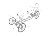
도 1은 본 발명의 제 1 실시예에 따른 멀티트랙 차량의 사시도이다.
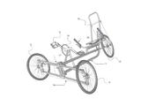
도 2는 본 발명의 제 1 실시예에 따른 멀티트랙 차량의 측면도이다.
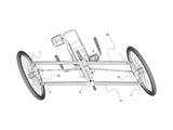
도 3은 본 발명의 제 1 실시예에 따른 멀티트랙 차량의 틸팅 동작을 보여주는 사시도이다.
도 4a 및 도 4b는 본 발명의 제 1 실시예에 따른 멀티트랙 차량의 조향-틸팅 장치의 구조와 기능을 보여주는 정면도이다.
도 5는 본 발명의 제 1 실시예에 따른 멀티트랙 차량의 2축 회전운동 결합체의 구성을 보여주는 분해도이다.
도 6은 본 발명의 제 1 실시예에 따른 멀티트랙 차량의 또 다른 2축 회전운동 결합체의 구성을 보여주는 분해도이다.
도 7a 내지 도 7d는 본 발명의 제 1 실시예에 따른 자세 안정화 장치의 구조와 기능을 보여주는 분해도이다.
도 8a 및 도 8b는 본 발명의 제 1 실시예에 따른 자세 안정화 장치의 탄성체의 구조별 작동모습을 보여주는 개략도이다.
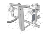
도 9는 본 발명의 제 2 실시예에 따른 멀티트랙 차량의 결합부를 확대한 사시도이다.
도 10은 본 발명의 제 2 실시예에 따른 멀티트랙 차량의 자세 안정화 장치의 사시도이다.
도 11은 본 발명의 제 2 실시예에 따른 멀티트랙 차량이 틸팅할 시 결합부를 확대한 사시도이다.
도 12는 본 발명의 제 2 실시예에 따른 멀티트랙 차량의 선형 액추에이터로 작동하는 자세 안정화 장치의 사시도이다.
도 13a 내지 도 13d는 본 발명의 자세 안정화 장치의 구성과 작동원리를 보여주는 개략도이다.1 is a perspective view of a multi-track vehicle according to a first embodiment of the present invention.
2 is a side view of a multitrack vehicle according to a first embodiment of the present invention.
3 is a perspective view showing a tilting operation of the multi-track vehicle according to the first embodiment of the present invention.
4A and 4B are front views showing the structure and function of the steering-tilting apparatus of the multi-track vehicle according to the first embodiment of the present invention.
5 is an exploded view showing a configuration of a biaxial rotational movement combination body of a multi-track vehicle according to a first embodiment of the present invention.
6 is an exploded view showing a configuration of another biaxial rotational movement combination of a multi-track vehicle according to the first embodiment of the present invention.
7A to 7D are exploded views showing the structure and function of the posture stabilization apparatus according to the first embodiment of the present invention.
8A and 8B are schematic views showing an operation of each structure of an elastic body of the posture stabilization device according to the first embodiment of the present invention.
9 is an enlarged perspective view of a coupling portion of a multitrack vehicle according to a second embodiment of the present invention.
10 is a perspective view of a posture stabilizing apparatus for a multitrack vehicle according to a second embodiment of the present invention.
11 is an enlarged perspective view of a coupling portion when the multi-track vehicle according to the second embodiment of the present invention is tilted.
12 is a perspective view of a posture stabilizing device operating as a linear actuator of a multi-track vehicle according to a second embodiment of the present invention.
13A to 13D are schematic views showing the configuration and operation principle of the posture stabilization device of the present invention.
본 발명은 코너링 시 주행 경로가 그리는 원의 중심으로 차체를 기울여 원심력을 극복하는 틸팅 기능을 갖춘 멀티트랙 차량 및 그를 위한 자세 안정화 장치에 관한 것으로서, 두 종류의 멀티트랙 차량 실시예와 두 종류의 자세 안정화 장치 실시예를 차례대로 제시한다.The present invention relates to a multi-track vehicle having a tilting function for overcoming a centrifugal force by inclining a vehicle body to a center of a circle drawn by a traveling path at the time of cornering, and a posture stabilizing device therefor. The stabilizer embodiments are presented in order.
우선 도 1 내지 도 8b를 참조하여 제 1 실시예를 설명한다.First, the first embodiment will be described with reference to Figs. 1 to 8B.
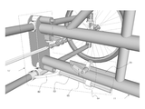
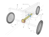
도 1은 본 발명의 제 1 실시예에 따른 멀티트랙 차량의 사시도이다. 상기 멀티트랙 차량은 앞뒤로 배치되어 전체적인 차량 구조를 결정하는 메인프레임(11)과 상기 메인프레임(11)의 비교적 중앙부위에 결합하여 탑승자의 하중을 지지하는 하나 이상의 의자(12)와 상기 의자의 후방에서 상기 메인프레임(11)에 결합하는 하나 이상의 뒷바퀴(13)와 상기 의자의 전방에서 상기 메인프레임(11)에 결합하는 좌우 대칭되는 형상의 조향-틸팅 장치(14)와 상기 조향-틸팅 장치의 좌우측에 각각 결합하는 두 개의 앞바퀴(15, 16)로 이루어진다.1 is a perspective view of a multi-track vehicle according to a first embodiment of the present invention. The multitrack vehicle includes a
도 1에 도시한 멀티트랙 차량은 페달(18)과 크랭크(19)를 구비한 인력운송수단의 일종이나 본 발명은 순수 동력기관의 출력으로만 주행하는 차량에도 적용할 수 있다.The multitrack vehicle shown in FIG. 1 is a type of human-powered vehicle having a
상기 멀티트랙 차량은 도 3에 도시한 바와 같이 코너링 시 차체를 기울여 틸팅 동작을 수행하는데, 여기서 메인프레임(11) 전체가 기울고 조향-틸팅 장치(14) 내부에는 지면과 항상 평행을 유지하는 구성요소들이 존재함을 확인 가능하다.As shown in FIG. 3, the multitrack vehicle performs a tilting operation by tilting the vehicle body at the time of cornering, in which the
도 4a 및 도 4b는 조향-틸팅 장치의 구조와 기능을 보여준다.4A and 4B show the structure and function of the steering-tilting apparatus.
도 4a를 참조하면, 상기 조향-틸팅 장치는 좌우로 소정의 길이를 갖고 각 중앙 부위가 메인프레임에 앞뒤방향의 중심선을 갖는 피봇으로 연결된 로어암(41)과 어퍼암(42) 그리고 상기 로어암과 상기 어퍼암의 좌우측 각각 양쪽 끝단에 앞뒤방향의 중심선을 갖는 피봇으로 연결된 2축 회전운동 결합체(43, 44)로 이루어진다.Referring to FIG. 4A, the steering-tilting apparatus includes a
여기서 상기 조향-틸팅 장치의 중앙 부위의 상하 두 피봇(A, B)과 좌측의 상하 두 피봇(E, F)을 가상으로 연결한 도형은 평행사변형을 이루고 동시에 상기 조향-틸팅 장치의 중앙 부위의 상하 두 피봇(A, B)과 우측의 상하 두 피봇(C, D)을 가상으로 연결한 도형도 평행사변형을 이루며, 도 4b에 도시한 바와 같이 이들 평행상태는 틸팅 시 상기 메인프레임이 기울어지더라도 변함이 없다.In this case, the figure in which the two upper and lower pivots (A, B) of the central portion of the steering-tilting apparatus and the two upper and lower pivots (E, F) on the left are virtually connected form a parallelogram, and at the same time, As shown in FIG. 4B, the parallel state is a state in which the main frame is inclined when the tilting is performed, and when the tilting is performed, There is no change.
상기 2축 회전운동 결합체의 상세한 구성은 도 5의 분해도에 도시하였다. 2축 회전운동 결합체(44)는 아래위방향의 회전중심선을 갖는 조향너클(45)과 상기 조향너클에 고정되어 상기 앞바퀴(16)와 결합하는 앞바퀴축(46)을 포함한다.The detailed configuration of the biaxial rotational movement assembly is shown in the exploded view of Fig. The biaxial
여기서 상기 조향너클을 로어암(41)과 어퍼암(42)에 연결하기 위한 기계요소로서 두 개의 베어링(51, 52)과 두 개의 앵클(47, 48)을 사용하였는데, 이는 도 6에 도시한 바와 같이 로드 엔드 베어링(47a, 48a)으로 대체하면 구성이 단순해져 생산과 정비유지가 용이해진다.Two
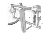
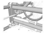
도 7a 내지 도 7d에는 본 발명의 제 1 실시예에 따른 자세 안정화 장치의 구조와 기능을 도시하였다.7A to 7D illustrate the structure and function of the posture stabilization apparatus according to the first embodiment of the present invention.
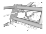
상기 자세 안정화 장치는, 상기 메인프레임과 상기 조향-틸팅 장치 사이에 기계적인 연결이 이루어지는 부위인 결합부(17)에 위치한다. 도 7a를 참조하면, 상기 자세 안정화 장치는 멀티트랙 차량이 틸팅할 때 상기 메인프레임과 상기 조향-틸팅 장치 사이의 상대운동에 의해 자세복원력을 생성하는 균형보조 장치(61)와 생성되는 자세복원력의 크기를 조정하는 조정수단(64)으로 구성된다.The posture stabilization device is located at the
상기 균형보조 장치는 아래위로 소정의 길이를 갖는 탄성체(63)와 상기 탄성체의 한쪽 끝을 상기 로어암의 중앙에 고정하는 고정수단(62)으로 이루어지되, 도 7b를 함께 참고하면, 상기 탄성체(63)의 고정되지 않은 다른 끝은 틸팅 시 상기 메인프레임을 따라 좌우로 기울어지면서 굽힘이 일어나고 그 반작용으로 발생하는 토크가 상기 메인프레임을 원위치로 되돌리려는 복원력으로 작용하게 된다.The balance assisting device comprises an
그리고 도 7c를 참조하면, 상기 조정수단(64)은 상기 탄성체(63)를 따라 아래위로 이동하되 해당 위치에서 상기 탄성체를 상기 메인프레임에 고정함으로써 탄성체의 전체 길이에서 굽힘이 일어나는 부분의 길이(H)를 결정하게 된다.7C, the adjusting means 64 moves up and down along the
상기 조정수단(64)은 탄성체의 길이 범위 내에서 임의의 모든 위치를 가질 수 있으므로 상기 자세 안정화 장치는 자세복원력의 크기를 건너뜀 없이 연속적으로 조정 가능하다.Since the adjusting means 64 can have any arbitrary position within the length of the elastic body, the posture stabilizing device can continuously adjust the magnitude of the posture restoring force without skipping.
상술한 내용에서 고정수단이 로어암에 결합한 모습을 도시하였으나, 상기 자세 안정화 장치를 거꾸로 뒤집어 고정수단을 어퍼암에 결합한 구조도 물론 가능하다.In the above description, the fixing means is coupled to the lower arm, but it is of course possible that the posture stabilizing device is turned upside down and the fixing means is coupled to the upper arm.
그림에서 상기 조정수단(64)은 잠금수단(65)을 포함하여 탑승자가 수동으로 상기 조정수단을 이동시킨 후 상기 잠금수단으로 위치를 고정함을 알 수 있다.In the figure, it can be seen that the adjusting means 64 includes a locking means 65 to allow the passenger to manually move the adjusting means and fix the position with the locking means.
자세복원력을 조절하는 데 있어 탑승자에게 편의를 제공하기 위해 상기 멀티트랙 차량은 그 조종장치에 상기 조정수단(64)의 위치를 원격으로 변경할 수 있는 조정시스템을 추가로 구비하면 좋을 것이다.In order to provide comfort to the passenger in adjusting the posture restoring force, the multitrack vehicle may further include an adjustment system that can remotely change the position of the adjusting means 64 in the steering device.
우선 상기 조정시스템은 멀티트랙 차량의 조종장치에 구비되어 탑승자가 조작하는 조작수단과 상기 조작수단과 상기 조정수단을 상호 연결하는 하나 이상의 케이블로 이루어질 수 있는데, 이 방식은 자전거산업 영역에서 무수한 공지발명들이 존재하는 브레이크 또는 변속기 작동 방식과 다르지 않으므로 별도의 도면은 생략한다.First, the adjustment system may be composed of one or more cables that are provided in the steering apparatus of the multi-track vehicle and connect the operating means operated by the occupant and the operating means and the adjusting means. Are not different from those of the existing brakes or transmissions, so that separate drawings are omitted.
또 다른 조정시스템은 도 7d에 도시한 바와 같이 멀티트랙 차량의 조종장치에 구비되어 탑승자가 조작하는 조작수단과 상기 조작수단의 통제 신호에 따라 상기 조정수단을 전기동력으로 이동시키는 선형 액추에이터로 이루어질 수도 있다.Another adjustment system may include an operating means provided in the steering apparatus of the multitrack vehicle for operating the occupant and a linear actuator for moving the adjusting means in an electric power in accordance with a control signal of the operating means, have.
제 1 실시예에서 상기 탄성체(63)는 여러 개의 판스프링을 좌우로 겹친 구조로 이루어졌는데, 판스프링을 겹칠 때는 도 8a에 도시한 바와 같이 상기 탄성체의 길이방향 중심선을 기준으로 거리가 멀수록 길이가 증가하도록 배치하거나 그와 반대로 도 8b에 도시한 바와 같이 중심선에서 거리가 멀수록 판스프링의 길이가 감소하도록 배치할 수도 있다.In the first embodiment, the
이어서 도 9 내지 도 12를 참조하여 제 2 실시예를 설명한다.Next, a second embodiment will be described with reference to Figs. 9 to 12. Fig.
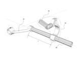
본 발명이 제시하는 제 2 실시예는 탄성체의 비틀림을 이용하여 자세복원력을 제공하는 멀티트랙 차량에 관한 것으로서, 차량의 기본 구조는 제 1 실시예와 동일하므로 서로 차이가 분명한 자세 안정화 장치의 구조와 작동원리에 국한해 설명하기로 한다.The second embodiment of the present invention relates to a multitrack vehicle that provides a posture restoring force by using a twist of an elastic body. Since the basic structure of the vehicle is the same as that of the first embodiment, the structure of the posture stabilizer The operation principle will be described below.
도 9는 본 발명의 제 2 실시예에 따른 멀티트랙 차량의 결합부를 확대한 사시도이다.9 is an enlarged perspective view of a coupling portion of a multitrack vehicle according to a second embodiment of the present invention.
여기에서 자세 안정화 장치는, 앞뒤로 소정의 길이를 갖는 탄성체(63)와 상기 탄성체의 한쪽 끝을 로어암의 중앙에 고정하는 고정수단(62)과 상기 탄성체(63)를 따라 앞뒤로 이동하되 해당 위치에서 상기 탄성체를 메인프레임(11)에 고정하는 조정수단(64)으로 이루어짐을 확인할 수 있다.The posture stabilizing device includes an
상기 멀티트랙 차량이 틸팅할 때 상기 메인프레임과 로어암 사이에 발생하는 상대운동은 상기 탄성체(63)에 비틀림을 발생시키는데, 구체적으로 설명하자면 상기 로어암은 차체의 기울기와 무관하게 항상 지면과 평행하므로 그것과 고정수단(62)으로 연결된 탄성체(63)의 앞부분은 틸팅 시 회전하지 않는 반면, 후방으로 이격되어 상기 조정수단(64)을 통해 상기 메인프레임(11)에 고정된 뒷부분은 차체가 기우는 만큼 회전하게 됨으로써 두 부위 사이엔 비틀림이 발생하는 것이다.When the multi-track vehicle is tilted, the relative motion generated between the main frame and the lower arm causes twisting in the
틸팅 시 상기 탄성체(63)에 비틀림이 발생한 모습은 도 11에 도시하였다. 이 비틀림에 대한 반작용으로 발생하는 토크는 상기 메인프레임(11)을 원위치로 되돌려 세우려는 복원력으로 작용하게 된다.The state in which the
그리고 도 10을 참조하면, 상기 조정수단(64)은 탄성체의 전체 길이에서 굽힘이 일어나는 부분의 길이(L)를 결정한다. 상기 조정수단(64)은 탄성체의 길이 범위 내에서 임의의 모든 위치를 가질 수 있으므로 상기 자세 안정화 장치는 자세복원력의 크기를 건너뜀 없이 연속적으로 조정 가능하다.Referring to FIG. 10, the adjusting means 64 determines the length L of the portion where the bending occurs in the entire length of the elastic body. Since the adjusting means 64 can have any arbitrary position within the length of the elastic body, the posture stabilizing device can continuously adjust the magnitude of the posture restoring force without skipping.
상기 탄성체는 비틀림에 대한 반발력을 제공하는 직선형의 토션바임이 바람직하다.The elastic body is preferably a linear torsion bar providing a repulsive force against twisting.
상술한 내용에서 고정수단이 로어암에 결합한 모습을 도시하였으나, 상기 자세 안정화 장치의 위치를 올려 고정수단을 어퍼암에 결합한 구조도 물론 가능하다.In the above description, the fixing means is coupled to the lower arm. However, it is of course possible to raise the position of the posture stabilization device and connect the fixing means to the upper arm.
조정수단의 위치 변경과 고정을 통한 자세복원력의 조절 방식에 관하여는 제 1 실시예의 설명과 중복되므로 생략한다. 단, 도 12에는 제 2 실시예에 따른 멀티트랙 차량의 자세 안정화 장치를 선형 액추에이터로 작동시키는 모습을 도시하였다.The manner of adjusting the posture restoring force by changing the position of the adjusting means and fixing the position of the adjusting means is the same as that of the first embodiment, and will not be described here. 12 shows a state in which the posture stabilization device of the multitrack vehicle according to the second embodiment is operated by a linear actuator.
도 13a 내지 도 13d에 도시한 본 발명의 제 3 실시예와 제 4 실시예는 자세 안정화 장치 자체에 대한 것으로서, 본 발명의 자세 안정화 장치는 상술한 구조의 멀티트랙 차량 이외에도 다양한 차량에 적용될 수 있으므로 추가적으로 설명한다.The third and fourth embodiments of the present invention shown in Figs. 13A to 13D relate to the posture stabilization device itself, and the posture stabilization device of the present invention can be applied to various vehicles other than the multi-track vehicle having the structure described above Further explanation will be given.
먼저 도 13a 및 도 13b를 참조하여 제 3 실시예의 자세 안정화 장치를 설명한다.First, the posture stabilizing device of the third embodiment will be described with reference to Figs. 13A and 13B.
본 발명에 의한 자세 안정화 장치는 코너링 시 주행 경로가 그리는 원의 중심으로 차체를 기울여 원심력을 극복하는 기능을 갖춘 3륜 이상 멀티트랙 차량의 주행안정성을 향상시키는 장치로서, 상기 멀티트랙 차량은 앞뒤로 소정 길이를 갖는 메인프레임부(91)와 상기 메인프레임부의 후방에 결합하는 하나 이상의 뒷바퀴(13)와 상기 메인프레임부의 전방에 좌우 대칭되는 형상으로 결합하는 조향-틸팅 장치부(92)와 상기 조향-틸팅 장치부의 좌우측 끝에 각각 결합하는 두 개의 앞바퀴(15, 16)로 이루어지고 상기 조향-틸팅 장치는 항시 지면과 평행을 이루는 적어도 하나 이상의 수평유지면(94)을 갖추며, 상기 자세 안정화 장치는 상기 수평유지면 중 하나에 회전이 불가하도록 고정된 고정수단(62)과 상기 고정수단에 한쪽 끝이 회전이 불가하도록 고정되고 상기 수평유지면에 대해 수직으로 소정의 길이를 갖는 탄성체(63)와 상기 탄성체를 따라 이동하되 해당 위치에서 상기 탄성체를 상기 메인프레임부(91)에 고정하는 조정수단(64)으로 이루어짐으로써, 틸팅 시 상기 수평유지면에 대한 상기 메인프레임부의 상대적 회전운동에 의해 상기 탄성체에서 굽힘이 일어나고 그 반작용으로 발생하는 토크가 상기 메인프레임부를 원위치로 되돌리려는 자세복원력으로 작용함과 동시에 그 토크의 크기가 조정수단의 위치에 따라 가변적이다.The posture stabilizing apparatus according to the present invention is an apparatus for improving the running stability of a multi-track vehicle having three or more wheels having a function of overcoming a centrifugal force by tilting the vehicle body at the center of a circle drawn by a traveling path at the time of cornering, A steering-tilting device part (92) which is symmetrically mounted on the front of the main frame part, and a steering-tilting device part (91) The steering and tilting apparatus includes at least one horizontal holding surface (94) parallel to the ground at all times, and the posture stabilizing device includes a horizontal A fixing means 62 fixed to one of the holding surfaces so as to be impossible to rotate, and a fixing means 62 fixed to the fixing means such that one end thereof can not be rotated And an adjustment means (64) for moving the elastic body (63) along the elastic body and fixing the elastic body to the main frame portion (91) at the position, the tilting The bending occurs in the elastic body due to the relative rotation of the main frame portion with respect to the horizontal holding surface and the torque generated by the reaction acts as a posture restoring force to return the main frame portion to its original position, It is variable depending on the location of the means.
여기서 상기 탄성체는 여러 개의 판스프링을 겹쳐 이루어진다.Here, the elastic body is formed by overlapping a plurality of leaf springs.
끝으로 도 13c 및 도 13d를 참조하여 제 4 실시예의 자세 안정화 장치를 설명한다.Finally, the posture stabilizing device of the fourth embodiment will be described with reference to Figs. 13C and 13D.
본 발명에 의한 자세 안정화 장치는 코너링 시 주행 경로가 그리는 원의 중심으로 차체를 기울여 원심력을 극복하는 기능을 갖춘 3륜 이상 멀티트랙 차량의 주행안정성을 향상시키는 장치로서, 상기 멀티트랙 차량은 앞뒤로 소정 길이를 갖는 메인프레임부(91)와 상기 메인프레임부의 후방에 결합하는 하나 이상의 뒷바퀴(13)와 상기 메인프레임부의 전방에 좌우 대칭되는 형상으로 결합하는 조향-틸팅 장치부(92)와 상기 조향-틸팅 장치부의 좌우측 끝에 각각 결합하는 두 개의 앞바퀴(15, 16)로 이루어지고 상기 조향-틸팅 장치는 항시 지면과 평행을 이루는 적어도 하나 이상의 수평유지면(94)을 갖추며, 상기 자세 안정화 장치는 상기 수평유지면 중 하나에 회전이 불가하도록 고정된 고정수단(62)과 상기 고정수단에 한쪽 끝이 회전이 불가하도록 고정되고 상기 수평유지면에 대해 평행으로 소정의 길이를 갖는 탄성체(63)와 상기 탄성체를 따라 이동하되 해당 위치에서 상기 탄성체를 상기 메인프레임부(91)에 고정하는 조정수단(64)으로 이루어짐으로써, 틸팅 시 상기 수평유지면에 대한 상기 메인프레임부의 상대적 회전운동에 의해 상기 탄성체에서 비틀림이 일어나고 그 반작용으로 발생하는 토크가 상기 메인프레임부를 원위치로 되돌리려는 자세복원력으로 작용함과 동시에 그 토크의 크기가 조정수단의 위치에 따라 가변적이다.The posture stabilizing apparatus according to the present invention is an apparatus for improving the running stability of a multi-track vehicle having three or more wheels having a function of overcoming a centrifugal force by tilting the vehicle body at the center of a circle drawn by a traveling path at the time of cornering, A steering-tilting device part (92) which is symmetrically mounted on the front of the main frame part, and a steering-tilting device part (91) The steering and tilting apparatus includes at least one horizontal holding surface (94) parallel to the ground at all times, and the posture stabilizing device includes a horizontal A fixing means 62 fixed to one of the holding surfaces so as to be impossible to rotate, and a fixing means 62 fixed to the fixing means such that one end thereof can not be rotated And an adjustment means (64) for moving the elastic body (63) along the elastic body and fixing the elastic body to the main frame portion (91) at the corresponding position, The torque generated by the reaction occurs in the elastic body due to the relative rotational movement of the main frame portion relative to the horizontal holding surface, acts as a posture restoring force to return the main frame portion to its original position, It is variable depending on the location of the means.
여기서 상기 탄성체는 비틀림에 대한 반발력을 제공하는 직선형의 토션바임이 바람직하다.
Here, the elastic body is preferably a linear torsion bar providing a repulsive force against twisting.
11: 메인프레임 12: 의자
13: 뒷바퀴 14: 조향-틸팅 장치
15, 16: 앞바퀴 17: 결합부
18: 페달 19: 크랭크
30: 조종장치 41: 로어암
42: 어퍼암 43, 44: 2축 회전운동 결합체
45: 조향너클 46: 앞바퀴축
47a, 47b: 로드 엔드 베어링 61: 균형보조 장치
62: 고정수단 63: 탄성체
64: 조정수단 65: 잠금수단
66: 선형 액추에이터 64a, 64b, 64c: 조정수단 접촉 위치
91: 메인프레임부 92: 조향-틸팅 장치부11: Mainframe 12: Chair
13: Rear wheel 14: Steering-tilting device
15, 16: front wheel 17:
18: pedal 19: crank
30: Steering device 41: Lower arm
42:
45: Steering knuckle 46: Front wheel shaft
47a, 47b: rod end bearing 61: balance assisting device
62: fixing means 63: elastic body
64: adjusting means 65: locking means
66:
91: Main frame part 92: Steer-tilting device part
Claims (22)
상기 멀티트랙 차량은
앞뒤로 배치되어 전체적인 차량 구조를 결정하는 메인프레임과;
상기 메인프레임의 비교적 중앙부위에 결합하여 탑승자의 하중을 지지하는 하나 이상의 의자와;
상기 의자의 후방에서 상기 메인프레임에 결합하는 하나 이상의 뒷바퀴와;
상기 의자의 전방에서 상기 메인프레임에 결합하는 좌우 대칭되는 형상의 조향-틸팅 장치와;
상기 조향-틸팅 장치의 좌우측에 각각 결합하는 두 개의 앞바퀴로 이루어지고,
상기 메인프레임과 상기 조향-틸팅 장치의 결합부에는 자세 안정화 장치를 구비하되,
상기 자세 안정화 장치는
틸팅 시 상기 메인프레임과 상기 조향-틸팅 장치 사이의 상대운동에 의해 자세복원력을 생성하는 균형보조 장치와;
생성되는 자세복원력의 크기를 조정하는 조정수단을 포함하여 이루어짐을 특징으로 하는 멀티트랙 차량.
In a multi-track vehicle having a tilting function for overcoming centrifugal force by tilting a vehicle body at the center of a circle drawn by a traveling path at the time of cornering,
The multitrack vehicle
A main frame arranged forward and backward to determine the overall vehicle structure;
At least one chair coupled to a relatively central portion of the main frame to support a load of the occupant;
At least one rear wheel coupled to the main frame at the rear of the chair;
A steering-tilting device of a symmetrical shape that is coupled to the main frame in front of the chair;
And two front wheels coupled to left and right sides of the steering-tilting device,
Wherein the main frame and the steering-tilting device are provided with a posture stabilizer at an engagement portion,
The posture stabilization device
A balance assisting device for generating a posture restoring force by relative movement between the main frame and the steering-tilting device when the vehicle is tilted;
And adjusting means for adjusting the magnitude of the generated posture restoring force.
상기 자세 안정화 장치는 자세복원력의 크기를 건너뜀 없이 연속적으로 조정 가능함을 특징으로 하는 멀티트랙 차량.
The method according to claim 1,
Wherein the posture stabilizing device is capable of continuously adjusting the size of the posture restoring force without skipping.
상기 조향-틸팅 장치는
좌우로 소정의 길이를 갖고 하나는 아래에 나머지 하나는 그보다 소정 높이만큼 위에 배치되며 각각의 중앙 부위가 상기 메인프레임에 앞뒤방향의 중심선을 갖는 피봇으로 연결된 로어암과 어퍼암;
상기 로어암과 상기 어퍼암의 좌우측 각각 양쪽 끝단에 앞뒤방향의 중심선을 갖는 피봇으로 연결된 2축 회전운동 결합체로 이루어지되,
상기 조향-틸팅 장치의 중앙 부위의 상하 두 피봇과 좌측 또는 우측의 상하 두 피봇을 가상으로 연결한 도형은 평행사변형을 이루고, 이 평행상태는 틸팅 시 상기 메인프레임이 기울어지더라도 변함없음을 특징으로 하는 멀티트랙 차량.
The method according to claim 1,
The steering-tilting device
A lower arm and an upper arm which are connected to each other by a pivot having a predetermined length in the left and right direction, one in the lower side and the other one in a predetermined height,
Wherein the lower arm and the upper arm are connected to each other by pivotal joints having a center line in the fore-and-aft direction at both ends of the lower arm and the upper arm,
Wherein a figure virtually connecting the upper and lower pivots of the central portion of the steering-tilting apparatus and the upper and lower pivots of the left or right side is a parallelogram, and the parallel state is not changed even when the main frame is tilted at the time of tilting. Multitrack vehicles.
상기 2축 회전운동 결합체를 상기 로어암이나 어퍼암과 연결하는 기계요소는 로드 엔드 베어링일 수도 있음을 특징으로 하는 멀티트랙 차량.
The method of claim 3,
Wherein the mechanical element connecting the biaxial rotary coupling unit to the lower arm or the upper arm may be a rod end bearing.
상기 2축 회전운동 결합체는
아래위방향의 회전중심선을 갖는 조향너클과;
상기 조향너클에 고정되어 상기 앞바퀴와 결합하는 앞바퀴축을 포함함을 특징으로 하는 멀티트랙 차량.
The method of claim 3,
The biaxial rotational movement combination body
A steering knuckle having a downward rotation center line;
And a front wheel shaft fixed to the steering knuckle and engaged with the front wheel.
상기 균형보조 장치는
아래위로 소정의 길이를 갖는 탄성체와;
상기 탄성체의 한쪽 끝을 상기 로어암 또는 상기 어퍼암의 중앙에 고정하는 고정수단으로 이루어지되,
상기 탄성체의 고정되지 않은 다른 끝은 틸팅 시 상기 메인프레임을 따라 좌우로 기울어지면서 굽힘이 일어나고 그 반작용으로 발생하는 토크가 상기 메인프레임을 원위치로 되돌리려는 복원력으로 작용함을 특징으로 하는 멀티트랙 차량.
4. The method according to claim 1 or 3,
The balance assisting device
An elastic body having a predetermined length downward;
And fixing means for fixing one end of the elastic body to the center of the lower arm or the upper arm,
Wherein the other unfixed end of the elastic body tilts left and right along the main frame at the time of tilting to bend, and a torque generated by the reaction acts as a restoring force to return the main frame to its original position.
상기 탄성체는 여러 개의 판스프링을 좌우로 겹친 구조로 이루어짐을 특징으로 하는 멀티트랙 차량.
The method according to claim 6,
Wherein the elastic body has a structure in which a plurality of leaf springs are stacked laterally.
상기 판스프링은 상기 탄성체의 길이방향 중심선을 기준으로 거리가 멀수록 길이가 증가함을 특징으로 하는 멀티트랙 차량.
8. The method of claim 7,
Wherein the leaf spring increases in length as the distance from the longitudinal center line of the elastic body increases.
상기 판스프링은 상기 탄성체의 길이방향 중심선을 기준으로 거리가 멀수록 길이가 감소함을 특징으로 하는 멀티트랙 차량.
8. The method of claim 7,
Wherein the leaf spring decreases in length as the distance from the longitudinal center line of the elastic body increases.
상기 조정수단은 상기 탄성체를 따라 아래위로 이동하되 해당 위치에서 상기 탄성체를 상기 메인프레임에 고정함으로써 상기 탄성체의 전체 길이에서 굽힘이 일어나는 부분의 길이를 결정함을 특징으로 하는 멀티트랙 차량.
7. The method of claim 1 or 6,
Wherein the adjusting means determines the length of the portion where bending occurs in the entire length of the elastic body by moving the elastic body up and down along the elastic body and fixing the elastic body to the main frame at the corresponding position.
상기 균형보조 장치는
앞뒤로 소정의 길이를 갖는 탄성체와;
상기 탄성체의 한쪽 끝을 상기 로어암 또는 상기 어퍼암의 중앙에 고정하는 고정수단으로 이루어지되,
상기 탄성체의 고정되지 않은 다른 끝은 틸팅 시 상기 메인프레임을 따라 회전하면서 비틀림이 일어나고 그 반작용으로 발생하는 토크가 상기 메인프레임을 원위치로 되돌리려는 복원력으로 작용함을 특징으로 하는 멀티트랙 차량.
4. The method according to claim 1 or 3,
The balance assisting device
An elastic body having a predetermined length forward and backward;
And fixing means for fixing one end of the elastic body to the center of the lower arm or the upper arm,
Wherein the other end of the elastic body is twisted while rotating along the main frame at the time of tilting, and a torque generated by the reaction acts as a restoring force to return the main frame to its original position.
상기 탄성체는 비틀림에 대한 반발력을 제공하는 직선형의 토션바임을 특징으로 하는 멀티트랙 차량.
12. The method of claim 11,
Wherein said elastic body is a straight torsion bar providing repulsion against torsion.
상기 조정수단은 상기 탄성체를 따라 앞뒤로 이동하되 해당 위치에서 상기 탄성체를 상기 메인프레임에 고정함으로써 상기 탄성체의 전체 길이에서 비틀림이 일어나는 부분의 길이를 결정함을 특징으로 하는 멀티트랙 차량.
The method according to claim 1 or 11,
Wherein the adjusting means moves back and forth along the elastic body, and fixes the elastic body to the main frame at the corresponding position, thereby determining the length of the portion where the elastic body is twisted in the entire length.
상기 조정수단은 잠금수단을 포함하여 탑승자가 수동으로 상기 조정수단을 이동시킨 후 상기 잠금수단으로 위치를 고정함을 특징으로 하는 멀티트랙 차량.
14. The method according to claim 10 or 13,
Wherein the adjusting means includes a locking means to manually position the locking means after the adjusting means have been moved by the occupant.
상기 멀티트랙 차량은 그 조종장치에 상기 조정수단의 위치를 원격으로 변경할 수 있는 조정시스템을 추가로 구비함을 특징으로 하는 멀티트랙 차량.
14. The method according to claim 10 or 13,
Wherein the multitrack vehicle further comprises an adjustment system that can remotely change the position of the adjustment means in the steering apparatus.
상기 조정시스템은
상기 조종장치에 구비되어 탑승자가 조작하는 조작수단과;
상기 조작수단과 상기 조정수단을 상호 연결하는 하나 이상의 케이블로 이루어짐을 특징으로 하는 멀티트랙 차량.
16. The method of claim 15,
The adjustment system
An operating means provided in the steering apparatus and operated by an occupant;
And at least one cable interconnecting the operating means and the adjusting means.
상기 조정시스템은
상기 조종장치에 구비되어 탑승자가 조작하는 조작수단과;
상기 조작수단의 통제 신호에 따라 상기 조정수단을 전기동력으로 이동시키는 선형 액추에이터로 이루어짐을 특징으로 하는 멀티트랙 차량.
16. The method of claim 15,
The adjustment system
An operating means provided in the steering apparatus and operated by an occupant;
And a linear actuator for moving the adjusting means by electric power in accordance with a control signal of the operating means.
상기 멀티트랙 차량은 페달과 크랭크를 구비한 인력운송수단임을 특징으로 하는 멀티트랙 차량.
The method according to claim 1,
Wherein the multitrack vehicle is a human-powered vehicle having a pedal and a crank.
상기 멀티트랙 차량은
앞뒤로 소정 길이를 갖는 메인프레임부와;
상기 메인프레임부의 후방에 결합하는 하나 이상의 뒷바퀴와;
상기 메인프레임부의 전방에 좌우 대칭되는 형상으로 결합하는 조향-틸팅 장치부와;
상기 조향-틸팅 장치부의 좌우측 끝에 각각 결합하는 두 개의 앞바퀴로 이루어지고,
상기 조향-틸팅 장치부는 항시 지면과 평행을 이루는 적어도 하나 이상의 수평유지면을 갖추며,
상기 자세 안정화 장치는
상기 수평유지면 중 하나에 회전이 불가하도록 고정된 고정수단과;
상기 고정수단에 한쪽 끝이 회전이 불가하도록 고정되고 상기 수평유지면에 대해 수직으로 소정의 길이를 갖는 탄성체와;
상기 탄성체를 따라 이동하되 해당 위치에서 상기 탄성체를 상기 메인프레임부에 고정하는 조정수단으로 이루어짐으로써,
틸팅 시 상기 수평유지면에 대한 상기 메인프레임부의 상대적 회전운동에 의해 상기 탄성체에서 굽힘이 일어나고 그 반작용으로 발생하는 토크가 상기 메인프레임부를 원위치로 되돌리려는 자세복원력으로 작용함과 동시에 그 토크의 크기가 조정수단의 위치에 따라 가변적인 특징을 갖는 자세 안정화 장치.
A posture stabilization device for improving the running stability of a multi-track vehicle having three or more wheels having a function of overcoming a centrifugal force by inclining a vehicle body to a center of a circle drawn by a traveling path at the time of cornering,
The multitrack vehicle
A main frame part having a predetermined length in the front and back;
At least one rear wheel coupled to the rear of the main frame portion;
A steering-tilting device unit which is coupled to the front of the main frame part in a symmetrical shape;
And two front wheels coupled to left and right ends of the steering-tilting device,
Wherein the steering-tilting device includes at least one horizontal holding surface that is always parallel to the ground,
The posture stabilization device
Fixing means fixed to one of the horizontal holding surfaces so as to be impossible to rotate;
An elastic body fixed to the fixing means so that one end thereof can not be rotated and has a predetermined length perpendicular to the horizontal holding surface;
And adjusting means for moving the elastic body along the elastic body and fixing the elastic body to the main frame portion at the corresponding position,
The bending occurs in the elastic body due to the relative rotational movement of the main frame portion relative to the horizontal holding surface at the time of tilting and the torque generated by the reaction acts as a posture restoring force for returning the main frame portion to its original position, The position stabilizing device having a characteristic that varies depending on the position of the adjusting means.
상기 탄성체는 여러 개의 판스프링을 겹쳐 이루어짐을 특징으로 하는 자세 안정화 장치.
20. The method of claim 19,
Wherein the elastic body is formed by stacking a plurality of leaf springs.
상기 멀티트랙 차량은
앞뒤로 소정 길이를 갖는 메인프레임부와;
상기 메인프레임부의 후방에 결합하는 하나 이상의 뒷바퀴와;
상기 메인프레임부의 전방에 좌우 대칭되는 형상으로 결합하는 조향-틸팅 장치부와;
상기 조향-틸팅 장치부의 좌우측 끝에 각각 결합하는 두 개의 앞바퀴로 이루어지고,
상기 조향-틸팅 장치부는 항시 지면과 평행을 이루는 적어도 하나 이상의 수평유지면을 갖추며,
상기 자세 안정화 장치는
상기 수평유지면 중 하나에 회전이 불가하도록 고정된 고정수단과;
상기 고정수단에 한쪽 끝이 회전이 불가하도록 고정되고 상기 수평유지면에 대해 평행으로 소정의 길이를 갖는 탄성체와;
상기 탄성체를 따라 이동하되 해당 위치에서 상기 탄성체를 상기 메인프레임부에 고정하는 조정수단으로 이루어짐으로써,
틸팅 시 상기 수평유지면에 대한 상기 메인프레임부의 상대적 회전운동에 의해 상기 탄성체에서 비틀림이 일어나고 그 반작용으로 발생하는 토크가 상기 메인프레임부를 원위치로 되돌리려는 자세복원력으로 작용함과 동시에 그 토크의 크기가 조정수단의 위치에 따라 가변적인 특징을 갖는 자세 안정화 장치.
A posture stabilization device for improving the running stability of a multi-track vehicle having three or more wheels having a function of overcoming a centrifugal force by inclining a vehicle body to a center of a circle drawn by a traveling path at the time of cornering,
The multitrack vehicle
A main frame part having a predetermined length in the front and back;
At least one rear wheel coupled to the rear of the main frame portion;
A steering-tilting device unit which is coupled to the front of the main frame part in a symmetrical shape;
And two front wheels coupled to left and right ends of the steering-tilting device,
Wherein the steering-tilting device includes at least one horizontal holding surface that is always parallel to the ground,
The posture stabilization device
Fixing means fixed to one of the horizontal holding surfaces so as to be impossible to rotate;
An elastic body fixed to the fixing means such that one end thereof is not rotatable and has a predetermined length parallel to the horizontal holding surface;
And adjusting means for moving the elastic body along the elastic body and fixing the elastic body to the main frame portion at the corresponding position,
The torsion occurs in the elastic body due to the relative rotational movement of the main frame portion relative to the horizontal holding surface at the time of tilting and the torque generated by the reaction acts as a posture restoring force to return the main frame portion to its original position, The position stabilizing device having a characteristic that varies depending on the position of the adjusting means.
상기 탄성체는 토션바임을 특징으로 하는 자세 안정화 장치.
22. The method of claim 21,
Wherein the elastic body is a torsion bar.
Priority Applications (1)
| Application Number | Priority Date | Filing Date | Title |
|---|---|---|---|
| KR20120141526A KR101487582B1 (en) | 2012-12-06 | 2012-12-06 | Multi-track vehicle having a tilting mechanism, and stabilizers therefore |
Applications Claiming Priority (1)
| Application Number | Priority Date | Filing Date | Title |
|---|---|---|---|
| KR20120141526A KR101487582B1 (en) | 2012-12-06 | 2012-12-06 | Multi-track vehicle having a tilting mechanism, and stabilizers therefore |
Publications (2)
| Publication Number | Publication Date |
|---|---|
| KR20140073368A true KR20140073368A (en) | 2014-06-16 |
| KR101487582B1 KR101487582B1 (en) | 2015-01-29 |
Family
ID=51126939
Family Applications (1)
| Application Number | Title | Priority Date | Filing Date |
|---|---|---|---|
| KR20120141526A KR101487582B1 (en) | 2012-12-06 | 2012-12-06 | Multi-track vehicle having a tilting mechanism, and stabilizers therefore |
Country Status (1)
| Country | Link |
|---|---|
| KR (1) | KR101487582B1 (en) |
Cited By (2)
| Publication number | Priority date | Publication date | Assignee | Title |
|---|---|---|---|---|
| CN109278918A (en) * | 2018-11-21 | 2019-01-29 | 昆山乐迪高运动用品有限公司 | Electric vehicle and its steering mechanism |
| WO2020091236A1 (en) * | 2018-10-29 | 2020-05-07 | 변규진 | Reverse tricycle comprising three driving parts, and performing tilting function by natural angle simultaneously with steering |
Families Citing this family (1)
| Publication number | Priority date | Publication date | Assignee | Title |
|---|---|---|---|---|
| CN105109598B (en) * | 2015-08-24 | 2018-10-19 | 昆山百瑞康儿童用品有限公司 | A kind of children's electric motor vehicle |
Family Cites Families (3)
| Publication number | Priority date | Publication date | Assignee | Title |
|---|---|---|---|---|
| JP2005199754A (en) * | 2004-01-13 | 2005-07-28 | Masayoshi Nohata | Oscillating mechanism for tricycle |
| JP4804068B2 (en) * | 2005-08-16 | 2011-10-26 | パナソニック株式会社 | Tricycle |
| JP4297967B1 (en) * | 2008-08-11 | 2009-07-15 | 株式会社アズマ技研 | Front motorcycle |
-
2012
- 2012-12-06 KR KR20120141526A patent/KR101487582B1/en active IP Right Grant
Cited By (3)
| Publication number | Priority date | Publication date | Assignee | Title |
|---|---|---|---|---|
| WO2020091236A1 (en) * | 2018-10-29 | 2020-05-07 | 변규진 | Reverse tricycle comprising three driving parts, and performing tilting function by natural angle simultaneously with steering |
| KR20200047973A (en) * | 2018-10-29 | 2020-05-08 | 변규진 | whole body drive -reverse trike |
| CN109278918A (en) * | 2018-11-21 | 2019-01-29 | 昆山乐迪高运动用品有限公司 | Electric vehicle and its steering mechanism |
Also Published As
| Publication number | Publication date |
|---|---|
| KR101487582B1 (en) | 2015-01-29 |
Similar Documents
| Publication | Publication Date | Title |
|---|---|---|
| JP6408168B2 (en) | vehicle | |
| JP5034948B2 (en) | vehicle | |
| EP3066001B1 (en) | Three-wheeled tilting bicycle | |
| EP2905209B1 (en) | Vehicle | |
| JP6153049B1 (en) | Three-wheeled vehicle | |
| JP6380485B2 (en) | Traveling device | |
| EP2703270B1 (en) | Vehicle | |
| CN112867667A (en) | Motor vehicle with two rear wheels | |
| KR101487582B1 (en) | Multi-track vehicle having a tilting mechanism, and stabilizers therefore | |
| US20230257055A1 (en) | Three-Wheeled Vehicle With Multipart Frame | |
| JP2013144513A (en) | Vehicle | |
| JP2011025843A (en) | Vehicle | |
| JP2021176754A (en) | vehicle | |
| JP6903311B2 (en) | Suspension device | |
| JP5458722B2 (en) | vehicle | |
| JP7420699B2 (en) | vehicle | |
| WO2012092182A1 (en) | Motorized cycle | |
| CN109987184B (en) | Scooter | |
| WO2017137923A1 (en) | Dual arm single-shock-absorber assembly for a pair of wheels of a velocipede | |
| NL1035799C2 (en) | Tiltable tricycle, has left outer tubular member and right tubular member respectively and pivotally connected to another left outer tubular member and another right tubular member by hinge | |
| WO2018180754A1 (en) | Vehicle | |
| CN108883808B (en) | Two-wheeled vehicle | |
| EP2692612A1 (en) | Wheeled vehicle | |
| EP4197890A1 (en) | Traveling vehicle | |
| EP3656587B1 (en) | Vehicle |
Legal Events
| Date | Code | Title | Description |
|---|---|---|---|
| A201 | Request for examination | ||
| N231 | Notification of change of applicant | ||
| E902 | Notification of reason for refusal | ||
| E902 | Notification of reason for refusal | ||
| E701 | Decision to grant or registration of patent right | ||
| GRNT | Written decision to grant | ||
| FPAY | Annual fee payment |
Payment date: 20180212 Year of fee payment: 4 |
|
| FPAY | Annual fee payment |
Payment date: 20190122 Year of fee payment: 5 |
|
| FPAY | Annual fee payment |
Payment date: 20191216 Year of fee payment: 6 |