WO2019007259A1 - 一种悬架特性试验车轮六自由度位移测量装置及方法 - Google Patents
一种悬架特性试验车轮六自由度位移测量装置及方法 Download PDFInfo
- Publication number
- WO2019007259A1 WO2019007259A1 PCT/CN2018/093425 CN2018093425W WO2019007259A1 WO 2019007259 A1 WO2019007259 A1 WO 2019007259A1 CN 2018093425 W CN2018093425 W CN 2018093425W WO 2019007259 A1 WO2019007259 A1 WO 2019007259A1
- Authority
- WO
- WIPO (PCT)
- Prior art keywords
- wheel
- binocular vision
- vehicle
- target
- measuring instrument
- Prior art date
- Legal status (The legal status is an assumption and is not a legal conclusion. Google has not performed a legal analysis and makes no representation as to the accuracy of the status listed.)
- Ceased
Links
Images




Classifications
-
- G—PHYSICS
- G01—MEASURING; TESTING
- G01B—MEASURING LENGTH, THICKNESS OR SIMILAR LINEAR DIMENSIONS; MEASURING ANGLES; MEASURING AREAS; MEASURING IRREGULARITIES OF SURFACES OR CONTOURS
- G01B11/00—Measuring arrangements characterised by the use of optical techniques
- G01B11/02—Measuring arrangements characterised by the use of optical techniques for measuring length, width or thickness
- G01B11/03—Measuring arrangements characterised by the use of optical techniques for measuring length, width or thickness by measuring coordinates of points
-
- Y—GENERAL TAGGING OF NEW TECHNOLOGICAL DEVELOPMENTS; GENERAL TAGGING OF CROSS-SECTIONAL TECHNOLOGIES SPANNING OVER SEVERAL SECTIONS OF THE IPC; TECHNICAL SUBJECTS COVERED BY FORMER USPC CROSS-REFERENCE ART COLLECTIONS [XRACs] AND DIGESTS
- Y02—TECHNOLOGIES OR APPLICATIONS FOR MITIGATION OR ADAPTATION AGAINST CLIMATE CHANGE
- Y02T—CLIMATE CHANGE MITIGATION TECHNOLOGIES RELATED TO TRANSPORTATION
- Y02T90/00—Enabling technologies or technologies with a potential or indirect contribution to GHG emissions mitigation
Definitions
- the invention belongs to the technical field of automobile suspension performance testing, and particularly relates to a six-degree-of-freedom displacement measuring device and method for a suspension characteristic test wheel.
- the traditional vehicle suspension characteristic test bench adopts a quasi-static loading method to simulate the force and displacement movement of the vehicle while driving on the road surface.
- the vehicle is fixed on the test bench to load the wheel through the wheel.
- the six-degree-of-freedom displacement measuring device and method measure changes of wheel alignment parameters in a vehicle coordinate system when the wheel is moving or loaded.
- the wheel positioning parameters mainly include: wheel center space coordinates, wheel camber angle ⁇ , wheel rotation angle ⁇ , and wheel steering angle ⁇ .
- the characteristics of the suspension are usually described in the car coordinate system, and the test result is the displacement of the wheel relative to the body.
- the car coordinate system (X V , Y V , Z V ) is a right-handed rectangular coordinate system with the sprung mass center (O V ) as the origin. The coordinate system moves and rotates together with the sprung mass, at rest.
- the X V axis points forward in the horizontal plane, the Y V axis points to the left in the horizontal plane, and the Z V axis points upward;
- the body coordinate system (X, Y, Z) is based on the wheel center (O) of the wheel.
- the X-axis and the Z-axis are in the middle plane of the wheel, the X-axis is horizontally forward, and the Y-axis is the center line of the wheel rotation axis, and the Z-axis is upward.
- the wheel coordinate system (X W , Y W , Z W ) is a right-handed rectangular coordinate system with the wheel center (O W ) as the origin, and the X W axis and the Z W axis are in the middle plane of the wheel.
- the X W axis is horizontally forward, and the Y W axis is the center line of the wheel rotation axis, and the Z W axis is upward.
- the wheel steering angle ⁇ is the angle between the vehicle coordinate system X V axis and the wheel coordinate system X W axis
- the wheel camber angle ⁇ is the angle between the vehicle coordinate system Z V axis and the wheel coordinate system Z W axis
- the wheel rotation angle ⁇ The angle at which the X W axis and the Z W axis are rotated about the wheel rotation axis Y W axis.
- the six-degree-of-freedom displacement measuring device for the suspension characteristic test bench has two main forms.
- One uses a measuring arm to measure the six-degree-of-freedom displacement of the wheel through six rotating shafts and corresponding angle sensors.
- the folding state of the measuring arm is the mechanical zero position, which is the zero position of each joint angle sensor.
- the state in which the joints of the measuring arm are perpendicular to each other is the measuring zero position.
- the six-degree-of-freedom displacement solving formula of the wheel is derived from this position.
- the method needs to identify the relative position of the end axis of the measuring arm and the axis of rotation of the wheel, correct the parameters of the measuring arm solution model to ensure the accuracy of the six-degree-of-freedom displacement of the wheel, and the measuring arm mechanism is connected in series, there is a cumulative error; the measuring arm coordinates are required during the test.
- the coordinate axes of the system are parallel to the coordinate axes of the car coordinate system, and the installation accuracy of the measuring arm is high.
- One end of the measuring device is fixed with the clamp, and the impact, flexibility and gravity of the mechanism will affect the dynamic feedback of the corner of the joint; One end is fixed to the test stand and is inconvenient to move.
- the other type uses a wire-type displacement sensor to measure the displacement of the six-degree-of-freedom of the wheel, mainly including five measuring cables for pulling the rope and fixing the rope.
- the wheel can be rotated relative to the measuring Y-axis, and the photoelectric encoder mounted on the measuring disk measures the wheel.
- the rotation angle is obtained by the rotation angle of the wheel.
- the longitudinal and vertical displacements of the wheel center are measured along the X and Z axes, and the lateral displacement, toe angle and camber angle of the wheel center are measured along the three lines of the Y axis.
- the displacement sensor better solves the problem of insufficient resolution of the early angle sensor, but the measurement accuracy will decrease when the body motion is faster.
- the present invention provides a six-degree-of-freedom displacement measuring device and method for a suspension characteristic test wheel, which makes the measurement of wheel positioning parameters more convenient, flexible and accurate during testing.
- the measuring device comprises a binocular vision measuring instrument, an optical target, a data exchange device, a host computer, a wheel positioning fixture and a reference fixture;
- the binocular vision measuring instrument Including a first binocular vision measuring instrument and a second binocular vision measuring instrument, the vehicle to be tested is fixed on a test rig for mounting on the left and right wheels of the vehicle under test, the reference The fixture is mounted on the vehicle to be tested and fixed to the vehicle to be tested, and the optical target is a plurality of, wherein a part of the optical target is distributed on the measurement plane of the wheel alignment fixture and the reference fixture, and another part of the optical target For distributing on the vehicle body of the vehicle to be tested; the first and second binocular vision measuring instruments are respectively configured to measure spatial coordinate changes of the optical target on the left and right sides of the vehicle body of the vehicle to be tested; The first and second binocular vision measuring instruments are simultaneously connected by the data exchange device, and are used for controlling
- the wheel positioning fixture includes a disc, a nut, and a hexagon socket bolt; the disc has a circumferentially distributed straight slot extending in a radial direction, and a gap exists between the straight slot and the hexagon socket bolt.
- One end of the hexagon socket bolt is used for bolt connection with the wheel of the vehicle to be tested, and the other end passes through a straight slot distributed on the disc.
- the nut is disposed on both sides of the disc by a hexagon socket bolt, and the nut on both sides of the disc The direction of rotation is the same.
- the reference fixture includes a connecting bolt, a T-shaped plate, an L-shaped plate, and a flat plate.
- the T-shaped plates are asymmetric at both ends, and have a long end and a short end.
- the vehicle to be tested includes a frame, and the vehicle to be tested The frame has a longitudinal beam, the longitudinal beam has an upper plane and a side plane, and the two planes whose short ends of the T-shaped plate are perpendicular to each other are respectively used for attaching to the upper plane and the side plane of the frame rail and passing through the bolt and the frame Connected, the long end of the T-shaped plate protrudes out of the vehicle body, and the two ends perpendicular to each other of the L-shaped plate are respectively connected with the long end of the T-shaped plate and the flat plate by bolts.
- three optical targets are evenly distributed circumferentially on the measuring plane of the wheel positioning fixture mounted on the left wheel for evenly distributed on the measuring plane of the wheel positioning fixture mounted on the right wheel.
- Three optical targets having an interval of 120° between each of the optical targets distributed on a measurement plane of the wheel alignment fixture and distributed over each of the optical targets on a measurement plane of the wheel alignment fixture.
- the shape is a circle.
- three optical targets are distributed on the measurement plane of the reference fixture, and the three optical targets are respectively an upper target, an intermediate target, and a right target, which are sequentially distributed in an “L” shape.
- the line connecting the intermediate target and the superscript target is perpendicular to the horizontal plane, and the line connecting the intermediate target and the right target is parallel to the advancing direction of the automobile, and the superscript target, the intermediate target and the right target are circular in shape.
- the first binocular vision measuring instrument is placed on the left side of the vehicle body facing the left side wheel, distributed on the measuring plane of the optical target and the reference fixture on the measuring plane of the wheel positioning fixture of the left side wheel
- the optical target is placed in the field of view of the first binocular vision measuring instrument
- the second binocular vision measuring instrument is placed on the right side of the vehicle body facing the right side wheel, distributed on the measuring plane of the wheel positioning fixture of the right wheel
- the optical target is placed in the field of view of the second binocular vision measuring instrument
- a circular optical target with a constant spacing is continuously distributed from the right side of the left wheel to the body directly above the right wheel, and the body of the left side of the wheel is on the body.
- a portion of the target is distributed within the field of view of the first binocular vision meter, and a portion of the target distributed on the body at one end of the right wheel is within the field of view of the second binocular vision meter.
- the invention also includes a six-degree-of-freedom displacement measuring method for a suspension characteristic test wheel, which comprises a binocular vision measuring instrument, an optical target, a data exchange device, a host computer, a wheel positioning fixture and a reference fixture; the binocular vision measurement
- the apparatus includes a first binocular vision measuring instrument and a second binocular vision measuring instrument, the wheel positioning fixture comprising a disk, the reference fixture comprising a flat plate, the measuring method comprising the steps of:
- E1 Fix the vehicle to be tested on the test rig, install the wheel alignment clamp on the wheel of the vehicle to be tested, make the disc parallel to the intermediate plane of the wheel and coaxial with the wheel, and install the reference fixture on the vehicle to be tested.
- the flat plate is parallel to the longitudinal symmetry plane of the vehicle body of the vehicle under test;
- E2 distributing optical targets from the left side to the right side of the vehicle body of the vehicle to be measured, and measuring the relative positional relationship between the optical targets on the vehicle body;
- the optical target is distributed on the wheel alignment fixture and the reference fixture so that the first binocular vision measuring instrument is facing the left wheel, the second binocular vision measuring instrument is facing the right wheel, and the binocular vision measuring instrument and the wheel are adjusted.
- the distance between the optical targets on the left side of the vehicle body is in the field of view of the first binocular vision measuring instrument, and the optical target on the right side of the vehicle body is located in the field of view of the second binocular vision measuring instrument;
- E4 Connect one end of the data exchange device to the upper computer, the other end to the first and second binocular vision measuring instruments, start the upper computer, and establish the first and second pairs through the relative positional relationship between the optical targets on the vehicle body.
- E5 Select the optical target on the wheel alignment fixture to load the vehicle to be tested, and control the first and second binocular vision measuring instruments to simultaneously measure the spatial coordinate changes of the selected target target, and pass the three optics on the wheel positioning fixture.
- the spatial coordinate change of the target and the distance between the disc measurement plane and the intermediate plane of the wheel are used to solve the spatial angle change of the midplane of the wheel in the vehicle coordinate system and the spatial coordinate change of the wheel center, and the left and right wheels in the vehicle coordinate system are obtained.
- the relative positional relationship between the optical targets on the vehicle body in the above step E2 is established by the following method:
- the optical target is continuously distributed from the left side to the right side of the vehicle body at regular intervals, and the first binocular vision measuring instrument is continuously moved to measure the relative positional relationship between the targets on the vehicle body, wherein the first binocular vision measurement after each step of movement
- the instrument's field of view has a portion of the old optical target remaining in the upper step and a new optical target that has just entered the field of view to ensure a continuous transition of the relative positional relationship.
- step E4 the coordinate conversion relationship between the first and second binocular vision measuring instruments is established in the above step E4, including:
- the number of targets on the right side of the vehicle body is greater than or equal to the unknown number of the conversion matrix T, thereby obtaining a conversion matrix T of the second binocular vision measuring instrument coordinate system relative to the first binocular vision measuring instrument coordinate system.
- the invention also includes a six-degree-of-freedom displacement measuring method for a suspension characteristic test wheel, which comprises a binocular vision measuring instrument, an optical target, a plane fixture; the binocular vision measuring instrument comprises a first binocular vision measuring instrument and a A binocular vision measuring instrument, the measuring method comprising the following steps:
- the plane clamp is installed in front of the front of the vehicle to be tested, continuing from directly above the left wheel to directly above the right wheel, and distributing the optical target on the plane of the fixture fixed to the test bench, the first and the first Two binocular vision measuring instruments are respectively placed on the left and right sides of the vehicle body of the vehicle to be tested, and the coordinate conversion relationship between the first and second binocular vision measuring instruments is established according to the relative positional relationship between the optical targets on the vehicle body.
- the spatial coordinates of the optical target measured in the field of view of the binocular vision measuring instrument are converted to the coordinate system of the first binocular vision measuring instrument;
- F2 establishing a six-degree-of-freedom displacement measurement reference coordinate system parallel to the vehicle coordinate system by spatial coordinates of three optical targets on the reference fixture;
- the invention also includes the following calculation method for the six-degree-of-freedom displacement of the wheel:
- T31 The spatial coordinates of the coordinate points A4, A5, A6 of the optical target on the left wheel alignment fixture disc in the first binocular vision measuring instrument coordinate system are directly measured by the first binocular vision measuring instrument. Indirect measurement of the spatial coordinates of the coordinate points A7, A8, A9 of the optical target on the disc of the right wheel alignment fixture in the coordinate system of the first binocular vision measuring instrument
- the rotation axis vector and the wheel center coordinate of the left and right wheels can be expressed in the first binocular vision measuring instrument coordinate system as:
- l WL is the distance between the measurement plane of the left disc and the intermediate plane of the left wheel
- l WR is the distance between the measurement plane of the right disc and the intermediate plane of the right wheel.
- the rotation axis vector and the wheel center coordinate of the left and right wheels can be transferred from the first binocular vision measuring instrument coordinate system to the vehicle coordinate system, which is expressed as:
- T34 According to the spatial coordinate changes of the left and right wheel hubs in the car coordinate system, the three-degree-of-freedom line displacement of the left and right wheels in the vehicle coordinate system is measured, according to the left and right wheel rotation axes and the wheel positioning fixture.
- the change of the angle between the vector of the superscript target in the vehicle coordinate system and the coordinate axis of the car coordinate system measures the three-degree-of-freedom angular displacement of the left and right wheels in the vehicle coordinate system, and the left and right wheel angular displacements.
- the solution method is the same, which is the change of the toe angle, the camber angle and the rotation angle of the left and right wheels. Taking the left wheel as an example, the wheel toe angle ⁇ is calculated by the wheel axis vector in the vehicle coordinate system. Wheel camber angle ⁇ :
- the present invention is a suspension characteristic test wheel multi-degree of freedom displacement measuring device, wherein the measuring device comprises a binocular vision measuring instrument, an optical target, a data exchange device, a host computer, and a wheel positioning fixture. And a reference fixture; the binocular vision measuring instrument comprises a first binocular vision measuring instrument and a second binocular vision measuring instrument, the vehicle to be tested being fixed on the test bench, the wheel positioning fixture being used for mounting on the vehicle to be tested On the left and right wheels, the reference fixture is mounted on a frame of the vehicle under test, and the optical targets are plural, and a part of the optical targets are distributed in the measurement of the wheel alignment fixture and the reference fixture.
- the first and second binocular vision measuring instruments are respectively used to measure the optical target on the left and right sides of the vehicle body of the vehicle to be tested.
- Space coordinate change the upper computer simultaneously connects the first and second binocular vision measuring instruments through the data exchange device, and is used for controlling the first and second binocular vision measuring instruments to be measured and obtained Measurement data, and multiple degrees of freedom of the wheel displacement data calculated in the coordinate systems of the measuring car.
- the invention further comprises a suspension characteristic test wheel multi-degree of freedom displacement measuring method, which comprises a binocular vision measuring instrument, an optical target, a data exchange device, a host computer, a wheel positioning fixture and a reference fixture;
- the eye vision measuring instrument comprises a first binocular vision measuring instrument and a second binocular vision measuring instrument, the wheel positioning fixture comprising a disk, the reference fixture comprising a flat plate, the measuring method comprising the steps of:
- E1 Fix the vehicle to be tested on the test rig, install the wheel alignment clamp on the wheel of the vehicle to be tested, make the disc parallel to the intermediate plane of the wheel and coaxial with the wheel, and install the reference fixture on the vehicle to be tested.
- the flat plate is parallel to the longitudinal symmetry plane of the vehicle body of the vehicle under test;
- E2 distributing optical targets from the left side to the right side of the vehicle body of the vehicle to be measured, and measuring the relative positional relationship between the optical targets on the vehicle body;
- the optical target is distributed on the wheel alignment fixture and the reference fixture so that the first binocular vision measuring instrument is facing the left wheel, the second binocular vision measuring instrument is facing the right wheel, and the binocular vision measuring instrument and the wheel are adjusted.
- the distance between the optical targets on the left side of the vehicle body is in the field of view of the first binocular vision measuring instrument, and the optical target on the right side of the vehicle body is located in the field of view of the second binocular vision measuring instrument;
- E4 Connect one end of the data exchange device to the upper computer, the other end to the first and second binocular vision measuring instruments, start the upper computer, and establish the first and second pairs through the relative positional relationship between the optical targets on the vehicle body.
- E5 Select the optical target on the wheel alignment fixture to load the vehicle to be tested, and control the first and second binocular vision measuring instruments to simultaneously measure the spatial coordinate changes of the selected target target, and pass the three optics on the wheel positioning fixture.
- the spatial coordinate change of the target and the distance between the disc measurement plane and the intermediate plane of the wheel are used to solve the spatial angle change of the midplane of the wheel in the vehicle coordinate system and/or the spatial coordinate change of the wheel center, and the wheel is free in the car coordinate system. Degree displacement.
- the binocular vision measuring instrument is used to measure the multi-degree of freedom displacement of the wheel in the suspension characteristic test, which makes the arrangement, installation, adjustment and measurement of the measuring device more convenient and quicker;
- Figure 1 is a schematic view of a car coordinate system
- Figure 2 is a schematic view of a wheel coordinate system
- Figure 3 is an overall schematic view of the present invention.
- Figure 4 is a schematic view showing the measurement of the left wheel of the present invention.
- Figure 5 is a schematic view showing the measurement of the right wheel of the present invention.
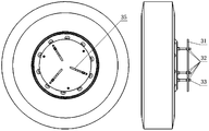
- Figure 6 is a wheel positioning fixture structure of the present invention.
- Figure 7 is a reference jig structure of the present invention.
- Figure 8 is a schematic diagram of the measurement of the present invention.
- Figure 9 is a schematic view of the wheel space angle
- Figure 10 is a schematic illustration of another embodiment of the present invention.
- FIG. 3 is a schematic overall view of a six-degree-of-freedom displacement measuring device and method for a suspension characteristic test wheel according to the present invention, which mainly includes a first binocular vision measuring instrument 41 and a second binocular vision measuring instrument. 42.
- Data exchange device 5 host computer 6, wheel positioning jig 3, and reference jig 2.
- the vehicle 8 to be tested is fixed on the test rig 7, and the wheel alignment jig 3 is mounted on the left and right wheels 81, 82 of the vehicle 8 to be tested, and the reference jig 2 is mounted on the vehicle to be tested.
- the first binocular vision measuring instrument 41 continuously measures the relative positional relationship between the targets on the vehicle body to solve the conversion matrix T between the coordinate systems of the two binocular vision measuring instruments; the two binocular vision measuring instruments 41 and 42 respectively Placed on both sides of the vehicle body of the vehicle under test 8, the spatial coordinate changes of the optical target on the plane of the measuring fixture are unified and unified in the coordinate system of the first binocular vision measuring instrument, and the upper computer 6 is connected to the binocular vision measuring instrument through the data exchange device 5. , controlling its measurement and obtaining measurement data, and calculating the six-degree-of-freedom displacement of the wheel in the vehicle coordinate system based on the measured data.
- FIG. 6 is a structural diagram of a left wheel alignment fixture of a six-degree-of-freedom displacement measuring device for a suspension characteristic test wheel of the present invention, which includes a disk 31, six nuts 32, and three hexagon socket bolts 33.
- One end of the hexagon socket head bolt 33 is connected with the wheel bolt, and the other end passes through the straight slot 35 which is radially distributed on the disc 31.
- the diameter of the hexagon socket bolt is smaller than the slot width of the straight slot 35, and there is a gap between the hexagon socket bolt and the straight slot.
- the adjustment gap is fixed, so that the disc 31 can be moved along the axial direction of the hexagon socket bolt 33 and the radial direction of the disc 31 through the straight slot, and each side of the disc plane has a screw 32 having the same direction and screwed into the hexagon socket bolt.
- the posture of the disc 31 is adjusted so as to be parallel and coaxial with the intermediate plane of the left wheel 81, and the posture of the disc 31 is determined by the two sides of the nuts 32 to be fixed and fixed, and the left and right wheels 81
- the structure and installation requirements of the wheel positioning jig 3 on the 82 are the same.
- the stability of the clamp is ensured by screwing the same nut on each side of the plane to the hexagonal bolt.
- the arrangement of the straight slot makes the wheel alignment clamp easy to install and easy to adjust. It is suitable for all types of wheels. Applicability Strong.
- FIG. 7 is a structural diagram of a reference fixture of a six-degree-of-freedom displacement measuring device for a suspension characteristic test wheel according to the present invention.
- the reference jig can be mounted on either side of the vehicle body, and includes a connecting bolt 21, a T-shaped plate 22, and a L.
- the shape plate 23, the flat plate 24, and the T-shaped plate 22 are asymmetrical at both ends, and the planes perpendicular to the short ends of the T-shaped plate 22 are respectively attached to the upper plane and the side plane of the longitudinal beam of the frame 83, and are connected to the frame 83 through the bolts 21,
- the long ends of the T-shaped plates 22 extend out of the vehicle body, and the two ends perpendicular to each other of the L-shaped plates 23 are respectively connected to the long ends of the T-shaped plates 22 and the flat plate 24 by bolts 21, so that the flat plate plane is parallel to the longitudinal symmetry plane of the automobile, and passes through
- the reference jig is directly mounted on the frame, so that the reference jig has a simple structure, is convenient and stable to install, and has strong applicability.
- FIG. 4 is a left side view showing a six-degree-of-freedom displacement measuring device and method for a suspension characteristic test wheel according to the present invention.
- the reference jig is mounted on the left side of the vehicle body as an example, as shown in FIG. 3-4.
- the forward direction is parallel; the first binocular vision measuring device 41 faces the wheel positioning jig 3 and the reference jig 2, about 2 meters from the measuring plane of the disc 31, and measures the targets 11, 12, 13 on the measuring plane of the fixture in the field of view. , 14, 15, 16 spatial coordinate changes in the coordinate system of the first binocular vision measuring instrument, 5 the amount of data transmitted through the data exchange device 6 to the host computer.
- FIG. 5 is a schematic diagram of the right side of the six-degree-of-freedom displacement measuring device and method for a suspension characteristic test wheel according to the present invention, including a second binocular vision measuring instrument 42, a right side wheel 82, and a wheel positioning fixture. 3. An optical target; wherein, on the measuring plane of the positioning fixture disc 34 fixed to the right wheel 82, three optical targets 17, 18, 19 are evenly distributed along the circumference, and the target is spaced by 120°; the second binocular The vision measuring device 42 faces the wheel positioning fixture disc 34 about 2 meters from its measuring plane, and measures the space of the targets 17, 18, 19 on the measuring plane of the fixture in the field of view of the first binocular vision measuring instrument. The coordinate changes and the measurement data are transmitted to the host computer 6 via the data exchange device 5.
- FIG. 8 is a schematic diagram of a six-degree-of-freedom displacement measurement method for a suspension characteristic test wheel according to the present invention.
- the target coordinate of the second binocular vision measuring instrument in the coordinate system can be obtained by the conversion matrix T. Converting to the coordinate system of the first binocular vision measuring instrument, the optical target 11, 12, 13 on the reference fixture plate 24 and the left wheel alignment fixture disk 31 can be directly measured by the first binocular vision measuring instrument 41.
- the spatial coordinates of coordinates A1, A2, A3, A4, A5, A6 of 14, 15, 16 in the coordinate system of the first binocular vision measuring instrument The spatial coordinates of the coordinate points A7, A8, A9 of the optical targets 17, 18, 19 on the right binocular positioning fixture disk 34 in the coordinate system of the first binocular vision measuring instrument can be indirectly measured.
- the vector of the vehicle coordinate system X V , Y V , Z V axis can be expressed as:
- the vector between the optical targets on the left wheel alignment fixture disc 31 can be expressed as:
- the vector between the optical targets on the right wheel alignment fixture disc 34 can be expressed as:
- the left and right wheel rotation axis vectors can be expressed as:
- l WL is the distance between the measurement plane of the left wheel alignment fixture disc and the intermediate plane of the left wheel
- l WR is the distance between the measurement plane of the right wheel alignment fixture disc and the intermediate plane of the right wheel.
- the vector between the origin O V of the car coordinate system and the left and right wheel centers can be expressed as:
- the coordinates of the left and right wheel center points in the car coordinate system are:
- the six degrees of freedom of the wheel include three degrees of freedom of movement and three degrees of freedom of rotation of the wheel in the vehicle coordinate system, and the translational displacement of the wheel in the vehicle coordinate system is a wheel.
- the displacement of the heart W along the X V , Y V , and Z V axes of the vehicle coordinate system that is, the spatial coordinate of the wheel center W in the vehicle coordinate system;
- the rotational displacement of the wheel in the vehicle coordinate system is the wheel coordinate system X W , Z W
- the wheel rotation axis vector Coincident with the Y W axis, the X W axis is in the X V -Y V plane, and the angle between the X W axis and the X V axis is the wheel toe angle ⁇ , and the tangent is equal to that in the car coordinate system.
- the Z V axis is in the Y W -Z W plane, and the angle between the Z V axis and the Z W axis is equal to the angle between the Y W axis and its projection on the X V -Y V plane, which is the wheel camber ⁇ , which is sinusoidal.
- the value is equal to the car coordinate system
- the wheel rotation angle ⁇ is the angle at which the X W axis and the Z W axis are rotated about the wheel rotation axis Y W axis. Since the wheel center measurement point P is also on the Y W axis, the vector rotation between the wheel rotation angle and the wheel positioning fixture target is performed. The point P is rotated at the same angle, which is approximately equal to the change of the angle between the vector between the wheel positioning fixture target and the Z V axis in the vehicle coordinate system.
- the sine value of the angle is equal to the position between the wheel positioning fixture targets in the vehicle coordinate system.
- the left and right wheel angular displacements are solved in the same way, and the left and right wheel toe angles, camber angles and rotation angles are changed.
- the wheel rotation axis solution in the vehicle coordinate system is used.
- the front and rear positions of the disc on the axis of the bolt adjust the spatial attitude of the plane of the disc until the disc axis is considered to be parallel to the axis of rotation of the wheel, and the wheel is also rotated, and the rotational offset of the cylindrical surface of the disc is measured using a dial gauge. Adjusting the position of the disc along the radial direction of the disc in the chute to adjust the spatial position of the disc axis so as to coincide with the axis of rotation of the wheel;
- the reference jig 2 is mounted on the frame 83, and the planes perpendicular to the short ends of the T-shaped plate 22 are respectively attached to the upper plane and the side plane of the longitudinal beam of the frame 83, and are connected to the frame 83 by bolts 21, and L
- the two ends of the plate 23 perpendicular to each other are respectively connected with the long end of the T-shaped plate 22 and the flat plate 24 by bolts 21, so that the flat plate is parallel to the longitudinal symmetry plane of the vehicle body;
- the optical target 1 is continuously distributed from the left side to the right side of the vehicle body at a distance of about 0.5 m (as shown in FIG. 3), and the relative positional relationship between the targets on the vehicle body is measured by continuously moving the first binocular vision measuring instrument. It is required that the old target with partial upper step residual and the new target just entering the field of view in the field of view after each step of movement ensure a continuous transition of the relative positional relationship, for example, measured in the i-th step of the movement of the first binocular vision measuring instrument.
- the spatial coordinates of the optical targets a and b in the field of view obtain the relative positional relationship between the targets a and b, and the optical target in the field of view is measured in the i+1th step of the movement of the first binocular vision measuring instrument.
- the spatial coordinates of b and c obtain the relative positional relationship between the targets b and c.
- the relative positional relationship between the targets a and c can be calculated by the target b.
- all the distributions on the body can be obtained. Relative positional relationship of the target;
- S3 The optical target is distributed on the wheel positioning fixture 3 and the reference fixture 2 as required, so that the targets on both sides of the vehicle body are respectively located in the field of view of the first and second binocular vision measuring instruments:
- S4 connecting one end of the data exchange device 5 with the upper computer 6, and the other end is connected with two binocular vision measuring instruments, starting the upper computer 6, running the measuring instrument control program, and introducing the relative positional relationship between the targets on the vehicle body to establish two sets.
- the meter control program stops running.
- the invention includes the following calculation steps:
- T1 According to the relative positional relationship between the targets on the vehicle body, the coordinate conversion relationship between the two binocular vision measuring instruments is established, and the spatial coordinate points of the optical targets measured in the field of view of the second binocular vision measuring instrument are converted to Under the first binocular vision measuring instrument coordinate system:
- T11 The spatial coordinates and distribution of the target on the right side body of the second binocular vision measuring instrument in the field of view of the second binocular vision measuring instrument are known to be within the field of view of the first binocular vision measuring instrument.
- the space coordinates of the target on the left side of the body in the coordinate system of the first binocular vision measuring instrument, and the right position of the vehicle in the field of view of the first binocular vision measuring instrument can be obtained by the relative positional relationship between the targets on the vehicle body.
- the space coordinates of the target in the first binocular vision measuring instrument coordinate system, the number of targets on the right side of the vehicle body is greater than or equal to the unknown number of the conversion matrix T, thereby solving the second binocular vision measuring instrument
- the coordinate system is the transformation matrix T of the coordinate system of the first binocular vision measuring instrument
- T12 multiplying the optical targets 17, 18, 19 on the disc 34 by coordinate points B7, B8, B9 in the coordinate system of the second binocular vision measuring instrument to multiply the conversion matrix T to obtain optical targets 17, 18, 19 Spatial coordinates of coordinate points A7, A8, A9 in the coordinate system of the first binocular vision measuring instrument
- T2 the spatial coordinates of the three optical targets 11, 12, 13 on the reference fixture 2 in the field of view measured by the first binocular vision measuring instrument 41 establish a six-degree-of-freedom displacement measurement reference coordinate parallel to the vehicle coordinate system system:
- T21 The spatial coordinates of the coordinate points A1, A2, A3 of the optical targets 11, 12, 13 on the reference fixture plate 24 in the coordinate system of the first binocular vision measuring instrument can be measured by the first binocular vision measuring instrument 41.
- vector Z V with the vehicle coordinate system parallel to the axis vector X V with the vehicle coordinate system parallel to the axis vector versus Parallel to the axis of the outer product vector car axis coordinate system X V Y V automobiles coordinate system may be expressed as Automotive vector coordinate axis Z V can be expressed as The vector of the vehicle coordinate system Y V axis can be expressed as
- T3 According to the principle of "three points to determine a plane", the space coordinate of the three optical targets on the wheel alignment fixture and the distance between the disk measurement plane and the intermediate plane of the wheel are used to solve the space of the middle plane of the wheel in the vehicle coordinate system.
- the angle change and the spatial coordinate change of the wheel center obtain the six-degree-of-freedom displacement of the left and right wheels in the vehicle coordinate system:
- T31 The coordinate points A4 and A5 of the optical targets 14, 15, 16 on the left binocular positioning fixture disk 31 in the coordinate system of the first binocular vision measuring instrument can be directly measured by the first binocular vision measuring instrument 41.
- A6 space coordinates The spatial coordinates of the coordinate points A7, A8, A9 of the optical targets 17, 18, 19 on the right binocular positioning fixture disk 34 in the coordinate system of the first binocular vision measuring instrument can be indirectly measured.
- the rotation axis vector and the wheel center coordinate of the left and right wheels can be expressed in the first binocular vision measuring instrument coordinate system as:
- l WL is the distance between the measurement plane of the left disc and the intermediate plane of the left wheel
- l WR is the distance between the measurement plane of the right disc and the intermediate plane of the right wheel.
- the rotation axis vector and the wheel center coordinate of the left and right wheels can be transferred from the first binocular vision measuring instrument coordinate system to the vehicle coordinate system, which is expressed as:
- T34 According to the spatial coordinate changes of the left and right wheel hubs in the car coordinate system, the three-degree-of-freedom line displacement of the left and right wheels in the vehicle coordinate system is measured, according to the left and right wheel rotation axes and the wheel positioning fixture.
- the change of the angle between the vector of the superscript target in the vehicle coordinate system and the coordinate axis of the car coordinate system measures the three-degree-of-freedom angular displacement of the left and right wheels in the vehicle coordinate system, and the left and right wheel angular displacements.
- the solution method is the same, which is the change of the toe angle, the camber angle and the rotation angle of the left and right wheels. Taking the left wheel as an example, the wheel toe angle ⁇ is calculated by the wheel axis vector in the vehicle coordinate system. Wheel camber angle ⁇ :
- the present invention is a suspension six-degree-of-freedom displacement measuring device and method for suspension characteristics
- the present invention can be used to measure a certain degree of freedom displacement of a wheel or a certain degree of freedom displacement according to actual measurement requirements. That is, the present invention is also a suspension multi-degree of freedom displacement measuring device and method for suspension characteristics test, and is not limited to measuring only six degrees of freedom.
- an optical target 111 for establishing a coordinate conversion relationship between two binocular vision measuring instruments is distributed on a jig plane of a plane jig 9 fixed to a test gantry.
- the plane jig 9 is installed in front of the front end of the vehicle, and extends from directly above the left side wheel to directly above the right side wheel.
- the measurement requirements of the optical target 111 and the relative positional relationship are measured in the same manner as in the above embodiment, and the optical target room is The relative positional relationship can be used in subsequent tests after being measured for the first time.
Landscapes
- Physics & Mathematics (AREA)
- General Physics & Mathematics (AREA)
- Length Measuring Devices By Optical Means (AREA)
Abstract
本发明公开了一种悬架特性试验车轮六自由度位移测量装置及方法,主要包括第一双目视觉测量仪(41)、第二双目视觉测量仪(42)、光学标靶、数据交换装置(5)、上位机(6)、车轮定位夹具(3)、基准夹具(2);被测车辆(8)固定在试验台架(7)上,车轮定位夹具和基准夹具分别安装在车轮和车架上,光学标靶分布在夹具的测量平面和车身上,上位机通过数据交换装置连接双目视觉测量仪,控制其测量光学标靶的空间坐标变化,计算汽车坐标系下的车轮六自由度位移;本发明通过光学标靶的空间坐标变化解算汽车坐标系下的车轮六自由度位移,可以实现准确的非接触式测量;本发明测量方便灵活,测试范围广精度高,具有较好的应用前景。
Description
本发明属于汽车悬架性能测试技术领域,具体涉及一种悬架特性试验车轮六自由度位移测量装置及方法。
因为大部分悬架零件通过橡胶衬套与车身连接,同时相对车身运动,通常在汽车坐标系中描述悬架的特性,研究车身运动及轮胎力对车轮定位参数的影响。传统的汽车悬架特性试验台采用准静态加载方式,在试验台架上模拟车辆在路面行驶时的受力和位移运动,通常采用将车身固定在试验台上对车轮进行加载的方式,通过车轮六自由度位移测量装置及方法测量车轮运动或受载时部分车轮定位参数在汽车坐标系下的变化。
车轮定位参数主要包括:轮心空间坐标、车轮外倾角λ、车轮转动角θ和车轮转向角δ。通常在汽车坐标系中描述悬架的特性,测试结果为车轮相对车身的位移变化。如图1所示,汽车坐标系(X
V、Y
V、Z
V)是以簧上质心(O
V)为原点的右手直角坐标系,该坐标系随同簧上质量一起运动和旋转,在静止状态下,X
V轴在水平面内指向前方,Y
V轴在水平面内指向左方,Z
V轴指向上方;车身坐标系(X、Y、Z)是以车轮的轮心(O)为原点的右手直角坐标系,X轴和Z轴在车轮中间平面内,X轴水平向前,Y轴为车轮回转轴中心线,Z轴向上。如图2所示,车轮坐标系(X
W、Y
W、Z
W)是以车轮的轮心(O
W)为原点的右手直角坐标系,X
W轴和Z
W轴在车轮中间平面内,X
W轴水平向前,Y
W轴为车轮回转轴中心线,Z
W轴向上。车轮转向角δ为汽车坐标系X
V轴与车轮坐标系X
W轴间的夹角,车轮外倾角λ为汽车坐标系Z
V轴与车轮坐标系Z
W轴间的夹角,车轮转动角θ为X
W轴和Z
W轴绕车轮转动轴线Y
W轴转过的角度。车轮六自由度位移测量装置及方法测量汽车坐标系下主要的车轮定位参数随试验加载的变化规律。
现有技术中,悬架特性试验台的车轮六自由度位移测量装置主要有两种形式。一种采用测量臂的形式,通过6个旋转轴及相应的角度传感器测量车轮六自由度位移。测量臂的折叠状态为机械零位,是各关节角度传感器的零位,测量臂各关节相互垂直的状态为测量零位,通常以此位置推导车轮六自由度位移解算公式。
该方法需要辨识测量臂末端轴线和车轮转动轴线的相对位置,修正测量臂解算模型参数来保证车轮六自由度位移解算精度,而且测量臂机构串联,存在累积误差;试验时要求测量 臂坐标系各坐标轴分别与汽车坐标系各坐标轴平行,对测量臂的安装精度要求较高;测量装置一端与夹具固定,机构的冲击、柔性和重力都会影响关节处转角的动态反馈;测量装置另一端与试验台架固定,移动不便。
另一种采用拉线式位移传感器测量车轮六自由度位移变化,主要包括5根拉绳及固定拉绳的测量盘,车轮可以相对测量盘绕Y轴转动,安装在测量盘上的光电编码器测量车轮旋转角度得到车轮转动角,沿X、Z轴的拉线分别测量轮心的纵向及垂向位移,沿Y轴的3条拉线测量轮心的侧向位移、前束角及外倾角,采用拉线式位移传感器较好地解决了早期角度传感器分辨率不足的问题,但在车身运动较快时测量精度会下降。
发明内容
为了解决现有技术中存在的上述问题,本发明提供一种悬架特性试验车轮六自由度位移测量装置及方法,使试验时车轮定位参数的测量更加方便、灵活和准确。
本发明通过以下技术方案实现:
一种悬架特性试验车轮六自由度位移测量装置,所述测量装置包括双目视觉测量仪、光学标靶、数据交换装置、上位机、车轮定位夹具和基准夹具;所述双目视觉测量仪包括第一双目视觉测量仪和第二双目视觉测量仪,被测车辆固定在试验台架上,所述车轮定位夹具用于安装在被测车辆的左、右侧车轮上,所述基准夹具用于安装在被测车辆上并与被测车辆固定,所述光学标靶为多个,其中一部分所述光学标靶分布在车轮定位夹具和基准夹具的测量平面上,另一部分光学标靶用于分布在被测车辆的车身上;所述第一、第二双目视觉测量仪分别用于放置在被测车辆的车身左右两侧测量所述光学标靶的空间坐标变化;所述上位机通过所述数据交换装置同时连接第一、第二双目视觉测量仪,用于控制第一、第二双目视觉测量仪测量并获得测量数据,并可以根据所述测量数据计算得到汽车坐标系下的车轮六自由度位移。
具体的,所述车轮定位夹具包括圆盘、螺母、内六角螺栓;所述圆盘具有周向分布的沿径向延伸的直槽口,所述直槽口与内六角螺栓之间存在间隙,所述内六角螺栓一端用于与被测车辆的车轮螺栓连接,另一端穿过圆盘上分布的直槽口,所述螺母通过内六角螺栓设置在圆盘两侧,圆盘两侧的螺母旋向相同。
再具体的,所述基准夹具包括连接螺栓、T形板、L形板、平板,所述T形板两端不对称,其具有长端和短端,被测车辆包括车架,被测车辆的车架具有纵梁,所述纵梁具有上平面和侧平面,T形板的短端互相垂直的两平面分别用于与车架纵梁的上平面和侧平面贴合并通过 螺栓与车架连接,T形板的长端伸出车身外,L形板互相垂直的两端分别与T形板长端和平板通过螺栓连接。
再具体的,用于安装在左侧车轮的车轮定位夹具的测量平面上沿圆周均匀分布着三个光学标靶,用于安装在右侧车轮的车轮定位夹具的测量平面上沿圆周均匀分布着三个光学标靶,分布在车轮定位夹具的测量平面上的每个所述光学标靶之间的间隔为120°,且分布在车轮定位夹具的测量平面上的每个所述光学标靶的形状为圆形。
再具体的,所述基准夹具的测量平面上分布着三个光学标靶,所述三个光学标靶分别为上标靶、中间标靶和右标靶,其依次呈“L”形分布,中间标靶与上标靶的连线与水平面垂直,中间标靶与右标靶的连线与汽车前进方向平行,所述上标靶、中间标靶和右标靶的形状为圆形。
再具体的,所述第一双目视觉测量仪用于放置在车身左侧正对左侧车轮,分布在左侧车轮的车轮定位夹具的测量平面上的光学标靶和基准夹具的测量平面上的光学标靶设置在第一双目视觉测量仪的视野内;第二双目视觉测量仪用于放置在车身右侧正对右侧车轮,分布在右侧车轮的车轮定位夹具的测量平面上的光学标靶设置在第二双目视觉测量仪的视野内;从左侧车轮正上方到右侧车轮正上方的车身上连续分布间距一定的圆形光学标靶,左侧车轮一端的车身上分布的一部分标靶在第一双目视觉测量仪视野内,右侧车轮一端的车身上分布的一部分标靶在第二双目视觉测量仪视野内。
本发明还包括一种悬架特性试验车轮六自由度位移测量方法,其包括双目视觉测量仪、光学标靶、数据交换装置、上位机、车轮定位夹具和基准夹具;所述双目视觉测量仪包括第一双目视觉测量仪和第二双目视觉测量仪,所述车轮定位夹具包括圆盘,所述基准夹具包括平板,所述测量方法包括以下步骤:
E1:将被测车辆固定在试验台架上,将车轮定位夹具安装在被测车辆的车轮上,使圆盘与车轮的中间平面平行且与车轮同轴,将基准夹具安装在被测车辆的车架上,使平板与被测车辆的车身纵向对称平面平行;
E2:从被测车辆的车身左侧到右侧间隔地分布光学标靶,测量车身上的光学标靶间的相对位置关系;
E3:在车轮定位夹具和基准夹具上分布光学标靶,使第一双目视觉测量仪正对左侧车轮,第二双目视觉测量仪正对右侧车轮,调整双目视觉测量仪与车轮之间的距离,使分布在车身上左侧的光学标靶位于第一双目视觉测量仪视野内,车身上右侧的光学标靶位于第二双目视觉测量仪视野内;
E4:将数据交换装置一端与上位机连接,另一端与第一、第二双目视觉测量仪连接,启动上位机,通过车身上的光学标靶间的相对位置关系建立第一、第二双目视觉测量仪之间的坐标转换关系;
E5:选择车轮定位夹具上的光学标靶,对被测车辆进行加载,同时控制第一、第二双目视觉测量仪同步测量所选中标靶的空间坐标变化,通过车轮定位夹具上三个光学标靶的空间坐标变化和圆盘测量平面与车轮中间平面间的距离解算汽车坐标系下车轮中间平面的空间角度变化和轮心的空间坐标变化,得到汽车坐标系下的左、右侧车轮六自由度位移。
具体的,上述步骤E2中车身上的光学标靶间的相对位置关系通过以下方法建立:
从车身左侧到右侧以一定间隔连续分布光学标靶,连续移动第一双目视觉测量仪,测量车身上的标靶间的相对位置关系,其中,每步移动后第一双目视觉测量仪的视野内具有部分上步残留的旧光学标靶和刚进入视野的新光学标靶来保证相对位置关系的连续过渡。
再具体的,上述步骤E4中建立第一、第二双目视觉测量仪之间的坐标转换关系包括:
测量分布在在第二双目视觉测量仪视野内的右侧车身上的光学标靶在第二双目视觉测量仪坐标系下的空间坐标,测量分布在第一双目视觉测量仪视野内的左侧车身上的光学标靶在第一双目视觉测量仪坐标系下的空间坐标,
通过车身上的标靶间的相对位置关系得到不在第一双目视觉测量仪视野内的右侧车身上的标靶在第一双目视觉测量仪坐标系下的空间坐标,
右侧车身上的标靶个数大于等于转换矩阵T的未知数个数,由此得到第二双目视觉测量仪坐标系相对于第一双目视觉测量仪坐标系的转换矩阵T。
本发明还包括一种悬架特性试验车轮六自由度位移测量方法,其包括双目视觉测量仪、光学标靶、平面夹具;所述双目视觉测量仪包括第一双目视觉测量仪和第二双目视觉测量仪,所述测量方法包括以下步骤:
F1:将该平面夹具安装在被测车辆的车头前方,从左侧车轮正上方延续到右侧车轮正上方,将光学标靶分布在固定于试验台架的夹具平面上,将第一、第二双目视觉测量仪分别放置在被测车辆的车身左右两侧,根据车身上的光学标靶间的相对位置关系建立第一、第二双目视觉测量仪之间的坐标转换关系,将第二双目视觉测量仪视野内测得光学标靶的空间坐标转换到第一双目视觉测量仪坐标系下;
F2:通过基准夹具上三个光学标靶的空间坐标建立平行于汽车坐标系的车轮六自由度位移测量基准坐标系;
F3:根据“三点确定一个平面”的原理,通过车轮定位夹具上三个光学标靶的空间坐标 变化和圆盘测量平面与车轮中间平面间的距离解算汽车坐标系下车轮中间平面的空间角度变化和轮心的空间坐标变化,得到汽车坐标系下的左、右侧车轮六自由度位移。
本发明还包括以下车轮六自由度位移的计算方法:
T31:通过第一双目视觉测量仪直接测得左侧车轮定位夹具圆盘上的光学标靶在第一双目视觉测量仪坐标系下的坐标点A4、A5、A6的空间坐标
 间接测得右侧车轮定位夹具圆盘上的光学标靶在第一双目视觉测量仪坐标系下的坐标点A7、A8、A9的空间坐标

T32:根据向量运算可将左、右侧车轮的转动轴线向量和轮心坐标在第一双目视觉测量仪坐标系下表示为:


式中,l
WL为左侧圆盘测量平面与左侧车轮中间平面间的距离,l
WR为右侧圆盘测量平面与右侧车轮中间平面间的距离。
T33:根据余弦定理可将左、右侧车轮的转动轴线向量和轮心坐标从第一双目视觉测量仪坐标系转移到汽车坐标系下,表示为:


T34:根据左、右侧车轮轮心在汽车坐标系下的空间坐标变化测得左、右侧车轮在汽车坐标系下的三自由度线位移,根据左、右侧车轮转动轴线和车轮定位夹具上标靶连线在汽车坐标系下的向量与汽车坐标系坐标轴间夹角的变化测得左、右侧车轮在汽车坐标系下的三自由度角位移,左、右侧车轮角位移的解算方法相同,均为左、右侧车轮前束角、外倾角和转动角的变化量,以左侧车轮为例,利用汽车坐标系下的车轮转动轴线向量解算车轮前束角δ和车轮外倾角λ:


利用汽车坐标系下的
 向量解算车轮转动角θ:

可选的,本发明为一种悬架特性试验车轮多自由度位移测量装置,其特征在于,所述测量装置包括双目视觉测量仪、光学标靶、数据交换装置、上位机、车轮定位夹具和基准夹具;所述双目视觉测量仪包括第一双目视觉测量仪和第二双目视觉测量仪,被测车辆固定在试验台架上,所述车轮定位夹具用于安装在被测车辆的左、右侧车轮上,所述基准夹具用于安装在被测车辆的车架上,所述光学标靶为多个,其中一部分所述光学标靶分布在车轮定位夹具和基准夹具的测量平面上,另一部分光学标靶用于分布在被测车辆的车身上;所述第一、第二双目视觉测量仪分别用于放置在被测车辆的车身左右两侧测量所述光学标靶的空间坐标变化;所述上位机通过所述数据交换装置同时连接第一、第二双目视觉测量仪,用于控制第一、第二双目视觉测量仪测量并获得测量数据,并根据所述测量数据计算得到汽车坐标系下的车轮多自由度位移。
本发明还包括一种悬架特性试验车轮多自由度位移测量方法,其特征在于,包括双目视觉测量仪、光学标靶、数据交换装置、上位机、车轮定位夹具和基准夹具;所述双目视觉测量仪包括第一双目视觉测量仪和第二双目视觉测量仪,所述车轮定位夹具包括圆盘,所述基准夹具包括平板,所述测量方法包括以下步骤:
E1:将被测车辆固定在试验台架上,将车轮定位夹具安装在被测车辆的车轮上,使圆盘与车轮的中间平面平行且与车轮同轴,将基准夹具安装在被测车辆的车架上,使平板与被测 车辆的车身纵向对称平面平行;
E2:从被测车辆的车身左侧到右侧间隔地分布光学标靶,测量车身上的光学标靶间的相对位置关系;
E3:在车轮定位夹具和基准夹具上分布光学标靶,使第一双目视觉测量仪正对左侧车轮,第二双目视觉测量仪正对右侧车轮,调整双目视觉测量仪与车轮之间的距离,使分布在车身上左侧的光学标靶位于第一双目视觉测量仪视野内,车身上右侧的光学标靶位于第二双目视觉测量仪视野内;
E4:将数据交换装置一端与上位机连接,另一端与第一、第二双目视觉测量仪连接,启动上位机,通过车身上的光学标靶间的相对位置关系建立第一、第二双目视觉测量仪之间的坐标转换关系;
E5:选择车轮定位夹具上的光学标靶,对被测车辆进行加载,同时控制第一、第二双目视觉测量仪同步测量所选中标靶的空间坐标变化,通过车轮定位夹具上三个光学标靶的空间坐标变化和圆盘测量平面与车轮中间平面间的距离解算汽车坐标系下车轮中间平面的空间角度变化和/或轮心的空间坐标变化,得到汽车坐标系下的车轮多自由度位移。
本发明的有益效果在于:
(1)采用了双目视觉测量仪对悬架特性试验中的车轮多自由度位移进行了非接触式测量,使测量装置的布置、安装、调整、测量更加方便快捷;
(2)建立了两台双目视觉测量仪之间的坐标转换关系,使左、右侧车轮的六自由度位移统一在了一个坐标系下,在分析左、右侧车轮之间的运动关系时更加方便、准确;
(3)通过基准夹具上的标靶坐标建立了固定在车身上的汽车坐标系,并将所测左、右侧车轮的六自由度位移转换到了汽车坐标系下,使测量基准和测得位移在定义上更加准确;
(4)通过定位夹具上的标靶坐标变化解算车轮六自由度位移,数学模型简单准确,并且消除了接触式测量时测量机构与定位夹具连接时的安装误差;
(5)通过上位机程序控制两台双目视觉测量仪进行同步跟踪测量,方便试验台系统的集成,并使所测左、右侧车轮的六自由度位移与试验台的激励在每一时刻准确对应。
图1是汽车坐标系的示意图;
图2是车轮坐标系的示意图;
图3是本发明的整体示意图;
图4是本发明的左侧车轮测量示意图;
图5是本发明的右侧车轮测量示意图;
图6是本发明的车轮定位夹具结构;
图7是本发明的基准夹具结构;
图8是本发明的测量原理图;
图9是车轮空间角度示意图;
图10是本实用新型的另一实施例的示意图。
图中:
11、12、13.基准夹具光学标靶,14、15、16.左侧车轮定位夹具光学标靶,17、18、19.右侧车轮定位夹具光学标靶;2.基准夹具,21.连接螺栓,22.T形板,23.L形板,24.平板;3.车轮定位夹具,31.左侧车轮定位夹具圆盘,32.螺母,33.内六角螺栓,34.右侧车轮定位夹具圆盘;41.第一双目视觉测量仪,42.第二双目视觉测量仪;5.数据交换装置;6.上位机;7.试验台架;8.被测车辆,81.左侧车轮,82.右侧车轮,83.车架。
为了使本发明的目的、技术方案及优点更加清楚明白,以下结合附图及实施例,对本发明进行进一步详细说明。
如图3所示为本发明的一种悬架特性试验车轮六自由度位移测量装置及方法进行测量时的整体示意图,其主要包括第一双目视觉测量仪41、第二双目视觉测量仪42、数据交换装置5、上位机6、车轮定位夹具3、基准夹具2。如图3-7所示,被测车辆8固定在试验台架7上,车轮定位夹具3安装在被测车辆8的左、右侧车轮81、82上,基准夹具2安装在被测车辆上并与被测车辆固定,优选地,固定在被测车辆的车架83上;一部分光学标靶分布在车轮定位夹具3和基准夹具2的测量平面上,另一部分光学标靶分布在车身上,通过连续移动第一双目视觉测量仪41测量车身上的标靶间的相对位置关系,求解两台双目视觉测量仪坐标系间的转换矩阵T;两台双目视觉测量仪41、42分别放置在被测车辆8的车身两侧,测量夹具平面上光学标靶的空间坐标变化并统一在第一双目视觉测量仪坐标系下,上位机6通过数据交换装置5连接双目视觉测量仪,控制其测量并获得测量数据,根据所测数据计算得到汽车坐标系下的车轮六自由度位移。
如图6所示为本发明的一种悬架特性试验车轮六自由度位移测量装置的左侧车轮定位夹具结构图,其包括一个圆盘31、六个螺母32、三个内六角螺栓33,内六角螺栓33一端与车 轮螺栓连接,另一端穿过圆盘31上径向分布的直槽口35,内六角螺栓的直径小于直槽口35槽宽,内六角螺栓与直槽口之间存在一定的调节间隙,从而圆盘31可通过直槽口沿内六角螺栓33的轴向和圆盘31的径向移动,圆盘平面两侧各有一个旋向相同的螺母32拧在内六角螺栓33上,调整圆盘31的姿态使其与左侧车轮81的中间平面平行且同轴,通过两侧螺母32对顶确定圆盘31的姿态并使其固定不动,左、右侧车轮81、82上的车轮定位夹具3的结构和安装要求均相同。通过平面两侧各有一个旋向相同的螺母拧在内六角螺栓上保证了夹具的稳固性,而直槽口的设置使得车轮定位夹具安装方便,便于调节,适用于各类车轮型号,适用性强。
如图7所示为本发明的一种悬架特性试验车轮六自由度位移测量装置的基准夹具结构图,基准夹具可安装在车身任意一侧,其包括连接螺栓21、T形板22、L形板23、平板24,T形板22两端不对称,T形板22短端互相垂直的平面分别与车架83纵梁的上平面和侧平面贴合并通过螺栓21与车架83连接,T形板22的长端伸出车身外,L形板23互相垂直的两端分别与T形板22的长端和平板24通过螺栓21进行连接,使平板平面与汽车纵向对称面平行,通过上述结构,将基准夹具直接安装在车架上,使得基准夹具结构简单、安装方便稳定,适用性强。
如图4所示为本发明的一种悬架特性试验车轮六自由度位移测量装置及方法进行测量时的左侧示意图,以基准夹具安装在车身左侧为例,如图3-4所示,其主要包括第一双目视觉测量仪41、左侧车轮81、车轮定位夹具3、基准夹具2、光学标靶;其中,与左侧车轮81固定的定位夹具圆盘31的测量平面上沿圆周均匀分布着三个光学标靶14、15、16,标靶间隔120°;与车架83固定的基准夹具平板24的测量平面上呈“L形”分布着三个光学标靶11、12、13,标靶11在标靶12的上方,标靶13在标靶12的右侧,标靶12与标靶11的连线与水平面垂直,标靶12与标靶13的连线与汽车前进方向平行;第一双目视觉测量仪41正对车轮定位夹具3和基准夹具2,距离圆盘31的测量平面约2米,测量其视野内夹具测量平面上的标靶11、12、13、14、15、16在第一双目视觉测量仪坐标系下的空间坐标变化,测量数据通过数据交换装置5传输到上位机6上。
如图5所示为本发明的一种悬架特性试验车轮六自由度位移测量装置及方法进行测量时的右侧示意图,包括第二双目视觉测量仪42、右侧车轮82、车轮定位夹具3、光学标靶;其中,与右侧车轮82固定的定位夹具圆盘34的测量平面上沿圆周均匀分布着三个光学标靶17、18、19,标靶间隔120°;第二双目视觉测量仪42正对车轮定位夹具圆盘34,距离其测量平面约2米,测量其视野内夹具测量平面上的标靶17、18、19在第一双目视觉测量仪坐标系下 的空间坐标变化,测量数据通过数据交换装置5传输到上位机6上。
如图8所示为本发明的一种悬架特性试验车轮六自由度位移测量方法的测量原理图,通过转换矩阵T可将第二双目视觉测量仪视野内该坐标系下的标靶坐标转换到第一双目视觉测量仪坐标系下,通过第一双目视觉测量仪41可直接测得基准夹具平板24和左侧车轮定位夹具圆盘31上的光学标靶11、12、13、14、15、16在第一双目视觉测量仪坐标系下的坐标点A1、A2、A3、A4、A5、A6的空间坐标
 可间接测得右侧车轮定位夹具圆盘34上的光学标靶17、18、19在第一双目视觉测量仪坐标系下的坐标点A7、A8、A9的空间坐标

汽车坐标系X
V、Y
V、Z
V轴的向量可表示为:


左侧车轮定位夹具圆盘31上的光学标靶间的矢量可表示为:


右侧车轮定位夹具圆盘34上的光学标靶间的矢量可表示为:


左、右侧车轮转动轴线向量可表示为:


式中,l
WL为左侧车轮定位夹具圆盘测量平面与左侧车轮中间平面间的距离,l
WR为右侧车轮定位夹具圆盘测量平面与右侧车轮中间平面间的距离。
汽车坐标系原点O
V到左、右侧轮心之间的矢量可表示为:


左、右侧车轮转动轴线向量和向量
 在汽车坐标系下表示为:


左、右侧轮心点在汽车坐标系下的坐标为:


根据图9中的右侧车轮六自由度位移示意图可见车轮六自由度包括车轮在汽车坐标系下的三个移动自由度和三个转动自由度,车轮在汽车坐标系下的平动位移为轮心W沿汽车坐标系X
V、Y
V、Z
V轴的位移,即轮心W在汽车坐标系下的空间坐标变化;车轮在汽车坐标系下的转动位移为车轮坐标系X
W、Z
W轴与汽车坐标系X
V、Z
V轴间夹角的变化以及X
W、Z
W轴绕Y
W轴转角的变化;
可以看出,车轮转动轴线向量
 与Y
W轴重合,X
W轴在X
V-Y
V平面上,X
W轴与X
V轴的夹角为车轮前束角δ,其正切值等于汽车坐标系下的
与Y
W轴重合,X
W轴在X
V-Y
V平面上,X
W轴与X
V轴的夹角为车轮前束角δ,其正切值等于汽车坐标系下的
 向量在X
V轴和Y
V轴上的分量的比值。Z
V轴在Y
W-Z
W平面上,Z
V轴与Z
W轴的夹角等于Y
W轴与其在X
V-Y
V平面上投影之间的夹角,为车轮外倾角λ,其正弦值等于汽车坐标系下的
向量在X
V轴和Y
V轴上的分量的比值。Z
V轴在Y
W-Z
W平面上,Z
V轴与Z
W轴的夹角等于Y
W轴与其在X
V-Y
V平面上投影之间的夹角,为车轮外倾角λ,其正弦值等于汽车坐标系下的
 向量在Z
V轴上的分量与其模的比 值。车轮转动角θ为X
W轴和Z
W轴绕车轮转动轴线Y
W轴转过的角度,由于轮心测量点P也在Y
W轴上,车轮转动角与车轮定位夹具标靶间的向量绕点P转过的角度相同,约等于汽车坐标系下车轮定位夹具标靶间的向量与Z
V轴间夹角的变化,该夹角的正弦值等于汽车坐标系下车轮定位夹具标靶间的向量在Z
V轴上的分量与其模的比值。
向量在Z
V轴上的分量与其模的比 值。车轮转动角θ为X
W轴和Z
W轴绕车轮转动轴线Y
W轴转过的角度,由于轮心测量点P也在Y
W轴上,车轮转动角与车轮定位夹具标靶间的向量绕点P转过的角度相同,约等于汽车坐标系下车轮定位夹具标靶间的向量与Z
V轴间夹角的变化,该夹角的正弦值等于汽车坐标系下车轮定位夹具标靶间的向量在Z
V轴上的分量与其模的比值。
左、右侧车轮角位移的解算方法相同,均为左、右侧车轮前束角、外倾角和转动角的变化量,以左侧车轮为例,利用汽车坐标系下的车轮转动轴线解算车轮前束角δ和车轮外倾角λ:


利用汽车坐标系下车轮定位夹具标靶间的向量
 解算车轮转动角θ:

本发明的一个实施例包括以下试验步骤:
S1:将试验车辆8固定在试验台架7上,安装基准夹具2和车轮定位夹具3:
S11:将车轮定位夹具3安装在车轮上,将三个内六角螺栓33的一端与车轮螺栓连接,另一端穿过圆盘31上径向分布的直槽口,通过圆盘两侧螺母32对顶确定圆盘31的姿态并使其固定不动,使车轮悬空后转动车轮,使用千分表测量圆盘平面在转动时的跳动量,若圆盘边缘某处的跳动较大,通过调节圆盘在螺栓轴线上的前后位置调整圆盘平面的空间姿态,直至满足要求则认为圆盘轴线与车轮转动轴线平行,同样转动车轮,使用千分表测量圆盘圆柱面的转动偏移量,通过调节圆盘沿圆盘径向在滑槽内的位置调整圆盘轴线的空间位置,使其与车轮转动轴线重合;
S12:将基准夹具2安装在车架83上,将T形板22短端互相垂直的平面分别与车架83纵梁的上平面和侧平面贴合并通过螺栓21与车架83连接,将L形板23互相垂直的两端分别与T形板22的长端和平板24通过螺栓21进行连接,使平板与车身纵向对称平面平行;
S2:从车身左侧到右侧间隔0.5米左右连续分布光学标靶1(如图3所示),通过连续的移动第一双目视觉测量仪测量车身上的标靶间的相对位置关系,要求每步移动后的视野内具有部分上步残留的旧标靶和刚进入视野的新标靶来保证相对位置关系的连续过渡,比如在第一双目视觉测量仪移动的第i步测得其视野内光学标靶a和b的空间坐标即得到了标靶a和b之间的相对位置关系,在第一双目视觉测量仪移动的第i+1步测得其视野内光学标靶b和c 的空间坐标即得到了标靶b和c之间的相对位置关系,通过标靶b可计算得到标靶a和c之间的相对位置关系,同理可得到所有分布在车身上标靶的相对位置关系;
S3:在车轮定位夹具3和基准夹具2上按要求分布光学标靶,使车身两侧的标靶分别位于第一、第二双目视觉测量仪的视野内:
S31:在左侧车轮定位夹具圆盘31的测量平面上沿圆周均匀贴上三个圆形的光学标靶14、15、16,在右侧车轮定位夹具圆盘34的测量平面上沿圆周均匀贴上三个圆形的光学标靶17、18、19,两处的标靶均间隔120°;
S32:在基准夹具平板24的测量平面上呈“L形”贴上三个圆形的光学标靶11、12、13,标靶11在标靶12的上方,标靶13在标靶12的右侧,标靶12与标靶11的连线与水平面垂直,标靶12与标靶13的连线与水平面平行;
S33:将第一双目视觉测量仪41放置在被测车辆8的车身左侧并正对车轮定位夹具圆盘31和基准夹具平板24的测量平面(以基准夹具在车身左侧为例),调整它们之间的距离,使光学标靶11、12、13、14、15、16分布在第一双目视觉测量仪视野内;
S34:将第二双目视觉测量仪42放置在被测车辆8的车身右侧并正对车轮定位夹具圆盘34的测量平面,调整它们之间的距离,使光学标靶17、18、19分布在第二双目视觉测量仪视野内;
S4:将数据交换装置5一端与上位机6连接,另一端与两台双目视觉测量仪连接,启动上位机6,运行测量仪控制程序,导入车身上标靶间的相对位置关系建立两台双目视觉测量仪之间的坐标转换关系,选择夹具上的光学标靶,在试验台开始加载的同时控制两台双目视觉测量仪开始同步跟踪测量所选中标靶的空间坐标变化,试验结束时停止测量,测量仪控制程序停止运行。
本发明包括以下计算步骤:
T1:根据车身上的标靶间的相对位置关系建立两台双目视觉测量仪之间的坐标转换关系,将第二双目视觉测量仪视野内测得的光学标靶的空间坐标点转换到第一双目视觉测量仪坐标系下:
T11:现已知分布在第二双目视觉测量仪视野内的右侧车身上的标靶在第二双目视觉测量仪坐标系下的空间坐标和分布在第一双目视觉测量仪视野内的左侧车身上的标靶在第一双目视觉测量仪坐标系下的空间坐标,通过车身上的标靶间的相对位置关系可得到不在第一双目视觉测量仪视野内的右侧车身上的标靶在第一双目视觉测量仪坐标系下的空间坐标,右侧车身上的标靶个数大于等于转换矩阵T的未知数个数,由此可解得第二双目视觉测量仪坐标系 之于第一双目视觉测量仪坐标系的转换矩阵T;
T12:将圆盘34上的光学标靶17、18、19在第二双目视觉测量仪坐标系下的坐标点B7、B8、B9乘以转换矩阵T,得到光学标靶17、18、19在第一双目视觉测量仪坐标系下的坐标点A7、A8、A9的空间坐标

T2:通过第一双目视觉测量仪41测得的其视野内基准夹具2上的三个光学标靶11、12、13的空间坐标建立平行于汽车坐标系的车轮六自由度位移测量基准坐标系:
T21:通过第一双目视觉测量仪41可测得基准夹具平板24上的光学标靶11、12、13在第一双目视觉测量仪坐标系下的坐标点A1、A2、A3的空间坐标
 向量
向量
 与汽车坐标系Z
V轴平行,向量
与汽车坐标系Z
V轴平行,向量
 与汽车坐标系X
V轴平行,向量
与汽车坐标系X
V轴平行,向量
 与
与
 的外积与汽车坐标系Y
V轴平行,汽车坐标系X
V轴的向量可表示为
的外积与汽车坐标系Y
V轴平行,汽车坐标系X
V轴的向量可表示为
 汽车坐标系Z
V轴的向量可表示为
汽车坐标系Z
V轴的向量可表示为
 汽车坐标系Y
V轴的向量可表示为
汽车坐标系Y
V轴的向量可表示为

T3:根据“三点确定一个平面”的原理,通过车轮定位夹具上三个光学标靶的空间坐标变化和圆盘测量平面与车轮中间平面间的距离解算汽车坐标系下车轮中间平面的空间角度变化和轮心的空间坐标变化,得到汽车坐标系下的左、右侧车轮六自由度位移:
T31:通过第一双目视觉测量仪41可直接测得左侧车轮定位夹具圆盘31上的光学标靶14、15、16在第一双目视觉测量仪坐标系下的坐标点A4、A5、A6的空间坐标
 可间接测得右侧车轮定位夹具圆盘34上的光学标靶17、18、19在第一双目视觉测量仪坐标系下的坐标点A7、A8、A9的空间坐标

T32:根据向量运算可将左、右侧车轮的转动轴线向量和轮心坐标在第一双目视觉测量仪坐标系下表示为:


式中,l
WL为左侧圆盘测量平面与左侧车轮中间平面间的距离,l
WR为右侧圆盘测量平面与右侧车轮中间平面间的距离。
T33:根据余弦定理可将左、右侧车轮的转动轴线向量和轮心坐标从第一双目视觉测量仪坐标系转移到汽车坐标系下,表示为:


T34:根据左、右侧车轮轮心在汽车坐标系下的空间坐标变化测得左、右侧车轮在汽车坐标系下的三自由度线位移,根据左、右侧车轮转动轴线和车轮定位夹具上标靶连线在汽车坐标系下的向量与汽车坐标系坐标轴间夹角的变化测得左、右侧车轮在汽车坐标系下的三自由度角位移,左、右侧车轮角位移的解算方法相同,均为左、右侧车轮前束角、外倾角和转动角的变化量,以左侧车轮为例,利用汽车坐标系下的车轮转动轴线向量解算车轮前束角δ和车轮外倾角λ:


利用汽车坐标系下的
 向量解算车轮转动角θ:

可选的,本发明虽然为一种悬架特性试验车轮六自由度位移测量装置及方法,但根据实际测量需要,本发明可以用于测量车轮的某一自由度位移或者某几个自由度位移,即本发明也是一种悬架特性试验车轮多自由度位移测量装置及方法,并不限定只测量六自由度。
如图10所示,本发明另一实施例在于,用于建立两台双目视觉测量仪之间的坐标转换关系的光学标靶111分布在固定于试验台架的平面夹具9的夹具平面上,该平面夹具9安装在 车头前方,从左侧车轮正上方延续到右侧车轮正上方,光学标靶111的分布要求和相对位置关系的测量方法与上述实施例中的相同,光学标靶间的相对位置关系经首次测得后可在以后的试验中一直使用。
以上实施例仅为本发明之优选方案,而非对本发明的限制,有关技术领域的技术人员,在不脱离本发明的精神和范围的情况下,还可以做出各种变换或变型,因此所有等同的技术方案,都落入本发明的保护范围。
Claims (10)
- 一种悬架特性试验车轮六自由度位移测量装置,其特征在于,所述测量装置包括双目视觉测量仪、光学标靶、数据交换装置(5)、上位机(6)、车轮定位夹具(3)和基准夹具(2);所述双目视觉测量仪包括第一双目视觉测量仪和第二双目视觉测量仪,被测车辆(8)固定在试验台架(7)上,所述车轮定位夹具用于安装在被测车辆的左、右侧车轮上,所述基准夹具用于安装在被测车辆上并与被测车辆固定,所述光学标靶为多个,其中一部分所述光学标靶分布在车轮定位夹具和基准夹具的测量平面上,另一部分光学标靶用于分布在被测车辆的车身上;所述第一、第二双目视觉测量仪分别用于放置在被测车辆的车身左右两侧测量所述光学标靶的空间坐标变化;所述上位机通过所述数据交换装置同时连接第一、第二双目视觉测量仪,用于控制第一、第二双目视觉测量仪测量并获得测量数据,并可以根据所述测量数据计算得到汽车坐标系下的车轮六自由度位移。
- 如权利要求1所述的一种悬架特性试验车轮六自由度位移测量装置,其特征在于,所述车轮定位夹具包括圆盘(31)、螺母(32)、内六角螺栓(33);所述圆盘具有周向分布的沿径向延伸的直槽口,所述直槽口与内六角螺栓之间存在间隙,所述内六角螺栓一端用于与被测车辆的车轮螺栓连接,另一端穿过圆盘上分布的直槽口,所述螺母通过内六角螺栓设置在圆盘两侧,圆盘两侧的螺母旋向相同。
- 如权利要求1所述的一种悬架特性试验车轮六自由度位移测量装置,其特征在于,所述基准夹具包括连接螺栓(21)、T形板(22)、L形板(23)、平板(24),所述T形板两端不对称,其具有长端和短端,被测车辆包括车架,被测车辆的车架具有纵梁,所述纵梁具有上平面和侧平面,T形板的短端互相垂直的两平面分别用于与车架的纵梁的上平面和侧平面贴合并通过螺栓与车架连接,T形板的长端伸出车身外,L形板互相垂直的两端分别与T形板长端和平板通过螺栓连接。
- 如权利要求1-3任一项所述的一种悬架特性试验车轮六自由度位移测量装置,其特征在于,用于安装在左侧车轮(81)的车轮定位夹具的测量平面上沿圆周均匀分布着三个光学标靶(14、15、16),用于安装在右侧车轮(81)的车轮定位夹具的测量平面上沿圆周均匀分布着三个光学标靶(17、18、19),分布在车轮定位夹具的测量平面上的每个所述光学标靶之间的间隔为120°,且分布在车轮定位夹具的测量平面上的每个所述光学标靶的形状为圆形。
- 如权利要求1-3任一项所述的一种悬架特性试验车轮六自由度位移测量装置,其特征在于,所述基准夹具的测量平面上分布着三个光学标靶(11、12、13),所述三个光学标靶分别为上标靶、中间标靶和右标靶,其依次呈“L”形分布,中间标靶(12)与上标靶(11)的连线与水平面垂直,中间标靶(12)与右标靶(13)的连线与汽车前进方向平行,所述上标 靶、中间标靶和右标靶的形状为圆形。
- 如权利要求1-3任一项所述的一种悬架特性试验车轮六自由度位移测量装置,其特征在于,所述第一双目视觉测量仪(41)用于放置在车身左侧正对左侧车轮(81),分布在左侧车轮的车轮定位夹具的测量平面上的光学标靶和基准夹具的测量平面上的光学标靶设置在第一双目视觉测量仪的视野内;第二双目视觉测量仪(42)用于放置在车身右侧正对右侧车轮(82),分布在右侧车轮的车轮定位夹具的测量平面上的光学标靶设置在第二双目视觉测量仪的视野内;从左侧车轮正上方到右侧车轮正上方的车身上连续分布间距一定的圆形光学标靶,左侧车轮一端的车身上分布的一部分标靶在第一双目视觉测量仪视野内,右侧车轮一端的车身上分布的一部分标靶在第二双目视觉测量仪视野内。
- 一种悬架特性试验车轮六自由度位移测量方法,其特征在于,包括双目视觉测量仪、光学标靶、数据交换装置(5)、上位机(6)、车轮定位夹具(3)和基准夹具(2);所述双目视觉测量仪包括第一双目视觉测量仪和第二双目视觉测量仪,所述车轮定位夹具包括圆盘,所述基准夹具包括平板,所述测量方法包括以下步骤:E1:将被测车辆固定在试验台架上,将车轮定位夹具安装在被测车辆的车轮上,使圆盘与车轮的中间平面平行且与车轮同轴,将基准夹具安装在被测车辆的车架上,使平板与被测车辆的车身纵向对称平面平行;E2:从被测车辆的车身左侧到右侧间隔地分布光学标靶,测量车身上的光学标靶间的相对位置关系;E3:在车轮定位夹具和基准夹具上分布光学标靶,使第一双目视觉测量仪正对左侧车轮,第二双目视觉测量仪正对右侧车轮,调整双目视觉测量仪与车轮之间的距离,使分布在车身上左侧的光学标靶位于第一双目视觉测量仪视野内,车身上右侧的光学标靶位于第二双目视觉测量仪视野内;E4:将数据交换装置一端与上位机连接,另一端与第一、第二双目视觉测量仪连接,启动上位机,通过车身上的光学标靶间的相对位置关系建立第一、第二双目视觉测量仪之间的坐标转换关系;E5:选择车轮定位夹具上的光学标靶,对被测车辆进行加载,同时控制第一、第二双目视觉测量仪同步测量所选中标靶的空间坐标变化,通过车轮定位夹具上三个光学标靶的空间坐标变化和圆盘测量平面与车轮中间平面间的距离解算汽车坐标系下车轮中间平面的空间角度变化和轮心的空间坐标变化,得到汽车坐标系下的车轮六自由度位移。
- 如权利要求7所述的一种悬架特性试验车轮六自由度位移测量方法,其特征在于,上 述步骤E2中车身上的光学标靶间的相对位置关系通过以下方法建立:从车身左侧到右侧以一定间隔连续分布光学标靶,连续移动第一双目视觉测量仪,测量车身上的标靶间的相对位置关系,其中,每步移动后第一双目视觉测量仪的视野内具有部分上步残留的旧光学标靶和刚进入视野的新光学标靶来保证相对位置关系的连续过渡。
- 如权利要求7或8所述的一种悬架特性试验车轮六自由度位移测量方法,其特征在于,上述步骤E4中建立第一、第二双目视觉测量仪之间的坐标转换关系包括:测量分布在第二双目视觉测量仪视野内的右侧车身上的光学标靶在第二双目视觉测量仪坐标系下的空间坐标,测量分布在第一双目视觉测量仪视野内的左侧车身上的光学标靶在第一双目视觉测量仪坐标系下的空间坐标,通过车身上的标靶间的相对位置关系得到不在第一双目视觉测量仪视野内的右侧车身上的标靶在第一双目视觉测量仪坐标系下的空间坐标,右侧车身上的标靶个数大于等于转换矩阵T的未知数个数,由此得到第二双目视觉测量仪坐标系相对于第一双目视觉测量仪坐标系的转换矩阵T。
- 一种悬架特性试验车轮六自由度位移测量方法,其特征在于,包括双目视觉测量仪、光学标靶、平面夹具(9);所述双目视觉测量仪包括第一双目视觉测量仪和第二双目视觉测量仪,所述测量方法包括以下步骤:F1:将该平面夹具安装在被测车辆的车头前方,从左侧车轮正上方延续到右侧车轮正上方,将光学标靶分布在固定于试验台架的夹具平面上,将第一、第二双目视觉测量仪分别放置在被测车辆的车身左右两侧,根据车身上的光学标靶间的相对位置关系建立第一、第二双目视觉测量仪之间的坐标转换关系,将第二双目视觉测量仪视野内测得光学标靶(17、18、19)的空间坐标转换到第一双目视觉测量仪坐标系下;F2:通过基准夹具上三个光学标靶(11、12、13)的空间坐标建立平行于汽车坐标系的车轮六自由度位移测量基准坐标系;F3:根据“三点确定一个平面”的原理,通过车轮定位夹具上三个光学标靶的空间坐标变化和圆盘测量平面与车轮中间平面间的距离解算汽车坐标系下车轮中间平面的空间角度变化和轮心的空间坐标变化,得到汽车坐标系下的车轮六自由度位移。
Applications Claiming Priority (2)
| Application Number | Priority Date | Filing Date | Title |
|---|---|---|---|
| CN201710537263.X | 2017-07-04 | ||
| CN201710537263.XA CN107192343B (zh) | 2017-07-04 | 2017-07-04 | 一种悬架特性试验车轮六自由度位移测量装置及方法 |
Publications (1)
| Publication Number | Publication Date |
|---|---|
| WO2019007259A1 true WO2019007259A1 (zh) | 2019-01-10 |
Family
ID=59881369
Family Applications (1)
| Application Number | Title | Priority Date | Filing Date |
|---|---|---|---|
| PCT/CN2018/093425 Ceased WO2019007259A1 (zh) | 2017-07-04 | 2018-06-28 | 一种悬架特性试验车轮六自由度位移测量装置及方法 |
Country Status (2)
| Country | Link |
|---|---|
| CN (1) | CN107192343B (zh) |
| WO (1) | WO2019007259A1 (zh) |
Cited By (8)
| Publication number | Priority date | Publication date | Assignee | Title |
|---|---|---|---|---|
| CN111998806A (zh) * | 2020-09-21 | 2020-11-27 | 深圳市道通科技股份有限公司 | 一种四轮定位系统 |
| CN112665879A (zh) * | 2020-12-31 | 2021-04-16 | 华中科技大学 | 一种车轮位姿测量系统的靶面偏差测量、调节方法及装置 |
| CN113776479A (zh) * | 2019-07-01 | 2021-12-10 | 中国航发常州兰翔机械有限责任公司 | 一种易于调节、精度高涡轮叶片灌箱找正装置 |
| CN114964059A (zh) * | 2022-05-24 | 2022-08-30 | 沈阳工业大学 | 基于机器视觉的大直径零件转角测量装置及其测量方法 |
| CN116045807A (zh) * | 2022-12-29 | 2023-05-02 | 易思维(杭州)科技有限公司 | 一种兼容多型号待测工件的视觉检测方法、系统及其应用 |
| CN117190919A (zh) * | 2023-11-07 | 2023-12-08 | 湖南科天健光电技术有限公司 | 一种管道直线度测量方法及测量系统 |
| CN117288497A (zh) * | 2023-09-25 | 2023-12-26 | 南通莱奥电子科技有限公司 | 一种方便露天使用的移动式大车定位装置 |
| CN118456333A (zh) * | 2024-07-12 | 2024-08-09 | 成都智远先进制造技术研究院有限公司 | 一种基于三相机测量的立式薄舱对接装置及调姿对接方法 |
Families Citing this family (7)
| Publication number | Priority date | Publication date | Assignee | Title |
|---|---|---|---|---|
| CN107192343B (zh) * | 2017-07-04 | 2023-08-18 | 华中科技大学 | 一种悬架特性试验车轮六自由度位移测量装置及方法 |
| CN109141477B (zh) * | 2018-10-08 | 2023-08-29 | 湖南省鹰眼在线电子科技有限公司 | 校准设备、方法及存储介质 |
| CN109737895B (zh) * | 2019-01-29 | 2021-03-30 | 深圳市鹰眼在线电子科技有限公司 | 汽车车轮的定位设备、方法和计算机可读存储介质 |
| CN111494853B (zh) * | 2020-04-10 | 2021-05-11 | 中国矿业大学 | 一种多模式视觉伺服控制消防系统及其工作方法 |
| CN112097692B (zh) * | 2020-09-01 | 2021-09-14 | 长春工程学院 | 一种轮对垂直度动态测量的方法及系统 |
| CN114414265B (zh) * | 2022-01-27 | 2022-11-04 | 中国汽车工程研究院股份有限公司 | 商用车驾驶室七轴疲劳耐久测试台架的自由度控制方法 |
| CN115854915B (zh) * | 2022-12-20 | 2025-03-18 | 江苏集萃智能光电系统研究所有限公司 | 一种车载式车轮不圆度在线动态测量方法及装置 |
Citations (7)
| Publication number | Priority date | Publication date | Assignee | Title |
|---|---|---|---|---|
| CN1358266A (zh) * | 1999-07-24 | 2002-07-10 | 罗伯特·博施有限公司 | 确定机动车的车轮和/或轴的定位的装置 |
| US20020089661A1 (en) * | 2001-01-11 | 2002-07-11 | Roth Vladimir S. | System for determining the dynamic orientation a vehicle wheel plane |
| US6748796B1 (en) * | 1999-11-24 | 2004-06-15 | Krypton Electronic Engineering N.V. | Procedure for determining the dynamic behavior of a vehicle on a test bench |
| US20080148581A1 (en) * | 2006-08-04 | 2008-06-26 | Fabio Boni | Method and device for non-contact measurement of the alignment of motor vehicle wheels |
| CN105091794A (zh) * | 2015-08-19 | 2015-11-25 | 深圳科澳汽车科技有限公司 | 一种检测车辆轮胎外倾角与前束角的装置及方法 |
| CN105699098A (zh) * | 2016-01-25 | 2016-06-22 | 华中科技大学 | 用于测量车轮定位参数的装置及kc试验台 |
| CN107192343A (zh) * | 2017-07-04 | 2017-09-22 | 华中科技大学 | 一种悬架特性试验车轮六自由度位移测量装置及方法 |
Family Cites Families (11)
| Publication number | Priority date | Publication date | Assignee | Title |
|---|---|---|---|---|
| US5535522A (en) * | 1992-09-04 | 1996-07-16 | Jackson; Bernie F. | Method and apparatus for determining the alignment of motor vehicle wheels |
| DE19757760A1 (de) * | 1997-12-23 | 1999-07-01 | Bosch Gmbh Robert | Vorrichtung zum Bestimmen der Rad- und/oder Achsgeometrie von Kraftfahrzeugen |
| EP1659364B1 (en) * | 2003-07-28 | 2007-09-12 | HONDA MOTOR CO., Ltd. | Method and device for measuring automobile wheel alignment |
| US7164472B2 (en) * | 2003-10-09 | 2007-01-16 | Hunter Engineering Company | Common reference target machine vision wheel alignment system |
| DE102005063082A1 (de) * | 2005-12-29 | 2007-07-05 | Robert Bosch Gmbh | Verfahren zur optischen Fahrwerksvermessung |
| DE102005063051A1 (de) * | 2005-12-29 | 2007-07-05 | Robert Bosch Gmbh | Verfahren zur optischen Fahrwerksvermessung |
| CN100587445C (zh) * | 2006-05-29 | 2010-02-03 | 深圳市元征科技股份有限公司 | 汽车车轮定位检测方法及系统 |
| CN101059340B (zh) * | 2007-05-18 | 2010-05-19 | 东南大学 | 基于立体视觉和激光的车辆轮距测量方法 |
| DE102008054975A1 (de) * | 2008-12-19 | 2010-07-01 | Robert Bosch Gmbh | Verfahren zur Fahrwerksvermessung sowie Vorrichtung zum Vermessen der Fahrwerksgeometrie eines Fahrzeugs |
| CN101995219B (zh) * | 2010-11-05 | 2012-11-14 | 天津工业大学 | 一种基于三点编码标记点的车架的关键点测量方法 |
| CN207456395U (zh) * | 2017-07-04 | 2018-06-05 | 华中科技大学 | 一种悬架特性试验车轮六自由度位移测量装置 |
-
2017
- 2017-07-04 CN CN201710537263.XA patent/CN107192343B/zh active Active
-
2018
- 2018-06-28 WO PCT/CN2018/093425 patent/WO2019007259A1/zh not_active Ceased
Patent Citations (7)
| Publication number | Priority date | Publication date | Assignee | Title |
|---|---|---|---|---|
| CN1358266A (zh) * | 1999-07-24 | 2002-07-10 | 罗伯特·博施有限公司 | 确定机动车的车轮和/或轴的定位的装置 |
| US6748796B1 (en) * | 1999-11-24 | 2004-06-15 | Krypton Electronic Engineering N.V. | Procedure for determining the dynamic behavior of a vehicle on a test bench |
| US20020089661A1 (en) * | 2001-01-11 | 2002-07-11 | Roth Vladimir S. | System for determining the dynamic orientation a vehicle wheel plane |
| US20080148581A1 (en) * | 2006-08-04 | 2008-06-26 | Fabio Boni | Method and device for non-contact measurement of the alignment of motor vehicle wheels |
| CN105091794A (zh) * | 2015-08-19 | 2015-11-25 | 深圳科澳汽车科技有限公司 | 一种检测车辆轮胎外倾角与前束角的装置及方法 |
| CN105699098A (zh) * | 2016-01-25 | 2016-06-22 | 华中科技大学 | 用于测量车轮定位参数的装置及kc试验台 |
| CN107192343A (zh) * | 2017-07-04 | 2017-09-22 | 华中科技大学 | 一种悬架特性试验车轮六自由度位移测量装置及方法 |
Cited By (10)
| Publication number | Priority date | Publication date | Assignee | Title |
|---|---|---|---|---|
| CN113776479A (zh) * | 2019-07-01 | 2021-12-10 | 中国航发常州兰翔机械有限责任公司 | 一种易于调节、精度高涡轮叶片灌箱找正装置 |
| CN113776479B (zh) * | 2019-07-01 | 2024-02-27 | 中国航发常州兰翔机械有限责任公司 | 一种易于调节、精度高涡轮叶片灌箱找正装置 |
| CN111998806A (zh) * | 2020-09-21 | 2020-11-27 | 深圳市道通科技股份有限公司 | 一种四轮定位系统 |
| CN112665879A (zh) * | 2020-12-31 | 2021-04-16 | 华中科技大学 | 一种车轮位姿测量系统的靶面偏差测量、调节方法及装置 |
| CN114964059A (zh) * | 2022-05-24 | 2022-08-30 | 沈阳工业大学 | 基于机器视觉的大直径零件转角测量装置及其测量方法 |
| CN116045807A (zh) * | 2022-12-29 | 2023-05-02 | 易思维(杭州)科技有限公司 | 一种兼容多型号待测工件的视觉检测方法、系统及其应用 |
| CN117288497A (zh) * | 2023-09-25 | 2023-12-26 | 南通莱奥电子科技有限公司 | 一种方便露天使用的移动式大车定位装置 |
| CN117190919A (zh) * | 2023-11-07 | 2023-12-08 | 湖南科天健光电技术有限公司 | 一种管道直线度测量方法及测量系统 |
| CN117190919B (zh) * | 2023-11-07 | 2024-02-13 | 湖南科天健光电技术有限公司 | 一种管道直线度测量方法及测量系统 |
| CN118456333A (zh) * | 2024-07-12 | 2024-08-09 | 成都智远先进制造技术研究院有限公司 | 一种基于三相机测量的立式薄舱对接装置及调姿对接方法 |
Also Published As
| Publication number | Publication date |
|---|---|
| CN107192343A (zh) | 2017-09-22 |
| CN107192343B (zh) | 2023-08-18 |
Similar Documents
| Publication | Publication Date | Title |
|---|---|---|
| WO2019007259A1 (zh) | 一种悬架特性试验车轮六自由度位移测量装置及方法 | |
| CN110978059B (zh) | 一种便携式六轴机械手标定装置及其标定方法 | |
| CN101915563B (zh) | 一种飞机舵偏转角测量方法 | |
| US20110100107A1 (en) | Method and device for wheel suspension alignment | |
| CN107152922B (zh) | 一种在位测量圆环形平面形状误差的方法 | |
| CN110926365B (zh) | 一种基于线结构光检测物标定方法 | |
| CN109870111A (zh) | 基于机器视觉的渐开线圆柱齿轮齿距累积误差测量方法 | |
| CN117718800B (zh) | 用于标定在机测量系统多源综合误差的标准器及标定方法 | |
| CN109483596B (zh) | 一种机器人工具端负载的测试方法 | |
| CN207456395U (zh) | 一种悬架特性试验车轮六自由度位移测量装置 | |
| CN110001998A (zh) | 一种基于激光测距的飞机大部件框式结构对接引导装置与方法 | |
| CN105444722B (zh) | 检测平台姿态变化的方法 | |
| CN103344209B (zh) | 一种反射镜零重力面形测试方法 | |
| WO2018201340A1 (zh) | 一种在位测量圆环形平面形状误差的方法 | |
| CN116242307B (zh) | 一种基于视觉的飞机飞控部件姿态测量装置 | |
| CN110211175B (zh) | 准直激光器光束空间位姿标定方法 | |
| CN111141241A (zh) | 一种准直测量参考网络装置及方法 | |
| CN105841926A (zh) | 一种光学系统测试用快速定位装置及定位方法 | |
| TWI461676B (zh) | Establish the adjustment of the reference axis and the datum | |
| CN110018550A (zh) | 背部三点支撑天基大口径反射镜的装配方法、系统及装置 | |
| CN110631523B (zh) | 一种精密二维转台轴间位置误差的测量装置及方法 | |
| CN203629838U (zh) | 分体便携式四轮定位仪检定装置 | |
| CN110455188B (zh) | 单轴平移台与结构光3d传感器联合测量标定方法 | |
| CN115752391B (zh) | 一种航天器总装过程中的设备安装精度调测方法 | |
| CN108344382A (zh) | 具有定位补偿功能的数字化卡板及其测量方法 |
Legal Events
| Date | Code | Title | Description |
|---|---|---|---|
| 121 | Ep: the epo has been informed by wipo that ep was designated in this application |
Ref document number: 18828458 Country of ref document: EP Kind code of ref document: A1 |
|
| NENP | Non-entry into the national phase |
Ref country code: DE |
|
| 122 | Ep: pct application non-entry in european phase |
Ref document number: 18828458 Country of ref document: EP Kind code of ref document: A1 |