WO2019004151A1 - 防音用被覆材およびエンジンユニット - Google Patents
防音用被覆材およびエンジンユニット Download PDFInfo
- Publication number
- WO2019004151A1 WO2019004151A1 PCT/JP2018/024063 JP2018024063W WO2019004151A1 WO 2019004151 A1 WO2019004151 A1 WO 2019004151A1 JP 2018024063 W JP2018024063 W JP 2018024063W WO 2019004151 A1 WO2019004151 A1 WO 2019004151A1
- Authority
- WO
- WIPO (PCT)
- Prior art keywords
- porous film
- soundproof
- engine
- covering material
- fiber
- Prior art date
- Legal status (The legal status is an assumption and is not a legal conclusion. Google has not performed a legal analysis and makes no representation as to the accuracy of the status listed.)
- Ceased
Links
Images

Classifications
-
- B—PERFORMING OPERATIONS; TRANSPORTING
- B32—LAYERED PRODUCTS
- B32B—LAYERED PRODUCTS, i.e. PRODUCTS BUILT-UP OF STRATA OF FLAT OR NON-FLAT, e.g. CELLULAR OR HONEYCOMB, FORM
- B32B5/00—Layered products characterised by the non- homogeneity or physical structure, i.e. comprising a fibrous, filamentary, particulate or foam layer; Layered products characterised by having a layer differing constitutionally or physically in different parts
- B32B5/22—Layered products characterised by the non- homogeneity or physical structure, i.e. comprising a fibrous, filamentary, particulate or foam layer; Layered products characterised by having a layer differing constitutionally or physically in different parts characterised by the presence of two or more layers which are next to each other and are fibrous, filamentary, formed of particles or foamed
- B32B5/32—Layered products characterised by the non- homogeneity or physical structure, i.e. comprising a fibrous, filamentary, particulate or foam layer; Layered products characterised by having a layer differing constitutionally or physically in different parts characterised by the presence of two or more layers which are next to each other and are fibrous, filamentary, formed of particles or foamed at least two layers being foamed and next to each other
-
- B—PERFORMING OPERATIONS; TRANSPORTING
- B60—VEHICLES IN GENERAL
- B60R—VEHICLES, VEHICLE FITTINGS, OR VEHICLE PARTS, NOT OTHERWISE PROVIDED FOR
- B60R13/00—Elements for body-finishing, identifying, or decorating; Arrangements or adaptations for advertising purposes
- B60R13/08—Insulating elements, e.g. for sound insulation
-
- G—PHYSICS
- G10—MUSICAL INSTRUMENTS; ACOUSTICS
- G10K—SOUND-PRODUCING DEVICES; METHODS OR DEVICES FOR PROTECTING AGAINST, OR FOR DAMPING, NOISE OR OTHER ACOUSTIC WAVES IN GENERAL; ACOUSTICS NOT OTHERWISE PROVIDED FOR
- G10K11/00—Methods or devices for transmitting, conducting or directing sound in general; Methods or devices for protecting against, or for damping, noise or other acoustic waves in general
- G10K11/16—Methods or devices for protecting against, or for damping, noise or other acoustic waves in general
-
- G—PHYSICS
- G10—MUSICAL INSTRUMENTS; ACOUSTICS
- G10K—SOUND-PRODUCING DEVICES; METHODS OR DEVICES FOR PROTECTING AGAINST, OR FOR DAMPING, NOISE OR OTHER ACOUSTIC WAVES IN GENERAL; ACOUSTICS NOT OTHERWISE PROVIDED FOR
- G10K11/00—Methods or devices for transmitting, conducting or directing sound in general; Methods or devices for protecting against, or for damping, noise or other acoustic waves in general
- G10K11/16—Methods or devices for protecting against, or for damping, noise or other acoustic waves in general
- G10K11/162—Selection of materials
- G10K11/168—Plural layers of different materials, e.g. sandwiches
Definitions
- the present invention relates to a soundproof covering and an engine unit.
- the noise of the above-mentioned car is not only the noise generated from the drive system engine room such as the engine, motor and transmission but also the exhaust noise, wind noise, tire road noise etc., it is generated from the engine room
- the noise is necessary to reduce noise as much as 5 to 6 dB in the engine room and to 1/4 as sound pressure energy. It has become difficult to deal with it.
- a soundproofing material is applied to almost the whole of the engine, that is, almost the entire surface of the engine wall, upper surface (bonnet) side and lower surface (underbody) side, It is conceivable to use a (near) engine encapsulation to reduce noise levels in the engine room by covering soundproofing materials and suppressing noise leakage to the outside of the vehicle.
- the thickness prepared for the soundproofing material is about 10 to 20 mm even when performing the above encapsulation While it is extremely thin, when trying to reduce noise by sound absorption and sound insulation by a soundproofing material, the effect obtained is because the noise on the relatively low frequency side, especially at 1 kHz or less, depends on the thickness and mass of the soundproofing material Is very limited. Therefore, when the above-mentioned soundproofing material is installed, only high frequency noise above 1000 Hz is absorbed, and low frequency noise is noticeable.
- the soundproofing material can not exhibit sufficient sound absorption performance, a large echo is heard in the engine room, and if the sound insulation performance is not sufficient, energy that can not be attenuated causes the wall, upper surface, and lower surface of the engine room to vibrate. Even louder noise may occur.
- a soundproof cover that can suppress the sound pressure in a frequency band of about 800 to 2000 Hz and can also suppress the sound pressure in a frequency band of about 400 Hz to less than 800 Hz in order to further reduce the sound pressure.
- the exhaust side wall surface and upper surface of the engine are heated by the exhaust gas, so 150 ° C. Those having a certain degree of heat resistance are required.
- the first porous film having an open area ratio of 0.1 to 5.0% and an open pore diameter of 100 to 1000 ⁇ m, and one or more The soundproof covering material in which the elastic porous material layer of the present invention and the second porous film having an opening ratio of 0.1 to 5.0% and an opening diameter of 100 to 1000 .mu.m are laminated in this order. It has been found that the above technical problems can be solved, and the present invention has been completed based on the present findings.
- the present invention (1) A first porous film having a porosity of 0.1 to 5.0% and a pore diameter of 100 to 1000 ⁇ m, one or more elastic porous material layers, and a porosity of 0.1 to A soundproof covering material characterized in that a second porous film having a pore size of 100% and a pore size of 100% is laminated in this order; (2) The soundproof covering material according to the above (1), further comprising a skin material on at least one of the outer surface side of the first porous film and the outer surface side of the second porous film.
- the soundproof covering material according to the present invention comprises a first porous film having an open area ratio of 0.1 to 5.0% and an opening diameter of 100 to 1000 ⁇ m, one or more elastic porous material layers, and It is characterized in that a second porous film having a porosity of 0.1 to 5.0% and an opening diameter of 100 to 1000 ⁇ m is laminated in this order.
- the first porous film and the second porous film have an opening ratio of 0.1 to 5.0% and an opening diameter of 100 to 1000 ⁇ m.
- the first porous film and the second porous film may be the same or different.
- the constituent material of the first porous film or the second porous film is not particularly limited, and one having a desired pore distribution may be appropriately selected. It is preferable that the first porous film or the second porous film is flexible and does not cause significant thermal contraction or the like in a use environment in a state in which an elastic porous body layer described later is sandwiched.
- a polyamide (nylon) film selected from polyethylene film, 6-nylon film, 6,6-nylon film, 11-nylon film, 12-nylon film, etc., polyester
- nylon polyamide
- organic films such as films, short fiber nonwoven fabrics, long fiber cloths, papermaking papers and the like can be mentioned.
- the first porous film or the second porous film may be composed of a multilayer film, and as the multilayer film, for example, on both sides of a polyamide (nylon) film Mention may be made of coextruded multilayer films etc., which are produced in such a way that a low pressure polyethylene adhesive layer is arranged.
- a polyamide (nylon) film Mention may be made of coextruded multilayer films etc., which are produced in such a way that a low pressure polyethylene adhesive layer is arranged.
- the first porous film or the second porous film may be one obtained by appropriately coating a coating agent on the surface in order to control its air permeability.
- the first porous film or the second porous film has an open area ratio of 0.1 to 5.0%, and 0.1 to 1. It is preferably 0%, more preferably 0.1 to 0.5%.
- the first porous film or the second porous film has an opening diameter of 100 to 1000 ⁇ m, preferably 300 to 800 ⁇ m, preferably 500 to 500 ⁇ m. More preferably, it is 700 ⁇ m.
- the porosity (%) of the first porous film or the second porous film is the surface of each porous film observed with a microscope (KYEN Corporation, VHX-500). It means the arithmetic mean value in arbitrary 50 places of the ratio of openings calculated by (total area of holes / area of porous film) ⁇ 100. In addition, the total area of the said hole means the value measured by the microscope.
- the open pore diameter of the first porous film or the second porous film is the arithmetic mean value of the maximum diameter of 50 pores when the surface of the porous film is observed with a microscope. means.
- the first porous film or the second porous film constituting the soundproof covering material according to the present invention has the above-mentioned porosity and open pore diameter, sound passes through the covering material from the outside. It is possible to easily control the flow resistance at the time and to reduce the sound pressure of low frequency sound at a desired frequency, particularly at a frequency of 400 Hz or more and less than 800 Hz, while exhibiting desired heat resistance. That is, by arranging the fine air-permeable film materials (the first porous film and the second porous film) on both main surface sides of the soundproof covering material, the flow resistance of the entire soundproof laminate material is adjusted to absorb sound. It is believed that the performance can be improved.
- the opening portion of the first porous film or the second porous film is formed by needle-punching a film material constituting the porous film, passing through a heated blade, etc.
- the pore ratio of the porous film and the pore diameter of the porous film can be easily controlled by controlling the treatment conditions at the time of the pore treatment.
- the first porous film or the second porous film preferably has a ventilation resistance of 0.1 to 10 kPa ⁇ s / m, and more preferably 0.5 to 5. It is more preferable that the pressure is 0 kPa ⁇ s / m, further preferably 0.5 to 1.5 kPa ⁇ s / m.
- the air flow resistance of the first porous film or the second porous film was such that air was passed at 0.4 cc / cm 2 / s in the vertical direction with respect to the main surface of the porous film.
- the difference (differential pressure) between the two when the air pressure on the inlet side and the outlet side in time is measured with a flow resistance measuring device (product name: KES-F8-AP1, manufactured by Kato Tech Co., Ltd.) divided by the flow velocity Means
- the soundproof coating according to the present invention has the first porous film or the second porous film having the air flow resistance, the flow resistance when sound passes through the coating from the outside can be obtained.
- the sound pressure of the low frequency sound at a desired frequency, particularly at a frequency of 400 Hz or more and less than 800 Hz, can be easily reduced.
- the Young's modulus of the first porous film or the second porous film is preferably 0.5 GPa or less, more preferably 0.1 GPa or less, still more preferably 0.05 GPa or less And 0.01 GPa or less are more preferable.
- the Young's modulus of the porous film is in the above range, the porous film has desired flexibility, is easily provided with a soundproof covering material excellent in flexibility and the like, and excellent in sound absorption. it can.
- Young's modulus of the first porous film or the second porous film means a value measured in accordance with the definition of JIS K7127.
- the thickness of the first porous film or the second porous film is preferably 10 to 100 ⁇ m, more preferably 10 to 80 ⁇ m, and 30 to 70 ⁇ m. It is further preferred that When the thickness of the first porous film or the second porous film is in the above range, it is possible to achieve excellent flexibility and to easily make the soundproof covering thinner (compact).
- the soundproofing covering according to the present invention has an elastic porous body layer in the central portion, and the first porous film and the second porous film on the outside thereof, so that the covering from the outside can be sounded.
- the soundproof covering material according to the present invention has the first porous film and the second porous film on the upper surface side and the lower surface side of the elastic porous material layer, respectively. Sound absorption characteristics can be exhibited not only for sounds passing from the lower surface side to the upper surface side, but also for sounds passing from the upper surface side to the lower surface side.
- the soundproof covering according to the present invention when used as a soundproof cover for a car engine, when a sound emitted from the car engine passes from the lower side to the upper side of the soundproof cover,
- the sound wave of low frequency sound with a frequency of 400 Hz or more and less than 800 Hz is intercepted and absorbed by the porous film disposed on the lower side of the covering material, and part of the low frequency sound with a frequency of 400 Hz or more and less than 800 Hz is the above soundproofing coating
- the covering material similarly By the porous film disposed on the upper side of the above, it is converted into vibrational energy, and the sound absorbing performance can be exhibited effectively.
- the soundproof covering material according to the present invention is characterized in that the first porous film, one or more elastic porous material layers, and the second porous film are laminated in this order. It is.
- the sound pressure can be more effectively reduced.
- examples of the elastic porous body constituting the elastic porous body layer include one or more selected from a fiber assembly, a felt and a resin foam.
- the assembly which consists of inorganic short fibers, such as glass wool (glass fiber), rock wool, a silica fiber, a silica alumina ceramic fiber, an alumina fiber, a mullite fiber, can be mentioned, for example.
- inorganic short fibers such as glass wool (glass fiber), rock wool, a silica fiber, a silica alumina ceramic fiber, an alumina fiber, a mullite fiber
- glass wool glass fiber
- rock wool a silica fiber
- silica alumina ceramic fiber such as silicalumina ceramic fiber
- alumina fiber alumina fiber
- mullite fiber a mullite fiber
- Felt for example, glass felt made of glass wool (glass fiber felt), etc.
- polyester fiber felt such as polyethylene terephthalate felt, nylon fiber felt, polyethylene fiber felt, polypropylene fiber felt, acrylic fiber felt, aramid fiber felt, silica
- alumina ceramic fiber felt, silicone fiber felt, cotton, wool, wood fiber, kudzu fiber, etc. may be selected from a thermosetting resin and felt.
- a felt made of inorganic fiber is preferable, one having a density of 10 to 50 kg / m 3 is preferable, one having a density of 15 to 50 kg / m 3 is more preferable, and one having a density of 20 to 35 kg / m 3 is more preferable.
- resin foam 1 or more types chosen from resin foams, such as a polyurethane foam, a polyethylene foam, a polypropylene foam, a phenol foam, a melamine foam, Nitrile butadiene rubber, a chloroprene rubber, a styrene rubber, silicone rubber, urethane rubber, ethylene -One or more selected from open-cell foams formed by continuous foam formation by foaming propylene / diene rubber or the like in a continuous foam state or crushing after foaming.
- resin foams such as a polyurethane foam, a polyethylene foam, a polypropylene foam, a phenol foam, a melamine foam, Nitrile butadiene rubber, a chloroprene rubber, a styrene rubber, silicone rubber, urethane rubber, ethylene -One or more selected from open-cell foams formed by continuous foam formation by foaming propylene / diene rubber or the like in a continuous foam state or crushing after
- the elastic porous body preferably contains inorganic fibers such as glass fibers or aramid fibers as constituent fibers, and more preferably contains inorganic fibers.
- the elastic porous body constituting the elastic porous body layer preferably contains glass fibers as constituent fibers, and the glass fibers preferably have a fiber diameter of 0.1 to The thickness is preferably 4 ⁇ m, more preferably 0.1 to 2 ⁇ m, and still more preferably 0.1 to 1 ⁇ m.
- the glass fibers having the above fiber diameter can be produced by a centrifugal method or a flame method.
- the fiber diameter of glass fiber means the arithmetic mean value of the maximum diameter of 20 glass fibers measured by a microscope.
- the elastic porous body constituting the elastic porous body layer contains glass fibers having the above-mentioned fiber diameter as constituent fibers, desired heat resistance and flame retardancy can be made more easily. It can be demonstrated.
- the elastic porous body constituting the elastic porous body layer contains glass fibers having the above-mentioned fiber diameter as constituent fibers as constituent fibers
- the elastic porous body is glass fibers.
- it may be fixed with a binder made of a phenol resin selected from novolak, resol, benzylic ether, etc., or a modified phenol resin such as urea-modified, etc., or by treatment such as needle punch etc. It may be produced by entangling glass fibers in the thickness direction.
- the elastic porous body constituting the elastic porous body layer contains a polyester fiber as a constituent fiber
- a flame retardant polyester fiber is preferable as the polyester fiber.
- the above flame retardant polyester fiber is mainly composed of polyethylene terephthalate (PET), polybutylene terephthalate (PBT), polyethylene isophthalate (PEI), polycyclohexylene dimethylene terephthalate (PCHDT), polyethylene naphthalate (PEN), etc. And polyesters.
- PET polyethylene terephthalate
- PBT polybutylene terephthalate
- PEI polyethylene isophthalate
- PCHDT polycyclohexylene dimethylene terephthalate
- PEN polyethylene naphthalate
- Examples of the above-mentioned flame retardant polyester fiber may also be known ones, and they are described, for example, in JP-A-51-82392, JP-A-55-7888, JP-B-55-41610, etc. The thing can be mentioned.
- the polyester fiber when the elastic porous body constituting the elastic porous body layer contains a polyester fiber as a constituent fiber, the polyester fiber includes a flame retardant polyester and a thermally adhesive polyester. It may be a flame retardant composite fiber to be composited.
- the flame-retardant polyester in which the above-mentioned flame-retardant polyester and the heat-adhesive polyester are combined, as the flame-retardant polyester, the same ones as those constituting the above-mentioned flame-retardant polyester fiber can be mentioned.
- the thermoadhesive polyester functions as a binder of the flame retardant polyester, and has a melting point lower than that of the flame retardant polyester, and the melting point of the flame retardant polyester Those having a melting point at least 20 ° C. lower than that are preferred.
- the difference in the melting point is less than 20 ° C.
- high temperature treatment is required at the time of preparation of the flame retardant composite fiber, and the orientation of the flame retardant polyester is apt to be reduced, and the reinforcing effect by the heat adhesive polyester is reduced.
- the durability of the flame retardant internally added fiber is likely to be lowered, and the physical properties of the flame retardant polyester which is the base material are likely to be lowered.
- the heat-adhesive polyester preferably has a melting point of 110 ° C. to 220 ° C., and more preferably 130 ° C. to 200 ° C. When the melting point of the heat-adhesive polyester is in the above range, the reinforcing effect is easily exhibited.
- the melting point of the flame retardant polyester and the melting point of the heat adhesive polyester are oriented when the fiber is arranged in a cross shape on a heat plate and the temperature is raised from room temperature by 5 ° C./min. Means the temperature at which the streaks produced by
- the heat-adhesive polyester is not particularly limited, and examples thereof include terephthalic acid, isophthalic acid, phthalic acid, p-hydroxybenzoic acid, 5-sodium sulfoisophthalic acid, naphthalenedicarboxylic acid, oxalic acid, adipic acid, sebacic acid, One or more acid components selected from cyclohexyldicarboxylic acid and the like, and one or more glycols selected from ethylene glycol, diethylene glycol, triethylene glycol, propanediol, butanediol, pentanediol, hexanediol, neopentyl glycol, polyethylene glycol and the like What consists of ester bond with a component is mentioned.
- the elastic porous body constituting the elastic porous body layer has, as a constituent fiber, a flame retardant composite fiber formed by combining the above-mentioned flame retardant polyester and heat adhesive polyester.
- the composite ratio of the flame retardant polyester and the heat adhesive polyester is not particularly limited, but the content of the flame retardant polyester is preferably 20 to 80% by mass, preferably 30 to 70% by mass. It is more preferable that the content is 40 to 60% by mass.
- a sea score type having flame retardant polyester as a core component and heat adhesive polyester as a sheath component, flame retardant polyester and heat adhesive polyester are arranged adjacent to each other.
- the layered multilayer structure type and the side-by-side type can be mentioned.
- the thickness of the elastic porous layer is preferably 0.5 to 20 mm, more preferably 1.5 to 15 mm, and still more preferably 3 to 10 mm. preferable.
- the total thickness of the plurality of elastic porous body layers may be within the above range.
- the thickness of the elastic porous body layer when the thickness of the elastic porous body layer is in the above range, it is excellent in flexibility and has sufficient sound absorption while achieving thinning (compactization) of the soundproof covering material. It can be easily exhibited.
- the bulk density of the elastic porous body constituting the elastic porous body layer is preferably 0.001 to 1.2 g / cm 3 , 0.01 to 0.5 g. It is more preferable that the ratio be 1 cm 3 / cm 3 and still more preferably 0.025 to 0.1 g / cm 3 .
- the bulk density is appropriately selected from those having desired sound absorbing properties according to the structure, thickness and the like of the elastic porous body.
- the weight per unit area of the elastic porous body constituting the elastic porous body layer is preferably 10 to 1000 g / m 2 , more preferably 15 to 500 g / m 2 , 25 More preferably, it is at most 250 g / m 2 .
- the weight per unit area of the elastic porous body is in the above-mentioned range, it is possible to easily provide a lightweight and soundproof covering having a desired shape.
- the soundproof covering according to the present invention converts low frequency sound with a frequency of 400 Hz or more and less than 800 Hz into vibration energy by the porous film to absorb sound from passing through the coating from the outside. It is considered that high frequency sound with a frequency of about 800 to 2000 Hz is absorbed by the elastic porous material layer disposed inside after passing through the pores of the porous film.
- the soundproof covering material according to the present invention has the first porous film and the second porous film on the upper surface side and the lower surface side of the elastic porous material layer, respectively. Sound absorption characteristics can be exhibited not only for sounds passing from the lower surface side to the upper surface side, but also for sounds passing from the upper surface side to the lower surface side.
- the soundproof covering according to the present invention when used as a soundproof cover for a car engine, when a sound emitted from the car engine passes from the lower side to the upper side of the soundproof cover,
- the emitted sound wave of frequency 800-2000 Hz passes through the porous film arranged on the lower side of the covering material and is absorbed by the elastic porous material layer arranged inside, and part of the sound wave of frequency 800-2000 Hz is mentioned above
- Even when passing through the soundproofing cover the same applies when passing from the upper surface side to the lower surface side of the soundproofing cover material as it is reflected by the wall of the engine room containing the automobile engine and the soundproofing cover material.
- Through the porous film disposed on the upper side of the covering material, and the elastic porous material layer similarly disposed inside can absorb the sound, and can exhibit the sound absorbing performance more effectively Erareru.
- the soundproof covering material according to the present invention may further have a skin material on at least one of the outer surface side of the first porous film and the outer surface side of the second porous film.
- the skin material is preferably provided on at least one of the outer surface side of the first porous film and the outer surface side of the second porous film, provided on both of them. It is more preferable that
- both the surface materials are the same. It may be good or different.
- non-woven fabric made of flame retardant polyester fiber, inorganic long fiber cloth, sheet made of inorganic fiber or metal foil resin subjected to opening treatment One or more types selected from a sheet or the like can be arranged.
- the flame retardant polyester fiber constituting the non-woven fabric made of the above flame retardant polyester fiber includes polyethylene terephthalate (PET), polybutylene terephthalate (PBT), polyethylene isophthalate (PEI), polycyclohexylene dimethylene terephthalate (PCHDT) or polyethylene Examples thereof include polyesters having naphthalate (PEN) or the like as a main repeating unit.
- PET polyethylene terephthalate
- PBT polybutylene terephthalate
- PEI polyethylene isophthalate
- PCHDT polycyclohexylene dimethylene terephthalate
- PEN polynaphthalate
- Examples of the above-mentioned flame retardant polyester fiber may also be known ones, and they are described, for example, in JP-A-51-82392, JP-A-55-7888, JP-B-55-41610, etc. The thing can be mentioned.
- the inorganic long fiber cloth a cloth in which one or more kinds selected from inorganic fibers such as glass fiber, silica fiber, basalt fiber, silica-alumina ceramic fiber, alumina fiber, mullite fiber, etc. can be mentioned.
- a sheet made of inorganic fiber what integrated 1 type or more chosen from the said inorganic fiber by means, such as a needle punch, can be mentioned.
- metal foil resin sheet subjected to the hole opening treatment metal foils such as aluminum foil, etc. in which fine holes are given to the surface to suppress the reflection of sound, etc. It is suitable from the viewpoint.
- the air flow resistance of the surface covering material may be 1.0 kPa ⁇ s / m or less as long as it is within the range that does not interfere with the effects such as fiber scattering prevention in order to suppress the reflection on the surface side of the incident sound wave.
- it is 0.5 kPa * s / m or less, More preferably, it is 0.3 kPa * s / m or less.
- the air flow resistance can be suitably adjusted depending on the knitting method of the fibers and the degree of the openings of the metal foil.
- the air flow resistance of the skin material is a flow resistance of air pressure at the inlet side and the outlet side when passing air at 0.4 cc / cm 2 / s in the direction perpendicular to the main surface of the skin material.
- a measuring instrument product name: KES-F8-AP1, manufactured by Kato Tech Co., Ltd.
- it means the difference between the two (differential pressure) divided by the flow velocity.
- the inorganic fiber sheet examples include glass fiber felt containing glass fiber and resin binder, and as the resin binder constituting the glass fiber felt, novolak, resole, etc. having a content of less than 5% by mass Mention may be made of phenolic resins such as benzylic ether and modified phenolic resins such as urea modified having a content of 10 to 20% by mass.
- the hole area ratio is preferably 3% to 7%, more preferably 4% to 7%, in order to exert desired sound absorption. More preferred is 5% to 7%.
- the metal foil preferably has an opening diameter of 1 ⁇ m or more, more preferably 5 ⁇ m or more, and more preferably 10 ⁇ m or more, as long as liquid repellency can be ensured. Are more preferred.
- the open area ratio and the open pore diameter of the skin material can be measured by the same measurement method as the open ratio and the open pore diameter of the porous film described above.
- the soundproof covering material according to the present invention has a skin material, shape stability and designability can be easily secured, and scattering of fibers and the like constituting the covering material can be suppressed during use, Water repellency can be easily exhibited.
- the soundproof covering material according to the present invention preferably has a thickness of 5 to 20 mm, more preferably 10 to 20 mm, and still more preferably 15 to 20 mm.
- the soundproof covering according to the present invention can exhibit sufficient soundproofing performance even if the thickness is thin.
- the flow resistance can be easily controlled to obtain the desired frequency, particularly the sound pressure at a frequency of 400 Hz to less than 800 Hz and the sound at a frequency of 800 to 2000 Hz.
- the pressure can be easily reduced.
- the soundproofing covering material according to the present invention can be produced, for example, by hot-pressure forming into a predetermined shape in a state where all the forming materials corresponding to the constituent members of the soundproofing covering material to be obtained are sequentially laminated.
- the soundproofing covering material according to the present invention is, for example, one obtained by heat-pressure forming in a predetermined shape in a state in which only a part of all the forming materials corresponding to the constituent members of the soundproofing covering material to be obtained
- the heat-pressure-formed product having a predetermined shape in a state in which other forming materials corresponding to the constituent members of the soundproof covering material to be obtained are sequentially laminated can be manufactured by appropriately fixing with an adhesive or the like. .
- the soundproof covering material according to the present invention for example, (1) the first porous film, (2) the elastic porous body layer, and (3) the second porous film are sequentially arranged in this order.
- the soundproof covering material which is laminated it can be manufactured by hot-pressure molding in a predetermined shape in a state where the forming materials respectively forming these are sequentially laminated in this order.
- the covering material it can be produced, for example, by hot-press forming into a predetermined shape in a state where the forming materials for forming each of these are sequentially laminated in this order.
- the first skin material, (2) the first porous film, (3) the elastic porous body layer, (4) the second porous film, and (5) the second skin material In the case of forming a soundproof covering material which is sequentially laminated in order, for example, it can be manufactured by hot-pressure molding in a predetermined shape in a state in which forming materials respectively forming these are sequentially laminated in this order.
- first skin material (2) first porous film, (3) first elastic porous body layer, (4) second elastic porous body layer, (5) second
- a soundproof covering material in which two porous films and (6) a second skin material are sequentially laminated in this order, for example, a state in which forming materials which respectively form these are sequentially laminated in this order It can be produced by heat and pressure molding into a predetermined shape.
- the soundproof covering according to the present invention can be suitably used, for example, as a soundproof cover for automobile engines.
- the soundproof covering according to the present invention is used as a soundproof cover for an automobile engine, for example, by disposing it on at least a part of the exhaust side wall surface and upper surface of the engine, suitable sound absorption characteristics can be easily exhibited. .
- An engine unit according to the present invention has an automobile engine, a soundproof covering material according to the present invention covering at least a part of the automobile engine, and an engine room for containing the automobile engine and the soundproof covering material.
- An engine unit having a gap of 0.1 to 30 mm between the automobile engine and the soundproofing cover, or between the soundproofing cover and the engine room. is there.
- the details of the soundproof covering according to the present invention are as described above. Further, in the engine unit according to the present invention, as the automobile engine and the engine room, known ones can be appropriately adopted.
- a distance between an automobile engine and a soundproofing covering or a distance between a soundproofing covering and an engine room (a width of a gap formed between the automobile
- the gap between the soundproof covering and the wall of the engine room is 0.1 mm or more, preferably 5 mm or more, and more preferably 10 mm or more.
- the soundproof covering material has a first porous film and a second porous film each having a predetermined hole area ratio and opening diameter, and the sound wave passing through the soundproof covering material
- the soundproofing covering generated from the automobile engine is generated. Not only the sound that passes through, but also the sound that is reflected by the wall of the engine room and passes through the soundproof covering material is efficiently converted into vibration by the porous film and the energy is attenuated, so that the engine room It is considered that the sound pressure inside can be suitably reduced.
- Example 1 Polyester fiber felt (made by Maeda Kosen Co., Ltd. 125H, fiber diameter 10 ⁇ m, density 125 kg / m 3 , fabric weight 125 g / m 2 , thickness 1 mm) as the first skin material, (2) the second A hole is made by passing a 6-nylon film (Spellen 35N-LL manufactured by Ube Film Co., Ltd., density 900 kg / m 3 , thickness 0.07 mm) as a forming material of the porous film of 1 as it passes through a heated Kenzan roll A film provided with a portion (aperture ratio 4.1%, open pore diameter 290 ⁇ m, flow resistance 0.10 kPa ⁇ s / m), (3) Polyester fiber felt (S250-HSGYN manufactured by Takayasu Co., Ltd., average fiber diameter of polyester fiber 10 ⁇ m, density 25 kg / m 3 , basis weight 250 g / m 2 , thickness) as a forming material of the first elastic porous
- Example 2 In Example 1, the pore ratio of (2) the forming material of the first porous film and (5) the forming material of the second porous film is 1.7%, the open pore diameter is 438 ⁇ m, and the flow resistance is 0. A soundproof cover for a car engine having a maximum thickness of 10 mm was obtained in the same manner as in Example 1 except that it was changed to 57 kPa ⁇ s / m.
- Example 3 In Example 1, the pore ratio of (2) the forming material of the first porous film and (5) the forming material of the second porous film is 1.3%, the opening diameter is 690 ⁇ m, and the flow resistance is 1. A soundproof cover for a car engine having a maximum thickness of 10 mm was obtained in the same manner as in Example 1 except that the pressure was changed to 27 kPa ⁇ s / m.
- Example 4 In Example 1, the pore ratio of (2) the forming material of the first porous film and (5) the forming material of the second porous film is 0.4%, the open pore diameter is 308 ⁇ m, and the flow resistance is 9. A soundproof cover for a car engine having a maximum thickness of 10 mm was obtained in the same manner as in Example 1 except that it was changed to 99 kPa ⁇ s / m.
- Example 1 An automobile having a maximum thickness of 10 mm in the same manner as in Example 1 except that (2) the first porous film forming material and (5) the second porous film forming material were not used in Example 1. I got a soundproof cover for the engine.
- Example 2 In Example 1, (2) the first porous film-forming material and (5) the second porous film-forming material are not used, and (3) the first elastic porous body and (4) the second In the same manner as in Example 1 except that a porous film having an open area ratio of 1.2%, an open pore diameter of 730 ⁇ m, and a flow resistance of 0.45 kPa ⁇ s / m is disposed between the forming materials of the elastic porous body of A soundproof cover for a car engine having a thickness of 10 mm was obtained.
- the soundproof cover for an automobile engine is obtained using the soundproof cover for an automobile engine obtained in Comparative Example 1 to Comparative Example 2 and using a 4206 acoustic tube manufactured by Brüel & Care Japan according to the provisions of JIS-A-1415.
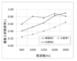
- the normal incidence sound absorption coefficient at 800 to 2000 Hz was measured with an air layer of 10 mm provided on the The results are shown in FIG.
- FIG. 2 the result obtained in Example 2 is written together for comparison.
- Example 5 The soundproof cover for an automobile engine obtained in Example 3 is cut out into a 1 m 2 flat plate and used as a measurement sample, and the side of the measurement sample is made of L-shaped aluminum by reverberation room Ab-Loss manufactured by Nippon Acoustic Engineering Co., Ltd.
- the sound absorption coefficient (reverberation chamber method sound absorption coefficient) was measured in the state (Example 5) in which the back air layer was provided 10 mm using a 10 mm spacer on the back surface of the measurement sample in a sealed state using an anchor.
- the sound absorption coefficient was measured in the range of 800 Hz to 2000 Hz using an impulse response integral method based on ISO 354 (2003). The results are shown in FIG.
- the soundproof covers for automobile engines obtained in Examples 1 to 4 have sufficient heat resistance made of a heat resistant material, and suppress the sound pressure in the frequency band of about 800 to 2000 Hz. It is understood that sound pressure in a frequency band of about 400 Hz to less than 800 Hz can be sufficiently suppressed.
Landscapes
- Physics & Mathematics (AREA)
- Acoustics & Sound (AREA)
- Engineering & Computer Science (AREA)
- Multimedia (AREA)
- Mechanical Engineering (AREA)
- Laminated Bodies (AREA)
- Soundproofing, Sound Blocking, And Sound Damping (AREA)
- Vehicle Interior And Exterior Ornaments, Soundproofing, And Insulation (AREA)
Abstract
耐熱性を有し、厚さが薄くても十分な防音性能を有する新規な防音用被覆材を提供する。 開孔率が0.1~5.0%で開孔径が100~1000μmである第一の多孔質フィルムと、一以上の弾性多孔質体層と、開孔率が0.1~5.0%で開孔径が100~1000μmである第二の多孔質フィルムとが、この順番に積層されてなることを特徴とする防音用被覆材である。
Description
本発明は、防音用被覆材およびエンジンユニットに関する。
近年、自動車騒音に関する基準調和について、国連の欧州経済委員会(ECE)の自動車基準調和世界フォーラムにおいて検討され、車両構造に関する規則の制定、改訂が行われている。
従来より、自動車メーカー各社は様々な防音仕様について開発を進めており、自動車エンジン用防音カバーとしても種々のものが提案されている(例えば、特許文献1(特開2002-180845号公報)参照)が、自動車の車外騒音については上記ECEの規則51(ECE R51)に規制値が定められ、同規制値を定めたRegulation EU No.540/2014によれば、2016年7月迄に72dB(フェーズ1)、2020年7月迄に70dB(フェーズ2)、2024年7月迄に68dB(フェーズ3)と段階を追って厳しくなる基準が施行され、車外騒音の規制レベルを最終的には2016年7月までの基準に対して4dB、音圧エネルギーとして約1/2.5に低減するという大変厳しい要求がなされている。
従来より、自動車メーカー各社は様々な防音仕様について開発を進めており、自動車エンジン用防音カバーとしても種々のものが提案されている(例えば、特許文献1(特開2002-180845号公報)参照)が、自動車の車外騒音については上記ECEの規則51(ECE R51)に規制値が定められ、同規制値を定めたRegulation EU No.540/2014によれば、2016年7月迄に72dB(フェーズ1)、2020年7月迄に70dB(フェーズ2)、2024年7月迄に68dB(フェーズ3)と段階を追って厳しくなる基準が施行され、車外騒音の規制レベルを最終的には2016年7月までの基準に対して4dB、音圧エネルギーとして約1/2.5に低減するという大変厳しい要求がなされている。
ところで、上記自動車の騒音は、エンジン、モーター、トランスミッション等駆動系エンジンルームから発生する騒音のみならず、排気音、風切音、タイヤロードノイズ等が合算したものであるため、エンジンルームから発生する騒音の低減のみで上記目標を達成しようとした場合、エンジンルームにおいて5~6dB、音圧エネルギーとして1/4に低減するという大きな騒音低減が必要になることから、従来の自動車エンジン用防音カバーでは対応が困難になってきている。
このように、従来提案されてきた防音カバーでは、益々厳しくなる規制水準に対し必ずしも十分な騒音抑制効果は得られ難い。
このような状況下、防音仕様として、例えば、エンジンのほぼ全体、すなわち、エンジン壁面・上面(ボンネット)側・下面(アンダーボディー)側のほぼ全面に防音材を施行し、音源となるエンジン全体を防音材で覆い車外への騒音漏洩を抑制すると同時にその吸音効果によりエンジンルーム内の騒音レベルを低減させる、(ニア)エンジンカプセル化による対応が考えられる。
しかしながら、ダウンサイジングを施した最近の車両のエンジンルーム内は各部品が高度に集積され、スペースが狭いために、上記カプセル化を行う場合においても防音材に用意された厚さは10~20mm程度と極く薄い一方で、防音材による吸音および遮音効果により騒音を低減しようとした場合、特に1kHz以下の比較的低周波数側の騒音は防音材の厚さ及び質量に依存するので、得られる効果は極く限定的なものとなる。そのため、前記の防音材を設置すると、1000Hzを超える高周波側の騒音のみが吸音され、低周波側の騒音が目立つこととなる。
防音材が十分な吸音性能を発揮できない場合、エンジンルーム内には大きな反響音が響き、遮音性能も十分でない場合には、減衰しきれないエネルギーがエンジンルームの壁面・上面・下面を振動させ、さらに大きな騒音が発生することもある。
このため、800~2000Hz程度の周波数帯における音圧を抑制し得るとともに、より音圧を低減するために400Hz以上800Hz未満程度の周波数帯における音圧も抑制し得る防音カバーが求められる。
また、例えば自動車エンジン用防音カバーにおいては、エンジンの排気側壁面及び上面の一部(燃焼排ガスが通過するエキゾースト・マニフォールド近傍)が排気ガスで加熱されることから、防音用被覆材としては150℃程度の耐熱性を有するものが求められる。
このような状況下、本発明は、耐熱性を有し、厚さが薄くても十分な防音性能を有する新規な防音用被覆材および係る防音用被覆材を有するエンジンユニットを提供することを目的とするものである。
上記目的を達成するために本発明者等が鋭意検討を行った結果、開孔率が0.1~5.0%で開孔径が100~1000μmである第一の多孔質フィルムと、一以上の弾性多孔質体層と、開孔率が0.1~5.0%で開孔径が100~1000μmである第二の多孔質フィルムとが、この順番に積層されてなる防音用被覆材により上記技術課題を解決し得ることを見出し、本知見に基づいて本発明を完成するに至った。
すなわち、本発明は、
(1)開孔率が0.1~5.0%で開孔径が100~1000μmである第一の多孔質フィルムと、一以上の弾性多孔質体層と、開孔率が0.1~5.0%で開孔径が100~1000μmである第二の多孔質フィルムとが、この順番に積層されてなることを特徴とする防音用被覆材、
(2)前記第一の多孔質フィルムの外表面側および第二の多孔質フィルムの外表面側の少なくとも一方にさらに表皮材を有する上記(1)に記載の防音用被覆材、
(3)前記第一の多孔質フィルムまたは第二の多孔質フィルムの通気抵抗が0.1~10kPa・s/mである上記(1)に記載の防音用被覆材、
(4)前記第一の多孔質フィルムまたは第二の多孔質フィルムの通気抵抗が0.1~10kPa・s/mである上記(2)に記載の防音用被覆材、
(5)前記防音用被覆材が自動車エンジン用防音カバーである上記(1)に記載の防音用被覆材、
(6)前記防音用被覆材が自動車エンジン用防音カバーである上記(2)に記載の防音用被覆材、
(7)前記防音用被覆材が自動車エンジン用防音カバーである上記(3)に記載の防音用被覆材、
(8)前記防音用被覆材が自動車エンジン用防音カバーである上記(4)に記載の防音用被覆材、
(9)自動車用エンジンと当該自動車用エンジンの少なくとも一部を覆う上記(1)~(8)のいずれかに記載の防音用被覆材と、前記自動車用エンジンと防音用被覆材とを収容するエンジンルームとを有するエンジンユニットであって、前記自動車用エンジンと前記防音用被覆材との間または前記防音用被覆材とエンジンルームとの間に0.1~30mmの距離の空隙を有すること
を特徴とするエンジンユニット、を提供するものである。
(1)開孔率が0.1~5.0%で開孔径が100~1000μmである第一の多孔質フィルムと、一以上の弾性多孔質体層と、開孔率が0.1~5.0%で開孔径が100~1000μmである第二の多孔質フィルムとが、この順番に積層されてなることを特徴とする防音用被覆材、
(2)前記第一の多孔質フィルムの外表面側および第二の多孔質フィルムの外表面側の少なくとも一方にさらに表皮材を有する上記(1)に記載の防音用被覆材、
(3)前記第一の多孔質フィルムまたは第二の多孔質フィルムの通気抵抗が0.1~10kPa・s/mである上記(1)に記載の防音用被覆材、
(4)前記第一の多孔質フィルムまたは第二の多孔質フィルムの通気抵抗が0.1~10kPa・s/mである上記(2)に記載の防音用被覆材、
(5)前記防音用被覆材が自動車エンジン用防音カバーである上記(1)に記載の防音用被覆材、
(6)前記防音用被覆材が自動車エンジン用防音カバーである上記(2)に記載の防音用被覆材、
(7)前記防音用被覆材が自動車エンジン用防音カバーである上記(3)に記載の防音用被覆材、
(8)前記防音用被覆材が自動車エンジン用防音カバーである上記(4)に記載の防音用被覆材、
(9)自動車用エンジンと当該自動車用エンジンの少なくとも一部を覆う上記(1)~(8)のいずれかに記載の防音用被覆材と、前記自動車用エンジンと防音用被覆材とを収容するエンジンルームとを有するエンジンユニットであって、前記自動車用エンジンと前記防音用被覆材との間または前記防音用被覆材とエンジンルームとの間に0.1~30mmの距離の空隙を有すること
を特徴とするエンジンユニット、を提供するものである。
本発明によれば、耐熱性を有し、厚さが薄くても十分な防音性能を有する新規な防音用被覆材および係る防音用被覆材を有するエンジンユニットを提供することができる。
先ず、本発明に係る防音用被覆材について説明する。
本発明に係る防音用被覆材は、開孔率が0.1~5.0%で開孔径が100~1000μmである第一の多孔質フィルムと、一以上の弾性多孔質体層と、開孔率が0.1~5.0%で開孔径が100~1000μmである第二の多孔質フィルムとが、この順番に積層されてなることを特徴とするものである。
本発明に係る防音用被覆材は、開孔率が0.1~5.0%で開孔径が100~1000μmである第一の多孔質フィルムと、一以上の弾性多孔質体層と、開孔率が0.1~5.0%で開孔径が100~1000μmである第二の多孔質フィルムとが、この順番に積層されてなることを特徴とするものである。
本発明に係る防音用被覆材において、第一の多孔質フィルムおよび第二の多孔質フィルムは、開孔率が0.1~5.0%で開孔径が100~1000μmであるものである。
本発明に係る防音用被覆材において、第一の多孔質フィルムおよび第二の多孔質フィルムは、同一のものであってもよいし異なるものであってもよい。
本発明に係る防音用被覆材において、第一の多孔質フィルムおよび第二の多孔質フィルムは、同一のものであってもよいし異なるものであってもよい。
本発明に係る防音用被覆材において、第一の多孔質フィルムまたは第二の多孔質フィルムの構成材料としては特に制限されず、所望の細孔分布を有するものを適宜選択すればよい。
第一の多孔質フィルムまたは第二の多孔質フィルムとしては、柔軟性を有し、後述する弾性多孔質体層を挟持した状態で、使用環境下において著しい熱収縮等を生じないものが好ましい。
第一の多孔質フィルムまたは第二の多孔質フィルムとしては、柔軟性を有し、後述する弾性多孔質体層を挟持した状態で、使用環境下において著しい熱収縮等を生じないものが好ましい。
このような多孔質フィルムとしては、ポリエチレンフィルムや、6-ナイロン製フィルム、6,6-ナイロン製フィルム、11-ナイロン製フィルム、12-ナイロン製フィルム等から選ばれるポリアミド(ナイロン)フィルムや、ポリエステルフィルム等の有機フィルム、短繊維不織布、長繊維クロス及び抄造紙等から選ばれる一種以上を挙げることができる。
本発明に係る防音用被覆材において、第一の多孔質フィルムまたは第二の多孔質フィルムは、多層フィルムにより構成されていてもよく、多層フィルムとしては、例えば、ポリアミド(ナイロン)フィルムの両面に低圧ポリエチレン接着層が配置されるように製造した共押し出し多層フィルム等を挙げることができる。
上記多層フィルムを使用することにより、後述する弾性多孔質体層への密着性等を容易に向上することができる。
また、第一の多孔質フィルムまたは第二の多孔質フィルムは、その通気性を制御するために、表面に適宜塗布剤を塗布加工したものであってもよい。
上記多層フィルムを使用することにより、後述する弾性多孔質体層への密着性等を容易に向上することができる。
また、第一の多孔質フィルムまたは第二の多孔質フィルムは、その通気性を制御するために、表面に適宜塗布剤を塗布加工したものであってもよい。
本発明に係る防音用被覆材において、第一の多孔質フィルムまたは第二の多孔質フィルムは、開孔率が、0.1~5.0%であるものであり、0.1 ~1.0%であるものが好ましく、0.1~0.5%であるものがより好ましい。
また、本発明に係る防音用被覆材において、第一の多孔質フィルムまたは第二の多孔質フィルムは、開孔径が100~1000μmであるものであり、300~800μmであるものが好ましく、500~700μmであるものがより好ましい。
また、本発明に係る防音用被覆材において、第一の多孔質フィルムまたは第二の多孔質フィルムは、開孔径が100~1000μmであるものであり、300~800μmであるものが好ましく、500~700μmであるものがより好ましい。
本出願書類において、第一の多孔質フィルムまたは第二の多孔質フィルムの開孔率(%)は、各多孔質フィルムの表面をマイクロスコープ((株)キーエンス、VHX-500)で観察した際に(孔の全面積/多孔質フィルムの面積)×100により算出される開孔割合の任意の50箇所における算術平均値を意味する。
なお、上記孔の全面積は、マイクロスコープにより測定した値を意味する。
なお、上記孔の全面積は、マイクロスコープにより測定した値を意味する。
また、本出願書類において、第一の多孔質フィルムまたは第二の多孔質フィルムの開孔径は、多孔質フィルムの表面をマイクロスコープで観察した際における50個の孔の最大直径の算術平均値を意味する。
本発明に係る防音用被覆材を構成する第一の多孔質フィルムまたは第二の多孔質フィルムが、上記開孔率および開孔径を有するものであることにより、外部から被覆材を音が通過する際の流れ抵抗を容易に制御し、所望の耐熱性を発揮しつつ、所望周波数、特に周波数400Hz以上800Hz未満における低周波音の音圧を容易に低減することができる。
すなわち、防音用被覆材の両主表面側に微通気性フィルム材(第一の多孔質フィルムおよび第二の多孔質フィルム)を配置することで、防音用積層材全体の流れ抵抗を調節し吸音性能を向上し得ると考えられる。
すなわち、防音用被覆材の両主表面側に微通気性フィルム材(第一の多孔質フィルムおよび第二の多孔質フィルム)を配置することで、防音用積層材全体の流れ抵抗を調節し吸音性能を向上し得ると考えられる。
本発明に係る防音用被覆材において、第一の多孔質フィルムまたは第二の多孔質フィルムの開孔部は、多孔質フィルムを構成するフィルム材をニードルパンチ処理したり熱剣山ロールを通過させる等の開孔処理を施すことにより形成することができ、上記多孔質フィルムの開孔率や開孔径も、上記開孔処理時の処理条件を制御することにより容易に制御することができる。
本発明に係る防音用被覆材において、第一の多孔質フィルムまたは第二の多孔質フィルムは、通気抵抗が、0.1~10kPa・s/mであるものが好ましく、0.5~5.0kPa・s/mであるものがより好ましく、0.5~1.5kPa・s/mであるものがさらに好ましい。
本出願書類において、第一の多孔質フィルムまたは第二の多孔質フィルムの通気抵抗は、多孔質フィルムの主表面に対して、垂直方向に0.4cc/cm2/sで空気を通過させたときにおける入口側および出口側における気圧を各々流れ抵抗測定器(製品名:KES-F8-AP1、カトーテック(株)製)で測定したときにおける両者の差(差圧)を流速で除したものを意味する。
本発明に係る防音用被覆材が、上記通気抵抗を有する第一の多孔質フィルムまたは第二の多孔質フィルムを有するものであることにより、外部から被覆材を音が通過する際の流れ抵抗を容易に制御して所望周波数、特に周波数400Hz以上800Hz未満における低周波音の音圧を容易に低減することができる。
本発明に係る防音用被覆材において、第一の多孔質フィルムまたは第二の多孔質フィルムのヤング率は、0.5GPa以下が好ましく、0.1GPa以下がより好ましく、0.05GPa以下がさらに好ましく、0.01GPa以下が一層好ましい。
多孔質フィルムのヤング率が上記範囲内にあることにより、多孔質フィルムが所望の柔軟性を有し、可撓性等に優れ、吸音性に優れた防音用被覆材を容易に提供することができる。
多孔質フィルムのヤング率が上記範囲内にあることにより、多孔質フィルムが所望の柔軟性を有し、可撓性等に優れ、吸音性に優れた防音用被覆材を容易に提供することができる。
本出願書類において、第一の多孔質フィルムまたは第二の多孔質フィルムのヤング率は、JIS K7127の規定に準拠して測定された値を意味する。
本発明に係る防音用被覆材において、第一の多孔質フィルムまたは第二の多孔質フィルムの厚みは、10~100μmであることが好ましく、10~80μmであることがより好ましく、30~70μmであることがさらに好ましい。
第一の多孔質フィルムまたは第二の多孔質フィルムの厚みが上記範囲内にあることにより、柔軟性に優れるとともに防音用被覆材の薄型化(コンパクト化)を容易に図ることができる。
第一の多孔質フィルムまたは第二の多孔質フィルムの厚みが上記範囲内にあることにより、柔軟性に優れるとともに防音用被覆材の薄型化(コンパクト化)を容易に図ることができる。
本発明に係る防音用被覆材は、中央部に弾性多孔質体層を有するとともに、その外側に各々第一の多孔質フィルムおよび第二の多孔質フィルムを有することにより、外部から被覆材を音が通過する際の流れ抵抗を容易に制御して所望周波数、特に周波数400Hz以上800Hz未満における低周波音の音圧を容易に低減することができる。
これは、外部から被覆材中を通過しようとする音に対し、多孔質フィルムに設けられた空孔により、専ら周波数が800~2000Hz程度の高周波音の音波は多孔質フィルム表面で反射されずに内部に取り込まれ、周波数が400Hz以上800Hz未満の低周波音の音波は多孔質フィルムに遮られて空気中を伝搬する音エネルギーが振動エネルギーに変換され、多孔質フィルムおよび被覆材全体の振動により吸音されると考えられる。
これは、外部から被覆材中を通過しようとする音に対し、多孔質フィルムに設けられた空孔により、専ら周波数が800~2000Hz程度の高周波音の音波は多孔質フィルム表面で反射されずに内部に取り込まれ、周波数が400Hz以上800Hz未満の低周波音の音波は多孔質フィルムに遮られて空気中を伝搬する音エネルギーが振動エネルギーに変換され、多孔質フィルムおよび被覆材全体の振動により吸音されると考えられる。
本発明に係る防音用被覆材は、上記弾性多孔質体層の上面側および下面側に各々第一の多孔性フィルムおよび第二の多孔質フィルムを有するものであることから、防音用被覆材の下面側から上面側に通過する音のみならず上面側から下面側に通過する音に対しても吸音特性を発揮することができる。
このため、例えば本発明に係る防音用被覆材を自動車エンジン用防音カバーとして使用した場合、自動車エンジンから発せられた音が防音用被覆材の下面側から上面側に通過する際に、自動車エンジンから発せられる周波数400Hz以上800Hz未満の低周波音の音波は被覆材の下側に配置された多孔質フィルムに遮られて吸音され、周波数400Hz以上800Hz未満の低周波音の一部が上記防音用被覆材を通過した場合であっても、自動車用エンジンと防音用被覆材とを収容するエンジンルームの壁面で反射して防音用被覆材の上面側から下面側に通過する際に、同様に被覆材の上側に配置された多孔質フィルムによって振動エネルギーに変換され、効果的に吸音性能を発揮することができる。
このため、例えば本発明に係る防音用被覆材を自動車エンジン用防音カバーとして使用した場合、自動車エンジンから発せられた音が防音用被覆材の下面側から上面側に通過する際に、自動車エンジンから発せられる周波数400Hz以上800Hz未満の低周波音の音波は被覆材の下側に配置された多孔質フィルムに遮られて吸音され、周波数400Hz以上800Hz未満の低周波音の一部が上記防音用被覆材を通過した場合であっても、自動車用エンジンと防音用被覆材とを収容するエンジンルームの壁面で反射して防音用被覆材の上面側から下面側に通過する際に、同様に被覆材の上側に配置された多孔質フィルムによって振動エネルギーに変換され、効果的に吸音性能を発揮することができる。
本発明に係る防音用被覆材は、第一の多孔質フィルムと、一以上の弾性多孔質体層と、第二の多孔質フィルムとが、この順番に積層されてなることを特徴とするものである。
本発明に係る防音用被覆材において、弾性多孔質体層が複数設けられる場合、より効果的に音圧を低減することができる。
本発明に係る防音用被覆材において、弾性多孔質体層を構成する弾性多孔質体としては、繊維集成体、フェルトおよび樹脂発泡体から選ばれる一種以上を挙げることができる。
上記繊維集成体としては、例えば、グラスウール(ガラス繊維)、ロックウール、シリカ繊維、シリカアルミナセラミックファイバー、アルミナ繊維、ムライト繊維等の無機短繊維からなる集成体を挙げることができる。
フェルトとしては、上記各種短繊維の一種以上を混合したものをニードルパンチ等の手段で一体化したものを挙げることができ、具体的には、もう集成体を形成する無機短繊維からなる無機繊維製フェルト(例えば、グラスウールからなるグラスフェルト(ガラス繊維フェルト)等の他、ポリエチレンテレフタレートフェルト等のポリエステル繊維フェルト、ナイロン繊維フェルト、ポリエチレン繊維フェルト、ポリプロピレン繊維フェルト、アクリル繊維フェルト、アラミド繊維フェルト、シリカーアルミナセラミックスファイバーフェルト、シリ力繊維フェルト、綿、羊毛、木毛、クズ繊維等を熱硬化性樹脂でフェルト状に加工したレジンフェルト等から選ばれる一種以上を挙げることができる。
フェルトとしては、無機繊維製フェルトが好ましく、密度が10~50kg/m3であるものが好ましく、15~50kg/m3であるものより好ましく、20~35kg/m3であるものがさらに好ましく、人造鉱物繊維の吹き付け物や成形物を使用することができる。
上記樹脂発泡体としては、ポリウレタンフォーム、ポリエチレンフォーム、ポリプロピレンフォーム、フェノールフォーム、メラミンフォーム等の樹脂フォームから選ばれる一種以上や、二トリルブタジエンラバー、クロロプレンラバー、スチレンラバー、シリコーンゴム、ウレタンゴム、エチレン・プロピレン・ジエンゴム等を連泡状に発泡させるか、発泡後にクラッシング加工などにより連泡化した連続気泡体から選ばれる一種以上を挙げることができる。
フェルトとしては、上記各種短繊維の一種以上を混合したものをニードルパンチ等の手段で一体化したものを挙げることができ、具体的には、もう集成体を形成する無機短繊維からなる無機繊維製フェルト(例えば、グラスウールからなるグラスフェルト(ガラス繊維フェルト)等の他、ポリエチレンテレフタレートフェルト等のポリエステル繊維フェルト、ナイロン繊維フェルト、ポリエチレン繊維フェルト、ポリプロピレン繊維フェルト、アクリル繊維フェルト、アラミド繊維フェルト、シリカーアルミナセラミックスファイバーフェルト、シリ力繊維フェルト、綿、羊毛、木毛、クズ繊維等を熱硬化性樹脂でフェルト状に加工したレジンフェルト等から選ばれる一種以上を挙げることができる。
フェルトとしては、無機繊維製フェルトが好ましく、密度が10~50kg/m3であるものが好ましく、15~50kg/m3であるものより好ましく、20~35kg/m3であるものがさらに好ましく、人造鉱物繊維の吹き付け物や成形物を使用することができる。
上記樹脂発泡体としては、ポリウレタンフォーム、ポリエチレンフォーム、ポリプロピレンフォーム、フェノールフォーム、メラミンフォーム等の樹脂フォームから選ばれる一種以上や、二トリルブタジエンラバー、クロロプレンラバー、スチレンラバー、シリコーンゴム、ウレタンゴム、エチレン・プロピレン・ジエンゴム等を連泡状に発泡させるか、発泡後にクラッシング加工などにより連泡化した連続気泡体から選ばれる一種以上を挙げることができる。
耐熱性を考慮した場合には、上記弾性多孔質体としては、ガラス繊維等の無機繊維またはアラミド繊維を構成繊維として含むものが好ましく、無機繊維を含むものがより好ましい。
本発明に係る防音用被覆材において、弾性多孔質体層を構成する弾性多孔質体としては、ガラス繊維を構成繊維として含むものが好ましく、上記ガラス繊維としては、繊維径が、0.1~4μmであるものが好ましく、0.1~2μmであるものがより好ましく、0.1~1μmであるものがさらに好ましい。
上記繊維径を有するガラス繊維は、遠心法または火炎法で製造することができる。
上記繊維径を有するガラス繊維は、遠心法または火炎法で製造することができる。
なお、本出願書類において、ガラス繊維の繊維径は、マイクロスコープにより測定した20本のガラス繊維の最大径の算術平均値を意味する。
本発明に係る防音用被覆材において、弾性多孔質体層を構成する弾性多孔質体が上記繊維径を有するガラス繊維を構成繊維として含むことにより、所望の耐熱性、難燃性をより容易に発揮することができる。
本発明に係る防音用被覆材において、弾性多孔質体層を構成する弾性多孔質体が、構成繊維として上記繊維径を有するガラス繊維を構成繊維として含む場合、弾性多孔質体は、ガラス繊維を、例えばノボラック、レゾール、ベンジリックエーテル系等から選ばれるフェノール樹脂や、尿素変性等の変性フェノール樹脂等からなるバインダーで固定してなるものであってもよいし、または、ニードルパンチ等の処理によりガラス繊維を厚さ方向に絡めることにより製造してなるものであってもよい。
本発明に係る防音用被覆材において、弾性多孔質体層を構成する弾性多孔質体として、ポリエステル繊維を構成繊維として含むものである場合、当該ポリエステル繊維としては難燃性ポリエステル繊維が好ましい。
上記難燃性ポリエステル繊維としては、ポリエチレンテレフタレート(PET)、ポリブチレンテレフタレート(PBT)、ポリエチレンイソフタレート(PEI)、ポリシクロヘキシレンジメチレンテレフタレート(PCHDT)またはポリエチレンナフタレート(PEN)等を主たる繰返し単位とするポリエステルを挙げることができる。
上記難燃性ポリエステル繊維としては、公知のものを挙げることもでき、例えば、特開昭51-82392号公報、特開昭55-7888号公報、特公昭55-41610号公報等に記載されたものを挙げることができる。
本発明に係る防音用被覆材において、弾性多孔質体層を構成する弾性多孔質体が、ポリエステル繊維を構成繊維として含むものである場合、当該ポリエステル繊維としては難燃性ポリエステルと熱接着性ポリエステルとが複合されてなる難燃性複合繊維であってもよい。
上記難燃性ポリエステルと熱接着性ポリエステルとが複合されてなる難燃性複合繊維において、難燃性ポリエステルとしては、上述した難燃性ポリエステル繊維を構成するものと同様のものを挙げることができる。
また、上記難燃性複合繊維において、熱接着性ポリエステルは、難燃性ポリエステルのバインダーとして機能するものであって、難燃性ポリエステルの融点よりも低い融点を有し、難燃性ポリエステルの融点よりも少なくとも20℃低い融点を有するものが好ましい。
上記融点の差が20℃未満であると、難燃性複合繊維の作製時に高温処理が必要になるために難燃性ポリエステルの配向性が低下し易くなり、熱接着性ポリエステルによる補強効果が低減して難燃剤内添繊維の耐久性が低下し易くなるとともに、母材である難燃性ポリエステルの物性低下を生じ易くなる。
また、上記難燃性複合繊維において、熱接着性ポリエステルは、難燃性ポリエステルのバインダーとして機能するものであって、難燃性ポリエステルの融点よりも低い融点を有し、難燃性ポリエステルの融点よりも少なくとも20℃低い融点を有するものが好ましい。
上記融点の差が20℃未満であると、難燃性複合繊維の作製時に高温処理が必要になるために難燃性ポリエステルの配向性が低下し易くなり、熱接着性ポリエステルによる補強効果が低減して難燃剤内添繊維の耐久性が低下し易くなるとともに、母材である難燃性ポリエステルの物性低下を生じ易くなる。
上記熱接着性ポリエステルは、融点が110℃~220℃であるものが好ましく、130℃~200℃であるものがより好ましい。熱接着性ポリエステルの融点が上記範囲内にあることによって補強効果を発揮し易くなる。
なお、本出願書類において、難燃性ポリエステルの融点および熱接着性ポリエステルの融点とは、繊維化物を熱板上に十字状に配置し、室温から5℃/分で昇温したときに、配向により生じる縞模様が焼失する温度を意味するものとする。
上記熱接着性ポリエステルとしては、特に制限されないが、例えば、テレフタル酸、イソフタル酸、フタル酸、p-ヒドロキシ安息香酸、5-ナトリウムスルホイソフタル酸、ナフタレンジカルボン酸、シュウ酸、アジピン酸、セバチン酸、シクロヘキシレンジカルボン酸等から選ばれる一種以上の酸成分と、エチレングリコール、ジエチレングリコール、トリエチレングリコール、プロパンジオール、ブタンジオール、ペンタンジオール、ヘキサンジオール、ネオペンチルグリコール、ポリエチレングリコール等から選ばれる一種以上のグリコール成分とをエステル結合させてなるものが挙げられる。
本発明に係る防音用被覆材において、弾性多孔質体層を構成する弾性多孔質体が、上記難燃性ポリエステルおよび熱接着性ポリエステルが複合されてなる難燃性複合繊維を構成繊維として有するものである場合、難燃性ポリエステルと熱接着性ポリエステルの複合割合は特に制限されないが、難燃性ポリステルの含有割合が20~80質量%であるものが好ましく、30~70質量%であるものがより好ましく、40~60質量%であるものがさらに好ましい。
難燃性複合繊維を構成する難燃性ポリエステルの含有割合が上記範囲内にあることにより、難燃性複合繊維に対して所望の難燃性を容易に付与することができる。
難燃性複合繊維を構成する難燃性ポリエステルの含有割合が上記範囲内にあることにより、難燃性複合繊維に対して所望の難燃性を容易に付与することができる。
上記難燃性ポリエステルおよび熱接着性ポリエステルの複合形態としては、難燃性ポリエステルをコア成分とし熱接着性ポリエステルをシース成分とするシースコア型、難燃性ポリエステルおよび熱接着性ポリエステルが隣接配置された層状多層構造型やサイドバイサイド型等を挙げることができる。
本発明に係る防音用被覆材において、弾性多孔質体層の厚みは、0.5~20mmであることが好ましく、1.5~15mmであることがより好ましく、3~10mmであることがさらに好ましい。
本発明に係る防音用被覆材において、弾性多孔質体層が複数層からなるものである場合は、複数の弾性多孔質体層の厚みの合計が上記範囲内にあればよい。
本発明に係る防音用被覆材において、弾性多孔質体層が複数層からなるものである場合は、複数の弾性多孔質体層の厚みの合計が上記範囲内にあればよい。
本発明に係る防音用被覆材において、弾性多孔質体層の厚みが上記範囲内にあることにより、柔軟性に優れるとともに防音用被覆材の薄型化(コンパクト化)を図りつつ十分な吸音性を容易に発揮することができる。
本発明に係る防音用被覆材において、弾性多孔質体層を構成する弾性多孔質体の嵩密度は、0.001~1.2g/cm3であることが好ましく、0.01~0.5g/cm3であることがより好ましく、0.025~0.1g/cm3であることがさらに好ましい。
上記嵩密度は、弾性多孔質体の構造および厚み等に応じて、所望の吸音性を有するものから適宜選択される。
上記嵩密度は、弾性多孔質体の構造および厚み等に応じて、所望の吸音性を有するものから適宜選択される。
上記密度を達成する上で、弾性多孔質体層を構成する弾性多孔質体の目付は、10~1000g/m2であることが好ましく、15~500g/m2であることがより好ましく、25~250g/m2であることがさらに好ましい。
弾性多孔質体の目付が上記範囲内にあることにより、軽量で所望形状を有する防音用被覆材を容易に提供することができる。
弾性多孔質体の目付が上記範囲内にあることにより、軽量で所望形状を有する防音用被覆材を容易に提供することができる。
本発明に係る防音用被覆材は、外部から被覆材中を通過しようとする音に対し、専ら周波数が400Hz以上800Hz未満の低周波音を、多孔質フィルムにより振動エネルギーに変換して吸音するとともに、専ら周波数が800~2000Hz程度の高周波音を、上記多孔質フィルムの空孔を通過させた後、内部に配置した弾性多孔質体層により吸音すると考えられる。
本発明に係る防音用被覆材は、上記弾性多孔質体層の上面側および下面側に各々第一の多孔性フィルムおよび第二の多孔質フィルムを有するものであることから、防音用被覆材の下面側から上面側に通過する音のみならず上面側から下面側に通過する音に対しても吸音特性を発揮することができる。
このため、例えば本発明に係る防音用被覆材を自動車エンジン用防音カバーとして使用した場合、自動車エンジンから発せられた音が防音用被覆材の下面側から上面側に通過する際に、自動車エンジンから発せられる周波数800~2000Hzの音波は被覆材の下側に配置された多孔質フィルムを通過して内部に配置された弾性多孔質体層で吸音され、周波数800~2000Hzの音波の一部が上記防音用被覆材を通過した場合であっても、自動車用エンジンと防音用被覆材とを収容するエンジンルームの壁面で反射して防音用被覆材の上面側から下面側に通過する際に、同様に被覆材の上側に配置された多孔質フィルムを通過して同様に内部に配置された弾性多孔質体層で吸音されてさらに効果的に吸音性能を発揮することができると考えられる。
このため、例えば本発明に係る防音用被覆材を自動車エンジン用防音カバーとして使用した場合、自動車エンジンから発せられた音が防音用被覆材の下面側から上面側に通過する際に、自動車エンジンから発せられる周波数800~2000Hzの音波は被覆材の下側に配置された多孔質フィルムを通過して内部に配置された弾性多孔質体層で吸音され、周波数800~2000Hzの音波の一部が上記防音用被覆材を通過した場合であっても、自動車用エンジンと防音用被覆材とを収容するエンジンルームの壁面で反射して防音用被覆材の上面側から下面側に通過する際に、同様に被覆材の上側に配置された多孔質フィルムを通過して同様に内部に配置された弾性多孔質体層で吸音されてさらに効果的に吸音性能を発揮することができると考えられる。
本発明に係る防音用被覆材は、第一の多孔質フィルムの外表面側および第二の多孔質フィルムの外表面側の少なくとも一方にさらに表皮材を有するものであってもよい。
本発明に係る防音用被覆材において、表皮材は、第一の多孔質フィルムの外表面側および第二の多孔質フィルムの外表面側の少なくとも一方に設けられていることが好ましく、両者に設けられていることがより好ましい。
本発明に係る防音用被覆材において、表皮材は、第一の多孔質フィルムの外表面側および第二の多孔質フィルムの外表面側の少なくとも一方に設けられていることが好ましく、両者に設けられていることがより好ましい。
本発明に係る防音用被覆材において、第一の多孔質フィルムの外表面側および第二の多孔質フィルムの外表面側の両者に表皮材が設けられる場合、両表皮材は同一であってもよいし異なっていてもよい。
表皮材としては、温度150℃で溶融や著しい収縮等の不具合が生じないのであれば、難燃性ポリエステル繊維製不織布、無機長繊維クロス、無機繊維製シートや開孔処理を施した金属箔樹脂シート等から選ばれる一種以上を配置することができる。
上記難燃性ポリエステル繊維製不織布を構成する難燃性ポリエステル繊維としては、ポリエチレンテレフタレート(PET)、ポリブチレンテレフタレート(PBT)、ポリエチレンイソフタレート(PEI)、ポリシクロヘキシレンジメチレンテレフタレート(PCHDT)またはポリエチレンナフタレート(PEN)等を主たる繰返し単位とするポリエステルを挙げることができる。
上記難燃性ポリエステル繊維としては、公知のものを挙げることもでき、例えば、特開昭51-82392号公報、特開昭55-7888号公報、特公昭55-41610号公報等に記載されたものを挙げることができる。
上記難燃性ポリエステル繊維としては、公知のものを挙げることもでき、例えば、特開昭51-82392号公報、特開昭55-7888号公報、特公昭55-41610号公報等に記載されたものを挙げることができる。
また、無機長繊維クロスとしては、ガラス繊維、シリカ繊維、バサルト繊維、シリカアルミナセラミックファイバー、アルミナ繊維、ムライト繊維等の無機繊維から選ばれる一種以上をクロス状に編み込んだものを挙げることができ、無機繊維製シートとしては、上記無機繊維からから選ばれる一種以上をニードルパンチ等の手段で一体化したものを挙げることができる。
さらに、開孔処理を施した金属箔樹脂シートとしては、表面に微細な開孔を施して音の反射を抑制したアルミニウム箔等の金属箔等が、意匠性や振動による繊維の飛散防止等の観点から好適である。
さらに、開孔処理を施した金属箔樹脂シートとしては、表面に微細な開孔を施して音の反射を抑制したアルミニウム箔等の金属箔等が、意匠性や振動による繊維の飛散防止等の観点から好適である。
表皮材の通気抵抗は、入射音波の表面側の反射を抑制するために、繊維飛散防止等の効果を妨げない範囲内のものであればよく、1.0kPa・s/m以下であるものが好ましく、0.5kPa・s/m以下であるものがより好ましく、0.3kPa・s/m以下であるものがさらに好ましい。
上記通気抵抗は、繊維も編み方や金属箔の開孔の程度等により適宜調整することができる。
上記通気抵抗は、繊維も編み方や金属箔の開孔の程度等により適宜調整することができる。
本出願書類において、表皮材の通気抵抗は、表皮材の主表面に対して垂直方向に0.4cc/ cm2 / sで空気を通過させたときにおける入口側および出口側における気圧を各々流れ抵抗測定器(製品名:KES-F8-AP1、カトーテック(株)製)で測定したときにおける両者の差(差圧)を流速で除したものを意味する。
無機繊維製シートとしては、例えば、ガラス繊維および樹脂バインダーを含むガラス繊維フェルトを挙げることができ、係るガラス繊維フェルトを構成する樹脂バインダーとしては、含有量が5質量%未満であるノボラック、レゾール、ベンジリックエーテル系等のフェノール樹脂や、含有量が10~20質量%である尿素変性等の変性フェノール樹脂を挙げることができる。
表皮材として無機繊維製シートを用いた場合、所望の吸音性を発揮しつつ、優れた耐熱性および断熱性を容易に発揮することができる。
また、表皮材として金属箔を用いた場合、所望の吸音性を発揮するために、開孔率が、3%~7%であるものが好ましく、4%~7%であるものがより好ましく、5%~7%であるものがより好ましい。
また、本発明に係る防音用被覆材において、金属箔には止液性が確保できる範囲で、開孔径が、1μm以上であるものが好ましく、5μm以上であるものがより好ましく、10μm以上であるものがさらに好ましい。
表皮材の開孔率や開孔径は、上述した多孔質フィルムの開孔率や開孔径の測定方法と同様の測定方法で測定することができる。
また、本発明に係る防音用被覆材において、金属箔には止液性が確保できる範囲で、開孔径が、1μm以上であるものが好ましく、5μm以上であるものがより好ましく、10μm以上であるものがさらに好ましい。
表皮材の開孔率や開孔径は、上述した多孔質フィルムの開孔率や開孔径の測定方法と同様の測定方法で測定することができる。
本発明に係る防音用被覆材が、表皮材を有するものである場合、形状安定性や意匠性を確保し易くなるとともに、使用時において被覆材を構成する繊維等の飛散を抑制し得るとともに、容易に撥水性を発揮することができる。
本発明に係る防音用被覆材は、厚さが、5~20mmであるものが適当であり、10~20mmであるものがより適当であり、15~20mmであるものがさらに適当である。
本発明に係る防音用被覆材は、厚さが薄くても十分な防音性能を発揮することができる。
本発明に係る防音用被覆材は、厚さが薄くても十分な防音性能を発揮することができる。
本発明に係る防音用被覆材が、上記通気抵抗を有するものであることにより、流れ抵抗を容易に制御して所望周波数、特に周波数400Hz以上800Hz未満近傍における音圧および周波数800~2000Hz近傍における音圧を容易に低減することができる。
本発明に係る防音用被覆材は、例えば、得ようとする防音用被覆材の構成部材に対応する形成材の全部を順次積層した状態で所定形状に熱圧成形することにより作製することができる。
また、本発明に係る防音用被覆材は、例えば、得ようとする防音用被覆材の構成部材に対応する全形成材のうち一部のみを順次積層した状態で所定形状に熱圧成形したものと、得ようとする防音用被覆材の構成部材に対応する他の形成材を順次積層した状態で所定形状に熱圧成形したものを、適宜接着剤等で固定することにより作製することができる。
また、本発明に係る防音用被覆材は、例えば、得ようとする防音用被覆材の構成部材に対応する全形成材のうち一部のみを順次積層した状態で所定形状に熱圧成形したものと、得ようとする防音用被覆材の構成部材に対応する他の形成材を順次積層した状態で所定形状に熱圧成形したものを、適宜接着剤等で固定することにより作製することができる。
具体的には、本発明に係る防音用被覆材として、例えば、(1)第一の多孔質フィルム、(2)弾性多孔質体層、(3)第二の多孔性フィルムがこの順番で順次積層されてなる防音用被覆材を形成する場合、これ等を各々形成する形成材をこの順番で順次積層した状態で所定形状に熱圧成形することにより作製することができる。
また、(1)第一の表皮材、(2)第一の多孔質フィルム、(3)弾性多孔質体層、(4)第二の多孔質フィルムがこの順番で順次積層されてなる防音用被覆材を形成する場合、例えば、これ等を各々形成する形成材をこの順番で順次積層した状態で所定形状に熱圧成形することにより作製することができる。
さらに、(1)第一の表皮材、(2)第一の多孔質フィルム、(3)弾性多孔質体層、(4)第二の多孔質フィルム、(5)第二の表皮材がこの順番で順次積層されてなる防音用被覆材を形成する場合、例えば、これ等を各々形成する形成材をこの順番で順次積層した状態で所定形状に熱圧成形することにより作製することができる。
加えて、(1)第一の表皮材、(2)第一の多孔質フィルム、(3)第一の弾性多孔質体層、(4)第二の弾性多孔質体層、(5)第二の多孔質フィルム、(6)第二の表皮材がこの順番で順次積層されてなる防音用被覆材を形成する場合、例えば、これ等を各々形成する形成材をこの順番で順次積層した状態で所定形状に熱圧成形することにより作製することができる。
また、(1)第一の表皮材、(2)第一の多孔質フィルム、(3)弾性多孔質体層、(4)第二の多孔質フィルムがこの順番で順次積層されてなる防音用被覆材を形成する場合、例えば、これ等を各々形成する形成材をこの順番で順次積層した状態で所定形状に熱圧成形することにより作製することができる。
さらに、(1)第一の表皮材、(2)第一の多孔質フィルム、(3)弾性多孔質体層、(4)第二の多孔質フィルム、(5)第二の表皮材がこの順番で順次積層されてなる防音用被覆材を形成する場合、例えば、これ等を各々形成する形成材をこの順番で順次積層した状態で所定形状に熱圧成形することにより作製することができる。
加えて、(1)第一の表皮材、(2)第一の多孔質フィルム、(3)第一の弾性多孔質体層、(4)第二の弾性多孔質体層、(5)第二の多孔質フィルム、(6)第二の表皮材がこの順番で順次積層されてなる防音用被覆材を形成する場合、例えば、これ等を各々形成する形成材をこの順番で順次積層した状態で所定形状に熱圧成形することにより作製することができる。
本発明に係る防音用被覆材は、例えば、自動車エンジン用防音カバーとして好適に使用することができる。
本発明に係る防音用被覆材を自動車エンジン用防音カバーとして使用する場合、例えば、エンジンの排気側壁面および上面の少なくとも一部に配置することにより、好適な吸音特性を容易に発揮することができる。
本発明に係る防音用被覆材を自動車エンジン用防音カバーとして使用する場合、例えば、エンジンの排気側壁面および上面の少なくとも一部に配置することにより、好適な吸音特性を容易に発揮することができる。
本発明によれば、耐熱性を有し、厚さが薄くても十分な防音性能を有する新規な防音用被覆材を提供することができる。
次に、本発明に係るエンジンユニットについて説明する。
本発明に係るエンジンユニットは、自動車用エンジンと当該自動車用エンジンの少なくとも一部を覆う本発明に係る防音用被覆材と、上記自動車用エンジンと防音用被覆材とを収容するエンジンルームとを有するエンジンユニットであって、上記自動車用エンジンと上記防音用被覆材との間または前記防音用被覆材とエンジンルームとの間に0.1~30mmの距離の空隙を有することを特徴とするものである。
本発明に係るエンジンユニットは、自動車用エンジンと当該自動車用エンジンの少なくとも一部を覆う本発明に係る防音用被覆材と、上記自動車用エンジンと防音用被覆材とを収容するエンジンルームとを有するエンジンユニットであって、上記自動車用エンジンと上記防音用被覆材との間または前記防音用被覆材とエンジンルームとの間に0.1~30mmの距離の空隙を有することを特徴とするものである。
本発明に係るエンジンユニットにおいて、本発明に係る防音用被覆材の詳細は上述したとおりである。
また、本発明に係るエンジンユニットにおいて、自動車用エンジンやエンジンルームは、公知のものを適宜採用することができる。
また、本発明に係るエンジンユニットにおいて、自動車用エンジンやエンジンルームは、公知のものを適宜採用することができる。
本発明に係るエンジンユニットにおいて、自動車用エンジンと防音用被覆材との間または防音用被覆材とエンジンルームとの間の距離(自動車用エンジンおよび防音用被覆材間に形成される隙間の幅または防音用被覆材およびエンジンルームの壁面間に形成される隙間)は、0.1mm以上であり、5mm以上が好ましく、10mm以上がより好ましい。
本発明に係るエンジンユニットにおいて、防音用被覆材が各々所定の開孔率および開孔径を有する第一の多孔質フィルムおよび第二の多孔質フィルムを有し、防音用被覆材を通過する音波に所定の流れ抵抗が生じ、自動車用エンジンと防音用被覆材との間または防音用被覆材とエンジンルームとの間の距離が上記範囲内にあることにより、自動車エンジンから発生して防音用被覆材を通過する音だけではなく、エンジンルームの壁面で反射し防音用被覆材を通過する音に対しても、多孔質フィルムによって効率的に振動へ変換され、エネルギーが減衰されることで、エンジンルーム内の音圧を好適に低減することができると考えられる。
本発明によれば、耐熱性を有し、厚さが薄くても十分な防音性能を有する防音用被覆材を有する新規なエンジンユニットを提供することができる。
次に、実施例を挙げて、本発明を更に具体的に説明するが、これは単に例示であって、本発明を制限するものではない。
(実施例1)
(1)第一の表皮材として、ポリエステル繊維フェルト(前田工繊(株)製125H、繊維径10μm、密度125kg/m3、目付量125g/m2、厚さ1mm)と、(2)第一の多孔質フィルムの形成材として、6-ナイロン製フィルム(宇部フィルム(株)製シュペレン35N-LL、密度900kg/m3、厚さ0.07mm)を熱剣山ロールを通過させることによって開孔部を設けたフィルム(開孔率4.1%、開孔径290μm、流れ抵抗 0.10kPa・s/m)と、
(3)第一の弾性多孔質体の形成材として、ポリエステル繊維フェルト(高安(株)製S250-HSGYN、ポリエステル繊維の平均繊維径10μm、密度25kg/m3、目付量250g/m2、厚さ10mm)と、
(4)第二の弾性多孔質体の形成材として、ポリエステル繊維フェルト(高安(株)製S250-HSGYN、ポリエステル繊維の平均繊維径10μm、密度25kg/m3、目付量250g/m2、厚さ10mm)と、
(5)第二の多孔質フィルムの形成材として、6-ナイロン製フィルム(宇部フィルム(株)製シュペレン35N-LL、密度900kg/m3、厚さ0.07mm)を熱剣山ロールを通過させることによって開孔部を設けたフィルム(開孔率4.1%、開孔径290μm、流れ抵抗0.10kPa・s/m)と、
(6)第二の表皮材として、ポリエステル繊維フェルト(前田工繊(株)製125H、繊維径10μm、密度125kg/m3、目付量125g/m2、厚さ1mm)とを、
この順番で順次配置し、5MPaの加圧力下、185℃で30秒間熱圧成形することにより、最大厚さ10mmの自動車エンジン用防音カバーを得た。
(1)第一の表皮材として、ポリエステル繊維フェルト(前田工繊(株)製125H、繊維径10μm、密度125kg/m3、目付量125g/m2、厚さ1mm)と、(2)第一の多孔質フィルムの形成材として、6-ナイロン製フィルム(宇部フィルム(株)製シュペレン35N-LL、密度900kg/m3、厚さ0.07mm)を熱剣山ロールを通過させることによって開孔部を設けたフィルム(開孔率4.1%、開孔径290μm、流れ抵抗 0.10kPa・s/m)と、
(3)第一の弾性多孔質体の形成材として、ポリエステル繊維フェルト(高安(株)製S250-HSGYN、ポリエステル繊維の平均繊維径10μm、密度25kg/m3、目付量250g/m2、厚さ10mm)と、
(4)第二の弾性多孔質体の形成材として、ポリエステル繊維フェルト(高安(株)製S250-HSGYN、ポリエステル繊維の平均繊維径10μm、密度25kg/m3、目付量250g/m2、厚さ10mm)と、
(5)第二の多孔質フィルムの形成材として、6-ナイロン製フィルム(宇部フィルム(株)製シュペレン35N-LL、密度900kg/m3、厚さ0.07mm)を熱剣山ロールを通過させることによって開孔部を設けたフィルム(開孔率4.1%、開孔径290μm、流れ抵抗0.10kPa・s/m)と、
(6)第二の表皮材として、ポリエステル繊維フェルト(前田工繊(株)製125H、繊維径10μm、密度125kg/m3、目付量125g/m2、厚さ1mm)とを、
この順番で順次配置し、5MPaの加圧力下、185℃で30秒間熱圧成形することにより、最大厚さ10mmの自動車エンジン用防音カバーを得た。
(実施例2)
実施例1において、(2)第一の多孔質フィルムの形成材および(5)第二の多孔質フィルムの形成材の開孔率を1.7%、開孔径を438μm、流れ抵抗を0.57kPa・s/mに改めた以外は、実施例1と同様にして最大厚さ10mmの自動車エンジン用防音カバーを得た。
実施例1において、(2)第一の多孔質フィルムの形成材および(5)第二の多孔質フィルムの形成材の開孔率を1.7%、開孔径を438μm、流れ抵抗を0.57kPa・s/mに改めた以外は、実施例1と同様にして最大厚さ10mmの自動車エンジン用防音カバーを得た。
(実施例3)
実施例1において、(2)第一の多孔質フィルムの形成材および(5)第二の多孔質フィルムの形成材の開孔率を1.3%、開孔径を690μm、流れ抵抗を1.27kPa・s/mに改めた以外は、実施例1と同様にして最大厚さ10mmの自動車エンジン用防音カバーを得た。
実施例1において、(2)第一の多孔質フィルムの形成材および(5)第二の多孔質フィルムの形成材の開孔率を1.3%、開孔径を690μm、流れ抵抗を1.27kPa・s/mに改めた以外は、実施例1と同様にして最大厚さ10mmの自動車エンジン用防音カバーを得た。
(実施例4)
実施例1において、(2)第一の多孔質フィルムの形成材および(5)第二の多孔質フィルムの形成材の開孔率を0.4%、開孔径を308μm、流れ抵抗を9.99kPa・s/mに改めた以外は、実施例1と同様にして最大厚さ10mmの自動車エンジン用防音カバーを得た。
実施例1において、(2)第一の多孔質フィルムの形成材および(5)第二の多孔質フィルムの形成材の開孔率を0.4%、開孔径を308μm、流れ抵抗を9.99kPa・s/mに改めた以外は、実施例1と同様にして最大厚さ10mmの自動車エンジン用防音カバーを得た。
(吸音性評価)
実施例1~実施例4で得られた自動車エンジン用防音カバーを用い、JIS-A-1415の規定に基づきブリュエル・ケアー・ジャパン製4206型音響管を用いて、各自動車エンジン用防音カバーの背後に10mmの空気層を設けた状態で、500~6400Hzにおける垂直入射吸音率を測定した。結果を図1に示す。
実施例1~実施例4で得られた自動車エンジン用防音カバーを用い、JIS-A-1415の規定に基づきブリュエル・ケアー・ジャパン製4206型音響管を用いて、各自動車エンジン用防音カバーの背後に10mmの空気層を設けた状態で、500~6400Hzにおける垂直入射吸音率を測定した。結果を図1に示す。
(比較例1)
実施例1において、(2)第一の多孔質フィルムの形成材および(5)第二の多孔質フィルムの形成材を用いなかった以外は、実施例1と同様にして最大厚さ10mmの自動車エンジン用防音カバーを得た。
実施例1において、(2)第一の多孔質フィルムの形成材および(5)第二の多孔質フィルムの形成材を用いなかった以外は、実施例1と同様にして最大厚さ10mmの自動車エンジン用防音カバーを得た。
(比較例2)
実施例1において、(2)第一の多孔質フィルムの形成材および(5)第二の多孔質フィルムの形成材を用いず、(3)第一の弾性多孔質体および(4)第二の弾性多孔質体の形成材間に、開孔率1.2%、開孔径730μm、流れ抵抗 0.45kPa・s/mの多孔質フィルムを配置した以外は、実施例1と同様にして最大厚さ10mmの自動車エンジン用防音カバーを得た。
実施例1において、(2)第一の多孔質フィルムの形成材および(5)第二の多孔質フィルムの形成材を用いず、(3)第一の弾性多孔質体および(4)第二の弾性多孔質体の形成材間に、開孔率1.2%、開孔径730μm、流れ抵抗 0.45kPa・s/mの多孔質フィルムを配置した以外は、実施例1と同様にして最大厚さ10mmの自動車エンジン用防音カバーを得た。
(吸音性評価)
比較例1~比較例2で得られた自動車エンジン用防音カバーを用い、JIS-A-1415の規定に基づきブリュエル・ケアー・ジャパン製4206型音響管を用いて、各自動車エンジン用防音カバーの背後に10mmの空気層を設けた状態で、800~2000Hzにおける垂直入射吸音率を測定した。結果を図2に示す。
なお、図2においては、比較のために、実施例2で得られた結果を併記している。
比較例1~比較例2で得られた自動車エンジン用防音カバーを用い、JIS-A-1415の規定に基づきブリュエル・ケアー・ジャパン製4206型音響管を用いて、各自動車エンジン用防音カバーの背後に10mmの空気層を設けた状態で、800~2000Hzにおける垂直入射吸音率を測定した。結果を図2に示す。
なお、図2においては、比較のために、実施例2で得られた結果を併記している。
(実施例5)
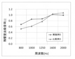
実施例3で得られた自動車エンジン用防音カバーを1m2の平板状に切り出して測定サンプルとし、日本音響エンジニアリング(株)製残響室Ab-Lossにより、測定サンプルの側面をL字状のアルミ製アンクルを用いてシールした状態で、測定サンプルの背面に10mmのスペーサーを用いて、背後空気層を10mm設けた状態(実施例5)において、吸音率(残響室法吸音率)を測定した。吸音率は800Hz~2000Hzの範囲においてISO354(2003)に基づくインパルス応答積分法を用いて測定した。結果を図3に示す。
実施例3で得られた自動車エンジン用防音カバーを1m2の平板状に切り出して測定サンプルとし、日本音響エンジニアリング(株)製残響室Ab-Lossにより、測定サンプルの側面をL字状のアルミ製アンクルを用いてシールした状態で、測定サンプルの背面に10mmのスペーサーを用いて、背後空気層を10mm設けた状態(実施例5)において、吸音率(残響室法吸音率)を測定した。吸音率は800Hz~2000Hzの範囲においてISO354(2003)に基づくインパルス応答積分法を用いて測定した。結果を図3に示す。
(比較例3)
実施例5において、実施例3で得られた自動車エンジン用防音カバーに代えて比較例32で得られた自動車エンジン用防音カバーを用いた以外は、実施例5と同様の方法で、背後空気層を10mm設けた状態における吸音率(残響室法吸音率)を測定した。結果を図3に示す。
実施例5において、実施例3で得られた自動車エンジン用防音カバーに代えて比較例32で得られた自動車エンジン用防音カバーを用いた以外は、実施例5と同様の方法で、背後空気層を10mm設けた状態における吸音率(残響室法吸音率)を測定した。結果を図3に示す。
図1および図3より、実施例1~実施例4で得られた自動車エンジン用防音カバーは、耐熱材料からなる十分な耐熱性を有し、800~2000Hz程度の周波数帯における音圧を抑制し得るとともに、400Hz以上800Hz未満程度の周波数帯における音圧も十分に抑制し得るものであることが分かる。
一方、図2および図3より、比較例1~比較例3で得られた自動車エンジン用防音カバーは、800~2000Hz程度の周波数帯における音圧を十分に抑制し得ないものであることが分かる。
本発明によれば、耐熱性を有し、厚さが薄くても十分な防音性能を有する新規な防音用被覆材および係る防音用被覆材を有するエンジンユニットを提供することができる。
Claims (9)
- 開孔率が0.1~5.0%で開孔径が100~1000μmである第一の多孔質フィルムと、一以上の弾性多孔質体層と、開孔率が0.1~5.0%で開孔径が100~1000μmである第二の多孔質フィルムとが、この順番に積層されてなることを特徴とする防音用被覆材。
- 前記第一の多孔質フィルムの外表面側および第二の多孔質フィルムの外表面側の少なくとも一方にさらに表皮材を有する請求項1に記載の防音用被覆材。
- 前記第一の多孔質フィルムまたは第二の多孔質フィルムの通気抵抗が0.1~10kPa・s/mである請求項1に記載の防音用被覆材。
- 前記第一の多孔質フィルムまたは第二の多孔質フィルムの通気抵抗が0.1~10kPa・s/mである請求項2に記載の防音用被覆材。
- 前記防音用被覆材が自動車エンジン用防音カバーである請求項1に記載の防音用被覆材。
- 前記防音用被覆材が自動車エンジン用防音カバーである請求項2に記載の防音用被覆材。
- 前記防音用被覆材が自動車エンジン用防音カバーである請求項3に記載の防音用被覆材。
- 前記防音用被覆材が自動車エンジン用防音カバーである請求項4に記載の防音用被覆材。
- 自動車用エンジンと当該自動車用エンジンの少なくとも一部を覆う請求項1~請求項8のいずれかに記載の防音用被覆材と、前記自動車用エンジンと防音用被覆材とを収容するエンジンルームとを有するエンジンユニットであって、前記自動車用エンジンと前記防音用被覆材との間または前記防音用被覆材とエンジンルームとの間に0.1~30mmの距離の空隙を有すること
を特徴とするエンジンユニット。
Applications Claiming Priority (2)
| Application Number | Priority Date | Filing Date | Title |
|---|---|---|---|
| JP2017-124258 | 2017-06-26 | ||
| JP2017124258A JP6754724B2 (ja) | 2017-06-26 | 2017-06-26 | 防音用被覆材およびエンジンユニット |
Publications (1)
| Publication Number | Publication Date |
|---|---|
| WO2019004151A1 true WO2019004151A1 (ja) | 2019-01-03 |
Family
ID=64741630
Family Applications (1)
| Application Number | Title | Priority Date | Filing Date |
|---|---|---|---|
| PCT/JP2018/024063 Ceased WO2019004151A1 (ja) | 2017-06-26 | 2018-06-25 | 防音用被覆材およびエンジンユニット |
Country Status (2)
| Country | Link |
|---|---|
| JP (1) | JP6754724B2 (ja) |
| WO (1) | WO2019004151A1 (ja) |
Cited By (1)
| Publication number | Priority date | Publication date | Assignee | Title |
|---|---|---|---|---|
| EP4084995A4 (en) * | 2019-12-30 | 2023-07-26 | Pimsa Otomotiv Anonim Sirketi | COMPOSITE UNDER-VEHICLE PROTECTION |
Families Citing this family (4)
| Publication number | Priority date | Publication date | Assignee | Title |
|---|---|---|---|---|
| JP7554425B2 (ja) * | 2020-05-11 | 2024-09-20 | 国立大学法人東海国立大学機構 | 吸音材および多孔質材料の吸音材への使用方法 |
| JP7689855B2 (ja) * | 2021-03-31 | 2025-06-09 | 旭化成建材株式会社 | フェノール樹脂発泡複合体 |
| KR102433572B1 (ko) * | 2021-12-21 | 2022-08-18 | 카본텍(주) | 모터 소음차단용 흡음재 |
| JP7766278B2 (ja) * | 2021-12-22 | 2025-11-10 | パナソニックIpマネジメント株式会社 | 積層パネル |
Citations (4)
| Publication number | Priority date | Publication date | Assignee | Title |
|---|---|---|---|---|
| JPS60135997A (ja) * | 1983-12-26 | 1985-07-19 | 株式会社日立製作所 | 吸音材 |
| JP2000081888A (ja) * | 1998-09-03 | 2000-03-21 | Isuzu Motors Ltd | 吸音材 |
| JP2005121994A (ja) * | 2003-10-17 | 2005-05-12 | Takehiro:Kk | 超軽量な防音材 |
| JP2006208859A (ja) * | 2005-01-28 | 2006-08-10 | Asahi Rubber Kk | 防音材 |
-
2017
- 2017-06-26 JP JP2017124258A patent/JP6754724B2/ja active Active
-
2018
- 2018-06-25 WO PCT/JP2018/024063 patent/WO2019004151A1/ja not_active Ceased
Patent Citations (4)
| Publication number | Priority date | Publication date | Assignee | Title |
|---|---|---|---|---|
| JPS60135997A (ja) * | 1983-12-26 | 1985-07-19 | 株式会社日立製作所 | 吸音材 |
| JP2000081888A (ja) * | 1998-09-03 | 2000-03-21 | Isuzu Motors Ltd | 吸音材 |
| JP2005121994A (ja) * | 2003-10-17 | 2005-05-12 | Takehiro:Kk | 超軽量な防音材 |
| JP2006208859A (ja) * | 2005-01-28 | 2006-08-10 | Asahi Rubber Kk | 防音材 |
Cited By (1)
| Publication number | Priority date | Publication date | Assignee | Title |
|---|---|---|---|---|
| EP4084995A4 (en) * | 2019-12-30 | 2023-07-26 | Pimsa Otomotiv Anonim Sirketi | COMPOSITE UNDER-VEHICLE PROTECTION |
Also Published As
| Publication number | Publication date |
|---|---|
| JP6754724B2 (ja) | 2020-09-16 |
| JP2019008160A (ja) | 2019-01-17 |
Similar Documents
| Publication | Publication Date | Title |
|---|---|---|
| EP2311028B1 (en) | Multilayer sound absorbing sheet and method of absorbing sound | |
| WO2019004151A1 (ja) | 防音用被覆材およびエンジンユニット | |
| WO2020116139A1 (ja) | 防音カバーおよびエンジンユニット | |
| JP4767209B2 (ja) | 防音カバー | |
| KR101544622B1 (ko) | 방음 커버, 그 제조 방법 및 방음 방법 | |
| CN102317119B (zh) | 汽车用吸音板及使用此吸音板的汽车用引擎下盖 | |
| WO2004086354A1 (ja) | 超軽量な防音材 | |
| EP1792725B1 (en) | Soundproof material | |
| JP3930506B2 (ja) | 超軽量な防音材 | |
| JP2004294619A (ja) | 超軽量な防音材 | |
| CN105940444A (zh) | 隔音材料及带隔音材料的线束 | |
| JP2010504882A (ja) | 自動車の剛性構造部材用の防音構成要素 | |
| WO2019004153A1 (ja) | 防音用被覆材およびエンジンユニット | |
| CN111757966A (zh) | 复合声学层 | |
| JP3930484B2 (ja) | 超軽量な防音材 | |
| JP3701010B2 (ja) | 自動車用インシュレータダッシュ | |
| JP6655569B2 (ja) | エンジンユニット | |
| JP2001306080A (ja) | 吸音材 | |
| EP3413302B1 (en) | Sound attenuation sheet | |
| JP6929532B2 (ja) | 防音パネル | |
| JP2005121994A (ja) | 超軽量な防音材 | |
| KR101497379B1 (ko) | 자동차용 인슐레이션 | |
| JP2018066939A (ja) | 自動車の動力装置用防音カバー | |
| JP2009157060A (ja) | 吸音構造体 | |
| JP2023114559A (ja) | 防音材及び防音構造体 |
Legal Events
| Date | Code | Title | Description |
|---|---|---|---|
| 121 | Ep: the epo has been informed by wipo that ep was designated in this application |
Ref document number: 18824899 Country of ref document: EP Kind code of ref document: A1 |
|
| NENP | Non-entry into the national phase |
Ref country code: DE |
|
| 122 | Ep: pct application non-entry in european phase |
Ref document number: 18824899 Country of ref document: EP Kind code of ref document: A1 |