WO2019004005A1 - 内視鏡用可撓管及び内視鏡 - Google Patents
内視鏡用可撓管及び内視鏡 Download PDFInfo
- Publication number
- WO2019004005A1 WO2019004005A1 PCT/JP2018/023269 JP2018023269W WO2019004005A1 WO 2019004005 A1 WO2019004005 A1 WO 2019004005A1 JP 2018023269 W JP2018023269 W JP 2018023269W WO 2019004005 A1 WO2019004005 A1 WO 2019004005A1
- Authority
- WO
- WIPO (PCT)
- Prior art keywords
- tube
- helical tube
- helical
- flexible tube
- longitudinal axis
- Prior art date
- Legal status (The legal status is an assumption and is not a legal conclusion. Google has not performed a legal analysis and makes no representation as to the accuracy of the status listed.)
- Ceased
Links
Images












Classifications
-
- A—HUMAN NECESSITIES
- A61—MEDICAL OR VETERINARY SCIENCE; HYGIENE
- A61B—DIAGNOSIS; SURGERY; IDENTIFICATION
- A61B1/00—Instruments for performing medical examinations of the interior of cavities or tubes of the body by visual or photographical inspection, e.g. endoscopes; Illuminating arrangements therefor
- A61B1/005—Flexible endoscopes
-
- G—PHYSICS
- G02—OPTICS
- G02B—OPTICAL ELEMENTS, SYSTEMS OR APPARATUS
- G02B23/00—Telescopes, e.g. binoculars; Periscopes; Instruments for viewing the inside of hollow bodies; Viewfinders; Optical aiming or sighting devices
- G02B23/24—Instruments or systems for viewing the inside of hollow bodies, e.g. fibrescopes
Definitions
- the present invention relates to a flexible tube for an endoscope and an endoscope.
- a helical tube of an inner layer of a flexible tube for an endoscope is a loosely-wound portion disposed at a close-contact wound portion to which initial tension is given and one end of the close-contact wound portion. It is disclosed to have When the flexible tube is bent, the flexible tube is changed in total length along the longitudinal axis of the flexible tube by the sparsely wound portion of the helical tube being contracted along the longitudinal axis (central axis) of the flexible tube. It is bent without.
- the close-contact wound portion to which the initial tension is applied to an appropriate length, in the flexible tube the resiliency which facilitates the return of the bent state of the flexible tube to the straight state is enhanced.
- the helical tube of the flexible tube disclosed in Japanese Patent Application Laid-Open No. 2013-097327 has a tight wound portion and a loosely wound portion both in the case where the straight state is bent and in the case where the bent state is straight. Is moved along the longitudinal axis.
- a blade reticular tube
- the blade is smaller in rigidity in the radial direction than a helical tube because thin wires are woven into it, and in a bent state, the outer peripheral surface is easily crushed radially inward and flat. For this reason, when moving a close_contact
- An object of the present invention is to provide a flexible tube for an endoscope and an endoscope having good elasticity while suppressing interference between the helical tube and the outer layer thereof.
- the plate-like first strand is helically wound, and the first close contact in which adjacent portions are in close contact with each other along the longitudinal axis
- a first spiral tube having a portion, a flexible outer shell provided on the outer circumferential side than the first spiral tube and bent with the first spiral tube with respect to the longitudinal axis;
- the first helical tube wherein the second strand is helically wound, and a width along the longitudinal axis is narrower than that of the first strand;
- a second spiral tube having a larger number of turns per unit length than the first spiral tube outside the close contact portion.
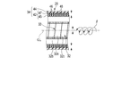
- FIG. 1 is a schematic view showing an endoscope according to the first to third embodiments.
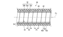
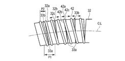
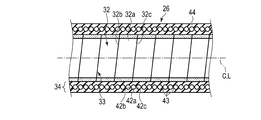
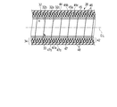
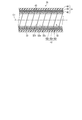
- FIG. 2A is a schematic cross-sectional view along the longitudinal axis of the flexible tube of the insertion portion of the endoscope according to the first embodiment.
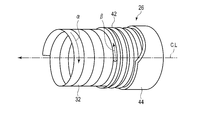
- FIG. 2B is a schematic view showing the structure of the flexible tube of the insertion portion of the endoscope according to the first embodiment.
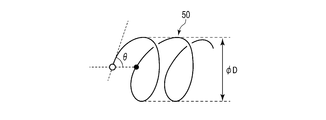
- FIG. 3A is a schematic view showing a part of a suitable coil.
- FIG. 3B is a schematic view showing the relationship among the length, twist angle and diameter of the coil in FIG. 3A.
- FIG. 4 is a schematic diagram showing comparison of the change in outer diameter according to the pitch of a helical tube when helical tubes having different pitches (widths along the longitudinal axis) are respectively extended by the same length along the longitudinal axis.
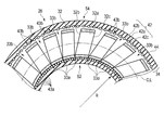
- FIG. FIG. 5 is a schematic view showing the flexible tube shown in FIG. 2A of the insertion portion of the endoscope according to the first embodiment in a bent state.
- FIG. 6 is a flexible tube according to a first modification of the first embodiment, and is a schematic cross section showing a flexible tube in which no close contact portion exists in a second helical tube outside the first helical tube.
- FIG. 7A shows a flexible tube according to a first modification of the first embodiment when the winding direction of the first helical tube and the winding direction of the second helical tube are opposite to each other. It is the schematic which shows the state of a 1st helical tube and a 2nd helical tube when it starts bending from a straight state.
- FIG. 7B illustrates the flexible tube according to the first modification of the first embodiment when the winding direction of the first helical tube and the winding direction of the second helical tube are the same. It is the schematic which shows the state of a 1st helical tube and a 2nd helical tube when it starts bending from a straight state.
- FIG. 7A shows a flexible tube according to a first modification of the first embodiment when the winding direction of the first helical tube and the winding direction of the second helical tube are opposite to each other. It is the schematic which shows the state of a 1st helical tube and a 2nd helical tube when it starts
- FIG. 8A is a schematic cross-sectional view showing a second spiral tube having a contact portion having a shape different from that of the example shown in FIG. 2A in a flexible tube according to a second modification of the first embodiment.
- FIG. 8B is a schematic cross-sectional view showing a second spiral tube having a contact portion having a shape different from the example shown in FIGS. 2A and 8A of the flexible tube according to the second modification of the first embodiment. is there.
- FIG. 8C is a schematic view showing a second spiral tube of a flexible tube according to a second modification of the first embodiment, which has a contact portion having a shape different from the example shown in FIGS. 2A, 8A and 8B.
- FIG. 9 is a flexible tube according to a third modification of the first embodiment, and schematically showing an example in which the first helical tube has a loosely wound portion near the proximal end of the first helical tube.
- FIG. 10 is a flexible tube according to a fourth modification of the first embodiment, schematically showing the flexible tube in a state in which the second helical tube is separated with respect to the inner peripheral surface of the outer shell.
- FIG. FIG. 11 is a flexible tube according to a fifth modification of the first embodiment, in which the second helical tube is embedded between the inner peripheral surface and the outer peripheral surface of the outer shell. It is a schematic sectional view shown.
- FIG. 10 is a flexible tube according to a fourth modification of the first embodiment, schematically showing the flexible tube in a state in which the second helical tube is separated with respect to the inner peripheral surface of the outer shell.
- FIG. 11 is a flexible tube according to a fifth modification of the first embodiment, in which the second helical
- FIG. 12 is a schematic cross-sectional view along the longitudinal axis of the flexible tube of the insertion portion of the endoscope according to the second embodiment.
- FIG. 13A is a schematic view showing a left-handed helical tube forming a part of a flexible tube.
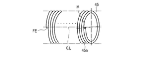
- FIG. 13B shows a left-handed helical tube constituting a part of a flexible tube, and from the state shown in FIG. 13A with one end side (left end in FIG. 13B) of the helical tube fixed. The other end side (right end in FIG. 13B) of the helical tube is rotated in the direction of the arrow ⁇ with respect to the longitudinal axis (central axis) to reduce the diameter of the other end with respect to one end side.
- FIG. 13C shows a left-handed helical tube constituting a part of a flexible tube, and from the state shown in FIG. 13A with one end side (left end in FIG. 13C) of the helical tube fixed.
- the other end side (right end in FIG. 13C) of the helical tube is rotated in the direction of arrow ⁇ with respect to the longitudinal axis (central axis), and the diameter of the other end is increased with respect to one end side.
- FIG. 14A shows that the first helical tube, the inner layer and the outer layer of the second helical tube when the flexible tube according to the second embodiment is rotated in the direction of arrow ⁇ with respect to the longitudinal axis It is a schematic sectional drawing which shows typically the state which diameter-reduces / diameter-expands.
- FIG. 14B shows that when the flexible tube according to the second embodiment is rotated in the direction of arrow ⁇ with respect to the longitudinal axis, the first spiral tube, the inner layer and the outer layer of the second spiral tube are in the radial direction It is a schematic sectional drawing which shows typically the state which diameter-reduces / diameter-expands.
- FIG. 15 is a schematic cross-sectional view along the longitudinal axis of the flexible tube of the insertion portion of the endoscope according to the third embodiment.
- the endoscope 10 has an elongated insertion portion 12 which can be inserted into a hole such as an appropriate body cavity such as a large intestine or an esophagus.
- the insertion portion 12 defines a longitudinal axis L by its distal end and its proximal end.
- the endoscope 10 has an operation unit 14 which is held by the user (operator) at the proximal end of the insertion unit 12 and various operations are performed.
- the operation unit 14 includes an operation unit main body 16 in which the UD knob 16a and the RL knob 16b are disposed, a base end portion of the insertion portion 12 gripped by the user, and a bending stopper 18a (a base of the flexible tube 26 described later And a grip 18 disposed at the end).
- the insertion portion 12 has a distal end portion 22, a bending portion 24, and a flexible tube (flexible tube for endoscope) 26 along the longitudinal axis L from the distal end side toward the proximal end side.
- the distal end portion 22 is the most distal end of the insertion portion 12 and is formed of, for example, a hard material on which the distal end of the illumination optical system, the distal end of the observation optical system, the distal end of the channel (both not shown) and the like are arranged.
- the bending portion 24 can be bent upward and downward by the operation of the UD knob 16 a of the operation portion 14.
- the bending portion 24 can be bent in the right direction and the left direction by the operation of the RL knob 16 b of the operation portion 14.
- the upward and downward directions of the bending portion 24 are, for example, substantially parallel to the vertical direction of the image obtained by the above-described observation optical system.
- the rightward and leftward directions of the bending portion 24 are, for example, substantially parallel to the horizontal direction of the aforementioned image.
- the insertion part 12 demonstrates the example which curves the bending part 24 actively, it may be a structure where a bending part is bent passively by external force.
- the insertion portion 12 may have, as the bending portion 24, an active bending structure and a passively bending structure adjacent along the longitudinal axis L.
- the flexible tube 26 has flexibility and is passively bent by an external force toward the longitudinal axis L.
- the flexible tube (flexible tube portion) 26 has a hollow shape.
- the flexible tube 26 is formed so that the total length along the longitudinal axis L is longer than the distal end portion 22 and the bending portion 24 of the insertion portion 12.
- the flexible tube 26 is provided between the bending portion 24 and the grip portion 18 of the operation portion 14.
- the flexible tube 26 is in a straight straight state (see FIG. 2A) and in a bent state with respect to the straight state (see FIG. 5), ie, a bent state with respect to the linearly extending longitudinal axis L Can be elastically deformed.
- the flexible tube 26 has a first helical tube 32 and an outer layer portion 34 in order from the radially inner side to the outer side.
- the first helical tube 32 is inserted into the outer layer portion 34.
- a common central axis C parallel to the longitudinal axis L is defined in the first helical tube 32 and the outer layer portion 34.
- the central axis C and the longitudinal axis L coincide with each other.
- the outer layer portion 34 has appropriate flexibility.
- the outer layer portion 34, together with the first helical tube 32 can be elastically deformed between a straight state (see FIG. 2A) and a bending state in which the longitudinal axis L (central axis C) is bent (see FIG. 5).
- the outer layer portion 34 has, for example, a coiled second spiral tube 42 and an outer cover 44 made of a resin material coated on the outer peripheral side thereof.
- the second spiral tube 42 and the shell 44 be integrated, such that the second spiral tube 42 is disposed so as to be at least partially embedded in the shell 44.
- the second helical tube 42 is provided between the outer circumferential surface of the outer sheath 44 and the outer circumferential surface of the first helical tube 32.
- the second spiral tube 42 is not exposed to the outer peripheral surface of the flexible tube 26 when the flexible tube 26 is assembled as the endoscope 10.
- the inner circumferential surface of the second helical tube 42 is preferably in contact with the outer circumferential surface of the first helical tube 32. For this reason, the second spiral tube 42 is provided between the inner peripheral surface of the outer cover 44 and the outer peripheral surface of the first spiral tube 32.
- the first helical tube 32 and the outer layer portion 34 are respectively fixed at the distal end and the proximal end of the flexible tube 26, that is, at both ends separated along the longitudinal axis L, in a substantially straight and natural length state.
- Bases 26 a and 26 b are connected to both ends of the flexible tube 26.
- One base (a tip end side base) 26 a is connected to the bending portion 24, and the other base (a base end side base) 26 b is connected to a grip 18 of the operation unit 14.
- One base 26a has a base body (inner base) 27a and a ring-shaped member (outer base) 27b.
- the inner peripheral surface of the mouthpiece main body 27a is connected to the tip of the first helical tube 32, for example, by laser welding.
- the inner peripheral surface of the mouthpiece main body 27a and the tip of the first helical tube 32 may be connected by a general fixing method such as solder, an adhesive, caulking, or the like.
- the tip of the second spiral tube 42 is disposed on the outer peripheral surface of the mouthpiece main body 27a.
- a ring-shaped member 27 b is disposed outside the distal end portion of the second helical tube 42.
- the ring-shaped member 27b crimps the tip of the second spiral tube 42 with the outer peripheral surface of the mouthpiece main body 27a. For this reason, the tip of the second helical tube 42 is connected to the base 26 a.
- the base 26a and the second spiral tube 42 can be connected by an appropriate fixing method in addition to using the ring-shaped member 27b.
- a gap may be formed between the base 26 a and the tip of the outer cover 44.
- a tube (not shown) made of, for example, a rubber material is coated on the outer periphery of the curved portion 24, the cap 26 a and the outer cover 44.
- the other base 26 b has an inner base 28 a and an outer base 28 b.
- the base end of the first helical tube 32 and the base end of the outer layer portion 34 are disposed between the outer peripheral surface of the inner cap 28 a and the inner peripheral surface of the outer cap 28 b.
- the outer mouth ring 28b crimps the base end of the first helical tube 32 and the base end of the outer layer portion 34 with the outer peripheral surface of the inner mouth ring 28a. For this reason, the proximal end of the first helical tube 32 and the proximal end of the outer layer portion 34 are connected to the base 26 b.
- the base end of the first helical tube 32 and the base end of the outer layer portion 34 may be connected to the base 26 b by any other appropriate fixing method.
- the first helical tube 32 and the outer layer portion 34 are fixed only at both ends by the caps 26a and 26b.
- the first helical tube 32 and the outer layer portion 34 Control the difference in elongation between the
- the caps 26a and 26b are used to form the first helical tube 32, the second helical tube 42 and the shell 44. Stretch by the same length.
- the mouthpieces 26a and 26b cause the first helical tube 32, the second helical tube 42, and the shell 44 to shrink by the same length. That is, the amounts of expansion and contraction of the first helical tube 32, the second helical tube 42, and the shell 44 are prevented from being different from one another.
- the first helical tube 32, the second helical tube 42 and the outer shell 44 are on the longitudinal axis L (central axis C). The lengths along will be approximately the same. That is, the overall lengths of the first helical tube 32 and the outer layer portion 34 along the longitudinal axis L substantially coincide with each other.
- the first helical tube 32 is formed by spirally winding a first wire (wire) 32a.
- the first wire 32a is formed in a plate shape, for example, a plate shape formed of a metal material such as stainless steel, etc., as an example.
- the plate width of the first strand 32a is preferably constant from one end to the other end, and is different depending on the type (outside diameter and bending ease) of the endoscope 10 according to the insertion target. Absent.
- the plate width of the first wire 32a is, for example, about 2 mm to 4 mm.
- the thickness of the first strand 32a is preferably constant from one end to the other end, and is not limited to the same.
- the plate thickness of the first wire 32a is, for example, about 0.3 mm to 0.5 mm.
- the first spiral tube 32 has a close contact portion (first close contact portion) 33 in which adjacent portions (edges) 32b and 32c of the first strands 32a are in close contact with each other along the longitudinal axis L. For this reason, in the first spiral tube 32, the close contact portion 33 is formed between the adjacent portions 32b and 32c of the first strand 32a. In particular, in the present embodiment, in the first helical tube 32, one close contact portion 33 is continuously formed over the entire length between one end and the other end. The close contact portion 33 is wound in close contact with each other with an initial tension (preload) in a direction in which adjacent portions 32b and 32c of the first strands 32a mutually compress along the longitudinal axis L.
- first close contact portion 33 in which adjacent portions (edges) 32b and 32c of the first strands 32a are in close contact with each other along the longitudinal axis L.
- the inner diameter and the outer diameter of the first helical tube 32 are preferably substantially constant.
- the inner diameter of the first helical tube 32 at this time is, for example, about 9 mm to 12 mm.
- One of the adjacent portions 32b and 32c of the first strand 32a is the distal end portion 32b directed to the distal end side, and the other is the proximal end portion 32c directed to the proximal end side.
- the second helical tube (coil) 42 of the outer layer portion 34 is formed by spirally winding a second wire 42 a formed of, for example, a metal material such as stainless steel.
- the second strand 42 a of the second helical tube 42 has a smaller dimension (width) in the direction along the longitudinal axis L than the first strand 32 a of the first helical tube 32.
- the cross-sectional shape of the second wire 42a of the second helical tube 42 is not limited.
- the cross-sectional shape of the second wire 42a is, for example, circular.
- the second wire 42a preferably has a diameter twice to five times that of a wire used for a blade (reticular tube) of a flexible tube of a general endoscope, for example.
- the diameter of the second wire 42a is not limited.
- the diameter of the second wire 42a is, for example, about 0.4 mm to 0.5 mm.
- the 2nd spiral pipe 42 is also wound in the state where it has initial tension and was in close contact like the 1st spiral pipe 32. That is, the second helical tube 42 is a close contact portion (second close contact) in which the second strands 42 a are spirally wound and the adjacent portions (edges) 42 b and 42 c are in close contact with each other along the longitudinal axis L Part) 43 is included. For this reason, in the second spiral tube 42, the adhesion portion 43 is formed between the adjacent portions 42b and 42c of the second wire 42a.
- one close contact portion 43 is continuously formed over the entire length between the one end and the other end of the second spiral tube 42.
- the intimate contact portion 43 is wound in close contact with an initial tension (preload) in a direction in which the adjacent portions 42b and 42c of the second strand 42a mutually compress along the longitudinal axis L. For this reason, adjacent parts 42b and 42c of the 2nd strand 42a mutually push along the longitudinal axis L mutually.
- the inner diameter of the second helical tube 42 at this time is not limited because it varies depending on the type of endoscope 10 (diameter or easiness of bending) according to the insertion target.
- the inner diameter and the outer diameter of the second helical tube 42 are substantially constant.
- the inner diameter of the second helical tube 42 is, for example, about 9 mm to 12 mm.
- One of the adjacent portions 42b and 42c of the second strand 42a is the distal end side portion 42b directed to the distal end side, and the other is the proximal end side portion 42c directed to the proximal end side.
- the second wire 42a whose width is narrower along the longitudinal axis L than the first wire 32a is longer than the first spiral tube 32 in the unit length than the first spiral tube 32. It is spirally wound and formed so that the number of turns per winding increases. For this reason, the pitch P2 of the second helical tube 42 is smaller than the pitch P1 of the first helical tube 32.
- the winding direction of the second helical tube 42 is preferably opposite to the winding direction of the first helical tube 32.
- the winding direction ⁇ of the first helical tube 32 is right-handed (clockwise from the beginning of winding (end)), and the winding direction ⁇ of the second helical tube 42 is Left-handed (counterclockwise from the beginning of winding (end)).
- the outer diameter of the flexible tube 26 may be smaller.
- the outer diameter of the first helical tube 32 and the second helical tube 42 The inner diameter is the same size.
- the friction between the outer peripheral surface of the first helical tube 32 and the inner peripheral surface of the second helical tube 42 is preferably kept as low as possible, regardless of the presence or absence of the clearance.
- the outer sheath 44 coated on the second helical tube 42 is formed of a resin material having elasticity and flexibility.
- the shell 44 has a longitudinal axis L (central axis C) bent along with the first helical tube 32 and the second helical tube 42.
- the outer cover 44 according to the present embodiment is formed so as to be easily extended along the longitudinal axis L, and formed in the radial direction of the flexible tube 26 orthogonal to the longitudinal axis L so as to be more difficult to expand and contract than the direction along the longitudinal axis L ing. Therefore, when the user holds the proper position of the outer cover 44 and twists around the longitudinal axis L, the twisting force is favorably transmitted from the proximal end side to the distal end side of the outer cover 44.
- the thickness of the outer cover 44 is, for example, about 0.3 mm. Then, the outer diameter of the outer cover 44, that is, the outer diameter of the flexible tube 26 is set appropriately without being limited in specific dimensions, such as about 12 mm to 14 mm, for example. It is preferable that the outer cover 44 having an outer diameter of about 13 mm can extend along the longitudinal axis L by about 20% of the entire length of the outer cover 44 as an example.
- resin is used as the material of the outer cover 44.
- the material of the resin of the outer cover 44 is not particularly limited.
- polyurethane, polyester, polyether or the like is used for the shell 44.
- the compounding ratio of these resins is changed from the distal end side of the flexible tube 26 toward the proximal end side. For this reason, the bending easiness / the bending difficulty of the shell 44 changes from the distal end side to the proximal end side. It is preferable that the front end side of the outer cover 44 is soft and bendable, and the rear end side is harder and more difficult to bend.
- the bendability / bending difficulty between the tip and the base in the outer cover 44 does not gradually change, and even if the bendability / bending difficulty is constant for an appropriate length Good.
- the bending easiness / the bending difficulty of the flexible pipe 26 is the outer shell 44. Adjusted by the easiness of bending / difficulty of bending.
- the bending easiness / the bending difficulty of the flexible tube 26 is adjusted so that bending on the rear end side is more difficult than on the front end side.
- the material a fluorine tube, a rubber tube, etc. which can be expanded-contracted along the longitudinal axis L is also used for these built-in things.
- the outer diameter of the coil 50 in the state before stretching is D
- the twist angle per turn is ⁇
- the length of the coil 50 per turn is Lo.
- the first helical tube 32 and the second helical tube 42 shown in FIG. 4 have outer diameters D at their natural lengths before extension.
- the first helical tube 32 has a pitch P1 larger than the pitch P2 of the second helical tube 42.
- the second helical tube 42 has a pitch P2 smaller than the pitch P1 of the first helical tube 32.
- the length L1 of the first helical tube 32 and the second helical tube 42 in their natural length along, for example, the longitudinal axis L before extension is extended to a length L2.
- the outer diameter of the first helical tube 32 is from D to d1 ( ⁇ d2 ⁇ D)
- the outer diameter of the second helical tube 42 is from D to d2 ( ⁇ D).
- the variation (D-d1) of the diameter (outer diameter) of the first helical tube 32 is larger than the variation (D-d2) of the diameter (outer diameter) of the second helical tube 42. Therefore, the amount of diameter reduction of the second helical tube 42 is smaller than that of the first helical tube 32 when the same amount of elongation occurs in a certain state such as the natural length.
- the user holds the appropriate position of the flexible tube 26 of the insertion portion 12 of the endoscope 10 with, for example, the right hand, and inserts the distal end portion 22 into the intestinal tract along the longitudinal axis L of the flexible tube 26 I will put it.
- the user pushes the distal end portion 22 toward the back side of the intestinal tract along the longitudinal axis L and inserts the distal end portion 22 toward the back side of the intestinal tract while twisting the flexible tube 26 Go.
- the first helical tube 32 is wound over the entire length such that adjacent portions 32b and 32c of the first strands 32a are in close contact with each other with initial tension. For this reason, in the first spiral tube 32, the spiral close contact portion 33 is continuously formed from one end of the second spiral tube 42 to the other end. Further, in the present embodiment, the second helical tube 42 is wound in the state where the adjacent portions 42b and 42c of the second strands 42a are in close contact with each other with initial tension over the entire length. For this reason, in the second spiral tube 42, the intimate contact portion 43 is continuously formed from one end of the second spiral tube 42 to the other end. Therefore, the flexible tube 26 can exhibit high elasticity by the contact portions 33 and 43 over the entire length.
- “elastic” means “easiness of return” that the flexible tube 26 returns from the bent state to the original shape (linear state).
- the adhesion strength of the adhesion parts 33 and 43 may have an unintended appropriate variation.
- the variation in the adhesion strength of the adhesion parts 33 and 43 of the first spiral pipe 32 and the second spiral pipe 42 is smaller than the adhesion strength.
- the first helical tube 32 and the second helical tube 42 there is no place where bending ease / bending difficulty changes rapidly along the longitudinal axis L. Therefore, for example, when inserting the insertion portion 12 into the intestinal tract such as the large intestine, the flexible tube 26 is prevented from bending suddenly unintentionally with respect to the insertion target.
- the flexible tube 26 is deformed from the straight state (see FIG. 2A) to the bending state (see FIG. 5) by the load of an appropriate external force in the direction from the radially outward direction toward the longitudinal axis L. At this time, since the flexible tube 26 has an appropriate length, it does not have to be influenced and bent by the external force over the entire length. For example, the flexible tube 26 may only be bent at the position where the external force is received and in the vicinity thereof.
- the first helical tube 32 when the first helical tube 32 is bent from the straight state to the bending state, the first helical tube 32 is adjacent to the first strands 32 a of the first helical tube 32.
- a contact portion 33a maintaining contact between the portions 32b and 32c and a spaced apart portion 33b are formed.
- the second spiral tube 42 when the second spiral tube 42 is bent from the straight state to the bent state, the second spiral tube 42 is a part of the adjacent portions 42 b and 42 c of the second strands 42 a of the second spiral tube 42.
- a contact portion 43a maintaining contact therebetween and a spaced apart portion 43b are formed.
- the inner circumferential side portion 52 of the flexible tube 26 is formed by the plurality of contact portions 33a and 43a, and the plurality of spaced portions 33b , 43b form the outer peripheral portion 54 of the flexible tube 26.
- the inner circumferential portion 52 and the outer circumferential portion 54 are formed by the outer shell 44, the second helical tube 42 and the first helical tube 32, respectively.
- the outer peripheral side portion 54 is on the opposite side of the inner peripheral side portion 52 across the longitudinal axis L.
- bending radius R is prescribed
- the lengths of the inner circumferential side portions 52 of the first helical tube 32 and the second helical tube 42 are It does not change. For this reason, the length of the inner circumferential side portion 52 of the flexible tube 26 is maintained between the straight state and the bent state, and is not stretched or contracted.
- the inner circumferential portion 52 of the flexible tube 26 can be a neutral plane with no or almost no variation in length along the longitudinal axis L in the straight and bent states.
- the length along the longitudinal axis L of the first helical tube 32 and the outer layer portion 34 in the bent state with respect to the length along the longitudinal axis L of the first helical tube 32 and the outer layer portion 34 in the linear state Is stretched. Therefore, the length along the longitudinal axis L is longer than the length of the inner circumferential portion 52.
- the length of the outer circumferential side portion 54 opposite to the inner circumferential side portion 52 across the longitudinal axis L Is longer than the length along the longitudinal axis L. Therefore, the length along the longitudinal axis L of the flexible tube 26 and the length of the outer peripheral side portion 54 are elongated relative to the straight state when in the bent state.
- the first helical tube 32 and the second helical tube 42 are in a straight state. Each diameter shrinks. At this time, the pitch P2 of the second helical tube 42 is smaller than the pitch P1 of the first helical tube 32. For this reason, the inner first spiral tube 32 of the flexible tubes 26 has a larger diameter than the outer second spiral tube 42 of the flexible tubes 26. Therefore, even if there is no clearance between the first helical tube 32 and the second helical tube 42 in the straight state, the outer circumferential surface of the first helical tube 32 and the second helix are deformed when bent into a bent state.
- a clearance is generated between the inner circumferential surface of the tube 42, that is, the inner circumferential surface of the outer layer portion 34. For this reason, the interference between the first helical tube 32 and the second helical tube 42 when reaching from the straight state to the bending state is suppressed.
- the first helical tube 32 and the second helical tube 42 are bent while extending along the longitudinal axis L. That is, the flexible tube 26 is bent while extending along the longitudinal axis L with respect to the straight state.
- the flexible tube 26 has the adjacent portions 32b and 32c of the first strands 32a of the first helical tube 32 and the second strands 42a of the second helical tube 42. Adjacent portions 42b and 42c are in close contact over the entire length.
- the flexible tube 26 can allow the shell 44 to extend properly and bend to the minimum radius required for the endoscope 10.
- the length along the longitudinal axis L of the flexible tube 26 is It extends about 12.5% of the total length of the flexible tube 26.
- the second helical tube 42 of the outer layer portion 34 is not braided, only the second wire 42a is formed in a helical shape. For this reason, the second wire 42a of the second helical tube 42 is not undulated like a blade.
- the second strands 42a of the second helical tube 42 are larger in diameter and higher in rigidity than the strands forming the blade even if they are the same material. Therefore, when the flexible tube 26 is in a bent state, the second helical tube 42 has sufficient rigidity in the radial direction, and can endure the force to collapse in the radial direction.
- the outer shell 44 of the outer layer portion 34 covers the second helical tube 42, it moves in conjunction with the movement of the second helical tube 42.
- the outer layer portion 34 is difficult to flatten when it is bent.
- the first helical tube 32 has sufficient rigidity in the radial direction, and can withstand the force to collapse in the radial direction. For this reason, the first helical tube 32 is difficult to flatten when it is bent. Therefore, the first helical tube 32 and the outer layer portion 34 do not easily interfere with each other, and the flexible tube 26 is bent smoothly.
- the adhesion portions 33 and 43 are continuous from one end of the flexible tube 26 to the other end.
- the outer skin 44 also extends along the longitudinal axis L in conjunction with the extension along the longitudinal axis L of the first helical tube 32 and the second helical tube 42. For this reason, even if the flexible tube 26 is bent, the relative movement of the first helical tube 32, the second helical tube 42 and the envelope 44 along the longitudinal axis L inside the envelope 44 is suppressed. There is. That is, the amount of relative movement of the first helical tube 32, the second helical tube 42, and the shell 44 is small.
- the second helical tube 42 when the second helical tube 42 is in a straight state along the longitudinal axis L and in a bent state, a part of the second strand 42 a is formed on the outer peripheral surface of the first helical tube 32. I am always in touch. Thus, even if there is no clearance between the first helical tube 32 and the outer layer portion 34, the interference between the first helical tube 32 and the outer layer portion 34 is suppressed, and the flexible tube 26 smoothly. Be bent.
- the flexible tube 26 is brought from a straight state to a bent state by an external force. Therefore, for example, when the distal end portion 22 of the insertion portion 12 is inserted into the intestine such as a region from the anus to the deep part of the large intestine, the flexible tube 26 is bent, for example, from the inner circumferential surface of the intestine. It is bent by the addition of an external force exceeding the difficulty. For this reason, the flexible tube 26 of the insertion portion 12 is bent along the bending of the intestine having flexibility such as the large intestine.
- the first spiral tube 32 has a close contact portion 33 continuously formed over the entire length between one end and the other end. Further, in the second helical tube 42, the close contact portion 43 is continuously formed over the entire length between one end and the other end. For this reason, when the external force applied to the flexible tube 26 is removed or reduced, the adjacent portions 32b and 32c of the first strands 32a try to be in close contact with each other, and the second strands 42a are adjacent to each other. The parts 42b and 42c try to be in close contact with each other. Therefore, with the contact portions 33a and 43a of the first helical tube 32 and the second helical tube 42 in FIG.
- the separated portions 33b and 43b of the first helical tube 32 and the second helical tube 42 are It will be smaller and smaller. Further, the total length along the longitudinal axis L of the outer cover 44 also becomes shorter as the separated portions 33 b and 43 b of the first helical tube 32 and the second helical tube 42 become smaller and smaller. That is, the length of the outer peripheral portion 54 of the flexible tube 26 and the length along the longitudinal axis L are brought close to the length of the inner peripheral portion 52 of the flexible tube 26.
- the straight state from the bent state Will be returned to
- an adhesive force is applied to the intimate contact portions 33 and 43 continuously from the tip end to the base end.
- the first helical tube 32 and the second helical tube 42 try to make the flexible tube 26 in a straight straight state, and improve the operability when straightening an intestinal tract such as a large intestine, for example.
- the shell 44 exerts an appropriate elastic force.
- the flexible tube 26 according to the present embodiment extends at a position along the longitudinal axis L in the bent state more than in the straight state. Therefore, even if the outer sheath 44 of the flexible tube 26 according to the present embodiment is in the same bending state, the total amount of extension of the outer circumferential side portion 54 is greater than when the position along the longitudinal axis L of the outer sheath 44 does not extend. growing. And the length of the position in alignment with longitudinal axis L becomes short, when outer skin 44 of flexible tube 26 concerning this embodiment is a straight state rather than a bent state. For this reason, as the extension length of the outer shell 44 when the bending state is reached from the straight state becomes longer, the reaction force to return to the original length becomes larger. Therefore, the flexible tube 26 according to the present embodiment exhibits higher elasticity (reaction force) as compared with the case where the position along the longitudinal axis L does not extend.
- the flexible tube 26 is easy to return the bent state to the straight state due to its elasticity. For this reason, the flexible tube 26 arranges the bent portion of the intestinal tract into a substantially linear shape by utilizing the elasticity of the flexible tube 26 after, for example, the bending portion 24 exceeds the appropriate bending position of the intestinal tract. For this reason, for example, an intestinal tract having a small bending radius, such as a sigmoid colon, is trimmed in a substantially linear manner.
- the substantially straight flexible tube 26 is easily advanced to the substantially straight intestinal tract. Therefore, the user can insert the distal end portion 22 of the insertion portion 12 into the deep portion of the intestinal tract.
- the clearance between the outer circumferential surface of the first helical tube 32 and the inner circumferential surface of the second helical tube 42, that is, the inner circumferential surface of the outer layer portion 34 gradually decreases as the bending state is returned to the linear state. .
- the flexible tube 26 of the insertion portion 12 is appropriately bent according to the external force applied from the inner circumferential surface of the intestinal tract, and the elasticity of the flexible tube 26 makes the intestinal tract approximately straight.
- the tip 22 of the insertion portion 12 is moved to the back side of the intestinal tract while repeating.
- the first helical tube 32 reduces its diameter when the entire length thereof extends along the longitudinal axis L.
- the second helical tube 42 reduces its diameter when its entire length extends along the longitudinal axis L.
- the inner first helical tube 32 is the outer layer portion 34 (the outer second helical tube 42).
- the amount of diameter reduction is larger than that. Therefore, when the flexible tube 26 is bent and when the bent flexible tube is straightened, no clearance is provided between the first helical tube 32 and the outer layer portion 34 in the flexible tube 26. Also, the interference between the first helical tube 32 and the outer layer portion 34 can be suppressed. Therefore, the flexible tube 26 can be smoothly bent, and the outer diameter of the flexible tube 26 can be kept small, and for example, a state in which the burden on the patient is small can be maintained.
- the first spiral tube 32 has a close contact portion 33 continuously formed over the entire length between one end and the other end. For this reason, in the first helical tube 32, there is no region where the rapid bendability / bending difficulty changes along the longitudinal axis L. Therefore, when the user holds the proximal end side of the flexible tube 26 and pushes the distal end portion 22 of the insertion portion 12 into the lumen, that is, toward the far side of the intestinal tract, the first helical tube 32 It is easy to transmit pushing force applied to the spiral tube 32 toward the tip side.
- the flexible tube 26 is less likely to cause buckling or unintentional deflection, and the force is reliably transmitted to the distal end portion 22 Be done.
- the second wire 42 a of the second helical tube 42 is spirally wound on the outside of the close contact portion 33 so that the number of turns is larger than that of the first helical tube 32. For this reason, the flexible tube 26 can be bent into a smooth shape when it is bent, and can exhibit elasticity to improve the insertability into the lumen (intestinal tract) over the entire length.
- the flexible tube for an endoscope having good elasticity while suppressing the interference between the first helical tube 32 and the outer layer portion 34 outside the first helical tube 32. 26 and the endoscope 10 can be provided.
- the second spiral tube 42 has the close contact portion 43 continuously formed over the entire length between one end and the other end. For this reason, in the second helical tube 42, there is no region where the rapid bendability / bending difficulty changes along the longitudinal axis L.
- the second helical tube 42 The push-in force can be easily transmitted toward the tip side in cooperation with the spiral tube 32 of 1.
- the first spiral tube 32 has the close contact portion 33 continuously formed over the entire length between one end and the other end, so that the first spiral tube 32 can be processed uniformly over the entire length. For this reason, the first helical tube 32 according to the present embodiment is easy to process, and can be processed at a lower cost than in the case where the loosely wound portion is included. Also, the second helical tube 42 can be processed uniformly as well as the first helical tube 32. For this reason, the second helical tube 42 is easy to process, and can be processed at a lower cost than in the case where the loosely wound portion is included.
- the built-in thing inside the 1st spiral tube 32 of the flexible tube 26 is using the raw material which can be expanded-contracted.
- the flexible tube 26 can expand and contract along with the expansion and contraction along the longitudinal axis L. Therefore, when the flexible tube 26 is appropriately deformed between the straight state and the bent state, the relative moving amount between the flexible tube 26 and the internal component can be reduced, and the first spiral It is possible to prevent the inner peripheral surface of the tube 32 and the internal components from rubbing against or being caught.
- the second spiral tube 42 shown in FIG. 6 does not have the close contact portion 43. That is, the distal end side portion 42b and the proximal end side portion 42c of the second strand 42a of the second helical tube 42 are formed as loose windings separated from each other. The distal end side portion 42 b and the proximal end side portion 42 c may simply be in contact with each other in a state where the adhesion is not applied. At this time, the condition that the second helical pipe 42 pitch P2 is smaller than the pitch P1 of the first helical pipe 32 may be satisfied. And, in this modification, a part of the second spiral tube 42 is embedded in the inner circumferential surface of the outer cover 44. On the other hand, the inner circumferential surface of the second helical tube 42 is in contact with or can be brought into contact with the outer circumferential surface of the first helical tube 32.
- the first spiral tube 32 has the close contact portion 33.
- the entire length of the inner peripheral portion (the portion indicated by reference numeral 52 in FIG. 5) of the second helical tube 42 is restricted by the contact portion 33a of the first helical tube 32. It does not shrink.
- the first helical tube 32 and the second helical tube 42 extend along the longitudinal axis L. Therefore, the first helical tube 32 and the outer layer portion 34 extend along the longitudinal axis L, and the flexible tube 26 is bent, as in the case where the second helical tube 42 has the adhesion portion 43.
- the adjacent portions 32b and 32c of the first strands 32a are in close contact with each other as in the first embodiment. Do. Therefore, with the first spiral tube 32 contact portion 33a in FIG. 5 as a fulcrum, the separated portion 33b of the first spiral tube 32 becomes gradually smaller. Further, the total length of the outer cover 44 also becomes shorter as the separated portion 33b of the first helical tube 32 becomes smaller and smaller. Therefore, the longitudinal axis L along the first helical tube 32, the second helical tube 42, and the shell 44 is returned from the bent state to the straight state while being contracted toward the original state.
- the first helical tube 32 attempts to bring the flexible tube 26 into a straight straight state, and improves operability in the case of straightening a lumen such as the large intestine, for example.
- FIG. 7A shows an example in which the first helical tube 32 is in the winding direction ⁇ , and the second helical tube 42 is in the winding direction ⁇ opposite to the winding direction ⁇ .
- FIG. 7B shows an example in which the first helical tube 32 is in the winding direction ⁇ , and the second helical tube 42 is in the same winding direction ⁇ as the winding direction ⁇ of the first helical tube 32.
- the winding direction ⁇ of the first helical tube 32 and the winding direction ⁇ of the second helical tube 42 may be the same as or different from each other in the twisting angle ⁇ (see FIG. 3A).
- the flexible tube 26 in the example shown in FIGS. 7A and 7B omits the illustration of the outer cover 44, and the second spiral tube 42 does not have the close contact portion 43 in any case.
- the second helix is more than the pitch P1 of the first helical tube 32.
- the pitch P2 of the tubes 42 is smaller.
- the position where the outer peripheral surface of the wire 32a does not exist may arise inside the wire 42a. Therefore, the second spiral tube 42 may try to enter between the separated portions 33 b of the first spiral tube 32.
- the winding directions of the first helical tube 32 and the second helical tube 42 are the same, the first helical tube 32 and the second helical tube 42 may be caught.
- the winding directions of the first helical tube 32 and the second helical tube 42 according to the present embodiment may be the same, it is preferable to be opposite.
- the cross section of the second wire 42a of the second helical tube 42 is formed in a rectangular shape.
- the second wire 42a moves along the winding direction indicated by the arrow ⁇ in FIG. 2B when the length of the second helical tube 42 along the longitudinal axis L changes, and the second wire 42a Adjacent portions 42b, 42c of can be contacted and separated along the longitudinal axis L.
- the distal end side portion 42b of the second strand 42a of the second helical tube 42 is formed in a convex shape, and the proximal end portion 42c is formed in a concave shape. Therefore, the distal end side portion 42 b and the proximal end side portion 42 c are fitted. Therefore, axial deviation of the distal end side portion 42b and the proximal end side portion 42c of the second strand 42a of the second helical tube 42 in the radial direction of the longitudinal axis L is prevented.
- the tip end portion 42b is appropriately pointed. It is preferable that the proximal end portion 42c has a smaller contact area with respect to the distal end portion 42b, and is formed in a state where friction is not generated as much as possible.
- the distal end side portion 42b of the second strand 42a of the second helical tube 42 is formed in a convex shape, and the proximal end portion 42c is formed in a concave shape. There is.
- the distal end portion 42 b and the proximal end portion 42 c are fitted. For this reason, axial deviation of the distal end side portion 42b and the proximal end side portion 42c of the second strand 42a of the second helical tube 42 in the radial direction of the longitudinal axis L is prevented.
- the distal end side portion 42 b is formed as an appropriate curved surface. It is preferable that the proximal end portion 42c has a smaller contact area with respect to the distal end portion 42b, and is formed in a state where friction is not generated as much as possible.
- the cross section of the second wire 42a of the second helical tube 42 is appropriately formed.
- the first helical tube 32 shown in FIG. 9 has a loosely wound portion 35 at a part between one end and the other end.
- adherence part 33 is not necessarily formed in the 1st spiral tube 32 continuously from one end to the other end.
- the loosely wound portion 35 is preferably formed, for example, in the vicinity of the base end side cap 26 b of the flexible tube 26 in the first spiral tube 32.
- the position of the loosely wound portion 35 is disposed, for example, on the inner side of the folding stop 18a or at a position close to the folding stop 18a.
- the user usually grips the position of the flexible tube 26 closer to the tip 22 than the portion where the loosely wound portion 35 is formed. For this reason, the transferability of the force from the user to the tip 22 is maintained as in the example described in the first embodiment, and hardly changes.
- the second spiral tube 42 and the shell 44 of the outer layer portion 34 have been described as being integrated.
- the second spiral tube 42 and the shell 44 of the outer layer portion 34 are separated.
- the second spiral tube 42 is provided between the inner peripheral surface of the outer cover 44 and the outer peripheral surface of the first spiral tube 32.
- the second strand 42 a of the second helical tube 42 whose width is narrower along the longitudinal axis L than the first strand 32 a of the first helical tube 32 is a first helix outside the contact portion 43. It is spirally wound and formed so that the number of turns is larger than that of the tube 32. Therefore, as in the first embodiment described above, it is possible to provide the flexible tube 26 having good elasticity while suppressing the interference between the first spiral tube 32 and the outer layer portion 34.
- FIG. 11 shows an example in which the second spiral tube 42 of the outer layer portion 34 is embedded in the outer cover 44 so as to be completely and completely enclosed.
- the second spiral tube 42 is provided between the shell 44 and the first spiral tube 32. Even if the flexible tube 26 in this case is bent, the diameter reduction and the diameter increase of the second spiral tube 42 are restricted by the outer cover 44. For this reason, it is harder to bend than the flexible tube 26 described in the first embodiment including each modification.
- the second helical tube 42 may be completely enclosed in the outer shell 44 only for an appropriate length of the flexible tube 26 or over the entire length.
- FIGS. 12 to 14B This embodiment is a modification of the first embodiment including each modification, and the same members as the members described in the first embodiment or members having the same functions are denoted by the same reference numerals as much as possible. I omit explanation.
- the second spiral tube 42 is formed in multiple layers.
- the second helical tube 42 is here formed in two layers and has an inner layer 45 and an outer layer 47.
- the wire 45a of the inner layer 45 has a distal end portion 45b directed to the distal end side and a proximal end portion 45c directed to the proximal end side.
- the strand 47a of the outer layer 47 has a distal end portion 47b directed to the distal end side and a proximal end portion 47c directed to the proximal end side.
- the pitch of the inner layer 45 and the outer layer 47 is preferably the same or smaller in the outer layer 47. Therefore, in the inner layer 45 and the outer layer 47, the amount of diameter reduction when the same amount of elongation occurs is the same or smaller in the outer layer 47.
- the winding direction ⁇ of the strands 45 a of the inner layer 45 is opposite to the winding direction ⁇ of the first helical tube 32.
- the winding direction ⁇ of the strands 47 a of the outer layer 47 is opposite to the winding direction ⁇ of the inner layer 45. That is, the winding direction ⁇ of the outer layer 47 is the same as the winding direction ⁇ of the first helical tube 32.
- the inner layer 45 has the contact portion 46 continuously formed over the entire length between one end and the other end.
- the close contact portion 46 is wound in close contact with each other with an initial tension (preload) in a direction in which the adjacent portions 45 b and 45 c of the inner layer 45 mutually compress along the longitudinal axis L.
- the outer layer 47 preferably has the contact portion 48 formed continuously over the entire length between one end and the other end.
- the adhesion portion 48 is wound in close contact with an initial tension (preload) in a direction in which the adjacent portions 47 b and 47 c of the outer layer 47 mutually compress along the longitudinal axis L.
- the inner wire (second wire) 45a of the inner layer 45 may be formed as a loose winding.
- the outer strands (second strands) 47a of the outer layer 47 may be formed as a loose winding.
- the first strand 32a of the first helical tube 32 is right-handed, and the inner strand (second strand) 45a of the inner layer 45 of the second helical tube 42 is left-handed, and the second helical tube 42 is It is assumed that the outer strand (third strand) 47a of the outer layer 47 is right-handed.
- the inner strand 45a of the inner layer 45 is, for example, left-handed
- one end side (for example, the tip end side) of the inner layer 45 is fixed at a position indicated by a symbol FE Suppress the rotation of
- FIG. 13B when the position indicated by the symbol M on the other end side of the inner layer 45 is twisted so as to move in the direction of the arrow ⁇ (right direction),
- the diameter is smaller than in the normal state shown in FIG. 13A.
- the diameter hardly changes from the normal state.
- the position indicated by the symbol M on the other end side of the inner layer 45 is moved in the direction of the arrow ⁇ (left direction) as shown in FIG. 13C from the normal state shown in FIG. 13A, the inner layer At the other end of 45, the diameter is larger than in the normal state shown in FIG. 13A. Since one end side of the inner layer 45 is fixed, the diameter hardly changes from the normal state.
- the first wire 32a of the first helical tube 32 and the second wire 42a of the second helical tube 42 are right-handed.
- the first spiral tube 32 and the second spiral tube 42 are in the normal state (in the state where no external force other than gravity is applied), the first spiral One end side of each of the pipe 32 and the second spiral pipe 42 is fixed or the like to suppress rotation of the one end side.
- the position indicated by the symbol M of the first helical tube 32 and the second helical tube 42 is twisted so as to move in the direction of the arrow ⁇ , the first helical tube 32 and the second helical tube 42 The other end of each has a larger diameter than in the normal state.
- the left side in FIGS. 14A and 14B is the distal end side of the flexible tube 26, and the left side is the proximal end side of the flexible tube 26.
- the flexible tube 26 interferes with the first helical tube 32 and the inner layer 45 of the second helical tube 42, there is no play in twisting of the flexible tube 26. Therefore, when the flexible tube 26 is further twisted from the time point when the first helical tube 32 and the inner layer 45 of the second helical tube 42 interfere with each other, the twist angle of the portion held by the user is substantially the flexible tube It becomes the twist angle of the tip of 26.
- the flexible tube 26 interferes with the inner layer 45 and the outer layer 47 of the second helical tube 42, there is no play in twisting of the flexible tube 26. Therefore, when the flexible tube 26 is further twisted from the time when the inner layer 45 and the outer layer 47 of the second helical tube 42 interfere with each other, the twist angle of the portion held by the user is substantially the tip of the flexible tube 26 It becomes the twist angle of the part.
- the inside of the outer shell 44 is laminated in three layers by the first spiral tube 32 and the inner layer 45 and the outer layer 47 of the second spiral tube 42. Also, as described in the first embodiment, both ends of the flexible tube 26 are fixed to, for example, the caps 26a and 26b.
- the clearance between the outer peripheral surface of the first helical tube 32 and the inner peripheral surface of the inner layer 45 of the second helical tube 42, the outer peripheral surface of the inner layer 45 of the second helical tube 42 and the outer layer 47 The clearance with the inner circumferential surface may or may not be present as described in the first embodiment.
- the inside of the outer cover 44 is stacked in three layers.
- the flexible tube 26 can improve the twist resistance of the flexible tube 26 more than the case where the inside of the outer cover 44 is one layer or two layers, and can extend the product life.
- the flexible tube 26 according to the present embodiment includes the clearance between the outer circumferential surface of the first helical tube 32 and the inner circumferential surface of the inner layer 45 of the second helical tube 42 and the second helical tube 42. By adjusting the clearance between the outer peripheral surface of the inner layer 45 and the inner peripheral surface of the outer layer 47, the twisting force of the flexible tube 26 can be easily transmitted to the tip of the flexible tube 26. For this reason, by using the flexible tube 26 according to the present embodiment, the insertability of the insertion portion 12 into the body cavity can be improved.
- the dimensional relationship between the second helical tube 42 and the first helical tube 32 is such that the inner diameter of the second helical tube 42 is slightly larger than the outer diameter of the first helical tube 32, and there is a small gap.
- the second helical tube 42 and the first helical tube 32 may be in a "tight fit" relationship.
- the strands 45a of the inner layer 45 and the strands 47a of the outer layer 47 that constitute the second spiral tube 42 may be formed by combining materials having the same material, sectional shape, etc. It may be formed by combining different cross-sectional shapes and the like.
- the second spiral tube 42 is not limited to a double layer, and may be configured by winding a wire in three or more double layers as needed.
- FIG. 1 is a modification of the first embodiment and the second embodiment including each modification, and the same members as the members described in the first embodiment and the second embodiment or members having the same functions are provided. The same symbol is attached as much as possible, and the detailed description is omitted.
- a blade (mesh tube) 49 is disposed on the outer periphery of the second spiral tube 42.
- the blade 49 is formed in a cylindrical shape by, for example, knitting a thin metal wire made of stainless steel or the like into a fiber shape.
- the outer layer portion 34 is formed by the second spiral tube 42, the blade 49 and the outer shell 44.
- a second helical tube 42 is wound inside the blade 49, and the blade 49 is covered with an outer shell 44. That is, the second helical tube 42 is different from the blade 49.
- a clearance may be formed between the second helical tube 42 and the blade 49.
- the blade 49 tends to collapse radially.
- the second strands 42a of the second helical tube 42 inside the blade 49 have sufficient rigidity in the radial direction with respect to the blade. Therefore, even if the flexible tube 26 is bent and the blade 49 is crushed in the radial direction, the rigidity of the second helical tube 42 can suppress the flexible tube 26 from being crushed in the radial direction.
- the second spiral tube 42 is formed as one layer, but the plural layers (the inner layer 45 and the outer layer 47) shown in FIG. 12 are the second layer shown in FIG. It may be disposed instead of the spiral tube 42 of the second embodiment.
- the flexible tube 26 has been described as an example used as a part of the medical endoscope 10 having the insertion portion 12 inserted into a hole such as a body cavity.
- the use of the flexible tube 26 is not limited to the medical endoscope 10, such as an industrial endoscope, as long as it can be used as a part of the insertion portion 12 inserted into the hole.
- the observation optical system is a flexible tube through a channel or the like not shown. It may also include inserting from the proximal side to the distal side of 26.
- the flexible tube 26 can be used not only for the endoscope 10 but also for a catheter without observation.
Landscapes
- Health & Medical Sciences (AREA)
- Life Sciences & Earth Sciences (AREA)
- Physics & Mathematics (AREA)
- Surgery (AREA)
- Optics & Photonics (AREA)
- Biomedical Technology (AREA)
- Animal Behavior & Ethology (AREA)
- Radiology & Medical Imaging (AREA)
- Nuclear Medicine, Radiotherapy & Molecular Imaging (AREA)
- Engineering & Computer Science (AREA)
- Biophysics (AREA)
- Heart & Thoracic Surgery (AREA)
- Medical Informatics (AREA)
- Molecular Biology (AREA)
- Pathology (AREA)
- General Health & Medical Sciences (AREA)
- Public Health (AREA)
- Veterinary Medicine (AREA)
- Astronomy & Astrophysics (AREA)
- General Physics & Mathematics (AREA)
- Endoscopes (AREA)
- Instruments For Viewing The Inside Of Hollow Bodies (AREA)
Abstract
内視鏡用可撓管は、板状の第1の素線が螺旋状に巻回されており、長手軸に沿って隣接する部分同士が密着した第1の密着部を有する第1の螺旋管と、前記第1の螺旋管よりも外周側に設けられ、前記第1の螺旋管とともに前記長手軸に対して曲げられる、可撓性を有する外皮と、前記外皮と前記第1の螺旋管との間に設けられ、第2の素線が螺旋状に巻回されており、前記第1の素線よりも前記長手軸に沿う幅が狭く、前記第1の密着部の外側で前記第1の螺旋管よりも単位長さあたりの巻き数が多い第2の螺旋管とを有する。
Description
この発明は、内視鏡用可撓管及び内視鏡に関する。
例えば特開2013-097327号公報には、内視鏡用の可撓管の内層の螺旋管が、初張力が付与された密着巻き部と、密着巻き部の一端に配設された疎巻き部とを有することが開示されている。この可撓管が曲げられる場合、可撓管は、螺旋管の疎巻き部が可撓管の長手軸(中心軸)に沿って縮むことで、可撓管の長手軸に沿う全長が変化されずに曲げられる。初張力が付与された密着巻き部が適宜の長さに形成されていることにより、可撓管では、可撓管の曲げ状態を直線状態に戻り易くする弾発性が高められている。
例えば特開2013-097327号公報に開示された可撓管の螺旋管は、直線状態を曲げ状態にする場合、及び、曲げ状態を直線状態にする場合のいずれも、密着巻き部及び疎巻き部を長手軸に沿って移動させる。可撓管の螺旋管の外側には、例えばブレード(網状管)が配設され、ブレードの外側には外皮として樹脂材が被覆されている。ブレードは細い素線が編みこまれているため螺旋管に比べて径方向の剛性が小さく、曲げ状態のときに外周面が径方向内方に潰れやすく、偏平し易い。このため、密着巻き部及び疎巻き部を長手軸に沿って移動させる場合、螺旋管の外周面とその外層との間の干渉を抑制することが求められている。
この発明は、螺旋管とその外層との干渉を抑制しつつ、良好な弾発性を有する内視鏡用可撓管及び内視鏡を提供することを目的とする。
この発明の一態様に係る内視鏡用可撓管は、板状の第1の素線が螺旋状に巻回されており、長手軸に沿って隣接する部分同士が密着した第1の密着部を有する第1の螺旋管と、前記第1の螺旋管よりも外周側に設けられ、前記第1の螺旋管とともに前記長手軸に対して曲げられる、可撓性を有する外皮と、前記外皮と前記第1の螺旋管との間に設けられ、第2の素線が螺旋状に巻回されており、前記第1の素線よりも前記長手軸に沿う幅が狭く、前記第1の密着部の外側で前記第1の螺旋管よりも単位長さあたりの巻き数が多い第2の螺旋管とを有する。
以下、図面を参照しながらこの発明を実施するための形態について説明する。
(第1実施形態)
第1実施形態について、図1から図5を参照しながら説明する。
第1実施形態について、図1から図5を参照しながら説明する。
図1に示すように、内視鏡10は、例えば大腸や食道等の適宜の体腔などの孔内に挿入可能な細長い挿入部12を有する。挿入部12はその先端と基端とにより長手軸Lを規定する。この実施形態では、内視鏡10は、挿入部12の基端部にユーザ(術者)に把持されて各種の操作が行われる操作部14を有する。操作部14は、UDノブ16a及びRLノブ16bが配設される操作部本体16と、ユーザに把持され、折れ止め18aを介して挿入部12の基端部(後述する可撓管26の基端部)に配設される把持部18とを有する。
挿入部12は、長手軸Lに沿ってその先端側から基端側に向かって、先端部22と、湾曲部24と、可撓管(内視鏡用可撓管)26とを有する。先端部22は、挿入部12の最も先端にあり、例えば、照明光学系の先端、観察光学系の先端、チャンネルの先端(ともに図示せず)等が配置される硬質材で形成されている。湾曲部24は、操作部14のUDノブ16aの操作により、上方向及び下方向に湾曲可能である。また、湾曲部24は、操作部14のRLノブ16bの操作により、右方向及び左方向に湾曲可能である。湾曲部24の上方向及び下方向は、例えば前述の観察光学系により得られる画像の垂直方向に略平行である。同様に、湾曲部24の右方向及び左方向は、例えば前述の画像の水平方向に略平行である。
挿入部12は、湾曲部24を能動的に湾曲させる例について説明するが、外力によって湾曲部が受動的に湾曲される構造であってもよい。挿入部12は、湾曲部24として、能動的に湾曲させる構造と受動的に湾曲される構造とが長手軸Lに沿って隣接していてもよい。
挿入部12は、湾曲部24を能動的に湾曲させる例について説明するが、外力によって湾曲部が受動的に湾曲される構造であってもよい。挿入部12は、湾曲部24として、能動的に湾曲させる構造と受動的に湾曲される構造とが長手軸Lに沿って隣接していてもよい。
可撓管26は、可撓性を有し、長手軸Lに向かう外力によって受動的に曲げられる。図2Aに示すように、可撓管(蛇管部)26は、中空形状を有している。可撓管26は挿入部12のうち先端部22及び湾曲部24に比べて長手軸Lに沿う全長が長く形成されている。可撓管26は、湾曲部24と操作部14の把持部18との間に設けられている。可撓管26は、真っ直ぐの直線状態(図2A参照)と、直線状態に対して曲げられた曲げ状態(図5参照)つまり直線状に延出している長手軸Lに対して屈曲した状態との間を弾性変形可能である。
可撓管26は、径方向内方から外方に向かって順に、第1の螺旋管32と、外層部34とを有する。第1の螺旋管32は外層部34に内挿されている。第1の螺旋管32及び外層部34には、長手軸Lに平行な共通の中心軸Cが規定される。なお、本実施形態に係る可撓管26では、中心軸C及び長手軸Lが一致する。外層部34は、適宜の可撓性を有する。外層部34は、第1の螺旋管32とともに、直線状態(図2A参照)と長手軸L(中心軸C)が曲げられる曲げ状態(図5参照)との間を弾性変形可能である。
外層部34は、例えばコイル状の第2の螺旋管42と、その外周側に被覆された樹脂材製の外皮44とを有する。一例として、第2の螺旋管42が外皮44の中に少なくとも一部が埋め込まれて配置される等、第2の螺旋管42及び外皮44は、一体化されていることが好ましい。第2の螺旋管42は、外皮44の外周面と第1の螺旋管32の外周面との間に設けられる。第2の螺旋管42は、可撓管26が内視鏡10として組み立てられたとき、可撓管26の外周面には露出されていない。第2の螺旋管42の内周面は、第1の螺旋管32の外周面に接触していることが好ましい。このため、第2の螺旋管42は、外皮44の内周面と第1の螺旋管32の外周面との間に設けられる。
第1の螺旋管32及び外層部34は、略直線かつ自然長の状態において、可撓管26の先端及び基端すなわち、長手軸Lに沿って離間した両端部においてそれぞれ固定されている。
可撓管26の両端部には口金26a,26bが接続されている。一方の口金(先端側口金)26aは湾曲部24に接続され、他方の口金(基端側口金)26bは操作部14の把持部18に接続されている。
一方の口金26aは、口金本体(内口金)27a及びリング状部材(外口金)27bを有する。口金本体27aの内周面は、例えばレーザ溶接により、第1の螺旋管32の先端部と接続されている。その他、口金本体27aの内周面と第1の螺旋管32の先端部との間は、例えば、半田、接着剤、カシメなどの一般的な固定方法により接続され得る。
口金本体27aの外周面には、第2の螺旋管42の先端部が配設されている。第2の螺旋管42の先端部の外側には、リング状部材27bが配設されている。リング状部材27bは、口金本体27aの外周面との間で、第2の螺旋管42の先端部をカシメている。このため、第2の螺旋管42の先端部は、口金26aに接続されている。口金26a及び第2の螺旋管42は、リング状部材27bを用いる他、適宜の固定方法により接続され得る。なお、口金26aと、外皮44の先端との間は、隙間が形成されていてもよい。湾曲部24、口金26a及び外皮44の外周には、例えばゴム材製のチューブ(図示せず)が被覆される。
口金本体27aの外周面には、第2の螺旋管42の先端部が配設されている。第2の螺旋管42の先端部の外側には、リング状部材27bが配設されている。リング状部材27bは、口金本体27aの外周面との間で、第2の螺旋管42の先端部をカシメている。このため、第2の螺旋管42の先端部は、口金26aに接続されている。口金26a及び第2の螺旋管42は、リング状部材27bを用いる他、適宜の固定方法により接続され得る。なお、口金26aと、外皮44の先端との間は、隙間が形成されていてもよい。湾曲部24、口金26a及び外皮44の外周には、例えばゴム材製のチューブ(図示せず)が被覆される。
他方の口金26bは、内口金28a及び外口金28bを有する。内口金28aの外周面と外口金28bの内周面との間には、第1の螺旋管32の基端部及び外層部34の基端部が配設されている。外口金28bは、内口金28aの外周面との間で第1の螺旋管32の基端部及び外層部34の基端部をカシメている。このため、第1の螺旋管32の基端部及び外層部34の基端部は、口金26bに接続されている。第1の螺旋管32の基端部及び外層部34の基端部と口金26bとの間は、その他の適宜の固定方法により接続され得る。
第1の螺旋管32及び外層部34は、口金26a,26bによって両端部でのみ固定されている。第1の螺旋管32及び外層部34は、可撓管26が直線状態(図2A参照)から曲げ状態(図5参照)に変形されたときに、第1の螺旋管32と外層部34との間に伸びの差が生じることを抑制する。口金26a,26bは、可撓管26が直線状態(図2A参照)から曲げ状態(図5参照)に変形されたときに、第1の螺旋管32、第2の螺旋管42及び外皮44を同じ長さ分だけ伸ばす。また、口金26a,26bは、可撓管26が曲げ状態から直線状態に変形されたときに、第1の螺旋管32、第2の螺旋管42及び外皮44を同じ長さ分だけ縮ませる。すなわち、第1の螺旋管32、第2の螺旋管42及び外皮44の伸縮量は、互いに異なる状態になることが防止されている。これによって、可撓管26は、直線状態でも、曲げられた曲げ状態であっても、これら第1の螺旋管32、第2の螺旋管42及び外皮44が長手軸L(中心軸C)に沿う長さは略同じになる。すなわち、第1の螺旋管32及び外層部34が長手軸Lに沿う全長は略一致している。
第1の螺旋管32は、第1の素線(ワイヤ)32aが螺旋状に巻回されて形成されている。第1の素線32aは、例えばステンレス鋼材などの金属材料等によって形成された板状、一例として平板状に形成されている。第1の素線32aの板幅は、一端から他端まで一定であることが好ましく、挿入対象に応じた内視鏡10の機種(外径や曲がり易さ)によって異なるため限定されるものではない。第1の素線32aの板幅は、一例として2mmから4mm程度である。第1の素線32aの板厚は、一端から他端まで一定であることが好ましく、同じく限定されるものではない。第1の素線32aの板厚は、一例として、0.3mmから0.5mm程度である。
第1の螺旋管32は、長手軸Lに沿って第1の素線32aの隣接する部分(エッジ)32b,32c同士が密着した密着部(第1の密着部)33を有する。このため、第1の螺旋管32には、第1の素線32aの隣接する部分32b,32c同士の間に密着部33が形成されている。特に本実施形態では、第1の螺旋管32は、その一端と他端との間の全長にわたって1つの密着部33が連続的に形成されている。密着部33は、第1の素線32aの隣接する部分32b,32c同士が長手軸Lに沿って互いに圧縮する方向の初張力(プレロード)を有して密着した状態で巻かれている。初張力は、第1の螺旋管32の外側から長手軸Lに沿って、又は、長手軸Lに向かって印加される所定以下の荷重に抗して隣り合う部分32b,32c同士が密着した状態を維持する力である。このため、第1の素線32aの隣接する部分32b,32c同士は、長手軸Lに沿って互いに押し合っている。第1の螺旋管32の内径及び外径はそれぞれ略一定であることが好ましい。このときの第1の螺旋管32の内径は、一例として、9mmから12mm程度である。なお、第1の素線32aの隣接する部分32b,32cのうち、一方は先端側に向けられた先端側部分32bであり、他方は基端側に向けられた基端側部分32cである。
外層部34の第2の螺旋管(コイル)42は、例えばステンレス鋼材などの金属材料等によって形成された第2の素線42aが螺旋状に巻回されて形成されている。第2の螺旋管42の第2の素線42aは、第1の螺旋管32の第1の素線32aよりも長手軸Lに沿った方向の寸法(幅)が狭い。第2の螺旋管42の第2の素線42aの断面形状は限定されるものではない。第2の素線42aの断面形状は、例えば円形である。第2の素線42aは、例えば一般的な内視鏡の可撓管のブレード(網状管)に用いられている素線の2倍から5倍の径を有することが好ましい。第2の素線42aの径は、限定されるものではない。第2の素線42aの径は、一例として0.4mmから0.5mm程度である。そして、本実施形態では、第2の螺旋管42も、第1の螺旋管32と同様に、初張力を有して密着した状態で巻かれている。すなわち、第2の螺旋管42は、第2の素線42aが螺旋状に巻回されて長手軸Lに沿って隣接する部分(エッジ)42b,42c同士が密着した密着部(第2の密着部)43を有する。このため、第2の螺旋管42には、第2の素線42aの隣接する部分42b,42c同士の間にそれぞれ密着部43が形成されている。特に本実施形態では、第2の螺旋管42は、その一端と他端との間の全長にわたって1つの密着部43が連続的に形成されている。密着部43は、第2の素線42aの隣接する部分42b,42c同士が長手軸Lに沿って互いに圧縮する方向の初張力(プレロード)を有して密着した状態で巻かれている。このため、第2の素線42aの隣接する部分42b,42c同士は、長手軸Lに沿って互いに押し合っている。このときの第2の螺旋管42の内径は、挿入対象に応じた内視鏡10機種(直径や曲がり易さ)によって異なるため限定されるものではない。第2の螺旋管42の内径及び外径はそれぞれ略一定である。第2の螺旋管42の内径は、一例として9mmから12mm程度である。なお、第2の素線42aの隣接する部分42b,42cのうち、一方は先端側に向けられた先端側部分42bであり、他方は基端側に向けられた基端側部分42cである。
第2の螺旋管42は、第1の素線32aよりも長手軸Lに沿って幅が狭い第2の素線42aが、密着部33の外側で第1の螺旋管32よりも単位長さあたりの巻き数が多くなるよう螺旋状に巻回されて形成されている。このため、第2の螺旋管42のピッチP2は第1の螺旋管32のピッチP1よりも小さい。図2Bに示すように、第2の螺旋管42の巻き方向は、第1の螺旋管32の巻き方向とは反対であることが好ましい。可撓管26の全長にわたって、例えば、第1の螺旋管32の巻き方向αが右巻き(巻き始め(端部)を起点として時計回り)であり、第2の螺旋管42の巻き方向βが左巻き(巻き始め(端部)を起点として反時計回り)である。
そして、第1の螺旋管32及び第2の螺旋管42が直線状態において、第1の螺旋管32の外周面と第2の螺旋管42の内周面との間にクリアランスが存在していてもよいし、存在していなくてもよい。第1の螺旋管32の外周面と第2の螺旋管42の内周面との間にクリアランスが存在しない場合、可撓管26の外径をより小さくし得る。そして、第1の螺旋管32の外周面と第2の螺旋管42の内周面との間にクリアランスが存在しない場合、第1の螺旋管32の外径と、第2の螺旋管42の内径とは、同一寸法となる。クリアランスの有無にかかわらず、第1の螺旋管32の外周面と第2の螺旋管42の内周面との間の摩擦は、極力低く抑えられていることが好ましい。
第2の螺旋管42に被覆されている外皮44は、弾性及び可撓性を有する樹脂素材で形成されている。外皮44は、第1の螺旋管32及び第2の螺旋管42とともに長手軸L(中心軸C)が曲げられる。本実施形態に係る外皮44は、長手軸Lに沿って伸び易く形成され、長手軸Lに直交する可撓管26の径方向には、長手軸Lに沿った方向よりも伸縮し難く形成されている。このため、ユーザが外皮44の適宜の位置を保持した状態で長手軸Lの軸回りに捻じると、捻じり力が外皮44の基端側から先端側に良好に伝達される。
外皮44の肉厚は、一例として0.3mm程度である。そして、外皮44の外径、すなわち、可撓管26の外径は、一例として12mmから14mm程度など、具体的な寸法は限定されず適宜に設定される。外径が13mm程度の外皮44は、一例として外皮44の全長の20%程度長手軸Lに沿って伸びることが可能であることが好適である。
外皮44には、例えば樹脂が材質として用いられる。外皮44の樹脂の材質は特に限定されるものではない。外皮44には、一例としてポリウレタン、ポリエステル、ポリエーテル等が用いられる。これらの樹脂の配合比は、可撓管26の先端側から基端側に向けて変化させている。このため、外皮44の曲げ易さ/曲げ難さは、先端側から基端側に向かって変化している。外皮44の先端側は軟らかく曲げ易く、後端側はそれよりも硬く曲げ難いことが好ましい。もちろん、外皮44のうち、先端と基端との間の曲げ易さ/曲げ難さが徐々に変化するのではなく、適宜の長さ分の曲げ易さ/曲げ難さが一定であってもよい。そして、第1の螺旋管32及び第2の螺旋管42がそれぞれ一端と他端との間で均一的に形成されていれば、可撓管26の曲げ易さ/曲げ難さは、外皮44の曲げ易さ/曲げ難さにより調整される。ここでは、説明の簡略化のため、可撓管26の曲げ易さ/曲げ難さは、外皮44により、先端側よりも後端側の方が曲げ難く調整されているものとする。
可撓管26の第1の螺旋管32の内側には、送気/送水/吸引/処置具挿通などに用いられる各種チューブや、撮像ケーブル、ライトガイドバンドル(光ファイバ)などの内蔵物(図示せず)が挿入される。これら内蔵物の先端は、適宜の遊びを有する状態で、先端部22に接続されている。また、これら内蔵物にも、長手軸Lに沿って伸縮可能な素材(フッ素チューブ、ゴムチューブなど)が用いられることが好ましい。
ここで、図3A及び図3Bを用いて、適宜のコイル50のピッチと、コイル50を長手軸Lに沿って伸ばしたときの縮径量との関係について簡単に説明する。
伸びる前の状態(自然長状態)でのコイル50の外径をD、一巻きあたりの捻じれ角をθ、一巻きあたりのコイル50の長さをLoとする。コイル50の外径D=Lo・sinθ/πとして表すことができる。コイル50が長手軸Lに沿って伸びると、一巻きあたりのコイル50の長さLoは不変で、捻じれ角θが小さくなる。角度θが90°から小さくなるほど、外径Dに及ぼす影響は大きくなる。ピッチが大きくなると、角度θが小さくなる。すなわち、ピッチが大きく角度θが小さいほど、伸びたときの外径Dの変化が大きくなる。
図4に示す第1の螺旋管32及び第2の螺旋管42は、伸びる前の自然長でそれぞれ外径Dを有するものとする。第1の螺旋管32は、第2の螺旋管42のピッチP2よりも大きなピッチP1を有する。第2の螺旋管42は、第1の螺旋管32のピッチP1よりも小さなピッチP2を有する。第1の螺旋管32及び第2の螺旋管42の例えば伸びる前の長手軸Lに沿う自然長での長さL1を、長さL2に伸ばすものとする。第1の螺旋管32の外径はDからd1(<d2<D)となり、第2の螺旋管42の外径はDからd2(<D)となる。このとき、第2の螺旋管42の径(外径)の変化量(D-d2)に比べて、第1の螺旋管32の径(外径)の変化量(D-d1)が大きい。したがって、第1の螺旋管32よりも第2の螺旋管42の方が、例えば自然長などのある状態に対して同一量の伸びが生じたときの縮径量が小さい。
(作用)
次に、本実施形態に係る内視鏡10の作用について、説明する。ここでは、内視鏡10の挿入部12を適宜に曲げられた管腔などの孔内、例として腸管内に挿入する場合について説明する。
次に、本実施形態に係る内視鏡10の作用について、説明する。ここでは、内視鏡10の挿入部12を適宜に曲げられた管腔などの孔内、例として腸管内に挿入する場合について説明する。
ユーザ(術者)は、内視鏡10の挿入部12の可撓管26の適宜の位置を例えば右手で保持して、可撓管26の長手軸Lに沿って先端部22を腸管内に入れていく。このとき、ユーザは、長手軸Lに沿って先端部22を腸管の奥側に向かって押し入れていくとともに、可撓管26を捻じりながら、腸管の奥側に向かって先端部22を入れていく。
第1の螺旋管32は全長にわたって、第1の素線32aの隣接する部分32b,32c同士が初張力を有して密着した状態で巻かれている。このため、第1の螺旋管32において、螺旋状の密着部33が第2の螺旋管42の一端から他端まで連続的に形成されている。また、本実施形態では、第2の螺旋管42は全長にわたって、第2の素線42aの隣接する部分42b,42c同士が初張力を有して密着した状態で巻かれている。このため、第2の螺旋管42において、密着部43が第2の螺旋管42の一端から他端まで連続的に形成されている。したがって、可撓管26は全長にわたって密着部33,43により、高い弾発性を発揮し得る。ここで、「弾発性」とは、可撓管26が曲げられた曲げ状態から元の形状(直線状態)に戻る「戻り易さ」をいう。
密着部33,43の密着強さは長手軸Lに沿う位置によって意図しない適宜のバラツキが生じ得る。しかしながら、第1の螺旋管32及び第2の螺旋管42の密着部33,43の密着強さのバラツキは密着強さに比べて微小である。このため、第1の螺旋管32及び第2の螺旋管42には、曲げ易さ/曲げ難さが長手軸Lに沿って急激に変化する箇所が存在していない。したがって、例えば大腸などの腸管に対して挿入部12を挿入する際に、可撓管26が、挿入対象に対して、意図せず急激に撓むことが防止されている。
可撓管26は、径方向外方から長手軸Lに向かう方向の適宜の外力の負荷により直線状態(図2A参照)から曲げ状態(図5参照)に変形される。このとき、可撓管26は、適宜の長さを有するため、全長にわたって外力により影響を受けて曲げられる必要はない。可撓管26は、例えば、外力を受けた位置及びその近傍が曲げられるのみであってもよい。
図5に示すように、第1の螺旋管32が直線状態から曲げ状態に曲げられる際に、第1の螺旋管32には、第1の螺旋管32の第1の素線32aの隣接する部分32b,32c間に接触を維持する接触部33aと、離間する離間部33bとが生じる。同様に、第2の螺旋管42が直線状態から曲げ状態に曲げられる際に、第2の螺旋管42には、第2の螺旋管42の第2の素線42aの隣接する部分42b,42c間に接触を維持する接触部43aと、離間する離間部43bとが生じる。このため、第1の螺旋管32及び第2の螺旋管42は、曲げ状態において、複数の接触部33a,43aにより、可撓管26の内周側部分52が形成され、複数の離間部33b,43bにより、可撓管26の外周側部分54が形成される。内周側部分52及び外周側部分54は、それぞれ、外皮44、第2の螺旋管42及び第1の螺旋管32により形成される。外周側部分54は、内周側部分52に対して長手軸Lを挟んで反対側にある。なお、可撓管26が曲げられた曲げ状態における可撓管26の内周側部分52には、曲げ半径Rが規定される。
ここで、第1の螺旋管32及び第2の螺旋管42が直線状態から曲げ状態に至ったとき、第1の螺旋管32及び第2の螺旋管42の内周側部分52の長さは変化しない。このため、可撓管26の内周側部分52の長さは直線状態と曲げ状態との間で維持され、伸ばされず、縮まない。したがって、可撓管26の内周側部分52は、直線状態及び曲げ状態において、長手軸Lに沿う長さの変動がない、又は、殆ど変動しない中立面となり得る。
これに対し、直線状態の第1の螺旋管32及び外層部34の長手軸Lに沿う長さに対して、曲げ状態の第1の螺旋管32及び外層部34の長手軸Lに沿う長さは伸ばされている。このため、長手軸Lに沿う長さは、内周側部分52の長さよりも長くなる。また、内周側部分52の長さが変化せず、長手軸Lに沿う長さが長くなると、内周側部分52に対して長手軸Lを挟んで反対側の外周側部分54の長さは、長手軸Lに沿う長さよりも長くなる。したがって、可撓管26の長手軸Lに沿う長さ、及び、外周側部分54の長さは、曲げ状態のときに、直線状態に対して伸ばされている。
これに対し、直線状態の第1の螺旋管32及び外層部34の長手軸Lに沿う長さに対して、曲げ状態の第1の螺旋管32及び外層部34の長手軸Lに沿う長さは伸ばされている。このため、長手軸Lに沿う長さは、内周側部分52の長さよりも長くなる。また、内周側部分52の長さが変化せず、長手軸Lに沿う長さが長くなると、内周側部分52に対して長手軸Lを挟んで反対側の外周側部分54の長さは、長手軸Lに沿う長さよりも長くなる。したがって、可撓管26の長手軸Lに沿う長さ、及び、外周側部分54の長さは、曲げ状態のときに、直線状態に対して伸ばされている。
可撓管26が外力により曲げられて可撓管26が長手軸Lに沿って伸びると、図4に示すように、第1の螺旋管32及び第2の螺旋管42が直線状態に対してそれぞれ縮径する。このとき、第1の螺旋管32のピッチP1よりも第2の螺旋管42のピッチP2を小さくしている。このため、可撓管26のうちの内側の第1の螺旋管32の方が、可撓管26のうちの外側の第2の螺旋管42よりも大きく縮径する。したがって、直線状態で第1の螺旋管32と第2の螺旋管42との間にクリアランスがなくても、曲げ状態に変形されると、第1の螺旋管32の外周面と第2の螺旋管42の内周面すなわち外層部34の内周面との間にクリアランスが生じる。このため、直線状態から曲げ状態に至る際の第1の螺旋管32と第2の螺旋管42との間の干渉が抑制される。したがって、第1の螺旋管32及び第2の螺旋管42は、長手軸Lに沿って伸びながら曲げられる。すなわち、可撓管26は直線状態に対して、長手軸Lに沿って伸びながら曲げられる。
そして、可撓管26は、直線状態では、第1の螺旋管32の第1の素線32aの隣接する部分32b,32c同士、及び、第2の螺旋管42の第2の素線42aの隣接する部分42b,42c同士が全長にわたって密着している。しかしながら、可撓管26は、曲げ状態では、外皮44が適切に伸びて、内視鏡10として必要な最小半径にまで屈曲させることが可能である。一例として、例えば可撓管26の外径が10mmで、可撓管26を曲げたときの内周側の半径Rが40mmである場合、可撓管26の長手軸Lに沿う長さは、可撓管26の全長の12.5%程度伸びる。
外層部34の第2の螺旋管42は、第2の素線42aが螺旋状に形成されているだけで、編みこまれていない。このため、第2の螺旋管42の第2の素線42aは、ブレードのようにうねっていない。第2の螺旋管42の第2の素線42aは、同一素材であっても、ブレードを形成する素線よりも径が大きく剛性が高い。このため、第2の螺旋管42は、可撓管26を曲げ状態にしたとき、径方向に十分な剛性を持ち、径方向に潰れようとする力に耐えることができる。また、外層部34の外皮44は、第2の螺旋管42を被覆しているため、第2の螺旋管42の動きに連動して動く。このため、外層部34は曲げた際に偏平し難い。同様に、第1の螺旋管32は、可撓管26を曲げ状態にしたとき、径方向に十分な剛性を持ち、径方向に潰れようとする力に耐えることができる。このため、第1の螺旋管32は曲げた際に偏平し難い。したがって、第1の螺旋管32と外層部34とは干渉し難く、可撓管26がスムーズに曲げられる。
密着部33,43は、可撓管26の一端から他端まで連続している。そして、第1の螺旋管32及び第2の螺旋管42の長手軸Lに沿う伸びに連動して外皮44も長手軸Lに沿って伸びる。このため、可撓管26が曲げられても、外皮44の内側での長手軸Lに沿う第1の螺旋管32、第2の螺旋管42及び外皮44の相対的な移動は、抑制されている。すなわち、第1の螺旋管32、第2の螺旋管42及び外皮44の相対的な移動量は小さい。ここで、第2の螺旋管42を長手軸Lに沿って直線状態にしたとき、及び曲げ状態にしたとき、第2の素線42aの一部は、第1の螺旋管32の外周面に常に接触している。このように、第1の螺旋管32と外層部34との間にクリアランスがなくても、第1の螺旋管32と外層部34との間の干渉が抑制され、可撓管26はスムーズに曲げられる。
可撓管26は、外力により、直線状態から曲げ状態に至る。したがって、例えば肛門から大腸の深部にかけての部位などの腸管内に挿入部12の先端部22が挿入される場合、可撓管26は、例えば腸管の内周面から受ける、可撓管26の曲げ難さを超える外力の付加により曲げられる。このため、挿入部12の可撓管26は、大腸のようなフレキシブル性を有する腸管の曲げに沿って曲げられる。
第1の螺旋管32は、その一端と他端との間の全長にわたって密着部33が連続的に形成されている。また、第2の螺旋管42は、その一端と他端との間の全長にわたって密着部43が連続的に形成されている。このため、可撓管26に加えられていた外力が除去され、又は小さくなると、第1の素線32aの隣接する部分32b,32c同士が密着しようとするとともに、第2の素線42aの隣接する部分42b,42c同士が密着しようとする。このため、図5中の第1の螺旋管32及び第2の螺旋管42の接触部33a,43aを支点として、第1の螺旋管32及び第2の螺旋管42の離間部33b,43bが次第に小さくなる。また、外皮44の長手軸Lに沿う全長も、第1の螺旋管32及び第2の螺旋管42の離間部33b,43bが次第に小さくなるのに伴って短くなる。すなわち、可撓管26の外周側部分54の長さ及び長手軸Lに沿う長さが、可撓管26の内周側部分52の長さに近づけられる。したがって、第1の螺旋管32、第2の螺旋管42及び外皮44の長手軸Lに沿う長さが元の状態(直線状態)のときの長さに向かって縮みながら、曲げ状態から直線状態に戻される。ここで、第1の螺旋管32及び第2の螺旋管42には、ともに先端から基端まで連続して密着部33,43に密着力が加えられている。このため、第1の螺旋管32及び第2の螺旋管42は、可撓管26を真っ直ぐの直線状態にしようとし、例えば大腸などの腸管を真っ直ぐにする場合の操作性を向上させる。
外皮44は、適宜の弾性力を発揮する。本実施形態に係る可撓管26は、直線状態よりも曲げ状態において長手軸Lに沿う位置が伸びる。このため、本実施形態に係る可撓管26の外皮44は、曲げ状態が同一であっても、外皮44の長手軸Lに沿う位置が伸びない場合よりも、外周側部分54が伸びる総量が大きくなる。そして、本実施形態に係る可撓管26の外皮44は、曲げ状態よりも直線状態のときに長手軸Lに沿う位置の長さが短くなる。このため、直線状態から曲げ状態に至ったときの外皮44の伸び長が長くなるのに応じて、元の長さに戻ろうとする反力が大きくなる。したがって、本実施形態に係る可撓管26は、長手軸Lに沿う位置が伸びない場合に比べて、より高い弾発性(反力)を発揮する。
このように、可撓管26は、その弾発性により曲げ状態を直線状態に戻し易い。このため、可撓管26は、例えば湾曲部24が腸管の適宜の屈曲位置を越えた後に、可撓管26の弾発性を利用して腸管の屈曲部位を略直線状に整える。このため、例えばS状結腸等の曲げ半径が小さい腸管が、略直線状に整えられる。そして略直線状の可撓管26は、略直線状の腸管に容易に進行される。したがって、ユーザは、挿入部12の先端部22を腸管の深部に挿入していくことができる。
なお、曲げ状態から直線状態に戻されるにしたがって、第1の螺旋管32の外周面と第2の螺旋管42の内周面すなわち外層部34の内周面との間のクリアランスが次第に小さくなる。曲げ状態から直線状態に至る際も第1の螺旋管32と第2の螺旋管42との間にクリアランスがある。したがって、直線状態と曲げ状態との間の第1の螺旋管32と第2の螺旋管42との間の干渉が抑制される。
なお、曲げ状態から直線状態に戻されるにしたがって、第1の螺旋管32の外周面と第2の螺旋管42の内周面すなわち外層部34の内周面との間のクリアランスが次第に小さくなる。曲げ状態から直線状態に至る際も第1の螺旋管32と第2の螺旋管42との間にクリアランスがある。したがって、直線状態と曲げ状態との間の第1の螺旋管32と第2の螺旋管42との間の干渉が抑制される。
このように、腸管の内周面から付加される外力に応じて挿入部12の可撓管26は適宜に曲げられ、可撓管26の弾発性により、腸管を略直線状に整えることを繰り返しながら、挿入部12の先端部22を腸管の奥側に移動させていく。
(効果)
以上説明したように、本実施形態に係る内視鏡10の挿入部12の可撓管26によれば、以下のことが言える。
以上説明したように、本実施形態に係る内視鏡10の挿入部12の可撓管26によれば、以下のことが言える。
第1の螺旋管32は長手軸Lに沿って全長が伸びると縮径する。第2の螺旋管42は長手軸Lに沿って全長が伸びると縮径する。第1の螺旋管32及び第2の螺旋管42が長手軸Lに沿って同一長さ伸びると、内側の第1の螺旋管32の方が外層部34(外側の第2の螺旋管42)よりも縮径量が大きい。このため、可撓管26を曲げていく際、及び曲げられた可撓管を真っ直ぐにする際、可撓管26において第1の螺旋管32と外層部34との間にクリアランスを設けなくても第1の螺旋管32と外層部34との干渉を抑制することができる。このため、可撓管26をスムーズに曲げることができ、可撓管26の外径を小さく維持することができ、例えば患者に対する負担が小さい状態を維持することができる。
第1の螺旋管32は、その一端と他端との間の全長にわたって密着部33が連続的に形成されている。このため、第1の螺旋管32には、長手軸Lに沿って急激な曲げ易さ/曲げ難さが変化する部位が存在しない。したがって、第1の螺旋管32は、ユーザが可撓管26の基端側を保持して、挿入部12の先端部22を管孔内つまり腸管の奥側に向かって押し込む際に、第1の螺旋管32に負荷される押し込み力を先端側に向かって伝え易い。したがって、挿入部12の先端部22を管孔内(腸管)の奥側に向かって押し込む際に可撓管26に座屈や意図しない撓みが発生し難く、先端部22に確実に力が伝達される。また、第2の螺旋管42の第2の素線42aは、密着部33の外側で第1の螺旋管32よりも巻き数が多くなるよう螺旋状に巻回されて形成されている。このため、可撓管26は、曲げられる際に滑らかな形状に曲げられ、かつ、全長にわたって管孔内(腸管)に対する挿入性を良好にする弾発性を発揮させることができる。
したがって、本実施形態によれば、第1の螺旋管32と第1の螺旋管32の外側の外層部34との干渉を抑制しつつ、良好な弾発性を有する内視鏡用可撓管26及び内視鏡10を提供することができる。
なお、第2の螺旋管42は、その一端と他端との間の全長にわたって密着部43が連続的に形成されている。このため、第2の螺旋管42には、長手軸Lに沿って急激な曲げ易さ/曲げ難さが変化する部位が存在しない。したがって、第2の螺旋管42は、ユーザが可撓管26の基端側を保持して、挿入部12の先端部22を管孔内(腸管)の奥側に向かって押し込む際に、第1の螺旋管32と協働して、その押し込み力を先端側に向かって伝え易い。
したがって、本実施形態によれば、第1の螺旋管32と第1の螺旋管32の外側の外層部34との干渉を抑制しつつ、良好な弾発性を有する内視鏡用可撓管26及び内視鏡10を提供することができる。
なお、第2の螺旋管42は、その一端と他端との間の全長にわたって密着部43が連続的に形成されている。このため、第2の螺旋管42には、長手軸Lに沿って急激な曲げ易さ/曲げ難さが変化する部位が存在しない。したがって、第2の螺旋管42は、ユーザが可撓管26の基端側を保持して、挿入部12の先端部22を管孔内(腸管)の奥側に向かって押し込む際に、第1の螺旋管32と協働して、その押し込み力を先端側に向かって伝え易い。
第1の螺旋管32は、その一端と他端との間の全長にわたって密着部33が連続的に形成されているため、第1の螺旋管32を全長にわたって均一的に加工することができる。このため、本実施形態に係る第1の螺旋管32は加工が容易であり、疎巻き部分が間に含まれている場合よりも安価に加工できる。また、第2の螺旋管42も第1の螺旋管32と同様に、均一的に加工することができる。このため、第2の螺旋管42は加工が容易であり、疎巻き部分が間に含まれている場合よりも安価に加工できる。
なお、可撓管26の第1の螺旋管32の内側の内蔵物は、伸縮できる素材を用いている。このため、可撓管26が長手軸Lに沿って伸縮するのと一緒に伸縮することができる。したがって、可撓管26が真直ぐの状態と曲げられた状態との間を適宜に変形する場合、可撓管26と内蔵物との相対的な移動量を小さくすることができ、第1の螺旋管32の内周面と内蔵物とが擦れ合ったり、引っ掛かったりするのを防止することができる。
(第1実施形態の第1変形例)
図6から図7Bを用いて、第2の螺旋管42の第2の素線42aの変形例について説明する。
図6から図7Bを用いて、第2の螺旋管42の第2の素線42aの変形例について説明する。
図6に示す第2の螺旋管42は、密着部43を有していない。すなわち、第2の螺旋管42の第2の素線42aの先端側部分42b及び基端側部分42cは、離間している疎巻きとして形成されている。先端側部分42b及び基端側部分42cは、密着力が付与されていない状態で、単に当接しているだけでもよい。このとき、第1の螺旋管32のピッチP1よりも第2の螺旋管42ピッチP2が小さいという条件が満たされていればよい。そして、この変形例では、第2の螺旋管42の一部は、外皮44の内周面に対して埋設されている。一方、第2の螺旋管42の内周面は第1の螺旋管32の外周面に接触され、又は接触可能である。
外層部34の第2の螺旋管42が疎巻きであっても、第1の螺旋管32が密着部33を有している。可撓管26に外力が加えられると、第2の螺旋管42の内周側部分(図5中の符号52で示す部分)は全長が第1の螺旋管32の接触部33aに規制されて縮まない。このため、第1の螺旋管32及び第2の螺旋管42は長手軸Lに沿って伸びる。したがって、第2の螺旋管42が密着部43を有する場合と同様に、第1の螺旋管32及び外層部34が長手軸Lに沿って伸びて可撓管26が曲げられる。
また、可撓管26に加えられていた外力が除去され、又は小さくなると、第1実施形態で説明したのと同様に、第1の素線32aの隣接する部分32b,32c同士が密着しようとする。このため、図5中の第1の螺旋管32接触部33aを支点として、第1の螺旋管32の離間部33bが次第に小さくなる。また、外皮44の全長も、第1の螺旋管32の離間部33bが次第に小さくなるのに伴って短くなる。したがって、第1の螺旋管32、第2の螺旋管42及び外皮44に沿う長手軸Lが元の状態に向かって縮みながら、曲げ状態から直線状態に戻される。ここで、第1の螺旋管32には、先端から基端まで連続して密着部33に密着力が加えられている。このため、第1の螺旋管32は、可撓管26を真っ直ぐの直線状態にしようとし、例えば大腸などの管腔を真っ直ぐにする場合の操作性を向上させる。
図7Aは、第1の螺旋管32が巻き方向αであり、第2の螺旋管42が巻き方向αとは反対方向の巻き方向βである例を示している。図7Bは、第1の螺旋管32が巻き方向αであり、第2の螺旋管42が第1の螺旋管32の巻き方向αと同じ巻き方向αである例を示している。第1の螺旋管32の巻き方向αと、第2の螺旋管42の巻き方向αとは、捻じれ角θ(図3A参照)が同一でも、相違していてもよい。図7A及び図7Bに示す例の可撓管26は、外皮44の図示を省略し、いずれも第2の螺旋管42は密着部43を有していない。
図7Aに示すように、第1の螺旋管32及び第2の螺旋管42が曲げられる際に、第1の螺旋管32の第1の素線32aの隣接する部分32b,32c間に接触を維持する接触部33aと、離間する離間部33bとが生じる。第1の螺旋管32が巻き方向αであり、第2の螺旋管42が巻き方向βである場合、第1の螺旋管32のピッチP1の間において、素線42aの内側には、素線32aの外周面が必ず存在している。このため、第1の螺旋管32の離間部33bの間に、第2の螺旋管42が入ろうとすることが防止されている。
図7Bに示すように、第1の螺旋管32が巻き方向αであり、第2の螺旋管42が巻き方向αである場合、第1の螺旋管32のピッチP1よりも、第2の螺旋管42のピッチP2の方が小さい。このため、素線42aの内側には、素線32aの外周面が存在しない位置が生じ得る。したがって、第1の螺旋管32の離間部33bの間に、第2の螺旋管42が入ろうとすることがあり得る。このため、第1の螺旋管32及び第2の螺旋管42の巻き方向が同一である場合、第1の螺旋管32と第2の螺旋管42とが引っ掛かることが有り得る。このため、本実施形態に係る第1の螺旋管32と第2の螺旋管42とは、巻き方向が同方向であってもよいが、反対である方が好ましい。
(第1実施形態の第2変形例)
図8Aから図8Cを用いて、第2の螺旋管42の第2の素線42aの変形例について説明する。
図8Aから図8Cを用いて、第2の螺旋管42の第2の素線42aの変形例について説明する。
図8Aに示す例では、第2の螺旋管42の第2の素線42aの断面が矩形状に形成されている。第2の素線42aは、第2の螺旋管42が長手軸Lに沿う長さが変化する場合、図2B中の矢印βで示す巻き方向に沿って移動するとともに、第2の素線42aの隣接する部分42b,42cが長手軸Lに沿って接触及び離間可能である。
図8Bに示す例では、第2の螺旋管42の第2の素線42aの先端側部分42bが凸状に、基端側部分42cが凹状に形成されている。このため、先端側部分42b,基端側部分42cが嵌合している。したがって、第2の螺旋管42の第2の素線42aの先端側部分42b及び基端側部分42cは、長手軸Lの径方向への軸ズレが防止されている。
先端側部分42bは適宜に尖っている。基端側部分42cは先端側部分42bに対して接触面積が小さくなり、極力摩擦を発生させない状態に形成されていることが好適である。
先端側部分42bは適宜に尖っている。基端側部分42cは先端側部分42bに対して接触面積が小さくなり、極力摩擦を発生させない状態に形成されていることが好適である。
図8Cに示す例では、図8Bに示す例と同様に、第2の螺旋管42の第2の素線42aの先端側部分42bが凸状に、基端側部分42cが凹状に形成されている。先端側部分42b及び基端側部分42cが嵌合している。このため、第2の螺旋管42の第2の素線42aの先端側部分42b及び基端側部分42cは、長手軸Lの径方向への軸ズレが防止されている。
先端側部分42bは適宜の曲面として形成されている。基端側部分42cは先端側部分42bに対して接触面積が小さくなり、極力摩擦を発生させない状態に形成されていることが好適である。
先端側部分42bは適宜の曲面として形成されている。基端側部分42cは先端側部分42bに対して接触面積が小さくなり、極力摩擦を発生させない状態に形成されていることが好適である。
このように、第2の螺旋管42の第2の素線42aの断面は、適宜に形成される。
(第1実施形態の第3変形例)
図9を用いて、第1の螺旋管32の変形例について説明する。
図9を用いて、第1の螺旋管32の変形例について説明する。
図9に示す第1の螺旋管32は、一端と他端との間の一部に疎巻き部35を有する。このため、図9に示す例では、第1の螺旋管32は、一端から他端まで連続して密着部33が形成されているわけではない。疎巻き部35は、第1の螺旋管32のうち、例えば可撓管26の基端側口金26bの近傍に形成されていることが好ましい。疎巻き部35の位置は、例えば折れ止め18aの内側に配設されるか、折れ止め18aに近接した位置に配設される。
ユーザは通常、可撓管26のうち、疎巻き部35が形成されている部分よりも先端部22に近い位置を把持する。このため、ユーザから先端部22への力の伝達性は、第1実施形態で説明した例と同様に維持され、殆ど変化しない。
(第1実施形態の第4変形例)
図10を用いて、外層部34の変形例について説明する。
図10を用いて、外層部34の変形例について説明する。
第1実施形態では、外層部34の第2の螺旋管42及び外皮44は一体化されているものとして説明した。図10に示す例では、外層部34の第2の螺旋管42と外皮44は、離れている。この場合、第2の螺旋管42は外皮44の内周面と第1の螺旋管32の外周面との間に設けられている。第1の螺旋管32の第1の素線32aよりも長手軸Lに沿って幅が狭い、第2の螺旋管42の第2の素線42aが、密着部43の外側で第1の螺旋管32よりも巻き数が多くなるよう螺旋状に巻回されて形成されている。このため、上述した第1実施形態と同様に、第1の螺旋管32と外層部34との干渉を抑制しつつ、良好な弾発性を有する可撓管26を提供することができる。
(第1実施形態の第5変形例)
図11を用いて、外層部34の変形例について説明する。
図11を用いて、外層部34の変形例について説明する。
各変形例を含む第1実施形態では、第1の螺旋管32の外周面と、第2の螺旋管42の内周面とが接触し、又は、接触し得る状態にあるものとして説明した。図11には、外層部34の第2の螺旋管42が外皮44の中に、一部のみならず完全に内封されるように埋め込まれている例を示す。この場合、第2の螺旋管42は、外皮44と第1の螺旋管32との間に設けられている。この場合の可撓管26は、曲げられても、外皮44により、第2の螺旋管42が縮径及び拡径が規制されている。このため、各変形例を含む第1実施形態で説明した可撓管26よりも、曲げられ難い。
なお、第2の螺旋管42が外皮44の中に完全に内封されているのは、可撓管26の適宜の長さ分のみであってもよく、全長にわたっていてもよい。
なお、第2の螺旋管42が外皮44の中に完全に内封されているのは、可撓管26の適宜の長さ分のみであってもよく、全長にわたっていてもよい。
(第2実施形態)
次に、第2実施形態について、図12から図14Bを用いて説明する。この実施形態は各変形例を含む第1実施形態の変形例であって、第1実施形態で説明した部材と同一の部材又は同一の機能を有する部材には極力同一の符号を付し、詳しい説明を省略する。
次に、第2実施形態について、図12から図14Bを用いて説明する。この実施形態は各変形例を含む第1実施形態の変形例であって、第1実施形態で説明した部材と同一の部材又は同一の機能を有する部材には極力同一の符号を付し、詳しい説明を省略する。
図12に示すように、第2の螺旋管42は、複層に形成されている。第2の螺旋管42は、ここでは2層に形成され、内側層45と、外側層47とを有する。
内側層45の素線45aは、先端側に向けられた先端側部分45bと、基端側に向けられた基端側部分45cとを有する。外側層47の素線47aは、先端側に向けられた先端側部分47bと、基端側に向けられた基端側部分47cとを有する。内側層45及び外側層47のピッチは同一又は、外側層47の方が小さいことが好ましい。このため、内側層45及び外側層47は、同一量の伸びが生じたときの縮径量が、同一か、外側層47の方が小さい。
内側層45の素線45aの巻き方向βは、第1の螺旋管32の巻き方向αと反対方向である。外側層47の素線47aの巻き方向αは、内側層45の巻き方向βと反対方向である。すなわち、外側層47の巻き方向αは、第1の螺旋管32の巻き方向αと同じ方向である。内側層45は、その一端と他端との間の全長にわたって密着部46が連続的に形成されていることが好ましい。密着部46は、内側層45の隣接する部分45b,45c同士が長手軸Lに沿って互いに圧縮する方向の初張力(プレロード)を有して密着した状態で巻かれている。外側層47は、その一端と他端との間の全長にわたって密着部48が連続的に形成されていることが好ましい。密着部48は、外側層47の隣接する部分47b,47c同士が長手軸Lに沿って互いに圧縮する方向の初張力(プレロード)を有して密着した状態で巻かれている。
なお、図12中、内側層45の内側素線(第2の素線)45aは疎巻きとして形成されていてもよい。同様に、図12中、外側層47の外側素線(第2の素線)47aは疎巻きとして形成されていてもよい。
なお、図12中、内側層45の内側素線(第2の素線)45aは疎巻きとして形成されていてもよい。同様に、図12中、外側層47の外側素線(第2の素線)47aは疎巻きとして形成されていてもよい。
第1の螺旋管32の第1の素線32aが右巻きで、第2の螺旋管42の内側層45の内側素線(第2の素線)45aが左巻きで、第2の螺旋管42の外側層47の外側素線(第3の素線)47aが右巻きであるとする。
内側層45の内側素線45aが例えば左巻きである場合を例にして説明する。内側層45が図13Aに示す通常の状態(重力以外の外力が付加されていない状態)では、内側層45の一端側(例えば先端側)を符号FEで示す位置で固定するなどして一端側の回転を抑制する。この状態で、図13Bに示すように、内側層45の他端側の符号Mで示す位置が矢印αの方向(右方向)に移動するように捻じられると、内側層45の他端側(例えば基端側)では図13Aに示す通常の状態よりも径が小さくなる。内側層45の一端側は固定されているため、通常の状態に対して径が変化し難い。また、図13Aに示す通常の状態から、図13Cに示すように内側層45の他端側の符号Mで示す位置が矢印βの方向(左方向)に移動するように捻じられると、内側層45の他端側では図13Aに示す通常の状態よりも径が大きくなる。内側層45の一端側は固定されているため、通常の状態に対して径が変化し難い。
第1の螺旋管32の第1の素線32a、及び、第2の螺旋管42の第2の素線42aは、右巻きである。図示しないが、図13Aに示す内側層45と同様に、第1の螺旋管32及び第2の螺旋管42が通常の状態(重力以外の外力が付加されていない状態)で、第1の螺旋管32及び第2の螺旋管42のそれぞれの一端側を固定するなどして一端側の回転を抑制する。この状態で、第1の螺旋管32及び第2の螺旋管42の符号Mで示す位置が矢印αの方向に移動するように捻じると、第1の螺旋管32及び第2の螺旋管42のそれぞれの他端側は、通常の状態よりも径が大きくなる。第1の螺旋管32及び第2の螺旋管42の符号Mで示す位置が矢印βの方向に移動するように捻じると、第1の螺旋管32及び第2の螺旋管42のそれぞれの他端側は、通常の状態よりも径が小さくなる。
図14A及び図14B中の左側が可撓管26の先端側であり、左側が可撓管26の基端側である。
図14Aに示すように、ユーザが可撓管26の適宜の位置を保持して可撓管26を右(矢印αで示す方向)に捻じると、第1の螺旋管32は拡径し、内側層45は縮径し、外側層47は拡径する。第1の螺旋管32と第2の螺旋管42の内側層45とが干渉し、第1の螺旋管32と第2の螺旋管42の内側層45との間の拡大/縮小は停止する。第1の螺旋管32と第2の螺旋管42の内側層45とが干渉するまでは、可撓管26の捻じりに遊びが存在し、ユーザが保持した部位の捻じり角度が、可撓管26の先端部の捻じり角度とは異なる場合がある。可撓管26は第1の螺旋管32と第2の螺旋管42の内側層45とが干渉した時点から、可撓管26の捻じりに遊びがなくなる。したがって、第1の螺旋管32と第2の螺旋管42の内側層45とが干渉した時点からさらに可撓管26を捻じると、ユーザが保持した部位の捻じり角度が、ほぼ可撓管26の先端部の捻じり角度となる。
図14Bに示すように、ユーザが可撓管26の適宜の位置を保持して可撓管26を左(矢印βで示す方向)に捻じると、第1の螺旋管32は縮径し、内側層45は拡径し、外側層47は縮径する。第2の螺旋管42の内側層45と外側層47とが干渉し、第2の螺旋管42の内側層45と外側層47との間の拡大/縮小は停止する。第2の螺旋管42の内側層45と外側層47とが干渉するまでは、可撓管26の捻じりに遊びが存在し、ユーザが保持した部位の捻じり角度が、可撓管26の先端部の捻じり角度とは異なる場合がある。可撓管26は第2の螺旋管42の内側層45と外側層47とが干渉した時点から、可撓管26の捻じりに遊びがなくなる。したがって、第2の螺旋管42の内側層45と外側層47とが干渉した時点からさらに可撓管26を捻じると、ユーザが保持した部位の捻じり角度が、ほぼ可撓管26の先端部の捻じり角度となる。
このように、本実施形態に係る可撓管26は、外皮44の内側が、第1の螺旋管32と、第2の螺旋管42の内側層45及び外側層47により、3層に積層され、かつ、第1実施形態で説明したように可撓管26の両端が例えば口金26a,26bに固定されている。そして、第1の螺旋管32の外周面と第2の螺旋管42の内側層45の内周面との間のクリアランス、第2の螺旋管42の内側層45の外周面と外側層47の内周面との間のクリアランスは、第1実施形態で説明したように、存在していてもよく、存在していなくてもよい。特に、両方のクリアランスがない場合、ユーザが可撓管を右回りに捻じった際に上述した遊びがなく、第1の螺旋管32、第2螺旋管42の内側層45及び外側層47は殆ど縮径/拡径しない。このため、第1の螺旋管32と第2の螺旋管42の内側層45とが捻り始めの直後に干渉し、ユーザが保持した部位の捻じり力がダイレクトに可撓管26の先端部に伝えられる。同様に、ユーザが可撓管26を左回りに捻じった際に上述した遊びがなく、第1の螺旋管32、第2螺旋管42の内側層45及び外側層47は殆ど縮径/拡径しない。このため、第2の螺旋管42の内側層45と外側層47とが捻り始めの直後に干渉し、ユーザが保持した部位の捻じり力がダイレクトに可撓管26の先端部に伝えられる。
本実施形態に係る可撓管26は、上述したように、外皮44の内側が3層に積層されている。このため、可撓管26は、外皮44の内側が1層又は2層の場合よりも、可撓管26の捻じり耐性を向上させることができ、製品寿命を延ばすことができる。また、本実施形態に係る可撓管26は、第1の螺旋管32の外周面と第2の螺旋管42の内側層45の内周面との間のクリアランス及び第2の螺旋管42の内側層45の外周面と外側層47の内周面との間のクリアランスの調整により、可撓管26の捻じり力を、可撓管26の先端部に伝え易くすることができる。このため、本実施形態に係る可撓管26を用いることで、体腔内への挿入部12の挿入性を向上させることができる。
なお、第2の螺旋管42と第1の螺旋管32の間の寸法関係は、第2の螺旋管42の内径が第1の螺旋管32の外径より少し大きく、小さな隙間があってもよいし、第2の螺旋管42と第1の螺旋管32が“しまりばめ”の関係になっていてもよい。
また、第2の螺旋管42を構成する内側層45の素線45aと外側層47の素線47aとは、それぞれ材質や断面形状等が同じものを組み合わせて形成されていてもよく、材質や断面形状等がそれぞれ異なるものを組み合わせて形成されていてもよい。
さらに、第2の螺旋管42は2層である複層に限定せず、必要に応じて素線を3層以上の複層に巻回して構成してもよい。
(第3実施形態)
次に、第3実施形態について、図15を用いて説明する。この実施形態は各変形例を含む第1実施形態及び第2実施形態の変形例であって、第1実施形態及び第2実施形態で説明した部材と同一の部材又は同一の機能を有する部材には極力同一の符号を付し、詳しい説明を省略する。
次に、第3実施形態について、図15を用いて説明する。この実施形態は各変形例を含む第1実施形態及び第2実施形態の変形例であって、第1実施形態及び第2実施形態で説明した部材と同一の部材又は同一の機能を有する部材には極力同一の符号を付し、詳しい説明を省略する。
図15に示すように、第2の螺旋管42の外周には、ブレード(網状管)49が配設されている。ブレード49は、例えばステンレス鋼材製などの細い金属素線を繊維状に編みこんで円筒形に形成される。この場合、外層部34は、第2の螺旋管42、ブレード49及び外皮44で形成される。ブレード49の内側に第2の螺旋管42が巻回され、ブレード49には外皮44が被覆されている。すなわち、第2の螺旋管42は、ブレード49とは異なるものである。なお、第2の螺旋管42とブレード49との間には、クリアランスが形成されていてもよい。
可撓管26が曲げられた場合、ブレード49は、径方向に潰れようとする。しかしながら、ブレード49の内側の第2の螺旋管42の第2の素線42aは、ブレードに対して径方向に十分な剛性をもっている。このため、可撓管26が曲げられ、ブレード49が径方向に潰れようとしても、第2の螺旋管42の剛性により、可撓管26が径方向に潰れるのを抑制することができる。
図15中、第2の螺旋管42は1層として形成している例を示しているが、図12に示す複数層(内側層45及び外側層47)が図15に示す1層の第2の螺旋管42の代わりに配設されていてもよい。
上述した各変形例を含む実施形態では、可撓管26は、体腔などの孔内に挿入される挿入部12を有する、医療用内視鏡10の一部として用いられる例について説明した。孔内に挿入される挿入部12の一部として用いられ得るのであれば、可撓管26の使用の用途は例えば工業用内視鏡であるなど、医療用内視鏡10に限られない。
上述した各変形例を含む実施形態に係る内視鏡10には、内視鏡10自体が観察光学系を有している構造のほか、図示しないチャンネル等を介して観察光学系が可撓管26の基端側から先端側に挿入されることも含み得る。可撓管26は、内視鏡10に用いられるほか、観察を伴わないカテーテル等にも用いられ得る。
上述した各変形例を含む実施形態に係る内視鏡10には、内視鏡10自体が観察光学系を有している構造のほか、図示しないチャンネル等を介して観察光学系が可撓管26の基端側から先端側に挿入されることも含み得る。可撓管26は、内視鏡10に用いられるほか、観察を伴わないカテーテル等にも用いられ得る。
これまで、幾つかの実施形態について図面を参照しながら具体的に説明したが、この発明は、上述した実施形態に限定されるものではなく、その要旨を逸脱しない範囲で行なわれるすべての実施を含む。上記した各実施形態および各変形例を適宜に組み合わせて一つの内視鏡10を実現することも当然にできる。
Claims (16)
- 板状の第1の素線が螺旋状に巻回されており、長手軸に沿って隣接する部分同士が密着した第1の密着部を有する第1の螺旋管と、
前記第1の螺旋管よりも外周側に設けられ、前記第1の螺旋管とともに前記長手軸に対して曲げられる、可撓性を有する外皮と、
前記外皮と前記第1の螺旋管との間に設けられ、第2の素線が螺旋状に巻回されており、前記第1の素線よりも前記長手軸に沿う幅が狭く、前記第1の密着部の外側で前記第1の螺旋管よりも単位長さあたりの巻き数が多い第2の螺旋管と
を有する内視鏡用可撓管。 - 前記外皮とともに前記第1の螺旋管及び前記第2の螺旋管が曲げられたときに、前記外皮の少なくとも一部は、前記外皮、前記第1の螺旋管及び前記第2の螺旋管が直線状態のときに比べて前記長手軸に沿って伸びる、請求項1に記載の可撓管。
- 前記外皮とともに前記第2の螺旋管を前記長手軸に沿って直線状にしたとき、前記第2の素線の少なくとも一部が前記外皮の内周面に常に接触している、請求項1に記載の可撓管。
- 前記外皮とともに前記第2の螺旋管を前記長手軸に沿って直線状にしたとき、前記第2の素線の少なくとも一部が前記第1の螺旋管の外周面に常に接触している、請求項1に記載の可撓管。
- 前記第1の密着部は、前記第1の螺旋管の前記長手軸に沿った全長にわたって形成されている、請求項1に記載の可撓管。
- 前記第1の密着部は、前記長手軸に沿って前記隣接する部分同士が前記長手軸に沿って互いに押し合う初張力を有する状態で密着されている、請求項5に記載の可撓管。
- 前記第1の螺旋管の前記長手軸に沿って離間した両端には、
前記外皮とともに直線状態から曲げられたとき、前記第1の螺旋管が前記外皮に対して伸びの差が生じるのを抑制する口金が設けられている、請求項5に記載の可撓管。 - 前記外皮とともに前記第1の螺旋管及び前記第2の螺旋管が直線状態から曲げられた曲げ状態に至ったとき、前記可撓管の少なくとも一部には、内周側部分と、前記内周側部分に対して前記長手軸を挟んで反対側の、外周側部分とが形成され、
前記可撓管が前記直線状態から前記曲げ状態に至ったとき、
前記可撓管の前記内周側部分の長さは前記直線状態と前記曲げ状態との間で維持され、
前記可撓管の前記長手軸に沿う長さ、及び、前記外周側部分の長さは、前記曲げ状態のときに、前記直線状態に対して伸ばされている、請求項1に記載の可撓管。 - 前記可撓管が前記曲げ状態に至ったとき、前記隣接する部分同士は、前記内周側部分で接触した状態を維持し、前記外周側部分で離間している、請求項8に記載の可撓管。
- 前記第2の螺旋管は、前記第2の素線により、螺旋状に巻回されて前記長手軸に沿って隣接する部分同士が密着した第2の密着部を有する請求項1に記載の可撓管。
- 前記第2の密着部は、前記長手軸に沿って隣接する部分同士が前記長手軸に沿って互いに押し合う初張力を有する状態で密着されている、請求項10に記載の可撓管。
- 前記第2の素線は、径方向に複数層に積層され、
前記複数層の前記第2の素線は、それぞれ巻き方向を反対にしている、請求項1に記載の可撓管。 - 前記第2の素線のうち、前記第1の素線の径方向の外側に隣接する層は、前記第1の素線と巻き方向が反対である、請求項12に記載の可撓管。
- 前記第2の螺旋管は、前記外皮の内周面と前記第1の螺旋管の外周面との間に設けられる、請求項1に記載の可撓管。
- 前記第2の螺旋管は、前記外皮の中に少なくとも一部が埋め込まれている、請求項1に記載の可撓管。
- 請求項1に記載の可撓管と、
前記可撓管よりも先端側に設けられた先端部と、
前記可撓管の基端側に設けられる操作部と
を有する内視鏡。
Priority Applications (1)
| Application Number | Priority Date | Filing Date | Title |
|---|---|---|---|
| JP2019526824A JP6869350B2 (ja) | 2017-06-28 | 2018-06-19 | 内視鏡用可撓管及び内視鏡 |
Applications Claiming Priority (2)
| Application Number | Priority Date | Filing Date | Title |
|---|---|---|---|
| JP2017126211 | 2017-06-28 | ||
| JP2017-126211 | 2017-06-28 |
Publications (1)
| Publication Number | Publication Date |
|---|---|
| WO2019004005A1 true WO2019004005A1 (ja) | 2019-01-03 |
Family
ID=64740657
Family Applications (1)
| Application Number | Title | Priority Date | Filing Date |
|---|---|---|---|
| PCT/JP2018/023269 Ceased WO2019004005A1 (ja) | 2017-06-28 | 2018-06-19 | 内視鏡用可撓管及び内視鏡 |
Country Status (2)
| Country | Link |
|---|---|
| JP (1) | JP6869350B2 (ja) |
| WO (1) | WO2019004005A1 (ja) |
Cited By (2)
| Publication number | Priority date | Publication date | Assignee | Title |
|---|---|---|---|---|
| JP2021083563A (ja) * | 2019-11-26 | 2021-06-03 | 曾錦順 | 検査用アクセサリを有する内視鏡、及び、内視鏡の検査用アクセサリ |
| WO2025187571A1 (ja) * | 2024-03-08 | 2025-09-12 | オリンパス株式会社 | 医療用マニピュレータおよび医療用マニピュレータシステム |
Citations (7)
| Publication number | Priority date | Publication date | Assignee | Title |
|---|---|---|---|---|
| US5562275A (en) * | 1994-07-11 | 1996-10-08 | Hawe Neos Dental Dr. H. V. Weissenfluh Ag | Radially and longitudinally indeformable flexible spindle |
| JP2000060794A (ja) * | 1998-08-18 | 2000-02-29 | Mitsubishi Cable Ind Ltd | トルク伝達性チューブ及び内視鏡 |
| JP2004223104A (ja) * | 2003-01-24 | 2004-08-12 | Pentax Corp | 内視鏡 |
| JP2005198903A (ja) * | 2004-01-16 | 2005-07-28 | Pentax Corp | 内視鏡用可撓管および内視鏡 |
| JP2006061374A (ja) * | 2004-08-26 | 2006-03-09 | Olympus Corp | 内視鏡可撓管およびその製造方法 |
| JP2007260248A (ja) * | 2006-03-29 | 2007-10-11 | Fujinon Corp | 内視鏡用処置具 |
| JP2013097327A (ja) * | 2011-11-04 | 2013-05-20 | Olympus Corp | 内視鏡の可撓管部と、この可撓管部を有する内視鏡 |
Family Cites Families (3)
| Publication number | Priority date | Publication date | Assignee | Title |
|---|---|---|---|---|
| JPH01104235A (ja) * | 1988-09-27 | 1989-04-21 | Asahi Optical Co Ltd | 内視鏡の可撓管の構造 |
| JP2012231886A (ja) * | 2011-04-28 | 2012-11-29 | Olympus Corp | 内視鏡の可撓管部と、この可撓管部を有する内視鏡 |
| CN105792726B (zh) * | 2013-12-06 | 2018-04-20 | 奥林巴斯株式会社 | 内窥镜 |
-
2018
- 2018-06-19 WO PCT/JP2018/023269 patent/WO2019004005A1/ja not_active Ceased
- 2018-06-19 JP JP2019526824A patent/JP6869350B2/ja active Active
Patent Citations (7)
| Publication number | Priority date | Publication date | Assignee | Title |
|---|---|---|---|---|
| US5562275A (en) * | 1994-07-11 | 1996-10-08 | Hawe Neos Dental Dr. H. V. Weissenfluh Ag | Radially and longitudinally indeformable flexible spindle |
| JP2000060794A (ja) * | 1998-08-18 | 2000-02-29 | Mitsubishi Cable Ind Ltd | トルク伝達性チューブ及び内視鏡 |
| JP2004223104A (ja) * | 2003-01-24 | 2004-08-12 | Pentax Corp | 内視鏡 |
| JP2005198903A (ja) * | 2004-01-16 | 2005-07-28 | Pentax Corp | 内視鏡用可撓管および内視鏡 |
| JP2006061374A (ja) * | 2004-08-26 | 2006-03-09 | Olympus Corp | 内視鏡可撓管およびその製造方法 |
| JP2007260248A (ja) * | 2006-03-29 | 2007-10-11 | Fujinon Corp | 内視鏡用処置具 |
| JP2013097327A (ja) * | 2011-11-04 | 2013-05-20 | Olympus Corp | 内視鏡の可撓管部と、この可撓管部を有する内視鏡 |
Cited By (2)
| Publication number | Priority date | Publication date | Assignee | Title |
|---|---|---|---|---|
| JP2021083563A (ja) * | 2019-11-26 | 2021-06-03 | 曾錦順 | 検査用アクセサリを有する内視鏡、及び、内視鏡の検査用アクセサリ |
| WO2025187571A1 (ja) * | 2024-03-08 | 2025-09-12 | オリンパス株式会社 | 医療用マニピュレータおよび医療用マニピュレータシステム |
Also Published As
| Publication number | Publication date |
|---|---|
| JPWO2019004005A1 (ja) | 2020-04-30 |
| JP6869350B2 (ja) | 2021-05-12 |
Similar Documents
| Publication | Publication Date | Title |
|---|---|---|
| JP5861007B2 (ja) | 内視鏡のための可撓管と内視鏡 | |
| EP2564756B1 (en) | Endoscope | |
| JP5885889B2 (ja) | 内視鏡 | |
| CN103402417B (zh) | 内窥镜的挠性管部及具有该挠性管部的内窥镜 | |
| JP5897237B1 (ja) | 内視鏡 | |
| AU2006213225A1 (en) | Flexible tube for endoscope, and endoscope device | |
| US10156304B2 (en) | Flexible tube and insertion device | |
| JP6063727B2 (ja) | 内視鏡の可撓管部と、この可撓管部を有する内視鏡 | |
| WO2016088770A1 (ja) | 可撓管及び挿入機器 | |
| JP6869350B2 (ja) | 内視鏡用可撓管及び内視鏡 | |
| JP6028133B1 (ja) | 可撓管及び挿入機器 | |
| US10107422B2 (en) | Flexible tube and insertion apparatus | |
| CN219021096U (zh) | 一种蛇骨、主动弯曲段、插入部及内窥镜 | |
| JP2001137178A (ja) | 内視鏡 | |
| JP7145663B2 (ja) | 挿入装置 | |
| JP4583838B2 (ja) | 内視鏡用可撓管 | |
| JP2008237843A (ja) | 内視鏡 | |
| US20200069918A1 (en) | Tubular body | |
| CN116390681A (zh) | 具有间距不等的相邻切口的插入管的内窥镜和制造这种内窥镜的方法 | |
| JP2008167980A (ja) | 内視鏡用可撓管 | |
| JP2017000330A (ja) | 挿入装置 |
Legal Events
| Date | Code | Title | Description |
|---|---|---|---|
| 121 | Ep: the epo has been informed by wipo that ep was designated in this application |
Ref document number: 18823123 Country of ref document: EP Kind code of ref document: A1 |
|
| ENP | Entry into the national phase |
Ref document number: 2019526824 Country of ref document: JP Kind code of ref document: A |
|
| NENP | Non-entry into the national phase |
Ref country code: DE |
|
| 122 | Ep: pct application non-entry in european phase |
Ref document number: 18823123 Country of ref document: EP Kind code of ref document: A1 |