WO2019003702A1 - 動力伝達軸及びその製造方法 - Google Patents
動力伝達軸及びその製造方法 Download PDFInfo
- Publication number
- WO2019003702A1 WO2019003702A1 PCT/JP2018/019227 JP2018019227W WO2019003702A1 WO 2019003702 A1 WO2019003702 A1 WO 2019003702A1 JP 2018019227 W JP2018019227 W JP 2018019227W WO 2019003702 A1 WO2019003702 A1 WO 2019003702A1
- Authority
- WO
- WIPO (PCT)
- Prior art keywords
- balance weight
- power transmission
- transmission shaft
- metal
- sacrificial
- Prior art date
- Legal status (The legal status is an assumption and is not a legal conclusion. Google has not performed a legal analysis and makes no representation as to the accuracy of the status listed.)
- Ceased
Links
Images






Classifications
-
- B—PERFORMING OPERATIONS; TRANSPORTING
- B21—MECHANICAL METAL-WORKING WITHOUT ESSENTIALLY REMOVING MATERIAL; PUNCHING METAL
- B21D—WORKING OR PROCESSING OF SHEET METAL OR METAL TUBES, RODS OR PROFILES WITHOUT ESSENTIALLY REMOVING MATERIAL; PUNCHING METAL
- B21D28/00—Shaping by press-cutting; Perforating
- B21D28/24—Perforating, i.e. punching holes
- B21D28/26—Perforating, i.e. punching holes in sheets or flat parts
-
- B—PERFORMING OPERATIONS; TRANSPORTING
- B60—VEHICLES IN GENERAL
- B60K—ARRANGEMENT OR MOUNTING OF PROPULSION UNITS OR OF TRANSMISSIONS IN VEHICLES; ARRANGEMENT OR MOUNTING OF PLURAL DIVERSE PRIME-MOVERS IN VEHICLES; AUXILIARY DRIVES FOR VEHICLES; INSTRUMENTATION OR DASHBOARDS FOR VEHICLES; ARRANGEMENTS IN CONNECTION WITH COOLING, AIR INTAKE, GAS EXHAUST OR FUEL SUPPLY OF PROPULSION UNITS IN VEHICLES
- B60K17/00—Arrangement or mounting of transmissions in vehicles
- B60K17/22—Arrangement or mounting of transmissions in vehicles characterised by arrangement, location, or type of main drive shafting, e.g. cardan shaft
-
- C—CHEMISTRY; METALLURGY
- C09—DYES; PAINTS; POLISHES; NATURAL RESINS; ADHESIVES; COMPOSITIONS NOT OTHERWISE PROVIDED FOR; APPLICATIONS OF MATERIALS NOT OTHERWISE PROVIDED FOR
- C09D—COATING COMPOSITIONS, e.g. PAINTS, VARNISHES OR LACQUERS; FILLING PASTES; CHEMICAL PAINT OR INK REMOVERS; INKS; CORRECTING FLUIDS; WOODSTAINS; PASTES OR SOLIDS FOR COLOURING OR PRINTING; USE OF MATERIALS THEREFOR
- C09D1/00—Coating compositions, e.g. paints, varnishes or lacquers, based on inorganic substances
-
- C—CHEMISTRY; METALLURGY
- C09—DYES; PAINTS; POLISHES; NATURAL RESINS; ADHESIVES; COMPOSITIONS NOT OTHERWISE PROVIDED FOR; APPLICATIONS OF MATERIALS NOT OTHERWISE PROVIDED FOR
- C09D—COATING COMPOSITIONS, e.g. PAINTS, VARNISHES OR LACQUERS; FILLING PASTES; CHEMICAL PAINT OR INK REMOVERS; INKS; CORRECTING FLUIDS; WOODSTAINS; PASTES OR SOLIDS FOR COLOURING OR PRINTING; USE OF MATERIALS THEREFOR
- C09D5/00—Coating compositions, e.g. paints, varnishes or lacquers, characterised by their physical nature or the effects produced; Filling pastes
- C09D5/08—Anti-corrosive paints
- C09D5/10—Anti-corrosive paints containing metal dust
-
- F—MECHANICAL ENGINEERING; LIGHTING; HEATING; WEAPONS; BLASTING
- F16—ENGINEERING ELEMENTS AND UNITS; GENERAL MEASURES FOR PRODUCING AND MAINTAINING EFFECTIVE FUNCTIONING OF MACHINES OR INSTALLATIONS; THERMAL INSULATION IN GENERAL
- F16C—SHAFTS; FLEXIBLE SHAFTS; ELEMENTS OR CRANKSHAFT MECHANISMS; ROTARY BODIES OTHER THAN GEARING ELEMENTS; BEARINGS
- F16C11/00—Pivots; Pivotal connections
- F16C11/04—Pivotal connections
- F16C11/06—Ball-joints; Other joints having more than one degree of angular freedom, i.e. universal joints
-
- F—MECHANICAL ENGINEERING; LIGHTING; HEATING; WEAPONS; BLASTING
- F16—ENGINEERING ELEMENTS AND UNITS; GENERAL MEASURES FOR PRODUCING AND MAINTAINING EFFECTIVE FUNCTIONING OF MACHINES OR INSTALLATIONS; THERMAL INSULATION IN GENERAL
- F16C—SHAFTS; FLEXIBLE SHAFTS; ELEMENTS OR CRANKSHAFT MECHANISMS; ROTARY BODIES OTHER THAN GEARING ELEMENTS; BEARINGS
- F16C15/00—Construction of rotary bodies to resist centrifugal force
-
- F—MECHANICAL ENGINEERING; LIGHTING; HEATING; WEAPONS; BLASTING
- F16—ENGINEERING ELEMENTS AND UNITS; GENERAL MEASURES FOR PRODUCING AND MAINTAINING EFFECTIVE FUNCTIONING OF MACHINES OR INSTALLATIONS; THERMAL INSULATION IN GENERAL
- F16C—SHAFTS; FLEXIBLE SHAFTS; ELEMENTS OR CRANKSHAFT MECHANISMS; ROTARY BODIES OTHER THAN GEARING ELEMENTS; BEARINGS
- F16C3/00—Shafts; Axles; Cranks; Eccentrics
- F16C3/02—Shafts; Axles
- F16C3/023—Shafts; Axles made of several parts, e.g. by welding
-
- F—MECHANICAL ENGINEERING; LIGHTING; HEATING; WEAPONS; BLASTING
- F16—ENGINEERING ELEMENTS AND UNITS; GENERAL MEASURES FOR PRODUCING AND MAINTAINING EFFECTIVE FUNCTIONING OF MACHINES OR INSTALLATIONS; THERMAL INSULATION IN GENERAL
- F16C—SHAFTS; FLEXIBLE SHAFTS; ELEMENTS OR CRANKSHAFT MECHANISMS; ROTARY BODIES OTHER THAN GEARING ELEMENTS; BEARINGS
- F16C3/00—Shafts; Axles; Cranks; Eccentrics
- F16C3/04—Crankshafts, eccentric-shafts; Cranks, eccentrics
- F16C3/20—Shape of crankshafts or eccentric-shafts having regard to balancing
-
- F—MECHANICAL ENGINEERING; LIGHTING; HEATING; WEAPONS; BLASTING
- F16—ENGINEERING ELEMENTS AND UNITS; GENERAL MEASURES FOR PRODUCING AND MAINTAINING EFFECTIVE FUNCTIONING OF MACHINES OR INSTALLATIONS; THERMAL INSULATION IN GENERAL
- F16F—SPRINGS; SHOCK-ABSORBERS; MEANS FOR DAMPING VIBRATION
- F16F15/00—Suppression of vibrations in systems; Means or arrangements for avoiding or reducing out-of-balance forces, e.g. due to motion
- F16F15/10—Suppression of vibrations in rotating systems by making use of members moving with the system
- F16F15/12—Suppression of vibrations in rotating systems by making use of members moving with the system using elastic members or friction-damping members, e.g. between a rotating shaft and a gyratory mass mounted thereon
-
- F—MECHANICAL ENGINEERING; LIGHTING; HEATING; WEAPONS; BLASTING
- F16—ENGINEERING ELEMENTS AND UNITS; GENERAL MEASURES FOR PRODUCING AND MAINTAINING EFFECTIVE FUNCTIONING OF MACHINES OR INSTALLATIONS; THERMAL INSULATION IN GENERAL
- F16F—SPRINGS; SHOCK-ABSORBERS; MEANS FOR DAMPING VIBRATION
- F16F15/00—Suppression of vibrations in systems; Means or arrangements for avoiding or reducing out-of-balance forces, e.g. due to motion
- F16F15/28—Counterweights, i.e. additional weights counterbalancing inertia forces induced by the reciprocating movement of masses in the system, e.g. of pistons attached to an engine crankshaft; Attaching or mounting same
-
- F—MECHANICAL ENGINEERING; LIGHTING; HEATING; WEAPONS; BLASTING
- F16—ENGINEERING ELEMENTS AND UNITS; GENERAL MEASURES FOR PRODUCING AND MAINTAINING EFFECTIVE FUNCTIONING OF MACHINES OR INSTALLATIONS; THERMAL INSULATION IN GENERAL
- F16F—SPRINGS; SHOCK-ABSORBERS; MEANS FOR DAMPING VIBRATION
- F16F15/00—Suppression of vibrations in systems; Means or arrangements for avoiding or reducing out-of-balance forces, e.g. due to motion
- F16F15/32—Correcting- or balancing-weights or equivalent means for balancing rotating bodies, e.g. vehicle wheels
- F16F15/322—Correcting- or balancing-weights or equivalent means for balancing rotating bodies, e.g. vehicle wheels the rotating body being a shaft
-
- F—MECHANICAL ENGINEERING; LIGHTING; HEATING; WEAPONS; BLASTING
- F16—ENGINEERING ELEMENTS AND UNITS; GENERAL MEASURES FOR PRODUCING AND MAINTAINING EFFECTIVE FUNCTIONING OF MACHINES OR INSTALLATIONS; THERMAL INSULATION IN GENERAL
- F16F—SPRINGS; SHOCK-ABSORBERS; MEANS FOR DAMPING VIBRATION
- F16F15/00—Suppression of vibrations in systems; Means or arrangements for avoiding or reducing out-of-balance forces, e.g. due to motion
- F16F15/32—Correcting- or balancing-weights or equivalent means for balancing rotating bodies, e.g. vehicle wheels
- F16F15/34—Fastening arrangements therefor
-
- F—MECHANICAL ENGINEERING; LIGHTING; HEATING; WEAPONS; BLASTING
- F16—ENGINEERING ELEMENTS AND UNITS; GENERAL MEASURES FOR PRODUCING AND MAINTAINING EFFECTIVE FUNCTIONING OF MACHINES OR INSTALLATIONS; THERMAL INSULATION IN GENERAL
- F16C—SHAFTS; FLEXIBLE SHAFTS; ELEMENTS OR CRANKSHAFT MECHANISMS; ROTARY BODIES OTHER THAN GEARING ELEMENTS; BEARINGS
- F16C2223/00—Surface treatments; Hardening; Coating
- F16C2223/30—Coating surfaces
-
- F—MECHANICAL ENGINEERING; LIGHTING; HEATING; WEAPONS; BLASTING
- F16—ENGINEERING ELEMENTS AND UNITS; GENERAL MEASURES FOR PRODUCING AND MAINTAINING EFFECTIVE FUNCTIONING OF MACHINES OR INSTALLATIONS; THERMAL INSULATION IN GENERAL
- F16C—SHAFTS; FLEXIBLE SHAFTS; ELEMENTS OR CRANKSHAFT MECHANISMS; ROTARY BODIES OTHER THAN GEARING ELEMENTS; BEARINGS
- F16C2300/00—Application independent of particular apparatuses
- F16C2300/40—Application independent of particular apparatuses related to environment, i.e. operating conditions
- F16C2300/42—Application independent of particular apparatuses related to environment, i.e. operating conditions corrosive, i.e. with aggressive media or harsh conditions
-
- F—MECHANICAL ENGINEERING; LIGHTING; HEATING; WEAPONS; BLASTING
- F16—ENGINEERING ELEMENTS AND UNITS; GENERAL MEASURES FOR PRODUCING AND MAINTAINING EFFECTIVE FUNCTIONING OF MACHINES OR INSTALLATIONS; THERMAL INSULATION IN GENERAL
- F16F—SPRINGS; SHOCK-ABSORBERS; MEANS FOR DAMPING VIBRATION
- F16F2226/00—Manufacturing; Treatments
- F16F2226/04—Assembly or fixing methods; methods to form or fashion parts
- F16F2226/048—Welding
Definitions
- the present invention relates to a power transmission shaft and a method of manufacturing the same.
- a propeller shaft as a conventional power transmission shaft is known, for example, as described in Patent Document 1 below.
- the weight balance in the rotational direction is adjusted by welding a substantially plate-like balance weight made of iron-based metal to the outer peripheral surface of the steel pipe. Then, after welding this balance weight, the surface of the power transmission shaft is painted, for example, to prevent the power transmission shaft from rusting.
- the present invention has been devised in view of the technical problems of the conventional power transmission shaft, and suppresses the local progress of corrosion in the peripheral area of the balance weight, and the durability of the power transmission shaft is improved. It is an object of the present invention to provide a power transmission shaft that can be improved and a method of manufacturing the same.
- At least a portion of the balance weight is coated with a sacrificial anticorrosive material containing a metal having a higher ionization tendency than the metal constituting the cylinder.
- At least a part of the balance weight may be provided with a sacrificial metal having a higher ionization tendency than the metal constituting the cylinder.
- the power transmission shaft according to the present invention prepares a plurality of balance weights of different weights, at least a part of which is coated with a sacrificial anticorrosive material containing a metal having a higher ionization tendency than the metal constituting the cylinder.
- a process a process of specifying the attachment position and weight of the balance weight attached to the cylinder according to the rotational unbalance of the power transmission shaft, a process of welding the specified balance weight to the cylinder, and the balance weight And b. Coating the body.
- the present invention it is possible to suppress the local progress of corrosion in the peripheral area of the balance weight and to improve the durability of the power transmission shaft.
- FIG. 1 is a semi-longitudinal cross-sectional view of a propeller shaft to which a power transmission shaft according to the present invention is applied.
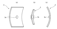
- 1 is a first embodiment of the present invention, showing a balance weight of one-point fastening type, in which (a) is a plate having a relatively large weight, (b) is a rod having a relatively small weight, (c ) Is a longitudinal sectional view of the same figure (a) (b).
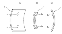
- FIG. 1 shows a first embodiment of the present invention, which shows a balance weight of a two-point fastening type, wherein (a) is a plate having a relatively large weight, (b) is a rod having a relatively small weight, (c ) Is a longitudinal sectional view of the same figure (a) (b).
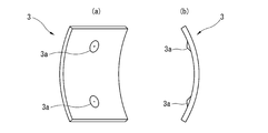
- piece fastening type shown in FIG. 3 is shown, (a) is a perspective view, (b) is a side view.
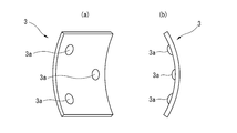
- the balance weight of 3 point fastening type is shown, (a) is a perspective view, (b) is a side view.
- the balance weight of a spot welding type is shown, (a) is a perspective view, (b) is a side view. It is the schematic of the spot welding apparatus of balance weight.
- the balance weight of a riveting type is shown, (a) is a perspective view, (b) is a side view. The procedure of attaching the balance weight shown in FIG. 13 is shown, where (a) is a step of welding a rivet, (b) is a step of inserting the weight main body into the rivet, and (c) is a step of propeller shaft It is a cross-sectional view. It is a cross-sectional view of the propeller shaft which shows 3rd Embodiment of this invention.
- FIG. 1 shows a semi-longitudinal cross-sectional view of a propeller shaft 1 showing the entire form of a propeller shaft 1. Further, in the description of this figure, for convenience, the left side in the figure is described as “front” and the right side is “rear”, and the direction along the rotation axis Z of the propeller shaft 1 is “axial direction”, around the rotation axis Z The direction is described as “circumferential direction”.
- the propeller shaft 1 has a shaft member 2 that transmits the driving force of a driving source (not shown). Joints J1 and J2 are provided at front and rear end portions of the shaft member 2.
- the propeller shaft 1 has the front end side linked to the transmission not shown and the rear end linked to the differential not shown so that the power input from the transmission not shown is not shown. Transmit to the differential side.
- a balance weight 3 which is a weight made of a plate material of iron-based metal and correcting a rotational unbalance of the propeller shaft 1 is attached.
- the balance weight 3 is provided with a weight sufficient to cancel the rotational unbalance on the opposite side of the rotational axis Z of the portion where the rotational unbalance of the shaft member 2 occurs. Thereby, the said rotation unbalance is canceled and the vibration and resonance of the propeller shaft 1 by the said rotation unbalance are suppressed.
- FIGS. 2 to 10 show a first embodiment of a power transmission shaft and a method of manufacturing the same according to the present invention.
- the balance weight 3 is attached to the shaft member 2 by projection welding.
- FIG. 2 shows a single-point welding type in which one point is welded, where (a) is a relatively heavy plate-like one, (b) is a relatively small rod-like one, and (c) is the same a)
- the longitudinal cross-sectional view of (b) is shown.
- Fig. 3 shows a two-point fastening type in which two points are welded, where (a) is a relatively heavy plate-like one, (b) is a relatively small rod-like one, and (c) is the same a)
- the longitudinal cross-sectional view of (b) is shown.
- FIG. 4 shows a modified example of the two-point fastening type shown in FIG. 3, in which (a) is a perspective view and (b) is a side view.
- FIG. 5 shows a three-point fastening type in which three points are welded, where (a) is a perspective view and (b) is a side view.
- the balance weight 3 has a substantially uniform thickness (plate thickness) and the shaft member 2
- the plate member is a substantially rectangular plate that is rectangular in plan view and is long in the circumferential direction, and is curved in the circumferential direction with a curvature corresponding to the curvature of the outer peripheral surface of the shaft member 2.
- the shaft member 2 has a substantially uniform thickness and It may be formed in the shape of an elongated rod curved and extended along the circumferential direction of
- projections 3a as welding projections which project inward from the outside according to the number of welding.
- the projection 3a is integrally formed with the plate by pushing a part of the plate from the outside to the inside. Then, the balance weight 3 is projection-welded to the shaft member 2 through the projection 3 a.
- the projection 3a in addition to a substantially spherical shape having a substantially arc-shaped cross section, as shown in FIG. 4 (a) It may be formed in such a pointed shape, that is, a substantially conical shape having a substantially triangular cross section.
- a sacrificial metal coating 4 in particular, is easily peeled off at the time of welding (during pressure). There is an advantage that strong bonding based on good current can be achieved.
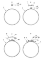
- FIG. 6 shows a variation of the formation mode of the sacrificial metal film 4 formed on the balance weight 3 shown in FIG. 3, in which (a) is formed on the outer surface, (b) is formed on the inner surface, c) shows those formed on the outer side and the inner side, and (d) shows those formed on the outer side and the inner side and the outer peripheral side.
- the balance weight 3 is a sacrificial metal material containing a metal having a larger ionization tendency than the metal (in the present embodiment, “iron-based metal”) constituting the shaft member 2. It is covered by a metal coating 4.
- the sacrificial metal material for example, zinc, magnesium, aluminum or an alloy containing these metals corresponds, and in the present embodiment, “zinc” is adopted.
- the sacrificial metal coating 4 is a part of the balance weight 3, for example, only the outer side 3b as shown in FIG. 6 (a), only the inner side 3c as shown in FIG. 6 (b). It can be formed only on both sides of the outer side 3b and the inner side 3c.
- the sacrificial metal film 4 may be formed on the entire balance weight 3 as shown in FIG. 6D, that is, on all the surfaces of the outer surface 3b and the inner surface 3c and the outer surface 3d.
- the sacrificial metal film 4 can be formed on part of the balance weight 3 by electroplating, spray or the like, for example, before or after the welding of the balance weight 3.
- the sacrificial metal film 4 may be formed on the balance weight 3 by molding the balance weight 3 from a steel plate to which the sacrificial metal film 4 has been applied in advance, such as press forming a plated steel plate as described later.
- the balance weight 3 press-molds a plated steel plate as described later, and then adds the sacrificial metal coating 4 to the outer peripheral surface (cutting surface), and the entire balance weight 3 is the sacrificial It is desirable to be covered by the metal coating 4.
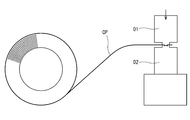
- FIG. 7 shows a schematic view of a forming apparatus of the balance weight 3
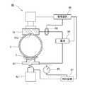
- FIG. 8 shows a schematic view of a projection welding apparatus of the balance weight 3.
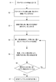
- FIG. 9 shows a flow chart showing the mounting procedure of the balance weight 3.
- a plurality of coated balance weights 3 of different weights are prepared.
- a known plated steel plate CP which is a strip-shaped material wound in a coil shape, is formed by pressing the sacrificial metal coating 4 in advance on both the outer surface 3b and the inner surface 3c.
- the balance weight 3 on which the sacrificial metal film 4 is formed is manufactured. Specifically, the tip of the plated steel plate CP wound in a coil shape is drawn in, sandwiched between the upper die D1 and the lower die D2, and punched out by a punch (not shown) provided on the upper die D1. Thus, the balance weight 3 is molded.
- the protrusions 3a shown in FIGS. 2 to 5 are also formed at the time of molding. The above corresponds to the "step of preparing balance weight" according to the present invention.
- the balance weight 3 is attached to the propeller shaft 1 according to the flowchart shown in FIG. That is, after the propeller shaft 1 is assembled (step S1), the propeller shaft 1 is mounted on a balance correction machine (not shown) and rotated to measure the rotational balance of the propeller shaft 1 (step S2). ). Then, the amount of rotational unbalance of the propeller shaft 1 and the phase of the unbalance are calculated and output by the balance correction machine (not shown) (step S3).
- the above corresponds to the “step of specifying the attachment position and weight of the balance weight” according to the present invention.
- the balance weight 3 is attached to the shaft member 2 of the propeller shaft 1 based on the measurement result by the balance correction machine (step S4).
- the upper electrode whose shaft member 2 is a fixed electrode so that the mounting position of the balance weight 3 faces the lower electrode 62 based on the measurement result. It is supported by the lower recess 61 a.
- the balance weight 3 of the weight selected based on the measurement result is placed on the lower electrode 62 which is a movable electrode. Thereafter, the lower electrode 62 ascends, and electricity is supplied in a state where the inner peripheral side (protrusion 3a) of the balance weight 3 is pressed against the outer peripheral surface of the shaft member 2, thereby melting the projection 3a.
- the balance weight 3 is welded to the outer peripheral surface of the shaft member 2. The above corresponds to the “step of welding the balance weight to the cylinder” according to the present invention.
- reference numeral 63 denotes a cylinder for raising and lowering the lower electrode 62
- reference numeral 64 denotes a detection coil for detecting a current applied to the upper electrode 61
- reference numeral 65 denotes a displacement amount of the lower electrode 62.
- the displacement sensor to measure is shown.
- reference numeral 66 indicates a management device that manages the power supply 68 based on the detection result of the detection coil 64
- reference numeral 67 indicates a determination device that determines the quality of welding based on the determination result of the displacement sensor 65.
- step S5 the rotational balance of the propeller shaft 1 is measured again by the balance correction machine (not shown) (step S5). Then, it is determined whether or not the measured rotational balance is corrected to a predetermined imbalance value or less (step S6).
- step S7 when it is judged Yes, while correction of rotation unbalance is completed (step S7), when it is judged No, it returns to step S4, and balance weight for the part where rotation balance is insufficient.
- the surface of the shaft member 2 to which the balance weight 3 is welded, including the balance weight 3, is painted using, for example, a spray gun or the like (not shown), whereby the propeller shaft 1 is completed.
- a spray gun or the like not shown
- FIG. 19 shows an image showing the mechanism of the progress of corrosion in the conventional propeller shaft
- FIG. 20 shows an enlarged view of a part A in FIG.
- a coating film C is formed by coating on the outer peripheral surface of the steel pipe 10 in the peripheral region of the balance weight 30, but the coating film C permeates water (H 2 O) not a little.
- the interface B between the coating film C and the steel pipe 10 has a lower oxygen concentration than the gap S between the inner surface of the balance weight 30 and the outer peripheral surface of the steel pipe 10. For this reason, water (H 2 O) transmitted through the coating C is accumulated at the interface B between the coating C and the steel pipe 10, whereby the interface B side becomes an anode and the gap S side becomes a cathode between the interface B and the gap S.
- a so-called "concentration cell (air flow difference cell)" is formed.
- iron ions Fe 2+
- H 2 O water
- Fe ⁇ Fe 2+ + 2e ⁇ iron ions
- O 2 oxygen
- this eluted iron ion (Fe 2+ ) is oxidized by oxygen (O 2 ) in water (H 2 O) to produce iron hydroxide (Fe (OH) 2 ) (2Fe + O 2) + 2H 2 O ⁇ 2Fe (OH) 2 ).
- iron oxyhydroxide (FeOOH) is produced on the interface B side (2Fe (OH) 2 + O 2 ⁇ 2FeOOH). Then, the iron oxyhydroxide (FeOOH) is dehydrated to precipitate red rust (Fe 2 O 3 ), which is an iron oxide (2FeOOH ⁇ Fe 2 O 3 + 2H 2 O).
- the iron oxyhydroxide (FeOOH) generated on the interface B side flows into the gap S side, and the electrons released by the elution of the iron ion (Fe 2+ ) It combines with (e ⁇ ) to form a cathode and black rust (Fe 3 O 4 ) is formed (FeOOH + 2e ⁇ ⁇ 2Fe 3 O 4 + 2H 2 O + OH ⁇ ).
- the pH is increased by black rust (Fe 3 O 4 ), and the anticorrosion effect is exhibited.
- FIG. 10 is an image view showing the mechanism of the progress of corrosion in the propeller shaft 1 according to the present embodiment.
- the entire surface of the balance weight 3 is a sacrificial metal material containing a metal having a larger ionization tendency than the metal (iron-based metal) constituting the shaft member 2 It is covered by a sacrificial metal coating 4 made of ("zinc" in this embodiment).
- the water (H 2 O) passing through the coating film C is adsorbed to the surface of the balance weight 3 by the water (H 2 O), the iron-based metal prior to the iron-based metal constituting the shaft member 2 While zinc ions (Zn 2+ ) constituting the sacrificial metal film 4 having a larger ionization tendency are eluted, electrons (e ⁇ ) are released (Zn ⁇ Zn 2+ + 2e ⁇ ). Then, electrons (e ⁇ ) emitted from zinc flow from the balance weight 3 side to the shaft member 2 side. As a result, the balance weight 3 side becomes an anode and the shaft member 2 side becomes a cathode.
- the eluted zinc ion (Zn 2+ ) is oxidized by oxygen (O 2 ) in water (H 2 O), so that the sacrificial metal film 4 made of the zinc is white.
- rust (ZnO + Zn (OH) 2 ) is generated (2Zn + O 2 + 2H 2 O ⁇ ZnO + Zn (OH) 2).
- the white rust (ZnO + Zn (OH) 2 ) becomes a protective film because of a dense thin film, and the progress of the corrosion of the sacrificial metal film 4 on the balance weight 3 side is suppressed.
- zinc (Zn) constituting the sacrificial metal film 4 is eluted earlier than iron-based metal (Fe) constituting the shaft member 2 as described above, and balance is achieved.
- the sacrificial anticorrosive effect is exhibited based on the generation of the current from the weight 3 side to the shaft member 2 side.
- the unique effects based on the following configuration can be achieved to solve the problems of the conventional propeller shaft.
- the propeller shaft 1 is a power transmission shaft having a shaft member 2 which is a cylindrical body made of iron-based metal, and a balance weight 3 made of iron-based metal welded to the outer peripheral surface of the shaft member 2. At least a part of the weight 3 is covered with a sacrificial metal coating 4 made of a sacrificial anticorrosive material (in the present embodiment, “zinc”) containing a metal having a higher ionization tendency than the metal constituting the shaft member 2.
- a sacrificial metal coating 4 made of a sacrificial anticorrosive material (in the present embodiment, “zinc”) containing a metal having a higher ionization tendency than the metal constituting the shaft member 2.
- the sacrificial metal coating 4 made of a sacrificial anticorrosive material containing a metal having a larger ionization tendency than the iron-based metal constituting the shaft member 2 It is done. For this reason, the sacrificial metal film 4 of the balance weight 3 corrodes earlier than the shaft member 2, and the shaft member 2 side in the peripheral region of the balance weight 3 becomes cathodically. Thereby, local corrosion of the shaft member 2 in the circumferential area of the balance weight 3 can be suppressed.
- the balance weight 3 is formed of a plate material, and the sacrificial anticorrosive material (the sacrificial metal film 4) covers the surface of the balance weight 3.
- the sacrificial anticorrosive material covers at least the side surface of the balance weight 3 on the side of the shaft member 2 which is a cylindrical body or the side surface on the opposite side to the shaft member 2 ing.
- the sacrificial anticorrosive effect can be sustained longer, and the durability of the propeller shaft 1 is improved in the long run. It can be done.
- the sacrificial anticorrosive material is preferably made of zinc, magnesium, aluminum, or an alloy containing these metals, and the sacrificial anticorrosive material according to the present embodiment is made of "zinc".
- the sacrificial anticorrosive material As described above, by forming the sacrificial anticorrosive material with zinc, magnesium, aluminum, or an alloy containing any of metals having a relatively larger ionization tendency than iron, it is possible to obtain the relatively large sacrificial anticorrosive effect. Can. These metals also have the advantage of being easy to handle.
- a manufacturing method of a power transmission shaft having the shaft member 2 which is a cylinder made of iron-based metal, and the balance weight 3 which is made of iron-based metal and attached to the outer peripheral surface of the shaft member 2.
- a sacrificial anticorrosive material a sacrificial metal coating 4
- a metal having a higher ionization tendency than the metal constituting the shaft member 2
- the sacrificial metal coating 4 made of a sacrificial anticorrosive material containing a metal having a larger ionization tendency than the iron-based metal constituting the shaft member 2 It is done. For this reason, the sacrificial metal film 4 of the balance weight 3 corrodes earlier than the shaft member 2, and the shaft member 2 side in the peripheral region of the balance weight 3 becomes cathodically. Thereby, local corrosion of the shaft member 2 in the circumferential area of the balance weight 3 can be suppressed.
- the balance weight 3 is formed of a plate material, and the sacrificial anticorrosive material covers the welding surface of the balance weight 3 with the shaft member 2.
- the sacrificial anticorrosive material is easily eluted by the water accumulated in the gap S, and the higher sacrificial corrosion effect can be obtained. You can get it.
- the balance weight 3 is formed to be curved with a curvature corresponding to the curvature of the outer peripheral surface of the shaft member 2, and a projection 3a that is a projection for welding is formed on the contact surface with the shaft member 2. ing.
- the balance weight 3 can be attached easily and firmly. Moreover, when the welding surface is covered with a sacrificial anticorrosive material, by providing the projection 3a on the welding surface, the projection 3a serving as the welding point and the shaft member 2 are in point contact, and welding (during energization) Can reduce the influence of the sacrificial anticorrosive material.
- the balance weight 3 is formed by punching out a strip-shaped member plated with the sacrificial anticorrosive material (the sacrificial metal film 4) with a press.
- productivity is improved and the manufacturing cost of the propeller shaft 1 can be reduced by punching out and molding the so-called plated steel plate on which the sacrificial metal coating 4 is formed in advance by using the balance weight 3 in a press manner.
- a method of press-molding the above-described plated steel sheet is described as an embodiment in which the balance weight 3 is coated with the sacrificial anticorrosive material. It is not limited.
- the sacrificial weight on the balance weight 3 it is also possible to press-mold a steel plate which is a strip-shaped material wound in a coil shape, for example, and then coat the sacrificial corrosion resistant material.
- the balance weight 3 may be coated with a sacrificial anticorrosive material after punching a strip-shaped member by a press.
- the entire balance weight 3 is coated with a sacrificial anticorrosive material (a sacrificial metal film 4).
- the entire balance weight 3 is covered with the sacrificial metal film 4 to obtain the higher sacrificial protection effect, and the sacrificial protection effect can be maintained for a longer time.
- 11 and 12 show a modification of the first embodiment of the present invention.
- the said modification is what attached the balance weight 31 to the shaft member 2 by spot welding, Comprising: About another structure, it is the same as that of the said 1st Embodiment. Therefore, about the same composition as a 1st embodiment of the above, concrete explanation is omitted by attaching the same numerals as a 1st embodiment.
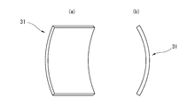
- FIG. 11 is a view showing the form of the balance weight 31 to be spot-welded, where (a) is a perspective view and (b) is a side view.
- the balance weight 31 is a substantially rectangular plate having a substantially uniform thickness (plate thickness) and having a rectangular shape in plan view that is long in the circumferential direction of the shaft member 2. Furthermore, the balance weight 31 is curved in the circumferential direction and formed with a curvature corresponding to the curvature of the outer peripheral surface of the shaft member 2. In other words, the balance weight 31 according to the present modification is the balance weight 3 according to the first embodiment from which the protrusion 3 a is removed.
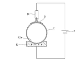
- FIG. 12 shows a schematic view of a spot welding apparatus for welding the balance weight 31.
- the balance weight 31 is attached to the outer peripheral surface of the shaft member 2 along the flowchart shown in FIG. 9 as in the first embodiment.
- the shaft is mounted such that the mounting position of the balance weight 31 faces the upper electrode E1 based on the measurement result of step S3 of FIG.
- the member 2 is placed in the upper recess E2a of the lower electrode E2 which is a fixed electrode.
- the balance weight 31 is placed on the upper part of the shaft member 2 supported by the lower electrode E2 and at a predetermined attachment position based on the measurement result.
- the upper electrode E1 is lowered, and the balance weight 31 is a shaft member by the current applied from the power source P being conducted in a state where the inner side surface 31c of the balance weight 31 is pressed against the outer peripheral surface of the shaft member 2 Welded to the outer peripheral surface of 2.
- Second Embodiment 13 and 14 show a second embodiment of a power transmission shaft and a method of manufacturing the same according to the present invention.
- the balance weight 32 is riveted to the shaft member 2, and the other configuration is the same as that of the first embodiment. Therefore, about the same composition as a 1st embodiment of the above, the explanation is omitted by attaching the same numerals.
- FIG. 13 is a view showing the form of the balance weight 32, where (a) is a perspective view and (b) is a side view.
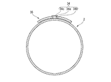
- the balance weight 32 has a weight main body 33 as a weight made of an iron-based material, and a rivet 34 as an attachment member for attaching the weight main body 33 to the shaft member 2.
- the weight main body 33 is a substantially rectangular plate material having a substantially uniform thickness (plate thickness) and having a rectangular shape in a plan view elongated in the circumferential direction of the shaft member 2 and corresponds to the curvature of the outer peripheral surface of the shaft member 2 It is curved and formed in the circumferential direction with the curvature which has. Further, a through hole 33a through which a rivet 34 (a rivet main body 34a described later) penetrates is formed at a substantially central position in a plan view of the weight main body 33.
- the rivet 34 has a substantially cylindrical shape, and is formed in an enlarged diameter shape at one end portion of the rivet main body 34 a penetrating the through hole 33 a of the weight main body 33 and the rivet main body 34 a and is welded to the outer peripheral surface of the shaft member 2 And a flange portion 34b. That is, the rivet 34 is welded to the outer peripheral surface of the shaft member 2 via the flange portion 34 b, and the balance weight 32 is fixed to the shaft member 2 by caulking the rivet body 34 a.
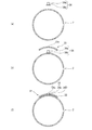
- FIG. 14 shows a cross-sectional view of the propeller shaft 1 (shaft member 2), which shows, among other things, a method of attaching the balance weight 32 in the method of manufacturing the propeller shaft 1.
- 14A shows a process of welding the rivet 34
- FIG. 14B shows a process of inserting the weight main body 33 into the rivet 34
- FIG. 14C shows a process of caulking the rivet 34. There is.
- the balance weight 32 is attached to the outer peripheral surface of the shaft member 2 in accordance with the flowchart shown in FIG.
- the rivet 34 is welded through the flange portion 34b.
- the rivet main body 34a of the rivet 34 welded to the outer periphery of the shaft member 2 is specified based on the measurement result from the other end side of the rivet main body 34a.
- the weight body 33 of the specified weight is inserted.
- the other end of the rivet main body 34a penetrating the through hole 33a of the weight main body 33 is crushed (crimped) to form a crimped portion 34c.
- the weight main body 33 is sandwiched between the caulking portion 34c and the flange portion 34b, and is fixed to the shaft member 2 through the rivet 34.
- the balance weight 32 is a weight having the rivet 34 made of iron-based metal and the through hole 33 a made of iron-based metal and into which the rivet 34 is inserted.
- a weight body 33 is provided, and at least one of the rivet 34 and the weight body 33 is coated with a sacrificial anticorrosive material.
- the balance weight 32 has a rivet 34 made of iron-based metal, and a weight main body 33 made of iron-based metal and formed with a through hole into which the rivet 34 is inserted. At least one of 34 and the weight main body 33 is covered with a sacrificial anticorrosive material, and the rivet 34 is welded to fix the weight main body 33 to the shaft member 2 which is a cylindrical body.
- the balance weight 32 is not directly welded to the shaft member 2 but is welded via the rivet 34, thermal effects such as thermal strain on the balance weight 32 can be suppressed.
- the rivet 34 is welded to the shaft member 2 via the flange portion 34 b relatively thinner than the balance weight 32, the rivet 34 can be easily fixed to the shaft member 2.
- the balance weight 32 is fixed by caulking the rivet 34, the balance weight 32 can be fixed more easily and firmly than when the balance weight 32 is directly welded to the shaft member 2 it can.
- At least one of the weight main body 33 and the rivet 34 may be covered with a sacrificial anticorrosive material.
- a sacrificial anticorrosive material it is possible to suppress the progress of the local corrosion of the shaft member 2 in the circumferential area of the balance weight 32 by the sacrificial anticorrosive effect.
- FIG. 15 shows a third embodiment of a power transmission shaft and a method of manufacturing the same according to the present invention.
- a sacrificial metal 5 described later is directly provided to a part of the balance weight 3, and the other configuration is the same as that of the first embodiment. Therefore, about the same composition as a 1st embodiment of the above, the explanation is omitted by attaching the same numerals.
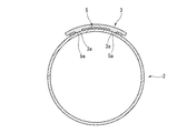
- FIG. 15 shows a cross-sectional view of the propeller shaft 1 showing an attachment aspect of the balance weight 3 and the sacrificial metal 5.
- the sacrificial metal 5 having a larger ionization tendency than the metal (iron-based metal) constituting the shaft member 2 contacts a part of the inner side surface 3 c which is the surface of the balance weight 3 It is provided to let
- the balance weight 3 is projection-welded to the shaft member 2 via two projecting portions 3a separated in the longitudinal direction (the circumferential direction of the shaft member 2).
- the sacrificial metal 5 is a plate made of a metal having a higher ionization tendency than the metal (iron-based metal) constituting the shaft member 2, for example, “zinc”. That is, the sacrificial metal 5 has a substantially rectangular plate shape having a substantially uniform thickness (plate thickness) and having a rectangular shape in a plan view elongated in the circumferential direction of the shaft member 2, and the curvature of the outer peripheral surface of the shaft member 2 It is curved in the circumferential direction and formed with a corresponding curvature.
- the sacrificial metal 5 has two engagement holes 5 a at positions corresponding to the protrusions 3 a of the balance weight 3, in which the protrusions 3 a are engaged. That is, the sacrificial metal 5 is positioned by engaging the projections 3 a of the balance weight 3 with the engagement holes 5 a. The sacrificial metal 5 is fixed by being sandwiched between the balance weight 3 and the shaft member 2 by welding the balance weight 3 to the shaft member 2.
- the projections 3 a are engaged with the engagement holes 5 a of the sacrificial metal 5 so that the sacrificial metal 5 is positioned inside the balance weight 3. Then, in the state of being positioned, the integrated balance weight 3 and the sacrificial metal 5 are projection-welded to the shaft member 2 through the respective projections 3a. As a result, the sacrificial metal 5 and the weight main body 33 are sandwiched by the flange portion 34 b and the caulking portion 34 c, and are fixed together to the shaft member 2 via the rivet 34.
- the propeller shaft 1 includes the shaft member 2 which is a cylindrical body made of iron-based metal, and the balance weight 3 made of iron-based metal welded to the outer peripheral surface of the shaft member 2.
- a sacrificial metal (“zinc" in the present embodiment) having a larger ionization tendency than that of the metal constituting the shaft member 2 is provided in at least a part of the balance weight 3 as a power transmission shaft.
- the sacrificial metal 5 containing a metal having a larger ionization tendency than the iron-based metal constituting the shaft member 2. For this reason, the sacrificial metal 5 is corroded earlier than the shaft member 2, and the shaft member 2 side in the peripheral region of the balance weight 3 is cathodized as in the first embodiment. Thereby, local corrosion of the shaft member 2 in the circumferential area of the balance weight 3 can be suppressed.
- the balance weight 3 is formed of a plate material, and the sacrificial metal 5 is provided in contact with the surface of the balance weight 3.
- the sacrificial metal 5 in contact with the surface of the balance weight 3, the sacrificial metal 5 (zinc) is easily eluted earlier than the iron-based metal, and the propeller shaft 1 is produced by the sacrificial corrosion effect. Durability can be effectively improved.
- the balance weight 3 which is a plate material has the protrusion 3 a, and the sacrificial metal 5 is positioned by the protrusion 3 a.
- the sacrificial metal 5 is positioned by the projection 3 a of the balance weight 3, the mounting workability of the sacrificial metal 5 is improved, and the manufacturing cost of the propeller shaft 1 can be reduced.
- the sacrificial metal 5 is provided between the shaft member 2 and the balance weight 3.
- the sacrificial metal 5 between the shaft member 2 and the balance weight 3, the relatively large surface area of the balance weight 3 is covered with the sacrificial metal 5. Therefore, the sacrificial corrosion effect can be sustained longer, and the durability of the propeller shaft 1 can be improved in the long run.
- the sacrificial metal 5 is provided between the shaft member 2 and the balance weight 3 closer to the shaft member 2, so that electrons emitted by the elution of the sacrificial metal 5 easily move to the shaft member 2 side, The sacrificial anticorrosive effect can be exhibited more effectively.
- the sacrificial anticorrosive material is preferably made of zinc, magnesium, aluminum, or an alloy containing these metals, and the sacrificial anticorrosive material according to the present embodiment is made of "zinc".
- the sacrificial anticorrosive material is composed of zinc, magnesium, aluminum, or an alloy containing these, which is a metal having a relatively larger ionization tendency than iron, whereby the relatively high sacrificial anticorrosive effect can be obtained. You can get it.
- These metals also have the advantage of being easy to handle.
- Modification 16 and 17 show a modification of the third embodiment of the present invention.
- the said modification is what balance weight 3 and the sacrificial metal 5 were attached to the shaft member 2 by the rivet 34, and the other structure is the same as that of the said 1st Embodiment. Therefore, about the same composition as a 1st embodiment of the above, concrete explanation is omitted by attaching the same numerals as a 1st embodiment.
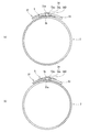
- FIG. 16 (a) is a cross-sectional view of the propeller shaft 1 provided with the sacrificial metal 5 in contact with the inner surface 3c of the balance weight 3.
- FIG. 16 (b) shows a cross-sectional view of the propeller shaft 1 in which the sacrificial metal 5 is provided in contact with the outer surface 3 b of the balance weight 3.
- the two projections 3a according to the third embodiment are eliminated, and the weight main body 33 having the through hole 33a at a substantially central position in plan view is the second one. As in the embodiment, it is fixed to the shaft member 2 through the rivets 34.
- the rivet 34 is welded to the shaft member 2 via the flange portion 34b, as in the second embodiment.
- the two engagement holes 5a according to the third embodiment are eliminated, and instead, a through hole through which the rivet 34 (the rivet main body 34a) penetrates at substantially the center position of the sacrificial metal 5 in plan view. 5b is formed. That is, the sacrificial metal 5 according to the present modification is disposed inside the weight main body 33 of the balance weight 32, and is fixed together with the weight main body 33 by the rivet 34 penetrating the through hole 5b.
- the sacrificial metal 5 may be disposed outside the weight body 33 of the balance weight 32 and may be crimped and fixed by the rivet 34.
- FIG. 17 shows a cross-sectional view of the propeller shaft 1 (shaft member 2) showing, among the methods of manufacturing the propeller shaft 1, among other things, the method of attaching the balance weight 32 and the sacrificial metal 5.
- 17 (a) is a step of welding the rivet 34
- FIG. 17 (b) is a step of inserting the sacrificial metal 5 into the rivet 34
- FIG. 17 (c) is a step of inserting the weight main body 33 into the rivet 34.
- a process, FIG. 17 (d) shows a process of caulking the rivet 34. As shown in FIG.
- the balance weight 32 is attached to the outer peripheral surface of the shaft member 2 along the flowchart shown in FIG. 9 as in the first embodiment.
- the rivets 34 are provided on the outer peripheral surface of the shaft member 2 at the mounting position specified based on the measurement result in step S3 of FIG. , Welded through the flange portion 34b.
- the sacrificial metal 5 is inserted into the rivet body 34a of the rivet 34 welded to the outer periphery of the shaft member 2 from the other end side of the rivet body 34a.
- the weight main body 33 of the weight specified based on the measurement result is inserted in a superimposed manner on the sacrificial metal 5 from the other end side of the rivet main body 34a.
- the balance weight 32 is a weight having the rivet 34 made of iron-based metal and the through hole 33 a made of iron-based metal and into which the rivet 34 is inserted.
- a shaft member 2 having a weight main body 33, a through hole 5b into which a rivet 34 is inserted is formed in the sacrificial metal 5, and the balance weight main body 33 and the sacrificial metal 5 are cylindrical via the rivet 34. It is fixed to
- the sacrificial metal 5 is fixed together with the weight body 33 of the balance weight 32 via the rivets 34. For this reason, the sacrificial metal 5 and the weight main body 33 can be fixed easily and firmly while suppressing the thermal influence of welding on the sacrificial metal 5 and the weight main body 33.
- the sacrificial metal 5 is provided between the weight main body 33 of the balance weight 32 and the rivet 34.
- the sacrificial metal 5 is provided between the weight body 33 and the rivet 34 that make up the balance weight 32, so that the sacrificial metal 5 can be fastened together by the rivet 34. Thereby, the sacrificial metal 5 can be easily attached, and the manufacturing cost of the propeller shaft 1 can be reduced.
- FIG. 18 shows a reference example of a power transmission shaft according to the present invention.
- the balance weight 35 itself is formed of the sacrificial metal 5, and the other configuration is the same as that of the second embodiment. Therefore, about the same composition as a 1st embodiment of the above, the explanation is omitted by attaching the same numerals.
- FIG. 18 shows a cross-sectional view of the propeller shaft 1 showing an attachment aspect of the balance weight 35. As shown in FIG.
- the balance weight 35 is formed of a sacrificial metal material containing a metal having a larger ionization tendency than the metal (in the embodiment, “iron-based metal”) constituting the shaft member 2. It is done.
- the sacrificial metal material for example, zinc, magnesium, aluminum or an alloy containing these metals corresponds, and in the present embodiment, “zinc” is adopted.
- the present invention is not limited to the configurations and aspects exemplified in the above embodiments and the like.
- the shapes of the balance weight 3 and the like, and the shapes and arrangement (range) of the sacrificial metal coating 4 and the sacrificial metal 5 If it is a form which can produce the effect of the said this invention, according to the specification, cost, etc. of application object, it can freely change.
- the power transmission shaft is a power transmission shaft including a cylinder made of iron-based metal and a balance weight made of iron-based metal welded to the outer peripheral surface of the cylinder. At least a part of the balance weight is coated with a sacrificial anticorrosive material containing a metal having a higher ionization tendency than the metal constituting the cylinder.
- the balance weight is formed of a plate material, and the sacrificial anticorrosive material covers the surface of the balance weight.
- the sacrificial anticorrosive material covers at least the side surface of the balance weight on the cylinder side or the side opposite to the cylinder. ing.
- the sacrificial anticorrosive material is made of zinc, magnesium, aluminum, or an alloy containing any of these metals.
- the balance weight is a rivet made of an iron-based metal, and a weight made of an iron-based metal and having a through hole into which the rivet is inserted. And at least one of the rivet and the weight is coated with the sacrificial anticorrosive material.
- the power transmission shaft based on the above-described embodiment includes, as one aspect thereof, a cylinder made of iron-based metal, and a balance weight made of iron-based metal welded to the outer peripheral surface of the cylinder.
- the sacrificial metal having a higher ionization tendency than the metal constituting the cylinder is provided on at least a part of the balance weight.
- the balance weight is formed of a plate, and the sacrificial metal is provided in contact with the surface of the balance weight.
- the plate has a protrusion, and the sacrificial metal is positioned by the protrusion.
- the sacrificial metal is provided between the cylinder and the balance weight.
- the sacrificial metal is made of zinc, magnesium, aluminum, or an alloy containing these metals.
- the balance weight is a rivet made of an iron-based metal, and a weight made of an iron-based metal and having a through hole into which the rivet is inserted.
- the sacrificial metal is formed with a through hole into which the rivet is inserted, and the balance weight and the sacrificial metal are fixed to the cylinder through the rivet.
- the sacrificial metal is provided between the balance weight and the rivet.
- a power transmission shaft having a cylinder made of iron-based metal and a balance weight made of iron-based metal and attached to the outer peripheral surface of the cylinder.
- the balance weight is formed of a plate material, and the sacrificial anticorrosive material covers a welding surface of the balance weight with the cylinder.
- the balance weight is curved and formed with a curvature corresponding to the curvature of the outer peripheral surface of the cylinder, A welding projection is formed on the contact surface.
- the balance weight is formed by punching out a strip member plated with the sacrificial anticorrosive material with a press.
- the balance weight is coated with the sacrificial anticorrosive material after punching a strip member by a press.
- the entire balance weight is coated with the sacrificial anticorrosive material.
- the balance weight is formed of a rivet made of iron-based metal, and a through hole into which the rivet is inserted. And at least one of the rivet and the weight is covered with the sacrificial anticorrosive material, and the weight is fixed to the cylindrical body by welding the rivet.
Landscapes
- Engineering & Computer Science (AREA)
- General Engineering & Computer Science (AREA)
- Mechanical Engineering (AREA)
- Chemical & Material Sciences (AREA)
- Physics & Mathematics (AREA)
- Acoustics & Sound (AREA)
- Aviation & Aerospace Engineering (AREA)
- Ocean & Marine Engineering (AREA)
- Wood Science & Technology (AREA)
- Life Sciences & Earth Sciences (AREA)
- Materials Engineering (AREA)
- Organic Chemistry (AREA)
- Transportation (AREA)
- Combustion & Propulsion (AREA)
- Inorganic Chemistry (AREA)
- Shafts, Cranks, Connecting Bars, And Related Bearings (AREA)
- Motor Power Transmission Devices (AREA)
- Connection Of Plates (AREA)
- Standing Axle, Rod, Or Tube Structures Coupled By Welding, Adhesion, Or Deposition (AREA)
Abstract
Description
図1は、プロペラシャフト1の全体の形態を表したプロペラシャフト1の半縦断面図を示している。また、本図の説明では、便宜上、図中の左側を「前」、右側を「後」として説明すると共に、プロペラシャフト1の回転軸線Zに沿う方向を「軸方向」、回転軸線Z周りの方向を「周方向」として説明する。
図2~図10は、本発明に係る動力伝達軸及びその製造方法の第1実施形態を示している。なお、本実施形態は、バランスウエイト3を、軸部材2にプロジェクション溶接によって取り付けたものである。
図2~図5は、プロジェクション溶接するバランスウエイト3の形態のバリエーションを示している。図2は、1点を溶接する1点留めタイプを示し、(a)は比較的重量の大きい板状のもの、(b)は比較的重量の小さい棒状のもの、(c)は同図(a)(b)の縦断面図を示している。図3は、2点を溶接する2点留めタイプを示し、(a)は比較的重量の大きい板状のもの、(b)は比較的重量の小さい棒状のもの、(c)は同図(a)(b)の縦断面図を示している。図4は、図3に示す2点留めタイプの変形例を示し(a)は斜視図、(b)は側面図を示す。図5は、3点を溶接する3点留めタイプを示し、(a)は斜視図、(b)は側面図を示す。
以下、本発明に係る動力伝達軸の製造方法であって、とりわけバランスウエイト3の取付方法について、図7~図9に基づいて説明する。図7はバランスウエイト3の成型装置の概略図を示し、図8はバランスウエイト3のプロジェクション溶接装置の概略図を示している。さらに、図9は、バランスウエイト3の取付手順を表したフローチャートを示している。
図19は、従来のプロペラシャフトにおける腐食進行のメカニズムを表したイメージ図を示し、図20は、図19中のA部の拡大図を示している。
前記第1実施形態では、バランスウエイト3を溶接する具体的な方法として周知のプロジェクション溶接を採用したものを例示して説明したが、当該溶接手段としては、プロジェクション溶接に限定されるものではない。換言すれば、本発明の作用効果を担保し得る、あらゆる溶接手段を採用でき、その他の一例として、以下に、バランスウエイト31を、スポット溶接をもって軸部材2に取り付ける態様を示す。
図11は、スポット溶接するバランスウエイト31の形態を表した図であり、(a)は斜視図、(b)は側面図を示している。
図12は、バランスウエイト31の溶接に供するスポット溶接装置の概略図を示している。
以上のような変形例であっても、前記第1実施形態とほぼ同様の作用効果が奏せられる。また、とりわけ、前記スポット溶接を採択することで、バランスウエイト31をより簡易に取り付けることが可能となって、プロペラシャフト1の製造コストをより低減することができる。
図13、図14は、本発明に係る動力伝達軸及びその製造方法の第2実施形態を示している。なお、本実施形態では、軸部材2に対してバランスウエイト32をリベット留めしたものであり、他の構成については前記第1実施形態と同様である。よって、前記第1実施形態と同じ構成については、同一の符号を付すことで、その説明を省略する。
図13は、バランスウエイト32の形態を表した図であり、(a)は斜視図、(b)は側面図を示している。
図14は、プロペラシャフト1の製造方法のうち、とりわけバランスウエイト32の取付方法を表した、プロペラシャフト1(軸部材2)の横断面図を示している。なお、図14(a)は、リベット34を溶接する工程、図14(b)は、ウエイト本体33をリベット34に挿入する工程、図14(c)は、リベット34をかしめる工程を示している。
以上のように、本実施形態に係るプロペラシャフト1では、バランスウエイト32は、鉄系金属からなるリベット34と、鉄系金属からなりリベット34が挿入される貫通孔33aが形成された錘であるウエイト本体33と、を有し、リベット34とウエイト本体33の少なくともどちらか一方が、犠牲防食材により被覆されている。
図15は、本発明に係る動力伝達軸及びその製造方法の第3実施形態を示している。なお、本実施形態では、バランスウエイト3の一部に対して後述の犠牲金属5が直接設けられたもので、他の構成については前記第1実施形態と同様である。よって、前記第1実施形態と同じ構成については、同一の符号を付すことで、その説明を省略する。
図15は、バランスウエイト3及び犠牲金属5の取付態様を表したプロペラシャフト1の横断面図を示している。
以上のように、本実施形態に係るプロペラシャフト1は、鉄系金属からなる筒体である軸部材2と、軸部材2の外周面に溶接される鉄系金属からなるバランスウエイト3と、を有する動力伝達軸であって、バランスウエイト3の少なくとも一部に、軸部材2を構成する金属よりもイオン化傾向の大きい犠牲金属(本実施形態では「亜鉛」)が設けられている。
図16、図17は、本発明の第3実施形態の変形例を示す。当該変形例は、バランスウエイト3及び犠牲金属5がリベット34によって軸部材2に取り付けられたものであり、他の構成については前記第1実施形態と同様である。よって、前記第1実施形態と同じ構成については、第1実施形態と同一の符号を付すことで、具体的な説明を省略する。
図17は、プロペラシャフト1の製造方法のうち、とりわけバランスウエイト32及び犠牲金属5の取付方法を表した、プロペラシャフト1(軸部材2)の横断面図を示している。なお、図17(a)は、リベット34を溶接する工程、図17(b)は、犠牲金属5をリベット34に挿入する工程、図17(c)は、ウエイト本体33をリベット34に挿入する工程、図17(d)は、リベット34をかしめる工程を示している。
以上のように、本変形例に係るプロペラシャフト1では、バランスウエイト32は、鉄系金属からなるリベット34と、鉄系金属からなりリベット34が挿入される貫通孔33aが形成された錘であるウエイト本体33と、を有し、犠牲金属5には、リベット34が挿入される貫通孔5bが形成され、バランスウエイト本体33及び犠牲金属5が、リベット34を介して筒体である軸部材2に固定されている。
図18は、本発明に係る動力伝達軸の参考例を示している。なお、本参考例では、バランスウエイト35自体が前記犠牲金属5により形成されたもので、他の構成については前記第2実施形態と同様である。よって、前記第1実施形態と同じ構成については、同一の符号を付すことで、その説明を省略する。
図18は、バランスウエイト35の取付態様を表したプロペラシャフト1の横断面図を示している。
以上、本参考例のように、バランスウエイト35自体が前記犠牲防食材で形成されることによっても、前記第2実施形態と同様の犠牲防食効果が得られ、プロペラシャフト1の耐久性を向上させることができる。
Claims (19)
- 鉄系金属からなる筒体と、
前記筒体の外周面に溶接される鉄系金属からなるバランスウエイトと、
を有する動力伝達軸であって、
前記バランスウエイトの少なくとも一部が、前記筒体を構成する金属よりもイオン化傾向の大きい金属を含有する犠牲防食材によって被覆されていることを特徴とする動力伝達軸。 - 前記バランスウエイトは、板材によって形成され、
前記犠牲防食材は、前記バランスウエイトの表面を被覆していることを特徴とする請求項1に記載の動力伝達軸。 - 前記犠牲防食材は、少なくとも前記バランスウエイトのうち、前記筒体側の側面、又は前記筒体とは反対側の側面を被覆していることを特徴とする請求項2に記載の動力伝達軸。
- 前記犠牲防食材は、亜鉛、マグネシウム、アルミニウム、又はこれらの金属を含む合金からなることを特徴とする請求項1に記載の動力伝達軸。
- 前記バランスウエイトは、
鉄系金属からなるリベットと、
鉄系金属からなり前記リベットが挿入される貫通孔が形成された錘と、
を有し、
前記リベットと前記錘の少なくともどちらか一方が、前記犠牲防食材により被覆されていることを特徴とする請求項1に記載の動力伝達軸。 - 鉄系金属からなる筒体と、
前記筒体の外周面に溶接される鉄系金属からなるバランスウエイトと、
を有する動力伝達軸であって、
前記バランスウエイトの少なくとも一部に、前記筒体を構成する金属よりもイオン化傾向の大きい犠牲金属が設けられていることを特徴とする動力伝達軸。 - 前記バランスウエイトは、板材によって形成され、
前記犠牲金属は、前記バランスウエイトの表面に接触させて設けられていることを特徴とする請求項6に記載の動力伝達軸。 - 前記板材は、突起部を有し、
前記犠牲金属は、前記突起部によって位置決めされていることを特徴とする請求項7に記載の動力伝達軸。 - 前記犠牲金属は、前記筒体と前記バランスウエイトとの間に設けられていることを特徴とする請求項7に記載の動力伝達軸。
- 前記犠牲金属は、亜鉛、マグネシウム、アルミニウム、又はこれらの金属を含む合金からなることを特徴とする請求項6に記載の動力伝達軸。
- 前記バランスウエイトは、
鉄系金属からなるリベットと、
鉄系金属からなり前記リベットが挿入される貫通孔が形成された錘と、
を有し、
前記犠牲金属には、前記リベットが挿入される貫通孔が形成され、
前記バランスウエイト及び前記犠牲金属は前記リベットを介して前記筒体に固定されていることを特徴とする請求項6に記載の動力伝達軸。 - 前記犠牲金属は、前記バランスウエイトと前記リベットとの間に設けられていることを特徴とする請求項11に記載の動力伝達軸。
- 鉄系金属からなる筒体と、鉄系金属からなり前記筒体の外周面に取り付けられるバランスウエイトと、を有する動力伝達軸の製造方法であって、
少なくとも一部が前記筒体を構成する金属よりもイオン化傾向の大きい金属を含有する犠牲防食材によって被覆された、重さの異なる複数の前記バランスウエイトを準備する工程と、
前記動力伝達軸の回転アンバランスに応じて前記筒体に取り付ける前記バランスウエイトの取付位置及び重量を特定する工程と、
前記特定されたバランスウエイトを前記筒体に溶接する工程と、
前記バランスウエイトを含め、前記筒体を塗装する工程と、
を備えることを特徴とする動力伝達軸の製造方法。 - 前記バランスウエイトは、板材によって形成され、
前記犠牲防食材は、前記バランスウエイトの前記筒体との溶接面を被覆していることを特徴とする請求項13に記載の動力伝達軸の製造方法。 - 前記バランスウエイトは、前記筒体の外周面の曲率に対応する曲率をもって湾曲形成されると共に、前記筒体との接触面に溶接用突起が形成されていることを特徴とする請求項14に記載の動力伝達軸の製造方法。
- 前記バランスウエイトは、前記犠牲防食材をめっきした帯状部材をプレスで打ち抜くことによって形成されることを特徴とする請求項14に記載の動力伝達軸の製造方法。
- 前記バランスウエイトは、帯状部材をプレスによって打ち抜いた後、前記犠牲防食材が被覆されることを特徴とする請求項14に記載の動力伝達軸の製造方法。
- 前記バランスウエイトの全体に、前記犠牲防食材が被覆されていることを特徴とする請求項17に記載の動力伝達軸の製造方法。
- 前記バランスウエイトは、
鉄系金属からなるリベットと、
鉄系金属からなり前記リベットが挿入される貫通孔が形成された錘と、
を有し、
前記リベットと前記錘の少なくともどちらか一方が、前記犠牲防食材により被覆され、
前記リベットを溶接することにより、前記錘が前記筒体に固定されることを特徴とする請求項13に記載の動力伝達軸の製造方法。
Priority Applications (7)
| Application Number | Priority Date | Filing Date | Title |
|---|---|---|---|
| JP2019526675A JP6860952B2 (ja) | 2017-06-30 | 2018-05-18 | 動力伝達軸及びその製造方法 |
| CN202410227538.XA CN118242358A (zh) | 2017-06-30 | 2018-05-18 | 动力传递轴 |
| CN201880037709.5A CN110709270A (zh) | 2017-06-30 | 2018-05-18 | 动力传递轴及其制造方法 |
| KR1020217012315A KR102366548B1 (ko) | 2017-06-30 | 2018-05-18 | 동력 전달축 및 그 제조 방법 |
| US16/612,496 US11512761B2 (en) | 2017-06-30 | 2018-05-18 | Power transmission shaft and method for manufacturing same |
| KR1020197036073A KR102268505B1 (ko) | 2017-06-30 | 2018-05-18 | 동력 전달축 및 그 제조 방법 |
| US17/977,955 US11976704B2 (en) | 2017-06-30 | 2022-10-31 | Power transmission shaft and method for manufacturing same |
Applications Claiming Priority (2)
| Application Number | Priority Date | Filing Date | Title |
|---|---|---|---|
| JP2017-128537 | 2017-06-30 | ||
| JP2017128537 | 2017-06-30 |
Related Child Applications (2)
| Application Number | Title | Priority Date | Filing Date |
|---|---|---|---|
| US16/612,496 A-371-Of-International US11512761B2 (en) | 2017-06-30 | 2018-05-18 | Power transmission shaft and method for manufacturing same |
| US17/977,955 Continuation US11976704B2 (en) | 2017-06-30 | 2022-10-31 | Power transmission shaft and method for manufacturing same |
Publications (1)
| Publication Number | Publication Date |
|---|---|
| WO2019003702A1 true WO2019003702A1 (ja) | 2019-01-03 |
Family
ID=64741414
Family Applications (1)
| Application Number | Title | Priority Date | Filing Date |
|---|---|---|---|
| PCT/JP2018/019227 Ceased WO2019003702A1 (ja) | 2017-06-30 | 2018-05-18 | 動力伝達軸及びその製造方法 |
Country Status (5)
| Country | Link |
|---|---|
| US (2) | US11512761B2 (ja) |
| JP (2) | JP6860952B2 (ja) |
| KR (2) | KR102366548B1 (ja) |
| CN (2) | CN110709270A (ja) |
| WO (1) | WO2019003702A1 (ja) |
Cited By (1)
| Publication number | Priority date | Publication date | Assignee | Title |
|---|---|---|---|---|
| JP2021151860A (ja) * | 2017-06-30 | 2021-09-30 | 日立Astemo株式会社 | 動力伝達軸 |
Families Citing this family (1)
| Publication number | Priority date | Publication date | Assignee | Title |
|---|---|---|---|---|
| US12313007B2 (en) | 2023-05-26 | 2025-05-27 | Pratt & Whitney Canada Corp. | Aircraft powerplant rotating assembly with sacrificial anode(s) |
Citations (6)
| Publication number | Priority date | Publication date | Assignee | Title |
|---|---|---|---|---|
| JP2001193795A (ja) * | 2000-01-06 | 2001-07-17 | Nippon Stud Welding Kk | バランス鋲付回転駆動軸及びバランス鋲 |
| JP2002088806A (ja) * | 2000-09-14 | 2002-03-27 | Komatsu Ltd | 作業用移動機械 |
| JP2011012775A (ja) * | 2009-07-02 | 2011-01-20 | Toho Kogyo Kk | バランスウエイト |
| JP2015113964A (ja) * | 2013-12-13 | 2015-06-22 | 大豊工業株式会社 | 貼着式ホイールバランスウエイトおよびその製造方法 |
| JP2015135144A (ja) * | 2014-01-17 | 2015-07-27 | 株式会社ショーワ | 動力伝達軸 |
| WO2016154239A1 (en) * | 2015-03-26 | 2016-09-29 | Dana Automotive Systems Group, Llc | Laser welding of balance weights to driveshafts |
Family Cites Families (24)
| Publication number | Priority date | Publication date | Assignee | Title |
|---|---|---|---|---|
| US4998448A (en) * | 1982-04-26 | 1991-03-12 | Dana Corporation | Aluminum driveshaft with balancing composition |
| GB2147388B (en) * | 1983-09-29 | 1986-10-08 | Dana Corp | Balance weights |
| US4887989A (en) * | 1987-12-28 | 1989-12-19 | A. O. Smith Corporation | Dynamically balanced driveshaft and method of producing the same |
| JPH02120129A (ja) | 1988-10-28 | 1990-05-08 | Mazda Motor Corp | 軽合金製プロペラシャフトのバランスウエイト取付構造 |
| GB2272041B (en) | 1992-10-28 | 1995-10-25 | Unidrive Pty Ltd | Propeller shafts |
| JP3530236B2 (ja) * | 1994-10-31 | 2004-05-24 | 自動車部品工業株式会社 | プロペラシャフトのバランスウェイト取付方法 |
| JP3503007B2 (ja) * | 1995-08-08 | 2004-03-02 | 東豊工業株式会社 | ホイールバランスウエイトおよびその製造方法 |
| DE19645387C1 (de) * | 1996-11-04 | 1998-04-09 | Daimler Benz Ag | Schweißverbindung von Wuchtgewichten an dünnwandigen Wellen |
| JPH11125312A (ja) | 1997-10-22 | 1999-05-11 | Matsui Seisakusho:Kk | 駆動軸のバランスウエイト用溶接ピース |
| US6619119B1 (en) * | 1998-12-31 | 2003-09-16 | Torque-Traction Technologies, Inc. | Balance weight for vehicular driveshaft |
| US20040000214A1 (en) * | 2002-06-27 | 2004-01-01 | Mark Williams | Method for attaching balance weights to a shaft |
| JP4133220B2 (ja) | 2002-10-30 | 2008-08-13 | 新日本製鐵株式会社 | 耐久性の優れた高強度プロペラシャフトの製造方法 |
| US20060219005A1 (en) * | 2005-04-04 | 2006-10-05 | Appling Anthony D | Method for balancing an article for rotation |
| JP3927987B2 (ja) * | 2005-11-21 | 2007-06-13 | 株式会社神戸製鋼所 | 異材接合方法 |
| JP2009133349A (ja) | 2007-11-28 | 2009-06-18 | Showa Corp | プロペラシャフト用バランスピース及びその製造方法 |
| US7997989B2 (en) * | 2009-03-13 | 2011-08-16 | American Axle & Manufacturing, Inc. | Balanced driveshaft assembly and method |
| JP5340098B2 (ja) * | 2009-09-29 | 2013-11-13 | 株式会社山田製作所 | プロペラシャフトのアンバランス修正装置 |
| JP5431211B2 (ja) * | 2010-03-05 | 2014-03-05 | 東豊工業株式会社 | 貼着式ホイールバランスウエイトおよびその製造方法 |
| JP5555131B2 (ja) * | 2010-10-22 | 2014-07-23 | オイレス工業株式会社 | 鋼材用防食塗料及び鋼材用防食塗料による防食方法並びに防食補修方法 |
| US10138925B2 (en) * | 2014-05-26 | 2018-11-27 | Fujikura Rubber Ltd. | FRP drive shaft |
| US10060505B2 (en) * | 2016-03-11 | 2018-08-28 | Dana Automotive Systems Group, Llc | Device for securing balancing weights to a shaft |
| US20170283623A1 (en) * | 2016-04-04 | 2017-10-05 | Dana Automotive Systems Group, Llc | Two-Stage Corrosion Barrier Between Two Work Pieces |
| US9772004B1 (en) * | 2016-06-20 | 2017-09-26 | American Axle & Manufacturing, Inc. | Shaft assembly with balance weight bonded to shaft member |
| WO2019003702A1 (ja) | 2017-06-30 | 2019-01-03 | 日立オートモティブシステムズ株式会社 | 動力伝達軸及びその製造方法 |
-
2018
- 2018-05-18 WO PCT/JP2018/019227 patent/WO2019003702A1/ja not_active Ceased
- 2018-05-18 JP JP2019526675A patent/JP6860952B2/ja active Active
- 2018-05-18 CN CN201880037709.5A patent/CN110709270A/zh active Pending
- 2018-05-18 US US16/612,496 patent/US11512761B2/en active Active
- 2018-05-18 CN CN202410227538.XA patent/CN118242358A/zh active Pending
- 2018-05-18 KR KR1020217012315A patent/KR102366548B1/ko active Active
- 2018-05-18 KR KR1020197036073A patent/KR102268505B1/ko active Active
-
2021
- 2021-03-25 JP JP2021050910A patent/JP7153103B2/ja active Active
-
2022
- 2022-10-31 US US17/977,955 patent/US11976704B2/en active Active
Patent Citations (6)
| Publication number | Priority date | Publication date | Assignee | Title |
|---|---|---|---|---|
| JP2001193795A (ja) * | 2000-01-06 | 2001-07-17 | Nippon Stud Welding Kk | バランス鋲付回転駆動軸及びバランス鋲 |
| JP2002088806A (ja) * | 2000-09-14 | 2002-03-27 | Komatsu Ltd | 作業用移動機械 |
| JP2011012775A (ja) * | 2009-07-02 | 2011-01-20 | Toho Kogyo Kk | バランスウエイト |
| JP2015113964A (ja) * | 2013-12-13 | 2015-06-22 | 大豊工業株式会社 | 貼着式ホイールバランスウエイトおよびその製造方法 |
| JP2015135144A (ja) * | 2014-01-17 | 2015-07-27 | 株式会社ショーワ | 動力伝達軸 |
| WO2016154239A1 (en) * | 2015-03-26 | 2016-09-29 | Dana Automotive Systems Group, Llc | Laser welding of balance weights to driveshafts |
Cited By (3)
| Publication number | Priority date | Publication date | Assignee | Title |
|---|---|---|---|---|
| JP2021151860A (ja) * | 2017-06-30 | 2021-09-30 | 日立Astemo株式会社 | 動力伝達軸 |
| US11512761B2 (en) | 2017-06-30 | 2022-11-29 | Hitachi Astemo, Ltd. | Power transmission shaft and method for manufacturing same |
| US11976704B2 (en) | 2017-06-30 | 2024-05-07 | Hitachi Astemo, Ltd. | Power transmission shaft and method for manufacturing same |
Also Published As
| Publication number | Publication date |
|---|---|
| KR102366548B1 (ko) | 2022-02-23 |
| JP2021151860A (ja) | 2021-09-30 |
| CN110709270A (zh) | 2020-01-17 |
| US20200116229A1 (en) | 2020-04-16 |
| KR20200005599A (ko) | 2020-01-15 |
| US11976704B2 (en) | 2024-05-07 |
| CN118242358A (zh) | 2024-06-25 |
| KR20210048603A (ko) | 2021-05-03 |
| KR102268505B1 (ko) | 2021-06-22 |
| JP6860952B2 (ja) | 2021-04-21 |
| JP7153103B2 (ja) | 2022-10-13 |
| US11512761B2 (en) | 2022-11-29 |
| JPWO2019003702A1 (ja) | 2020-04-16 |
| US20230047822A1 (en) | 2023-02-16 |
Similar Documents
| Publication | Publication Date | Title |
|---|---|---|
| JP7153103B2 (ja) | 動力伝達軸 | |
| EP3103706A1 (en) | Different materials panel structure | |
| US6874856B2 (en) | Wheel balance weight and process for manufacturing the same | |
| EP1248014B1 (en) | Wheel balance weight | |
| US20170216956A1 (en) | Method for joining at least two structural parts | |
| EP1469221A1 (en) | An anti-squeal shim structure and a disc brake apparatus comprising the same | |
| US20130074971A1 (en) | Fuel pipe and method of production of same | |
| EP1432918B1 (en) | A bearing assembly and method of manufacturing a bearing assembly | |
| US5997102A (en) | Pinned two piece vehicle wheel | |
| JP5797437B2 (ja) | ストラットマウントの製造方法 | |
| US6045196A (en) | Bimetal vehicle wheel with bimetal transition insert | |
| EP2340932B1 (en) | Rust-proof steel sheet and method for producing the same | |
| CN219687426U (zh) | 用于车辆的转向节组件及车辆 | |
| JP4958498B2 (ja) | アルミ製品と鋼材製品との接合用継ぎ手及びそれを用いた接合方法 | |
| Vijayan et al. | The weldability study of carbon nanotube based 2nd generation primer coated steel for automotive applications | |
| JP2004084715A (ja) | ホイールバランスウェイト | |
| CN201220593Y (zh) | 一种汽车燃油箱加油管 | |
| KR20140093240A (ko) | 차량 브레이크 시스템의 유압 유닛에 형상 끼워맞춤 결합의 형성 방법 | |
| CN101270496A (zh) | 大规格大电流复合型阴极辊 | |
| CN101938181B (zh) | 电动机 | |
| CN222032065U (zh) | 一种直边摩擦熔覆锅具 | |
| JP2002211255A (ja) | 自動車用燃料タンク | |
| JP2011012775A (ja) | バランスウエイト | |
| US10352425B2 (en) | Driveline component having differential assembly with retaining member welded to differential case to retain cross-pin | |
| JP2015066565A (ja) | 車輪用軸受装置の製造方法 |
Legal Events
| Date | Code | Title | Description |
|---|---|---|---|
| 121 | Ep: the epo has been informed by wipo that ep was designated in this application |
Ref document number: 18824016 Country of ref document: EP Kind code of ref document: A1 |
|
| ENP | Entry into the national phase |
Ref document number: 2019526675 Country of ref document: JP Kind code of ref document: A |
|
| ENP | Entry into the national phase |
Ref document number: 20197036073 Country of ref document: KR Kind code of ref document: A |
|
| NENP | Non-entry into the national phase |
Ref country code: DE |
|
| 122 | Ep: pct application non-entry in european phase |
Ref document number: 18824016 Country of ref document: EP Kind code of ref document: A1 |