EP1248014B1 - Wheel balance weight - Google Patents
Wheel balance weight Download PDFInfo
- Publication number
- EP1248014B1 EP1248014B1 EP01126675A EP01126675A EP1248014B1 EP 1248014 B1 EP1248014 B1 EP 1248014B1 EP 01126675 A EP01126675 A EP 01126675A EP 01126675 A EP01126675 A EP 01126675A EP 1248014 B1 EP1248014 B1 EP 1248014B1
- Authority
- EP
- European Patent Office
- Prior art keywords
- weights
- balance weight
- wheel
- wheel balance
- regulatory
- Prior art date
- Legal status (The legal status is an assumption and is not a legal conclusion. Google has not performed a legal analysis and makes no representation as to the accuracy of the status listed.)
- Expired - Lifetime
Links
Images


Classifications
-
- F—MECHANICAL ENGINEERING; LIGHTING; HEATING; WEAPONS; BLASTING
- F16—ENGINEERING ELEMENTS AND UNITS; GENERAL MEASURES FOR PRODUCING AND MAINTAINING EFFECTIVE FUNCTIONING OF MACHINES OR INSTALLATIONS; THERMAL INSULATION IN GENERAL
- F16F—SPRINGS; SHOCK-ABSORBERS; MEANS FOR DAMPING VIBRATION
- F16F15/00—Suppression of vibrations in systems; Means or arrangements for avoiding or reducing out-of-balance forces, e.g. due to motion
- F16F15/32—Correcting- or balancing-weights or equivalent means for balancing rotating bodies, e.g. vehicle wheels
- F16F15/324—Correcting- or balancing-weights or equivalent means for balancing rotating bodies, e.g. vehicle wheels the rotating body being a vehicle wheel
- F16F15/328—Multiple weights on adhesive strip
Definitions
- the present invention relates to a wheel balance weight, which is installed to a wheel of a tire in a vehicle so as to cancel the unbalance in the wheel. Specifically, it relates to a wheel balance weight, which is fastened by an adhesive tape onto an inner peripheral surface of a rim in the wheel.
- the wheel is equipped with a wheel balance weight, which can cancel the unbalance.
- the installation position of the wheel balance weight to the wheel and the mass of the wheel balance weight are determined by measuring the unbalance of the wheel assembly with a special purpose measuring apparatus.
- a wheel balance weight which is installed to an inner peripheral surface of a rim in the wheel by bonding a substantially plate-shaped weight, having a predetermined mass, by means of an adhesive tape, etc.
- the weight When the conventional wheel balance weight is manufactured, the weight is formed as a flat plate shape. When it is installed to the rim in the wheel, the weight is curved along the inner peripheral surface of the rim in the wheel. Specifically, the conventional wheel balance has been dealt with in the aforementioned manner, because the curvature of the inner peripheral surface of the rim, to which the wheel balance weight is installed, depends on wheels to be equipped with tires.
- the weight has been formed of lead, which is one of soft materials.
- the weight, which is formed of lead can be readily processed, and can be readily molded with a manual labor.
- lead put a large load onto environment when it is abolished. Consequently, ferrous alloys, which put a less load onto environment, have come to be employed as a material for the weight.
- the weight which is composed of a ferrous alloy
- the weight which is composed of a ferrous alloy
- the present invention has been developed in view of the aforementioned circumstances. It is therefore the object of the present invention to provide a wheel balance weight, which can be readily installed to a wheel. The object is achieved by a wheel balance weight according to claim 1.
- the inventors of the present invention thought of making a wheel balance weight with a plurality of weights and a regulatory member for inhibiting the plurality of weights from moving.
- the inventors discovered that it was possible to solve the problems, which were associated with the conventional wheel balance weight.
- a wheel balance weight is characterized in that it comprises: a plurality of weights; an adhesive sealing member, having an adhesive surface to be bonded to an inner peripheral surface of a rim in a wheel, for fastening the plurality of weights onto the inner peripheral surface; and a regulatory member for inhibiting at least two of the plurality of weights, being disposed to neighbor with each other, from moving by a predetermined magnitude or more.
- the present wheel balance weight Since the present wheel balance weight has the plurality of weights, it is likely to conform to an inner peripheral surface of a rim in a wheel when it is installed to the inner peripheral surface of the rim in the wheel. Moreover, in the present wheel balance weight, since the regulatory member inhibits at least two of the weights from moving by a predetermined magnitude or more, it does not bend between the two weights before the present wheel balance weight is installed to a wheel. Thus, it is possible to deal with the present wheel balance weight with ease.
- the present wheel balance weight deal can be dealt with readily, because the regulator member inhibits at least two of the weights from moving by a predetermined magnitude or more so that it does not bend between the two weights before it is installed to a wheel.
- the present wheel balance weight is likely to conform to an inner surface of a rim in a wheel when it is installed to the inner peripheral surface, because it has the plurality of weights.
- the number of the weights can be adjusted by cutting the regulatory member and the adhesive sealing member between the plurality of weights.
- the present wheel balance weight can make a wheel balance weight, which has a desired mass.
- a wheel balance weight according to the present invention comprises a plurality of weights, an adhesive sealing member and a regulatory member.
- the weights cancel the unbalance in a wheel assembly when the present wheel balance weight is installed to a wheel. Since the present wheel balance weight comprises the plurality of weight, it is likely to readily conform to a curved surface of the wheel when the present wheel balance weight is installed to the wheel. For example, the present wheel weight balance effects the advantage in the following manner. Since the plurality of weights satisfy the mass, which is required for the present wheel balance weight, the weights can be downsized. As a result, the rear surface of the respective weights can substantially conform to the curved surface of the wheel.
- the surface of the weights which is disposed to face the central axis side of the wheel when the present wheel balance weight is installed to the wheel, is herein referred to as a "front surface”
- the surface of the weights which are disposed to face the inner peripheral surface side of the rim in the wheel when the present wheel balance is installed to the wheel, is herein referred to as a "rear surface” in the specification of the present invention.
- the present wheel balance weight comprises the plurality of weights, it is possible to readily adjust the entire mass of the present wheel balance weight. In other words, since the plurality of weights have a predetermined mass, respectively, it is possible to adjust the mass of the present wheel balance weight by adjusting the number of the weights.
- the adhesive sealing member is a component member, which has an adhesive surface to be fastened to the inner peripheral surface of the wheel, and which fastens the plurality of weights to the inner peripheral surface. Specifically, the plurality of weights are fastened to the wheel by bonding the adhesive surface to the inner peripheral surface of the wheel. Note that the adhesive sealing member can simply fasten the plurality of weights to the inner surface of the rim in the wheel, and that it cannot necessarily be brought into contact with the weights.
- the adhesive sealing member can preferably be an adhesive tape, which has an adhesive surface to be bonded onto the inner peripheral surface of the rim in the wheel. Since the adhesive tape is less expensive, it does not increase the material cost of the present wheel balance weight.
- the adhesive tape can preferably be a double-side-coated adhesive tape. When the adhesive tape is a double-side-coated adhesive tape, one of the adhesive sides of the double-side-coated adhesive tape is adhered onto the inner peripheral surface of the rim in the wheel, and the other one of the adhesive sides thereof is bonded onto the plurality of weights.
- the regulatory member is a component member, which inhibits at least two of the weights, which are disposed to neighbor with each other, from moving by a predetermined magnitude or more.
- the regulatory member inhibits at least two of the neighboring weights from moving by a predetermined magnitude or more, it becomes easy to deal with the present wheel balance weight.
- the "moving by a predetermined magnitude or more” herein means the moving other than curving the present wheel balance weight along the inner peripheral surface of the rim in the wheel.
- the "moving by a predetermined magnitude or more” shall mean the bending between the two weights connected in succession, the twisting of the two weights connected in succession, and so on.
- the weights have means for supporting the regulatory member. Specifically, when the weights have the supporting means, the relative positions of the plurality of weights can be determined, respectively. As a result, in the manufacture of the present wheel balance weight, the plurality of weights can be assembled with ease.
- the supporting means can preferably be means, which supports the regulatory member inside the weights.
- the inside of the weights where the regulatory member is supported herein means the furthermore inner portion with respect to the outer peripheral surface of the weights.
- the supporting means can be a grooved portion, which is formed in the weights and in which the regulatory member is disposed.
- the supporting means is such a grooved portion, it is possible to make the weights having the supporting means at a less expensive cost.
- the supporting means is the grooved portion, it is possible to readily dispose the regulatory member in the supporting means.
- the grooved portion can preferably be formed in the rear surface of the weights.
- the regulatory member is disposed on the rear-surface side of the weights, and accordingly the curvature radius of the regulatory member enlarges, compared with the case where the grooved portion is formed in the front-surface side of the weights.
- the residual stress is less likely to generate in the regulatory member after the regulatory member is deformed.
- the present wheel balance weight as a whole is likely to conform to the inner surface of the rim in the wheel when it is installed to the wheel.
- the regulatory member can preferably be formed as a plate shape which has a width being equal to a width of the grooved portion. In a case where the regulatory member has a width coinciding with the width of the grooved portion, the regulatory member is supported by side surfaces of the grooved portion. Thus, it is possible to inhibit the weights from moving in the width-wise direction.
- the regulatory member can preferably be formed as a linear shape in which at least one of the outer peripheral surfaces agrees with the inner peripheral surface of the grooved portion.
- the outer peripheral surface of the regulatory member is supported by the inner peripheral surface of the grooved portion when the regulatory member is disposed in the grooved portion.
- the regulatory member When the regulatory member is formed as a linear shape, it is preferable to form a plurality of the grooved portions. Specifically, when a plurality of the grooved portions are formed, the regulatory member inhibits the weights from moving at a plurality of positions. Thus, it is possible to inhibit the weights from twisting, for example.
- the grooved portion can preferably be narrowed at the opening. Specifically, when the grooved portion is narrowed at the opening, it is possible to inhibit the regulatory member, which is disposed in the grooved portion, from protruding out of the opening of the grooved portion. To put it differently, since the grooved portion is narrowed at the opening, the regulatory member does not project from the weights when the present wheel balance weight is installed to the wheel. Hence, it is possible to safely bend the present wheel balance weight.
- the means for narrowing the opening of the grooved portion is not limited in particular. It is possible, however, to exemplify the following means. Flanged portions, which project from the weights, can be formed to the opening of the grooved portion in the weights, and the flanged portions can be deformed while disposing the regulatory member in the grooved portion.
- the supporting means can preferably be a through hole into which the regulatory member, being formed so as to penetrate through the weights, is fitted.
- the supporting means is the through hole, it is possible to keep the volumetric increment of the weights minimum, volumetric increment which results from being provided with the supporting means.
- the regulatory member can preferably have a cross-sectional shape, which substantially agrees with a cross-sectional shape of the through hole.
- a cross-sectional shape of the through hole and regulatory member agree with each other substantially, the space between the regulatory member and the through hole disappears so that the weights do not deviate with each other.
- the cross-sectional shape of the through hole is formed as a circular shape, it is preferable to use a wire rod as the regulatory member.
- the through hole can preferably be formed in a plurality of quantities substantially parallelly with each other.
- a plurality of the through holes it is possible to inhibit the neighboring weights from twisting with each other.
- the regulatory member can preferably be fastened to the weights.
- the positions of the weights themselves are determined by the regulatory member, and thereby the relative positions of the plurality of weights are determined, respectively.
- the plurality of weights can be assembled with ease.
- the way how to fasten the regulatory member to the weights is not limited in particular, and can be any means as far as they are fastened.
- a boss can be formed on the weights; through holes, into which the bosses penetrate, can be formed in the regulatory member; and then the bosses can be crimped while they penetrate through the through holes.
- the regulatory member and the bosses can be bonded integrally by welding, or the like.
- the plurality of weights can preferably be disposed at predetermined intervals linearly.
- the weights conform to the curved shape of the inner peripheral surface of the rim.
- the respective weights are disposed in the shape of a substantially curved shape.
- the distance between the opposite front-surface-side ends is shorter than the distance between the opposite rear-surface-side ends. Accordingly, when the weights are disposed at predetermined intervals, such a distance difference can be diminished.
- the plurality of weights, which are disposed linearly can preferably be disposed in a peripheral direction of the wheel.
- the weights can preferably be composed of a ferrous metal. Specifically, in a case where the weights are composed of a ferrous metal, the present wheel balance weight exerts a less load to environment when it is scraped.
- a ferrous alloy for forming the weights it is possible to use alloys whose major component is iron. For instance, it is possible to exemplify pure iron, steel, stainless steel, etc.
- the regulatory member can preferably be composed of a metal.
- the regulatory member When the regulatory member is made of a metal, it exhibits a sufficient strength for regulating the weights. Thus, it is possible to inhibit the weights from moving by a predetermined magnitude or more.
- one regulatory member can preferably inhibit three or more weights from moving by a predetermined magnitude or more.
- the number of component parts required for making the present wheel balance weight is reduced, and accordingly the cost for the component parts as well as the cost for the manufacture can be diminished.
- the regulatory member can preferably be made of a plate or a wire rod.
- the regulatory member is made of a plate or a wire rod, it is possible to make the present wheel balance weight conform to an inner peripheral surface of a wheel.
- the regulatory member is made of a plate or a wire rod, it is possible to allow the weights a predetermined magnitude of movement, which is required for installing the present wheel balance weight to a wheel.
- the regulatory member is made of a plate or a wire rod, it is possible to dispose the plurality of weights in the extending direction of the regulatory member. Thus, it is possible to inhibit the plurality of weights from moving by a predetermined magnitude or more with one regulatory member. As a result, the number of component parts required for making the present wheel balance weight is reduced, and accordingly the cost for the component parts as well as the cost for the manufacture can be diminished.
- the present wheel balance weight can preferably be subjected to a rust-prevention treatment. Specifically, since the wheels of a vehicle are likely to contact with moisture, such as rain, etc., the unbalance in the wheels may be canceled incompletely when rust arises in the present wheel balance weight.
- the present wheel balance weight since the regulatory member inhibits the weights from moving by a predetermined magnitude or more, the present wheel balance weight does not bend between two weights before it is installed to a wheel. Consequently, it is easy to deal with the present wheel balance weight.
- the present wheel balance weight comprises the plurality of weights. Accordingly, when it is installed to an inner peripheral surface of a rim in a wheel, it is likely to conform to a shape of the inner peripheral surface.
- the present wheel balance weight it is possible to adjust the number of weights by cutting the regulatory member and the adhesive sealing member between the plurality of weights. Hence, it is possible to give a desired mass to the present wheel balance weight.
- Figs. 1 and 2 illustrate a wheel balance weight of Example No. 1 according to the present invention.
- the wheel balance weight of Example No. 1 is constituted by four weights 1, a regulatory plate 2 and a double-side-coated tape 3.
- the four weights 1 are disposed at predetermined intervals.
- the regulatory plate 2 is held in the four weights 1 while it penetrates through the four weights 1.
- the double-side-coated tape 3 was disposed on a rear surface of the weights 4, and was formed integrally with the weights 1. Note that the four weights 1 were disposed in such a state that they are separated with each other by a small interval.
- the respective weights 1 include a grooved portion 11 and a boss 12, and is a component member, which is formed as a substantially rectangular parallelepiped having a predetermined mass.
- the grooved portion 11 is formed as a dented shape in the rear surface of the weights 1, rear surface which contacts with the double-side-coated tape 3 when the wheel balance weight of Example No. 1 is installed to an inner peripheral surface of a rim in a wheel.
- the boss 12 projects from a bottom surface of the grooved portion 11, and has a crimped leading end portion 13. The leading end portion 13 is positioned flush with the rear surface of the weights 1 in which the grooved portion 11 is formed.
- the respective weights 1 are made of a ferrous rectangular parallelepiped-like material whose outer shape is 18 mm in width, 11.5 mm in length and 3 mm in thickness.
- the grooved portion 11 has a width of 8.2 mm, extending in opposite directions with respect to the center line of the rear surface, and a depth of 1 mm from the outermost rear surface.
- the grooved portion 11 is formed so as to cross the respective weights 1 in the length-wise direction.
- the boss 12 has a diameter of 4 mm, and is formed so as to protrude from the bottom surface of the grooved portion 11. Note that, as illustrated in Fig. 3, the boss 12 is formed so as to project beyond the rear surface of the weights 1 before the leading end portion 13 is formed by crimping.
- the regulatory plate 2 is a plate-shaped component member, which is held in the grooved portion 11 formed in the weights 1.
- the regulatory plate 2 there are formed through holes 21 into which the bosses 12 penetrate when the regulatory plate 1 is held in the grooved portion 11 of the weights 1.
- the regulatory plate 2 is made of an iron plate, which has a width of 8.2 mm, a length of from 11.5 to 170 mm and a thickness of 0.5 mm. Moreover, in the regulatory plate 2, there are formed through holes 21, which have a diameter of 4 mm.
- the double-side-coated tape 3 is made of a double-side-coated adhesive tape whose opposite surfaces have an adhesive surface. Hence, the double-side-coated tape 3 makes the wheel weight balance of Example No. 1 bond onto an inner peripheral surface of a rim in a wheel with one of the adhesive surfaces, and is bonded to the weights 1 with the other one of the adhesive surfaces.
- the regulatory plate 2 is fastened to the weights 1 in the wheel balance weight of Example No. 1, the plurality of weights 1 are inhibited from moving by a predetermined magnitude or more. As a result, it is easy to deal with the wheel balance weight of Example No. 1 before it is installed to a wheel.
- the wheel balance weight of Example No. 1 could be manufactured in the following manner. First, the weights 1 and the regulatory plate 2 were formed. Then, the regulatory plate 2 was fitted into the grooved portions 11 of the weights 1. Finally, the double-side-coated tape 3 was bonded onto the rear surfaces of the weights 1.
- the weights 1 were first formed by such means as pressing an iron plate, forging a wire rod, and the like. Note that, in the resulting weights 1, the bosses 12 were formed so as to project beyond the rear surfaces of the respective weights 1. In Fig. 3, there is illustrated how the leading end of the boss 12 projected beyond the rear surface of the weights 1.
- the regulatory plate 2 was manufactured by pressing an iron plate. In Fig. 4, there is illustrated the resultant regulatory plate 2.
- the regulatory plate 2 was fitted into the grooved portions 11 of the weights 1.
- the bosses 12 penetrated through the through holes 21 of the regulatory plates 2.
- the regulatory plate 2 was fitted into the grooved portions 11 so as to bring one of the opposite surfaces into contact with the bottom surfaces of the grooved portions 11.
- Example No. 1 After the wheel balance weight of Example No. 1, in which the regulatory plate 2 was fastened to the weights 1, was subjected to a plating treatment, one of the adhesive surfaces of the double-side-coated tape 3 was bonded onto the rear surfaces of the weights 1 as well as the leading end portions 13 of the bosses 12. The wheel balance weight of Example No. 1 was thus manufactured.
- Example No. 7 The wheel balance weight of Example No. 7 was actually installed to a wheel by the following procedure.
- Fig. 6 there is illustrated how the wheel balance weight was installed onto an inner peripheral surface of a rim in a wheel 4.
- the mass of the wheel balance weight of Example No. 1 was adjusted to a mass, which is desirable for canceling the unbalance in the wheel 4, by cutting the regulatory plate 2 and the double-side-coated tape 3 between the neighboring weights 1, 1.
- Example No. 1 was installed to the wheel 4 in the following manner.
- the adhesive surface of the double-side-coated tape 3 of the wheel balance weight of Example No. 1 was exposed.
- the exposed adhesive surface was applied onto a predetermined position on an inner peripheral surface of a rim in the wheel 4.
- the weights 1, 1, 1 and 1, which were connected in series, were installed to the wheel 4 so that they were arranged in a peripheral direction of the wheel 4.
- the weights 1, 1, 1 and 1 were pressed onto the inner peripheral surface of the rim in the wheel 4 and thereby the regulatory plate 2 was deformed to a curved shape, which substantially coincides with a shape of the inner peripheral surface of the wheel 4.
- the distance between the opposite front-surface-side ends of the neighboring weights 1,1 was shorter than the distance between the opposite rear-surface-side ends thereof.
- Example No. 1 the wheel balance weight of Example No. 1 could be installed in such a state that it conformed to the curved inner peripheral surface of the rim in the wheel 4.
- a wheel balance weight of Example No. 2 according to the present invention comprises weights 1.
- Fig. 7 illustrates a cross section of the weights 1.
- the wheel balance weight of Example No. 2 is constituted by a plurality of the weights 1, a strip-shaped regulatory plate 2 and a double-side-coated tape 3.
- the weights 1 have a grooved portion 11, which is formed in the rear surface.
- the strip-shaped regulatory plate 2 is disposed in the grooved portions 11.
- the double-side-coated tape 3 is adhered onto the weights 1 and the regulatory plate 2. Note that, in the wheel balance weight of Example No. 2, the regulatory plate 2 is simply disposed in the grooved portions 11 of the weights 1 and is simply brought into contact with the weights 1. Thus, the strip-shaped regulatory plate 2 and the weights 1 are not bonded with each other directly.
- the weights 1 in the wheel balance weight of Example No. 2 are identical with the weights 1 in the wheel balance of Example No. 1.
- the regulatory plate 2 is a strip-shaped metallic plate, which is identical with the regulatory plate 2 in the wheel balance weight of Example No. 1.
- a double-side-coated tape is employed which is the same as the double-side-coated tape 3 in the wheel balance weight of Example No. 1.
- Example No. 2 since the regulatory plate 2 is fixed in the grooved portions 11 of the weights 1 by the double-side-coated tape 3, the plurality of the weights 1 are inhibited from moving by a predetermined magnitude or more. Therefore, it is easy to deal with the wheel balance weight of Example No. 2 before it is installed to a wheel.
- the wheel balance weight of Example No. 2 since the weights 1 and the regulatory plate 2 are not bonded integrally, the wheel balance weight effects an advantage in that it can reduce the cost required for manufacturing itself.
- a wheel balance weight of Example No. 3 according to the present invention comprises weights 1.
- Fig. 8 illustrates a cross section of the weights 1.
- the wheel balance weight of Example No. 3 is constituted by a plurality of the weights 1, a strip-shaped regulatory plate 2 and a double-side-coated tape 3.
- the weights 1 have a grooved portion 11, which is formed in the rear surface.
- the strip-shaped regulatory plate 2 is bonded to the bottom surface of the grooved portions 11.
- the double-side-coated tape 3 is adhered onto the rear surfaces of the weights 1.
- the regulatory plate 2 is bonded to the bottom surfaces of the weights 1. Moreover, the regulatory plate 2 is not bonded to the double-side-coated tape 3.
- the component members are identical with those used in Example No. 2.
- the weights 1 and the regulatory plate 2 are bonded by spot welding.
- the means for bonding the weights 1 and the regulatory member 2 is not limited in particular as far as the means can bond them together.
- the weights 1 and the regulatory plate 2 can be bonded by an adhesive, a double-side-coated tape, or the like.
- Example No. 3 since the regulatory plate 2 is fastened to the weights 1, the plurality of the weights 1 are inhibited from moving by a predetermined magnitude or more. Therefore, it is easy to deal with the wheel balance weight of Example No. 3 before it is installed to a wheel.
- the wheel balance weight of Example No. 3 since the weights 1 and the regulatory plate 2 are bonded by spot welding, they can be bonded at a less expensive cost. Hence, the wheel balance weight effects an advantage in that it can reduce the cost required for manufacturing itself.
- a wheel balance weight of Example No. 4 according to the present invention comprises weights 1.
- Fig. 9 illustrates a cross section of the weights 1.
- the wheel balance weight of Example No. 4 is constituted by a plurality of the weights 1, a strip-shaped regulatory plate 2 and a double-side-coated tape 3.
- the weights 1 are formed substantially as a rectangular parallelepiped.
- the strip-shaped regulatory plate 2 is bonded to the rear surfaces of the weights 1.
- the double-side-coated tape 3 is adhered onto the rear surface of the strip-shaped regulatory plate 2.
- the weight 1 is composed of a substantially rectangular parallelepiped-like metallic material whose outer contour has a size of 20 mm in width, 11.5 mm in length and 3 mm in thickness.
- the regulatory plate 2 is composed of an iron plate, which has a size of 20 mm in width, from 11.5 to 170 mm in length and 0.5 mm in thickness.
- the double-side-coated tape 3 has a strip shape, which agrees with the rear surface of the regulatory plate 2.
- a double-side-coated tape is used which is the same as the one used in Example No. 1.
- the weights 1 and the regulatory plate 2 are bonded by spot welding.
- the means for bonding the weights 1 and the regulatory member 2 is not limited in particular as far as the means can bond them together.
- the weights 1 and the regulatory plate 2 can be bonded by an adhesive, a double-side-coated tape, or the like.
- Example No. 4 since the regulatory plate 2 is fastened to the weights 1, the plurality of the weights 1 are inhibited from moving by a predetermined magnitude or more. Therefore, it is easy to deal with the wheel balance weight of Example No. 4 before it is installed to a wheel.
- the wheel balance weight of Example No. 4 since the weights 1 and the regulatory plate 2 are bonded by spot welding, they can be bonded at a less expensive cost. Hence, the wheel balance weight effects an advantage in that it can reduce the cost required for manufacturing itself.
- a wheel balance weight of Example No. 5 according to the present invention comprises weights 1.
- Fig. 10 illustrates a cross section of the weights 1.
- the wheel balance weight of Example No. 5 is constituted by a plurality of the weights 1, regulatory wires 25, 25 and a double-side-coated tape 3.
- the weights 1 are formed substantially as a rectangular parallelepiped, and has two through holes 15, 15, which penetrate through the length-wise direction of the wheel balance weight of Example No. 5.
- the regulatory wires 25, 25 are made of a wire-shaped material, and are fitted into the through holes 15, 15, respectively.
- the double-side-coated tape 3 is adhered onto the rear surfaces of the weights 1.
- the wheel balance weight of Example No. 5 is a wheel weight balance in which the through holes 15, 15 are formed instead of the grooved portions 11 in the weights 1 of Example Nos. 1 through 4, and in which the regulatory wires 25, 25 were used instead of the regulatory plate 2 of Example Nos. 1 through 4.
- the weights 1 are made of a substantially rectangular parallelepiped-like iron material whose outer contour has a size of 18 mm in width, 11.5 mm in length and 3 mm in thickness.
- the through holes 15, 15 having a diameter of 2 mm are formed to penetrate through the weights 1 in the length-wise direction of the weights 1.
- the two through holes 15, 15 are formed so that their centers are positioned at a depth of 1 mm away from the rear surface of the weights 1, respectively, and so that their centers are separated at an interval of 10 mm.
- the regulatory wires 25, 25 are made of an iron wire having a diameter of 2 mm.
- the double-side-coated tape 3 has a strip shape, which agrees with the rear surfaces of the weights 1.
- a double-side-coated tape is used which is the same as the one used in Example No. 1.
- Example No. 5 since the two regulatory wires 25, 25 are disposed so as to penetrate through the plurality of weights 1, the plurality of weights 1 are inhibited from moving by a predetermined magnitude or more. Therefore, it is easy to deal with the wheel balance weight of Example No. 5 before it is installed to a wheel.
- a wheel balance weight of Example No. 6 according to the present invention comprises weights 1.
- Fig. 11 illustrates a cross section of the weights 1.
- the wheel balance weight of Example No. 6 is constituted by a plurality of the weights 1, regulatory wires 25, 25 and a double-side-coated tape 3.
- the weights 1 are formed substantially as a rectangular parallelepiped, and has two grooved portions 16, 16 in the rear surface. The openings of the grooved portions 16, 16 are narrowed by crimping flanged portions 17, 17.
- the regulatory wires 25, 25 are fixed in the grooved portions 16, 16, respectively, by crimping the flanged portions 17, 17, and are made of a wire-shaped material.
- the double-side-coated tape 3 is adhered onto the rear surfaces of the weights 1.
- Example No. 6 the wheel balance weight of Example No. 6 is identical with that of Example No. 5.
- the weights 1 were made of a substantially rectangular parallelepiped-like iron material whose outer contour has a size of 18 mm in width, 11.5 mm in length and 3 mm in thickness.
- the flanged portions 17, 17 are disposed at the openings of the grooved portions 16, 16, and project from the rear surfaces of the weights 1.
- the grooved portions 16, 16 are formed so that they have a substantially letter "U"-shaped inner peripheral contour whose opening is disposed on the rear-surface sides of the weights 1.
- the grooved portions 16, 16 have a width of 2 mm and a deepest depth of 2 mm from the outermost rear surfaces of the weights 1.
- the bottom surfaces of the grooved portions 16, 16 are formed so as to have a semi-circular shape having a diameter of 2 mm.
- the flanged portions 17, 17 are disposed at the openings of the grooved portions 16, 16, and are formed so as to project from the rear surfaces of the weights 1 by a height of 1 mm.
- the grooved portions 16, 16 are formed so that their centers separate at an interval of 10 mm.
- the regulatory wires 25, 25 are made of an iron wire having a diameter of 2 mm.
- the double-side-coated tape 3 has a strip shape, which agrees with the rear surfaces of the weights 1.
- a double-side-coated tape is used which is the same as the one used in Example No. 1.
- Example No. 6 since the two regulatory wires 25, 25 are fixed in the grooved portions 16, 16 of the plurality of weights 1, the weights 1 are inhibited from moving by a predetermined magnitude or more. Therefore, it is easy to deal with the wheel balance weight of Example No. 6 before it is installed to a wheel.
- the wheel balance weight of Example No. 6 could be manufactured in the following manner. First, the weights 1 were formed. Then, the flanged portions 17, 17 were crimped while the regulatory wires 25, 25 were fitted into the grooved portions 16, 16 of the weights 1. Finally, the double-side-coated tape 3 was bonded onto the rear surfaces of the weights 1.
- the weights 1 were first formed by such means as pressing an iron plate, forging a wire rod, or the like. Note that, in the resulting weights 1, the flanged portions 17, 17 were formed so as to project from the rear surfaces of the respective weights 1. In Fig. 12, there is illustrated how the flanged portions 17, 17 projected from the rear surface of the weights 1.
- the regulatory wires 25, 25 were disposed in the grooved portions 16, 16 of the weights 1. At this moment, the regulatory wires 25, 25 were placed so that they were brought into contact with the bottom surfaces of the grooved portions 16, 16.
- the flanged portions 17, 17 were crimped toward the grooved portions 16, 16 so that not only they covered the openings of the grooved portions 16, 16 but also they are flush with the rear surfaces of the weights 1.
- the openings of the grooved portions 16, 16 were narrowed, and at the same time the crimped flanged portions 17, 17 pressed the regulatory wires 25, 25 toward the bottom surface of the grooved portions 16, 16.
- the regulatory wires 25, 25 were fixed in the grooved portions 16, 16 of the weights 1.
- Example No. 6 After the wheel balance weight of Example No. 6, in which the regulatory wires 25, 25 were fastened to the weights 1, was subjected to a plating treatment, one of the adhesive surfaces of the double-side-coated tape 3 was bonded onto the rear surfaces of the weights 1. The wheel balance weight of Example No. 6 was thus manufactured.
- a wheel balance weight of Example No. 7 according to the present invention comprises weights 1.
- Fig. 13 illustrates a cross section of the weights 1.
- the wheel balance weight of Example No. 6 is constituted by a plurality of the weights 1, a regulatory wire 25 and a double-side-coated tape 3.
- the weights 1 there are formed a grooved portion 16 in the rear surface.
- the opening of the grooved portion 16 is closed by crimping flanged portions 17, 17.
- the regulatory wire 25 is fixed in the grooved portion 16.
- the double-side-coated tape 3 is adhered onto the rear surfaces of the weights 1.
- Example No. 7 is identical with that of Example No. 6.
- Example No. 7 since the regulatory wire 25 is fixed in the grooved portions 16 of the plurality of weights 1, the weights 1 are inhibited from moving by a predetermined magnitude or more. Therefore, it is easy to deal with the wheel balance weight of Example No. 7 before it is installed to a wheel. Moreover, since one regulatory wire 25 is placed in the weights 1, it is possible to reduce the man-hour requirement for installing the regulatory wire 25 to the weights 1. Accordingly, it is possible to keep the cost for manufacturing the wheel balance weight of Example No. 7 from going up.
- a wheel balance weight includes a plurality of weights, an adhesive sealing member and a regulatory member.
- the adhesive sealing member fastens the plurality of weights onto an inner peripheral surface of a rim in a wheel, and has an adhesive surface to be bonded to the inner peripheral surface.
- the regulatory member inhibits at least two of the plurality of weights, being disposed to neighbor with each other, from moving by a predetermined magnitude or more.
Landscapes
- Engineering & Computer Science (AREA)
- General Engineering & Computer Science (AREA)
- Physics & Mathematics (AREA)
- Acoustics & Sound (AREA)
- Aviation & Aerospace Engineering (AREA)
- Mechanical Engineering (AREA)
- Testing Of Balance (AREA)
- Golf Clubs (AREA)
Description
- The present invention relates to a wheel balance weight, which is installed to a wheel of a tire in a vehicle so as to cancel the unbalance in the wheel. Specifically, it relates to a wheel balance weight, which is fastened by an adhesive tape onto an inner peripheral surface of a rim in the wheel.
- In a wheel-assembled state; namely: in a state where a tire of an automobile, or the like, is assembled with a wheel, there arises a drawback in that, as the unbalance enlarges in the peripheral direction around the rotary shaft of the wheel assembly as well as in the direction of the rotary shaft of the wheel assembly, the vibrations, noises, and the like, generate when driving a vehicle.
- The vibrations and noises result from the unbalance in the wheel. Accordingly, the wheel is equipped with a wheel balance weight, which can cancel the unbalance. The installation position of the wheel balance weight to the wheel and the mass of the wheel balance weight are determined by measuring the unbalance of the wheel assembly with a special purpose measuring apparatus.
- As one of the conventional wheel balance weights, there has been, for example, a wheel balance weight, which is installed to an inner peripheral surface of a rim in the wheel by bonding a substantially plate-shaped weight, having a predetermined mass, by means of an adhesive tape, etc.
- When the conventional wheel balance weight is manufactured, the weight is formed as a flat plate shape. When it is installed to the rim in the wheel, the weight is curved along the inner peripheral surface of the rim in the wheel. Specifically, the conventional wheel balance has been dealt with in the aforementioned manner, because the curvature of the inner peripheral surface of the rim, to which the wheel balance weight is installed, depends on wheels to be equipped with tires.
- In the conventional wheel balance weight, the weight has been formed of lead, which is one of soft materials. The weight, which is formed of lead, can be readily processed, and can be readily molded with a manual labor. However, it has been known that lead put a large load onto environment when it is abolished. Consequently, ferrous alloys, which put a less load onto environment, have come to be employed as a material for the weight.
- In a wheel balance weight, which is installed to the inner peripheral surface of the rim in the wheel by bonding a weight, which is formed of a ferrous alloy in the form of a substantially strip shape, with an adhesive tape, etc., there arises a problem in that a large force is required when the wheel balance weight is installed to the wheel.
- Specifically, when installing the conventional wheel balance weight, it is also necessary to mold the weight, which is composed of a ferrous alloy, into a curved shape conforming to the inner peripheral surface of the rim in the wheel. However, because ferrous alloys exhibit a high hardness, an extra labor is required to carry out the molding.
- From WO 99 00 609 a wheel weight comprising a plurality of weights is known,
- The present invention has been developed in view of the aforementioned circumstances. It is therefore the object of the present invention to provide a wheel balance weight, which can be readily installed to a wheel. The object is achieved by a wheel balance weight according to
claim 1. - In order to carry out the object, the inventors of the present invention thought of making a wheel balance weight with a plurality of weights and a regulatory member for inhibiting the plurality of weights from moving. Thus, the inventors discovered that it was possible to solve the problems, which were associated with the conventional wheel balance weight.
- For example, a wheel balance weight according to the present invention is characterized in that it comprises: a plurality of weights; an adhesive sealing member, having an adhesive surface to be bonded to an inner peripheral surface of a rim in a wheel, for fastening the plurality of weights onto the inner peripheral surface; and a regulatory member for inhibiting at least two of the plurality of weights, being disposed to neighbor with each other, from moving by a predetermined magnitude or more.
- Since the present wheel balance weight has the plurality of weights, it is likely to conform to an inner peripheral surface of a rim in a wheel when it is installed to the inner peripheral surface of the rim in the wheel. Moreover, in the present wheel balance weight, since the regulatory member inhibits at least two of the weights from moving by a predetermined magnitude or more, it does not bend between the two weights before the present wheel balance weight is installed to a wheel. Thus, it is possible to deal with the present wheel balance weight with ease.
- In addition, it is possible to adjust the number of the weights by cutting the regulatory member and adhesive sealing member between the plurality of weights. Thus, it is possible to give a desired mass to the present wheel balance weight.
- The present wheel balance weight deal can be dealt with readily, because the regulator member inhibits at least two of the weights from moving by a predetermined magnitude or more so that it does not bend between the two weights before it is installed to a wheel.
- Further, the present wheel balance weight is likely to conform to an inner surface of a rim in a wheel when it is installed to the inner peripheral surface, because it has the plurality of weights.
- Furthermore, the number of the weights can be adjusted by cutting the regulatory member and the adhesive sealing member between the plurality of weights. The present wheel balance weight can make a wheel balance weight, which has a desired mass.
- A more complete appreciation of the present invention and many of its advantages will be readily obtained as the same becomes better understood by reference to the following detailed description when considered in connection with the accompanying drawings and detailed specification, all of which forms a part of the disclosure:
- Fig. 1 is a perspective view for illustrating Example No. 1 of a wheel balance weight according to the present invention;
- Fig. 2 is a cross-sectional view for illustrating a weight in Example No. 1 of the present wheel balance weight;
- Fig. 3 is a perspective view of one of the weights, which are employed by Example No. 1 of the present wheel balance weight;
- Fig. 4 is a perspective view of a regulatory plate, which is employed by Example No. 1 of the present wheel balance weight;
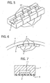
- Fig. 5 is a perspective view for illustrating how the weights and the regulatory plate are bonded in Example No. 1 of the present wheel balance weight;
- Fig. 6 is a schematic diagram for illustrating a state in which Example No. 1 of the present wheel balance weight is installed to a wheel;
- Fig. 7 is a cross-sectional view for illustrating a weight in Example No. 2 of a wheel balance weight according to the present invention;
- Fig. 8 is a cross-sectional view for illustrating a weight in Example No. 3 of a wheel balance weight according to the present invention;
- Fig. 9 is a cross-sectional view for illustrating a weight in Example No. 4 of a wheel balance weight according to the present invention;
- Fig. 10 is a cross-sectional view for illustrating a weight in Example No. 5 of a wheel balance weight according to the present invention;
- Fig. 11 is a cross-sectional view for illustrating a weight in Example No. 6 of a wheel balance weight according to the present invention;
- Fig. 12 is a perspective view for illustrating a weight in Example No. 7 of a wheel balance weight according to the present invention; and
- Fig. 13 is a cross-sectional view for illustrating a weight in Example No. 7 of a wheel balance weight according to the present invention.
- Having generally described the present invention, a further understanding can be obtained by reference to the specific preferred embodiments which are provided herein for the purpose of illustration only and not intended to limit the scope of the appended claims.
- A wheel balance weight according to the present invention comprises a plurality of weights, an adhesive sealing member and a regulatory member.
- In the present wheel balance weight, the weights cancel the unbalance in a wheel assembly when the present wheel balance weight is installed to a wheel. Since the present wheel balance weight comprises the plurality of weight, it is likely to readily conform to a curved surface of the wheel when the present wheel balance weight is installed to the wheel. For example, the present wheel weight balance effects the advantage in the following manner. Since the plurality of weights satisfy the mass, which is required for the present wheel balance weight, the weights can be downsized. As a result, the rear surface of the respective weights can substantially conform to the curved surface of the wheel.
- Note that, unless otherwise specified, the surface of the weights, which is disposed to face the central axis side of the wheel when the present wheel balance weight is installed to the wheel, is herein referred to as a "front surface", and the surface of the weights, which are disposed to face the inner peripheral surface side of the rim in the wheel when the present wheel balance is installed to the wheel, is herein referred to as a "rear surface" in the specification of the present invention.
- Since the present wheel balance weight comprises the plurality of weights, it is possible to readily adjust the entire mass of the present wheel balance weight. In other words, since the plurality of weights have a predetermined mass, respectively, it is possible to adjust the mass of the present wheel balance weight by adjusting the number of the weights.
- The adhesive sealing member is a component member, which has an adhesive surface to be fastened to the inner peripheral surface of the wheel, and which fastens the plurality of weights to the inner peripheral surface. Specifically, the plurality of weights are fastened to the wheel by bonding the adhesive surface to the inner peripheral surface of the wheel. Note that the adhesive sealing member can simply fasten the plurality of weights to the inner surface of the rim in the wheel, and that it cannot necessarily be brought into contact with the weights.
- The adhesive sealing member can preferably be an adhesive tape, which has an adhesive surface to be bonded onto the inner peripheral surface of the rim in the wheel. Since the adhesive tape is less expensive, it does not increase the material cost of the present wheel balance weight. The adhesive tape can preferably be a double-side-coated adhesive tape. When the adhesive tape is a double-side-coated adhesive tape, one of the adhesive sides of the double-side-coated adhesive tape is adhered onto the inner peripheral surface of the rim in the wheel, and the other one of the adhesive sides thereof is bonded onto the plurality of weights.
- The regulatory member is a component member, which inhibits at least two of the weights, which are disposed to neighbor with each other, from moving by a predetermined magnitude or more. When the regulatory member inhibits at least two of the neighboring weights from moving by a predetermined magnitude or more, it becomes easy to deal with the present wheel balance weight. Note that the "moving by a predetermined magnitude or more" herein means the moving other than curving the present wheel balance weight along the inner peripheral surface of the rim in the wheel. For example, the "moving by a predetermined magnitude or more" shall mean the bending between the two weights connected in succession, the twisting of the two weights connected in succession, and so on.
- The weights have means for supporting the regulatory member. Specifically, when the weights have the supporting means, the relative positions of the plurality of weights can be determined, respectively. As a result, in the manufacture of the present wheel balance weight, the plurality of weights can be assembled with ease.
- The supporting means can preferably be means, which supports the regulatory member inside the weights. Note that "the inside of the weights where the regulatory member is supported" herein means the furthermore inner portion with respect to the outer peripheral surface of the weights.
- The supporting means can be a grooved portion, which is formed in the weights and in which the regulatory member is disposed. When the supporting means is such a grooved portion, it is possible to make the weights having the supporting means at a less expensive cost. When the supporting means is the grooved portion, it is possible to readily dispose the regulatory member in the supporting means.
- The grooved portion can preferably be formed in the rear surface of the weights. Thus, the regulatory member is disposed on the rear-surface side of the weights, and accordingly the curvature radius of the regulatory member enlarges, compared with the case where the grooved portion is formed in the front-surface side of the weights. In other words, since the magnitude of deformation decreases in the regulatory member, the residual stress is less likely to generate in the regulatory member after the regulatory member is deformed. As a result, the present wheel balance weight as a whole is likely to conform to the inner surface of the rim in the wheel when it is installed to the wheel.
- The regulatory member can preferably be formed as a plate shape which has a width being equal to a width of the grooved portion. In a case where the regulatory member has a width coinciding with the width of the grooved portion, the regulatory member is supported by side surfaces of the grooved portion. Thus, it is possible to inhibit the weights from moving in the width-wise direction.
- The regulatory member can preferably be formed as a linear shape in which at least one of the outer peripheral surfaces agrees with the inner peripheral surface of the grooved portion. In a case where the regulatory member is formed as a linear shape in which at least one of the outer peripheral surfaces agrees with the inner peripheral surface of the grooved portion, the outer peripheral surface of the regulatory member is supported by the inner peripheral surface of the grooved portion when the regulatory member is disposed in the grooved portion. Hence, it is possible to inhibit the weights from moving in the width-wise direction.
- When the regulatory member is formed as a linear shape, it is preferable to form a plurality of the grooved portions. Specifically, when a plurality of the grooved portions are formed, the regulatory member inhibits the weights from moving at a plurality of positions. Thus, it is possible to inhibit the weights from twisting, for example.
- The grooved portion can preferably be narrowed at the opening. Specifically, when the grooved portion is narrowed at the opening, it is possible to inhibit the regulatory member, which is disposed in the grooved portion, from protruding out of the opening of the grooved portion. To put it differently, since the grooved portion is narrowed at the opening, the regulatory member does not project from the weights when the present wheel balance weight is installed to the wheel. Hence, it is possible to safely bend the present wheel balance weight.
- Note that the means for narrowing the opening of the grooved portion is not limited in particular. It is possible, however, to exemplify the following means. Flanged portions, which project from the weights, can be formed to the opening of the grooved portion in the weights, and the flanged portions can be deformed while disposing the regulatory member in the grooved portion.
- The supporting means can preferably be a through hole into which the regulatory member, being formed so as to penetrate through the weights, is fitted. When the supporting means is the through hole, it is possible to keep the volumetric increment of the weights minimum, volumetric increment which results from being provided with the supporting means.
- The regulatory member can preferably have a cross-sectional shape, which substantially agrees with a cross-sectional shape of the through hole. When the cross-sectional shapes of the through hole and regulatory member agree with each other substantially, the space between the regulatory member and the through hole disappears so that the weights do not deviate with each other. Moreover, when the cross-sectional shape of the through hole is formed as a circular shape, it is preferable to use a wire rod as the regulatory member.
- The through hole can preferably be formed in a plurality of quantities substantially parallelly with each other. When a plurality of the through holes are formed, it is possible to inhibit the neighboring weights from twisting with each other.
- The regulatory member can preferably be fastened to the weights. When the regulatory member is fastened to the weights, the positions of the weights themselves are determined by the regulatory member, and thereby the relative positions of the plurality of weights are determined, respectively. As a result, in the manufacture of the present wheel balance weight, the plurality of weights can be assembled with ease.
- The way how to fasten the regulatory member to the weights is not limited in particular, and can be any means as far as they are fastened. For example, it is possible to exemplify the following fastening means. A boss can be formed on the weights; through holes, into which the bosses penetrate, can be formed in the regulatory member; and then the bosses can be crimped while they penetrate through the through holes. Alternatively, the regulatory member and the bosses can be bonded integrally by welding, or the like.
- The plurality of weights can preferably be disposed at predetermined intervals linearly. When the plurality of weights are disposed at predetermined intervals linearly, the weights conform to the curved shape of the inner peripheral surface of the rim. Specifically, when the present wheel balance weight is installed to a wheel, the respective weights are disposed in the shape of a substantially curved shape. At this moment, in the neighboring two weights, the distance between the opposite front-surface-side ends is shorter than the distance between the opposite rear-surface-side ends. Accordingly, when the weights are disposed at predetermined intervals, such a distance difference can be diminished. When the present wheel balance weight is installed to a wheel, the plurality of weights, which are disposed linearly, can preferably be disposed in a peripheral direction of the wheel.
- The weights can preferably be composed of a ferrous metal. Specifically, in a case where the weights are composed of a ferrous metal, the present wheel balance weight exerts a less load to environment when it is scraped. As for a ferrous alloy for forming the weights, it is possible to use alloys whose major component is iron. For instance, it is possible to exemplify pure iron, steel, stainless steel, etc.
- The regulatory member can preferably be composed of a metal. When the regulatory member is made of a metal, it exhibits a sufficient strength for regulating the weights. Thus, it is possible to inhibit the weights from moving by a predetermined magnitude or more.
- In the present wheel balance weight, one regulatory member can preferably inhibit three or more weights from moving by a predetermined magnitude or more. Thus, it is possible to inhibit the plurality of weights from moving by a predetermined magnitude or more with one regulatory member. As a result, the number of component parts required for making the present wheel balance weight is reduced, and accordingly the cost for the component parts as well as the cost for the manufacture can be diminished.
- The regulatory member can preferably be made of a plate or a wire rod. When the regulatory member is made of a plate or a wire rod, it is possible to make the present wheel balance weight conform to an inner peripheral surface of a wheel. Specifically, when the regulatory member is made of a plate or a wire rod, it is possible to allow the weights a predetermined magnitude of movement, which is required for installing the present wheel balance weight to a wheel.
- Moreover, when the regulatory member is made of a plate or a wire rod, it is possible to dispose the plurality of weights in the extending direction of the regulatory member. Thus, it is possible to inhibit the plurality of weights from moving by a predetermined magnitude or more with one regulatory member. As a result, the number of component parts required for making the present wheel balance weight is reduced, and accordingly the cost for the component parts as well as the cost for the manufacture can be diminished.
- The present wheel balance weight can preferably be subjected to a rust-prevention treatment. Specifically, since the wheels of a vehicle are likely to contact with moisture, such as rain, etc., the unbalance in the wheels may be canceled incompletely when rust arises in the present wheel balance weight.
- In the present wheel balance weight, since the regulatory member inhibits the weights from moving by a predetermined magnitude or more, the present wheel balance weight does not bend between two weights before it is installed to a wheel. Consequently, it is easy to deal with the present wheel balance weight.
- Moreover, the present wheel balance weight comprises the plurality of weights. Accordingly, when it is installed to an inner peripheral surface of a rim in a wheel, it is likely to conform to a shape of the inner peripheral surface.
- In addition, in the present wheel balance weight, it is possible to adjust the number of weights by cutting the regulatory member and the adhesive sealing member between the plurality of weights. Hence, it is possible to give a desired mass to the present wheel balance weight.
- The present invention will be hereinafter described in detail with reference to specific examples.
- The following wheel balance weights were made as specific examples according to the present invention.
- Figs. 1 and 2 illustrate a wheel balance weight of Example No. 1 according to the present invention. The wheel balance weight of Example No. 1 is constituted by four
weights 1, aregulatory plate 2 and a double-side-coatedtape 3. The fourweights 1 are disposed at predetermined intervals. Theregulatory plate 2 is held in the fourweights 1 while it penetrates through the fourweights 1. The double-side-coatedtape 3 was disposed on a rear surface of theweights 4, and was formed integrally with theweights 1. Note that the fourweights 1 were disposed in such a state that they are separated with each other by a small interval. - The
respective weights 1 include agrooved portion 11 and aboss 12, and is a component member, which is formed as a substantially rectangular parallelepiped having a predetermined mass. The groovedportion 11 is formed as a dented shape in the rear surface of theweights 1, rear surface which contacts with the double-side-coatedtape 3 when the wheel balance weight of Example No. 1 is installed to an inner peripheral surface of a rim in a wheel. Theboss 12 projects from a bottom surface of the groovedportion 11, and has a crimpedleading end portion 13. Theleading end portion 13 is positioned flush with the rear surface of theweights 1 in which the groovedportion 11 is formed. - The
respective weights 1 are made of a ferrous rectangular parallelepiped-like material whose outer shape is 18 mm in width, 11.5 mm in length and 3 mm in thickness. The groovedportion 11 has a width of 8.2 mm, extending in opposite directions with respect to the center line of the rear surface, and a depth of 1 mm from the outermost rear surface. The groovedportion 11 is formed so as to cross therespective weights 1 in the length-wise direction. - The
boss 12 has a diameter of 4 mm, and is formed so as to protrude from the bottom surface of the groovedportion 11. Note that, as illustrated in Fig. 3, theboss 12 is formed so as to project beyond the rear surface of theweights 1 before theleading end portion 13 is formed by crimping. - As illustrated in Fig. 4, the
regulatory plate 2 is a plate-shaped component member, which is held in the groovedportion 11 formed in theweights 1. In theregulatory plate 2, there are formed throughholes 21 into which thebosses 12 penetrate when theregulatory plate 1 is held in the groovedportion 11 of theweights 1. - For example, the
regulatory plate 2 is made of an iron plate, which has a width of 8.2 mm, a length of from 11.5 to 170 mm and a thickness of 0.5 mm. Moreover, in theregulatory plate 2, there are formed throughholes 21, which have a diameter of 4 mm. - The double-side-coated
tape 3 is made of a double-side-coated adhesive tape whose opposite surfaces have an adhesive surface. Hence, the double-side-coatedtape 3 makes the wheel weight balance of Example No. 1 bond onto an inner peripheral surface of a rim in a wheel with one of the adhesive surfaces, and is bonded to theweights 1 with the other one of the adhesive surfaces. - Since the
regulatory plate 2 is fastened to theweights 1 in the wheel balance weight of Example No. 1, the plurality ofweights 1 are inhibited from moving by a predetermined magnitude or more. As a result, it is easy to deal with the wheel balance weight of Example No. 1 before it is installed to a wheel. - The wheel balance weight of Example No. 1 could be manufactured in the following manner. First, the
weights 1 and theregulatory plate 2 were formed. Then, theregulatory plate 2 was fitted into thegrooved portions 11 of theweights 1. Finally, the double-side-coatedtape 3 was bonded onto the rear surfaces of theweights 1. - For instance, the
weights 1 were first formed by such means as pressing an iron plate, forging a wire rod, and the like. Note that, in the resultingweights 1, thebosses 12 were formed so as to project beyond the rear surfaces of therespective weights 1. In Fig. 3, there is illustrated how the leading end of theboss 12 projected beyond the rear surface of theweights 1. - The
regulatory plate 2 was manufactured by pressing an iron plate. In Fig. 4, there is illustrated the resultantregulatory plate 2. - Subsequently, the
regulatory plate 2 was fitted into thegrooved portions 11 of theweights 1. In the operation, thebosses 12 penetrated through the throughholes 21 of theregulatory plates 2. Note that theregulatory plate 2 was fitted into thegrooved portions 11 so as to bring one of the opposite surfaces into contact with the bottom surfaces of thegrooved portions 11. - Thereafter, the leading ends of the
bosses 12, which penetrated through the throughholes 21 and which projected beyond the rear surfaces of theweights 1, were crimped so that the surfaces of theleading end portions 13 were flush with the rear surfaces of theweights 1. Since theleading end portions 13 were formed larger than the throughholes 21 in terms of the diameter, theregulatory plate 2 was fastened to theweights 1. In Fig. 5, there is illustrated how theregulatory plate 1 was fastened to theweights 1. - After the wheel balance weight of Example No. 1, in which the
regulatory plate 2 was fastened to theweights 1, was subjected to a plating treatment, one of the adhesive surfaces of the double-side-coatedtape 3 was bonded onto the rear surfaces of theweights 1 as well as theleading end portions 13 of thebosses 12. The wheel balance weight of Example No. 1 was thus manufactured. - The wheel balance weight of Example No. 7 was actually installed to a wheel by the following procedure. In Fig. 6, there is illustrated how the wheel balance weight was installed onto an inner peripheral surface of a rim in a
wheel 4. - First, the mass of the wheel balance weight of Example No. 1 was adjusted to a mass, which is desirable for canceling the unbalance in the
wheel 4, by cutting theregulatory plate 2 and the double-side-coatedtape 3 between the neighboringweights - Subsequently, the wheel weight balance of Example No. 1 was installed to the
wheel 4 in the following manner. The adhesive surface of the double-side-coatedtape 3 of the wheel balance weight of Example No. 1 was exposed. The exposed adhesive surface was applied onto a predetermined position on an inner peripheral surface of a rim in thewheel 4. In the installation, theweights wheel 4 so that they were arranged in a peripheral direction of thewheel 4. - Note that, in the wheel balance weight of Example No. 1, the
weights wheel 4 and thereby theregulatory plate 2 was deformed to a curved shape, which substantially coincides with a shape of the inner peripheral surface of thewheel 4. In the mean time, since the fourweights 1 were connected to theregulatory plate 2 with intervals provided therebetween, the distance between the opposite front-surface-side ends of the neighboringweights - As a result, the wheel balance weight of Example No. 1 could be installed in such a state that it conformed to the curved inner peripheral surface of the rim in the
wheel 4. - A wheel balance weight of Example No. 2 according to the present invention comprises
weights 1. Fig. 7 illustrates a cross section of theweights 1. - The wheel balance weight of Example No. 2 is constituted by a plurality of the
weights 1, a strip-shapedregulatory plate 2 and a double-side-coatedtape 3. Theweights 1 have a groovedportion 11, which is formed in the rear surface. The strip-shapedregulatory plate 2 is disposed in thegrooved portions 11. The double-side-coatedtape 3 is adhered onto theweights 1 and theregulatory plate 2. Note that, in the wheel balance weight of Example No. 2, theregulatory plate 2 is simply disposed in thegrooved portions 11 of theweights 1 and is simply brought into contact with theweights 1. Thus, the strip-shapedregulatory plate 2 and theweights 1 are not bonded with each other directly. - Except that the
bosses 12 are not formed in thegrooved portions 11, theweights 1 in the wheel balance weight of Example No. 2 are identical with theweights 1 in the wheel balance of Example No. 1. - Except that the through
holes 21 are not formed, theregulatory plate 2 is a strip-shaped metallic plate, which is identical with theregulatory plate 2 in the wheel balance weight of Example No. 1. - As for the double-side-coated
tape 3, a double-side-coated tape is employed which is the same as the double-side-coatedtape 3 in the wheel balance weight of Example No. 1. - In the wheel balance weight of Example No. 2, since the
regulatory plate 2 is fixed in thegrooved portions 11 of theweights 1 by the double-side-coatedtape 3, the plurality of theweights 1 are inhibited from moving by a predetermined magnitude or more. Therefore, it is easy to deal with the wheel balance weight of Example No. 2 before it is installed to a wheel. - Moreover, in the wheel balance weight of Example No. 2, since the
weights 1 and theregulatory plate 2 are not bonded integrally, the wheel balance weight effects an advantage in that it can reduce the cost required for manufacturing itself. - A wheel balance weight of Example No. 3 according to the present invention comprises
weights 1. Fig. 8 illustrates a cross section of theweights 1. - The wheel balance weight of Example No. 3 is constituted by a plurality of the
weights 1, a strip-shapedregulatory plate 2 and a double-side-coatedtape 3. Theweights 1 have a groovedportion 11, which is formed in the rear surface. The strip-shapedregulatory plate 2 is bonded to the bottom surface of thegrooved portions 11. The double-side-coatedtape 3 is adhered onto the rear surfaces of theweights 1. - Specifically, in the wheel balance weight of Example No. 3, the
regulatory plate 2 is bonded to the bottom surfaces of theweights 1. Moreover, theregulatory plate 2 is not bonded to the double-side-coatedtape 3. - As for the
weights 1, theregulatory plate 2 and the double-side-coatedtape 3, the component members are identical with those used in Example No. 2. - Moreover, in the wheel balance weight of Example No. 3, the
weights 1 and theregulatory plate 2 are bonded by spot welding. Note that the means for bonding theweights 1 and theregulatory member 2 is not limited in particular as far as the means can bond them together. For example, theweights 1 and theregulatory plate 2 can be bonded by an adhesive, a double-side-coated tape, or the like. - In the wheel balance weight of Example No. 3, since the
regulatory plate 2 is fastened to theweights 1, the plurality of theweights 1 are inhibited from moving by a predetermined magnitude or more. Therefore, it is easy to deal with the wheel balance weight of Example No. 3 before it is installed to a wheel. - In addition, in the wheel balance weight of Example No. 3, since the
weights 1 and theregulatory plate 2 are bonded by spot welding, they can be bonded at a less expensive cost. Hence, the wheel balance weight effects an advantage in that it can reduce the cost required for manufacturing itself. - A wheel balance weight of Example No. 4 according to the present invention comprises
weights 1. Fig. 9 illustrates a cross section of theweights 1. - The wheel balance weight of Example No. 4 is constituted by a plurality of the
weights 1, a strip-shapedregulatory plate 2 and a double-side-coatedtape 3. Theweights 1 are formed substantially as a rectangular parallelepiped. The strip-shapedregulatory plate 2 is bonded to the rear surfaces of theweights 1. The double-side-coatedtape 3 is adhered onto the rear surface of the strip-shapedregulatory plate 2. - The
weight 1 is composed of a substantially rectangular parallelepiped-like metallic material whose outer contour has a size of 20 mm in width, 11.5 mm in length and 3 mm in thickness. - The
regulatory plate 2 is composed of an iron plate, which has a size of 20 mm in width, from 11.5 to 170 mm in length and 0.5 mm in thickness. - The double-side-coated
tape 3 has a strip shape, which agrees with the rear surface of theregulatory plate 2. As for the double-side-coatedplate 3, a double-side-coated tape is used which is the same as the one used in Example No. 1. - Moreover, in the wheel balance weight of Example No. 4, the
weights 1 and theregulatory plate 2 are bonded by spot welding. Note that the means for bonding theweights 1 and theregulatory member 2 is not limited in particular as far as the means can bond them together. For example, theweights 1 and theregulatory plate 2 can be bonded by an adhesive, a double-side-coated tape, or the like. - In the wheel balance weight of Example No. 4, since the
regulatory plate 2 is fastened to theweights 1, the plurality of theweights 1 are inhibited from moving by a predetermined magnitude or more. Therefore, it is easy to deal with the wheel balance weight of Example No. 4 before it is installed to a wheel. - In addition, in the wheel balance weight of Example No. 4, since the
weights 1 and theregulatory plate 2 are bonded by spot welding, they can be bonded at a less expensive cost. Hence, the wheel balance weight effects an advantage in that it can reduce the cost required for manufacturing itself. - A wheel balance weight of Example No. 5 according to the present invention comprises
weights 1. Fig. 10 illustrates a cross section of theweights 1. - The wheel balance weight of Example No. 5 is constituted by a plurality of the
weights 1,regulatory wires tape 3. Theweights 1 are formed substantially as a rectangular parallelepiped, and has two throughholes regulatory wires holes tape 3 is adhered onto the rear surfaces of theweights 1. - Specifically, the wheel balance weight of Example No. 5 is a wheel weight balance in which the through
holes grooved portions 11 in theweights 1 of Example Nos. 1 through 4, and in which theregulatory wires regulatory plate 2 of Example Nos. 1 through 4. - The
weights 1 are made of a substantially rectangular parallelepiped-like iron material whose outer contour has a size of 18 mm in width, 11.5 mm in length and 3 mm in thickness. The through holes 15, 15 having a diameter of 2 mm are formed to penetrate through theweights 1 in the length-wise direction of theweights 1. The two throughholes weights 1, respectively, and so that their centers are separated at an interval of 10 mm. - The
regulatory wires - The double-side-coated
tape 3 has a strip shape, which agrees with the rear surfaces of theweights 1. As for the double-side-coatedplate 3, a double-side-coated tape is used which is the same as the one used in Example No. 1. - In the wheel balance weight of Example No. 5, since the two
regulatory wires weights 1, the plurality ofweights 1 are inhibited from moving by a predetermined magnitude or more. Therefore, it is easy to deal with the wheel balance weight of Example No. 5 before it is installed to a wheel. - A wheel balance weight of Example No. 6 according to the present invention comprises
weights 1. Fig. 11 illustrates a cross section of theweights 1. - The wheel balance weight of Example No. 6 is constituted by a plurality of the
weights 1,regulatory wires tape 3. Theweights 1 are formed substantially as a rectangular parallelepiped, and has two groovedportions grooved portions flanged portions regulatory wires grooved portions flanged portions tape 3 is adhered onto the rear surfaces of theweights 1. - Specifically, except that the plurality of
weights 1 are used in which thegrooved portions holes - The
weights 1 were made of a substantially rectangular parallelepiped-like iron material whose outer contour has a size of 18 mm in width, 11.5 mm in length and 3 mm in thickness. On the rear sides, as illustrated in Fig. 12, there are formed thegrooved portions flanged portions flanged portions grooved portions weights 1. Thegrooved portions weights 1. For instance, thegrooved portions weights 1. Moreover, the bottom surfaces of thegrooved portions flanged portions grooved portions weights 1 by a height of 1 mm. - The
grooved portions - The
regulatory wires - The double-side-coated
tape 3 has a strip shape, which agrees with the rear surfaces of theweights 1. As for the double-side-coatedplate 3, a double-side-coated tape is used which is the same as the one used in Example No. 1. - In the wheel balance weight of Example No. 6, since the two
regulatory wires grooved portions weights 1, theweights 1 are inhibited from moving by a predetermined magnitude or more. Therefore, it is easy to deal with the wheel balance weight of Example No. 6 before it is installed to a wheel. - The wheel balance weight of Example No. 6 could be manufactured in the following manner. First, the
weights 1 were formed. Then, theflanged portions regulatory wires grooved portions weights 1. Finally, the double-side-coatedtape 3 was bonded onto the rear surfaces of theweights 1. - For instance, the
weights 1 were first formed by such means as pressing an iron plate, forging a wire rod, or the like. Note that, in the resultingweights 1, theflanged portions respective weights 1. In Fig. 12, there is illustrated how theflanged portions weights 1. - The
regulatory wires grooved portions weights 1. At this moment, theregulatory wires grooved portions - Subsequently, the
flanged portions grooved portions grooved portions weights 1. When theflanged portions grooved portions flanged portions regulatory wires grooved portions regulatory wires grooved portions weights 1. - After the wheel balance weight of Example No. 6, in which the
regulatory wires weights 1, was subjected to a plating treatment, one of the adhesive surfaces of the double-side-coatedtape 3 was bonded onto the rear surfaces of theweights 1. The wheel balance weight of Example No. 6 was thus manufactured. - A wheel balance weight of Example No. 7 according to the present invention comprises
weights 1. Fig. 13 illustrates a cross section of theweights 1. - The wheel balance weight of Example No. 6 is constituted by a plurality of the
weights 1, aregulatory wire 25 and a double-side-coatedtape 3. In theweights 1, there are formed agrooved portion 16 in the rear surface. The opening of the groovedportion 16 is closed by crimpingflanged portions regulatory wire 25 is fixed in the groovedportion 16. The double-side-coatedtape 3 is adhered onto the rear surfaces of theweights 1. - Specifically, except that one
grooved portion 16 is formed in theweights 1 in the middle thereof and in the width-wise direction thereof, the wheel balance weight of Example No. 7 is identical with that of Example No. 6. - In the wheel balance weight of Example No. 7, since the
regulatory wire 25 is fixed in thegrooved portions 16 of the plurality ofweights 1, theweights 1 are inhibited from moving by a predetermined magnitude or more. Therefore, it is easy to deal with the wheel balance weight of Example No. 7 before it is installed to a wheel. Moreover, since oneregulatory wire 25 is placed in theweights 1, it is possible to reduce the man-hour requirement for installing theregulatory wire 25 to theweights 1. Accordingly, it is possible to keep the cost for manufacturing the wheel balance weight of Example No. 7 from going up. - A wheel balance weight includes a plurality of weights, an adhesive sealing member and a regulatory member. The adhesive sealing member fastens the plurality of weights onto an inner peripheral surface of a rim in a wheel, and has an adhesive surface to be bonded to the inner peripheral surface. The regulatory member inhibits at least two of the plurality of weights, being disposed to neighbor with each other, from moving by a predetermined magnitude or more. Hence, the wheel balance weight deal can be dealt with readily before it is installed to the wheel, is likely to conform to the inner surface, and can have a desired mass with ease.
Claims (8)
- A wheel balance weight, comprising:a plurality of weights (1);an adhesive sealing member (3), having an adhesive surface to be bonded to an inner peripheral surface of a rim in a wheel, for fastening the plurality of weights (1) onto the inner peripheral surface;characterized in that
a regulatory member (2; 25) is supported by supporting means (11, 12, 13; 15) provided with at least two of said weights (1), and
that the regulatory member (2; 25) inhibits at least two of said weights (1), being disposed to neighbor with each other, from moving by a predetermined magnitude or more. - The wheel balance weight according to claim 1, wherein the supporting means (11, 12, 13; 15)) is a grooved portion (11), which is formed in at least two of said weights (1) and in which said regulatory member (2; 25) is disposed.
- The wheel balance weight according to claim 2, wherein said regulatory member (2; 25) is formed as a plate shape, which has a width being substantially equal to a width of the grooved portion (11).
- The wheel balance weight according to claim 2, wherein at least a part of an outer peripheral surface of said regulatory member (2; 25) is formed as a linear shape, which substantially agrees with an inner peripheral surface of the grooved portion (11).
- The wheel balance weight according to claim 1, wherein the supporting means (11, 12, 13; 15) is a through hole (15), which is formed through at least two of said weights (1) and into which said regulatory member (25) is fitted.
- The wheel balance weight according to claim 5, wherein said regulatory surface (25) has a cross-sectional shape, which substantially agrees with a cross-sectional shape of the through hole (15).
- The wheel balance weight according to claim 1, wherein said regulatory member (2; 25) is fastened to at least two of said weights (1).
- The wheel balance weight according to claim 1, wherein said plurality of weights (1) are disposed at predetermined intervals linearly.
Applications Claiming Priority (2)
| Application Number | Priority Date | Filing Date | Title |
|---|---|---|---|
| JP2001104338 | 2001-04-03 | ||
| JP2001104338A JP2002295592A (en) | 2001-04-03 | 2001-04-03 | Wheel balance weight |
Publications (3)
| Publication Number | Publication Date |
|---|---|
| EP1248014A2 EP1248014A2 (en) | 2002-10-09 |
| EP1248014A3 EP1248014A3 (en) | 2003-04-02 |
| EP1248014B1 true EP1248014B1 (en) | 2006-05-24 |
Family
ID=18957211
Family Applications (1)
| Application Number | Title | Priority Date | Filing Date |
|---|---|---|---|
| EP01126675A Expired - Lifetime EP1248014B1 (en) | 2001-04-03 | 2001-11-08 | Wheel balance weight |
Country Status (4)
| Country | Link |
|---|---|
| US (1) | US6592188B2 (en) |
| EP (1) | EP1248014B1 (en) |
| JP (1) | JP2002295592A (en) |
| DE (1) | DE60119888T2 (en) |
Cited By (1)
| Publication number | Priority date | Publication date | Assignee | Title |
|---|---|---|---|---|
| EP2913555A1 (en) | 2014-02-26 | 2015-09-02 | WEGMANN automotive GmbH & Co. KG | Linked clip-on balancing weights for vehicles |
Families Citing this family (24)
| Publication number | Priority date | Publication date | Assignee | Title |
|---|---|---|---|---|
| USD770925S1 (en) * | 1920-10-06 | 2016-11-08 | Wegmann Automotive Gmbh & Co. Kg | Tire balancing weight |
| WO2004090495A2 (en) * | 2003-04-11 | 2004-10-21 | Franken Industrie Werke Ernst Stenz Gmbh & Co.Kg | Balancing weight for vehicle wheels, comprising a concavely or convexly curved contact face, and method for the production thereof |
| DE20307952U1 (en) * | 2003-05-21 | 2004-03-04 | Bettchen, Uwe | Vehicle-Balancing weight track |
| US7044561B2 (en) * | 2003-11-18 | 2006-05-16 | Halko Manufacturing Co. | Adhesive wheel balancing weights having a serrated backing strip |
| US20060273652A1 (en) * | 2005-05-11 | 2006-12-07 | Conceptual Plastic Creations, Llc | Balance weight |
| FR2909151B1 (en) * | 2006-04-07 | 2012-02-10 | Zenith Prec | BALANCING MASS DEVICE |
| CN101689090A (en) * | 2007-06-28 | 2010-03-31 | 京瓷株式会社 | Touch panel, and touch panel type display device |
| US20090243370A1 (en) * | 2008-03-31 | 2009-10-01 | Hennessy Industries, Inc. | Wheel weight |
| US20120067162A1 (en) * | 2010-09-17 | 2012-03-22 | Steven Kollmann | Steering Wheel Armature Weight |
| US9004611B2 (en) | 2011-12-22 | 2015-04-14 | Wegmann Automotive Usa Inc. | Stamped wheel balancing weight |
| EP2642155A1 (en) * | 2012-03-20 | 2013-09-25 | WEGMANN automotive GmbH & Co. KG | Magazine for balancing weights |
| US10024387B2 (en) | 2012-03-21 | 2018-07-17 | Wegman Automotive USA Inc. | Wheel balancing weight and method of manufacture |
| CA2992895C (en) * | 2012-03-21 | 2018-09-25 | Wegmann, Automotive Usa Inc. | Wheel balancing weight and method of manufacture |
| KR101389326B1 (en) * | 2014-01-22 | 2014-04-25 | 백인태 | Wheel balance weight for car and making method the same |
| USD754012S1 (en) * | 2014-01-30 | 2016-04-19 | Wegmann Automotive Gmbh & Co. Kg | Tire balancers (weights) |
| US20160271460A1 (en) * | 2014-08-08 | 2016-09-22 | Dunlop Sports Co., Ltd. | Patterned weighted tape for use on golf club |
| EP2988018A1 (en) | 2014-08-21 | 2016-02-24 | WEGMANN automotive GmbH & Co. KG | Self-adhesive balancing weight for a vehicle wheel |
| USD770926S1 (en) * | 2014-10-06 | 2016-11-08 | Wegmann Automotive Gmbh & Co. Kg | Tire balancing weight |
| USD770924S1 (en) * | 2014-10-06 | 2016-11-08 | Wegmann Automotive Gmbh & Co. Kg | Tire balancing weight |
| USD770922S1 (en) * | 2014-10-06 | 2016-11-08 | Wegmann Automotive Gmbh & Co. Kg | Tire balancing weight |
| USD770923S1 (en) * | 2014-10-06 | 2016-11-08 | Wegmann Automotive Gmbh & Co. Kg | Tire balancing weights |
| RU2720752C2 (en) * | 2016-02-19 | 2020-05-13 | Вегманн Отомоутив Гмбх Унд Ко. Кг | Self-adhesive balancing weight for wheel vehicle |
| KR101741411B1 (en) * | 2017-03-14 | 2017-05-31 | 주식회사 에스지에스이엔지 | Wheel balance weight |
| KR102545652B1 (en) * | 2020-11-27 | 2023-06-20 | (주)성우오토테크 | Wheel balance weight with improved adhesive strength |
Family Cites Families (11)
| Publication number | Priority date | Publication date | Assignee | Title |
|---|---|---|---|---|
| US1692145A (en) * | 1926-01-21 | 1928-11-20 | Chrysler Corp | Means for balancing pneumatic tires |
| FR1197125A (en) | 1958-02-21 | 1959-11-27 | Device for maintaining a motor vehicle wheel balancing mass | |
| US3960409A (en) | 1974-11-25 | 1976-06-01 | Perfect Equipment Corporation | Wheel balancing weight |
| US4379596A (en) * | 1979-09-14 | 1983-04-12 | Speed Clip Manufacturing Corp. | Superpositioned vehicle wheel balance weights and method |
| JPH0355185U (en) * | 1989-09-29 | 1991-05-28 | ||
| DE9116322U1 (en) | 1990-06-26 | 1992-07-09 | Nuovakautschuk GmbH, 8499 Traitsching | Counterweight for balancing rotating components |
| HU223041B1 (en) | 1997-06-27 | 2004-03-01 | István Polyvás | Wheel-weight for balancing vehicle wheel |
| GB9808981D0 (en) | 1998-04-27 | 1998-06-24 | Itri Ltd | Tin alloy wheel balancing weights |
| JP2000274490A (en) * | 1999-03-25 | 2000-10-03 | Yamate Kogyo Kk | Balance weight |
| US6260929B1 (en) | 1999-07-07 | 2001-07-17 | Topy Koygo Kabushiki Kaisha | Wheel balance weight and a method of manufacturing the same |
| DE10008393A1 (en) * | 2000-02-23 | 2001-08-30 | Schenck Rotec Gmbh | String of linked metallic balance weights totally enclosed in plastic coating |
-
2001
- 2001-04-03 JP JP2001104338A patent/JP2002295592A/en active Pending
- 2001-10-24 US US09/983,482 patent/US6592188B2/en not_active Expired - Lifetime
- 2001-11-08 DE DE60119888T patent/DE60119888T2/en not_active Expired - Fee Related
- 2001-11-08 EP EP01126675A patent/EP1248014B1/en not_active Expired - Lifetime
Cited By (2)
| Publication number | Priority date | Publication date | Assignee | Title |
|---|---|---|---|---|
| EP2913555A1 (en) | 2014-02-26 | 2015-09-02 | WEGMANN automotive GmbH & Co. KG | Linked clip-on balancing weights for vehicles |
| WO2015128349A1 (en) * | 2014-02-26 | 2015-09-03 | Wegmann Automotive Gmbh & Co. Kg | Linked clip-on balancing weights for vehicles |
Also Published As
| Publication number | Publication date |
|---|---|
| US6592188B2 (en) | 2003-07-15 |
| US20020140281A1 (en) | 2002-10-03 |
| DE60119888D1 (en) | 2006-06-29 |
| DE60119888T2 (en) | 2006-11-16 |
| EP1248014A2 (en) | 2002-10-09 |
| EP1248014A3 (en) | 2003-04-02 |
| JP2002295592A (en) | 2002-10-09 |
Similar Documents
| Publication | Publication Date | Title |
|---|---|---|
| EP1248014B1 (en) | Wheel balance weight | |
| EP1355084B1 (en) | Wheel balance weight and process for manufacturing the same | |
| US6238005B1 (en) | Wheel balance weight | |
| US7871092B2 (en) | Structural motor vehicle axle system assembled by structural bonding | |
| EP2039538B1 (en) | Vehicle wheel with pressure sensor | |
| US6659567B2 (en) | Wheel balance weight and process for manufacturing the same | |
| US7249804B2 (en) | Wheel balancing weight with half-clip | |
| FI99157C (en) | Balancing arrangement for rotating member | |
| EP2271856B1 (en) | Wheel balance clip | |
| JP2003002025A (en) | Suspension arm structure | |
| EP1927784A1 (en) | Wheel balancing device | |
| JP3503007B2 (en) | Wheel balance weight and method of manufacturing the same | |
| JP4149900B2 (en) | Wheel balance weight | |
| US20100117442A1 (en) | Wheel balance clip | |
| JP2005291262A (en) | Wheel balance weight | |
| JPH08128485A (en) | Installation ring for hydraulic buffer and manufacture thereof | |
| JP3922666B2 (en) | Wheel balance weight | |
| US20080088173A1 (en) | Wheel balancing device | |
| KR102268505B1 (en) | Power transmission shaft and manufacturing method thereof | |
| JP2002372103A (en) | Wheel balance weight | |
| JP3949099B2 (en) | wheel | |
| JPH11280845A (en) | Wheel balance weight | |
| JP2002061714A (en) | Wheel balance weight | |
| EP0175846A2 (en) | A wheel balance weight | |
| JPH07315025A (en) | Arm for suspension and its manufacture |
Legal Events
| Date | Code | Title | Description |
|---|---|---|---|
| PUAI | Public reference made under article 153(3) epc to a published international application that has entered the european phase |
Free format text: ORIGINAL CODE: 0009012 |
|
| 17P | Request for examination filed |
Effective date: 20011108 |
|
| AK | Designated contracting states |
Kind code of ref document: A2 Designated state(s): AT BE CH CY DE DK ES FI FR GB GR IE IT LI LU MC NL PT SE TR |
|
| AX | Request for extension of the european patent |
Free format text: AL;LT;LV;MK;RO;SI |
|
| PUAL | Search report despatched |
Free format text: ORIGINAL CODE: 0009013 |
|
| AK | Designated contracting states |
Kind code of ref document: A3 Designated state(s): AT BE CH CY DE DK ES FI FR GB GR IE IT LI LU MC NL PT SE TR |
|
| AX | Request for extension of the european patent |
Extension state: AL LT LV MK RO SI |
|
| AKX | Designation fees paid |
Designated state(s): DE FR GB GR IT SE |
|
| 17Q | First examination report despatched |
Effective date: 20040116 |
|
| GRAP | Despatch of communication of intention to grant a patent |
Free format text: ORIGINAL CODE: EPIDOSNIGR1 |
|
| GRAS | Grant fee paid |
Free format text: ORIGINAL CODE: EPIDOSNIGR3 |
|
| GRAA | (expected) grant |
Free format text: ORIGINAL CODE: 0009210 |
|
| AK | Designated contracting states |
Kind code of ref document: B1 Designated state(s): DE FR GB GR IT SE |
|
| PG25 | Lapsed in a contracting state [announced via postgrant information from national office to epo] |
Ref country code: IT Free format text: LAPSE BECAUSE OF FAILURE TO SUBMIT A TRANSLATION OF THE DESCRIPTION OR TO PAY THE FEE WITHIN THE PRESCRIBED TIME-LIMIT;WARNING: LAPSES OF ITALIAN PATENTS WITH EFFECTIVE DATE BEFORE 2007 MAY HAVE OCCURRED AT ANY TIME BEFORE 2007. THE CORRECT EFFECTIVE DATE MAY BE DIFFERENT FROM THE ONE RECORDED. Effective date: 20060524 |
|
| REG | Reference to a national code |
Ref country code: GB Ref legal event code: FG4D |
|
| RIN1 | Information on inventor provided before grant (corrected) |
Inventor name: YAMAGUCHI, YUTAKA,C/O TOHO KOGYO CO., LTD. |
|
| REF | Corresponds to: |
Ref document number: 60119888 Country of ref document: DE Date of ref document: 20060629 Kind code of ref document: P |
|
| REG | Reference to a national code |
Ref country code: SE Ref legal event code: TRGR |
|
| REG | Reference to a national code |
Ref country code: GR Ref legal event code: EP Ref document number: 20060402767 Country of ref document: GR |
|
| PGFP | Annual fee paid to national office [announced via postgrant information from national office to epo] |
Ref country code: FR Payment date: 20061117 Year of fee payment: 6 |
|
| PGFP | Annual fee paid to national office [announced via postgrant information from national office to epo] |
Ref country code: SE Payment date: 20061123 Year of fee payment: 6 Ref country code: GB Payment date: 20061123 Year of fee payment: 6 |
|
| PGFP | Annual fee paid to national office [announced via postgrant information from national office to epo] |
Ref country code: GR Payment date: 20061129 Year of fee payment: 6 |
|
| PGFP | Annual fee paid to national office [announced via postgrant information from national office to epo] |
Ref country code: IT Payment date: 20061130 Year of fee payment: 6 |
|
| ET | Fr: translation filed | ||
| PGFP | Annual fee paid to national office [announced via postgrant information from national office to epo] |
Ref country code: DE Payment date: 20061229 Year of fee payment: 6 |
|
| PLBE | No opposition filed within time limit |
Free format text: ORIGINAL CODE: 0009261 |
|
| STAA | Information on the status of an ep patent application or granted ep patent |
Free format text: STATUS: NO OPPOSITION FILED WITHIN TIME LIMIT |
|
| 26N | No opposition filed |
Effective date: 20070227 |
|
| EUG | Se: european patent has lapsed | ||
| GBPC | Gb: european patent ceased through non-payment of renewal fee |
Effective date: 20071108 |
|
| PG25 | Lapsed in a contracting state [announced via postgrant information from national office to epo] |
Ref country code: GR Free format text: LAPSE BECAUSE OF NON-PAYMENT OF DUE FEES Effective date: 20060825 Ref country code: DE Free format text: LAPSE BECAUSE OF NON-PAYMENT OF DUE FEES Effective date: 20080603 Ref country code: SE Free format text: LAPSE BECAUSE OF NON-PAYMENT OF DUE FEES Effective date: 20071109 |
|
| REG | Reference to a national code |
Ref country code: FR Ref legal event code: ST Effective date: 20080930 |
|
| PG25 | Lapsed in a contracting state [announced via postgrant information from national office to epo] |
Ref country code: GB Free format text: LAPSE BECAUSE OF NON-PAYMENT OF DUE FEES Effective date: 20071108 |
|
| PG25 | Lapsed in a contracting state [announced via postgrant information from national office to epo] |
Ref country code: FR Free format text: LAPSE BECAUSE OF NON-PAYMENT OF DUE FEES Effective date: 20071130 |
|
| PG25 | Lapsed in a contracting state [announced via postgrant information from national office to epo] |
Ref country code: IT Free format text: LAPSE BECAUSE OF NON-PAYMENT OF DUE FEES Effective date: 20071108 |