WO2019003561A1 - 回転電機の固定子、及び回転電機 - Google Patents
回転電機の固定子、及び回転電機 Download PDFInfo
- Publication number
- WO2019003561A1 WO2019003561A1 PCT/JP2018/014877 JP2018014877W WO2019003561A1 WO 2019003561 A1 WO2019003561 A1 WO 2019003561A1 JP 2018014877 W JP2018014877 W JP 2018014877W WO 2019003561 A1 WO2019003561 A1 WO 2019003561A1
- Authority
- WO
- WIPO (PCT)
- Prior art keywords
- stator
- insulator
- coil
- electric machine
- rotary electric
- Prior art date
- Legal status (The legal status is an assumption and is not a legal conclusion. Google has not performed a legal analysis and makes no representation as to the accuracy of the status listed.)
- Ceased
Links
Images








Classifications
-
- H—ELECTRICITY
- H02—GENERATION; CONVERSION OR DISTRIBUTION OF ELECTRIC POWER
- H02K—DYNAMO-ELECTRIC MACHINES
- H02K3/00—Details of windings
- H02K3/32—Windings characterised by the shape, form or construction of the insulation
- H02K3/38—Windings characterised by the shape, form or construction of the insulation around winding heads, equalising connectors, or connections thereto
-
- H—ELECTRICITY
- H02—GENERATION; CONVERSION OR DISTRIBUTION OF ELECTRIC POWER
- H02K—DYNAMO-ELECTRIC MACHINES
- H02K3/00—Details of windings
- H02K3/32—Windings characterised by the shape, form or construction of the insulation
-
- H—ELECTRICITY
- H02—GENERATION; CONVERSION OR DISTRIBUTION OF ELECTRIC POWER
- H02K—DYNAMO-ELECTRIC MACHINES
- H02K1/00—Details of the magnetic circuit
- H02K1/06—Details of the magnetic circuit characterised by the shape, form or construction
- H02K1/12—Stationary parts of the magnetic circuit
- H02K1/16—Stator cores with slots for windings
-
- H—ELECTRICITY
- H02—GENERATION; CONVERSION OR DISTRIBUTION OF ELECTRIC POWER
- H02K—DYNAMO-ELECTRIC MACHINES
- H02K2203/00—Specific aspects not provided for in the other groups of this subclass relating to the windings
- H02K2203/06—Machines characterised by the wiring leads, i.e. conducting wires for connecting the winding terminations
Definitions
- the present invention relates to a stator and a rotary electric machine using the same, and more particularly to a rotary electric machine that generates a torque for traveling of an automobile or generates electric power at the time of braking.
- a rotating magnetic field is generated by supplying alternating current power to the stator coil, and the rotor is rotated by the rotating magnetic field.
- mechanical energy applied to the rotor can be converted to electrical energy and AC power can be output from the coil.
- the rotary electric machine operates as a motor or a generator.
- a stator according to the present invention or a rotary electric machine using the same comprises: a stator core having a plurality of slots aligned in a circumferential direction; and a plurality of segments inserted in the slots and formed into a substantially U shape A coil and an insulator disposed between the plurality of segment coils, the insulator has a portion in which a portion of the insulator is formed thicker than other portions of the insulator.
- the insulation reliability of the rotating electrical machine can be improved.
- FIG. 2 is an overall perspective view of a stator 20.
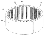
- FIG. 7 is an overall perspective view of a stator core 132.
- FIG. 6 is a cross sectional view showing a cross section of a rotor 11 and a stator core 132.
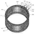
- FIG. 7 is an overall perspective view showing a stator coil 60. It is a conceptual diagram which shows the connection state of the stator coil 60.
- FIG. FIG. 6 is a conceptual diagram illustrating segment conductors 28 that constitute a stator coil 60.
- FIG. 6 is a conceptual diagram illustrating segment conductors 28 that constitute a stator coil 60. It is a perspective view which shows U-phase coil 60U which is one phase of the stator coil 60 shown in FIG.
- FIG. 18 is a view showing an end 28E1 to an end 28E4 after bending of the segment conductor 28 in the welding side coil end 62.
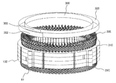
- FIG. 16 is a perspective view of the welding side coil end 62 before inserting the insulator 300 having the overlapping portion 302 between the segment conductors 28.
- FIG. 18 is a perspective view of the welding side coil end 62 just before inserting the insulator 300 having the overlapping portion 302 between the segment conductors 28.
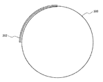
- the insulator 300 seen from the rotating shaft direction of the rotary electric machine 10 is shown.
- the insulator 300 seen from the rotating shaft direction of the rotary electric machine 10 is shown.
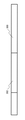
- the insulator 300 which concerns on other embodiment seen from the rotating shaft direction of the rotary electric machine 10 is shown. It is a side view of insulator 300 before bending overlapping part 302 concerning other embodiments. It is a side view of insulator 300 after bending overlap part 302 concerning other embodiments.
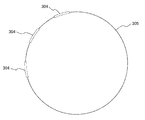
- the insulator 300 which concerns on other embodiment seen from the rotating shaft direction of the rotary electric machine 10 is shown.
- BRIEF DESCRIPTION OF THE DRAWINGS The schematic structure of the hybrid type electric vehicle carrying the rotary electric machine 10 which concerns on this embodiment is shown.
- the rotary electric machine 10 in the present embodiment is a rotary electric machine suitable to be used for traveling a car.
- a so-called electric vehicle using the rotating electrical machine 10 a hybrid type electric vehicle (HEV) including both the engine ENG and the rotating electrical machine 10, and a pure vehicle traveling only by the rotating electrical machine 10 without using the engine ENG.
- HEV hybrid type electric vehicle
- EV electric car Since the rotary electric machine described below can be used for both types, it will be described based on the rotary electric machine used as a representative of a hybrid type car.
- the “axial direction” refers to the direction along the rotation axis of the rotating electrical machine.
- the circumferential direction refers to the direction along the rotation direction of the rotating electrical machine.
- the “radial direction” refers to a radial direction (radial direction) around the rotation axis of the rotating electrical machine.
- the “inner circumferential side” refers to the radially inner side (inner diameter side), and the “outer circumferential side” refers to the opposite direction, that is, the radially outer side (outer diameter side).
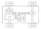
- FIG. 18 a schematic configuration of a vehicle on which the rotating electrical machine is mounted will be described.
- An engine ENG and a rotating electrical machine 10 are provided as main powers on the front wheel side.
- the power generated by the engine ENG and the rotary electric machine 10 is shifted by the transmission TR, and the power is transmitted to the front-wheel drive wheels FW.
- the rotary electric machine 10 disposed on the rear wheel side and the rear wheel side drive wheel RW are mechanically connected to transmit power.
- the rotary electric machine 10, which is a power source on the front wheel side is disposed between the engine ENG and the transmission TR.
- the rotating electrical machine 10 starts the engine, and switches between the generation of the driving force and the generation of a power generation that recovers the energy at the time of deceleration of the vehicle as electric energy according to the traveling state of the vehicle.
- the driving of the rotating electrical machine 10 and the power generation operation are controlled by the power conversion device INV so that the torque and the number of revolutions become optimum in accordance with the driving situation of the vehicle.
- the power required to drive the rotating electrical machine 10 is supplied from the battery BAT via the power converter INV.
- the battery BAT is charged with electric energy via the power conversion device INV.
- the rotary electric machine 10 is a three-phase synchronous motor with a built-in permanent magnet.
- the rotary electric machine 10 operates as a motor that rotates the rotor by supplying a three-phase alternating current to the stator coil.
- the rotary electric machine 10 when driven by the engine, operates as a generator and outputs three-phase AC generated power. That is, the rotary electric machine 10 has both a function as an electric motor that generates a rotational torque based on electric energy and a function as a generator that generates electric power based on mechanical energy, and the above-mentioned depends on the traveling state of the vehicle.
- the functions can be selectively used.
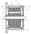
- FIG. 1 is a cross-sectional view of a rotating electrical machine 10 according to the present embodiment.
- the rotary electric machine 10 is disposed inside the liquid cooling jacket 130.
- Liquid cooling jacket 130 is formed of the case of engine ENG and the case of transmission TR.
- the rotary electric machine 10 includes a stator 20, a housing 50 that holds the stator 20, and a rotor 11.
- a liquid cooling jacket 130 is fixed to the outer peripheral side of the housing 50.
- the inner peripheral wall of the liquid cooling jacket 130 and the outer peripheral wall of the housing 50 constitute a refrigerant passage 153 for the liquid refrigerant RF such as oil.
- the shaft 13 to which the rotor 11 is fixed is rotatably supported by bearings 144 and bearings 145 provided on the liquid cooling jacket 130. Therefore, the liquid cooling jacket 130 is also referred to as a bearing bracket.
- the liquid refrigerant accumulated in the refrigerant storage space 150 flows out to the stator 20 through the refrigerant passage 154 and the refrigerant passage 155 through the refrigerant passage 153.
- the stator 20 is cooled.
- the refrigerant RF may be oil for cooling.
- the stator 20 is fixed to the inner peripheral side of the housing 50.
- the rotor 11 is rotatably supported on the inner peripheral side of the stator 20.
- the housing 50 is formed into a cylindrical shape by cutting of an iron-based material such as carbon steel, or by casting of cast steel or an aluminum alloy, or by press processing, and constitutes an outer cover of the rotary electric machine 10.
- the housing 50 is also referred to as a frame or a frame.
- the housing 50 is formed in a cylindrical shape by drawing a steel plate (such as a high tensile steel plate) having a thickness of about 2 to 5 mm.
- the housing 50 is provided with a plurality of flanges (not shown) attached to the liquid cooling jacket 130.
- the plurality of flanges are provided radially outwardly at one end surface peripheral edge of the cylindrical housing 50.
- the flange is formed by cutting away a portion other than the flange at an end portion formed at the time of drawing processing, and is integral with the housing 50.
- the stator 20 may be directly fixed to the liquid-cooled jacket 130, which is a case, without providing the housing 50.
- FIG. 2 is an overall perspective view of the stator 20.
- FIG. 3 is an overall perspective view of the stator core 132.
- the stator 20 is configured of a stator core 132 and a stator coil 60.
- the stator core 132 is made by laminating thin plates of silicon steel plates.
- the stator coils 60 are wound around slots 420 provided in large numbers on the inner circumferential portion of the stator core 132.
- the heat generated from the stator coil 60 is transferred to the liquid cooling jacket 130 through the stator core 132, and is dissipated by the refrigerant RF flowing in the liquid cooling jacket 130.
- the rotor 11 is composed of a rotor core 12 and a shaft 13.
- FIG. 4 is a cross sectional view showing a cross section of the rotor 11 and the stator core 132.
- illustration of the shaft 13 was abbreviate
- the rotor core 12 is made by laminating thin plates of silicon steel plates.
- the shaft 13 is fixed at the center of the rotor core 12.
- the shaft 13 is rotatably held by a bearing 144 and a bearing 145 attached to the liquid cooling jacket 130 as shown in FIG. 1, and at a predetermined position in the stator 20, at a position facing the stator 20. Rotate.
- the rotor 11 is provided with a permanent magnet 18 and an end ring.
- a plurality of slots 420 parallel to the axial direction of the stator core 132 are formed at equal intervals in the circumferential direction.
- the number of slots 420 is, for example, 72 in the present embodiment, and the stator coils 60 described above are accommodated in the slots 420.
- the inner peripheral side of each slot 420 is an opening, and the circumferential width of this opening is approximately equal to or slightly smaller than the coil mounting portion of each slot 420 to which stator coil 60 is mounted. There is.
- Teeth 430 are formed between the slots 420, and each tooth 430 is integral with the annular core back 440. That is, the stator core 132 is an integral core in which the teeth 430 and the core back 440 are integrally formed. The teeth 430 guide the rotating magnetic field generated by the stator coil 60 to the rotor 11 to generate rotating torque in the rotor 11.
- the stator core 132 is formed by stamping an electromagnetic steel plate having a thickness of about 0.05 to 1.0 mm and laminating a plurality of annular steel plates having an annular shape.
- the weld portion 200 is provided parallel to the axial direction of the stator core 132 at the outer peripheral portion of the cylindrical stator core 132 by TIG welding, laser welding, or the like.
- the stator core 132 may be directly inserted into the case and fixed by caulking or the like without providing the welding portion 200.
- FIG. 4 is a cross-sectional view of the rotor 11 and the fixing 20 which cut the axial direction at right angles.
- magnet insertion holes 810 into which the rectangular permanent magnets 18 are inserted are formed at equal intervals.
- a permanent magnet 18 is fixed to each magnet insertion hole 810 by an adhesive, powder resin, mold or the like.
- the circumferential width of the magnet insertion hole 810 is set larger than the circumferential width of the permanent magnet 18, and magnetic air gaps 156 are formed on both sides of the permanent magnet 18.
- the magnetic air gap 156 may be embedded with an adhesive or may be integrally fixed with the permanent magnet 18 with a molding resin.
- the permanent magnets 18 serve to form field poles of the rotor 11.
- one permanent magnet 18 is used to form one magnetic pole.
- the number of permanent magnets 18 constituting each magnetic pole may be increased. By increasing the permanent magnets 18, each permanent magnet emits The magnetic flux density of the magnetic pole is increased, and the magnet torque can be increased.
- the magnetization direction of the permanent magnet 18 is in the radial direction, and the direction of the magnetization direction is reversed for each field pole. That is, assuming that the stator side surface of the permanent magnet 18 for forming a certain magnetic pole is magnetized to the N pole and the shaft side face to the S pole, the stator side surface of the permanent magnet 18 forming the next magnetic pole is the S pole The surface on the axis side is magnetized so as to be an N pole.
- These permanent magnets 18 are magnetized and arranged so that the magnetization direction changes alternately for each magnetic pole in the circumferential direction. In the present embodiment, twelve permanent magnets 18 are arranged at equal intervals, and the rotor 11 forms twelve poles.
- the auxiliary magnetic pole 160 is formed between the permanent magnets 18 forming the magnetic pole.
- the auxiliary magnetic pole 160 acts to reduce the reluctance of the q-axis magnetic flux generated by the stator coil 60. Then, the auxiliary magnetic pole 160 makes the reluctance of the q-axis magnetic flux much smaller than the reluctance of the d-axis magnetic flux, so that a large reluctance torque is generated.
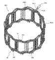
- FIG. 5 is an overall perspective view showing the stator coil 60.
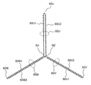
- FIG. 6 is a conceptual view showing a connection state of the stator coil 60.
- the stator coil 60 a two-star stator coil in which two star connections shown in FIG. 6 are connected in parallel is employed as the stator coil 60. That is, the stator coil 60 is provided with a star connection of the U1 phase coil 60U1, the V1 phase coil 60V1 and the W1 phase coil 60W1, and a star connection of the U2 phase coil 60U2, the V2 phase coil 60V2 and the W2 phase coil 60W2.
- N1 and N2 are neutral points of the respective star connections.
- the stator coil 60 may be round or square in cross section. However, since it tends to lead to an improvement in efficiency by making the internal cross section of the slot 420 as effective as possible and reducing the space in the slot, a square cross section is a point of efficiency improvement Desirable.
- the length of each side of the rectangular cross section may be set to be long in the radial direction of the stator core 132 or conversely, may be set to be long in the circumferential direction.
- stator coil 60 of this embodiment a rectangular wire of rectangular cross section is used, and the long side of the rectangular cross section is aligned in the circumferential direction of the stator core 132 in the slot 420 and the short side is of the stator core 132 They are aligned in the radial direction.
- the flat wire has an outer periphery covered with an insulating film.
- the stator coil 60 is made of oxygen free copper or oxygen free copper. For example, in the case of oxygenated copper, the oxygen content is about 10 ppm to about 1000 ppm.
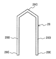
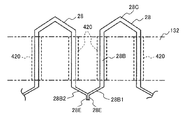
- FIG. 7A and 7B are diagrams for explaining the segment conductors 28 that constitute the stator coil 60.
- FIG. 7A shows the shape of the segment conductor 28 before being attached to the stator core 132.
- FIG. 7B shows the shape of the segment conductor 28 after being attached to the stator core 132.
- the segment conductor 28 is formed of a flat wire, and is formed in a substantially U shape having a pair of legs 28B and a top 28C connecting them.
- the pair of leg portions 28B of the segment conductor 28 are placed in different slots 420 from one side of the stator core 132 in the axial direction. insert. Thereafter, the leg 28B protruding to the other axial side of the stator core 132 is bent in the direction of the segment conductor 28 to be connected, and the end 28E of the leg 28B is made the end 28E of the other segment conductor 28 Weld.
- a set of crowns 28C projecting to one side of the stator core 132 constitutes a coil end 61 on one side of the stator coil 60 shown in FIG.
- a set of end portions 28E projecting to the other side of the stator core 132 constitute a coil end 62 on the other side of the stator coil 60 shown in FIG.
- the coil end 62 will be referred to as a welding side coil end 62
- the coil end 61 will be referred to as a non-welding side coil end 61.
- the lead-out wire 41U1 and the lead-out wire 41U2 are integrated into one by the AC terminal 42U.
- the lead wire 41V1 and the lead wire 41V2 connected to one end of the V1 phase coil 60V1 and one end of the V2 phase coil 60V2 are put together by the AC terminal 42V.
- a lead wire 41W1 and a lead wire 41W2 connected to one end of the W1 phase coil 60W1 and one end of the W2 phase coil 60W2 are combined into one by the AC terminal 42W. Further, on the side of the non-welding side coil end 61, a neutral point connection conductor 40N1 and a neutral point connection conductor 40N2 are disposed.
- the neutral point connection conductor 40N1 relates to the neutral point N1 (see FIG. 6) of one star connection, and the neutral point connection conductor 40N2 relates to the neutral point N2 of the other star connection.
- the stator coil 60 is wound in a distributed winding manner.
- the distributed winding is a winding method in which the phase winding is wound on the stator core 132 such that the phase winding is accommodated in two slots 420 spaced apart across a plurality of slots 420 (see FIG. 3). is there.
- the distributed winding is adopted as the winding method, the formed magnetic flux distribution is closer to a sine wave as compared with the concentrated winding, and has a feature of easily generating reluctance torque.
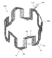
- FIG. 8 is a perspective view showing a U-phase coil 60U which is one phase of the stator coil 60 shown in FIG. As shown in FIG. 6, the U-phase coil 60U is configured by one U1 phase coil 60U1 of star connection and the U2 phase coil 60U2 of the other star connection.
- FIG. 9 is a perspective view showing the U1-phase coil 60U1.
- FIG. 10 is a perspective view showing the U2-phase coil 60U2. As shown in FIGS. 9 and 10, the neutral point connection conductor 40N1 is connected to the other end of the U1 phase coil 60U1, and the neutral point connection conductor 40N2 is connected to the other end of the U2 phase coil 60U2.
- FIG. 11 is a view showing the end 28E1 to the end 28E4 after bending of the segment conductor 28 in the welding side coil end 62. As shown in FIG.
- each leg 28B1-28B4 pulled out of each slot 420 is bent in the direction of the segment conductor 28 to be connected.
- the slot liner 310 is disposed in the legs 28B1 to 28B4 inserted into the slot 420.
- the cutting process is performed on the end portions 28E1 to 28E4 in order to make the heights of the ends of the end portions 28E1 to 28E4 uniform and to reduce the coil end height. If the heights of the coil ends are uniform, the cutting process can be eliminated.
- the end 28E1 and the end 28E2 are connected and the end 28E3 and the end 28E4 are connected by welding the end tip as shown in FIG.
- Welds in which the base material is melted and solidified are formed so as to bridge the end 28E1 and the end 28E2.
- a welded portion in which the base material is melted and solidified is formed so as to bridge the end 28E3 and the end 28E4.
- the base material of the segment conductor 28 is melted and connected by TIG welding of arc welding, plasma welding, or the like.
- As a shielding gas argon, helium, or a mixed gas of argon and helium is used.
- an insulator 300 is disposed between the four rows of segment conductors 28 arranged to be aligned in the radial direction.
- the switching speed of the power conversion device INV shown in FIG. 19 increases, the surge level increases, causing insulation deterioration of the coil of the rotating electrical machine 10 and affecting the life of the rotating electrical machine 10 ing. Therefore, although the enamel coating is thickened, if the enamel coating is thickened, the forming accuracy of the coil becomes worse. Furthermore, the thicker the enamel coating, the higher the cost of the parts.
- the lead wire 41U1 and lead wire 41U2 (see FIG. 8) to which a steep surge voltage is input from the power conversion device INV, the lead wires 41V1 and 41V2, the overlap of the insulator 300 on the welding side coil end 62 side of the lead wires 41W1 and 41W2.
- the withstand voltage between the segment conductors 28 is improved.
- the insulator 300 may be provided also on the non-welding side coil end 61 side, and the overlapping portion 302 is provided around the lead wire 41U1 and lead wire 41U2, the lead wire 41V1 and lead wire 41V2, the lead wire 41W1 and the lead wire 41W2.
- FIG. 12 is a perspective view of the weld side coil end 62 before the insulator 300 having the overlapping portion 302 is inserted between the segment conductors 28.
- FIG. 13 is a perspective view just before inserting the insulator 300 according to the present embodiment between the segment conductors 28. As shown in FIG.
- the insulator 300 is annularly disposed between the segment conductors 28 in order to improve interphase insulation and interconductor insulation in the weld side coil end 62.
- the insulator 300 also functions as a holding member for preventing dripping when a resin member (for example, polyester or epoxy liquid varnish) is dropped on the whole or a part of the stator coil 60.
- the insulator 300 is, for example, an insulating sheet of heat-resistant polyamide paper, and has a thickness of about 0.1 to 0.5 mm.
- the overlapping portion 302 is thicker and about 0.2 to 1.0 mm.
- the overlapping portion 302 comes to the position of the segment conductor 28 connected to the lead wire 41U1 and lead wire 41U2 and lead wire 41V1 and lead wire 41V2 and lead wire 41W1 and lead wire 41W2.
- the insulator 300 is disposed so as to overlap in the same direction as the bending direction of the coil (the circumferential length of the insulator 300 is made longer than the circumferential length of the stator coil 60). It is possible to prevent the displacement of the height of the insulating sheet such as 300 and the winding of the insulating sheet.
- the overlapping portion 302 of the insulator 300 is disposed at the position of the segment conductor 28 connected to the lead wire 41U1 or the like, but the overlapping portion 302 is provided at a position where the segment conductor 28 is likely to be deformed by external force. You may do so.
- FIG. 14 shows the insulator 300 as viewed from the rotational axis direction of the rotary electric machine 10.
- the insulator 300 forms an overlapping portion 302 by forming a substantially rectangular insulating paper member into a substantially ring shape.
- FIG. 15 shows an insulator 300 according to another embodiment as viewed from the rotational axis direction of the rotary electric machine 10.
- the insulator 300 according to the present embodiment can further improve the insulation by forming a push-back portion and forming the overlap portion 302.
- By arranging the overlapping of the insulators 300 in the same direction as the bending direction of the coil it is possible to prevent the displacement of the height of the insulating sheet such as the insulator 300 and the winding of the insulating sheet at the time of coil bending. .
- FIG. 16 shows an insulator 300 according to another embodiment as viewed from the rotational axis direction of the rotary electric machine 10.
- the insulator 305 according to this embodiment is thicker than the other portions in the arrangement range of the lead wire 41U1 and the lead wire 41U2, the lead wire 41V1 and the lead wire 41V2, and the segment conductor 28 connected to the lead wire 41W1 and the lead wire 41W202.
- the formed thick resin portion 304 is disposed.
- the insulator 305 is molded of resin. Ease of insertion when inserting the welding side coil end 62 is also improved. Since it is a resin molded product, it is possible to prevent displacement and winding during coil bending.
- FIG. 17A is a side view of the insulator 300 before bending the overlapping portion 302 according to another embodiment.
- FIG. 17B is a side view of the insulator 300 after bending the overlapping portion 302 according to another embodiment.
- FIG. 17C shows an insulator 300 according to another embodiment as viewed from the rotational axis direction of the rotary electric machine 10.
- the overlapping portion 302 is disposed in the arrangement range of the lead wire 41U1 and the lead wire 41U2, the lead wire 41V1 and the lead wire 41V2, and the segment conductor 28 connected to the lead wire 41W1 and the lead wire 41W202.
Landscapes
- Engineering & Computer Science (AREA)
- Power Engineering (AREA)
- Insulation, Fastening Of Motor, Generator Windings (AREA)
- Windings For Motors And Generators (AREA)
Abstract
Description
まず、図18を参照して、回転電機が搭載される車両の概略構成を説明する。前輪側の主動力として、エンジンENGと回転電機10を有する。エンジンENGと回転電機10の発生する動力は、変速機TRにより変速され、前輪側駆動輪FWに動力を伝えられる。また、後輪の駆動においては、後輪側に配置された回転電機10と後輪側駆動輪RWを機械的に接続され、動力が伝達される。前輪側の動力源である回転電機10は、エンジンENGと変速機TRの間に配置される。
図1は、本実施形態に係る回転電機10の断面図である。本実施形態においては、回転電機10は、液冷ジャケット130の内部に配設されている。液冷ジャケット130は、エンジンENGのケースや変速機TRのケースによって構成される。回転電機10は、固定子20と、固定子20を保持するハウジング50と、回転子11と、を備えている。
また反溶接側コイルエンド61の側には、中性点結線用導体40N1及び中性点結線用導体40N2が配置されている。中性点結線用導体40N1は一方のスター結線の中性点N1(図6参照)に関するものであり、中性点結線用導体40N2は他方のスター結線の中性点N2に関するものである。
-曲げ加工-
次に、本実施形態における固定子20の製造方法について説明する。前述したように、図7Aの状態のセグメント導体28を固定子鉄心132のスロット内に挿入した後、図7Bのように脚部28Bを接続すべき他のセグメント導体28の方向に曲げ加工する。各スロット420から引き出された各脚部28Bは、接続すべきセグメント導体28の方向に曲げられる。例えば、スロット420から突出する脚部28B1は周方向左側に曲げられる。一方、端部28E2を有する脚部28B2は、周方向右側に曲げられる。そして、端部28E1と端部28E2は径方向に隣接するように配置される。
Claims (5)
- 周方向に並んだ複数のスロットが形成された固定子鉄心と、
前記スロット内に挿入されかつ略U字形状に成形された複数のセグメントコイルと、
複数の前記セグメントコイルとの間に配置されたインシュレーターと、を備え、
前記インシュレーターは、前記インシュレーターの一部が前記インシュレーターの他の部分よりも厚く形成される部分を有する回転電機の固定子。 - 請求項1に記載された回転電機の固定子であって、
前記インシュレーターは、複数の前記セグメントコイルが並べられた周方向の長さよりも長く形成されており、
前記インシュレーターが厚く形成される部分は、前記インシュレーターの両端部を含む部分を周方向に重ねることにより形成される回転電機の固定子。 - 請求項1に記載された回転電機の固定子であって、
複数の前記セグメントコイルのうち前記インシュレーターの厚く形成された部分と重なるセグメント導体は、口出し線と繋がる回転電機の固定子。 - 請求項3に記載された回転電機の固定子であって、
前記口出し線は、U相とV相とW相のそれぞれに対応する複数の前記口出し線により構成される回転電機の固定子。 - 請求項1に記載された固定子を用いる回転電機であって、
前記固定子と対向する回転子を備える回転電機。
Priority Applications (3)
| Application Number | Priority Date | Filing Date | Title |
|---|---|---|---|
| DE112018002327.3T DE112018002327B4 (de) | 2017-06-28 | 2018-04-09 | Dynamoelektrische Maschine |
| CN201880037748.5A CN110771013B (zh) | 2017-06-28 | 2018-04-09 | 旋转电机的定子以及旋转电机 |
| JP2019526166A JP6793257B2 (ja) | 2017-06-28 | 2018-04-09 | 回転電機の固定子、及び回転電機 |
Applications Claiming Priority (2)
| Application Number | Priority Date | Filing Date | Title |
|---|---|---|---|
| US15/635,269 | 2017-06-28 | ||
| US15/635,269 US10715001B2 (en) | 2017-06-28 | 2017-06-28 | Dynamo-Electric Machine |
Publications (1)
| Publication Number | Publication Date |
|---|---|
| WO2019003561A1 true WO2019003561A1 (ja) | 2019-01-03 |
Family
ID=64739186
Family Applications (1)
| Application Number | Title | Priority Date | Filing Date |
|---|---|---|---|
| PCT/JP2018/014877 Ceased WO2019003561A1 (ja) | 2017-06-28 | 2018-04-09 | 回転電機の固定子、及び回転電機 |
Country Status (5)
| Country | Link |
|---|---|
| US (1) | US10715001B2 (ja) |
| JP (1) | JP6793257B2 (ja) |
| CN (1) | CN110771013B (ja) |
| DE (1) | DE112018002327B4 (ja) |
| WO (1) | WO2019003561A1 (ja) |
Cited By (1)
| Publication number | Priority date | Publication date | Assignee | Title |
|---|---|---|---|---|
| JP2022013230A (ja) * | 2020-07-03 | 2022-01-18 | Dmg森精機株式会社 | モータ |
Families Citing this family (7)
| Publication number | Priority date | Publication date | Assignee | Title |
|---|---|---|---|---|
| US10944804B1 (en) | 2017-11-22 | 2021-03-09 | Amazon Technologies, Inc. | Fragmentation of time-associated data streams |
| CN113039709A (zh) * | 2018-11-16 | 2021-06-25 | 株式会社东芝 | 定子的制造方法 |
| US12609572B2 (en) * | 2020-12-23 | 2026-04-21 | Lg Electronics Inc. | Stator of rotating electric machine |
| TWI770765B (zh) * | 2021-01-13 | 2022-07-11 | 天容寶節能科技股份有限公司 | 利於使用於海洋能發電之永磁發電機 |
| TWI780570B (zh) | 2021-01-13 | 2022-10-11 | 富連海能源科技有限公司 | 多軸波浪發電裝置 |
| TWI780568B (zh) * | 2021-01-13 | 2022-10-11 | 富連海能源科技有限公司 | 波浪發電裝置以及雙軸波浪發電裝置 |
| CN119698745A (zh) * | 2022-03-15 | 2025-03-25 | 依拉菲动力技术有限公司 | 一种电机绕组、电机及其制造方法 |
Citations (4)
| Publication number | Priority date | Publication date | Assignee | Title |
|---|---|---|---|---|
| JPS54169202U (ja) * | 1978-05-20 | 1979-11-29 | ||
| JPH02133046A (ja) * | 1988-11-09 | 1990-05-22 | Sanyo Electric Co Ltd | 電動機の絶縁装置 |
| JP2012080699A (ja) * | 2010-10-04 | 2012-04-19 | Toyota Motor Corp | 回転電機ステータ |
| JP2014096855A (ja) * | 2012-11-07 | 2014-05-22 | Toyota Industries Corp | 回転電機における相間絶縁シート、及び電動圧縮機 |
Family Cites Families (18)
| Publication number | Priority date | Publication date | Assignee | Title |
|---|---|---|---|---|
| JP2941164B2 (ja) * | 1994-04-28 | 1999-08-25 | 本田技研工業株式会社 | 多相ステータ |
| JP2004023916A (ja) * | 2002-06-18 | 2004-01-22 | Denso Corp | 回転電機の固定子 |
| JP4797371B2 (ja) * | 2004-12-07 | 2011-10-19 | 日産自動車株式会社 | 電力変換装置の制御方法 |
| JP4887128B2 (ja) * | 2006-12-07 | 2012-02-29 | 日立オートモティブシステムズ株式会社 | 回転電機 |
| JP2009124902A (ja) * | 2007-11-16 | 2009-06-04 | Hitachi Ltd | 回転電機およびそれを備えた車載用電機システム |
| US8125115B2 (en) * | 2008-07-21 | 2012-02-28 | Emerson Electric Co. | End turn phase insulator with a lead wire restraining tab and method of restraining lead wires on dynamoelectric devices |
| CN201378490Y (zh) * | 2009-04-06 | 2010-01-06 | 浙江正亮电子电气有限公司 | 双漆包线圈电抗器 |
| JP5510709B2 (ja) | 2010-01-22 | 2014-06-04 | 株式会社デンソー | 回転電機の固定子 |
| JP5734591B2 (ja) * | 2010-07-20 | 2015-06-17 | 東芝産業機器システム株式会社 | 回転電機のステータ及び回転電機 |
| JP5583508B2 (ja) * | 2010-07-29 | 2014-09-03 | 日立オートモティブシステムズ株式会社 | 回転電機 |
| JP2012231638A (ja) * | 2011-04-27 | 2012-11-22 | Toyota Motor Corp | 回転電機ステータ |
| KR101784524B1 (ko) * | 2011-08-22 | 2017-10-11 | 현대모비스 주식회사 | 트랙션 모터 |
| JP5816567B2 (ja) * | 2012-02-01 | 2015-11-18 | 日立オートモティブシステムズ株式会社 | 回転電機 |
| WO2014034157A1 (ja) * | 2012-08-31 | 2014-03-06 | 三菱電機株式会社 | 回転電機およびその製造方法 |
| JP6090572B2 (ja) * | 2013-04-27 | 2017-03-08 | 日本電産株式会社 | モータおよびモータの製造方法 |
| JP6356394B2 (ja) * | 2013-08-07 | 2018-07-11 | 株式会社東芝 | 回転電機、及び回転電機の製造方法 |
| DE102014208082B4 (de) * | 2014-04-29 | 2019-03-07 | Continental Automotive Gmbh | Verfahren und Vorrichtung zum Herstellen einer Wicklung einer elektrischen Maschine |
| US10305335B2 (en) * | 2016-07-14 | 2019-05-28 | Hitachi Automotive Systems, Ltd. | Stator for rotating electrical machine and rotating electrical machine |
-
2017
- 2017-06-28 US US15/635,269 patent/US10715001B2/en active Active
-
2018
- 2018-04-09 WO PCT/JP2018/014877 patent/WO2019003561A1/ja not_active Ceased
- 2018-04-09 JP JP2019526166A patent/JP6793257B2/ja active Active
- 2018-04-09 CN CN201880037748.5A patent/CN110771013B/zh active Active
- 2018-04-09 DE DE112018002327.3T patent/DE112018002327B4/de active Active
Patent Citations (4)
| Publication number | Priority date | Publication date | Assignee | Title |
|---|---|---|---|---|
| JPS54169202U (ja) * | 1978-05-20 | 1979-11-29 | ||
| JPH02133046A (ja) * | 1988-11-09 | 1990-05-22 | Sanyo Electric Co Ltd | 電動機の絶縁装置 |
| JP2012080699A (ja) * | 2010-10-04 | 2012-04-19 | Toyota Motor Corp | 回転電機ステータ |
| JP2014096855A (ja) * | 2012-11-07 | 2014-05-22 | Toyota Industries Corp | 回転電機における相間絶縁シート、及び電動圧縮機 |
Cited By (1)
| Publication number | Priority date | Publication date | Assignee | Title |
|---|---|---|---|---|
| JP2022013230A (ja) * | 2020-07-03 | 2022-01-18 | Dmg森精機株式会社 | モータ |
Also Published As
| Publication number | Publication date |
|---|---|
| US20190006900A1 (en) | 2019-01-03 |
| DE112018002327B4 (de) | 2025-12-04 |
| US10715001B2 (en) | 2020-07-14 |
| JP6793257B2 (ja) | 2020-12-02 |
| DE112018002327T5 (de) | 2020-01-16 |
| CN110771013A (zh) | 2020-02-07 |
| JPWO2019003561A1 (ja) | 2020-02-27 |
| DE112018002327T8 (de) | 2020-04-09 |
| CN110771013B (zh) | 2022-05-06 |
Similar Documents
| Publication | Publication Date | Title |
|---|---|---|
| JP6402257B2 (ja) | 固定子コイル、これを備えた固定子、およびこれを備えた回転電機 | |
| JP6563595B2 (ja) | 回転電機、及び回転電機の固定子 | |
| JP6793257B2 (ja) | 回転電機の固定子、及び回転電機 | |
| JP6777760B2 (ja) | 回転電機用の固定子、及び回転電機 | |
| JP7100130B2 (ja) | 回転電機の固定子、回転電機、並びに回転電機の固定子の製造方法 | |
| JP2014050207A (ja) | 回転電機及びその製造方法 | |
| JP6499064B2 (ja) | 回転電機用固定子の製造方法 | |
| CN106575890A (zh) | 旋转电机的定子和具备它的旋转电机 | |
| JP6719671B2 (ja) | 回転電機の固定子、及び回転電機 | |
| US20180248453A1 (en) | Rotor, Rotating Electric Machine Including Said Rotor, and Method of Manufacturing Said Rotor | |
| US10505426B2 (en) | Dynamo-electric machine | |
| JP7030961B2 (ja) | 固定子、及び回転電機 | |
| JP7102523B2 (ja) | 回転電機の固定子、回転電機、並びに回転電機の固定子の製造方法 | |
| US20260012055A1 (en) | Electric motor |
Legal Events
| Date | Code | Title | Description |
|---|---|---|---|
| 121 | Ep: the epo has been informed by wipo that ep was designated in this application |
Ref document number: 18824978 Country of ref document: EP Kind code of ref document: A1 |
|
| ENP | Entry into the national phase |
Ref document number: 2019526166 Country of ref document: JP Kind code of ref document: A |
|
| WWE | Wipo information: entry into national phase |
Ref document number: 112018002327 Country of ref document: DE |
|
| 122 | Ep: pct application non-entry in european phase |
Ref document number: 18824978 Country of ref document: EP Kind code of ref document: A1 |
|
| WWG | Wipo information: grant in national office |
Ref document number: 112018002327 Country of ref document: DE |