WO2019003473A1 - Amphibious vehicle - Google Patents
Amphibious vehicle Download PDFInfo
- Publication number
- WO2019003473A1 WO2019003473A1 PCT/JP2017/046061 JP2017046061W WO2019003473A1 WO 2019003473 A1 WO2019003473 A1 WO 2019003473A1 JP 2017046061 W JP2017046061 W JP 2017046061W WO 2019003473 A1 WO2019003473 A1 WO 2019003473A1
- Authority
- WO
- WIPO (PCT)
- Prior art keywords
- flap
- state
- vehicle
- drive
- navigation
- Prior art date
Links
Images


Classifications
-
- B—PERFORMING OPERATIONS; TRANSPORTING
- B60—VEHICLES IN GENERAL
- B60F—VEHICLES FOR USE BOTH ON RAIL AND ON ROAD; AMPHIBIOUS OR LIKE VEHICLES; CONVERTIBLE VEHICLES
- B60F3/00—Amphibious vehicles, i.e. vehicles capable of travelling both on land and on water; Land vehicles capable of travelling under water
- B60F3/003—Parts or details of the vehicle structure; vehicle arrangements not otherwise provided for
- B60F3/0046—Water deflectors or screens
-
- B—PERFORMING OPERATIONS; TRANSPORTING
- B60—VEHICLES IN GENERAL
- B60F—VEHICLES FOR USE BOTH ON RAIL AND ON ROAD; AMPHIBIOUS OR LIKE VEHICLES; CONVERTIBLE VEHICLES
- B60F3/00—Amphibious vehicles, i.e. vehicles capable of travelling both on land and on water; Land vehicles capable of travelling under water
- B60F3/003—Parts or details of the vehicle structure; vehicle arrangements not otherwise provided for
- B60F3/0038—Flotation, updrift or stability devices
Definitions
- the present invention relates to an amphibian.
- An amphibious vehicle capable of traveling on water and on land may be used as a water rescue vehicle or a disaster countermeasure vehicle, and such an amphibious vehicle is required to arrive early at a destination. Therefore, for example, by providing the amphibian with a flap, it is possible to increase the moving speed at the time of waterborne navigation and shorten the traveling time to the destination (moving time of the waterborne navigation).
- the flap is a plate-like member for making it easier to receive lift from water when traveling on an amphibious vehicle, and the flap is provided obliquely upward in the forward direction of the traveling direction of the amphibious vehicle, It has a surface (flap surface) where the angle of contact with the water surface (contact angle) is set small.
- An amphibious vehicle equipped with flaps can shift from a deep draft of draft to a shallow gliding draft of a draft while sailing on the water, thus increasing the moving speed when sailing on the water can do.
- the flaps include retractable flaps that can be deployed and retracted on the forward side of the vehicle body in the traveling direction.
- An amphibious vehicle adopting a storage type flap can be navigated in a sliding state during waterborne navigation by expanding the flap away from the vehicle body by the drive mechanism, and the flap can be moved by the drive mechanism to the vehicle body When traveling on land, the vehicle can travel while avoiding contact between the flap and a step or the like (for example, see Patent Document 1).
- the lift from the water during the water surface navigation can be achieved by lengthening the storage type flap. Furthermore, it is possible to shift from the floating state to the sliding state efficiently.
- the space for storing the storage type flap is limited, and the storage type flap may not be properly stored. . That is, when the elongated storage flap interferes with the driver's seat or the like at the time of storage, the flap of the amphibious vehicle can not be elongated.
- the present invention has been made in view of the above problems, and it is an object of the present invention to make a flap longer and to be able to be stored properly.
- An amphibious vehicle for solving the above problems is an amphibious vehicle provided with a flap for receiving lift from water when traveling on water, which can be deployed and stored on the forward side in the traveling direction of the vehicle body.
- the flap has a lower flap stored so as to be close to the front of the vehicle main body and an upper flap stored so as to be close to the upper surface of the vehicle main body, and the lower flap and the upper flap
- At least one of the first and second flap members is characterized in that the flap length in the direction orthogonal to the vehicle width direction is variable.
- An amphibian according to a second aspect of the present invention for solving the above problems is the amphibian according to the first aspect, wherein the first flap member and the second flap member are slidably connected to each other.
- the flap is characterized in that the flap length is made variable by the sliding movement of the first flap member and the second flap member.
- An amphibian according to a third aspect of the present invention for solving the above problems is the amphibian according to the first aspect, wherein the first flap member and the second flap member are rotatably connected to each other.
- the flap is characterized in that the flap length is made variable by the rotational movement of the first flap member and the second flap member.
- An amphibious vehicle for solving the above-mentioned problems is the amphibian according to any one of the first to third inventions, wherein the drive for expanding and storing the flap, and movement on the water
- a navigation state detection device capable of detecting the navigation state of the vehicle, and a control device for controlling driving of the drive device based on a detection result of the navigation state detection device.
- An amphibious vehicle according to a fifth aspect of the present invention for solving the above-mentioned problems is the amphibious vehicle according to the fourth aspect, wherein in the control device, the navigation state detection device detects that the navigation state is a floating state The driving device is operated to increase the flap length, and the driving device is operated to reduce the flap length when the navigation state detection device detects that the navigation state is the sliding state.
- the apparatus is characterized in that it operates.
- the flap can be lengthened and appropriately stored.
- lift force can be increased during navigation on the water of the amphibious vehicle, so that the sliding area can be efficiently reached.
- the contact angle between the elongated flap and the water surface (water line) By setting it small, resistance can be reduced when traveling on the water of the amphibious vehicle, and the sliding area can be reached more efficiently.
- the flaps which can be stored in an appropriate size with a simple structure.
- the flap which can be stored in an appropriate size as well as to be simple.
- the flap can be appropriately deployed and stored according to the navigation state (floating state, sliding state, etc.) of the amphibian.
- the navigation condition of the amphibious vehicle when the navigation condition of the amphibious vehicle is in a floating state or a sliding state, it is possible to appropriately deploy and store the flaps and efficiently navigate the water. it can.
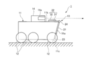
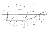
- FIG. 1 is an explanatory view showing a structure of an amphibian according to a first embodiment (during land traveling). BRIEF DESCRIPTION OF THE DRAWINGS It is explanatory drawing which shows the structure (floating state in the time of surface navigation) of the amphibious vehicle which concerns on Example 1.
- FIG. FIG. 2 is an explanatory view showing a structure of an amphibian according to the first embodiment (a sliding state at the time of water navigation).
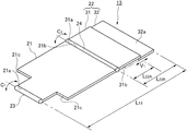
- FIG. 2 is an explanatory view showing a structure of a flap provided in the amphibian according to the first embodiment.
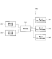
- FIG. 2 is a block diagram of a control device that controls the operation of a flap provided in the amphibian according to the first embodiment.
- FIG. 10 is an explanatory view showing a structure of an amphibian according to a second embodiment (during land traveling). It is explanatory drawing which shows the structure (the floating state at the time of waterborne navigation) of the amphibious vehicle which concerns on Example 2.
- FIG. FIG. 7 is an explanatory view showing a structure of an amphibian according to a second embodiment (a sliding state at the time of water navigation).
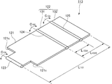
- FIG. 8 is an explanatory view showing a structure of a flap provided in the amphibian according to the second embodiment.
- FIG. 10 is a block diagram of a control device that controls the operation of a flap provided in the amphibian according to the second embodiment.
- Example 1 The structure of the amphibian according to the first embodiment of the present invention will be described with reference to FIGS. 1 to 5.
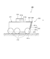
- the amphibious vehicle 1 is equipped with a wheeled (or tracked) 12 at the lower part of the vehicle body 11, and travels on the land by driving the wheeled wheel 12 by a drive source (not shown). It can be done.
- the amphibious vehicle 1 is provided with a propeller (not shown), and can be navigated on the water by driving the propeller with a driving source (not shown) (see FIG. 2). That is, the amphibian 1 is capable of traveling on water and on land.
- a flap (plate-like member) 13 for making it easy to receive lift from water when traveling on water is the forward side in the traveling direction of the vehicle main body 11 (in FIG. Provided on the other side). Therefore, the amphibious vehicle 1 travels on the water by transferring its sailing state from the deep floating state of the draft to the shallow sliding state of the draft by receiving lift from the water by the flap 13 at the time of marine navigation it can.
- the flap 13 is one that can be deployed and stored in the vehicle body 11 (retractable flap), and is stored so as to approach (contact) the front surface 11 a of the vehicle body 11 And an upper flap 22 housed so as to approach (contact) the upper surface 11 b of the vehicle main body 11.
- the lower flap 21 is a substantially T-shaped plate-like member, and the lower end edge 21a with its narrow width is on the front side in the traveling direction of the vehicle body 11 via the hinge 23. Is connected to the lower end edge 11c.
- the lower flap 21 is mechanically connected to a first flap drive device 41 (see FIG. 5) for rotating the lower flap 21 with respect to the vehicle main body 11. It is adapted to be rotated to the rotation axis C 1 around which extends in the vehicle width direction.
- the upper flap 22 is roughly configured of a first upper flap 31 and a second upper flap 32 that can slide relative to each other, and the first upper flap 31 and the second upper flap 32
- the flap length (the length in the direction in which the flap (the upper flap 22 extends perpendicularly to the vehicle width direction) is variably configured by the sliding operation of the above.
- the first upper flap 31 is a substantially rectangular plate-like member, and the lower end edge 31 a thereof is connected to the wide upper end edge 21 b of the lower flap 21 through the hinge 24.
- the first upper flap 31 is mechanically connected to a second flap drive device 42 (see FIG. 5) for rotating the first upper flap 31 with respect to the lower flap 21, and the lower flap is It is adapted to be rotated to the rotation axis C 2 around which extends in the vehicle width direction with respect to 21.
- the second upper flap 32 is a substantially rectangular plate-like member, and the rear surface 32 a is in contact with the front surface 31 b of the first upper flap 31 and slidably connected to the first upper flap 31.
- the second upper flap 32 is mechanically connected to a third flap drive device 43 (see FIG. 5) for sliding the second upper flap 32 relative to the first upper flap 31.
- the first upper flap 31 is slid in the V1 axis direction (the direction in which the upper flap 22 (the first upper flap 31 and the second upper flap 32) extends orthogonal to the vehicle width direction) There is.
- the upper flap 22 is substantially equivalent to the conventional one in a short state in which the second upper flap 32 is stored so as to overlap the first upper flap 31 (in the state shown by the two-dot chain line in FIG. 5).
- the amphibian 1 is provided with a control device 44 for controlling the operation (deployment and storage) of the flap 13.
- the control device 44 is electrically connected to the first flap drive device 41, the second flap drive device 42 and the third flap drive device 43, respectively, and the first flap drive device 41, the second The drive of the flap drive 42 and the third flap drive 43 can be controlled independently.
- first flap drive device 41 the second flap drive device 42 and the third flap drive device 43
- various drive sources and mechanisms can be adopted, respectively.
- a hydraulic cylinder a telescopic member
- a drive source may be inserted between the members (between the vehicle main body 11 and the lower flap 21, between the lower flap 21 and the first upper flap 31, the first upper flap 31 and the second upper flap)
- By providing them between 32 and 32 it is possible to perform rotational operation and sliding operation between the members by utilizing the extension and contraction operation of the hydraulic cylinder.
- the motor power generator
- the gear mechanism or wire mechanism
- the amphibious vehicle 1 includes a movement condition detection device 45 capable of detecting the movement condition (water navigation or land traveling, etc.) of the amphibian 1, and the amphibious vehicle at the time of water navigation.
- a navigation state detection device 46 capable of detecting one navigation state is provided.
- the movement state detection means 45 and the navigation state detection device 46 are electrically connected to the control device 44 respectively, and the control device 44 performs the first operation based on the detection results of the movement state detection 45 and the navigation state detection device 46.
- the drive of the flap drive 41, the second flap drive 42 and the third flap drive 43 are controlled.
- various sensors or the like can be adopted as the movement state detection device 45 and the navigation state detection device 46.
- the movement state detection device 45 a switch operated by a passenger, a water pressure sensor for detecting that the amphibious vehicle 1 has been launched can be adopted, and as the navigation state detection device 46, movement in water navigation A speed sensor or the like that detects the speed can be employed.
- the control device 44 lifts the amphibian 1 when the movement speed of the amphibian 1 during the water navigation is less than a predetermined value. It is determined that the vehicle is in the state, and if the traveling speed of the amphibian 1 while traveling on the water is equal to or more than a predetermined value, it is determined that the amphibian 1 is in the sliding state.
- the flap 13 is in the fully stored state (see FIG. 1).
- the flap 13 in the fully stored state is stored such that the lower flap 21 approaches the front surface 11a of the vehicle main body 11, and the upper flap 22 is stored so as to approach the upper surface 11b of the vehicle main body 11 in the short state. It is.
- the movement state detection device 45 detects that the amphibian 1 moves from the land state It detects that it has transitioned to the surface navigation state (see FIGS. 2 and 5).
- the amphibian 1 is in the deep floating state of the draft, so that the navigation state detection device 46 operates the navigation of the amphibian 1 It detects that the state is a floating state.
- control unit 44 controls the first flap drive unit 41, the second flap drive unit 42 and the third flap drive unit 43 based on the detection results of the movement state detection unit 45 and the navigation state detection unit 46. Are respectively driven to transform the flaps 13 from the fully stored state to the fully expanded state.
- the lower flap 21 is deployed away from the front surface 11 a of the vehicle body 11 and the upper flap 22 is deployed away from the upper surface 11 b of the vehicle body 11 in the elongated state. is there.
- the lower flap 21 is expanded by the first flap drive device 41 so as to be away from the front surface 11a of the vehicle body 11;
- the first upper flap 31 is developed away from the top surface 11b of the vehicle body 11 by the second flap drive 42, and the second upper flap 32 is displaced relative to the first upper flap 31 by the third flap drive 43.
- the navigation state detection device 46 changes the navigation state of the amphibious vehicle 1 from the floating state to the sliding state To detect (see FIGS. 3 and 5).
- control unit 44 drives only the third flap drive unit 43 based on the detection result of the navigation state detection unit 46, and transforms the flap 13 from the fully expanded state to the partially expanded state (partially stored state). .
- the flap 13 in the partially expanded state (partially stored state) is expanded so that the lower flap 21 is separated from the front surface 11 a of the vehicle body 11 and expanded so that the upper flap 22 is separated from the upper surface 11 b of the vehicle body 11 in a short length state. It is in a state of being
- the second upper flap 32 is driven with the third flap while the lower flap 21 and the first upper flap 31 are unfolded.
- the device 43 is stored so as to overlap the first upper flap 31.
- the navigation state detection device 46 changes the navigation state of the amphibious vehicle 1 from the sliding state to the floating state To detect (see FIGS. 2 and 5).
- control unit 44 drives only the third flap drive unit 43 based on the detection result of the navigation state detection unit 46, and transforms the flap 13 from the partially expanded state (partially stored state) to the fully expanded state. .
- the second upper flap 32 is driven with the third flap while the lower flap 21 and the first upper flap 31 are unfolded.
- the device 43 is deployed to be offset relative to the first upper flap 31.
- the movement state detection device 45 causes the amphibian 1 to move from the sea state to the land It detects that the vehicle has shifted to the traveling state (see FIGS. 1 and 5).
- control device 44 drives the first flap drive device 41, the second flap drive device 42 and the third flap drive device 43 based on the detection result of the movement state detection device 45, and the flap is Transform 13 from the fully developed state to the fully stored state.
- the second upper flap 32 is stored by the third flap drive device 43 so as to overlap the first upper flap 31.
- the lower flap 21 is stored by the first flap drive device 41 so as to be close to the front surface 11a of the vehicle body 11, and the first upper flap 31 (upper flap 22) is moved by the second flap drive device 42. It is stored so as to be close to the upper surface 11 b of 11.
- the flap length L 22B of the upper flap 22 in the long state can be
- the flap length L 13 of the flap 13 in the fully deployed state can be set longer than that of the conventional one (see FIG. 4).
- the contact angle theta 1 between the flaps 13 and the water surface (waterline) 100 be set to be smaller than that of the conventional Yes (see Figure 2).
- the amphibian 1 travels while reducing the water resistance more than conventional ones while traveling on the water. Therefore, it is possible to shift from the floating state to the sliding state more efficiently and to move to the destination faster than the conventional one.
- the flap length L 22A of the upper flap 22 in the short state is substantially the same as that of the conventional one. It can be set to the same length (see FIGS. 1 and 4).
- the upper flap 22 in the short state is set to a flap length L 22A substantially equivalent to that of the conventional one, without interfering with the driver's seat 14 or the like provided protruding from the upper surface 11 b of the vehicle main body 11
- the upper flaps 22 (the first upper flap 31 and the second upper flap 32) can be stored close to the top surface 11b of the vehicle body 11 without obstructing the view of the driver's seat 14 from the car window 14a.
- the upper flap 22 (the first upper flap 31 and the second upper flap 32) in the short state can be stored close to the upper surface 11b of the vehicle main body 11 Since it is possible, the lower flap 21 can be stored so as to be close to the front surface 11a of the vehicle main body 11 (see FIG. 1).
- the amphibian 1 can be used on land without traveling the flap 13 (lower flap 21) with a step or the like when traveling on land. It is possible to travel (rough terrain, steps, etc.).
- the upper flap 22 is configured to have a variable flap length
- the upper flap 22 by a short condition, it is possible to suppress the amount of protrusion D 1 projecting from the water surface of the flap 13 (waterline) 100 (see FIG. 3).
- amphibian 1 By suppressing the protrusion amount D 1 of the water surface 100 of the flap 13 in this manner planing state, amphibian 1, it is possible to sail by reducing the resistance of air during water cruising, efficiency planing state You can travel quickly to your destination.
- the amphibian 1 even if the front portion of the vehicle body 11 is inclined upward (upward vertical direction) in planing state, suppressing the protrusion amount D 1 of the water surface 100 of the flap 13 As a result, it is possible to ensure good visibility in the horizontal direction from the car window 14a of the driver's seat 14 (see FIG. 3).
- the upper flaps 22 are roughly configured of a first upper flap 31 and a second upper flap 32 that can slide relative to each other, and a sliding operation between the first upper flap 31 and the second upper flap 32
- the flap length of the upper flap 22 (flap 13) is variable.
- the present invention is not limited to the configuration of this embodiment.
- the upper stage flaps 122 are roughly configured of a first upper stage flap 131 and a second upper stage flap 132 that are rotatable relative to each other, and the rotational movement of the first upper stage flap 131 and the second upper stage flap 132
- the flap length of the upper flap 122 may be variably configured by (rotating so as to fold the second upper flap 132 with respect to the first upper flap 131).
- the storage type flap 113 of such a configuration is connected to the lower flap 121 rotatably connected around the rotation axis C 101 via the hinge 123 and the vehicle body of the amphibious vehicle (not shown), and the lower flap 121 and the hinge 124 A first upper flap 131 rotatably connected about the rotation axis C 102 via the second upper flap 132, and a second upper flap 132 rotatably connected about the rotation axis C 103 via the first upper flap 131 and the hinge 125.
- the amphibious vehicle provided with the storage type flap 113 having the above-described configuration exhibits the same function and effect as the amphibious vehicle 1 according to the first embodiment.
- the lower flap 21 in order to avoid interference between the lower flap 21 (lower flap 121) and the wheel 12, the lower flap 21 is formed in a substantially T shape, and the notch 21c is formed in the lower flap 21. (The notch 121c) is provided.
- the present invention is not limited to the configuration of this embodiment.
- the lower flap may be formed in a shape close to a rectangular shape so as to avoid interference with the wheel, and the notch portion of the lower flap formed in a substantially T shape can be closed when sailing on water It is good also as composition.
- the movement state detection device 45 detects the transition state
- the control device 44 detects the movement state detection device 45.
- the drive of the first flap drive device 41, the second flap drive device 42 and the third flap drive device 43 is controlled based on the detection result of the above.
- the present invention is not limited to the operation of this embodiment.
- control device may control the drive of the first flap drive device, the second flap drive device and the third flap drive device based on the operation of the switch which is the movement state detection device, and
- the movement state detection device can predict the transition of the movement state of the amphibious vehicle, and the control device is the first flap drive device before the movement state transition of the amphibious vehicle (immediately), the second flap
- the drive of the drive unit and the third flap drive unit may be controlled. According to these operations, for example, it is also possible to store the flap while the amphibian floats on the water.
- Example 2 The structure of an amphibian according to a second embodiment of the present invention will be described with reference to FIGS. 7 to 11.
- the amphibian according to the present embodiment has the same structure as the amphibian according to the first embodiment of the present invention except for the configuration of the flaps. Therefore, the duplicate description of the structure similar to that of the first embodiment in the amphibious vehicle according to the present embodiment will be appropriately omitted.
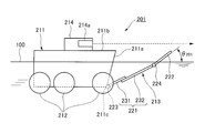
- the amphibian 201 is provided with a flap (plate-like member) 213 for making it easier to receive lift from water when traveling on the water.
- the flaps 213 can be deployed and stored with respect to the vehicle main body 211 (retractable flaps), and the lower flap 221 stored so as to approach (contact) the front surface 211 a of the vehicle main body 211 It roughly comprises an upper flap 222 housed so as to be close to (in contact with) the upper surface 211 b.
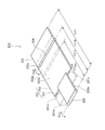
- the lower flaps 221 are roughly configured of a first lower flap 231 and a second lower flap 232 that can slide relative to each other.
- the flap length length in the direction in which the flap (lower flap 221) extends orthogonal to the vehicle width direction) is configured to be variable.
- the first lower flap 231 is a substantially rectangular plate-like member having a narrow width, and the lower end edge 231 a is connected to the lower end edge 211 c on the front side in the traveling direction of the vehicle body 211 via the hinge 223.
- the first lower flap 231 is mechanically connected to a first flap drive device 241 (see FIG. 11) for rotating the first lower flap 231 with respect to the vehicle body 211.
- the vehicle body 211 is rotated about a rotation axis C 201 extending in the vehicle width direction.
- the second lower flap 232 is a wide, substantially rectangular plate-like member, and the rear surface 232 a is in contact with the front surface 231 b of the first lower flap 231 and is slidably connected to the first lower flap 231 It is done.
- the second lower flap 232 is mechanically connected to a second flap drive 242 (see FIG. 11) for sliding the second lower flap 232 relative to the first lower flap 231.
- the first lower flap 231 is slid in the V201 axial direction (a direction in which the lower flap 221 (the first lower flap 231 and the second lower flap 232 extend perpendicularly to the vehicle width direction)) It has become.
- the lower flap 221 is substantially similar to the conventional one in a short state (in FIG. 10, a state shown by a two-dot chain line) in which the second lower flap 232 is stored so as to overlap the first lower flap 231.
- a short state in FIG. 10, a state shown by a two-dot chain line
- the long state which has the same flap length L 221A and is developed so that the second lower flap 232 is offset with respect to the first lower flap 231.
- the upper flap 222 is a substantially rectangular plate-like member, and the lower end 222a thereof is connected to the upper end 232b of the second lower flap 232 via the hinge 224.
- the upper flap 222 is mechanically connected to a third flap driving device 243 (see FIG. 11) for rotating the upper flap 222 with respect to the second lower flap 232, and the lower flap 221 (see FIG.
- the second lower flap 231) is rotated about a rotation axis C 202 extending in the vehicle width direction.
- the amphibian 201 is provided with a control device 244 for controlling the operation (deployment and storage) of the flap 213.
- the controller 244 is electrically connected to the first flap drive 241, the second flap drive 242, and the third flap drive 243, respectively, and the first flap drive 241, the second The drive of the flap drive 242 and the third flap drive 243 can be controlled independently.
- various drive sources and mechanisms can be adopted as in the first embodiment. .
- the amphibious vehicle 201 includes a movement state detection device 245 capable of detecting the movement state (such as waterborne or land traveling) of the amphibious vehicle 201, and an amphibious vehicle during seaborne navigation.
- a navigation state detection device 246 capable of detecting the navigation state of 201 is provided.
- the movement state detection means 245 and the navigation state detection device 246 are electrically connected to the control device 244, respectively, and the control device 244 selects the first based on the detection results of the movement state detection 245 and the navigation state detection device 246.
- the drive of the flap drive 241, the second flap drive 242 and the third flap drive 243 are controlled.
- various sensors and the like can be adopted as in the first embodiment.
- the flap 213 in the fully stored state is stored so that the lower flap 221 approaches the front surface 211 a of the vehicle main body 211 in the short state, and the upper flap 222 is stored such that the upper flap 211 approaches the upper surface 211 b of the vehicle main body 211 It is.
- the movement state detection device 245 starts the amphibian 201 from the land traveling state. It detects that it has transitioned to the surface navigation state (see FIGS. 8 and 11).
- the amphibian 201 immediately after the amphibian 201 moves from the land traveling state to the surface navigation state, the amphibian 201 is in the deep floating state of the draft, so that the navigation state detection device 246 operates the navigation of the amphibian 201 It detects that the state is a floating state.
- control device 244 controls the first flap drive device 241, the second flap drive device 242, and the third flap drive device 243 based on the detection results of the movement state detection device 245 and the navigation state detection device 246. Are respectively driven to transform the flaps 213 from the fully stored state to the fully expanded state.
- the flap 213 in the fully deployed state is deployed such that the lower flap 221 is separated from the front surface 211 a of the vehicle main body 211 in the elongated state, and the upper flap 222 is deployed such that it is separated from the upper surface 211 b of the vehicle main body 11 is there.
- the lower flap 221 (first lower flap 231) is moved from the front surface 211a of the vehicle main body 211 by the first flap drive device 241. While being deployed apart, the second lower flap 232 is deployed by the second flap drive 242 to be shifted relative to the first lower flap 231, and the upper flap 222 is deployed by the third flap drive 243. It is developed away from the top surface 211 b of the main body 211.
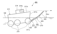
- the navigation state detection device 246 causes the navigation state of the amphibious vehicle 201 to transition from the floating state to the sliding state. To detect (see FIGS. 9 and 11).
- control device 244 drives only the second flap drive device 242, and transforms the flap 213 from the fully expanded state to the partially expanded state (partially stored state).
- the flap 213 in the partially expanded state (partially stored state) is expanded so that the lower flap 221 is separated from the front surface 211 a of the vehicle body 211 in the short state, and expanded so that the upper flap 222 is separated from the upper surface 211 b of the vehicle body 211 It is in a state of being
- the second lower flap 232 with the lower flap 221 (the first lower flap 231) and the upper flap 222 still unfolded. are stored by the second flap drive 242 so as to overlap the first lower flap 231.
- the navigation state detection device 246 causes the navigation state of the amphibian 201 to shift from the sliding state to the floating state. Detects that (see FIGS. 8 and 11).
- control device 244 drives only the second flap drive device 242 based on the detection result of the navigation state detection device 246, and transforms the flap 213 from the partially expanded state (partially stored state) to the fully expanded state. .
- the second lower flap 232 is the second lower flap 221 (the first lower flap 231) as it is unfolded.
- the flap drive device 242 is deployed so as to be offset with respect to the first lower flap 231.
- the movement state detection device 245 causes the amphibian 201 to move from the sea state to the land. It is detected that the vehicle has shifted to the traveling state (see FIGS. 7 and 11).
- control device 244 drives the first flap drive device 241, the second flap drive device 242 and the third flap drive device 243 based on the detection result of the movement state detection device 245, and the flap Transform 213 from the fully deployed state to the fully stowed state.
- the second lower flap 232 is stored so as to overlap the first lower flap 231 by the second flap drive device 242.
- the lower flap 221 (first lower flap 231) is stored by the first flap drive device 241 so as to be close to the front surface 211a of the vehicle main body 211, and the upper flap 222 by the third flap drive device 243. It is stored so as to be close to the upper surface 211 b of the vehicle main body 211.
- the flap length L 221B of the lower flap 221 (long state) It is possible to set the flap length L 213 of the flap 213 (in the fully expanded state) longer than that of the conventional one (see FIG. 10).
- the amphibian 201 is more susceptible to the lift from the water when traveling on the water, so it is more efficient than the conventional one. It is possible to shift from the floating state to the sliding state and move quickly to the destination.
- the contact angle ⁇ 201 between the flap 213 and the water surface (draft line) 100 can be set smaller than that of the conventional one by providing the long flap 213. Yes (see Figure 8).
- the amphibian 201 travels while reducing the water resistance more than conventional ones while traveling on the water. Therefore, it is possible to shift from the floating state to the sliding state more efficiently and to move to the destination faster than the conventional one.
- the flap length L 221A of the lower flap 221 in the short length state is substantially the same as the conventional one. It can be set to the same length (see FIGS. 7 and 10).
- the lower flap 221 in the short state is set to the flap length L 221A substantially equivalent to that of the conventional one, the lower flap 221 (first lower flap does not block the visibility of the driver's seat 214 from the car window 214a.
- the upper flap 222 can be stored on the upper surface of the vehicle body 11 without obstructing the view from the driver's seat 14 (car window 14a). It can be stored close to 11b.
- the lower flap 221 can be stored so as to be close to the front surface 211 a of the vehicle main body 211. It is possible to travel on land (rough land, steps, etc.) without bringing the lower flap 221) into contact with the steps, etc.
- the lower flap 221 (flap 213) is configured to have a variable flap length, when the navigation state of the amphibious vehicle 201 is shifted to the sliding state.
- the amount D 201 of protrusion of the flap 213 protruding from the water surface (the water line) 100 can be suppressed (see FIG. 9).
- the amphibian 201 can travel while reducing the resistance of the air while traveling on the water, so the efficiency in the sliding state is improved. You can travel quickly to your destination.
- the amphibious vehicle 201 even if the front part of the vehicle main body 211 inclines upward (vertically upward) in the sliding state, the protrusion amount D 201 of the flap 213 from the water surface 100 is suppressed. As a result, it is possible to ensure good visibility in the horizontal direction from the car window 214a of the driver's seat 214 (see FIG. 9).
- the lower flaps 221 are roughly configured of a first lower flap 231 and a second lower flap 232 that can slide relative to each other, and the sliding of the first lower flap 231 and the second lower flap 232
- the flap length of the lower flap 221 (flap 213) is configured to be variable.
- the present invention is not limited to the configuration of this embodiment.
- the lower flap is composed of a plurality of (for example, three) flaps (plate-like members) that can be rotated relative to each other, and the flap length of the lower flap (flap) can be varied by rotating the plurality of flaps. You may configure.
- the lengths in the vehicle width direction of the first lower flap 231 and the second lower flap 232 are formed differently,
- the lower flap 221 is formed in a substantially T-shape, and a notch 221 c is provided in the lower flap 221.
- the present invention is not limited to the configuration of this embodiment.
- the lengths in the vehicle width direction of the first lower flap and the second lower flap may be formed to be substantially the same to the extent that interference with the wheel is avoided, or in a substantially T shape (vehicle width
- the notches of the lower flap, which are formed in different lengths in the direction may be configured to be able to be closed when traveling on water.
- the movement state detection device 245 detects the transition state
- the control device 244 detects the movement state detection device 245.
- the drive of the first flap drive device 241, the second flap drive device 242 and the third flap drive device 243 is controlled based on the detection result of the above.
- the present invention is not limited to the configuration of this embodiment.
- control device may control the drive of the first flap drive device, the second flap drive device and the third flap drive device based on the operation of the switch which is the movement state detection device, and
- the movement state detection device can predict the transition of the movement state of the amphibious vehicle, and the control device is the first flap drive device before the movement state transition of the amphibious vehicle (immediately), the second flap
- the drive of the drive unit and the third flap drive unit may be controlled. According to these configurations, for example, it is also possible to store the flap in a state where the amphibian floats on water.
- the flap length of each of the lower flap and the upper flap may be configured to be variable by combining the first embodiment and the second embodiment. It goes without saying that the amphibious vehicle provided with such a storage type flap has the same function and effect as the amphibious vehicle 1 according to the first embodiment and the second embodiment.
Abstract
The present invention enables both enlargement and suitable storage of a collapsible flap. An amphibious vehicle (1) is configured with a flap (13) for receiving lift from water while navigating on water, said flap being provided so as to be deployable and storable to the front vis-à-vis the direction of travel of a vehicle body (11). The flap (13) has a lower flap (21) stored near a front face (11a) of the vehicle body (11) and an upper flap (22) stored near an upper face (11b) of the vehicle body (11). The lower flap (21) and/or upper flap (22) has a first flap member (31) and a second flap member (32) and is configured so as to be variable in flap length (L13) in the direction perpendicular to the vehicle width.
Description
本発明は、水陸両用車に関する。
The present invention relates to an amphibian.
水上および陸上における移動が可能な水陸両用車は、水難救助車や災害対策車両などとして使われることがあり、このような水陸両用車には、目的地へ早く到着することが求められている。そこで、例えば、水陸両用車にフラップを設けることにより、水上航行時の移動速度を増加し、目的地までの移動時間(水上航行の移動時間)を短縮することができる。
An amphibious vehicle capable of traveling on water and on land may be used as a water rescue vehicle or a disaster countermeasure vehicle, and such an amphibious vehicle is required to arrive early at a destination. Therefore, for example, by providing the amphibian with a flap, it is possible to increase the moving speed at the time of waterborne navigation and shorten the traveling time to the destination (moving time of the waterborne navigation).
ここで、フラップは、水陸両用車の水上航行時において水から揚力を受け易くするための板状部材であり、水陸両用車の進行方向前方側へ向って鉛直方向上側に傾斜して設けられ、水面と接触する角度(接触角度)が小さく設定された面(フラップ面)を有する。フラップが設けられた水陸両用車は、水上航行時において喫水の深い浮航状態から喫水の浅い滑走状態へ移行して水上を航行することができるようになるので、水上航行時の移動速度を増加することができる。
Here, the flap is a plate-like member for making it easier to receive lift from water when traveling on an amphibious vehicle, and the flap is provided obliquely upward in the forward direction of the traveling direction of the amphibious vehicle, It has a surface (flap surface) where the angle of contact with the water surface (contact angle) is set small. An amphibious vehicle equipped with flaps can shift from a deep draft of draft to a shallow gliding draft of a draft while sailing on the water, thus increasing the moving speed when sailing on the water can do.
フラップには、車両本体の進行方向前方側において展開および収納可能に設けられる収納式フラップがある。収納式フラップを採用した水陸両用車は、駆動機構によって当該フラップを車両本体から離れるように展開することにより、水上航行時においては滑走状態で航行することができ、駆動機構によって当該フラップを車両本体に近接するように収納することにより、陸上走行時においてはフラップと段差等との接触を回避して走行することができる(例えば、特許文献1参照)。
The flaps include retractable flaps that can be deployed and retracted on the forward side of the vehicle body in the traveling direction. An amphibious vehicle adopting a storage type flap can be navigated in a sliding state during waterborne navigation by expanding the flap away from the vehicle body by the drive mechanism, and the flap can be moved by the drive mechanism to the vehicle body When traveling on land, the vehicle can travel while avoiding contact between the flap and a step or the like (for example, see Patent Document 1).
このような収納式フラップを採用した水陸両用車において、水上航行の移動時間を更に短縮することが求められた場合には、収納式フラップを長大化することにより、水上航行時において水からの揚力を更に受け易いものとし、浮航状態から滑走状態へ効率的に移行することができるようになる。
In an amphibious vehicle adopting such a storage type flap, when it is required to further shorten the traveling time of the water navigation, the lift from the water during the water surface navigation can be achieved by lengthening the storage type flap. Furthermore, it is possible to shift from the floating state to the sliding state efficiently.
しかし、車両本体の上面から突出して運転席が設けられた水陸両用車等においては、収納式フラップを収納するスペースが制限されており、当該収納式フラップを適切に収納することができないことがある。つまり、長大化した収納フラップが収納時に運転席等と干渉してしまう場合には、当該水陸両用車のフラップを長大化することができない。
However, in an amphibious vehicle or the like provided with a driver's seat projecting from the upper surface of the vehicle body, the space for storing the storage type flap is limited, and the storage type flap may not be properly stored. . That is, when the elongated storage flap interferes with the driver's seat or the like at the time of storage, the flap of the amphibious vehicle can not be elongated.
本発明は上記問題に鑑みてなされたもので、フラップを長大化すると共に適切に収納することができるようにすることを目的とする。
The present invention has been made in view of the above problems, and it is an object of the present invention to make a flap longer and to be able to be stored properly.
上記課題を解決する第一の発明に係る水陸両用車は、水上航行時に水から揚力を受けるためのフラップが車両本体の進行方向前方側において展開および収納可能に設けられて成る水陸両用車において、前記フラップは、前記車両本体の前面に近接するように収納される下段フラップと、前記車両本体の上面に近接するように収納される上段フラップとを有するものであり、前記下段フラップおよび前記上段フラップの少なくとも一方は、第一のフラップ部材と第二のフラップ部材とを有して車両幅方向と直交する方向におけるフラップ長さを可変に構成されて成るものであることを特徴とする。
An amphibious vehicle according to a first aspect of the present invention for solving the above problems is an amphibious vehicle provided with a flap for receiving lift from water when traveling on water, which can be deployed and stored on the forward side in the traveling direction of the vehicle body. The flap has a lower flap stored so as to be close to the front of the vehicle main body and an upper flap stored so as to be close to the upper surface of the vehicle main body, and the lower flap and the upper flap At least one of the first and second flap members is characterized in that the flap length in the direction orthogonal to the vehicle width direction is variable.
上記課題を解決する第二の発明に係る水陸両用車は、第一の発明に係る水陸両用車において、前記第一のフラップ部材と前記第二のフラップ部材とは、互いに摺動可能に接続されて成るものであり、前記フラップは、前記第一のフラップ部材と前記第二のフラップ部材との摺動動作により、前記フラップ長さを可変に構成されるものであることを特徴とする。
An amphibian according to a second aspect of the present invention for solving the above problems is the amphibian according to the first aspect, wherein the first flap member and the second flap member are slidably connected to each other. The flap is characterized in that the flap length is made variable by the sliding movement of the first flap member and the second flap member.
上記課題を解決する第三の発明に係る水陸両用車は、第一の発明に係る水陸両用車において、前記第一のフラップ部材と前記第二のフラップ部材とは、互いに回転可能に接続されて成るものであり、前記フラップは、前記第一のフラップ部材と前記第二のフラップ部材との回転動作により、前記フラップ長さを可変に構成されるものであることを特徴とする。
An amphibian according to a third aspect of the present invention for solving the above problems is the amphibian according to the first aspect, wherein the first flap member and the second flap member are rotatably connected to each other. The flap is characterized in that the flap length is made variable by the rotational movement of the first flap member and the second flap member.
上記課題を解決する第四の発明に係る水陸両用車は、第一から第三のいずれか一つの発明に係る水陸両用車において、前記フラップを展開および収納する駆動装置と、水上を移動する際の航行状態を検出可能な航行状態検出装置と、前記航行状態検出装置の検出結果に基づいて、前記駆動装置の駆動を制御する制御装置とを備えたことを特徴とする。
An amphibious vehicle according to a fourth aspect of the present invention for solving the above-mentioned problems is the amphibian according to any one of the first to third inventions, wherein the drive for expanding and storing the flap, and movement on the water A navigation state detection device capable of detecting the navigation state of the vehicle, and a control device for controlling driving of the drive device based on a detection result of the navigation state detection device.
上記課題を解決する第五の発明に係る水陸両用車は、第四の発明に係る水陸両用車において、前記制御装置は、前記航行状態検出装置によって航行状態が浮航状態であることが検出されると、前記フラップ長さが長くなるように前記駆動装置を動作し、前記航行状態検出装置によって航行状態が滑走状態であることが検出されると、前記フラップ長さが短くなるように前記駆動装置を動作するものであることを特徴とする。
An amphibious vehicle according to a fifth aspect of the present invention for solving the above-mentioned problems is the amphibious vehicle according to the fourth aspect, wherein in the control device, the navigation state detection device detects that the navigation state is a floating state The driving device is operated to increase the flap length, and the driving device is operated to reduce the flap length when the navigation state detection device detects that the navigation state is the sliding state. The apparatus is characterized in that it operates.
第一の発明に係る水陸両用車によれば、フラップを長大化すると共に適切に収納することができる。また、フラップを長大化することにより、水陸両用車の水上航行時において揚力を増大できるため効率的に滑走領域に達することができ、さらに、長大化したフラップと水面(喫水線)との接触角度を小さく設定することにより、水陸両用車の水上航行時において抵抗を小さくできるためより効率的に滑走領域に達することができる。
According to the amphibious vehicle of the first aspect of the invention, the flap can be lengthened and appropriately stored. In addition, by extending the flap, lift force can be increased during navigation on the water of the amphibious vehicle, so that the sliding area can be efficiently reached. Furthermore, the contact angle between the elongated flap and the water surface (water line) By setting it small, resistance can be reduced when traveling on the water of the amphibious vehicle, and the sliding area can be reached more efficiently.
第二の発明に係る水陸両用車によれば、長大化すると共に適切に収納することができるフラップを簡易な構成とすることができる。
According to the amphibious vehicle of the second aspect of the invention, it is possible to make the flaps which can be stored in an appropriate size with a simple structure.
第三の発明に係る水陸両用車によれば、長大化すると共に適切に収納することができるフラップを簡易な構成とすることができる。
According to the amphibious vehicle of the third invention, it is possible to make the flap which can be stored in an appropriate size as well as to be simple.
第四の発明に係る水陸両用車によれば、水陸両用車の航行状態(浮航状態、滑走状態等)に応じて、フラップを適切に展開および収納することができる。
According to the amphibian of the fourth aspect of the invention, the flap can be appropriately deployed and stored according to the navigation state (floating state, sliding state, etc.) of the amphibian.
第五の発明に係る水陸両用車によれば、水陸両用車の航行状態が浮航状態または滑走状態である場合において、フラップをそれぞれ適切に展開および収納し、水上を効率的に航行することができる。
According to the amphibious vehicle of the fifth invention, when the navigation condition of the amphibious vehicle is in a floating state or a sliding state, it is possible to appropriately deploy and store the flaps and efficiently navigate the water. it can.
以下に、本発明に係る水陸両用車の実施例について、添付図面を参照して詳細に説明する。もちろん、本発明は以下の実施例に限定されず、本発明の趣旨を逸脱しない範囲で各種変更が可能であることは言うまでもない。
Hereinafter, embodiments of an amphibian according to the present invention will be described in detail with reference to the attached drawings. Of course, the present invention is not limited to the following embodiments, and it goes without saying that various modifications can be made without departing from the scope of the present invention.
[実施例1]
本発明の実施例1に係る水陸両用車の構造について、図1から図5を参照して説明する。 Example 1
The structure of the amphibian according to the first embodiment of the present invention will be described with reference to FIGS. 1 to 5.
本発明の実施例1に係る水陸両用車の構造について、図1から図5を参照して説明する。 Example 1
The structure of the amphibian according to the first embodiment of the present invention will be described with reference to FIGS. 1 to 5.
図1に示すように、水陸両用車1は、車両本体11の下部に装輪(または装軌)12を備えており、この装輪12を図示しない駆動源によって駆動することにより、陸上を走行することができるようになっている。また、水陸両用車1は、図示しないプロペラを備えており、このプロペラを図示しない駆動源によって駆動することにより、水上を航行することができるようになっている(図2参照)。つまり、水陸両用車1は、水上および陸上における移動が可能なものである。
As shown in FIG. 1, the amphibious vehicle 1 is equipped with a wheeled (or tracked) 12 at the lower part of the vehicle body 11, and travels on the land by driving the wheeled wheel 12 by a drive source (not shown). It can be done. In addition, the amphibious vehicle 1 is provided with a propeller (not shown), and can be navigated on the water by driving the propeller with a driving source (not shown) (see FIG. 2). That is, the amphibian 1 is capable of traveling on water and on land.
図2に示すように、水陸両用車1には、水上航行時において水から揚力を受け易くするためのフラップ(板状部材)13が車両本体11の進行方向前方側(図2においては、右方側)に設けられている。よって、水陸両用車1は、水上航行時においてフラップ13によって水から揚力を受けることにより、その航行状態を喫水の深い浮航状態から喫水の浅い滑走状態へと移行させて水上を航行することができる。
As shown in FIG. 2, in the amphibious vehicle 1, a flap (plate-like member) 13 for making it easy to receive lift from water when traveling on water is the forward side in the traveling direction of the vehicle main body 11 (in FIG. Provided on the other side). Therefore, the amphibious vehicle 1 travels on the water by transferring its sailing state from the deep floating state of the draft to the shallow sliding state of the draft by receiving lift from the water by the flap 13 at the time of marine navigation it can.
図1および図2に示すように、フラップ13は、車両本体11に対して展開および収納可能なもの(収納式フラップ)であり、車両本体11の前面11aに近接する(接する)ように収納される下段フラップ21と、車両本体11の上面11bに近接する(接する)ように収納される上段フラップ22とから概略構成されている。
As shown in FIG. 1 and FIG. 2, the flap 13 is one that can be deployed and stored in the vehicle body 11 (retractable flap), and is stored so as to approach (contact) the front surface 11 a of the vehicle body 11 And an upper flap 22 housed so as to approach (contact) the upper surface 11 b of the vehicle main body 11.
図1、図2および図4に示すように、下段フラップ21は、略T字形状の板状部材であり、その幅の狭い下端縁21aがヒンジ23を介して車両本体11の進行方向前方側における下端縁11cと接続されて成る。また、下段フラップ21は、当該下段フラップ21を車両本体11に対して回転動作するための第一のフラップ駆動装置41(図5参照)と機械的に接続されており、車両本体11に対して車両幅方向に延在する回転軸C1周りに回転されるようになっている。
As shown in FIG. 1, FIG. 2 and FIG. 4, the lower flap 21 is a substantially T-shaped plate-like member, and the lower end edge 21a with its narrow width is on the front side in the traveling direction of the vehicle body 11 via the hinge 23. Is connected to the lower end edge 11c. The lower flap 21 is mechanically connected to a first flap drive device 41 (see FIG. 5) for rotating the lower flap 21 with respect to the vehicle main body 11. It is adapted to be rotated to the rotation axis C 1 around which extends in the vehicle width direction.
図4に示すように、上段フラップ22は、互いに摺動可能な第一の上段フラップ31と第二の上段フラップ32とから概略構成されており、第一上段フラップ31と第二上段フラップ32との摺動動作により、そのフラップ長さ(車両幅方向と直交して当該フラップ(上段フラップ22)が延在する方向における長さ)が可変に構成されている。
As shown in FIG. 4, the upper flap 22 is roughly configured of a first upper flap 31 and a second upper flap 32 that can slide relative to each other, and the first upper flap 31 and the second upper flap 32 The flap length (the length in the direction in which the flap (the upper flap 22 extends perpendicularly to the vehicle width direction) is variably configured by the sliding operation of the above.
第一上段フラップ31は、略長方形状の板状部材であり、その下端縁31aがヒンジ24を介して下段フラップ21における幅の広い上端縁21bと接続されて成る。また、第一上段フラップ31は、当該第一上段フラップ31を下段フラップ21に対して回転動作するための第二のフラップ駆動装置42(図5参照)と機械的に接続されており、下段フラップ21に対して車両幅方向に延在する回転軸C2周りに回転されるようになっている。
The first upper flap 31 is a substantially rectangular plate-like member, and the lower end edge 31 a thereof is connected to the wide upper end edge 21 b of the lower flap 21 through the hinge 24. The first upper flap 31 is mechanically connected to a second flap drive device 42 (see FIG. 5) for rotating the first upper flap 31 with respect to the lower flap 21, and the lower flap is It is adapted to be rotated to the rotation axis C 2 around which extends in the vehicle width direction with respect to 21.
第二上段フラップ32は、略長方形状の板状部材であり、その後面32aが第一上段フラップ31の前面31bと接して第一上段フラップ31に対して摺動可能に接続されて成る。また、第二上段フラップ32は、第二上段フラップ32を第一上段フラップ31に対して摺動動作するための第三のフラップ駆動装置43(図5参照)と機械的に接続されており、第一上段フラップ31に対してV1軸方向(車両幅方向と直交して上段フラップ22(第一上段フラップ31および第二上段フラップ32)が延在する方向)に摺動されるようになっている。
The second upper flap 32 is a substantially rectangular plate-like member, and the rear surface 32 a is in contact with the front surface 31 b of the first upper flap 31 and slidably connected to the first upper flap 31. The second upper flap 32 is mechanically connected to a third flap drive device 43 (see FIG. 5) for sliding the second upper flap 32 relative to the first upper flap 31. The first upper flap 31 is slid in the V1 axis direction (the direction in which the upper flap 22 (the first upper flap 31 and the second upper flap 32) extends orthogonal to the vehicle width direction) There is.
よって、上段フラップ22は、第二上段フラップ32が第一上段フラップ31に対して重なり合うように収納された短尺状態(図5においては、二点鎖線で示す状態)において、従来のものと略同等のフラップ長さL22Aを有し、第二上段フラップ32が第一上段フラップ31に対してずれるように展開された長尺状態(図5においては、実線で示す状態)において、従来のものよりも長いフラップ長さL22Bを有する。
Therefore, the upper flap 22 is substantially equivalent to the conventional one in a short state in which the second upper flap 32 is stored so as to overlap the first upper flap 31 (in the state shown by the two-dot chain line in FIG. 5). has a flap length L 22A, (in FIG. 5, the state shown by the solid line) long state of being expanded to the second upper flap 32 is displaced with respect to the first upper flap 31 in, than the conventional It also has a long flap length L 22B .
図5に示すように、水陸両用車1には、フラップ13の動作(展開および収納)を制御するための制御装置44が設けられている。制御装置44は、第一のフラップ駆動装置41、第二のフラップ駆動装置42および第三のフラップ駆動装置43とそれぞれ電気的に接続されており、これら第一のフラップ駆動装置41、第二のフラップ駆動装置42および第三のフラップ駆動装置43の駆動をそれぞれ独立して制御することができるようになっている。
As shown in FIG. 5, the amphibian 1 is provided with a control device 44 for controlling the operation (deployment and storage) of the flap 13. The control device 44 is electrically connected to the first flap drive device 41, the second flap drive device 42 and the third flap drive device 43, respectively, and the first flap drive device 41, the second The drive of the flap drive 42 and the third flap drive 43 can be controlled independently.
ここで、第一のフラップ駆動装置41、第二のフラップ駆動装置42および第三のフラップ駆動装置43としては、種々の駆動源および機構等をそれぞれ採用することができる。例えば、駆動源としての油圧シリンダ(伸縮部材)を部材間(車両本体11と下段フラップ21との間、下段フラップ21と第一上段フラップ31との間、第一上段フラップ31と第二上段フラップ32との間)に設けることにより、油圧シリンダの伸縮動作を利用して部材間の回転動作および摺動動作を行うことができる。また、例えば、駆動源としてのモータ(動力発生機)およびギヤ機構(またはワイヤ機構)を部材間(車両本体11と下段フラップ21との間、下段フラップ21と第一上段フラップ31との間、第一上段フラップ31と第二上段フラップ32との間)に設けることにより、モータの回転動作を利用して部材間の回転動作および摺動動作を行うことができる。
Here, as the first flap drive device 41, the second flap drive device 42 and the third flap drive device 43, various drive sources and mechanisms can be adopted, respectively. For example, a hydraulic cylinder (a telescopic member) as a drive source may be inserted between the members (between the vehicle main body 11 and the lower flap 21, between the lower flap 21 and the first upper flap 31, the first upper flap 31 and the second upper flap) By providing them between 32 and 32, it is possible to perform rotational operation and sliding operation between the members by utilizing the extension and contraction operation of the hydraulic cylinder. Further, for example, between the members (between the vehicle main body 11 and the lower flap 21, between the lower flap 21 and the first upper flap 31), the motor (power generator) and the gear mechanism (or wire mechanism) as drive sources By providing the first upper flap 31 and the second upper flap 32), rotational movement and sliding movement between members can be performed by utilizing the rotational movement of the motor.
また、図5に示すように、水陸両用車1には、当該水陸両用車1の移動状態(水上航行または陸上走行等)を検出可能な移動状態検出装置45と、水上航行時における水陸両用車1の航行状態を検出可能な航行状態検出装置46とが設けられている。移動状態検出手段45および航行状態検出装置46は、制御装置44とそれぞれ電気的に接続されており、制御装置44は、移動状態検出45および航行状態検出装置46の検出結果に基づいて、第一のフラップ駆動装置41、第二のフラップ駆動装置42および第三のフラップ駆動装置43の駆動をそれぞれ制御するようになっている。
Further, as shown in FIG. 5, the amphibious vehicle 1 includes a movement condition detection device 45 capable of detecting the movement condition (water navigation or land traveling, etc.) of the amphibian 1, and the amphibious vehicle at the time of water navigation. A navigation state detection device 46 capable of detecting one navigation state is provided. The movement state detection means 45 and the navigation state detection device 46 are electrically connected to the control device 44 respectively, and the control device 44 performs the first operation based on the detection results of the movement state detection 45 and the navigation state detection device 46. The drive of the flap drive 41, the second flap drive 42 and the third flap drive 43 are controlled.
ここで、移動状態検出装置45および航行状態検出装置46としては、種々のセンサ等を採用することができる。例えば、移動状態検出装置45としては、乗員が操作するスイッチや水陸両用車1が進水したことを検出する水圧センサ等を採用することができ、航行状態検出装置46としては、水上航行における移動速度を検出する速度センサ等を採用することができる。なお、航行状態検出装置46として速度センサを採用した場合には、制御装置44は、水陸両用車1の水上航行時における移動速度が所定値未満である場合には、水陸両用車1が浮航状態であると判断し、水陸両用車1の水上航行時における移動速度が所定値以上である場合には、水陸両用車1が滑走状態であると判断する。
Here, various sensors or the like can be adopted as the movement state detection device 45 and the navigation state detection device 46. For example, as the movement state detection device 45, a switch operated by a passenger, a water pressure sensor for detecting that the amphibious vehicle 1 has been launched can be adopted, and as the navigation state detection device 46, movement in water navigation A speed sensor or the like that detects the speed can be employed. When the speed sensor is adopted as the navigation state detection device 46, the control device 44 lifts the amphibian 1 when the movement speed of the amphibian 1 during the water navigation is less than a predetermined value. It is determined that the vehicle is in the state, and if the traveling speed of the amphibian 1 while traveling on the water is equal to or more than a predetermined value, it is determined that the amphibian 1 is in the sliding state.
本発明の実施例1に係る水陸両用車の動作について、図1から図5を参照して説明する。
The operation of the amphibian according to the first embodiment of the present invention will be described with reference to FIGS. 1 to 5.
まず、水陸両用車1が図示しない動力源によって装輪12を駆動して陸上を走行しているとき、フラップ13は全収納状態にある(図1参照)。
First, when the amphibian 1 is driven on the land by driving the wheel 12 with a power source (not shown), the flap 13 is in the fully stored state (see FIG. 1).
全収納状態のフラップ13は、下段フラップ21が車両本体11の前面11aに近接するように収納されると共に、上段フラップ22が短尺状態で車両本体11の上面11bに近接するように収納された状態である。
The flap 13 in the fully stored state is stored such that the lower flap 21 approaches the front surface 11a of the vehicle main body 11, and the upper flap 22 is stored so as to approach the upper surface 11b of the vehicle main body 11 in the short state. It is.
続いて、例えば、水陸両用車1が進水して図示しない動力源によって図示しないプロペラを駆動して水上を航行すると、移動状態検出装置45は、水陸両用車1の移動状態が陸上走行状態から水上航行状態へと移行したことを検出する(図2および図5参照)。
Subsequently, for example, when the amphibian 1 is launched and the propeller (not shown) is driven by the power source (not shown) to travel on the water, the movement state detection device 45 detects that the amphibian 1 moves from the land state It detects that it has transitioned to the surface navigation state (see FIGS. 2 and 5).
また、水陸両用車1が陸上走行状態から水上航行状態へと移行した直後は、当該水陸両用車1は喫水の深い浮航状態であるので、航行状態検出装置46は、水陸両用車1の航行状態が浮航状態であることを検出する。
In addition, immediately after the amphibian 1 is transferred from the land traveling state to the water navigation state, the amphibian 1 is in the deep floating state of the draft, so that the navigation state detection device 46 operates the navigation of the amphibian 1 It detects that the state is a floating state.
よって、制御装置44は、これら移動状態検出装置45および航行状態検出装置46の検出結果に基づいて、第一のフラップ駆動装置41と第二のフラップ駆動装置42と第三のフラップ駆動装置43とをそれぞれ駆動し、フラップ13を全収納状態から全展開状態へ変態する。
Therefore, the control unit 44 controls the first flap drive unit 41, the second flap drive unit 42 and the third flap drive unit 43 based on the detection results of the movement state detection unit 45 and the navigation state detection unit 46. Are respectively driven to transform the flaps 13 from the fully stored state to the fully expanded state.
全展開状態のフラップ13は、下段フラップ21が車両本体11の前面11aから離れるように展開されると共に、上段フラップ22が長尺状態で車両本体11の上面11bから離れるように展開された状態である。
In the fully deployed state, the lower flap 21 is deployed away from the front surface 11 a of the vehicle body 11 and the upper flap 22 is deployed away from the upper surface 11 b of the vehicle body 11 in the elongated state. is there.
つまり、水陸両用車1が陸上走行状態から水上航行状態(浮航状態)へ移行すると、下段フラップ21が第一のフラップ駆動装置41によって車両本体11の前面11aから離れるように展開されると共に、第一上段フラップ31が第二のフラップ駆動装置42によって車両本体11の上面11bから離れるように展開され、第二上段フラップ32が第三のフラップ駆動装置43によって第一上段フラップ31に対してずれるように展開される。
That is, when the amphibious vehicle 1 shifts from the land traveling state to the floating navigation state (floating state), the lower flap 21 is expanded by the first flap drive device 41 so as to be away from the front surface 11a of the vehicle body 11; The first upper flap 31 is developed away from the top surface 11b of the vehicle body 11 by the second flap drive 42, and the second upper flap 32 is displaced relative to the first upper flap 31 by the third flap drive 43. To be expanded.
続いて、水陸両用車1が水上航行において増速して浮航状態から滑走状態へ移行すると、航行状態検出装置46は、水陸両用車1の航行状態が浮航状態から滑走状態へと移行したことを検出する(図3および図5参照)。
Subsequently, when the amphibious vehicle 1 accelerates in sea navigation and shifts from the floating state to the sliding state, the navigation state detection device 46 changes the navigation state of the amphibious vehicle 1 from the floating state to the sliding state To detect (see FIGS. 3 and 5).
よって、制御装置44は、この航行状態検出装置46の検出結果に基づいて、第三のフラップ駆動装置43だけを駆動し、フラップ13を全展開状態から部分展開状態(部分収納状態)へ変態する。
Therefore, the control unit 44 drives only the third flap drive unit 43 based on the detection result of the navigation state detection unit 46, and transforms the flap 13 from the fully expanded state to the partially expanded state (partially stored state). .
部分展開状態(部分収納状態)のフラップ13は、下段フラップ21が車両本体11の前面11aから離れるように展開されると共に、上段フラップ22が短尺状態で車両本体11の上面11bから離れるように展開された状態である。
The flap 13 in the partially expanded state (partially stored state) is expanded so that the lower flap 21 is separated from the front surface 11 a of the vehicle body 11 and expanded so that the upper flap 22 is separated from the upper surface 11 b of the vehicle body 11 in a short length state. It is in a state of being
つまり、水陸両用車1が水上航行状態において浮航状態から滑走状態へ移行すると、下段フラップ21および第一上段フラップ31が展開されたままの状態で、第二上段フラップ32が第三のフラップ駆動装置43によって第一上段フラップ31に対して重なり合うように収納される。
That is, when the amphibious vehicle 1 shifts from the floating state to the sliding state in the watercraft navigation state, the second upper flap 32 is driven with the third flap while the lower flap 21 and the first upper flap 31 are unfolded. The device 43 is stored so as to overlap the first upper flap 31.
続いて、水陸両用車1が水上航行において減速して滑走状態から浮航状態へと移行すると、航行状態検出装置46は、水陸両用車1の航行状態が滑走状態から浮航状態へと移行したことを検出する(図2および図5参照)。
Subsequently, when the amphibious vehicle 1 decelerates on the surface navigation and shifts from the sliding state to the floating state, the navigation state detection device 46 changes the navigation state of the amphibious vehicle 1 from the sliding state to the floating state To detect (see FIGS. 2 and 5).
よって、制御装置44は、この航行状態検出装置46の検出結果に基づいて、第三のフラップ駆動装置43だけを駆動し、フラップ13を部分展開状態(部分収納状態)から全展開状態へ変態する。
Therefore, the control unit 44 drives only the third flap drive unit 43 based on the detection result of the navigation state detection unit 46, and transforms the flap 13 from the partially expanded state (partially stored state) to the fully expanded state. .
つまり、水陸両用車1が水上航行状態において滑走状態から浮航状態へ移行すると、下段フラップ21および第一上段フラップ31が展開されたままの状態で、第二上段フラップ32が第三のフラップ駆動装置43によって第一上段フラップ31に対してずれるように展開される。
That is, when the amphibious vehicle 1 shifts from the sliding state to the floating state in the watercraft navigation state, the second upper flap 32 is driven with the third flap while the lower flap 21 and the first upper flap 31 are unfolded. The device 43 is deployed to be offset relative to the first upper flap 31.
続いて、例えば、水陸両用車1が上陸して図示しない動力源によって装輪12を駆動して陸上を走行すると、移動状態検出装置45は、水陸両用車1の移動状態が水上航行状態から陸上走行状態へと移行したことを検出する(図1および図5参照)。
Subsequently, for example, when the amphibian 1 lands and travels on land by driving the wheel 12 with a power source (not shown), the movement state detection device 45 causes the amphibian 1 to move from the sea state to the land It detects that the vehicle has shifted to the traveling state (see FIGS. 1 and 5).
よって、制御装置44は、この移動状態検出装置45の検出結果に基づいて、第一のフラップ駆動装置41と第二のフラップ駆動装置42と第三のフラップ駆動装置43とをそれぞれ駆動し、フラップ13を全展開状態から全収納状態へ変態する。
Therefore, the control device 44 drives the first flap drive device 41, the second flap drive device 42 and the third flap drive device 43 based on the detection result of the movement state detection device 45, and the flap is Transform 13 from the fully developed state to the fully stored state.
つまり、水陸両用車1が水上航行状態(浮航状態)から陸上走行状態へ移行すると、第二上段フラップ32が第三のフラップ駆動装置43によって第一上段フラップ31に対して重なり合うように収納され、下段フラップ21が第一のフラップ駆動装置41によって車両本体11の前面11aに近接するように収納されると共に、第一上段フラップ31(上段フラップ22)が第二のフラップ駆動装置42によって車両本体11の上面11bに近接するように収納される。
That is, when the amphibious vehicle 1 shifts from the waterborne state (floating state) to the land traveling state, the second upper flap 32 is stored by the third flap drive device 43 so as to overlap the first upper flap 31. The lower flap 21 is stored by the first flap drive device 41 so as to be close to the front surface 11a of the vehicle body 11, and the first upper flap 31 (upper flap 22) is moved by the second flap drive device 42. It is stored so as to be close to the upper surface 11 b of 11.
本実施例に係る水陸両用車1によれば、上段フラップ22(フラップ13)がそのフラップ長さを可変に構成されているので、長尺状態の上段フラップ22のフラップ長さL22Bを従来のものよりも長く設定し、全展開状態のフラップ13のフラップ長さL13を従来のものよりも長く設定することができる(図4参照)。このように従来のものよりも長大なフラップ13を備えることにより、水陸両用車1は、水上航行時において従来のものよりも水からの揚力を受け易くなるので、従来のものよりも効率的に浮航状態から滑走状態へと移行して目的地まで早く移動することができる。
According to the amphibious vehicle 1 of the present embodiment, since the upper flap 22 (flap 13) is configured to have a variable flap length, the flap length L 22B of the upper flap 22 in the long state can be The flap length L 13 of the flap 13 in the fully deployed state can be set longer than that of the conventional one (see FIG. 4). By providing the flap 13 which is longer than the conventional one in this manner, the amphibian 1 is more susceptible to the lift from the water when traveling on the water than the conventional one, so it is more efficient than the conventional one. It is possible to shift from the floating state to the sliding state and move quickly to the destination.
また、本実施例に係る水陸両用車1によれば、長大なフラップ13を備えているので、フラップ13と水面(喫水線)100との接触角度θ1を従来のものよりも小さく設定することができる(図2参照)。このようにフラップ13と水面(喫水線)100との接触角度θ1を小さく設定することにより、水陸両用車1は、水上航行時において従来のものよりも水の抵抗をより低減して航行することができるので、従来のものよりもより効率的に浮航状態から滑走状態へ移行して目的地までより早く移動することができる。
Further, according to the amphibian 1 according to this embodiment is provided with the long flap 13, the contact angle theta 1 between the flaps 13 and the water surface (waterline) 100 be set to be smaller than that of the conventional Yes (see Figure 2). Thus, by setting the contact angle θ 1 between the flap 13 and the water surface (draft line) 100 small, the amphibian 1 travels while reducing the water resistance more than conventional ones while traveling on the water. Therefore, it is possible to shift from the floating state to the sliding state more efficiently and to move to the destination faster than the conventional one.
また、本実施例に係る水陸両用車1によれば、上段フラップ22がそのフラップ長さを可変に構成されているので、短尺状態の上段フラップ22のフラップ長さL22Aを従来のものと略同等の長さに設定することができる(図1および図4参照)。このように短尺状態の上段フラップ22を従来のものと略同等のフラップ長さL22Aとすることにより、車両本体11の上面11bから突出して設けられる運転席14等と干渉させることなく、かつ、運転席14の車窓14aからの視界を妨げることなく、上段フラップ22(第一上段フラップ31および第二上段フラップ32)を車両本体11の上面11bに近接するように収納することができる。
Further, according to the amphibious vehicle 1 according to the present embodiment, since the upper flap 22 is configured to have a variable flap length, the flap length L 22A of the upper flap 22 in the short state is substantially the same as that of the conventional one. It can be set to the same length (see FIGS. 1 and 4). By thus setting the upper flap 22 in the short state to a flap length L 22A substantially equivalent to that of the conventional one, without interfering with the driver's seat 14 or the like provided protruding from the upper surface 11 b of the vehicle main body 11 The upper flaps 22 (the first upper flap 31 and the second upper flap 32) can be stored close to the top surface 11b of the vehicle body 11 without obstructing the view of the driver's seat 14 from the car window 14a.
また、本実施例に係る水陸両用車1によれば、短尺状態の上段フラップ22(第一上段フラップ31および第二上段フラップ32)を車両本体11の上面11bに近接するように収納することができるので、下段フラップ21を車両本体11の前面11aに近接するように収納することができる(図1参照)。このように下段フラップ21を車両本体11の前面11aに近接するように収納することにより、水陸両用車1は、陸上走行時においてフラップ13(下段フラップ21)を段差等と接触させることなく、陸上(不整地や段差等)を走行することができる。
Moreover, according to the amphibious vehicle 1 according to the present embodiment, the upper flap 22 (the first upper flap 31 and the second upper flap 32) in the short state can be stored close to the upper surface 11b of the vehicle main body 11 Since it is possible, the lower flap 21 can be stored so as to be close to the front surface 11a of the vehicle main body 11 (see FIG. 1). By accommodating the lower flap 21 close to the front surface 11a of the vehicle body 11 as described above, the amphibian 1 can be used on land without traveling the flap 13 (lower flap 21) with a step or the like when traveling on land. It is possible to travel (rough terrain, steps, etc.).
また、本実施例に係る水陸両用車1によれば、上段フラップ22(フラップ13)がそのフラップ長さを可変に構成されているので、水陸両用車1の航行状態が滑走状態に移行した際には、上段フラップ22(フラップ13)を短尺状態とすることにより、フラップ13の水面(喫水線)100から突出する突出量D1を抑えることができる(図3参照)。このように滑走状態においてフラップ13の水面100からの突出量D1を抑えることにより、水陸両用車1は、水上航行時において空気の抵抗を低減して航行することができるので、滑走状態で効率的に航行して目的地まで早く移動することができる。
Moreover, according to the amphibious vehicle 1 according to the present embodiment, since the upper flap 22 (flap 13) is configured to have a variable flap length, when the navigation state of the amphibious vehicle 1 is shifted to the sliding state , the upper flap 22 (the flap 13) by a short condition, it is possible to suppress the amount of protrusion D 1 projecting from the water surface of the flap 13 (waterline) 100 (see FIG. 3). By suppressing the protrusion amount D 1 of the water surface 100 of the flap 13 in this manner planing state, amphibian 1, it is possible to sail by reducing the resistance of air during water cruising, efficiency planing state You can travel quickly to your destination.
また、本実施例に係る水陸両用車1によれば、滑走状態において車両本体11の前方部が上向き(鉛直方向上側)に傾いたとしても、フラップ13の水面100からの突出量D1を抑えることにより、運転席14の車窓14aから水平方向における視界を良好に確保することができる(図3参照)。
Further, according to the amphibian 1 according to this embodiment, even if the front portion of the vehicle body 11 is inclined upward (upward vertical direction) in planing state, suppressing the protrusion amount D 1 of the water surface 100 of the flap 13 As a result, it is possible to ensure good visibility in the horizontal direction from the car window 14a of the driver's seat 14 (see FIG. 3).
本実施例においては、上段フラップ22を互いに摺動可能な第一上段フラップ31と第二上段フラップ32とから概略構成し、これら第一上段フラップ31と第二上段フラップ32との摺動動作により、上段フラップ22(フラップ13)のフラップ長さを可変に構成している。もちろん、本発明は、本実施例の構成のものに限定されない。
In the present embodiment, the upper flaps 22 are roughly configured of a first upper flap 31 and a second upper flap 32 that can slide relative to each other, and a sliding operation between the first upper flap 31 and the second upper flap 32 The flap length of the upper flap 22 (flap 13) is variable. Of course, the present invention is not limited to the configuration of this embodiment.
例えば、図6に示すように、上段フラップ122を互いに回転可能な第一上段フラップ131と第二上段フラップ132とから概略構成し、これら第一上段フラップ131と第二上段フラップ132との回転動作(第一上段フラップ131に対して第二上段フラップ132を折り畳むように回転すること)により、上段フラップ122(フラップ113)のフラップ長さを可変に構成しても良い。このような構成の収納式フラップ113は、図示しない水陸両用車の車両本体とヒンジ123を介して回転軸C101周りに回転可能に接続される下段フラップ121と、この下段フラップ121とヒンジ124を介して回転軸C102周りに回転可能に接続される第一上段フラップ131と、この第一上段フラップ131とヒンジ125を介して回転軸C103周りに回転可能に接続される第二上段フラップ132とを備える。なお、上述した構成の収納式フラップ113を備えた水陸両用車は、実施例1に係る水陸両用車1と同様の作用効果を奏することは言うまでもない。
For example, as shown in FIG. 6, the upper stage flaps 122 are roughly configured of a first upper stage flap 131 and a second upper stage flap 132 that are rotatable relative to each other, and the rotational movement of the first upper stage flap 131 and the second upper stage flap 132 The flap length of the upper flap 122 (flap 113) may be variably configured by (rotating so as to fold the second upper flap 132 with respect to the first upper flap 131). The storage type flap 113 of such a configuration is connected to the lower flap 121 rotatably connected around the rotation axis C 101 via the hinge 123 and the vehicle body of the amphibious vehicle (not shown), and the lower flap 121 and the hinge 124 A first upper flap 131 rotatably connected about the rotation axis C 102 via the second upper flap 132, and a second upper flap 132 rotatably connected about the rotation axis C 103 via the first upper flap 131 and the hinge 125. And It goes without saying that the amphibious vehicle provided with the storage type flap 113 having the above-described configuration exhibits the same function and effect as the amphibious vehicle 1 according to the first embodiment.
また、本実施例においては、下段フラップ21(下段フラップ121)と装輪12との干渉を回避するために、下段フラップ21を略T字形状に形成して当該下段フラップ21に切り欠き部21c(切り欠き部121c)を設けている。もちろん、本発明は、本実施例の構成のものに限定されない。例えば、装輪との干渉を回避する程度に下段フラップを矩形形状に近い形状で形成しても良く、また、略T字形状に形成した下段フラップの切り欠き部を水上航行時において閉塞可能な構成としても良い。
Further, in the present embodiment, in order to avoid interference between the lower flap 21 (lower flap 121) and the wheel 12, the lower flap 21 is formed in a substantially T shape, and the notch 21c is formed in the lower flap 21. (The notch 121c) is provided. Of course, the present invention is not limited to the configuration of this embodiment. For example, the lower flap may be formed in a shape close to a rectangular shape so as to avoid interference with the wheel, and the notch portion of the lower flap formed in a substantially T shape can be closed when sailing on water It is good also as composition.
また、本実施例においては、水陸両用車1の移動状態が水上航行状態または陸上走行状態へ移行すると、移動状態検出装置45がその移行状態を検出し、制御装置44がその移動状態検出装置45の検出結果に基づいて第一のフラップ駆動装置41、第二のフラップ駆動装置42および第三のフラップ駆動装置43の駆動をそれぞれ制御するようにしている。もちろん、本発明は、本実施例の動作のものに限定されない。例えば、制御装置が移動状態検出装置であるスイッチの操作に基づいて第一のフラップ駆動装置、第二のフラップ駆動装置および第三のフラップ駆動装置の駆動をそれぞれ制御するようにしても良く、また、移動状態検出装置を水陸両用車の移動状態の移行を予測することができるものとし、制御装置が水陸両用車の移動状態の移行前(直前)に第一のフラップ駆動装置、第二のフラップ駆動装置および第三のフラップ駆動装置の駆動をそれぞれ制御するようにしても良い。これらの動作によれば、例えば、水陸両用車が水上に浮いた状態においてフラップを収納することも可能である。
Further, in the present embodiment, when the movement state of the amphibian 1 shifts to the surface navigation state or the land traveling state, the movement state detection device 45 detects the transition state, and the control device 44 detects the movement state detection device 45. The drive of the first flap drive device 41, the second flap drive device 42 and the third flap drive device 43 is controlled based on the detection result of the above. Of course, the present invention is not limited to the operation of this embodiment. For example, the control device may control the drive of the first flap drive device, the second flap drive device and the third flap drive device based on the operation of the switch which is the movement state detection device, and The movement state detection device can predict the transition of the movement state of the amphibious vehicle, and the control device is the first flap drive device before the movement state transition of the amphibious vehicle (immediately), the second flap The drive of the drive unit and the third flap drive unit may be controlled. According to these operations, for example, it is also possible to store the flap while the amphibian floats on the water.
[実施例2]
本発明の実施例2に係る水陸両用車の構造について、図7から図11を参照して説明する。 Example 2
The structure of an amphibian according to a second embodiment of the present invention will be described with reference to FIGS. 7 to 11.
本発明の実施例2に係る水陸両用車の構造について、図7から図11を参照して説明する。 Example 2
The structure of an amphibian according to a second embodiment of the present invention will be described with reference to FIGS. 7 to 11.
本実施例に係る水陸両用車は、フラップの構成を除いて、本発明の実施例1に係る水陸両用車と同様な構造を有するものである。よって、本実施例に係る水陸両用車における実施例1と同様な構造についての重複説明は適宜省略する。
The amphibian according to the present embodiment has the same structure as the amphibian according to the first embodiment of the present invention except for the configuration of the flaps. Therefore, the duplicate description of the structure similar to that of the first embodiment in the amphibious vehicle according to the present embodiment will be appropriately omitted.
図7および図8に示すように、水陸両用車201には、水上航行時において水から揚力を受け易くするためのフラップ(板状部材)213が設けられている。フラップ213は、車両本体211に対して展開および収納可能なもの(収納式フラップ)であり、車両本体211の前面211aに近接する(接する)ように収納される下段フラップ221と、車両本体211の上面211bに近接する(接する)ように収納される上段フラップ222とから概略構成されている。
As shown in FIGS. 7 and 8, the amphibian 201 is provided with a flap (plate-like member) 213 for making it easier to receive lift from water when traveling on the water. The flaps 213 can be deployed and stored with respect to the vehicle main body 211 (retractable flaps), and the lower flap 221 stored so as to approach (contact) the front surface 211 a of the vehicle main body 211 It roughly comprises an upper flap 222 housed so as to be close to (in contact with) the upper surface 211 b.
図7、図8および図10に示すように、下段フラップ221は、互いに摺動可能な第一下段フラップ231と第二下段フラップ232とから概略構成されており、第一下段フラップ231と第二下段フラップ232との摺動動作により、そのフラップ長さ(車両幅方向と直交して当該フラップ(下段フラップ221)が延在する方向における長さ)が可変に構成されている。
As shown in FIG. 7, FIG. 8 and FIG. 10, the lower flaps 221 are roughly configured of a first lower flap 231 and a second lower flap 232 that can slide relative to each other. By the sliding operation with the second lower flap 232, the flap length (length in the direction in which the flap (lower flap 221) extends orthogonal to the vehicle width direction) is configured to be variable.
第一下段フラップ231は、幅の狭い略長方形状の板状部材であり、その下端縁231aがヒンジ223を介して車両本体211の進行方向前方側における下端縁211cと接続されて成る。また、第一下段フラップ231は、当該第一下段フラップ231を車両本体211に対して回転動作するための第一のフラップ駆動装置241(図11参照)と機械的に接続されており、車両本体211に対して車両幅方向に延在する回転軸C201周りに回転されるようになっている。
The first lower flap 231 is a substantially rectangular plate-like member having a narrow width, and the lower end edge 231 a is connected to the lower end edge 211 c on the front side in the traveling direction of the vehicle body 211 via the hinge 223. In addition, the first lower flap 231 is mechanically connected to a first flap drive device 241 (see FIG. 11) for rotating the first lower flap 231 with respect to the vehicle body 211. The vehicle body 211 is rotated about a rotation axis C 201 extending in the vehicle width direction.
第二下段フラップ232は、幅の広い略長方形状の板状部材であり、その後面232aが第一下段フラップ231の前面231bと接して第一下段フラップ231に対して摺動可能に接続されて成る。また、第二下段フラップ232は、第二下段フラップ232を第一下段フラップ231に対して摺動動作するための第二のフラップ駆動装置242(図11参照)と機械的に接続されており、第一下段フラップ231に対してV201軸方向(車両幅方向と直交して下段フラップ221(第一下段フラップ231および第二下段フラップ232)が延在する方向)に摺動されるようになっている。
The second lower flap 232 is a wide, substantially rectangular plate-like member, and the rear surface 232 a is in contact with the front surface 231 b of the first lower flap 231 and is slidably connected to the first lower flap 231 It is done. The second lower flap 232 is mechanically connected to a second flap drive 242 (see FIG. 11) for sliding the second lower flap 232 relative to the first lower flap 231. The first lower flap 231 is slid in the V201 axial direction (a direction in which the lower flap 221 (the first lower flap 231 and the second lower flap 232 extend perpendicularly to the vehicle width direction)) It has become.
よって、下段フラップ221は、第二下段フラップ232が第一下段フラップ231に対して重なり合うように収納された短尺状態(図10においては、二点鎖線で示す状態)において、従来のものと略同等のフラップ長さL221Aを有し、第二下段フラップ232が第一下段フラップ231に対してずれるように展開された長尺状態(図10においては、実線で示す状態)において、従来のものよりも長いフラップ長さL221Bを有する。
Therefore, the lower flap 221 is substantially similar to the conventional one in a short state (in FIG. 10, a state shown by a two-dot chain line) in which the second lower flap 232 is stored so as to overlap the first lower flap 231. In the long state (the state shown by the solid line in FIG. 10), which has the same flap length L 221A and is developed so that the second lower flap 232 is offset with respect to the first lower flap 231. Have a flap length L 221 B that is longer than the one.
図10に示すように、上段フラップ222は、略長方形状の板状部材であり、その下端縁222aがヒンジ224を介して第二下段フラップ232の上端縁232bと接続されて成る。また、上段フラップ222は、当該上段フラップ222を第二下段フラップ232に対して回転動作するための第三のフラップ駆動装置243(図11参照)と機械的に接続されており、下段フラップ221(第二下段フラップ231)に対して車両幅方向に延在する回転軸C202周りに回転されるようになっている。
As shown in FIG. 10, the upper flap 222 is a substantially rectangular plate-like member, and the lower end 222a thereof is connected to the upper end 232b of the second lower flap 232 via the hinge 224. The upper flap 222 is mechanically connected to a third flap driving device 243 (see FIG. 11) for rotating the upper flap 222 with respect to the second lower flap 232, and the lower flap 221 (see FIG. The second lower flap 231) is rotated about a rotation axis C 202 extending in the vehicle width direction.
図11に示すように、水陸両用車201には、フラップ213の動作(展開および収納)を制御するための制御装置244が設けられている。制御装置244は、第一のフラップ駆動装置241、第二のフラップ駆動装置242および第三のフラップ駆動装置243とそれぞれ電気的に接続されており、これら第一のフラップ駆動装置241、第二のフラップ駆動装置242および第三のフラップ駆動装置243の駆動をそれぞれ独立して制御することができるようになっている。ここで、第一のフラップ駆動装置241、第二のフラップ駆動装置242および第三のフラップ駆動装置243としては、実施例1と同様に、種々の駆動源および機構等をそれぞれ採用することができる。
As shown in FIG. 11, the amphibian 201 is provided with a control device 244 for controlling the operation (deployment and storage) of the flap 213. The controller 244 is electrically connected to the first flap drive 241, the second flap drive 242, and the third flap drive 243, respectively, and the first flap drive 241, the second The drive of the flap drive 242 and the third flap drive 243 can be controlled independently. Here, as the first flap drive device 241, the second flap drive device 242, and the third flap drive device 243, various drive sources and mechanisms can be adopted as in the first embodiment. .
また、図11に示すように、水陸両用車201には、当該水陸両用車201の移動状態(水上航行または陸上走行等)を検出可能な移動状態検出装置245と、水上航行時における水陸両用車201の航行状態を検出可能な航行状態検出装置246が設けられている。移動状態検出手段245および航行状態検出装置246は、制御装置244とそれぞれ電気的に接続されており、制御装置244は、移動状態検出245および航行状態検出装置246の検出結果に基づいて、第一のフラップ駆動装置241、第二のフラップ駆動装置242および第三のフラップ駆動装置243の駆動をそれぞれ制御するようになっている。ここで、移動状態検出装置245および航行状態検出装置246としては、実施例1と同様に、種々のセンサ等を採用することができる。
Further, as shown in FIG. 11, the amphibious vehicle 201 includes a movement state detection device 245 capable of detecting the movement state (such as waterborne or land traveling) of the amphibious vehicle 201, and an amphibious vehicle during seaborne navigation. A navigation state detection device 246 capable of detecting the navigation state of 201 is provided. The movement state detection means 245 and the navigation state detection device 246 are electrically connected to the control device 244, respectively, and the control device 244 selects the first based on the detection results of the movement state detection 245 and the navigation state detection device 246. The drive of the flap drive 241, the second flap drive 242 and the third flap drive 243 are controlled. Here, as the movement state detection device 245 and the navigation state detection device 246, various sensors and the like can be adopted as in the first embodiment.
本発明の実施例2に係る水陸両用車の動作について、図7から図11を参照して説明する。
The operation of the amphibian according to the second embodiment of the present invention will be described with reference to FIGS. 7 to 11.
まず、水陸両用車201が図示しない動力源によって装輪(または装軌)212を駆動して陸上を走行しているとき、フラップ213は全収納状態にある(図7参照)。
First, when the amphibian 201 travels on land by driving the wheeled wheel (or track) 212 by a power source (not shown), the flaps 213 are fully stored (see FIG. 7).
全収納状態のフラップ213は、下段フラップ221が短尺状態で車両本体211の前面211aに近接するように収納されると共に、上段フラップ222が車両本体211の上面211bに近接するように収納された状態である。
The flap 213 in the fully stored state is stored so that the lower flap 221 approaches the front surface 211 a of the vehicle main body 211 in the short state, and the upper flap 222 is stored such that the upper flap 211 approaches the upper surface 211 b of the vehicle main body 211 It is.
続いて、例えば、水陸両用車201が進水して図示しない動力源によって図示しないプロペラを駆動して水上を航行すると、移動状態検出装置245は、水陸両用車201の移動状態が陸上走行状態から水上航行状態へと移行したことを検出する(図8および図11参照)。
Subsequently, for example, when the amphibian 201 is launched and travels on the water by driving a propeller (not shown) by a power source (not shown), the movement state detection device 245 starts the amphibian 201 from the land traveling state. It detects that it has transitioned to the surface navigation state (see FIGS. 8 and 11).
また、水陸両用車201が陸上走行状態から水上航行状態へと移行した直後は、当該水陸両用車201は喫水の深い浮航状態であるので、航行状態検出装置246は、水陸両用車201の航行状態が浮航状態であることを検出する。
In addition, immediately after the amphibian 201 moves from the land traveling state to the surface navigation state, the amphibian 201 is in the deep floating state of the draft, so that the navigation state detection device 246 operates the navigation of the amphibian 201 It detects that the state is a floating state.
よって、制御装置244は、これら移動状態検出装置245および航行状態検出装置246の検出結果に基づいて、第一のフラップ駆動装置241と第二のフラップ駆動装置242と第三のフラップ駆動装置243とをそれぞれ駆動し、フラップ213を全収納状態から全展開状態へ変態する。
Therefore, the control device 244 controls the first flap drive device 241, the second flap drive device 242, and the third flap drive device 243 based on the detection results of the movement state detection device 245 and the navigation state detection device 246. Are respectively driven to transform the flaps 213 from the fully stored state to the fully expanded state.
全展開状態のフラップ213は、下段フラップ221が長尺状態で車両本体211の前面211aから離れるように展開されると共に、上段フラップ222が車両本体11の上面211bから離れるように展開された状態である。
The flap 213 in the fully deployed state is deployed such that the lower flap 221 is separated from the front surface 211 a of the vehicle main body 211 in the elongated state, and the upper flap 222 is deployed such that it is separated from the upper surface 211 b of the vehicle main body 11 is there.
つまり、水陸両用車201が陸上走行状態から水上航行状態(浮航状態)へ移行すると、下段フラップ221(第一下段フラップ231)が第一のフラップ駆動装置241によって車両本体211の前面211aから離れるように展開されると共に、第二下段フラップ232が第二のフラップ駆動装置242によって第一下段フラップ231に対してずれるように展開され、上段フラップ222が第三のフラップ駆動装置243によって車両本体211の上面211bから離れるように展開される。
That is, when the amphibious vehicle 201 shifts from the land traveling state to the surface navigation state (floating state), the lower flap 221 (first lower flap 231) is moved from the front surface 211a of the vehicle main body 211 by the first flap drive device 241. While being deployed apart, the second lower flap 232 is deployed by the second flap drive 242 to be shifted relative to the first lower flap 231, and the upper flap 222 is deployed by the third flap drive 243. It is developed away from the top surface 211 b of the main body 211.
続いて、水陸両用車201が水上航行において増速して浮航状態から滑走状態へ移行すると、航行状態検出装置246は、水陸両用車201の航行状態が浮航状態から滑走状態へと移行したことを検出する(図9および図11参照)。
Subsequently, when the amphibious vehicle 201 accelerates in sea navigation and transitions from the floating state to the sliding state, the navigation state detection device 246 causes the navigation state of the amphibious vehicle 201 to transition from the floating state to the sliding state. To detect (see FIGS. 9 and 11).
よって、制御装置244は、この航行状態検出装置246の検出結果に基づいて、第二のフラップ駆動装置242だけを駆動し、フラップ213を全展開状態から部分展開状態(部分収納状態)へ変態する。
Therefore, based on the detection result of the navigation state detection device 246, the control device 244 drives only the second flap drive device 242, and transforms the flap 213 from the fully expanded state to the partially expanded state (partially stored state). .
部分展開状態(部分収納状態)のフラップ213は、下段フラップ221が短尺状態で車両本体211の前面211aから離れるように展開されると共に、上段フラップ222が車両本体211の上面211bから離れるように展開された状態である。
The flap 213 in the partially expanded state (partially stored state) is expanded so that the lower flap 221 is separated from the front surface 211 a of the vehicle body 211 in the short state, and expanded so that the upper flap 222 is separated from the upper surface 211 b of the vehicle body 211 It is in a state of being
つまり、水陸両用車201が水上航行状態において浮航状態から滑走状態へ移行すると、下段フラップ221(第一下段フラップ231)および上段フラップ222が展開されたままの状態で、第二下段フラップ232が第二のフラップ駆動装置242によって第一下段フラップ231に対して重なり合うように収納される。
That is, when the amphibious vehicle 201 shifts from the floating state to the sliding state in the surface navigation state, the second lower flap 232 with the lower flap 221 (the first lower flap 231) and the upper flap 222 still unfolded. Are stored by the second flap drive 242 so as to overlap the first lower flap 231.
続いて、水陸両用車201が水上航行において減速して滑走状態から浮航状態へと移行すると、航行状態検出装置246は、水陸両用車201の航行状態が滑走状態から浮航状態へと移行したことを検出する(図8および図11参照)。
Subsequently, when the amphibian 201 decelerates on the surface navigation and shifts from the sliding state to the floating state, the navigation state detection device 246 causes the navigation state of the amphibian 201 to shift from the sliding state to the floating state. Detects that (see FIGS. 8 and 11).
よって、制御装置244は、この航行状態検出装置246の検出結果に基づいて、第二のフラップ駆動装置242だけを駆動し、フラップ213を部分展開状態(部分収納状態)から全展開状態へ変態する。
Therefore, the control device 244 drives only the second flap drive device 242 based on the detection result of the navigation state detection device 246, and transforms the flap 213 from the partially expanded state (partially stored state) to the fully expanded state. .
つまり、水陸両用車201が水上航行状態において滑走状態から浮航状態へ移行すると、下段フラップ221(第一下段フラップ231)が展開されたままの状態で、第二下段フラップ232が第二のフラップ駆動装置242によって第一下段フラップ231に対してずれるように展開される。
That is, when the amphibious vehicle 201 shifts from the sliding state to the floating state in the waterborne state, the second lower flap 232 is the second lower flap 221 (the first lower flap 231) as it is unfolded. The flap drive device 242 is deployed so as to be offset with respect to the first lower flap 231.
続いて、例えば、水陸両用車201が上陸して図示しない動力源によって装輪212を駆動して陸上を走行すると、移動状態検出装置245は、水陸両用車201の移動状態が水上航行状態から陸上走行状態へと移行したことを検出する(図7および図11参照)。
Subsequently, for example, when the amphibian 201 lands and travels on land by driving the wheel 212 with a power source (not shown), the movement state detection device 245 causes the amphibian 201 to move from the sea state to the land. It is detected that the vehicle has shifted to the traveling state (see FIGS. 7 and 11).
よって、制御装置244は、この移動状態検出装置245の検出結果に基づいて、第一のフラップ駆動装置241と第二のフラップ駆動装置242と第三のフラップ駆動装置243とをそれぞれ駆動し、フラップ213を全展開状態から全収納状態へ変態する。
Therefore, the control device 244 drives the first flap drive device 241, the second flap drive device 242 and the third flap drive device 243 based on the detection result of the movement state detection device 245, and the flap Transform 213 from the fully deployed state to the fully stowed state.
つまり、水陸両用車201が水上航行状態(浮航状態)から陸上走行状態へ移行すると、第二下段フラップ232が第二のフラップ駆動装置242によって第一下段フラップ231に対して重なり合うように収納され、下段フラップ221(第一下段フラップ231)が第一のフラップ駆動装置241によって車両本体211の前面211aに近接するように収納されると共に、上段フラップ222が第三のフラップ駆動装置243によって車両本体211の上面211bに近接するように収納される。
That is, when the amphibious vehicle 201 shifts from the watercraft state (floating state) to the land traveling state, the second lower flap 232 is stored so as to overlap the first lower flap 231 by the second flap drive device 242. And the lower flap 221 (first lower flap 231) is stored by the first flap drive device 241 so as to be close to the front surface 211a of the vehicle main body 211, and the upper flap 222 by the third flap drive device 243. It is stored so as to be close to the upper surface 211 b of the vehicle main body 211.
本実施例に係る水陸両用車201によれば、下段フラップ221(フラップ213)がそのフラップ長さを可変に構成されているので、下段フラップ221(長尺状態)のフラップ長さL221Bを従来のものよりも長く設定し、フラップ213(全展開状態)のフラップ長さL213を従来のものよりも長く設定することができる(図10参照)。このように従来のものよりも長大なフラップ213を備えることにより、水陸両用車201は、水上航行時において従来のものよりも水からの揚力を受け易くなるので、従来のものよりも効率的に浮航状態から滑走状態へと移行して目的地まで早く移動することができる。
According to the amphibious vehicle 201 of the present embodiment, since the lower flap 221 (flap 213) is configured to have a variable flap length, the flap length L 221B of the lower flap 221 (long state) It is possible to set the flap length L 213 of the flap 213 (in the fully expanded state) longer than that of the conventional one (see FIG. 10). By providing the flap 213 longer than the conventional one in this manner, the amphibian 201 is more susceptible to the lift from the water when traveling on the water, so it is more efficient than the conventional one. It is possible to shift from the floating state to the sliding state and move quickly to the destination.
また、本実施例に係る水陸両用車201によれば、長大なフラップ213を備えたことにより、フラップ213と水面(喫水線)100との接触角度θ201を従来のものよりも小さく設定することもできる(図8参照)。このようにフラップ213と水面(喫水線)100との接触角度θ201を小さく設定することにより、水陸両用車201は、水上航行時において従来のものよりも水の抵抗をより低減して航行することができるので、従来のものよりもより効率的に浮航状態から滑走状態へ移行して目的地までより早く移動することができる。
Further, according to the amphibious vehicle 201 according to the present embodiment, the contact angle θ 201 between the flap 213 and the water surface (draft line) 100 can be set smaller than that of the conventional one by providing the long flap 213. Yes (see Figure 8). Thus, by setting the contact angle θ 201 between the flap 213 and the water surface (draft line) 100 small, the amphibian 201 travels while reducing the water resistance more than conventional ones while traveling on the water. Therefore, it is possible to shift from the floating state to the sliding state more efficiently and to move to the destination faster than the conventional one.
また、本実施例に係る水陸両用車201によれば、下段フラップ221がそのフラップ長さを可変に構成されているので、短尺状態の下段フラップ221のフラップ長さL221Aを従来のものと略同等の長さに設定することができる(図7および図10参照)。このように短尺状態の下段フラップ221を従来のものと略同等のフラップ長さL221Aとすることにより、運転席214の車窓214aからの視界を妨げることなく、下段フラップ221(第一下段フラップ231および第二下段フラップ232)を車両本体211の前面211aに近接するように収納することができると共に、上段フラップ222を運転席14(車窓14a)からの視界を妨げることなく車両本体11の上面11bに近接するように収納することができる。
Moreover, according to the amphibious vehicle 201 according to the present embodiment, since the lower flap 221 is configured to have a variable flap length, the flap length L 221A of the lower flap 221 in the short length state is substantially the same as the conventional one. It can be set to the same length (see FIGS. 7 and 10). Thus, by setting the lower flap 221 in the short state to the flap length L 221A substantially equivalent to that of the conventional one, the lower flap 221 (first lower flap does not block the visibility of the driver's seat 214 from the car window 214a. 231 and the second lower flap 232) can be stored close to the front surface 211a of the vehicle body 211, and the upper flap 222 can be stored on the upper surface of the vehicle body 11 without obstructing the view from the driver's seat 14 (car window 14a). It can be stored close to 11b.
また、本実施例に係る水陸両用車201によれば、下段フラップ221を車両本体211の前面211aに近接するように収納することができるので、水陸両用車201は、陸上走行時においてフラップ213(下段フラップ221)を段差等と接触させることなく、陸上(不整地や段差等)を走行することができる。
Further, according to the amphibian 201 according to the present embodiment, the lower flap 221 can be stored so as to be close to the front surface 211 a of the vehicle main body 211. It is possible to travel on land (rough land, steps, etc.) without bringing the lower flap 221) into contact with the steps, etc.
また、本実施例に係る水陸両用車201によれば、下段フラップ221(フラップ213)がそのフラップ長さを可変に構成されているので、水陸両用車201の航行状態が滑走状態に移行した際には、下段フラップ221(フラップ213)を短尺状態とすることにより、フラップ213の水面(喫水線)100から突出する突出量D201を抑えることができる(図9参照)。このように滑走状態においてフラップ213の水面100からの突出量D201を抑えることにより、水陸両用車201は、水上航行時において空気の抵抗を低減して航行することができるので、滑走状態で効率的に航行して目的地まで早く移動することができる。
Further, according to the amphibious vehicle 201 according to the present embodiment, since the lower flap 221 (flap 213) is configured to have a variable flap length, when the navigation state of the amphibious vehicle 201 is shifted to the sliding state In addition, by setting the lower flap 221 (flap 213) in a short state, the amount D 201 of protrusion of the flap 213 protruding from the water surface (the water line) 100 can be suppressed (see FIG. 9). As described above, by suppressing the protrusion amount D 201 of the flap 213 from the water surface 100 in the sliding state, the amphibian 201 can travel while reducing the resistance of the air while traveling on the water, so the efficiency in the sliding state is improved. You can travel quickly to your destination.
また、本実施例に係る水陸両用車201によれば、滑走状態において車両本体211の前方部が上向き(鉛直方向上側)に傾いたとしても、フラップ213の水面100からの突出量D201を抑えることにより、運転席214の車窓214aから水平方向における視界を良好に確保することができる(図9参照)。
Moreover, according to the amphibious vehicle 201 according to the present embodiment, even if the front part of the vehicle main body 211 inclines upward (vertically upward) in the sliding state, the protrusion amount D 201 of the flap 213 from the water surface 100 is suppressed. As a result, it is possible to ensure good visibility in the horizontal direction from the car window 214a of the driver's seat 214 (see FIG. 9).
本実施例においては、下段フラップ221を互いに摺動可能な第一下段フラップ231と第二下段フラップ232とから概略構成し、これら第一下段フラップ231と第二下段フラップ232との摺動動作により、下段フラップ221(フラップ213)のフラップ長さを可変に構成している。もちろん、本発明は、本実施例の構成のものに限定されるものではない。例えば、下段フラップを互いに回転可能な複数枚(例えば、三枚)のフラップ(板状部材)で構成し、これら複数枚のフラップの回転動作により、下段フラップ(フラップ)のフラップ長さを可変に構成しても良い。
In the present embodiment, the lower flaps 221 are roughly configured of a first lower flap 231 and a second lower flap 232 that can slide relative to each other, and the sliding of the first lower flap 231 and the second lower flap 232 By the operation, the flap length of the lower flap 221 (flap 213) is configured to be variable. Of course, the present invention is not limited to the configuration of this embodiment. For example, the lower flap is composed of a plurality of (for example, three) flaps (plate-like members) that can be rotated relative to each other, and the flap length of the lower flap (flap) can be varied by rotating the plurality of flaps. You may configure.
また、本実施例においては、下段フラップ221と装輪212との干渉を回避するために、第一下段フラップ231と第二下段フラップ232との車両幅方向の長さを異に形成し、下段フラップ221を略T字形状に形成して当該下段フラップ221に切り欠き部221cを設けている。もちろん、本発明は、本実施例の構成のものに限定されない。例えば、装輪との干渉を回避する程度に第一下段フラップと第二下段フラップとの車両幅方向の長さを略同じに形成しても良く、また、略T字形状に(車両幅方向の長さを異にして)形成した下段フラップの切り欠き部を水上航行時において閉塞可能な構成としても良い。
Further, in the present embodiment, in order to avoid interference between the lower flap 221 and the wheel 212, the lengths in the vehicle width direction of the first lower flap 231 and the second lower flap 232 are formed differently, The lower flap 221 is formed in a substantially T-shape, and a notch 221 c is provided in the lower flap 221. Of course, the present invention is not limited to the configuration of this embodiment. For example, the lengths in the vehicle width direction of the first lower flap and the second lower flap may be formed to be substantially the same to the extent that interference with the wheel is avoided, or in a substantially T shape (vehicle width The notches of the lower flap, which are formed in different lengths in the direction, may be configured to be able to be closed when traveling on water.
また、本実施例においては、水陸両用車201の移動状態が水上航行状態または陸上走行状態へ移行すると、移動状態検出装置245がその移行状態を検出し、制御装置244がその移動状態検出装置245の検出結果に基づいて第一のフラップ駆動装置241、第二のフラップ駆動装置242および第三のフラップ駆動装置243の駆動をそれぞれ制御するようにしている。もちろん、本発明は、本実施例の構成のものに限定されない。例えば、制御装置が移動状態検出装置であるスイッチの操作に基づいて第一のフラップ駆動装置、第二のフラップ駆動装置および第三のフラップ駆動装置の駆動をそれぞれ制御するようにしても良く、また、移動状態検出装置を水陸両用車の移動状態の移行を予測することができるものとし、制御装置が水陸両用車の移動状態の移行前(直前)に第一のフラップ駆動装置、第二のフラップ駆動装置および第三のフラップ駆動装置の駆動をそれぞれ制御するようにしても良い。これらの構成によれば、例えば、水陸両用車が水上に浮いた状態においてフラップを収納することも可能である。
Further, in the present embodiment, when the movement state of the amphibian 201 shifts to the surface navigation state or the land traveling state, the movement state detection device 245 detects the transition state, and the control device 244 detects the movement state detection device 245. The drive of the first flap drive device 241, the second flap drive device 242 and the third flap drive device 243 is controlled based on the detection result of the above. Of course, the present invention is not limited to the configuration of this embodiment. For example, the control device may control the drive of the first flap drive device, the second flap drive device and the third flap drive device based on the operation of the switch which is the movement state detection device, and The movement state detection device can predict the transition of the movement state of the amphibious vehicle, and the control device is the first flap drive device before the movement state transition of the amphibious vehicle (immediately), the second flap The drive of the drive unit and the third flap drive unit may be controlled. According to these configurations, for example, it is also possible to store the flap in a state where the amphibian floats on water.
また、例えば、実施例1と実施例2とを組み合わせ、下段フラップおよび上段フラップのそれぞれフラップ長さを可変に構成しても良い。このような構成の収納式フラップを備えた水陸両用車は、実施例1および実施例2に係る水陸両用車1と同様の作用効果を奏することは言うまでもない。
Also, for example, the flap length of each of the lower flap and the upper flap may be configured to be variable by combining the first embodiment and the second embodiment. It goes without saying that the amphibious vehicle provided with such a storage type flap has the same function and effect as the amphibious vehicle 1 according to the first embodiment and the second embodiment.
1 水陸両用車
11 車両本体
11a 車両本体の前面
11b 車両本体の上面
11c 車両本体の進行方向前方側における下端縁
12 装輪
13 フラップ
14 運転席
14a 運転席の車窓
21 下段フラップ
21a 下段フラップの下端縁
21b 下段フラップの上端縁
21c 下段フラップの切り欠き部
22 上段フラップ
23 第一のヒンジ
24 第二のヒンジ
31 第一の上段フラップ(第一のフラップ部材)
31a 第一の上段フラップの下端縁
31b 第一の上段フラップの前面
32 第二の上段フラップ(第二のフラップ部材)
32a 第二の上段フラップの後面
41 第一のフラップ駆動装置(駆動装置)
42 第二のフラップ駆動装置(駆動装置)
43 第三のフラップ駆動装置(駆動装置)
44 制御装置
45 移動状態検出装置
46 航行状態検出装置
100 水面(喫水線)
D1 フラップの突出量
L13 フラップのフラップ長さ
L22A 上段フラップ(短尺状態)のフラップ長さ
L22B 上段フラップ(長尺状態)のフラップ長さ
θ1 フラップの接触角度
201 水陸両用車
211 車両本体
211a 車両本体の前面
211b 車両本体の上面
211c 車両本体の進行方向前方側における下端縁
212 装輪
213 フラップ
214 運転席
214a 運転席の車窓
221 下段フラップ
221c 下段フラップの切り欠き部
222 上段フラップ
222a 上段フラップの下端縁
223 第一のヒンジ
224 第二のヒンジ
231 第一の下段フラップ(第一のフラップ部材)
231a 第一の下段フラップの下端縁
231b 第一の下段フラップの前面
232 第二の下段フラップ(第二のフラップ部材)
232a 第二の下段フラップの後面
232b 第二の下段フラップの上端縁
241 第一のフラップ駆動装置(駆動装置)
242 第二のフラップ駆動装置(駆動装置)
243 第三のフラップ駆動装置(駆動装置)
244 制御装置
245 移動状態検出装置
246 航行状態検出装置
D201 フラップの突出量
L213 フラップのフラップ長さ
L221A 下段フラップ(短尺状態)のフラップ長さ
L221B 下段フラップ(長尺状態)のフラップ長さ
θ201 フラップの接触角度 DESCRIPTION OFSYMBOLS 1 Amphibious vehicle 11 Vehicle main body 11a Front surface 11b of vehicle main body Upper surface 11c of vehicle main body Lower end edge 12 in front of the vehicle main body in traveling direction 21b upper end edge 21c of lower flap 21 notched part 22 lower flap 22 upper flap 23 first hinge 24 second hinge 31 first upper flap (first flap member)
31alower end edge 31b of first upper stage flap front surface 32 of first upper stage flap 32 second upper stage flap (second flap member)
32a Rear surface 41 of second upper stage flap First flap drive device (drive device)
42 Second flap drive (drive)
43 Third flap drive (drive)
44Controller 45 Movement State Detector 46 Navigation State Detector 100 Water Surface (Waterline)
D 1 Flap protrusion amount L 13 Flap length L 22 A Upper flap (short state) Flap length L 22 B Upper flap (long state) flap length θ 1flap contact angle 201 Amphibious vehicle 211 Vehicle Main body 211a Front surface 211b of the vehicle body Upper surface 211c of the vehicle body Lower end edge 212 in the forward direction of the vehicle body Wheeled wheel 213 Flap 214 Driver seat 214a Driver's seat window 221 Lower flap 221c Lower flap notch 222 Upper flap 222a Upper Lower end edge 223 of the flap First hinge 224 Second hinge 231 First lower flap (first flap member)
231a lower edge of firstlower flap 231b front surface of first lower flap 232 second lower flap (second flap member)
232a rear surface of secondlower flap 232b upper end edge 241 of second lower flap first flap drive device (drive device)
242 Second flap drive (drive)
243 Third flap drive (drive)
244control device 245 movement state detection device 246 navigation state detection device D 201 flap protrusion amount L 213 flap flap length L 221A lower flap (short state) flap length L 221 B lower flap (long state) flap length Is the θ 201 contact angle of the flap
11 車両本体
11a 車両本体の前面
11b 車両本体の上面
11c 車両本体の進行方向前方側における下端縁
12 装輪
13 フラップ
14 運転席
14a 運転席の車窓
21 下段フラップ
21a 下段フラップの下端縁
21b 下段フラップの上端縁
21c 下段フラップの切り欠き部
22 上段フラップ
23 第一のヒンジ
24 第二のヒンジ
31 第一の上段フラップ(第一のフラップ部材)
31a 第一の上段フラップの下端縁
31b 第一の上段フラップの前面
32 第二の上段フラップ(第二のフラップ部材)
32a 第二の上段フラップの後面
41 第一のフラップ駆動装置(駆動装置)
42 第二のフラップ駆動装置(駆動装置)
43 第三のフラップ駆動装置(駆動装置)
44 制御装置
45 移動状態検出装置
46 航行状態検出装置
100 水面(喫水線)
D1 フラップの突出量
L13 フラップのフラップ長さ
L22A 上段フラップ(短尺状態)のフラップ長さ
L22B 上段フラップ(長尺状態)のフラップ長さ
θ1 フラップの接触角度
201 水陸両用車
211 車両本体
211a 車両本体の前面
211b 車両本体の上面
211c 車両本体の進行方向前方側における下端縁
212 装輪
213 フラップ
214 運転席
214a 運転席の車窓
221 下段フラップ
221c 下段フラップの切り欠き部
222 上段フラップ
222a 上段フラップの下端縁
223 第一のヒンジ
224 第二のヒンジ
231 第一の下段フラップ(第一のフラップ部材)
231a 第一の下段フラップの下端縁
231b 第一の下段フラップの前面
232 第二の下段フラップ(第二のフラップ部材)
232a 第二の下段フラップの後面
232b 第二の下段フラップの上端縁
241 第一のフラップ駆動装置(駆動装置)
242 第二のフラップ駆動装置(駆動装置)
243 第三のフラップ駆動装置(駆動装置)
244 制御装置
245 移動状態検出装置
246 航行状態検出装置
D201 フラップの突出量
L213 フラップのフラップ長さ
L221A 下段フラップ(短尺状態)のフラップ長さ
L221B 下段フラップ(長尺状態)のフラップ長さ
θ201 フラップの接触角度 DESCRIPTION OF
31a
42 Second flap drive (drive)
43 Third flap drive (drive)
44
D 1 Flap protrusion amount L 13 Flap length L 22 A Upper flap (short state) Flap length L 22 B Upper flap (long state) flap length θ 1
231a lower edge of first
232a rear surface of second
242 Second flap drive (drive)
243 Third flap drive (drive)
244
Claims (5)
- 水上航行時に水から揚力を受けるためのフラップが車両本体の進行方向前方側において展開および収納可能に設けられて成る水陸両用車において、
前記フラップは、前記車両本体の前面に近接するように収納される下段フラップと、前記車両本体の上面に近接するように収納される上段フラップとを有するものであり、
前記下段フラップおよび前記上段フラップの少なくとも一方は、第一のフラップ部材と第二のフラップ部材とを有して車両幅方向と直交する方向におけるフラップ長さを可変に構成されて成るものである
ことを特徴とする水陸両用車。 In an amphibious vehicle, a flap for receiving lift from water during waterborne navigation is provided on the forward side in the traveling direction of the vehicle body so as to be deployable and storable,
The flap has a lower flap stored so as to be close to the front of the vehicle body and an upper flap stored so as to be close to the upper surface of the vehicle main body,
At least one of the lower flap and the upper flap has a first flap member and a second flap member, and is configured to have a variable flap length in a direction orthogonal to the vehicle width direction. Amphibious car characterized by. - 前記第一のフラップ部材と前記第二のフラップ部材とは、互いに摺動可能に接続されて成るものであり、
前記フラップは、前記第一のフラップ部材と前記第二のフラップ部材との摺動動作により、前記フラップ長さを可変に構成されるものである
ことを特徴とする請求項1に記載の水陸両用車。 The first flap member and the second flap member are slidably connected to each other,
The amphibian according to claim 1, wherein the flap is configured to have a variable flap length by a sliding movement between the first flap member and the second flap member. car. - 前記第一のフラップ部材と前記第二のフラップ部材とは、互いに回転可能に接続されて成るものであり、
前記フラップは、前記第一のフラップ部材と前記第二のフラップ部材との回転動作により、前記フラップ長さを可変に構成されるものである
ことを特徴とする請求項1に記載の水陸両用車。 The first flap member and the second flap member are rotatably connected to each other,
The amphibian according to claim 1, wherein the flap is configured to have a variable flap length by rotational movement of the first flap member and the second flap member. . - 前記フラップを展開および収納する駆動装置と、
水上を移動する際の航行状態を検出可能な航行状態検出装置と、
前記航行状態検出装置の検出結果に基づいて、前記駆動装置の駆動を制御する制御装置と
を備えたことを特徴とする請求項1から請求項3のいずれか一項に記載の水陸両用車。 A drive for deploying and storing the flap;
A navigation state detection device capable of detecting a navigation state when moving on water;
The amphibious vehicle according to any one of claims 1 to 3, further comprising: a control device that controls the drive of the drive device based on the detection result of the navigation state detection device. - 前記制御装置は、前記航行状態検出装置によって航行状態が浮航状態であることが検出されると、前記フラップ長さが長くなるように前記駆動装置を動作し、前記航行状態検出装置によって航行状態が滑走状態であることが検出されると、前記フラップ長さが短くなるように前記駆動装置を動作するものである
ことを特徴とする請求項4に記載の水陸両用車。 The control device operates the drive unit so that the flap length becomes longer when the navigation state detection device detects that the navigation state is the floating state, and the navigation state is detected by the navigation state detection device. The amphibian according to claim 4, characterized in that the drive device is operated so as to shorten the flap length when it is detected that the skid is in a sliding state.
Priority Applications (1)
| Application Number | Priority Date | Filing Date | Title |
|---|---|---|---|
| US16/624,520 US11198343B2 (en) | 2017-06-30 | 2017-12-22 | Amphibious vehicle |
Applications Claiming Priority (2)
| Application Number | Priority Date | Filing Date | Title |
|---|---|---|---|
| JP2017-128195 | 2017-06-30 | ||
| JP2017128195A JP6957237B2 (en) | 2017-06-30 | 2017-06-30 | Amphibious vehicle |
Publications (1)
| Publication Number | Publication Date |
|---|---|
| WO2019003473A1 true WO2019003473A1 (en) | 2019-01-03 |
Family
ID=64742560
Family Applications (1)
| Application Number | Title | Priority Date | Filing Date |
|---|---|---|---|
| PCT/JP2017/046061 WO2019003473A1 (en) | 2017-06-30 | 2017-12-22 | Amphibious vehicle |
Country Status (3)
| Country | Link |
|---|---|
| US (1) | US11198343B2 (en) |
| JP (1) | JP6957237B2 (en) |
| WO (1) | WO2019003473A1 (en) |
Cited By (1)
| Publication number | Priority date | Publication date | Assignee | Title |
|---|---|---|---|---|
| CN111469614A (en) * | 2020-04-30 | 2020-07-31 | 长沙中联恒通机械有限公司 | Amphibious vehicle |
Families Citing this family (2)
| Publication number | Priority date | Publication date | Assignee | Title |
|---|---|---|---|---|
| CN111137081B (en) * | 2020-01-19 | 2021-05-14 | 郑州宇通重工有限公司 | Special vehicle and sliding plate mechanism thereof |
| CN113183695A (en) * | 2021-04-26 | 2021-07-30 | 郑州宇通重工有限公司 | Sliding plate mechanism of running equipment and running equipment with underwater working condition |
Citations (2)
| Publication number | Priority date | Publication date | Assignee | Title |
|---|---|---|---|---|
| US5765497A (en) * | 1996-10-31 | 1998-06-16 | United Defense Lp | Bow vane with integral suspension fairings |
| JP2015127182A (en) * | 2013-12-27 | 2015-07-09 | 三菱重工業株式会社 | Amphibian motor car |
Family Cites Families (2)
| Publication number | Priority date | Publication date | Assignee | Title |
|---|---|---|---|---|
| JPH0829745B2 (en) | 1989-07-12 | 1996-03-27 | 川崎重工業株式会社 | Optimal attitude search device for hydrofoil |
| US8146526B2 (en) * | 2009-01-02 | 2012-04-03 | Charles Preston Gros | Boat door |
-
2017
- 2017-06-30 JP JP2017128195A patent/JP6957237B2/en active Active
- 2017-12-22 WO PCT/JP2017/046061 patent/WO2019003473A1/en active Application Filing
- 2017-12-22 US US16/624,520 patent/US11198343B2/en active Active
Patent Citations (2)
| Publication number | Priority date | Publication date | Assignee | Title |
|---|---|---|---|---|
| US5765497A (en) * | 1996-10-31 | 1998-06-16 | United Defense Lp | Bow vane with integral suspension fairings |
| JP2015127182A (en) * | 2013-12-27 | 2015-07-09 | 三菱重工業株式会社 | Amphibian motor car |
Cited By (1)
| Publication number | Priority date | Publication date | Assignee | Title |
|---|---|---|---|---|
| CN111469614A (en) * | 2020-04-30 | 2020-07-31 | 长沙中联恒通机械有限公司 | Amphibious vehicle |
Also Published As
| Publication number | Publication date |
|---|---|
| JP2019010936A (en) | 2019-01-24 |
| JP6957237B2 (en) | 2021-11-02 |
| US20200223269A1 (en) | 2020-07-16 |
| US11198343B2 (en) | 2021-12-14 |
Similar Documents
| Publication | Publication Date | Title |
|---|---|---|
| WO2019003473A1 (en) | Amphibious vehicle | |
| WO2014057722A1 (en) | System and method for estimating center of movement of marine vessel | |
| WO2007141515A1 (en) | Amphibious vehicle | |
| US10106004B2 (en) | Amphibious vehicle | |
| US11084346B2 (en) | Amphibious vehicle | |
| KR101678469B1 (en) | Amphibious vehicle | |
| WO2016129161A1 (en) | Amphibious vehicle | |
| CN110740929B (en) | Amphibious vehicle with streamline running mechanism | |
| WO2013180002A1 (en) | Automobile | |
| JP6349086B2 (en) | Amphibious vehicle | |
| JP2019010936A5 (en) | ||
| JP4668162B2 (en) | Retractable thrusters and ships with thrusters | |
| US6364723B1 (en) | Air boat with retractable wheels for ground and water travel | |
| EP2864139A1 (en) | Floating device for amphibious vehicle | |
| JP2013147088A (en) | Amphibious vehicle | |
| US20230049367A1 (en) | Thruster control for a boat | |
| JP2013147087A (en) | Amphibious vehicle | |
| JP2018069885A (en) | Vehicle | |
| KR101999716B1 (en) | Amphibious vehicle with front shape transforming system and method thereof | |
| WO2012065066A3 (en) | Catamaran amphibious vessel | |
| AU2020207781A1 (en) | Improvements in, or related to, amphibious vessels | |
| JPH10181687A (en) | Marine vessel | |
| KR20150068511A (en) | Amphibious vehicle capable of flight | |
| KR100922188B1 (en) | Ship that have road wheel | |
| GB2276127A (en) | An amphibious craft |
Legal Events
| Date | Code | Title | Description |
|---|---|---|---|
| 121 | Ep: the epo has been informed by wipo that ep was designated in this application |
Ref document number: 17915680 Country of ref document: EP Kind code of ref document: A1 |
|
| NENP | Non-entry into the national phase |
Ref country code: DE |
|
| 122 | Ep: pct application non-entry in european phase |
Ref document number: 17915680 Country of ref document: EP Kind code of ref document: A1 |