JP6957237B2 - Amphibious vehicle - Google Patents

Amphibious vehicle Download PDF

Info

Publication number
JP6957237B2
JP6957237B2 JP2017128195A JP2017128195A JP6957237B2 JP 6957237 B2 JP6957237 B2 JP 6957237B2 JP 2017128195 A JP2017128195 A JP 2017128195A JP 2017128195 A JP2017128195 A JP 2017128195A JP 6957237 B2 JP6957237 B2 JP 6957237B2
Authority
JP
Japan
Prior art keywords
flap
state
vehicle
amphibious vehicle
drive device
Prior art date
Legal status (The legal status is an assumption and is not a legal conclusion. Google has not performed a legal analysis and makes no representation as to the accuracy of the status listed.)
Active
Application number
JP2017128195A
Other languages
Japanese (ja)
Other versions
JP2019010936A5 (en
JP2019010936A (en
Inventor
進一 佐藤
徹也 宮本
高志 松永
克彦 中条
太一 大村
裕太 清水
健功 川名
貴史 水本
Current Assignee (The listed assignees may be inaccurate. Google has not performed a legal analysis and makes no representation or warranty as to the accuracy of the list.)
Mitsubishi Heavy Industries Ltd
Original Assignee
Mitsubishi Heavy Industries Ltd
Priority date (The priority date is an assumption and is not a legal conclusion. Google has not performed a legal analysis and makes no representation as to the accuracy of the date listed.)
Filing date
Publication date
Application filed by Mitsubishi Heavy Industries Ltd filed Critical Mitsubishi Heavy Industries Ltd
Priority to JP2017128195A priority Critical patent/JP6957237B2/en
Priority to PCT/JP2017/046061 priority patent/WO2019003473A1/en
Priority to US16/624,520 priority patent/US11198343B2/en
Publication of JP2019010936A publication Critical patent/JP2019010936A/en
Publication of JP2019010936A5 publication Critical patent/JP2019010936A5/ja
Application granted granted Critical
Publication of JP6957237B2 publication Critical patent/JP6957237B2/en
Active legal-status Critical Current
Anticipated expiration legal-status Critical

Links

Images

Classifications

    • BPERFORMING OPERATIONS; TRANSPORTING
    • B60VEHICLES IN GENERAL
    • B60FVEHICLES FOR USE BOTH ON RAIL AND ON ROAD; AMPHIBIOUS OR LIKE VEHICLES; CONVERTIBLE VEHICLES
    • B60F3/00Amphibious vehicles, i.e. vehicles capable of travelling both on land and on water; Land vehicles capable of travelling under water
    • B60F3/003Parts or details of the vehicle structure; vehicle arrangements not otherwise provided for
    • B60F3/0038Flotation, updrift or stability devices
    • BPERFORMING OPERATIONS; TRANSPORTING
    • B60VEHICLES IN GENERAL
    • B60FVEHICLES FOR USE BOTH ON RAIL AND ON ROAD; AMPHIBIOUS OR LIKE VEHICLES; CONVERTIBLE VEHICLES
    • B60F3/00Amphibious vehicles, i.e. vehicles capable of travelling both on land and on water; Land vehicles capable of travelling under water
    • B60F3/003Parts or details of the vehicle structure; vehicle arrangements not otherwise provided for
    • B60F3/0046Water deflectors or screens

Landscapes

  • Engineering & Computer Science (AREA)
  • Chemical & Material Sciences (AREA)
  • Combustion & Propulsion (AREA)
  • Transportation (AREA)
  • Mechanical Engineering (AREA)
  • Navigation (AREA)
  • Body Structure For Vehicles (AREA)
  • Motorcycle And Bicycle Frame (AREA)

Description

本発明は、水陸両用車に関する。 The present invention relates to an amphibious vehicle.

水上および陸上における移動が可能な水陸両用車は、水難救助車や災害対策車両などとして使われることがあり、このような水陸両用車には、目的地へ早く到着することが求められている。そこで、例えば、水陸両用車にフラップを設けることにより、水上航行時の移動速度を増加し、目的地までの移動時間(水上航行の移動時間)を短縮することができる。 Amphibious vehicles that can move on water and on land are sometimes used as rescue vehicles and disaster recovery vehicles, and such amphibious vehicles are required to arrive at their destinations early. Therefore, for example, by providing an amphibious vehicle with a flap, it is possible to increase the moving speed during water navigation and shorten the moving time to the destination (moving time for water navigation).

ここで、フラップは、水陸両用車の水上航行時において水から揚力を受け易くするための板状部材であり、水陸両用車の進行方向前方側へ向って鉛直方向上側に傾斜して設けられ、水面と接触する角度(接触角度)が小さく設定された面(フラップ面)を有する。フラップが設けられた水陸両用車は、水上航行時において喫水の深い浮航状態から喫水の浅い滑走状態へ移行して水上を航行することができるようになるので、水上航行時の移動速度を増加することができる。 Here, the flap is a plate-shaped member for easily receiving lift from water when the amphibious vehicle is sailing on the water, and is provided so as to be inclined upward in the vertical direction toward the front side in the traveling direction of the amphibious vehicle. It has a surface (flap surface) in which the angle of contact with the water surface (contact angle) is set small. Amphibious vehicles with flaps will be able to navigate on the water by shifting from a deep draft state to a shallow draft state when sailing on the water, increasing the speed of movement when sailing on the water. can do.

フラップには、車両本体の進行方向前方側において展開および収納可能に設けられる収納式フラップがある。収納式フラップを採用した水陸両用車は、駆動機構によって当該フラップを車両本体から離れるように展開することにより、水上航行時においては滑走状態で航行することができ、駆動機構によって当該フラップを車両本体に近接するように収納することにより、陸上走行時においてはフラップと段差等との接触を回避して走行することができる(例えば、特許文献1参照)。 The flap includes a retractable flap provided so as to be deployable and retractable on the front side in the traveling direction of the vehicle body. An amphibious vehicle that employs a retractable flap can navigate in a gliding state when sailing on the water by deploying the flap away from the vehicle body by a drive mechanism, and the flap can be moved by the drive mechanism to the vehicle body. By storing the vehicle so as to be close to the above, it is possible to avoid contact between the flap and the step or the like when traveling on land (see, for example, Patent Document 1).

特開2015−127182号公報Japanese Unexamined Patent Publication No. 2015-127182

このような収納式フラップを採用した水陸両用車において、水上航行の移動時間を更に短縮することが求められた場合には、収納式フラップを長大化することにより、水上航行時において水からの揚力を更に受け易いものとし、浮航状態から滑走状態へ効率的に移行することができるようになる。 In amphibious vehicles that employ such retractable flaps, if it is required to further shorten the travel time for water navigation, the retractable flaps can be lengthened to lift lift from the water during water navigation. Will be more easily received, and it will be possible to efficiently shift from the floating state to the gliding state.

しかし、車両本体の上面から突出して運転席が設けられた水陸両用車等においては、収納式フラップを収納するスペースが制限されており、当該収納式フラップを適切に収納することができないことがある。つまり、長大化した収納フラップが収納時に運転席等と干渉してしまう場合には、当該水陸両用車のフラップを長大化することができない。 However, in an amphibious vehicle or the like in which a driver's seat is provided so as to project from the upper surface of the vehicle body, the space for storing the retractable flap is limited, and the retractable flap may not be stored properly. .. That is, if the lengthened storage flap interferes with the driver's seat or the like during storage, the flap of the amphibious vehicle cannot be lengthened.

本発明は上記問題に鑑みてなされたもので、フラップを長大化すると共に適切に収納することができるようにすることを目的とする。 The present invention has been made in view of the above problems, and an object of the present invention is to increase the length of the flap so that the flap can be stored appropriately.

上記課題を解決する第一の発明に係る水陸両用車は、水上航行時に水から揚力を受けるためのフラップが車両本体の進行方向前方側において展開および収納可能に設けられて成る水陸両用車において、前記フラップは、前記車両本体の前面に近接するように収納される下段フラップと、前記車両本体の上面に近接するように収納される上段フラップとを有するものであり、前記下段フラップおよび前記上段フラップの少なくとも一方は、第一のフラップ部材と第二のフラップ部材とを有して車両幅方向と直交する方向におけるフラップ長さを可変に構成されて成るものであることを特徴とする。 The amphibious vehicle according to the first invention for solving the above problems is an amphibious vehicle in which a flap for receiving lift from water during water navigation is provided so as to be deployable and retractable on the front side in the traveling direction of the vehicle body. The flap has a lower flap that is stored so as to be close to the front surface of the vehicle body and an upper flap that is stored so as to be close to the upper surface of the vehicle body. At least one of the above is characterized in that it has a first flap member and a second flap member, and the flap length in a direction orthogonal to the vehicle width direction is variably configured.

上記課題を解決する第二の発明に係る水陸両用車は、第一の発明に係る水陸両用車において、前記第一のフラップ部材と前記第二のフラップ部材とは、互いに摺動可能に接続されて成るものであり、前記フラップは、前記第一のフラップ部材と前記第二のフラップ部材との摺動動作により、前記フラップ長さを可変に構成されるものであることを特徴とする。 In the amphibious vehicle according to the second invention, which solves the above problems, the first flap member and the second flap member are slidably connected to each other in the amphibious vehicle according to the first invention. The flap is characterized in that the flap length is variably configured by a sliding operation between the first flap member and the second flap member.

上記課題を解決する第三の発明に係る水陸両用車は、第一の発明に係る水陸両用車において、前記第一のフラップ部材と前記第二のフラップ部材とは、互いに回転可能に接続されて成るものであり、前記フラップは、前記第一のフラップ部材と前記第二のフラップ部材との回転動作により、前記フラップ長さを可変に構成されるものであることを特徴とする。 In the amphibious vehicle according to the third invention, which solves the above problems, the first flap member and the second flap member are rotatably connected to each other in the amphibious vehicle according to the first invention. The flap is characterized in that the flap length is variably configured by the rotational operation of the first flap member and the second flap member.

第一の発明に係る水陸両用車、前記フラップを展開および収納する駆動装置と、水上を移動する際の航行状態を検出可能な航行状態検出装置と、前記航行状態検出装置の検出結果に基づいて、前記駆動装置の駆動を制御する制御装置とを備えたことを特徴とする。 Amphibious vehicle according to the first invention, a driving device for deploying and storing the flaps, and detectable navigational condition detection apparatus traveling state when moving water, based on the detection result of the navigational condition detection device It is characterized by being provided with a control device for controlling the drive of the drive device.

第一の発明に係る水陸両用車において、前記制御装置は、前記航行状態検出装置によって航行状態が浮航状態であることが検出されると、前記フラップ長さが長くなるように前記駆動装置を動作し、前記航行状態検出装置によって航行状態が滑走状態であることが検出されると、前記フラップ長さが短くなるように前記駆動装置を動作するものであることを特徴とする。 In the amphibious vehicle according to the first invention, when the navigation state detection device detects that the navigation state is a floating state, the control device sets the drive device so that the flap length becomes longer. It operates, and when the navigation state detection device detects that the navigation state is a sliding state, the drive device is operated so that the flap length is shortened.

第一の発明に係る水陸両用車によれば、フラップを長大化すると共に適切に収納することができる。また、フラップを長大化することにより、水陸両用車の水上航行時において揚力を増大できるため効率的に滑走領域に達することができ、さらに、長大化したフラップと水面(喫水線)との接触角度を小さく設定することにより、水陸両用車の水上航行時において抵抗を小さくできるためより効率的に滑走領域に達することができる。 According to the amphibious vehicle according to the first invention, the flap can be lengthened and can be stored appropriately. In addition, by lengthening the flap, the lift can be increased when the amphibious vehicle is sailing on the water, so that the gliding area can be reached efficiently, and the contact angle between the lengthened flap and the water surface (waterline) can be increased. By setting it small, the resistance can be reduced when the amphibious vehicle is sailing on the water, so that the gliding region can be reached more efficiently.

第二の発明に係る水陸両用車によれば、長大化すると共に適切に収納することができるフラップを簡易な構成とすることができる。 According to the amphibious vehicle according to the second invention, a flap that can be lengthened and can be stored appropriately can be configured in a simple manner.

第三の発明に係る水陸両用車によれば、長大化すると共に適切に収納することができるフラップを簡易な構成とすることができる。 According to the amphibious vehicle according to the third invention, a flap that can be lengthened and can be stored appropriately can be configured in a simple manner.

第四の発明に係る水陸両用車によれば、水陸両用車の航行状態(浮航状態、滑走状態等)に応じて、フラップを適切に展開および収納することができる。 According to the amphibious vehicle according to the fourth invention, the flaps can be appropriately deployed and stored according to the navigation state (floating state, sliding state, etc.) of the amphibious vehicle.

第五の発明に係る水陸両用車によれば、水陸両用車の航行状態が浮航状態または滑走状態である場合において、フラップをそれぞれ適切に展開および収納し、水上を効率的に航行することができる。 According to the amphibious vehicle according to the fifth invention, when the amphibious vehicle is in a floating state or a sliding state, the flaps can be appropriately deployed and stowed, respectively, to efficiently navigate on the water. can.

実施例1に係る水陸両用車の構造(陸上走行時)を示す説明図である。It is explanatory drawing which shows the structure (when traveling on land) of the amphibious vehicle which concerns on Example 1. FIG. 実施例1に係る水陸両用車の構造(水上航行時における浮航状態)を示す説明図である。It is explanatory drawing which shows the structure (floating state at the time of surface navigation) of the amphibious vehicle which concerns on Example 1. FIG. 実施例1に係る水陸両用車の構造(水上航行時における滑走状態)を示す説明図である。It is explanatory drawing which shows the structure (sliding state at the time of water navigation) of the amphibious vehicle which concerns on Example 1. FIG. 実施例1に係る水陸両用車に備えられるフラップの構造を示す説明図である。It is explanatory drawing which shows the structure of the flap provided in the amphibious vehicle which concerns on Example 1. FIG. 実施例1に係る水陸両用車に備えられるフラップの動作を制御する制御装置のブロック図である。It is a block diagram of the control device which controls the operation of the flap provided in the amphibious vehicle which concerns on Example 1. FIG. 実施例1に係る水陸両用車に備えられるフラップの構造を変更した例を示す説明図である。It is explanatory drawing which shows the example which changed the structure of the flap provided in the amphibious vehicle which concerns on Example 1. FIG. 実施例2に係る水陸両用車の構造(陸上走行時)を示す説明図である。It is explanatory drawing which shows the structure (when traveling on land) of the amphibious vehicle which concerns on Example 2. FIG. 実施例2に係る水陸両用車の構造(水上航行時における浮航状態)を示す説明図である。It is explanatory drawing which shows the structure (floating state at the time of surface navigation) of the amphibious vehicle which concerns on Example 2. 実施例2に係る水陸両用車の構造(水上航行時における滑走状態)を示す説明図である。It is explanatory drawing which shows the structure (sliding state at the time of water navigation) of the amphibious vehicle which concerns on Example 2. 実施例2に係る水陸両用車に備えられるフラップの構造を示す説明図である。It is explanatory drawing which shows the structure of the flap provided in the amphibious vehicle which concerns on Example 2. FIG. 実施例2に係る水陸両用車に備えられるフラップの動作を制御する制御装置のブロック図である。It is a block diagram of the control device which controls the operation of the flap provided in the amphibious vehicle which concerns on Example 2. FIG.

以下に、本発明に係る水陸両用車の実施例について、添付図面を参照して詳細に説明する。もちろん、本発明は以下の実施例に限定されず、本発明の趣旨を逸脱しない範囲で各種変更が可能であることは言うまでもない。 Hereinafter, examples of the amphibious vehicle according to the present invention will be described in detail with reference to the accompanying drawings. Of course, the present invention is not limited to the following examples, and it goes without saying that various modifications can be made without departing from the gist of the present invention.

[実施例1]
本発明の実施例1に係る水陸両用車の構造について、図1から図5を参照して説明する。
[Example 1]
The structure of the amphibious vehicle according to the first embodiment of the present invention will be described with reference to FIGS. 1 to 5.

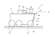
図1に示すように、水陸両用車1は、車両本体11の下部に装輪(または装軌)12を備えており、この装輪12を図示しない駆動源によって駆動することにより、陸上を走行することができるようになっている。また、水陸両用車1は、図示しないプロペラを備えており、このプロペラを図示しない駆動源によって駆動することにより、水上を航行することができるようになっている(図2参照)。つまり、水陸両用車1は、水上および陸上における移動が可能なものである。 As shown in FIG. 1, the amphibious vehicle 1 is provided with a wheeled vehicle (or tracked vehicle) 12 at the lower part of the vehicle body 11, and travels on land by driving the wheeled vehicle 12 with a drive source (not shown). You can do it. Further, the amphibious vehicle 1 is provided with a propeller (not shown), and by driving this propeller with a drive source (not shown), it is possible to navigate on the water (see FIG. 2). That is, the amphibious vehicle 1 is capable of moving on water and on land.

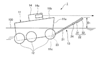
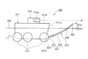
図2に示すように、水陸両用車1には、水上航行時において水から揚力を受け易くするためのフラップ(板状部材)13が車両本体11の進行方向前方側(図2においては、右方側)に設けられている。よって、水陸両用車1は、水上航行時においてフラップ13によって水から揚力を受けることにより、その航行状態を喫水の深い浮航状態から喫水の浅い滑走状態へと移行させて水上を航行することができる。 As shown in FIG. 2, in the amphibious vehicle 1, a flap (plate-shaped member) 13 for facilitating lift from water during water navigation is provided on the front side of the vehicle body 11 in the traveling direction (right in FIG. 2). It is provided on the side). Therefore, the amphibious vehicle 1 receives lift from the water by the flap 13 when sailing on the water, so that the navigation state is changed from the deep floating state of the draft to the sliding state of the shallow draft and sails on the water. can.

図1および図2に示すように、フラップ13は、車両本体11に対して展開および収納可能なもの(収納式フラップ)であり、車両本体11の前面11aに近接する(接する)ように収納される下段フラップ21と、車両本体11の上面11bに近接する(接する)ように収納される上段フラップ22とから概略構成されている。 As shown in FIGS. 1 and 2, the flap 13 is expandable and retractable with respect to the vehicle body 11 (retractable flap), and is stored so as to be close to (contact) with the front surface 11a of the vehicle body 11. It is roughly composed of a lower flap 21 and an upper flap 22 that are housed so as to be close to (contact) with the upper surface 11b of the vehicle body 11.

図1、図2および図4に示すように、下段フラップ21は、略T字形状の板状部材であり、その幅の狭い下端縁21aがヒンジ23を介して車両本体11の進行方向前方側における下端縁11cと接続されて成る。また、下段フラップ21は、当該下段フラップ21を車両本体11に対して回転動作するための第一のフラップ駆動装置41(図5参照)と機械的に接続されており、車両本体11に対して車両幅方向に延在する回転軸C1周りに回転されるようになっている。 As shown in FIGS. 1, 2 and 4, the lower flap 21 is a substantially T-shaped plate-shaped member, and its narrow lower end edge 21a is on the front side of the vehicle body 11 in the traveling direction via the hinge 23. It is connected to the lower end edge 11c of the above. Further, the lower flap 21 is mechanically connected to the first flap drive device 41 (see FIG. 5) for rotating the lower flap 21 with respect to the vehicle body 11, and is connected to the vehicle body 11. It is designed to rotate around a rotation axis C 1 extending in the vehicle width direction.

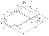
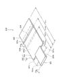
図4に示すように、上段フラップ22は、互いに摺動可能な第一の上段フラップ31と第二の上段フラップ32とから概略構成されており、第一上段フラップ31と第二上段フラップ32との摺動動作により、そのフラップ長さ(車両幅方向と直交して当該フラップ(上段フラップ22)が延在する方向における長さ)が可変に構成されている。 As shown in FIG. 4, the upper flap 22 is roughly composed of a first upper flap 31 and a second upper flap 32 that are slidable with each other, and includes the first upper flap 31 and the second upper flap 32. The flap length (the length in the direction in which the flap (upper flap 22) extends perpendicular to the vehicle width direction) is variably configured by the sliding operation of the above.

第一上段フラップ31は、略長方形状の板状部材であり、その下端縁31aがヒンジ24を介して下段フラップ21における幅の広い上端縁21bと接続されて成る。また、第一上段フラップ31は、当該第一上段フラップ31を下段フラップ21に対して回転動作するための第二のフラップ駆動装置42(図5参照)と機械的に接続されており、下段フラップ21に対して車両幅方向に延在する回転軸C2周りに回転されるようになっている。 The first upper flap 31 is a substantially rectangular plate-shaped member, and its lower end edge 31a is connected to the wide upper end edge 21b of the lower flap 21 via a hinge 24. Further, the first upper flap 31 is mechanically connected to a second flap driving device 42 (see FIG. 5) for rotating the first upper flap 31 with respect to the lower flap 21. It is designed to be rotated around a rotation axis C 2 extending in the vehicle width direction with respect to 21.

第二上段フラップ32は、略長方形状の板状部材であり、その後面32aが第一上段フラップ31の前面31bと接して第一上段フラップ31に対して摺動可能に接続されて成る。また、第二上段フラップ32は、第二上段フラップ32を第一上段フラップ31に対して摺動動作するための第三のフラップ駆動装置43(図5参照)と機械的に接続されており、第一上段フラップ31に対してV1軸方向(車両幅方向と直交して上段フラップ22(第一上段フラップ31および第二上段フラップ32)が延在する方向)に摺動されるようになっている。 The second upper flap 32 is a substantially rectangular plate-shaped member, and its rear surface 32a is in contact with the front surface 31b of the first upper flap 31 and is slidably connected to the first upper flap 31. Further, the second upper flap 32 is mechanically connected to a third flap driving device 43 (see FIG. 5) for sliding the second upper flap 32 with respect to the first upper flap 31. It is now slid with respect to the first upper flap 31 in the V1 axis direction (the direction in which the upper flap 22 (the first upper flap 31 and the second upper flap 32) extends orthogonally to the vehicle width direction). There is.

よって、上段フラップ22は、第二上段フラップ32が第一上段フラップ31に対して重なり合うように収納された短尺状態(図5においては、二点鎖線で示す状態)において、従来のものと略同等のフラップ長さL22Aを有し、第二上段フラップ32が第一上段フラップ31に対してずれるように展開された長尺状態(図5においては、実線で示す状態)において、従来のものよりも長いフラップ長さL22Bを有する。 Therefore, the upper flap 22 is substantially equivalent to the conventional one in a short state in which the second upper flap 32 is housed so as to overlap the first upper flap 31 (in the state shown by the alternate long and short dash line in FIG. 5). In a long state (a state shown by a solid line in FIG. 5), which has a flap length L 22A and is developed so that the second upper flap 32 is displaced with respect to the first upper flap 31, the conventional one. Also has a long flap length L 22B .

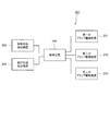
図5に示すように、水陸両用車1には、フラップ13の動作(展開および収納)を制御するための制御装置44が設けられている。制御装置44は、第一のフラップ駆動装置41、第二のフラップ駆動装置42および第三のフラップ駆動装置43とそれぞれ電気的に接続されており、これら第一のフラップ駆動装置41、第二のフラップ駆動装置42および第三のフラップ駆動装置43の駆動をそれぞれ独立して制御することができるようになっている。 As shown in FIG. 5, the amphibious vehicle 1 is provided with a control device 44 for controlling the operation (deployment and storage) of the flap 13. The control device 44 is electrically connected to the first flap drive device 41, the second flap drive device 42, and the third flap drive device 43, respectively, and these first flap drive device 41 and the second flap drive device 41, respectively. The drive of the flap drive device 42 and the third flap drive device 43 can be controlled independently.

ここで、第一のフラップ駆動装置41、第二のフラップ駆動装置42および第三のフラップ駆動装置43としては、種々の駆動源および機構等をそれぞれ採用することができる。例えば、駆動源としての油圧シリンダ(伸縮部材)を部材間(車両本体11と下段フラップ21との間、下段フラップ21と第一上段フラップ31との間、第一上段フラップ31と第二上段フラップ32との間)に設けることにより、油圧シリンダの伸縮動作を利用して部材間の回転動作および摺動動作を行うことができる。また、例えば、駆動源としてのモータ(動力発生機)およびギヤ機構(またはワイヤ機構)を部材間(車両本体11と下段フラップ21との間、下段フラップ21と第一上段フラップ31との間、第一上段フラップ31と第二上段フラップ32との間)に設けることにより、モータの回転動作を利用して部材間の回転動作および摺動動作を行うことができる。 Here, various drive sources, mechanisms, and the like can be adopted as the first flap drive device 41, the second flap drive device 42, and the third flap drive device 43, respectively. For example, a hydraulic cylinder (expandable member) as a drive source can be inserted between members (between the vehicle body 11 and the lower flap 21, between the lower flap 21 and the first upper flap 31, and between the first upper flap 31 and the second upper flap 31. By providing it (between 32), it is possible to perform a rotational operation and a sliding operation between the members by utilizing the expansion and contraction operation of the hydraulic cylinder. Further, for example, a motor (power generator) and a gear mechanism (or a wire mechanism) as drive sources are placed between members (between the vehicle body 11 and the lower flap 21 and between the lower flap 21 and the first upper flap 31. By providing it between the first upper flap 31 and the second upper flap 32), it is possible to perform a rotational operation and a sliding operation between the members by utilizing the rotational operation of the motor.

また、図5に示すように、水陸両用車1には、当該水陸両用車1の移動状態(水上航行または陸上走行等)を検出可能な移動状態検出装置45と、水上航行時における水陸両用車1の航行状態を検出可能な航行状態検出装置46とが設けられている。移動状態検出手段45および航行状態検出装置46は、制御装置44とそれぞれ電気的に接続されており、制御装置44は、移動状態検出45および航行状態検出装置46の検出結果に基づいて、第一のフラップ駆動装置41、第二のフラップ駆動装置42および第三のフラップ駆動装置43の駆動をそれぞれ制御するようになっている。 Further, as shown in FIG. 5, the amphibious vehicle 1 includes a moving state detection device 45 capable of detecting the moving state (water navigation, land traveling, etc.) of the amphibious vehicle 1 and an amphibious vehicle during water navigation. A navigation state detection device 46 capable of detecting the navigation state of 1 is provided. The moving state detecting means 45 and the navigation state detecting device 46 are electrically connected to the control device 44, respectively, and the control device 44 is the first based on the detection results of the moving state detecting 45 and the navigation state detecting device 46. The flap drive device 41, the second flap drive device 42, and the third flap drive device 43 are controlled respectively.

ここで、移動状態検出装置45および航行状態検出装置46としては、種々のセンサ等を採用することができる。例えば、移動状態検出装置45としては、乗員が操作するスイッチや水陸両用車1が進水したことを検出する水圧センサ等を採用することができ、航行状態検出装置46としては、水上航行における移動速度を検出する速度センサ等を採用することができる。なお、航行状態検出装置46として速度センサを採用した場合には、制御装置44は、水陸両用車1の水上航行時における移動速度が所定値未満である場合には、水陸両用車1が浮航状態であると判断し、水陸両用車1の水上航行時における移動速度が所定値以上である場合には、水陸両用車1が滑走状態であると判断する。 Here, various sensors and the like can be adopted as the moving state detecting device 45 and the navigation state detecting device 46. For example, as the movement state detection device 45, a switch operated by an occupant, a water pressure sensor for detecting that the amphibious vehicle 1 has been launched, or the like can be adopted, and as the navigation state detection device 46, movement in water navigation can be adopted. A speed sensor or the like that detects the speed can be adopted. When a speed sensor is adopted as the navigation state detection device 46, the control device 44 causes the amphibious vehicle 1 to float when the moving speed of the amphibious vehicle 1 during water navigation is less than a predetermined value. If it is determined that the amphibious vehicle 1 is in a state and the moving speed of the amphibious vehicle 1 during water navigation is equal to or higher than a predetermined value, it is determined that the amphibious vehicle 1 is in a gliding state.

本発明の実施例1に係る水陸両用車の動作について、図1から図5を参照して説明する。 The operation of the amphibious vehicle according to the first embodiment of the present invention will be described with reference to FIGS. 1 to 5.

まず、水陸両用車1が図示しない動力源によって装輪12を駆動して陸上を走行しているとき、フラップ13は全収納状態にある(図1参照)。 First, when the amphibious vehicle 1 drives the wheeled vehicle 12 by a power source (not shown) and travels on land, the flap 13 is in a fully retracted state (see FIG. 1).

全収納状態のフラップ13は、下段フラップ21が車両本体11の前面11aに近接するように収納されると共に、上段フラップ22が短尺状態で車両本体11の上面11bに近接するように収納された状態である。 The flap 13 in the fully stored state is a state in which the lower flap 21 is stored so as to be close to the front surface 11a of the vehicle body 11, and the upper flap 22 is stored so as to be close to the upper surface 11b of the vehicle body 11 in a short state. Is.

続いて、例えば、水陸両用車1が進水して図示しない動力源によって図示しないプロペラを駆動して水上を航行すると、移動状態検出装置45は、水陸両用車1の移動状態が陸上走行状態から水上航行状態へと移行したことを検出する(図2および図5参照)。 Subsequently, for example, when the amphibious vehicle 1 is launched and a propeller (not shown) is driven by a power source (not shown) to navigate on the water, the moving state detection device 45 changes the moving state of the amphibious vehicle 1 from the land traveling state. Detects the transition to the water navigation state (see FIGS. 2 and 5).

また、水陸両用車1が陸上走行状態から水上航行状態へと移行した直後は、当該水陸両用車1は喫水の深い浮航状態であるので、航行状態検出装置46は、水陸両用車1の航行状態が浮航状態であることを検出する。 Immediately after the amphibious vehicle 1 shifts from the land traveling state to the water navigation state, the amphibious vehicle 1 is in a deep draft state, so that the navigation state detection device 46 is used to navigate the amphibious vehicle 1. Detects that the state is a floating state.

よって、制御装置44は、これら移動状態検出装置45および航行状態検出装置46の検出結果に基づいて、第一のフラップ駆動装置41と第二のフラップ駆動装置42と第三のフラップ駆動装置43とをそれぞれ駆動し、フラップ13を全収納状態から全展開状態へ変態する。 Therefore, the control device 44 includes the first flap drive device 41, the second flap drive device 42, and the third flap drive device 43 based on the detection results of the movement state detection device 45 and the navigation state detection device 46. , And transform the flap 13 from the fully retracted state to the fully deployed state.

全展開状態のフラップ13は、下段フラップ21が車両本体11の前面11aから離れるように展開されると共に、上段フラップ22が長尺状態で車両本体11の上面11bから離れるように展開された状態である。 The flap 13 in the fully deployed state is in a state in which the lower flap 21 is deployed so as to be separated from the front surface 11a of the vehicle body 11, and the upper flap 22 is deployed so as to be separated from the upper surface 11b of the vehicle body 11 in a long state. be.

つまり、水陸両用車1が陸上走行状態から水上航行状態(浮航状態)へ移行すると、下段フラップ21が第一のフラップ駆動装置41によって車両本体11の前面11aから離れるように展開されると共に、第一上段フラップ31が第二のフラップ駆動装置42によって車両本体11の上面11bから離れるように展開され、第二上段フラップ32が第三のフラップ駆動装置43によって第一上段フラップ31に対してずれるように展開される。 That is, when the amphibious vehicle 1 shifts from the land traveling state to the water navigation state (floating state), the lower flap 21 is deployed by the first flap driving device 41 so as to be separated from the front surface 11a of the vehicle body 11. The first upper flap 31 is deployed by the second flap drive device 42 so as to be separated from the upper surface 11b of the vehicle body 11, and the second upper flap 32 is displaced from the first upper flap 31 by the third flap drive device 43. It is expanded like this.

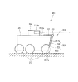
続いて、水陸両用車1が水上航行において増速して浮航状態から滑走状態へ移行すると、航行状態検出装置46は、水陸両用車1の航行状態が浮航状態から滑走状態へと移行したことを検出する(図3および図5参照)。 Subsequently, when the amphibious vehicle 1 speeds up in water navigation and shifts from the floating state to the sliding state, the navigation state detection device 46 shifts the navigation state of the amphibious vehicle 1 from the floating state to the sliding state. (See FIGS. 3 and 5).

よって、制御装置44は、この航行状態検出装置46の検出結果に基づいて、第三のフラップ駆動装置43だけを駆動し、フラップ13を全展開状態から部分展開状態(部分収納状態)へ変態する。 Therefore, the control device 44 drives only the third flap drive device 43 based on the detection result of the navigation state detection device 46, and transforms the flap 13 from the fully expanded state to the partially expanded state (partially retracted state). ..

部分展開状態(部分収納状態)のフラップ13は、下段フラップ21が車両本体11の前面11aから離れるように展開されると共に、上段フラップ22が短尺状態で車両本体11の上面11bから離れるように展開された状態である。 The flap 13 in the partially expanded state (partially stored state) is deployed so that the lower flap 21 is separated from the front surface 11a of the vehicle body 11 and the upper flap 22 is deployed so as to be separated from the upper surface 11b of the vehicle body 11 in a short state. It is in a state of being done.

つまり、水陸両用車1が水上航行状態において浮航状態から滑走状態へ移行すると、下段フラップ21および第一上段フラップ31が展開されたままの状態で、第二上段フラップ32が第三のフラップ駆動装置43によって第一上段フラップ31に対して重なり合うように収納される。 That is, when the amphibious vehicle 1 shifts from the floating state to the sliding state in the water navigation state, the second upper flap 32 drives the third flap while the lower flap 21 and the first upper flap 31 remain deployed. It is stored by the device 43 so as to overlap with the first upper flap 31.

続いて、水陸両用車1が水上航行において減速して滑走状態から浮航状態へと移行すると、航行状態検出装置46は、水陸両用車1の航行状態が滑走状態から浮航状態へと移行したことを検出する(図2および図5参照)。 Subsequently, when the amphibious vehicle 1 decelerates in water navigation and shifts from the sliding state to the floating state, the navigation state detection device 46 shifts the navigation state of the amphibious vehicle 1 from the sliding state to the floating state. (See FIGS. 2 and 5).

よって、制御装置44は、この航行状態検出装置46の検出結果に基づいて、第三のフラップ駆動装置43だけを駆動し、フラップ13を部分展開状態(部分収納状態)から全展開状態へ変態する。 Therefore, the control device 44 drives only the third flap drive device 43 based on the detection result of the navigation state detection device 46, and transforms the flap 13 from the partially expanded state (partially retracted state) to the fully expanded state. ..

つまり、水陸両用車1が水上航行状態において滑走状態から浮航状態へ移行すると、下段フラップ21および第一上段フラップ31が展開されたままの状態で、第二上段フラップ32が第三のフラップ駆動装置43によって第一上段フラップ31に対してずれるように展開される。 That is, when the amphibious vehicle 1 shifts from the gliding state to the floating state in the water navigation state, the second upper flap 32 drives the third flap while the lower flap 21 and the first upper flap 31 remain deployed. It is deployed by the device 43 so as to be displaced with respect to the first upper flap 31.

続いて、例えば、水陸両用車1が上陸して図示しない動力源によって装輪12を駆動して陸上を走行すると、移動状態検出装置45は、水陸両用車1の移動状態が水上航行状態から陸上走行状態へと移行したことを検出する(図1および図5参照)。 Subsequently, for example, when the amphibious vehicle 1 lands and drives the wheeled vehicle 12 by a power source (not shown) to travel on land, the movement state detection device 45 changes the moving state of the amphibious vehicle 1 from the water navigation state to land. It detects that the vehicle has entered the running state (see FIGS. 1 and 5).

よって、制御装置44は、この移動状態検出装置45の検出結果に基づいて、第一のフラップ駆動装置41と第二のフラップ駆動装置42と第三のフラップ駆動装置43とをそれぞれ駆動し、フラップ13を全展開状態から全収納状態へ変態する。 Therefore, the control device 44 drives the first flap drive device 41, the second flap drive device 42, and the third flap drive device 43, respectively, based on the detection result of the movement state detection device 45, and flaps. 13 is transformed from the fully deployed state to the fully stored state.

つまり、水陸両用車1が水上航行状態(浮航状態)から陸上走行状態へ移行すると、第二上段フラップ32が第三のフラップ駆動装置43によって第一上段フラップ31に対して重なり合うように収納され、下段フラップ21が第一のフラップ駆動装置41によって車両本体11の前面11aに近接するように収納されると共に、第一上段フラップ31(上段フラップ22)が第二のフラップ駆動装置42によって車両本体11の上面11bに近接するように収納される。 That is, when the amphibious vehicle 1 shifts from the water navigation state (floating state) to the land traveling state, the second upper flap 32 is stored by the third flap drive device 43 so as to overlap the first upper flap 31. The lower flap 21 is housed by the first flap drive device 41 so as to be close to the front surface 11a of the vehicle body 11, and the first upper flap 31 (upper flap 22) is housed by the second flap drive device 42. It is stored so as to be close to the upper surface 11b of 11.

本実施例に係る水陸両用車1によれば、上段フラップ22(フラップ13)がそのフラップ長さを可変に構成されているので、長尺状態の上段フラップ22のフラップ長さL22Bを従来のものよりも長く設定し、全展開状態のフラップ13のフラップ長さL13を従来のものよりも長く設定することができる(図4参照)。このように従来のものよりも長大なフラップ13を備えることにより、水陸両用車1は、水上航行時において従来のものよりも水からの揚力を受け易くなるので、従来のものよりも効率的に浮航状態から滑走状態へと移行して目的地まで早く移動することができる。 According to the amphibious vehicle 1 according to the present embodiment, since the upper flap 22 (flap 13) is configured to have a variable flap length, the flap length L 22B of the upper flap 22 in the long state can be changed to the conventional one. The flap length L 13 of the flap 13 in the fully unfolded state can be set longer than that of the conventional one (see FIG. 4). By providing the flap 13 which is longer than the conventional one in this way, the amphibious vehicle 1 is more likely to receive lift from water than the conventional one when sailing on the water, and thus is more efficient than the conventional one. It is possible to move quickly to the destination by shifting from the floating state to the gliding state.

また、本実施例に係る水陸両用車1によれば、長大なフラップ13を備えているので、フラップ13と水面(喫水線)100との接触角度θ1を従来のものよりも小さく設定することができる(図2参照)。このようにフラップ13と水面(喫水線)100との接触角度θ1を小さく設定することにより、水陸両用車1は、水上航行時において従来のものよりも水の抵抗をより低減して航行することができるので、従来のものよりもより効率的に浮航状態から滑走状態へ移行して目的地までより早く移動することができる。 Further, according to the amphibious vehicle 1 according to the present embodiment, since the long flap 13 is provided, the contact angle θ 1 between the flap 13 and the water surface (waterline) 100 can be set smaller than that of the conventional one. Yes (see Figure 2). By setting the contact angle θ 1 between the flap 13 and the water surface (waterline) 100 to be small in this way, the amphibious vehicle 1 can sail with less water resistance than the conventional one when sailing on the water. Therefore, it is possible to move from the floating state to the gliding state more efficiently than the conventional one and move to the destination faster.

また、本実施例に係る水陸両用車1によれば、上段フラップ22がそのフラップ長さを可変に構成されているので、短尺状態の上段フラップ22のフラップ長さL22Aを従来のものと略同等の長さに設定することができる(図1および図4参照)。このように短尺状態の上段フラップ22を従来のものと略同等のフラップ長さL22Aとすることにより、車両本体11の上面11bから突出して設けられる運転席14等と干渉させることなく、かつ、運転席14の車窓14aからの視界を妨げることなく、上段フラップ22(第一上段フラップ31および第二上段フラップ32)を車両本体11の上面11bに近接するように収納することができる。 Further, according to the amphibious vehicle 1 according to the present embodiment, since the upper flap 22 has a variable flap length, the flap length L 22A of the upper flap 22 in a short state is abbreviated as that of the conventional one. It can be set to the same length (see FIGS. 1 and 4). By setting the upper flap 22 in the short state to have a flap length L 22A substantially equal to that of the conventional one, the upper flap 22 does not interfere with the driver's seat 14 or the like protruding from the upper surface 11b of the vehicle body 11 and is not interfered with. The upper flaps 22 (first upper flap 31 and second upper flap 32) can be stored close to the upper surface 11b of the vehicle body 11 without obstructing the view from the vehicle window 14a of the driver's seat 14.

また、本実施例に係る水陸両用車1によれば、短尺状態の上段フラップ22(第一上段フラップ31および第二上段フラップ32)を車両本体11の上面11bに近接するように収納することができるので、下段フラップ21を車両本体11の前面11aに近接するように収納することができる(図1参照)。このように下段フラップ21を車両本体11の前面11aに近接するように収納することにより、水陸両用車1は、陸上走行時においてフラップ13(下段フラップ21)を段差等と接触させることなく、陸上(不整地や段差等)を走行することができる。 Further, according to the amphibious vehicle 1 according to the present embodiment, the short upper flaps 22 (first upper flap 31 and second upper flap 32) can be stored so as to be close to the upper surface 11b of the vehicle body 11. Therefore, the lower flap 21 can be stored so as to be close to the front surface 11a of the vehicle body 11 (see FIG. 1). By storing the lower flap 21 so as to be close to the front surface 11a of the vehicle body 11 in this way, the amphibious vehicle 1 does not bring the flap 13 (lower flap 21) into contact with a step or the like during land traveling, and land. Can drive on rough terrain, steps, etc.

また、本実施例に係る水陸両用車1によれば、上段フラップ22(フラップ13)がそのフラップ長さを可変に構成されているので、水陸両用車1の航行状態が滑走状態に移行した際には、上段フラップ22(フラップ13)を短尺状態とすることにより、フラップ13の水面(喫水線)100から突出する突出量D1を抑えることができる(図3参照)。このように滑走状態においてフラップ13の水面100からの突出量D1を抑えることにより、水陸両用車1は、水上航行時において空気の抵抗を低減して航行することができるので、滑走状態で効率的に航行して目的地まで早く移動することができる。 Further, according to the amphibious vehicle 1 according to the present embodiment, since the upper flap 22 (flap 13) has a variable flap length, when the navigation state of the amphibious vehicle 1 shifts to the gliding state. By setting the upper flap 22 (flap 13) to a short state, it is possible to suppress the amount of protrusion D 1 protruding from the water surface (waterline) 100 of the flap 13 (see FIG. 3). By suppressing the amount of protrusion D 1 of the flap 13 from the water surface 100 in the sliding state in this way, the amphibious vehicle 1 can sail with reduced air resistance during water navigation, and thus is efficient in the sliding state. You can navigate to your destination quickly.

また、本実施例に係る水陸両用車1によれば、滑走状態において車両本体11の前方部が上向き(鉛直方向上側)に傾いたとしても、フラップ13の水面100からの突出量D1を抑えることにより、運転席14の車窓14aから水平方向における視界を良好に確保することができる(図3参照)。 Further, according to the amphibious vehicle 1 according to the present embodiment, even if the front portion of the vehicle body 11 tilts upward (upper in the vertical direction) in the sliding state, the amount D 1 of the flap 13 protruding from the water surface 100 is suppressed. As a result, it is possible to secure a good view in the horizontal direction from the vehicle window 14a of the driver's seat 14 (see FIG. 3).

本実施例においては、上段フラップ22を互いに摺動可能な第一上段フラップ31と第二上段フラップ32とから概略構成し、これら第一上段フラップ31と第二上段フラップ32との摺動動作により、上段フラップ22(フラップ13)のフラップ長さを可変に構成している。もちろん、本発明は、本実施例の構成のものに限定されない。 In this embodiment, the upper flap 22 is roughly configured from a first upper flap 31 and a second upper flap 32 that can slide with each other, and by the sliding operation of the first upper flap 31 and the second upper flap 32. , The flap length of the upper flap 22 (flap 13) is variably configured. Of course, the present invention is not limited to the configuration of the present embodiment.

例えば、図6に示すように、上段フラップ122を互いに回転可能な第一上段フラップ131と第二上段フラップ132とから概略構成し、これら第一上段フラップ131と第二上段フラップ132との回転動作(第一上段フラップ131に対して第二上段フラップ132を折り畳むように回転すること)により、上段フラップ122(フラップ113)のフラップ長さを可変に構成しても良い。このような構成の収納式フラップ113は、図示しない水陸両用車の車両本体とヒンジ123を介して回転軸C101周りに回転可能に接続される下段フラップ121と、この下段フラップ121とヒンジ124を介して回転軸C102周りに回転可能に接続される第一上段フラップ131と、この第一上段フラップ131とヒンジ125を介して回転軸C103周りに回転可能に接続される第二上段フラップ132とを備える。なお、上述した構成の収納式フラップ113を備えた水陸両用車は、実施例1に係る水陸両用車1と同様の作用効果を奏することは言うまでもない。 For example, as shown in FIG. 6, the upper flap 122 is roughly configured from the first upper flap 131 and the second upper flap 132 that can rotate with each other, and the rotational operation of the first upper flap 131 and the second upper flap 132. The flap length of the upper flap 122 (flap 113) may be variably configured by (rotating the second upper flap 132 so as to fold with respect to the first upper flap 131). The retractable flap 113 having such a configuration includes a lower flap 121 rotatably connected around the rotation shaft C 101 via a hinge 123 to the vehicle body of an amphibious vehicle (not shown), and the lower flap 121 and the hinge 124. The first upper flap 131 rotatably connected around the rotary shaft C 102 via the hinge 125, and the second upper flap 132 rotatably connected around the rotary shaft C 103 via the first upper flap 131 and the hinge 125. And. Needless to say, the amphibious vehicle provided with the retractable flap 113 having the above-described configuration has the same effect as that of the amphibious vehicle 1 according to the first embodiment.

また、本実施例においては、下段フラップ21(下段フラップ121)と装輪12との干渉を回避するために、下段フラップ21を略T字形状に形成して当該下段フラップ21に切り欠き部21c(切り欠き部121c)を設けている。もちろん、本発明は、本実施例の構成のものに限定されない。例えば、装輪との干渉を回避する程度に下段フラップを矩形形状に近い形状で形成しても良く、また、略T字形状に形成した下段フラップの切り欠き部を水上航行時において閉塞可能な構成としても良い。 Further, in the present embodiment, in order to avoid interference between the lower flap 21 (lower flap 121) and the wheeled wheel 12, the lower flap 21 is formed in a substantially T shape and the notch portion 21c is formed in the lower flap 21. (Cutout portion 121c) is provided. Of course, the present invention is not limited to the configuration of the present embodiment. For example, the lower flap may be formed in a shape close to a rectangular shape to the extent that interference with the wheel is avoided, and the notch portion of the lower flap formed in a substantially T shape can be closed during water navigation. It may be configured.

また、本実施例においては、水陸両用車1の移動状態が水上航行状態または陸上走行状態へ移行すると、移動状態検出装置45がその移行状態を検出し、制御装置44がその移動状態検出装置45の検出結果に基づいて第一のフラップ駆動装置41、第二のフラップ駆動装置42および第三のフラップ駆動装置43の駆動をそれぞれ制御するようにしている。もちろん、本発明は、本実施例の動作のものに限定されない。例えば、制御装置が移動状態検出装置であるスイッチの操作に基づいて第一のフラップ駆動装置、第二のフラップ駆動装置および第三のフラップ駆動装置の駆動をそれぞれ制御するようにしても良く、また、移動状態検出装置を水陸両用車の移動状態の移行を予測することができるものとし、制御装置が水陸両用車の移動状態の移行前(直前)に第一のフラップ駆動装置、第二のフラップ駆動装置および第三のフラップ駆動装置の駆動をそれぞれ制御するようにしても良い。これらの動作によれば、例えば、水陸両用車が水上に浮いた状態においてフラップを収納することも可能である。 Further, in the present embodiment, when the moving state of the amphibious vehicle 1 shifts to the water navigation state or the land traveling state, the moving state detection device 45 detects the transition state, and the control device 44 detects the moving state detection device 45. The drive of the first flap drive device 41, the second flap drive device 42, and the third flap drive device 43 is controlled based on the detection result of the above. Of course, the present invention is not limited to the operation of the present embodiment. For example, the control device may control the drive of the first flap drive device, the second flap drive device, and the third flap drive device, respectively, based on the operation of the switch which is the movement state detection device. , The movement state detection device shall be able to predict the transition of the movement state of the amphibious vehicle, and the control device shall be the first flap drive device and the second flap before (immediately before) the transition of the movement state of the amphibious vehicle. The drive of the drive device and the drive of the third flap drive device may be controlled respectively. According to these operations, for example, it is possible to store the flap while the amphibious vehicle is floating on the water.

[実施例2]
本発明の実施例2に係る水陸両用車の構造について、図7から図11を参照して説明する。
[Example 2]
The structure of the amphibious vehicle according to the second embodiment of the present invention will be described with reference to FIGS. 7 to 11.

本実施例に係る水陸両用車は、フラップの構成を除いて、本発明の実施例1に係る水陸両用車と同様な構造を有するものである。よって、本実施例に係る水陸両用車における実施例1と同様な構造についての重複説明は適宜省略する。 The amphibious vehicle according to the present embodiment has the same structure as the amphibious vehicle according to the first embodiment of the present invention except for the flap configuration. Therefore, the duplicate description of the structure similar to that of the first embodiment in the amphibious vehicle according to the present embodiment will be omitted as appropriate.

図7および図8に示すように、水陸両用車201には、水上航行時において水から揚力を受け易くするためのフラップ(板状部材)213が設けられている。フラップ213は、車両本体211に対して展開および収納可能なもの(収納式フラップ)であり、車両本体211の前面211aに近接する(接する)ように収納される下段フラップ221と、車両本体211の上面211bに近接する(接する)ように収納される上段フラップ222とから概略構成されている。 As shown in FIGS. 7 and 8, the amphibious vehicle 201 is provided with a flap (plate-shaped member) 213 for easily receiving lift from water during water navigation. The flap 213 is a retractable flap that can be deployed and stored with respect to the vehicle body 211, and is a lower flap 221 that is stored so as to be close to (contact) with the front surface 211a of the vehicle body 211, and the vehicle body 211. It is roughly configured from an upper flap 222 that is housed so as to be close to (contact) with the upper surface 211b.

図7、図8および図10に示すように、下段フラップ221は、互いに摺動可能な第一下段フラップ231と第二下段フラップ232とから概略構成されており、第一下段フラップ231と第二下段フラップ232との摺動動作により、そのフラップ長さ(車両幅方向と直交して当該フラップ(下段フラップ221)が延在する方向における長さ)が可変に構成されている。 As shown in FIGS. 7, 8 and 10, the lower flap 221 is roughly composed of a first lower flap 231 and a second lower flap 232 that are slidable with each other, and the lower flap 231 and the first lower flap 231. By sliding with the second lower flap 232, the flap length (the length in the direction in which the flap (lower flap 221) extends perpendicular to the vehicle width direction) is variably configured.

第一下段フラップ231は、幅の狭い略長方形状の板状部材であり、その下端縁231aがヒンジ223を介して車両本体211の進行方向前方側における下端縁211cと接続されて成る。また、第一下段フラップ231は、当該第一下段フラップ231を車両本体211に対して回転動作するための第一のフラップ駆動装置241(図11参照)と機械的に接続されており、車両本体211に対して車両幅方向に延在する回転軸C201周りに回転されるようになっている。 The first lower flap 231 is a substantially rectangular plate-shaped member having a narrow width, and its lower end edge 231a is connected to the lower end edge 211c on the front side in the traveling direction of the vehicle body 211 via a hinge 223. Further, the first lower flap 231 is mechanically connected to the first flap drive device 241 (see FIG. 11) for rotating the first lower flap 231 with respect to the vehicle body 211. It is rotated around a rotation axis C 201 extending in the vehicle width direction with respect to the vehicle body 211.

第二下段フラップ232は、幅の広い略長方形状の板状部材であり、その後面232aが第一下段フラップ231の前面231bと接して第一下段フラップ231に対して摺動可能に接続されて成る。また、第二下段フラップ232は、第二下段フラップ232を第一下段フラップ231に対して摺動動作するための第二のフラップ駆動装置242(図11参照)と機械的に接続されており、第一下段フラップ231に対してV201軸方向(車両幅方向と直交して下段フラップ221(第一下段フラップ231および第二下段フラップ232)が延在する方向)に摺動されるようになっている。 The second lower flap 232 is a wide, substantially rectangular plate-shaped member, and its rear surface 232a is in contact with the front surface 231b of the first lower flap 231 and is slidably connected to the first lower flap 231. It is made up of. Further, the second lower flap 232 is mechanically connected to a second flap driving device 242 (see FIG. 11) for sliding the second lower flap 232 with respect to the first lower flap 231. , Sliding in the V201 axis direction (the direction in which the lower flap 221 (first lower flap 231 and second lower flap 232) extends orthogonally to the vehicle width direction) with respect to the first lower flap 231. It has become.

よって、下段フラップ221は、第二下段フラップ232が第一下段フラップ231に対して重なり合うように収納された短尺状態(図10においては、二点鎖線で示す状態)において、従来のものと略同等のフラップ長さL221Aを有し、第二下段フラップ232が第一下段フラップ231に対してずれるように展開された長尺状態(図10においては、実線で示す状態)において、従来のものよりも長いフラップ長さL221Bを有する。 Therefore, the lower flap 221 is abbreviated as the conventional one in a short state (in the state shown by the alternate long and short dash line in FIG. 10) in which the second lower flap 232 is housed so as to overlap the first lower flap 231. In a long state (shown by a solid line in FIG. 10), which has an equivalent flap length L 221A and is developed so that the second lower flap 232 is displaced with respect to the first lower flap 231. It has a longer flap length L 221B than the one.

図10に示すように、上段フラップ222は、略長方形状の板状部材であり、その下端縁222aがヒンジ224を介して第二下段フラップ232の上端縁232bと接続されて成る。また、上段フラップ222は、当該上段フラップ222を第二下段フラップ232に対して回転動作するための第三のフラップ駆動装置243(図11参照)と機械的に接続されており、下段フラップ221(第二下段フラップ231)に対して車両幅方向に延在する回転軸C202周りに回転されるようになっている。 As shown in FIG. 10, the upper flap 222 is a substantially rectangular plate-shaped member, and its lower end edge 222a is connected to the upper end edge 232b of the second lower flap 232 via a hinge 224. Further, the upper flap 222 is mechanically connected to a third flap driving device 243 (see FIG. 11) for rotating the upper flap 222 with respect to the second lower flap 232, and the lower flap 221 (see FIG. 11) is mechanically connected. The second lower flap 231) is rotated around a rotation axis C 202 extending in the vehicle width direction.

図11に示すように、水陸両用車201には、フラップ213の動作(展開および収納)を制御するための制御装置244が設けられている。制御装置244は、第一のフラップ駆動装置241、第二のフラップ駆動装置242および第三のフラップ駆動装置243とそれぞれ電気的に接続されており、これら第一のフラップ駆動装置241、第二のフラップ駆動装置242および第三のフラップ駆動装置243の駆動をそれぞれ独立して制御することができるようになっている。ここで、第一のフラップ駆動装置241、第二のフラップ駆動装置242および第三のフラップ駆動装置243としては、実施例1と同様に、種々の駆動源および機構等をそれぞれ採用することができる。 As shown in FIG. 11, the amphibious vehicle 201 is provided with a control device 244 for controlling the operation (deployment and storage) of the flap 213. The control device 244 is electrically connected to the first flap drive device 241 and the second flap drive device 242 and the third flap drive device 243, respectively, and the first flap drive device 241 and the second flap drive device 241 are used. The drive of the flap drive device 242 and the third flap drive device 243 can be controlled independently. Here, as the first flap drive device 241 and the second flap drive device 242 and the third flap drive device 243, various drive sources, mechanisms, and the like can be adopted as in the first embodiment. ..

また、図11に示すように、水陸両用車201には、当該水陸両用車201の移動状態(水上航行または陸上走行等)を検出可能な移動状態検出装置245と、水上航行時における水陸両用車201の航行状態を検出可能な航行状態検出装置246が設けられている。移動状態検出手段245および航行状態検出装置246は、制御装置244とそれぞれ電気的に接続されており、制御装置244は、移動状態検出245および航行状態検出装置246の検出結果に基づいて、第一のフラップ駆動装置241、第二のフラップ駆動装置242および第三のフラップ駆動装置243の駆動をそれぞれ制御するようになっている。ここで、移動状態検出装置245および航行状態検出装置246としては、実施例1と同様に、種々のセンサ等を採用することができる。 Further, as shown in FIG. 11, the amphibious vehicle 201 includes a moving state detection device 245 capable of detecting the moving state (water navigation, land traveling, etc.) of the amphibious vehicle 201, and an amphibious vehicle during water navigation. A navigation state detection device 246 capable of detecting the navigation state of 201 is provided. The moving state detection means 245 and the navigation state detection device 246 are electrically connected to the control device 244, respectively, and the control device 244 is the first based on the detection results of the movement state detection 245 and the navigation state detection device 246. The flap drive device 241, the second flap drive device 242, and the third flap drive device 243 are controlled respectively. Here, as the moving state detecting device 245 and the navigation state detecting device 246, various sensors and the like can be adopted as in the first embodiment.

本発明の実施例2に係る水陸両用車の動作について、図7から図11を参照して説明する。 The operation of the amphibious vehicle according to the second embodiment of the present invention will be described with reference to FIGS. 7 to 11.

まず、水陸両用車201が図示しない動力源によって装輪(または装軌)212を駆動して陸上を走行しているとき、フラップ213は全収納状態にある(図7参照)。 First, when the amphibious vehicle 201 is traveling on land by driving the wheeled (or tracked) 212 by a power source (not shown), the flap 213 is in the fully retracted state (see FIG. 7).

全収納状態のフラップ213は、下段フラップ221が短尺状態で車両本体211の前面211aに近接するように収納されると共に、上段フラップ222が車両本体211の上面211bに近接するように収納された状態である。 The flaps 213 in the fully stored state are stored so that the lower flap 221 is in a short state and is close to the front surface 211a of the vehicle body 211, and the upper flap 222 is stored so as to be close to the upper surface 211b of the vehicle body 211. Is.

続いて、例えば、水陸両用車201が進水して図示しない動力源によって図示しないプロペラを駆動して水上を航行すると、移動状態検出装置245は、水陸両用車201の移動状態が陸上走行状態から水上航行状態へと移行したことを検出する(図8および図11参照)。 Subsequently, for example, when the amphibious vehicle 201 is launched and a propeller (not shown) is driven by a power source (not shown) to navigate on the water, the movement state detection device 245 changes the moving state of the amphibious vehicle 201 from the land traveling state. It detects that it has transitioned to the water navigation state (see FIGS. 8 and 11).

また、水陸両用車201が陸上走行状態から水上航行状態へと移行した直後は、当該水陸両用車201は喫水の深い浮航状態であるので、航行状態検出装置246は、水陸両用車201の航行状態が浮航状態であることを検出する。 Immediately after the amphibious vehicle 201 shifts from the land traveling state to the water navigation state, the amphibious vehicle 201 is in a deep draft state, so that the navigation state detection device 246 navigates the amphibious vehicle 201. Detects that the state is a floating state.

よって、制御装置244は、これら移動状態検出装置245および航行状態検出装置246の検出結果に基づいて、第一のフラップ駆動装置241と第二のフラップ駆動装置242と第三のフラップ駆動装置243とをそれぞれ駆動し、フラップ213を全収納状態から全展開状態へ変態する。 Therefore, the control device 244 includes the first flap drive device 241 and the second flap drive device 242 and the third flap drive device 243 based on the detection results of the movement state detection device 245 and the navigation state detection device 246. , And transform the flap 213 from the fully retracted state to the fully deployed state.

全展開状態のフラップ213は、下段フラップ221が長尺状態で車両本体211の前面211aから離れるように展開されると共に、上段フラップ222が車両本体11の上面211bから離れるように展開された状態である。 The flap 213 in the fully deployed state is deployed so that the lower flap 221 is elongated and separated from the front surface 211a of the vehicle body 211, and the upper flap 222 is deployed so as to be separated from the upper surface 211b of the vehicle body 11. be.

つまり、水陸両用車201が陸上走行状態から水上航行状態(浮航状態)へ移行すると、下段フラップ221(第一下段フラップ231)が第一のフラップ駆動装置241によって車両本体211の前面211aから離れるように展開されると共に、第二下段フラップ232が第二のフラップ駆動装置242によって第一下段フラップ231に対してずれるように展開され、上段フラップ222が第三のフラップ駆動装置243によって車両本体211の上面211bから離れるように展開される。 That is, when the amphibious vehicle 201 shifts from the land traveling state to the water navigation state (floating state), the lower flap 221 (first lower flap 231) is moved from the front 211a of the vehicle body 211 by the first flap drive device 241. The second lower flap 232 is deployed so as to be separated from the first lower flap 231 by the second flap drive device 242, and the upper flap 222 is deployed by the third flap drive device 243 so as to be separated from the first lower flap 231. It is deployed so as to be separated from the upper surface 211b of the main body 211.

続いて、水陸両用車201が水上航行において増速して浮航状態から滑走状態へ移行すると、航行状態検出装置246は、水陸両用車201の航行状態が浮航状態から滑走状態へと移行したことを検出する(図9および図11参照)。 Subsequently, when the amphibious vehicle 201 speeds up in water navigation and shifts from the floating state to the sliding state, the navigation state detection device 246 shifts the navigation state of the amphibious vehicle 201 from the floating state to the sliding state. (See FIGS. 9 and 11).

よって、制御装置244は、この航行状態検出装置246の検出結果に基づいて、第二のフラップ駆動装置242だけを駆動し、フラップ213を全展開状態から部分展開状態(部分収納状態)へ変態する。 Therefore, the control device 244 drives only the second flap drive device 242 based on the detection result of the navigation state detection device 246, and transforms the flap 213 from the fully expanded state to the partially expanded state (partially retracted state). ..

部分展開状態(部分収納状態)のフラップ213は、下段フラップ221が短尺状態で車両本体211の前面211aから離れるように展開されると共に、上段フラップ222が車両本体211の上面211bから離れるように展開された状態である。 The flap 213 in the partially expanded state (partially stored state) is deployed so that the lower flap 221 is in a short state and is separated from the front surface 211a of the vehicle body 211, and the upper flap 222 is deployed so as to be separated from the upper surface 211b of the vehicle body 211. It is in a state of being done.

つまり、水陸両用車201が水上航行状態において浮航状態から滑走状態へ移行すると、下段フラップ221(第一下段フラップ231)および上段フラップ222が展開されたままの状態で、第二下段フラップ232が第二のフラップ駆動装置242によって第一下段フラップ231に対して重なり合うように収納される。 That is, when the amphibious vehicle 201 shifts from the floating state to the sliding state in the water navigation state, the lower flap 221 (first lower flap 231) and the upper flap 222 remain deployed, and the second lower flap 232 Is housed by the second flap driving device 242 so as to overlap with the first lower flap 231.

続いて、水陸両用車201が水上航行において減速して滑走状態から浮航状態へと移行すると、航行状態検出装置246は、水陸両用車201の航行状態が滑走状態から浮航状態へと移行したことを検出する(図8および図11参照)。 Subsequently, when the amphibious vehicle 201 decelerates in water navigation and shifts from the sliding state to the floating state, the navigation state detection device 246 shifts the navigation state of the amphibious vehicle 201 from the sliding state to the floating state. (See FIGS. 8 and 11).

よって、制御装置244は、この航行状態検出装置246の検出結果に基づいて、第二のフラップ駆動装置242だけを駆動し、フラップ213を部分展開状態(部分収納状態)から全展開状態へ変態する。 Therefore, the control device 244 drives only the second flap drive device 242 based on the detection result of the navigation state detection device 246, and transforms the flap 213 from the partially expanded state (partially retracted state) to the fully expanded state. ..

つまり、水陸両用車201が水上航行状態において滑走状態から浮航状態へ移行すると、下段フラップ221(第一下段フラップ231)が展開されたままの状態で、第二下段フラップ232が第二のフラップ駆動装置242によって第一下段フラップ231に対してずれるように展開される。 That is, when the amphibious vehicle 201 shifts from the gliding state to the floating state in the water navigation state, the lower flap 221 (first lower flap 231) remains deployed, and the second lower flap 232 becomes the second. It is deployed by the flap drive device 242 so as to be displaced with respect to the first lower flap 231.

続いて、例えば、水陸両用車201が上陸して図示しない動力源によって装輪212を駆動して陸上を走行すると、移動状態検出装置245は、水陸両用車201の移動状態が水上航行状態から陸上走行状態へと移行したことを検出する(図7および図11参照)。 Subsequently, for example, when the amphibious vehicle 201 lands and drives the wheeled vehicle 212 by a power source (not shown) to travel on land, the movement state detection device 245 changes the moving state of the amphibious vehicle 201 from the water navigation state to land. It is detected that the vehicle has entered the running state (see FIGS. 7 and 11).

よって、制御装置244は、この移動状態検出装置245の検出結果に基づいて、第一のフラップ駆動装置241と第二のフラップ駆動装置242と第三のフラップ駆動装置243とをそれぞれ駆動し、フラップ213を全展開状態から全収納状態へ変態する。 Therefore, the control device 244 drives the first flap drive device 241 and the second flap drive device 242 and the third flap drive device 243, respectively, based on the detection result of the movement state detection device 245, and flaps. 213 is transformed from the fully deployed state to the fully stored state.

つまり、水陸両用車201が水上航行状態(浮航状態)から陸上走行状態へ移行すると、第二下段フラップ232が第二のフラップ駆動装置242によって第一下段フラップ231に対して重なり合うように収納され、下段フラップ221(第一下段フラップ231)が第一のフラップ駆動装置241によって車両本体211の前面211aに近接するように収納されると共に、上段フラップ222が第三のフラップ駆動装置243によって車両本体211の上面211bに近接するように収納される。 That is, when the amphibious vehicle 201 shifts from the water navigation state (floating state) to the land traveling state, the second lower flap 232 is stored by the second flap drive device 242 so as to overlap the first lower flap 231. The lower flap 221 (first lower flap 231) is housed by the first flap drive device 241 so as to be close to the front surface 211a of the vehicle body 211, and the upper flap 222 is housed by the third flap drive device 243. It is stored so as to be close to the upper surface 211b of the vehicle body 211.

本実施例に係る水陸両用車201によれば、下段フラップ221(フラップ213)がそのフラップ長さを可変に構成されているので、下段フラップ221(長尺状態)のフラップ長さL221Bを従来のものよりも長く設定し、フラップ213(全展開状態)のフラップ長さL213を従来のものよりも長く設定することができる(図10参照)。このように従来のものよりも長大なフラップ213を備えることにより、水陸両用車201は、水上航行時において従来のものよりも水からの揚力を受け易くなるので、従来のものよりも効率的に浮航状態から滑走状態へと移行して目的地まで早く移動することができる。 According to the amphibious vehicle 201 according to the present embodiment, since the lower flap 221 (flap 213) has a variable flap length, the flap length L 221B of the lower flap 221 (long state) is conventionally used. The flap length L 213 of the flap 213 (fully unfolded state) can be set longer than that of the conventional one (see FIG. 10). By providing the flap 213 which is longer than the conventional one in this way, the amphibious vehicle 201 is more likely to receive lift from water than the conventional one when sailing on the water, and thus is more efficient than the conventional one. It is possible to move quickly to the destination by shifting from the floating state to the gliding state.

また、本実施例に係る水陸両用車201によれば、長大なフラップ213を備えたことにより、フラップ213と水面(喫水線)100との接触角度θ201を従来のものよりも小さく設定することもできる(図8参照)。このようにフラップ213と水面(喫水線)100との接触角度θ201を小さく設定することにより、水陸両用車201は、水上航行時において従来のものよりも水の抵抗をより低減して航行することができるので、従来のものよりもより効率的に浮航状態から滑走状態へ移行して目的地までより早く移動することができる。 Further, according to the amphibious vehicle 201 according to the present embodiment, the contact angle θ 201 between the flap 213 and the water surface (waterline) 100 can be set smaller than that of the conventional one by providing the long flap 213. Yes (see Figure 8). By setting the contact angle θ 201 between the flap 213 and the water surface (waterline) 100 to be small in this way, the amphibious vehicle 201 can sail with less water resistance than the conventional one when sailing on the water. Therefore, it is possible to move from the floating state to the gliding state more efficiently than the conventional one and move to the destination faster.

また、本実施例に係る水陸両用車201によれば、下段フラップ221がそのフラップ長さを可変に構成されているので、短尺状態の下段フラップ221のフラップ長さL221Aを従来のものと略同等の長さに設定することができる(図7および図10参照)。このように短尺状態の下段フラップ221を従来のものと略同等のフラップ長さL221Aとすることにより、運転席214の車窓214aからの視界を妨げることなく、下段フラップ221(第一下段フラップ231および第二下段フラップ232)を車両本体211の前面211aに近接するように収納することができると共に、上段フラップ222を運転席14(車窓14a)からの視界を妨げることなく車両本体11の上面11bに近接するように収納することができる。 Further, according to the amphibious vehicle 201 according to the present embodiment, since the lower flap 221 has a variable flap length, the flap length L 221A of the lower flap 221 in the short state is abbreviated as the conventional one. It can be set to the same length (see FIGS. 7 and 10). By setting the lower flap 221 in the short state to the flap length L 221A which is substantially the same as the conventional one in this way, the lower flap 221 (first lower flap) without obstructing the view from the vehicle window 214a of the driver's seat 214 (first lower flap). 231 and the second lower flap 232) can be stored close to the front surface 211a of the vehicle body 211, and the upper flap 222 can be stored on the upper surface of the vehicle body 11 without obstructing the view from the driver's seat 14 (vehicle window 14a). It can be stored so as to be close to 11b.

また、本実施例に係る水陸両用車201によれば、下段フラップ221を車両本体211の前面211aに近接するように収納することができるので、水陸両用車201は、陸上走行時においてフラップ213(下段フラップ221)を段差等と接触させることなく、陸上(不整地や段差等)を走行することができる。 Further, according to the amphibious vehicle 201 according to the present embodiment, the lower flap 221 can be stored so as to be close to the front surface 211a of the vehicle body 211, so that the amphibious vehicle 201 can be stored with the flap 213 (when traveling on land). It is possible to travel on land (rough terrain, steps, etc.) without bringing the lower flap 221) into contact with steps or the like.

また、本実施例に係る水陸両用車201によれば、下段フラップ221(フラップ213)がそのフラップ長さを可変に構成されているので、水陸両用車201の航行状態が滑走状態に移行した際には、下段フラップ221(フラップ213)を短尺状態とすることにより、フラップ213の水面(喫水線)100から突出する突出量D201を抑えることができる(図9参照)。このように滑走状態においてフラップ213の水面100からの突出量D201を抑えることにより、水陸両用車201は、水上航行時において空気の抵抗を低減して航行することができるので、滑走状態で効率的に航行して目的地まで早く移動することができる。 Further, according to the amphibious vehicle 201 according to the present embodiment, since the lower flap 221 (flap 213) has a variable flap length, when the navigation state of the amphibious vehicle 201 shifts to the gliding state. By setting the lower flap 221 (flap 213) to a short state, the amount of protrusion D 201 protruding from the water surface (waterline) 100 of the flap 213 can be suppressed (see FIG. 9). By suppressing the amount of protrusion D 201 of the flap 213 from the water surface 100 in the sliding state in this way, the amphibious vehicle 201 can sail with reduced air resistance during water navigation, and thus is efficient in the sliding state. You can navigate to your destination quickly.

また、本実施例に係る水陸両用車201によれば、滑走状態において車両本体211の前方部が上向き(鉛直方向上側)に傾いたとしても、フラップ213の水面100からの突出量D201を抑えることにより、運転席214の車窓214aから水平方向における視界を良好に確保することができる(図9参照)。 Further, according to the amphibious vehicle 201 according to the present embodiment, even if the front portion of the vehicle body 211 tilts upward (upper in the vertical direction) in the sliding state, the amount D 201 of the flap 213 protruding from the water surface 100 is suppressed. As a result, it is possible to secure a good view in the horizontal direction from the vehicle window 214a of the driver's seat 214 (see FIG. 9).

本実施例においては、下段フラップ221を互いに摺動可能な第一下段フラップ231と第二下段フラップ232とから概略構成し、これら第一下段フラップ231と第二下段フラップ232との摺動動作により、下段フラップ221(フラップ213)のフラップ長さを可変に構成している。もちろん、本発明は、本実施例の構成のものに限定されるものではない。例えば、下段フラップを互いに回転可能な複数枚(例えば、三枚)のフラップ(板状部材)で構成し、これら複数枚のフラップの回転動作により、下段フラップ(フラップ)のフラップ長さを可変に構成しても良い。 In this embodiment, the lower flap 221 is roughly configured from the first lower flap 231 and the second lower flap 232 that can slide with each other, and the sliding between the first lower flap 231 and the second lower flap 232. The flap length of the lower flap 221 (flap 213) is variably configured by the operation. Of course, the present invention is not limited to the configuration of the present embodiment. For example, the lower flap is composed of a plurality of (for example, three) flaps (plate-shaped members) that can rotate with each other, and the flap length of the lower flap (flap) can be changed by the rotation operation of the plurality of flaps. It may be configured.

また、本実施例においては、下段フラップ221と装輪212との干渉を回避するために、第一下段フラップ231と第二下段フラップ232との車両幅方向の長さを異に形成し、下段フラップ221を略T字形状に形成して当該下段フラップ221に切り欠き部221cを設けている。もちろん、本発明は、本実施例の構成のものに限定されない。例えば、装輪との干渉を回避する程度に第一下段フラップと第二下段フラップとの車両幅方向の長さを略同じに形成しても良く、また、略T字形状に(車両幅方向の長さを異にして)形成した下段フラップの切り欠き部を水上航行時において閉塞可能な構成としても良い。 Further, in the present embodiment, in order to avoid interference between the lower flap 221 and the wheel 212, the first lower flap 231 and the second lower flap 232 are formed to have different lengths in the vehicle width direction. The lower flap 221 is formed in a substantially T shape, and the lower flap 221 is provided with a notch portion 221c. Of course, the present invention is not limited to the configuration of the present embodiment. For example, the lengths of the first lower flap and the second lower flap in the vehicle width direction may be formed to be substantially the same to the extent that interference with the wheel is avoided, and the length may be substantially T-shaped (vehicle width). The cutout portion of the lower flap formed (in different lengths in the direction) may be configured to be able to be closed during water navigation.

また、本実施例においては、水陸両用車201の移動状態が水上航行状態または陸上走行状態へ移行すると、移動状態検出装置245がその移行状態を検出し、制御装置244がその移動状態検出装置245の検出結果に基づいて第一のフラップ駆動装置241、第二のフラップ駆動装置242および第三のフラップ駆動装置243の駆動をそれぞれ制御するようにしている。もちろん、本発明は、本実施例の構成のものに限定されない。例えば、制御装置が移動状態検出装置であるスイッチの操作に基づいて第一のフラップ駆動装置、第二のフラップ駆動装置および第三のフラップ駆動装置の駆動をそれぞれ制御するようにしても良く、また、移動状態検出装置を水陸両用車の移動状態の移行を予測することができるものとし、制御装置が水陸両用車の移動状態の移行前(直前)に第一のフラップ駆動装置、第二のフラップ駆動装置および第三のフラップ駆動装置の駆動をそれぞれ制御するようにしても良い。これらの構成によれば、例えば、水陸両用車が水上に浮いた状態においてフラップを収納することも可能である。 Further, in the present embodiment, when the moving state of the amphibious vehicle 201 shifts to the water navigation state or the land traveling state, the moving state detection device 245 detects the transition state, and the control device 244 detects the moving state detection device 245. The drive of the first flap drive device 241 and the second flap drive device 242 and the third flap drive device 243 are controlled based on the detection result of the above. Of course, the present invention is not limited to the configuration of the present embodiment. For example, the control device may control the drive of the first flap drive device, the second flap drive device, and the third flap drive device, respectively, based on the operation of the switch which is the movement state detection device. , The movement state detection device shall be able to predict the transition of the movement state of the amphibious vehicle, and the control device shall be the first flap drive device and the second flap before (immediately before) the transition of the movement state of the amphibious vehicle. The drive of the drive device and the drive of the third flap drive device may be controlled respectively. According to these configurations, for example, it is possible to store the flap in a state where the amphibious vehicle is floating on the water.

また、例えば、実施例1と実施例2とを組み合わせ、下段フラップおよび上段フラップのそれぞれフラップ長さを可変に構成しても良い。このような構成の収納式フラップを備えた水陸両用車は、実施例1および実施例2に係る水陸両用車1と同様の作用効果を奏することは言うまでもない。 Further, for example, the flap lengths of the lower flap and the upper flap may be variably configured by combining the first embodiment and the second embodiment. It goes without saying that the amphibious vehicle provided with the retractable flap having such a configuration has the same effect as that of the amphibious vehicle 1 according to the first and second embodiments.

1 水陸両用車
11 車両本体
11a 車両本体の前面
11b 車両本体の上面
11c 車両本体の進行方向前方側における下端縁
12 装輪
13 フラップ
14 運転席
14a 運転席の車窓
21 下段フラップ
21a 下段フラップの下端縁
21b 下段フラップの上端縁
21c 下段フラップの切り欠き部
22 上段フラップ
23 第一のヒンジ
24 第二のヒンジ
31 第一の上段フラップ(第一のフラップ部材)
31a 第一の上段フラップの下端縁
31b 第一の上段フラップの前面
32 第二の上段フラップ(第二のフラップ部材)
32a 第二の上段フラップの後面
41 第一のフラップ駆動装置(駆動装置)
42 第二のフラップ駆動装置(駆動装置)
43 第三のフラップ駆動装置(駆動装置)
44 制御装置
45 移動状態検出装置
46 航行状態検出装置
100 水面(喫水線)
1 フラップの突出量
13 フラップのフラップ長さ
22A 上段フラップ(短尺状態)のフラップ長さ
22B 上段フラップ(長尺状態)のフラップ長さ
θ1 フラップの接触角度
201 水陸両用車
211 車両本体
211a 車両本体の前面
211b 車両本体の上面
211c 車両本体の進行方向前方側における下端縁
212 装輪
213 フラップ
214 運転席
214a 運転席の車窓
221 下段フラップ
221c 下段フラップの切り欠き部
222 上段フラップ
222a 上段フラップの下端縁
223 第一のヒンジ
224 第二のヒンジ
231 第一の下段フラップ(第一のフラップ部材)
231a 第一の下段フラップの下端縁
231b 第一の下段フラップの前面
232 第二の下段フラップ(第二のフラップ部材)
232a 第二の下段フラップの後面
232b 第二の下段フラップの上端縁
241 第一のフラップ駆動装置(駆動装置)
242 第二のフラップ駆動装置(駆動装置)
243 第三のフラップ駆動装置(駆動装置)
244 制御装置
245 移動状態検出装置
246 航行状態検出装置
201 フラップの突出量
213 フラップのフラップ長さ
221A 下段フラップ(短尺状態)のフラップ長さ
221B 下段フラップ(長尺状態)のフラップ長さ
θ201 フラップの接触角度
1 Amphibious vehicle 11 Vehicle body 11a Front surface of vehicle body 11b Top surface of vehicle body 11c Lower edge on the front side in the direction of travel of the vehicle body 12 Wheeled 13 Flap 14 Driver's seat 14a Driver's seat window 21 Lower flap 21a Lower edge of lower flap 21b Upper edge of lower flap 21c Notch of lower flap 22 Upper flap 23 First hinge 24 Second hinge 31 First upper flap (first flap member)
31a Lower edge of the first upper flap 31b Front surface of the first upper flap 32 Second upper flap (second flap member)
32a Rear surface of the second upper flap 41 First flap drive device (drive device)
42 Second flap drive device (drive device)
43 Third flap drive device (drive device)
44 Control device 45 Movement state detection device 46 Navigation state detection device 100 Water surface (waterline)
D 1 Flap protrusion L 13 Flap flap length L 22A Upper flap (short state) flap length L 22B Upper flap (long state) flap length θ 1 Flap contact angle 201 Amphibious vehicle 211 Vehicle Main body 211a Front surface of vehicle body 211b Upper surface of vehicle body 211c Lower edge on the front side in the traveling direction of vehicle body 212 Wheeled 213 Flap 214 Driver's seat 214a Driver's seat window 221 Lower flap 221c Lower flap notch 222 Upper flap 222a Upper Lower edge of flap 223 First hinge 224 Second hinge 231 First lower flap (first flap member)
231a Lower edge of the first lower flap 231b Front surface of the first lower flap 232 Second lower flap (second flap member)
232a Rear surface of the second lower flap 232b Upper edge of the second lower flap 241 First flap drive device (drive device)
242 Second flap drive device (drive device)
243 Third flap drive device (drive device)
244 Control device 245 Moving state detection device 246 Navigation state detection device D 201 Flap protrusion amount L 213 Flap flap length L 221A Lower flap (short state) flap length L 221B Lower flap (long state) flap length Θ 201 Flap contact angle

Claims (4)

水上航行時に水から揚力を受けるためのフラップが車両本体の進行方向前方側において展開および収納可能に設けられて成る水陸両用車において、
前記フラップは、前記車両本体の前面に近接するように収納される下段フラップと、前記車両本体の上面に近接するように収納される上段フラップとを有するものであり、
前記下段フラップおよび前記上段フラップの少なくとも一方は、第一のフラップ部材と第二のフラップ部材とを有して車両幅方向と直交する方向におけるフラップ長さを可変に構成されており、
前記フラップを展開および収納する駆動装置と、
水上を移動する際の航行状態を検出可能な航行状態検出装置と、
前記航行状態検出装置の検出結果に基づいて、前記駆動装置の駆動を制御する制御装置と、を備え、
前記制御装置は、前記航行状態検出装置によって航行状態が浮航状態であることが検出されると、前記フラップ長さが長くなるように前記駆動装置を動作し、前記航行状態検出装置によって航行状態が滑走状態であることが検出されると、前記フラップ長さが短くなるように前記駆動装置を動作するものであることを特徴とする水陸両用車。
In amphibious vehicles, flaps for receiving lift from water during water navigation are provided so that they can be deployed and stowed on the front side in the direction of travel of the vehicle body.
The flap has a lower flap that is stored so as to be close to the front surface of the vehicle body and an upper flap that is stored so as to be close to the upper surface of the vehicle body.
At least one of the lower flap and the upper flap has a first flap member and a second flap member, and is configured to have a variable flap length in a direction orthogonal to the vehicle width direction.
A drive device that deploys and stores the flaps,
A navigation state detection device that can detect the navigation state when moving on the water,
A control device for controlling the drive of the drive device based on the detection result of the navigation state detection device is provided.
When the navigation state detection device detects that the navigation state is a floating state, the control device operates the drive device so that the flap length becomes longer, and the navigation state detection device operates the navigation state. There when it is detected that a planing state, the water land dual wheel you wherein the flap length is to operate the driving device to be shorter.
前記第一のフラップ部材と前記第二のフラップ部材とは、互いに摺動可能に接続されており、The first flap member and the second flap member are slidably connected to each other.
前記フラップは、前記第一のフラップ部材と前記第二のフラップ部材との摺動動作により、前記フラップ長さを可変に構成されることを特徴とする請求項1に記載の水陸両用車。The amphibious vehicle according to claim 1, wherein the flap is configured to have a variable flap length by a sliding operation between the first flap member and the second flap member.
前記下段フラップには、前記水陸両用車の装輪との干渉を回避するための切り欠き部が設けられていることを特徴とする請求項1に記載の水陸両用車。The amphibious vehicle according to claim 1, wherein the lower flap is provided with a notch for avoiding interference with the wheeled vehicle of the amphibious vehicle. 前記下段フラップは、前記第一のフラップ部材と前記第二のフラップ部材とを有して前記車両幅方向と直交する方向における前記フラップ長さを可変に構成されており、The lower flap has the first flap member and the second flap member, and is configured to have a variable flap length in a direction orthogonal to the vehicle width direction.
前記第一のフラップ部材は、前記車両本体に接続されており、The first flap member is connected to the vehicle body and is connected to the vehicle body.
前記第二のフラップ部材は、前記第一のフラップ部材よりも前記車両幅方向に広く、前記第一のフラップ部材に対して摺動可能に接続されている請求項3に記載の水陸両用車。The amphibious vehicle according to claim 3, wherein the second flap member is wider in the vehicle width direction than the first flap member and is slidably connected to the first flap member.
JP2017128195A 2017-06-30 2017-06-30 Amphibious vehicle Active JP6957237B2 (en)

Priority Applications (3)

Application Number Priority Date Filing Date Title
JP2017128195A JP6957237B2 (en) 2017-06-30 2017-06-30 Amphibious vehicle
PCT/JP2017/046061 WO2019003473A1 (en) 2017-06-30 2017-12-22 Amphibious vehicle
US16/624,520 US11198343B2 (en) 2017-06-30 2017-12-22 Amphibious vehicle

Applications Claiming Priority (1)

Application Number Priority Date Filing Date Title
JP2017128195A JP6957237B2 (en) 2017-06-30 2017-06-30 Amphibious vehicle

Publications (3)

Publication Number Publication Date
JP2019010936A JP2019010936A (en) 2019-01-24
JP2019010936A5 JP2019010936A5 (en) 2020-05-14
JP6957237B2 true JP6957237B2 (en) 2021-11-02

Family

ID=64742560

Family Applications (1)

Application Number Title Priority Date Filing Date
JP2017128195A Active JP6957237B2 (en) 2017-06-30 2017-06-30 Amphibious vehicle

Country Status (3)

Country Link
US (1) US11198343B2 (en)
JP (1) JP6957237B2 (en)
WO (1) WO2019003473A1 (en)

Families Citing this family (3)

* Cited by examiner, † Cited by third party
Publication number Priority date Publication date Assignee Title
CN111137081B (en) * 2020-01-19 2021-05-14 郑州宇通重工有限公司 Special vehicle and sliding plate mechanism thereof
CN111469614A (en) * 2020-04-30 2020-07-31 长沙中联恒通机械有限公司 Amphibious vehicle
CN113183695A (en) * 2021-04-26 2021-07-30 郑州宇通重工有限公司 Sliding plate mechanism of running equipment and running equipment with underwater working condition

Family Cites Families (4)

* Cited by examiner, † Cited by third party
Publication number Priority date Publication date Assignee Title
JPH0829745B2 (en) 1989-07-12 1996-03-27 川崎重工業株式会社 Optimal attitude search device for hydrofoil
US5765497A (en) * 1996-10-31 1998-06-16 United Defense Lp Bow vane with integral suspension fairings
US8146526B2 (en) * 2009-01-02 2012-04-03 Charles Preston Gros Boat door
JP6302247B2 (en) 2013-12-27 2018-03-28 三菱重工業株式会社 Amphibious vehicle

Also Published As

Publication number Publication date
JP2019010936A (en) 2019-01-24
WO2019003473A1 (en) 2019-01-03
US20200223269A1 (en) 2020-07-16
US11198343B2 (en) 2021-12-14

Similar Documents

Publication Publication Date Title
JP6957237B2 (en) Amphibious vehicle
US20190248403A1 (en) Retractable steering column system
CN104736431B (en) The Mobility Center method of estimation and system of ship
US10471914B2 (en) Deployable debris protection device for an automotive vehicle
US10106004B2 (en) Amphibious vehicle
US20200254838A1 (en) Amphibious vehicle
KR101678469B1 (en) Amphibious vehicle
US9216776B2 (en) Foldable vehicle and method of controlling the same
JP2016147549A (en) Amphibian motor car
JP6349086B2 (en) Amphibious vehicle
JP2019010936A5 (en)
WO2016136047A1 (en) Amphibious vehicle and method of controlling attitude of vehicle body of amphibious vehicle
US11299099B2 (en) Adjustable assist step for aerodynamic improvement
JP4668162B2 (en) Retractable thrusters and ships with thrusters
JP4760632B2 (en) Travel control device
JP2016159748A5 (en) Amphibious vehicle
WO2016068121A1 (en) Amphibious vehicle
JP2013147088A (en) Amphibious vehicle
JP6759745B2 (en) Front spoiler device for vehicles
JP2018069885A (en) Vehicle
KR101999716B1 (en) Amphibious vehicle with front shape transforming system and method thereof
JPH10181687A (en) Marine vessel
KR101600179B1 (en) Foldable sound detecting apparatus
KR20150068511A (en) Amphibious vehicle capable of flight
JP5878456B2 (en) Ship cruise control method and cruise control system

Legal Events

Date Code Title Description
RD03 Notification of appointment of power of attorney

Free format text: JAPANESE INTERMEDIATE CODE: A7423

Effective date: 20190523

RD04 Notification of resignation of power of attorney

Free format text: JAPANESE INTERMEDIATE CODE: A7424

Effective date: 20190605

RD04 Notification of resignation of power of attorney

Free format text: JAPANESE INTERMEDIATE CODE: A7424

Effective date: 20190529

A521 Written amendment

Free format text: JAPANESE INTERMEDIATE CODE: A523

Effective date: 20200330

A621 Written request for application examination

Free format text: JAPANESE INTERMEDIATE CODE: A621

Effective date: 20200330

A131 Notification of reasons for refusal

Free format text: JAPANESE INTERMEDIATE CODE: A131

Effective date: 20210622

A521 Written amendment

Free format text: JAPANESE INTERMEDIATE CODE: A523

Effective date: 20210823

TRDD Decision of grant or rejection written
A01 Written decision to grant a patent or to grant a registration (utility model)

Free format text: JAPANESE INTERMEDIATE CODE: A01

Effective date: 20210907

A61 First payment of annual fees (during grant procedure)

Free format text: JAPANESE INTERMEDIATE CODE: A61

Effective date: 20211006

R150 Certificate of patent or registration of utility model

Ref document number: 6957237

Country of ref document: JP

Free format text: JAPANESE INTERMEDIATE CODE: R150