WO2016129161A1 - Amphibious vehicle - Google Patents
Amphibious vehicle Download PDFInfo
- Publication number
- WO2016129161A1 WO2016129161A1 PCT/JP2015/082290 JP2015082290W WO2016129161A1 WO 2016129161 A1 WO2016129161 A1 WO 2016129161A1 JP 2015082290 W JP2015082290 W JP 2015082290W WO 2016129161 A1 WO2016129161 A1 WO 2016129161A1
- Authority
- WO
- WIPO (PCT)
- Prior art keywords
- vehicle
- main body
- flap
- amphibious
- vehicle main
- Prior art date
Links
Images

Classifications
-
- B—PERFORMING OPERATIONS; TRANSPORTING
- B60—VEHICLES IN GENERAL
- B60F—VEHICLES FOR USE BOTH ON RAIL AND ON ROAD; AMPHIBIOUS OR LIKE VEHICLES; CONVERTIBLE VEHICLES
- B60F3/00—Amphibious vehicles, i.e. vehicles capable of travelling both on land and on water; Land vehicles capable of travelling under water
- B60F3/003—Parts or details of the vehicle structure; vehicle arrangements not otherwise provided for
- B60F3/0046—Water deflectors or screens
-
- B—PERFORMING OPERATIONS; TRANSPORTING
- B60—VEHICLES IN GENERAL
- B60F—VEHICLES FOR USE BOTH ON RAIL AND ON ROAD; AMPHIBIOUS OR LIKE VEHICLES; CONVERTIBLE VEHICLES
- B60F3/00—Amphibious vehicles, i.e. vehicles capable of travelling both on land and on water; Land vehicles capable of travelling under water
- B60F3/0007—Arrangement of propulsion or steering means on amphibious vehicles
-
- B—PERFORMING OPERATIONS; TRANSPORTING
- B60—VEHICLES IN GENERAL
- B60F—VEHICLES FOR USE BOTH ON RAIL AND ON ROAD; AMPHIBIOUS OR LIKE VEHICLES; CONVERTIBLE VEHICLES
- B60F3/00—Amphibious vehicles, i.e. vehicles capable of travelling both on land and on water; Land vehicles capable of travelling under water
- B60F3/003—Parts or details of the vehicle structure; vehicle arrangements not otherwise provided for
- B60F3/0038—Flotation, updrift or stability devices
-
- B—PERFORMING OPERATIONS; TRANSPORTING
- B63—SHIPS OR OTHER WATERBORNE VESSELS; RELATED EQUIPMENT
- B63B—SHIPS OR OTHER WATERBORNE VESSELS; EQUIPMENT FOR SHIPPING
- B63B1/00—Hydrodynamic or hydrostatic features of hulls or of hydrofoils
- B63B1/16—Hydrodynamic or hydrostatic features of hulls or of hydrofoils deriving additional lift from hydrodynamic forces
- B63B1/18—Hydrodynamic or hydrostatic features of hulls or of hydrofoils deriving additional lift from hydrodynamic forces of hydroplane type
- B63B1/20—Hydrodynamic or hydrostatic features of hulls or of hydrofoils deriving additional lift from hydrodynamic forces of hydroplane type having more than one planing surface
-
- B—PERFORMING OPERATIONS; TRANSPORTING
- B63—SHIPS OR OTHER WATERBORNE VESSELS; RELATED EQUIPMENT
- B63B—SHIPS OR OTHER WATERBORNE VESSELS; EQUIPMENT FOR SHIPPING
- B63B1/00—Hydrodynamic or hydrostatic features of hulls or of hydrofoils
- B63B1/16—Hydrodynamic or hydrostatic features of hulls or of hydrofoils deriving additional lift from hydrodynamic forces
- B63B1/18—Hydrodynamic or hydrostatic features of hulls or of hydrofoils deriving additional lift from hydrodynamic forces of hydroplane type
- B63B1/22—Hydrodynamic or hydrostatic features of hulls or of hydrofoils deriving additional lift from hydrodynamic forces of hydroplane type with adjustable planing surfaces
-
- B—PERFORMING OPERATIONS; TRANSPORTING
- B63—SHIPS OR OTHER WATERBORNE VESSELS; RELATED EQUIPMENT
- B63B—SHIPS OR OTHER WATERBORNE VESSELS; EQUIPMENT FOR SHIPPING
- B63B1/00—Hydrodynamic or hydrostatic features of hulls or of hydrofoils
- B63B1/32—Other means for varying the inherent hydrodynamic characteristics of hulls
- B63B1/40—Other means for varying the inherent hydrodynamic characteristics of hulls by diminishing wave resistance
-
- B—PERFORMING OPERATIONS; TRANSPORTING
- B63—SHIPS OR OTHER WATERBORNE VESSELS; RELATED EQUIPMENT
- B63B—SHIPS OR OTHER WATERBORNE VESSELS; EQUIPMENT FOR SHIPPING
- B63B1/00—Hydrodynamic or hydrostatic features of hulls or of hydrofoils
- B63B1/16—Hydrodynamic or hydrostatic features of hulls or of hydrofoils deriving additional lift from hydrodynamic forces
- B63B1/18—Hydrodynamic or hydrostatic features of hulls or of hydrofoils deriving additional lift from hydrodynamic forces of hydroplane type
- B63B2001/183—Hydrodynamic or hydrostatic features of hulls or of hydrofoils deriving additional lift from hydrodynamic forces of hydroplane type having non-floating planing surfaces, e.g. attached skis or plate-shaped bodies
-
- Y—GENERAL TAGGING OF NEW TECHNOLOGICAL DEVELOPMENTS; GENERAL TAGGING OF CROSS-SECTIONAL TECHNOLOGIES SPANNING OVER SEVERAL SECTIONS OF THE IPC; TECHNICAL SUBJECTS COVERED BY FORMER USPC CROSS-REFERENCE ART COLLECTIONS [XRACs] AND DIGESTS
- Y02—TECHNOLOGIES OR APPLICATIONS FOR MITIGATION OR ADAPTATION AGAINST CLIMATE CHANGE
- Y02T—CLIMATE CHANGE MITIGATION TECHNOLOGIES RELATED TO TRANSPORTATION
- Y02T70/00—Maritime or waterways transport
- Y02T70/10—Measures concerning design or construction of watercraft hulls
Definitions
- the present invention relates to an amphibious vehicle, for example, an amphibious vehicle in which a plate-like member is provided on a vehicle body.
- a hull for an amphibious vehicle in which a keel is provided at the center of the bottom of the hull has been proposed (see, for example, Patent Document 1).
- the hull rigidity is improved by improving the propulsion performance by arranging the planing plates that cover the discontinuities in the hull's planing surface so that they are equidistant from the keel. Yes.
- This invention is made in view of such a situation, and it aims at providing the amphibious vehicle which can reduce the wave-making resistance at the time of surface navigation, and can improve the propulsion performance of a vehicle main body.
- the amphibious vehicle of the present invention includes a vehicle main body movable on the water and land, a front plate member having a rear end fixed to the lower end of the vehicle main body, and a front end fixed to the rear of the vehicle main body. And a pair of rectifying members provided along traveling devices provided on both sides of the vehicle main body on the bottom surface of the vehicle main body.
- the water flow that flows from the front side of the vehicle main body to the lower surface side of the front plate-like member when the amphibious vehicle is traveling on the water is rectified by the pair of rectifying members. Since it flows to the rear side of the main body, it is possible to prevent the generation of water flow pushed out to both sides of the vehicle main body by the bottom surface of the vehicle main body. As a result, the amphibious vehicle can prevent the generation of a water flow that contacts the traveling device on the lower side of the vehicle body, so that the wave-making resistance at the time of surface navigation can be reduced, and the resistance acting on the vehicle body can be reduced. It becomes possible to reduce and improve propulsion performance.
- the rectifying member is provided so as to cover a side surface of the traveling device.
- the rectifying member extends from the front end portion of the vehicle main body toward the rear end portion.
- the front plate member preferably has a curved portion at the rear end.
- the connection portion between the vehicle main body and the front plate-like member is in a smooth state, so that it is possible to prevent the inclusion of air in the water stream flowing on the lower surface side.
- the water flow which does not contain air flows toward the rear plate member on the rear side of the vehicle body while being further rectified by the pair of rectification members, it is possible to further reduce the wave-making resistance against the vehicle body. .
- the front plate-shaped member includes a lower plate-shaped member whose rear end is fixed to the lower end of the front surface of the vehicle main body, and the lower portion on the front end of the lower plate-shaped member. It is preferable to include an upper plate-shaped member that is rotatably connected to the plate-shaped member. With this configuration, the amphibious vehicle can fold and store the front plate-like member provided on the front side of the vehicle body, so that the front plate-like member is mounted on the vehicle when landing on the land from the water. It becomes possible to accommodate in the front of the main body in a compact manner.
- the front plate-like member is fixed to the vehicle body so as to be rotatable about a connecting portion with the vehicle body as a rotation axis.
- the amphibious vehicle can adjust the lift acting on the vehicle main body by rotating the front plate-like member, so that it always takes the optimum vehicle posture with respect to the waves with respect to the vehicle main body.
- the maximum speed can be improved, but also the peristalsis of the vehicle body can be suppressed, so that the riding comfort can be improved and the safety can be improved.
- the rear plate-like member is fixed to the vehicle body so as to be rotatable about a connecting portion with the vehicle body as a rotation axis.
- the amphibious vehicle can adjust the lift acting on the vehicle main body by rotating the rear plate member, so that it always takes the optimum vehicle posture with respect to the waves against the vehicle main body.
- the maximum speed can be improved, but also the peristalsis of the vehicle body can be suppressed, so that the ride comfort can be improved and the safety can be improved.
- the front plate member can be fixed to the front surface of the vehicle body.
- the amphibious vehicle can fix the front plate-like member on the front surface of the vehicle main body, so that the front plate-like member can be compactly accommodated on the front surface of the vehicle main body.
- the rear plate member can be fixed to the rear surface of the vehicle body.
- the amphibious vehicle can fix the rear plate-like member to the rear surface of the vehicle main body, so that the rear plate-like member can be compactly accommodated on the rear surface of the vehicle main body.
- an amphibious vehicle that can reduce the wave-making resistance at the time of surface navigation and improve the propulsion performance of the vehicle body.
- FIG. 1 is a schematic perspective view of an amphibious vehicle according to the first embodiment.
- FIG. 2 is a side view of the amphibious vehicle according to the first embodiment.
- FIG. 3 is a side view of the amphibious vehicle according to the first embodiment.
- FIG. 4 is a schematic front view of the amphibious vehicle according to the first embodiment.
- FIG. 5 is a side view of the amphibious vehicle according to the first embodiment at the time of surface navigation.
- FIG. 6A is an explanatory diagram of a water flow with respect to an amphibious vehicle according to the first embodiment.
- FIG. 6B is an explanatory diagram of the water flow with respect to the amphibious vehicle according to the first embodiment.
- FIG. 7 is a side view of an amphibious vehicle according to the second embodiment of the present invention.
- FIG. 8A is an explanatory diagram of a water flow when the amphibious vehicle according to the second embodiment travels on the water.
- Drawing 8B is an explanatory view of the water flow at the
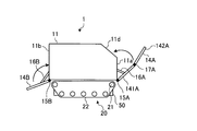
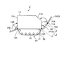
- FIG. 1 is a schematic perspective view of an amphibious vehicle 1 according to a first embodiment of the present invention.
- 2 and 3 are side views of the amphibious vehicle 1 according to the first embodiment of the present invention.
- the amphibious vehicle 1 according to the present embodiment includes a vehicle body 11 having a generally rectangular parallelepiped shape and a traveling device 20 provided at lower portions on both sides of the vehicle body 11. .
- the vehicle main body 11 is provided with a propulsion device (not shown) provided with a propeller or a water jet used in the water navigation mode.
- the traveling device 20 includes a sprocket 21 that is rotationally driven by a driving device (not shown) such as an engine, and a crawler belt 22 that is rotationally driven by the sprocket 21.
- a vehicle window 13 is provided on the upper portion of the front surface 11 a in the traveling direction Fr of the vehicle body 11, and the driver can visually recognize the outside from the vehicle window 13.
- the example which drives the vehicle main body 11 with the traveling apparatus 20 which has the crawler belt 22 was demonstrated in FIG. 1, it may replace with the crawler belt 22 and the traveling apparatus which has a tire may be used.
- a front flap (front plate member) 14A is fixed to the lower end of the front surface 11a of the vehicle body 11.
- the front flap 14A is attached to the lower end of the front surface 11a of the vehicle body 11 via a hinge 15A so that the main surface 14a (see FIG. 5) is inclined with respect to the front surface 11a of the vehicle body 11.
- the front flap 14 ⁇ / b> A has a width corresponding to the vehicle width of the vehicle body 11.
- the front flap 14A has a lower flap 141A having one end fixed to the lower end of the front surface 11a of the vehicle body 11, and one end connected to the other end of the lower flap 141A via a hinge 17A.
- the front flap 14 ⁇ / b> A has a main surface 14 a at a predetermined angle ⁇ ⁇ b> 1 (see FIG. 5) with the front surface 11 a of the vehicle body 11 via an extendable support member 16 ⁇ / b> A having one end fixed to the lower end of the vehicle body 11. It is attached to make.
- the lower flap 141A has a width corresponding to the front surface 11a of the vehicle main body 11, and the lower flap 141A is rotatable relative to the front surface 11a of the vehicle main body 11 via the hinge 15A and the support member 16A.
- the main body 11 is fixed to the lower end of the front surface 11a.
- the upper flap 142A has a width corresponding to the inclined surface 11d of the vehicle main body 11, and is fixed so as to be rotatable relative to the lower flap 141A via a hinge 17A.
- the lower flap 141A is configured to be fixed to the front surface 11a of the vehicle body 11 by a fixing member (not shown).
- the upper flap 142A is configured to be fixable to the slope 11d of the front surface 11a of the vehicle body 11 by a fixing member (not shown).
- the support member 16 ⁇ / b> A is provided to be extendable in the front-rear direction in the traveling direction of the vehicle body 11.
- lower flap 141A may drive hinge 15A by a drive part (not shown), and may fix a main surface with respect to the front surface 11a of vehicle main body 11 so that rotation is possible, and drive part (not shown). You may drive 16 A of support members, and may fix a main surface with respect to the front surface 11a of the vehicle main body 11 so that rotation is possible.
- the upper flap 142A may drive the hinge 17A by a drive unit (not shown) and fix the main surface to the front surface 11a of the vehicle body 11 so as to be rotatable.
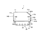
- a rear flap (rear plate member) 14B is fixed to the lower end portion of the rear surface 11b of the vehicle main body 11.
- the rear flap 14B is attached to the lower end portion of the rear surface 11b of the vehicle main body 11 via a hinge 15B so that the main surface 14b (see FIG. 5) is inclined with respect to the rear surface 11b of the vehicle main body 11.
- the rear flap 14 ⁇ / b> B has a width corresponding to the vehicle width of the vehicle body 11.
- the rear flap 14B has a main surface 14b at a predetermined angle ⁇ 2 (see FIG. 5) with the rear surface 11b of the vehicle body 11 via an extendable support member 16B having one end fixed to the lower end of the vehicle body 11. It is attached to make.
- the rear flap 14B on the rear surface 11b side of the vehicle main body 11 is fixed so as to be rotatable relative to the rear surface 11b of the vehicle main body 11 via the hinge 15B.
- the rear flap 14B is configured to be fixable to the rear surface 11b of the vehicle main body 11 by a fixing member (not shown).
- the rear flap 14B may drive the hinge 15B by a driving unit (not shown) to fix the main surface 14b to the rear surface 11b of the vehicle body 11 so as to be rotatable, and the driving unit (not shown).
- the support member 16B may be driven to fix the main surface to the rear surface 11b of the vehicle body 11 so as to be rotatable.
- the lower flap 141A of the front flap 14A can be fixed to the front surface 11a of the vehicle body 11, and the upper flap 142A can be fixed to the slope 11d.
- the rear flap 14 ⁇ / b> B can be fixed to the rear surface 11 b of the vehicle main body 11.
- the support member 16A can be accommodated in an accommodation space (not shown) provided in the front surface 11a of the vehicle body 11, and the support member 16B is accommodated in an accommodation space (not shown) provided in the rear surface 11b of the vehicle body 11. Is possible.
- the amphibious vehicle 1 is configured so that the front flap 14A provided on the front side of the vehicle main body 11 is foldable by the lower flap 141A and the upper flap 142A that can be folded with respect to each other.
- the front flap 14A can be compactly fixed to the front surface 11a of the vehicle body 11 when landing on the vehicle.
- the rear flap 14B provided on the rear side of the vehicle main body 11 can be similarly compactly fixed to the rear surface 11b of the vehicle main body 11.
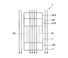
- a pair of keels (rectifying members) 50 are provided on the bottom surface 11 c of the vehicle body 11 along the traveling device 20 provided at the lower portions on both sides of the vehicle body 11.
- the keel 50 has a substantially rectangular parallelepiped shape, and extends from the front side to the rear side of the vehicle body 11 and is provided in the vicinity of the traveling device 20. Further, the keel 50 is provided so as to cover the lower side of the traveling device 20.
- the keel 50 has a substantially rectangular parallelepiped shape.
- the shape of the keel 50 the water flow flowing on the lower surface side of the vehicle body 11 when the vehicle body 11 travels on the water is rectified. If it can stabilize the attitude
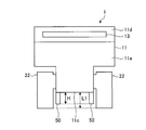
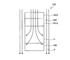
- FIG. 4 is a schematic front view of the amphibious vehicle 1 according to the present embodiment.
- the front flap 14A is omitted.
- the pair of keels 50 are provided at both ends of the bottom surface 11 c of the vehicle body 11.
- the keel 50 has a height H from the vehicle bottom surface 11c toward the lower side of the vehicle main body 11 slightly lower than the distance L1 between the bottom surface 11c of the vehicle main body 11 and the lower surface of the crawler belt 22 of the traveling device 20. Thus, it is attached to the lower surface of the vehicle body 11.
- the pair of keels 50 By providing the pair of keels 50 in this way, it is possible to prevent the contact between the pair of keels 50 and the road surface when the amphibious vehicle 1 travels on land. Moreover, since it becomes possible to fully cover the inner surface of the crawler belt 22 of the traveling device 20 by the pair of keels 50, the buoyancy by the pair of keels 50 can be sufficiently obtained when the amphibious vehicle 1 travels on the water. The wave resistance acting on the main body 11 can be reduced. Note that the pair of keels 50 is not necessarily provided at both ends of the bottom surface 11c of the vehicle body 11, and may be provided at both ends. Further, the height H of the keel 50 can be changed as appropriate within the range where the effects of the present invention are exhibited.
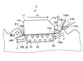
- FIG. 5 is a side view of the amphibious vehicle 1 at the time of water navigation.
- the front surface 11a of the vehicle body 11 is such that the main surface 14a of the front flap 14A is at an acute angle ⁇ 1 with respect to the front surface 11a of the vehicle body 11.
- 14A of front flaps are attached to the lower end part.
- the amphibious vehicle 1 moves upward from the lower side of the front surface 11a side of the vehicle main body 11 because the waves on the water run backward from the lower surface of the front flap 14A through the bottom surface 11c of the vehicle main body 11 when traveling on the water.
- Lifting force acts on the vehicle body 11, and it is possible to reduce the wave-making resistance from the front surface 11a of the vehicle body 11.
- the vehicle main body 11 becomes a sliding type, so that the posture of the vehicle main body 11 is stabilized and the vehicle main body 11 is stable. It becomes possible to prevent submergence of the front part of the.
- the pair of keels 50 provided on the bottom surface 11c of the vehicle main body 11 causes the water flow from the front side of the vehicle main body 11 to be rectified to the rear side of the vehicle main body 11.
- Flowing. 6A and 6B are explanatory diagrams of the water flow with respect to the amphibious vehicle 1. As shown in FIG. 6A, in the amphibious vehicle 1 including the pair of keels 50, the water flow F flowing from the lower side of the front flap 14 ⁇ / b> A toward the lower side of the vehicle body 11 is rectified by the pair of keels 50.
- the rear flap is formed at the lower end of the rear surface 11b of the vehicle body 11 so that the main surface 14b of the rear flap 14B has an obtuse angle ⁇ 2 with respect to the rear surface 11b of the vehicle body 11. 14B is attached.
- the rear flap 14B is preferably provided at the lower end of the rear surface 11b of the vehicle body 11 from the viewpoint of further improving the above-described operational effects.
- the amphibious vehicle 1 when the amphibious vehicle 1 travels on the water, the vehicle main body 11 is moved from the front side of the vehicle main body 11 through the lower surface side of the front flap 14A. Since the water flow flowing on the lower surface side is rectified by the pair of keels 50 and flows to the rear side of the vehicle main body 11, it is possible to prevent the generation of water flows flowing on both sides of the vehicle main body 11 by the bottom surface 11 c of the vehicle main body 11. . As a result, the amphibious vehicle 1 can prevent the traveling device 20 on the lower side of the vehicle body 11 from coming into contact with the water flow on the lower side of the vehicle body 11. It is possible to reduce the resistance acting on the vehicle body 11 and improve the propulsion performance.
- the front flap 14A and the rear flap 14B are attached to the vehicle main body 11 by the hinges 15A and 15B
- the front flap 14A and the rear flap 14B are the front surface 11a of the vehicle main body 11.
- the main surfaces 14a and 14b can be fixed to the rear surface 11b at predetermined angles ⁇ 1 and ⁇ 2, it is not always necessary to fix the hinges 15A and 15B.
- the example in which the front flap 14A and the rear flap 14B are fixed to the vehicle body 11 by the support members 16A and 16B has been described.
- the front flap 14A and the rear flap 14B are not necessarily the support member 16A.
- the front flap 14A is configured by two plate-shaped members of the lower flap 141A and the upper flap 142A has been described, but the front flap 14A is configured by one plate-shaped member. May be.
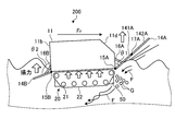
- FIG. 7 is a side view of the amphibious vehicle 2 according to the second embodiment of the present invention.
- the amphibious vehicle 2 according to the present embodiment is a rear end that is a connecting portion with the vehicle main body 11 instead of the lower flap 141A of the front flap 14A of the amphibious vehicle 1 according to the first embodiment described above.
- a lower flap 143 having a curved portion is provided.
- the lower flap 143 has a curved portion 143a having a radius of curvature of about 2 / 5R to 4 / 5R, for example, with respect to the distance L2 between the lower flap 143 and the upper flap 142A.
- connection portion between the lower flap 143 and the vehicle main body 11 can be made smooth.
- description is abbreviate
- FIG. 8A and FIG. 8B are explanatory diagrams of the water flow when the amphibious vehicle 2 according to the second embodiment travels on the water.
- the amphibious vehicle 2 including the lower flap 143 provided with the curved portion 143 a travels on the water
- the water from the front side of the vehicle body 11 is transferred to the lower surface of the lower flap 143.
- the connecting portion between the lower flap 143 and the vehicle main body 11 is in a smooth state by the curved portion 143a
- the water flow F flowing from the lower side of the lower flap 143 to the lower surface side of the vehicle main body 11 It is not contained but rectified and turbulent flow does not occur.
- this water flow F which does not contain the air G flows toward the rear flap 14B on the rear side of the vehicle body 11 while being further rectified by the pair of keels 50, the wave-making resistance against the vehicle body 11 can be further reduced. It becomes possible.
Abstract
The purpose of the present invention is to provide an amphibious vehicle such that wave-making resistance when travelling on water is reduced and the propulsive performance of the vehicle body is improved. The amphibious vehicle 1 according to the present invention is characterized by comprising: a vehicle body 11 that is capable of moving on land and in water; a front flap 14A where a rear end is fixed to the lower end of the vehicle body 11; and a rear flap 14B where a front end is fixed to a rear portion of the vehicle body 11; and a pair of keels 50 that are disposed along travelling devices 20 provided on both sides of the bottom 11c of the vehicle body 11.
Description
本発明は、水陸両用車に関し、例えば、車両本体に板状部材が設けられた水陸両用車に関する。
The present invention relates to an amphibious vehicle, for example, an amphibious vehicle in which a plate-like member is provided on a vehicle body.
従来、船体の底面の中心にキールが設けられた水陸両用車用の船体が提案されている(例えば、特許文献1参照)。この水陸両用車用の船体においては、船体の滑走面内の不連続部を覆う滑走板をキールから等距離となるように配置することにより、船体の剛性を向上させて推進性能を向上させている。
Conventionally, a hull for an amphibious vehicle in which a keel is provided at the center of the bottom of the hull has been proposed (see, for example, Patent Document 1). In this amphibious hull, the hull rigidity is improved by improving the propulsion performance by arranging the planing plates that cover the discontinuities in the hull's planing surface so that they are equidistant from the keel. Yes.
ところで、水陸両用車においては、車両の前後にフラップを設けることによって水上航走時の推進性能を向上させる検討がなされている。しかしながら、車両の前後にフラップを設けても、例えば、車両を水上で高速航走(例えば、14km/h以上)する場合においては、車体に作用する揚力が十分に得られずに、車体に作用する造波抵抗が増大して必ずしも十分な水上航走時の推進性能が得られない場合がある。
By the way, in amphibious vehicles, investigations have been made to improve the propulsion performance at the time of surface navigation by providing flaps at the front and rear of the vehicle. However, even if flaps are provided at the front and rear of the vehicle, for example, when the vehicle travels at high speed on the water (for example, 14 km / h or more), the lift acting on the vehicle body cannot be obtained sufficiently, and the vehicle does not act on the vehicle body. In some cases, the wave-making resistance increases, and sufficient propulsion performance at the time of water navigation is not obtained.
本発明は、このような実情に鑑みてなされたものであり、水上航走時の造波抵抗を低減でき、車両本体の推進性能を向上できる水陸両用車を提供することを目的とする。
This invention is made in view of such a situation, and it aims at providing the amphibious vehicle which can reduce the wave-making resistance at the time of surface navigation, and can improve the propulsion performance of a vehicle main body.
本発明の水陸両用車は、水上及び陸上を移動可能な車両本体と、前記車両本体の下端部に後端部が固定された前部板状部材と、前記車両本体の後部に前端部が固定された後部板状部材と、前記車両本体の底面における前記車両本体の両側方に設けられた走行装置に沿って設けられた一対の整流部材と、を具備することを特徴とする。
The amphibious vehicle of the present invention includes a vehicle main body movable on the water and land, a front plate member having a rear end fixed to the lower end of the vehicle main body, and a front end fixed to the rear of the vehicle main body. And a pair of rectifying members provided along traveling devices provided on both sides of the vehicle main body on the bottom surface of the vehicle main body.
この構成によれば、水陸両用車の水上航走時に車両本体の前方側から前部板状部材の下面側を介して車両本体の下面側に流れる水流が、一対の整流部材によって整流されて車両本体の後方側に流れるので、車両本体の底面によって車両本体の両側方に押し出される水流の発生を防ぐことが可能となる。これにより、水陸両用車は、車両本体の下方側で走行装置と接触する水流の発生を防ぐことが可能となるので、水上航走時の造波抵抗を低減でき、車両本体に作用する抵抗を低減して推進性能を向上することが可能となる。
According to this configuration, the water flow that flows from the front side of the vehicle main body to the lower surface side of the front plate-like member when the amphibious vehicle is traveling on the water is rectified by the pair of rectifying members. Since it flows to the rear side of the main body, it is possible to prevent the generation of water flow pushed out to both sides of the vehicle main body by the bottom surface of the vehicle main body. As a result, the amphibious vehicle can prevent the generation of a water flow that contacts the traveling device on the lower side of the vehicle body, so that the wave-making resistance at the time of surface navigation can be reduced, and the resistance acting on the vehicle body can be reduced. It becomes possible to reduce and improve propulsion performance.
本発明の水陸両用車においては、前記整流部材は、前記走行装置の側面を覆うように設けられたことが好ましい。この構成により、整流部材によって車両本体の下方側の水流を十分に整流することが可能となるので、車両本体の下方側における走行装置と水流との接触を防ぐことが可能となり、水上航走時の造波抵抗をより一層低減できる。
In the amphibious vehicle of the present invention, it is preferable that the rectifying member is provided so as to cover a side surface of the traveling device. With this configuration, since the water flow on the lower side of the vehicle main body can be sufficiently rectified by the rectifying member, it becomes possible to prevent the traveling device and the water flow on the lower side of the vehicle main body from contacting, The wave resistance can be further reduced.
本発明の水陸両用車においては、前記整流部材は、前記車両本体の前端部から後端部に向けて延在することが好ましい。この構成により、整流部材によって車両本体の下方側の水流を十分に整流することが可能となるので、車両本体の下方側における走行装置と水流との接触を防ぐことが可能となり、水上航走時の造波抵抗をより一層低減できる。
In the amphibious vehicle of the present invention, it is preferable that the rectifying member extends from the front end portion of the vehicle main body toward the rear end portion. With this configuration, since the water flow on the lower side of the vehicle main body can be sufficiently rectified by the rectifying member, it becomes possible to prevent the traveling device and the water flow on the lower side of the vehicle main body from contacting, The wave resistance can be further reduced.
本発明の水陸両用車においては、前記前部板状部材は、後端部に湾曲部を有することが好ましい。この構成により、車両本体と前部板状部材との接続部が滑らかな状態となるので、下面側に流れる水流の空気の含有を防ぐことが可能となる。そして、この空気を含有しない水流が一対の整流部材によって更に整流されながら車両本体の後方側の後部板状部材に向かって流れるので、車両本体に対する造波抵抗をより一層低減することが可能となる。
In the amphibious vehicle of the present invention, the front plate member preferably has a curved portion at the rear end. With this configuration, the connection portion between the vehicle main body and the front plate-like member is in a smooth state, so that it is possible to prevent the inclusion of air in the water stream flowing on the lower surface side. And since the water flow which does not contain air flows toward the rear plate member on the rear side of the vehicle body while being further rectified by the pair of rectification members, it is possible to further reduce the wave-making resistance against the vehicle body. .
本発明の水陸両用車においては、前記前部板状部材が、前記車両本体の前面の下端部に後端部が固定された下部板状部材と、前記下部板状部材の前端部に前記下部板状部材に対して相対的に回動可能に連結された上部板状部材とを備えることが好ましい。この構成により、水陸両用車は、車両本体の前方側に設けられた前部板状部材を折り畳んで収納することが可能となるので、水上から陸地に上陸した際に前部板状部材を車両本体の前面にコンパクトに収容することが可能となる。
In the amphibious vehicle of the present invention, the front plate-shaped member includes a lower plate-shaped member whose rear end is fixed to the lower end of the front surface of the vehicle main body, and the lower portion on the front end of the lower plate-shaped member. It is preferable to include an upper plate-shaped member that is rotatably connected to the plate-shaped member. With this configuration, the amphibious vehicle can fold and store the front plate-like member provided on the front side of the vehicle body, so that the front plate-like member is mounted on the vehicle when landing on the land from the water. It becomes possible to accommodate in the front of the main body in a compact manner.
本発明の水陸両用車においては、前記前部板状部材が、前記車両本体との接続部を回転軸として回動可能に前記車両本体に固定されてなることが好ましい。この構成により、水陸両用車は、前部板状部材を回動させることにより車両本体に作用する揚力を調整することが可能となるので、車両本体に対する波に対して常に最適な車両姿勢をとることが可能となり、最高速度が向上するだけでなく、車両本体の搖動の抑制が可能となり乗り心地を改善できると共に、安全性を向上することが可能となる。
In the amphibious vehicle of the present invention, it is preferable that the front plate-like member is fixed to the vehicle body so as to be rotatable about a connecting portion with the vehicle body as a rotation axis. With this configuration, the amphibious vehicle can adjust the lift acting on the vehicle main body by rotating the front plate-like member, so that it always takes the optimum vehicle posture with respect to the waves with respect to the vehicle main body. As a result, not only the maximum speed can be improved, but also the peristalsis of the vehicle body can be suppressed, so that the riding comfort can be improved and the safety can be improved.
本発明の水陸両用車においては、前記後部板状部材が、前記車両本体との接続部を回転軸として回動可能に前記車両本体に固定されてなることが好ましい。この構成により、水陸両用車は、後部板状部材を回動させることにより車両本体に作用する揚力を調整することが可能となるので、車両本体に対する波に対して常に最適な車両姿勢をとることが可能となり、最高速度が向上するだけでなく、車両本体の搖動の抑制が可能となり乗り心地を改善できると共に、安全性を向上することが可能となる。
In the amphibious vehicle of the present invention, it is preferable that the rear plate-like member is fixed to the vehicle body so as to be rotatable about a connecting portion with the vehicle body as a rotation axis. With this configuration, the amphibious vehicle can adjust the lift acting on the vehicle main body by rotating the rear plate member, so that it always takes the optimum vehicle posture with respect to the waves against the vehicle main body. Thus, not only the maximum speed can be improved, but also the peristalsis of the vehicle body can be suppressed, so that the ride comfort can be improved and the safety can be improved.
本発明の水陸両用車においては、前記前部板状部材が、前記車両本体の前面に対して固定可能であることが好ましい。この構成により、水陸両用車は、車両本体の前面に前部板状部材を固定することが可能となるので、前部板状部材を車両本体の前面にコンパクトに収容することが可能となる。
In the amphibious vehicle of the present invention, it is preferable that the front plate member can be fixed to the front surface of the vehicle body. With this configuration, the amphibious vehicle can fix the front plate-like member on the front surface of the vehicle main body, so that the front plate-like member can be compactly accommodated on the front surface of the vehicle main body.
本発明の水陸両用車においては、前記後部板状部材は、前記車両本体の後面に対して固定可能であることが好ましい。この構成により、水陸両用車は、車両本体の後面に後部板状部材を固定することが可能となるので、後部板状部材を車両本体の後面にコンパクトに収容することが可能となる。
In the amphibious vehicle of the present invention, it is preferable that the rear plate member can be fixed to the rear surface of the vehicle body. With this configuration, the amphibious vehicle can fix the rear plate-like member to the rear surface of the vehicle main body, so that the rear plate-like member can be compactly accommodated on the rear surface of the vehicle main body.
本発明によれば、水上航走時の造波抵抗を低減でき、車両本体の推進性能を向上できる水陸両用車を実現できる。
According to the present invention, it is possible to realize an amphibious vehicle that can reduce the wave-making resistance at the time of surface navigation and improve the propulsion performance of the vehicle body.
以下、本発明の一実施の形態について、添付図面を参照して詳細に説明する。なお、以下の各実施の形態に限定されるものではなく、適宜変更して実施可能である。また、以下の各実施の形態は適宜組み合わせて実施可能である。また、各実施の形態において共通する構成要素には同一の符号を付し、説明の重複を避ける。
Hereinafter, an embodiment of the present invention will be described in detail with reference to the accompanying drawings. In addition, it is not limited to each following embodiment, It can implement by changing suitably. Also, the following embodiments can be implemented in combination as appropriate. Moreover, the same code | symbol is attached | subjected to the component which is common in each embodiment, and duplication of description is avoided.
(第1の実施の形態)
図1は、本発明の第1の実施の形態に係る水陸両用車1の模式的な斜視図である。図2及び図3は、本発明の第1の実施の形態に係る水陸両用車1の側面図である。図1~図3に示すように、本実施の形態に係る水陸両用車1は、概して直方体形状の車両本体11と、この車両本体11の両側方の下部に設けられた走行装置20とを備える。車両本体11には、水上航走モードで使用するプロペラ又はウォータジェットを備えた推進器(不図示)が設けられている。走行装置20は、エンジンなどの駆動装置(不図示)により回転駆動されるスプロケット21と、このスプロケット21により回転駆動される履帯22とを備える。この水陸両用車1においては、車両本体11の走行方向Frにおける前面11aの上部には車窓13が設けられており、この車窓13から運転者が外部を視認可能になっている。なお、図1においては、履帯22を有する走行装置20によって車両本体11を駆動する例について説明したが、履帯22に代えてタイヤを有する走行装置を用いてもよい。 (First embodiment)
FIG. 1 is a schematic perspective view of anamphibious vehicle 1 according to a first embodiment of the present invention. 2 and 3 are side views of the amphibious vehicle 1 according to the first embodiment of the present invention. As shown in FIGS. 1 to 3, the amphibious vehicle 1 according to the present embodiment includes a vehicle body 11 having a generally rectangular parallelepiped shape and a traveling device 20 provided at lower portions on both sides of the vehicle body 11. . The vehicle main body 11 is provided with a propulsion device (not shown) provided with a propeller or a water jet used in the water navigation mode. The traveling device 20 includes a sprocket 21 that is rotationally driven by a driving device (not shown) such as an engine, and a crawler belt 22 that is rotationally driven by the sprocket 21. In this amphibious vehicle 1, a vehicle window 13 is provided on the upper portion of the front surface 11 a in the traveling direction Fr of the vehicle body 11, and the driver can visually recognize the outside from the vehicle window 13. In addition, although the example which drives the vehicle main body 11 with the traveling apparatus 20 which has the crawler belt 22 was demonstrated in FIG. 1, it may replace with the crawler belt 22 and the traveling apparatus which has a tire may be used.
図1は、本発明の第1の実施の形態に係る水陸両用車1の模式的な斜視図である。図2及び図3は、本発明の第1の実施の形態に係る水陸両用車1の側面図である。図1~図3に示すように、本実施の形態に係る水陸両用車1は、概して直方体形状の車両本体11と、この車両本体11の両側方の下部に設けられた走行装置20とを備える。車両本体11には、水上航走モードで使用するプロペラ又はウォータジェットを備えた推進器(不図示)が設けられている。走行装置20は、エンジンなどの駆動装置(不図示)により回転駆動されるスプロケット21と、このスプロケット21により回転駆動される履帯22とを備える。この水陸両用車1においては、車両本体11の走行方向Frにおける前面11aの上部には車窓13が設けられており、この車窓13から運転者が外部を視認可能になっている。なお、図1においては、履帯22を有する走行装置20によって車両本体11を駆動する例について説明したが、履帯22に代えてタイヤを有する走行装置を用いてもよい。 (First embodiment)
FIG. 1 is a schematic perspective view of an
車両本体11の前面11aの下端部には前部フラップ(前部板状部材)14Aの一端部が固定されている。この前部フラップ14Aは、車両本体11の前面11aに対して主面14a(図5参照)が傾斜するように、ヒンジ15Aを介して車両本体11の前面11aの下端部に取り付けられている。前部フラップ14Aは、車両本体11の車幅に対応した幅を有している。前部フラップ14Aは、車両本体11の前面11aの下端部に一端部が固定された下部フラップ(下部板状部材)141Aと、この下部フラップ141Aの他端部にヒンジ17Aを介して一端部が固定された上部フラップ(上部板状部材)142Aとを備える。前部フラップ14Aは、車両本体11の下端部に一端が固定された伸縮可能な支持部材16Aを介して車両本体11の前面11aとの間で主面14aが所定の角度θ1(図5参照)をなすように取り付けられている。
One end of a front flap (front plate member) 14A is fixed to the lower end of the front surface 11a of the vehicle body 11. The front flap 14A is attached to the lower end of the front surface 11a of the vehicle body 11 via a hinge 15A so that the main surface 14a (see FIG. 5) is inclined with respect to the front surface 11a of the vehicle body 11. The front flap 14 </ b> A has a width corresponding to the vehicle width of the vehicle body 11. The front flap 14A has a lower flap 141A having one end fixed to the lower end of the front surface 11a of the vehicle body 11, and one end connected to the other end of the lower flap 141A via a hinge 17A. 142A of fixed upper flaps (upper plate-shaped member). The front flap 14 </ b> A has a main surface 14 a at a predetermined angle θ <b> 1 (see FIG. 5) with the front surface 11 a of the vehicle body 11 via an extendable support member 16 </ b> A having one end fixed to the lower end of the vehicle body 11. It is attached to make.
下部フラップ141Aは、主面が車両本体11の前面11aに対応した幅を有しており、ヒンジ15A及び支持部材16Aを介して車両本体11の前面11aに対して相対的に回動可能に車両本体11の前面11aの下端部に固定されている。上部フラップ142Aは、主面が車両本体11の斜面11dに対応した幅を有しており、ヒンジ17Aを介して下部フラップ141Aに対して相対的に回動可能に固定されている。下部フラップ141Aは、固定部材(不図示)によって車両本体11の前面11aに固定可能に構成されている。上部フラップ142Aは、固定部材(不図示)によって車両本体11の前面11aの斜面11dに固定可能に構成されている。支持部材16Aは、車両本体11の進行方向における前後方向に伸縮可能に設けられている。
The lower flap 141A has a width corresponding to the front surface 11a of the vehicle main body 11, and the lower flap 141A is rotatable relative to the front surface 11a of the vehicle main body 11 via the hinge 15A and the support member 16A. The main body 11 is fixed to the lower end of the front surface 11a. The upper flap 142A has a width corresponding to the inclined surface 11d of the vehicle main body 11, and is fixed so as to be rotatable relative to the lower flap 141A via a hinge 17A. The lower flap 141A is configured to be fixed to the front surface 11a of the vehicle body 11 by a fixing member (not shown). The upper flap 142A is configured to be fixable to the slope 11d of the front surface 11a of the vehicle body 11 by a fixing member (not shown). The support member 16 </ b> A is provided to be extendable in the front-rear direction in the traveling direction of the vehicle body 11.
なお、下部フラップ141Aは、駆動部(不図示)によってヒンジ15Aを駆動して車両本体11の前面11aに対して主面を回動可能に固定してもよく、また駆動部(不図示)によって支持部材16Aを駆動して車両本体11の前面11aに対して主面を回動可能に固定してもよい。また、上部フラップ142Aは、駆動部(不図示)によってヒンジ17Aを駆動して車両本体11の前面11aに対して主面を回動可能に固定してもよい。
In addition, lower flap 141A may drive hinge 15A by a drive part (not shown), and may fix a main surface with respect to the front surface 11a of vehicle main body 11 so that rotation is possible, and drive part (not shown). You may drive 16 A of support members, and may fix a main surface with respect to the front surface 11a of the vehicle main body 11 so that rotation is possible. The upper flap 142A may drive the hinge 17A by a drive unit (not shown) and fix the main surface to the front surface 11a of the vehicle body 11 so as to be rotatable.
また、車両本体11の後面11bの下端部には、後部フラップ(後部板状部材)14Bの一端部が固定されている。この後部フラップ14Bは、車両本体11の後面11bに対して主面14b(図5参照)が傾斜するように、ヒンジ15Bを介して車両本体11の後面11bの下端部に取り付けられている。後部フラップ14Bは、車両本体11の車幅に対応した幅を有している。後部フラップ14Bは、車両本体11の下端部に一端が固定された伸縮可能な支持部材16Bを介して車両本体11の後面11bとの間で主面14bが所定の角度θ2(図5参照)をなすように取り付けられている。
Further, one end of a rear flap (rear plate member) 14B is fixed to the lower end portion of the rear surface 11b of the vehicle main body 11. The rear flap 14B is attached to the lower end portion of the rear surface 11b of the vehicle main body 11 via a hinge 15B so that the main surface 14b (see FIG. 5) is inclined with respect to the rear surface 11b of the vehicle main body 11. The rear flap 14 </ b> B has a width corresponding to the vehicle width of the vehicle body 11. The rear flap 14B has a main surface 14b at a predetermined angle θ2 (see FIG. 5) with the rear surface 11b of the vehicle body 11 via an extendable support member 16B having one end fixed to the lower end of the vehicle body 11. It is attached to make.
また、水陸両用車1は、車両本体11の後面11b側の後部フラップ14Bが、ヒンジ15Bを介して車両本体11の後面11bに対して相対的に回動可能に固定されている。後部フラップ14Bは、固定部材(不図示)によって車両本体11の後面11bに固定可能に構成されている。なお、後部フラップ14Bは、駆動部(不図示)によってヒンジ15Bを駆動して車両本体11の後面11bに対して主面14bを回動可能に固定してもよく、また駆動部(不図示)によって支持部材16Bを駆動して車両本体11の後面11bに対して主面を回動可能に固定してもよい。
Further, in the amphibious vehicle 1, the rear flap 14B on the rear surface 11b side of the vehicle main body 11 is fixed so as to be rotatable relative to the rear surface 11b of the vehicle main body 11 via the hinge 15B. The rear flap 14B is configured to be fixable to the rear surface 11b of the vehicle main body 11 by a fixing member (not shown). The rear flap 14B may drive the hinge 15B by a driving unit (not shown) to fix the main surface 14b to the rear surface 11b of the vehicle body 11 so as to be rotatable, and the driving unit (not shown). Thus, the support member 16B may be driven to fix the main surface to the rear surface 11b of the vehicle body 11 so as to be rotatable.
この水陸両用車1においては、例えば、陸上走行時には、前部フラップ14Aの下部フラップ141Aを車両本体11の前面11aに固定し、斜面11dに上部フラップ142Aを固定することが可能である。また、この水陸両用車1においては、後部フラップ14Bを車両本体11の後面11bに固定することが可能である。支持部材16Aは、車両本体11の前面11aに設けられた収容空間(不図示)に収容可能であり、支持部材16Bは、車両本体11の後面11bに設けられた収容空間(不図示)に収容可能である。このように、この水陸両用車1は、車両本体11の前方側に設けられた前部フラップ14Aを相互に折り畳み可能な下部フラップ141A及び上部フラップ142Aによって折り畳み可能に構成することにより、水上から陸地に上陸した際に前部フラップ14Aを車両本体11の前面11aにコンパクトに固定することが可能となる。そして、車両本体11の後方側に設けられた後部フラップ14Bも同様に車両本体11の後面11bに対してコンパクトに固定することが可能となる。
In the amphibious vehicle 1, for example, when traveling on land, the lower flap 141A of the front flap 14A can be fixed to the front surface 11a of the vehicle body 11, and the upper flap 142A can be fixed to the slope 11d. In the amphibious vehicle 1, the rear flap 14 </ b> B can be fixed to the rear surface 11 b of the vehicle main body 11. The support member 16A can be accommodated in an accommodation space (not shown) provided in the front surface 11a of the vehicle body 11, and the support member 16B is accommodated in an accommodation space (not shown) provided in the rear surface 11b of the vehicle body 11. Is possible. As described above, the amphibious vehicle 1 is configured so that the front flap 14A provided on the front side of the vehicle main body 11 is foldable by the lower flap 141A and the upper flap 142A that can be folded with respect to each other. The front flap 14A can be compactly fixed to the front surface 11a of the vehicle body 11 when landing on the vehicle. Then, the rear flap 14B provided on the rear side of the vehicle main body 11 can be similarly compactly fixed to the rear surface 11b of the vehicle main body 11.
車両本体11の底面11cには、車両本体11の両側方の下部に設けられた走行装置20に沿って一対のキール(整流部材)50が設けられている。このキール50は、概略直方体形状をなしており、車両本体11の前方側から後方側に向けて延在して走行装置20の近傍に設けられている。また、キール50は、走行装置20の下部の側方を覆うように設けられている。このようにキール50を設けることにより、車両本体11の両側方がキール50によって囲われるので、車両本体11に作用する圧力が高まり、水陸両用車1が水上を航走する際に車両本体11の下部を流れる水流が整流されて車両本体11に作用する揚力が向上する。したがって、水陸両用車1の水上航走時に車両本体11の全体に作用する浮力が向上するので、車両本体11の抵抗低減を実現できる。なお、本実施の形態では、キール50が概略直方体形状である例について説明するが、キール50の形状としては、車両本体11の水上航走時に車両本体11の下面側を流れる水流を整流して車両本体11の姿勢を安定できるものであれば特に制限はなく、例えば、三角柱形状などの多角柱形状、円柱形状などの各種形状を用いることが可能である。
A pair of keels (rectifying members) 50 are provided on the bottom surface 11 c of the vehicle body 11 along the traveling device 20 provided at the lower portions on both sides of the vehicle body 11. The keel 50 has a substantially rectangular parallelepiped shape, and extends from the front side to the rear side of the vehicle body 11 and is provided in the vicinity of the traveling device 20. Further, the keel 50 is provided so as to cover the lower side of the traveling device 20. By providing the keel 50 in this way, both sides of the vehicle main body 11 are surrounded by the keel 50, so that the pressure acting on the vehicle main body 11 increases, and the amphibious vehicle 1 travels on the water when the amphibious vehicle 1 travels on the water. The water flow flowing through the lower portion is rectified, and the lift acting on the vehicle body 11 is improved. Therefore, since the buoyancy acting on the entire vehicle body 11 when the amphibious vehicle 1 travels on the water is improved, the resistance of the vehicle body 11 can be reduced. In the present embodiment, an example in which the keel 50 has a substantially rectangular parallelepiped shape will be described. However, as the shape of the keel 50, the water flow flowing on the lower surface side of the vehicle body 11 when the vehicle body 11 travels on the water is rectified. If it can stabilize the attitude | position of the vehicle main body 11, there will be no restriction | limiting in particular, For example, various shapes, such as polygonal column shape, such as a triangular prism shape, and a cylindrical shape, can be used.
図4は、本実施の形態に係る水陸両用車1の模式的な正面図である。なお、図4においては、説明の便宜上、前部フラップ14Aを省略して示している。図4に示すように、一対のキール50は、車両本体11の底面11cの両端にそれぞれ設けられている。また、キール50は、車両底面11cから車両本体11の下方側に向けた高さHが、車両本体11の底面11cと走行装置20の履帯22の下面との間の距離L1より僅かに低くなるように車両本体11の下面に取り付けられている。このように一対のキール50を設けることにより、水陸両用車1の陸上走行時に一対のキール50と路面との接触を防ぐことが可能となる。また、一対のキール50によって走行装置20の履帯22の内側面を十分に覆うことが可能となるので、水陸両用車1の水上航走時に一対のキール50による浮力が十分に得られるので、車両本体11に作用する造波抵抗を低減できる。なお、一対のキール50は、必ずしも車両本体11の底面11cの両端に設ける必要はなく、両端部に設けてもよい。また、キール50の高さHは、本発明の効果を奏する範囲で適宜変更可能である。
FIG. 4 is a schematic front view of the amphibious vehicle 1 according to the present embodiment. In FIG. 4, for convenience of explanation, the front flap 14A is omitted. As shown in FIG. 4, the pair of keels 50 are provided at both ends of the bottom surface 11 c of the vehicle body 11. Further, the keel 50 has a height H from the vehicle bottom surface 11c toward the lower side of the vehicle main body 11 slightly lower than the distance L1 between the bottom surface 11c of the vehicle main body 11 and the lower surface of the crawler belt 22 of the traveling device 20. Thus, it is attached to the lower surface of the vehicle body 11. By providing the pair of keels 50 in this way, it is possible to prevent the contact between the pair of keels 50 and the road surface when the amphibious vehicle 1 travels on land. Moreover, since it becomes possible to fully cover the inner surface of the crawler belt 22 of the traveling device 20 by the pair of keels 50, the buoyancy by the pair of keels 50 can be sufficiently obtained when the amphibious vehicle 1 travels on the water. The wave resistance acting on the main body 11 can be reduced. Note that the pair of keels 50 is not necessarily provided at both ends of the bottom surface 11c of the vehicle body 11, and may be provided at both ends. Further, the height H of the keel 50 can be changed as appropriate within the range where the effects of the present invention are exhibited.
次に、本実施の形態に係る水陸両用車1の全体動作について説明する。図5は、水陸両用車1の水上航走時の側面図である。図5に示すように、本実施の形態に係る水陸両用車1においては、前部フラップ14Aの主面14aが車両本体11の前面11aに対して鋭角θ1となるように車両本体11の前面11aの下端部に前部フラップ14Aが取り付けられている。これにより、水陸両用車1は、水上航走時には水上の波が前部フラップ14Aの下面から車両本体11の底面11cを介して後方に抜けるので、車両本体11の前面11a側の下方から上方に向けて揚力が作用し、車両本体11の前面11aからの造波抵抗を低減することが可能となる。この結果、水陸両用車1を水上で高速航行(例えば、14km/h以上)させた場合であっても、車両本体11が滑走型となるので、車両本体11の姿勢が安定して車両本体11の前部の水没を防ぐことが可能となる。なお、上述した作用効果を一層向上する観点から、前部フラップ14Aは、車両本体11の前面11aの下端に設けることが好ましい。
Next, the overall operation of the amphibious vehicle 1 according to the present embodiment will be described. FIG. 5 is a side view of the amphibious vehicle 1 at the time of water navigation. As shown in FIG. 5, in the amphibious vehicle 1 according to the present embodiment, the front surface 11a of the vehicle body 11 is such that the main surface 14a of the front flap 14A is at an acute angle θ1 with respect to the front surface 11a of the vehicle body 11. 14A of front flaps are attached to the lower end part. As a result, the amphibious vehicle 1 moves upward from the lower side of the front surface 11a side of the vehicle main body 11 because the waves on the water run backward from the lower surface of the front flap 14A through the bottom surface 11c of the vehicle main body 11 when traveling on the water. Lifting force acts on the vehicle body 11, and it is possible to reduce the wave-making resistance from the front surface 11a of the vehicle body 11. As a result, even when the amphibious vehicle 1 is navigating at high speed on the water (for example, 14 km / h or more), the vehicle main body 11 becomes a sliding type, so that the posture of the vehicle main body 11 is stabilized and the vehicle main body 11 is stable. It becomes possible to prevent submergence of the front part of the. In addition, it is preferable to provide the front flap 14 </ b> A at the lower end of the front surface 11 a of the vehicle body 11 from the viewpoint of further improving the above-described operational effects.
また、本実施の形態に係る水陸両用車1においては、車両本体11の底面11cに設けた一対のキール50によって、車両本体11の前方側からの水流が整流されながら車両本体11の後方側に流れる。図6A及び図6Bは、水陸両用車1に対する水流の説明図である。図6Aに示すように、一対のキール50を備えた水陸両用車1においては、前部フラップ14Aの下方側から車両本体11の下方側に向けて流れる水流Fが、一対のキール50によって整流されるので、車両本体11の下部に設けられた走行装置20と水流Fの接触による車両本体11に対する造波抵抗の増大を防ぐことが可能となる。これに対して、図6Bに示すように、一対のキール50が設けられていない水陸両用車100においては、前部フラップ14Aの下方側から車両本体11の下方側に向けて流れる水流Fが、車両本体11の下面によって車両本体11の両側方に押し出されて車両本体11の下部に設けられた走行装置20と接触して車両本体11に作用する造波抵抗が増大する。
Further, in the amphibious vehicle 1 according to the present embodiment, the pair of keels 50 provided on the bottom surface 11c of the vehicle main body 11 causes the water flow from the front side of the vehicle main body 11 to be rectified to the rear side of the vehicle main body 11. Flowing. 6A and 6B are explanatory diagrams of the water flow with respect to the amphibious vehicle 1. As shown in FIG. 6A, in the amphibious vehicle 1 including the pair of keels 50, the water flow F flowing from the lower side of the front flap 14 </ b> A toward the lower side of the vehicle body 11 is rectified by the pair of keels 50. Therefore, it is possible to prevent an increase in wave resistance with respect to the vehicle main body 11 due to contact between the traveling device 20 provided in the lower portion of the vehicle main body 11 and the water flow F. In contrast, as shown in FIG. 6B, in the amphibious vehicle 100 in which the pair of keels 50 are not provided, the water flow F flowing from the lower side of the front flap 14A toward the lower side of the vehicle body 11 is The wave-making resistance acting on the vehicle main body 11 is increased by being pushed out by the lower surface of the vehicle main body 11 to both sides of the vehicle main body 11 and coming into contact with the traveling device 20 provided at the lower portion of the vehicle main body 11.
さらに、本実施の形態に係る水陸両用車1においては、後部フラップ14Bの主面14bが車両本体11の後面11bに対して鈍角θ2となるように車両本体11の後面11bの下端部に後部フラップ14Bが取り付けられている。これにより、水陸両用車1は、水上航走時には水上の波が車両本体11の底面11cで一対のキール50によって整流された水流が、後部フラップ14Bの下面を介して車両本体11の後方に抜ける。これにより、後部フラップ14Bの下面側から車両本体11の下方から上方に向けて大きな揚力が作用すると共に、後部フラップ14Bの両側端部における渦などの発生を防ぐことができる。これにより、水陸両用車1を水上で高速航行(例えば、14km/h以上)させた場合であっても、車両本体11が滑走型となるので、車両本体11の前面11a側からの造波抵抗を低減することが可能となると共に、車両本体11の姿勢が安定して車両本体11の後部の水没を防ぐことが可能となる。なお、上述した作用効果を一層向上する観点から、後部フラップ14Bは、車両本体11の後面11bの下端に設けることが好ましい。
Furthermore, in the amphibious vehicle 1 according to the present embodiment, the rear flap is formed at the lower end of the rear surface 11b of the vehicle body 11 so that the main surface 14b of the rear flap 14B has an obtuse angle θ2 with respect to the rear surface 11b of the vehicle body 11. 14B is attached. As a result, when the amphibious vehicle 1 travels on the water, the water flow in which the waves on the water are rectified by the pair of keels 50 on the bottom surface 11c of the vehicle body 11 passes through the lower surface of the rear flap 14B to the rear of the vehicle body 11. . Accordingly, a large lift acts from the lower surface side of the rear flap 14B toward the upper side from the lower side of the vehicle main body 11, and the generation of vortices and the like at both side end portions of the rear flap 14B can be prevented. Thereby, even when the amphibious vehicle 1 is sailed at high speed on the water (for example, 14 km / h or more), the vehicle main body 11 becomes a sliding type, so that the wave-making resistance from the front surface 11a side of the vehicle main body 11 is reduced. Can be reduced, and the posture of the vehicle main body 11 can be stabilized to prevent the rear portion of the vehicle main body 11 from being submerged. It should be noted that the rear flap 14B is preferably provided at the lower end of the rear surface 11b of the vehicle body 11 from the viewpoint of further improving the above-described operational effects.
以上説明したように、上記実施の形態に係る水陸両用車1によれば、水陸両用車1の水上航走時に車両本体11の前方側から前部フラップ14Aの下面側を介して車両本体11の下面側に流れる水流が、一対のキール50によって整流されて車両本体11の後方側に流れるので、車両本体11の底面11cによって車両本体11の両側方に流れる水流の発生を防ぐことが可能となる。これにより、水陸両用車1は、車両本体11の下方側での走行装置20と車両本体11の下方側の水流との接触を防ぐことが可能となるので、水上航走時の造波抵抗を低減でき、車両本体11に作用する抵抗を低減して推進性能を向上することが可能となる。
As described above, according to the amphibious vehicle 1 according to the above embodiment, when the amphibious vehicle 1 travels on the water, the vehicle main body 11 is moved from the front side of the vehicle main body 11 through the lower surface side of the front flap 14A. Since the water flow flowing on the lower surface side is rectified by the pair of keels 50 and flows to the rear side of the vehicle main body 11, it is possible to prevent the generation of water flows flowing on both sides of the vehicle main body 11 by the bottom surface 11 c of the vehicle main body 11. . As a result, the amphibious vehicle 1 can prevent the traveling device 20 on the lower side of the vehicle body 11 from coming into contact with the water flow on the lower side of the vehicle body 11. It is possible to reduce the resistance acting on the vehicle body 11 and improve the propulsion performance.
なお、上述した実施の形態では、前部フラップ14A及び後部フラップ14Bとしては、平板状の板状部材を用いる例について説明したが、前部フラップ14A及び後部フラップ14Bの形状としては、本発明の効果を奏する範囲で波板などの平板以外の板状部材に適宜変更可能である。同様に、下部フラップ141A及び上部フラップ142Aは、本発明の効果を奏する範囲で波板などの平板以外の板状部材に適宜変更可能である。また、前部フラップ14A及び後部フラップ14Bの幅は、本発明の効果を奏する範囲で適宜変更可能である。また、本実施の形態においては、前部フラップ14A及び後部フラップ14Bをヒンジ15A,15Bによって車両本体11に取り付ける例について説明したが、前部フラップ14A及び後部フラップ14Bは、車両本体11の前面11a又は後面11bとの間で主面14a,14bが所定の角度θ1,θ2をなして固定できるものであれば、必ずしもヒンジ15A,15Bを用いて固定する必要はない。さらに、本実施の形態においては、前部フラップ14A及び後部フラップ14Bを支持部材16A,16Bによって車両本体11に固定する例について説明したが、前部フラップ14A及び後部フラップ14Bは、必ずしも支持部材16A,16Bを介して車両本体11に固定する必要はない。さらに、上述した実施の形態においては、前部フラップ14Aを下部フラップ141A及び上部フラップ142Aの2つの板状部材によって構成した例について説明したが、前部フラップ14Aは、1つの板状部材によって構成してもよい。
In the above-described embodiment, an example in which a flat plate-like member is used as the front flap 14A and the rear flap 14B has been described. However, as the shapes of the front flap 14A and the rear flap 14B, It can be appropriately changed to a plate-like member other than a flat plate such as a corrugated plate as long as the effect is exhibited. Similarly, the lower flap 141A and the upper flap 142A can be appropriately changed to a plate-like member other than a flat plate such as a corrugated sheet as long as the effects of the present invention are achieved. Moreover, the width | variety of 14 A of front part flaps and 14 A of rear part flaps can be suitably changed in the range with the effect of this invention. Further, in the present embodiment, the example in which the front flap 14A and the rear flap 14B are attached to the vehicle main body 11 by the hinges 15A and 15B has been described, but the front flap 14A and the rear flap 14B are the front surface 11a of the vehicle main body 11. Alternatively, as long as the main surfaces 14a and 14b can be fixed to the rear surface 11b at predetermined angles θ1 and θ2, it is not always necessary to fix the hinges 15A and 15B. Furthermore, in the present embodiment, the example in which the front flap 14A and the rear flap 14B are fixed to the vehicle body 11 by the support members 16A and 16B has been described. However, the front flap 14A and the rear flap 14B are not necessarily the support member 16A. , 16B need not be fixed to the vehicle body 11. Further, in the above-described embodiment, the example in which the front flap 14A is configured by two plate-shaped members of the lower flap 141A and the upper flap 142A has been described, but the front flap 14A is configured by one plate-shaped member. May be.
(第2の実施の形態)
次に、本発明の第2の実施の形態について説明する。なお、以下においては、上述した第1の実施の形態との相違点を中心に説明し、説明の重複を避ける。 (Second Embodiment)
Next, a second embodiment of the present invention will be described. In the following, differences from the first embodiment described above will be mainly described to avoid duplication of description.
次に、本発明の第2の実施の形態について説明する。なお、以下においては、上述した第1の実施の形態との相違点を中心に説明し、説明の重複を避ける。 (Second Embodiment)
Next, a second embodiment of the present invention will be described. In the following, differences from the first embodiment described above will be mainly described to avoid duplication of description.
図7は、本発明の第2の実施の形態に係る水陸両用車2の側面図である。本実施の形態に係る水陸両用車2は、上述した第1の実施の形態に係る水陸両用車1の前部フラップ14Aの下部フラップ141Aに代えて、車両本体11との接続部である後端部が湾曲化した下部フラップ143を備える。この下部フラップ143は、下部フラップ143と上部フラップ142Aとの接続部までの間の距離L2に対して例えば、2/5R~4/5R程度の曲率半径を有する湾曲部143aを有する。このように湾曲部143aを有する下部フラップ143を用いることにより、下部フラップ143と車両本体11との接続部分を滑らかにすることができる。その他の構成については、第1の実施の形態に係る水陸両用車1と同様のため説明を省略する。
FIG. 7 is a side view of the amphibious vehicle 2 according to the second embodiment of the present invention. The amphibious vehicle 2 according to the present embodiment is a rear end that is a connecting portion with the vehicle main body 11 instead of the lower flap 141A of the front flap 14A of the amphibious vehicle 1 according to the first embodiment described above. A lower flap 143 having a curved portion is provided. The lower flap 143 has a curved portion 143a having a radius of curvature of about 2 / 5R to 4 / 5R, for example, with respect to the distance L2 between the lower flap 143 and the upper flap 142A. Thus, by using the lower flap 143 having the curved portion 143a, the connection portion between the lower flap 143 and the vehicle main body 11 can be made smooth. About another structure, since it is the same as that of the amphibious vehicle 1 which concerns on 1st Embodiment, description is abbreviate | omitted.
図8A及び図8Bは、第2の実施の形態に係る水陸両用車2の水上航走時の水流の説明図である。図8Aに示すように、湾曲部143aが設けられた下部フラップ143を備えた水陸両用車2が水上を航走する場合には、車両本体11の前方側からの水が、下部フラップ143の下面を介して車両本体11の下方側に流れる。ここで、下部フラップ143と車両本体11との接続部分は、湾曲部143aによって滑らかな状態となっているので、下部フラップ143の下側から車両本体11の下面側に流れる水流Fは空気Gを含んだものとはならずに整流されて乱れた流れが生じることはない。そして、この空気Gを含有しない水流Fが一対のキール50によって更に整流されながら車両本体11の後方側の後部フラップ14Bに向かって流れるので、車両本体11に対する造波抵抗をより一層低減することが可能となる。
FIG. 8A and FIG. 8B are explanatory diagrams of the water flow when the amphibious vehicle 2 according to the second embodiment travels on the water. As shown in FIG. 8A, when the amphibious vehicle 2 including the lower flap 143 provided with the curved portion 143 a travels on the water, the water from the front side of the vehicle body 11 is transferred to the lower surface of the lower flap 143. Through the vehicle body 11. Here, since the connecting portion between the lower flap 143 and the vehicle main body 11 is in a smooth state by the curved portion 143a, the water flow F flowing from the lower side of the lower flap 143 to the lower surface side of the vehicle main body 11 It is not contained but rectified and turbulent flow does not occur. And since this water flow F which does not contain the air G flows toward the rear flap 14B on the rear side of the vehicle body 11 while being further rectified by the pair of keels 50, the wave-making resistance against the vehicle body 11 can be further reduced. It becomes possible.
これに対して、図8Bに示すように、下部フラップ141Aに湾曲部143aが設けられていない水陸両用車200が水上を航走する場合には、車両本体11の前方側からの水が、前部フラップ14Aの下面側を介して車両本体11の下方側に流れる。ここで、下部フラップ141Aと車両本体11との接続部分は、各部材が鋭利な状態となっているので、下部フラップ141Aの下側から車両本体11の下面側に流れる水は空気Gを含んだものとなっている。また、車両本体11の下面側を流れる水流Fは、乱れた水流又は剥離した水流となり、後部フラップ14B及び車両本体11に作用する流れにも影響が生じて車両本体11に対する造波抵抗が増大する。
On the other hand, as shown in FIG. 8B, when the amphibious vehicle 200 in which the curved portion 143a is not provided in the lower flap 141A travels on the water, the water from the front side of the vehicle body 11 is It flows to the lower side of the vehicle main body 11 through the lower surface side of the part flap 14A. Here, since each member is in a sharp state at the connecting portion between the lower flap 141A and the vehicle main body 11, the water flowing from the lower side of the lower flap 141A to the lower surface side of the vehicle main body 11 includes air G. It has become a thing. Further, the water flow F flowing on the lower surface side of the vehicle main body 11 becomes a turbulent water flow or a separated water flow, and the flow acting on the rear flap 14B and the vehicle main body 11 is also affected to increase the wave resistance against the vehicle main body 11. .
1,2,100,200 水陸両用車
11 車両本体
11a 前面
11b 後面
11c 底面
11d 斜面
13 車窓
14A 前部フラップ(前部板状部材)
141A,143 下部フラップ(下部板状部材)
142A 上部フラップ(上部板状部材)
143a 湾曲部
14B 後部フラップ(後部板状部材)
15A,15B ヒンジ
16A,16B 支持部材
17A ヒンジ
20 走行装置
21 スプロケット
22 履帯
50 キール(整流部材) 1, 2, 100, 200Amphibious vehicle 11 Vehicle body 11a Front surface 11b Rear surface 11c Bottom surface 11d Slope 13 Car window 14A Front flap (front plate member)
141A, 143 Lower flap (lower plate member)
142A Upper flap (upper plate member)
143aCurved portion 14B Rear flap (rear plate member)
15A, 15B Hinge 16A, 16B Support member 17A Hinge 20 Traveling device 21 Sprocket 22 Crawler belt 50 Keel (rectifying member)
11 車両本体
11a 前面
11b 後面
11c 底面
11d 斜面
13 車窓
14A 前部フラップ(前部板状部材)
141A,143 下部フラップ(下部板状部材)
142A 上部フラップ(上部板状部材)
143a 湾曲部
14B 後部フラップ(後部板状部材)
15A,15B ヒンジ
16A,16B 支持部材
17A ヒンジ
20 走行装置
21 スプロケット
22 履帯
50 キール(整流部材) 1, 2, 100, 200
141A, 143 Lower flap (lower plate member)
142A Upper flap (upper plate member)
143a
15A,
Claims (9)
- 水上及び陸上を移動可能な車両本体と、
前記車両本体の下端部に後端部が固定された前部板状部材と、
前記車両本体の後部に前端部が固定された後部板状部材と、
前記車両本体の底面における前記車両本体の両側方に設けられた走行装置に沿って設けられた一対の整流部材と、
を具備することを特徴とする、水陸両用車。 A vehicle body movable on the water and on land,
A front plate-like member having a rear end fixed to the lower end of the vehicle body;
A rear plate member whose front end is fixed to the rear of the vehicle body;
A pair of rectifying members provided along traveling devices provided on both sides of the vehicle main body on the bottom surface of the vehicle main body;
An amphibious vehicle characterized by comprising: - 前記整流部材は、前記走行装置の側面を覆うように設けられた、請求項1に記載の水陸両用車。 The amphibious vehicle according to claim 1, wherein the rectifying member is provided so as to cover a side surface of the traveling device.
- 前記整流部材は、前記車両本体の前端部から後端部に向けて延在する、請求項1又は請求項2に記載の水陸両用車。 The amphibious vehicle according to claim 1 or 2, wherein the rectifying member extends from a front end portion to a rear end portion of the vehicle main body.
- 前記前部板状部材は、後端部に湾曲部を有する、請求項1から請求項3のいずれか1項に記載の水陸両用車。 The amphibious vehicle according to any one of claims 1 to 3, wherein the front plate-like member has a curved portion at a rear end portion.
- 前記前部板状部材が、前記車両本体の前面の下端部に後端部が固定された下部板状部材と、前記下部板状部材の前端部に前記下部板状部材に対して相対的に回動可能に連結された上部板状部材とを備える、請求項1から請求項4のいずれか1項に記載の水陸両用車。 The front plate member has a lower plate member whose rear end is fixed to a lower end portion of the front surface of the vehicle body, and a front end portion of the lower plate member that is relatively to the lower plate member. The amphibious vehicle according to any one of claims 1 to 4, further comprising an upper plate member that is rotatably connected.
- 前記前部板状部材が、前記車両本体との接続部を回転軸として回動可能に前記車両本体に固定されてなる、請求項1から請求項5のいずれか1項に記載の水陸両用車。 The amphibious vehicle according to any one of claims 1 to 5, wherein the front plate-like member is fixed to the vehicle main body so as to be rotatable about a connection portion with the vehicle main body as a rotation axis. .
- 前記後部板状部材が、前記車両本体との接続部を回転軸として回動可能に前記車両本体に固定されてなる、請求項1から請求項6のいずれか1項に記載の水陸両用車。 The amphibious vehicle according to any one of claims 1 to 6, wherein the rear plate-like member is fixed to the vehicle main body so as to be rotatable about a connecting portion with the vehicle main body as a rotation axis.
- 前記前部板状部材が、前記車両本体の前面に対して固定可能である、請求項1から請求項7のいずれか1項に記載の水陸両用車。 The amphibious vehicle according to any one of claims 1 to 7, wherein the front plate member is fixable to a front surface of the vehicle body.
- 前記後部板状部材は、前記車両本体の後面に対して固定可能である、請求項1から請求項8のいずれか1項に記載の水陸両用車。 The amphibious vehicle according to any one of claims 1 to 8, wherein the rear plate member is fixable to a rear surface of the vehicle main body.
Priority Applications (1)
| Application Number | Priority Date | Filing Date | Title |
|---|---|---|---|
| US15/544,994 US10293649B2 (en) | 2015-02-10 | 2015-11-17 | Amphibious vehicle |
Applications Claiming Priority (2)
| Application Number | Priority Date | Filing Date | Title |
|---|---|---|---|
| JP2015-024556 | 2015-02-10 | ||
| JP2015024556A JP6385290B2 (en) | 2015-02-10 | 2015-02-10 | Amphibious vehicle |
Publications (1)
| Publication Number | Publication Date |
|---|---|
| WO2016129161A1 true WO2016129161A1 (en) | 2016-08-18 |
Family
ID=56615108
Family Applications (1)
| Application Number | Title | Priority Date | Filing Date |
|---|---|---|---|
| PCT/JP2015/082290 WO2016129161A1 (en) | 2015-02-10 | 2015-11-17 | Amphibious vehicle |
Country Status (3)
| Country | Link |
|---|---|
| US (1) | US10293649B2 (en) |
| JP (1) | JP6385290B2 (en) |
| WO (1) | WO2016129161A1 (en) |
Families Citing this family (4)
| Publication number | Priority date | Publication date | Assignee | Title |
|---|---|---|---|---|
| JP6685947B2 (en) * | 2017-01-31 | 2020-04-22 | 三菱重工業株式会社 | Parts for armored vehicles and armored vehicles |
| CA3024738A1 (en) * | 2018-07-19 | 2020-01-19 | Wilco Marsh Buggies And Draglines, Inc. | Amphibious vehicles |
| KR102138361B1 (en) * | 2019-03-29 | 2020-07-27 | 국방과학연구소 | Amphibious vehicle with Forward shape transforming system |
| SE545849C2 (en) * | 2021-11-24 | 2024-02-20 | Bae Systems Haegglunds Ab | Arrangement for amphibious tracked vehicle |
Citations (5)
| Publication number | Priority date | Publication date | Assignee | Title |
|---|---|---|---|---|
| JPS4934315Y1 (en) * | 1970-09-24 | 1974-09-17 | ||
| JPH0976992A (en) * | 1995-09-18 | 1997-03-25 | Toyoda Mach Works Ltd | Pitch angle control device of motor boat |
| JP2011251596A (en) * | 2010-06-01 | 2011-12-15 | Tsuneishi Holdings Corp | Catamaran for oscillation reduction control and method of controlling the same |
| JP2013154794A (en) * | 2012-01-31 | 2013-08-15 | Mitsubishi Heavy Ind Ltd | Amphibious vehicle |
| JP2014522778A (en) * | 2011-07-18 | 2014-09-08 | ミラン・シッピング・アンド・インヴェストメント・リミテッド | Flow management of a duct with hydrodynamic properties at the bow of a ship |
Family Cites Families (6)
| Publication number | Priority date | Publication date | Assignee | Title |
|---|---|---|---|---|
| US5027737A (en) * | 1989-06-21 | 1991-07-02 | Fmc Corporation | Amphibious hydrofoil vehicle |
| US4953492A (en) * | 1989-06-21 | 1990-09-04 | Fmc Corporation | Water supporting and propulsion systems |
| US5765497A (en) * | 1996-10-31 | 1998-06-16 | United Defense Lp | Bow vane with integral suspension fairings |
| GB2401832B (en) | 2003-05-19 | 2006-02-01 | Gibbs Tech Ltd | A hull for an amphibious vehicle |
| GB0311439D0 (en) * | 2003-05-19 | 2003-06-25 | Gibbs Tech Ltd | Amphibious vehicle |
| US8002596B2 (en) * | 2007-09-07 | 2011-08-23 | Fast Track Amphibian Llc | High water-speed tracked amphibian |
-
2015
- 2015-02-10 JP JP2015024556A patent/JP6385290B2/en active Active
- 2015-11-17 WO PCT/JP2015/082290 patent/WO2016129161A1/en active Application Filing
- 2015-11-17 US US15/544,994 patent/US10293649B2/en active Active
Patent Citations (5)
| Publication number | Priority date | Publication date | Assignee | Title |
|---|---|---|---|---|
| JPS4934315Y1 (en) * | 1970-09-24 | 1974-09-17 | ||
| JPH0976992A (en) * | 1995-09-18 | 1997-03-25 | Toyoda Mach Works Ltd | Pitch angle control device of motor boat |
| JP2011251596A (en) * | 2010-06-01 | 2011-12-15 | Tsuneishi Holdings Corp | Catamaran for oscillation reduction control and method of controlling the same |
| JP2014522778A (en) * | 2011-07-18 | 2014-09-08 | ミラン・シッピング・アンド・インヴェストメント・リミテッド | Flow management of a duct with hydrodynamic properties at the bow of a ship |
| JP2013154794A (en) * | 2012-01-31 | 2013-08-15 | Mitsubishi Heavy Ind Ltd | Amphibious vehicle |
Also Published As
| Publication number | Publication date |
|---|---|
| US20170349017A1 (en) | 2017-12-07 |
| US10293649B2 (en) | 2019-05-21 |
| JP2016147549A (en) | 2016-08-18 |
| JP6385290B2 (en) | 2018-09-05 |
Similar Documents
| Publication | Publication Date | Title |
|---|---|---|
| WO2016129161A1 (en) | Amphibious vehicle | |
| EP2059401B1 (en) | Amphibian | |
| JP5912095B2 (en) | Improvements in or related to amphibious vehicles | |
| RU2555051C2 (en) | Amphibia | |
| US20120108118A1 (en) | Amphibious vehicle | |
| JP2010509110A (en) | Amphibious vehicle | |
| US8596660B2 (en) | Three-wheeled motor vehicle with high safety | |
| JP2010501397A5 (en) | ||
| TW200824932A (en) | Amphibious vehicle | |
| WO2015098317A1 (en) | Amphibious vehicle | |
| JP2007182137A (en) | Multi-axle drive snowmobile | |
| WO2016068121A1 (en) | Amphibious vehicle | |
| JP6349086B2 (en) | Amphibious vehicle | |
| JP5823330B2 (en) | Amphibious vehicle | |
| JP2012035732A (en) | Amphibian vehicle | |
| JPS61285107A (en) | Amphibious vehicle | |
| WO2017126643A1 (en) | Rear flap shape for amphibious vehicle | |
| JP2019026141A (en) | Vehicle | |
| TW201018592A (en) | Amphibian |
Legal Events
| Date | Code | Title | Description |
|---|---|---|---|
| 121 | Ep: the epo has been informed by wipo that ep was designated in this application |
Ref document number: 15882035 Country of ref document: EP Kind code of ref document: A1 |
|
| WWE | Wipo information: entry into national phase |
Ref document number: 15544994 Country of ref document: US |
|
| NENP | Non-entry into the national phase |
Ref country code: DE |
|
| 122 | Ep: pct application non-entry in european phase |
Ref document number: 15882035 Country of ref document: EP Kind code of ref document: A1 |