WO2018235812A1 - ロボットシステム及びロボットシステムの制御方法 - Google Patents
ロボットシステム及びロボットシステムの制御方法 Download PDFInfo
- Publication number
- WO2018235812A1 WO2018235812A1 PCT/JP2018/023280 JP2018023280W WO2018235812A1 WO 2018235812 A1 WO2018235812 A1 WO 2018235812A1 JP 2018023280 W JP2018023280 W JP 2018023280W WO 2018235812 A1 WO2018235812 A1 WO 2018235812A1
- Authority
- WO
- WIPO (PCT)
- Prior art keywords
- motor
- joint
- output shaft
- error
- current value
- Prior art date
Links
Images

Classifications
-
- B—PERFORMING OPERATIONS; TRANSPORTING
- B25—HAND TOOLS; PORTABLE POWER-DRIVEN TOOLS; MANIPULATORS
- B25J—MANIPULATORS; CHAMBERS PROVIDED WITH MANIPULATION DEVICES
- B25J9/00—Programme-controlled manipulators
- B25J9/16—Programme controls
- B25J9/1628—Programme controls characterised by the control loop
- B25J9/1653—Programme controls characterised by the control loop parameters identification, estimation, stiffness, accuracy, error analysis
-
- B—PERFORMING OPERATIONS; TRANSPORTING
- B25—HAND TOOLS; PORTABLE POWER-DRIVEN TOOLS; MANIPULATORS
- B25J—MANIPULATORS; CHAMBERS PROVIDED WITH MANIPULATION DEVICES
- B25J13/00—Controls for manipulators
- B25J13/08—Controls for manipulators by means of sensing devices, e.g. viewing or touching devices
-
- B—PERFORMING OPERATIONS; TRANSPORTING
- B25—HAND TOOLS; PORTABLE POWER-DRIVEN TOOLS; MANIPULATORS
- B25J—MANIPULATORS; CHAMBERS PROVIDED WITH MANIPULATION DEVICES
- B25J17/00—Joints
- B25J17/02—Wrist joints
-
- B—PERFORMING OPERATIONS; TRANSPORTING
- B25—HAND TOOLS; PORTABLE POWER-DRIVEN TOOLS; MANIPULATORS
- B25J—MANIPULATORS; CHAMBERS PROVIDED WITH MANIPULATION DEVICES
- B25J9/00—Programme-controlled manipulators
- B25J9/10—Programme-controlled manipulators characterised by positioning means for manipulator elements
-
- B—PERFORMING OPERATIONS; TRANSPORTING
- B25—HAND TOOLS; PORTABLE POWER-DRIVEN TOOLS; MANIPULATORS
- B25J—MANIPULATORS; CHAMBERS PROVIDED WITH MANIPULATION DEVICES
- B25J9/00—Programme-controlled manipulators
- B25J9/16—Programme controls
- B25J9/1628—Programme controls characterised by the control loop
- B25J9/1638—Programme controls characterised by the control loop compensation for arm bending/inertia, pay load weight/inertia
-
- B—PERFORMING OPERATIONS; TRANSPORTING
- B25—HAND TOOLS; PORTABLE POWER-DRIVEN TOOLS; MANIPULATORS
- B25J—MANIPULATORS; CHAMBERS PROVIDED WITH MANIPULATION DEVICES
- B25J9/00—Programme-controlled manipulators
- B25J9/16—Programme controls
- B25J9/1628—Programme controls characterised by the control loop
- B25J9/1651—Programme controls characterised by the control loop acceleration, rate control
-
- G—PHYSICS
- G05—CONTROLLING; REGULATING
- G05B—CONTROL OR REGULATING SYSTEMS IN GENERAL; FUNCTIONAL ELEMENTS OF SUCH SYSTEMS; MONITORING OR TESTING ARRANGEMENTS FOR SUCH SYSTEMS OR ELEMENTS
- G05B19/00—Programme-control systems
- G05B19/02—Programme-control systems electric
- G05B19/18—Numerical control [NC], i.e. automatically operating machines, in particular machine tools, e.g. in a manufacturing environment, so as to execute positioning, movement or co-ordinated operations by means of programme data in numerical form
- G05B19/19—Numerical control [NC], i.e. automatically operating machines, in particular machine tools, e.g. in a manufacturing environment, so as to execute positioning, movement or co-ordinated operations by means of programme data in numerical form characterised by positioning or contouring control systems, e.g. to control position from one programmed point to another or to control movement along a programmed continuous path
- G05B19/21—Numerical control [NC], i.e. automatically operating machines, in particular machine tools, e.g. in a manufacturing environment, so as to execute positioning, movement or co-ordinated operations by means of programme data in numerical form characterised by positioning or contouring control systems, e.g. to control position from one programmed point to another or to control movement along a programmed continuous path using an incremental digital measuring device
- G05B19/23—Numerical control [NC], i.e. automatically operating machines, in particular machine tools, e.g. in a manufacturing environment, so as to execute positioning, movement or co-ordinated operations by means of programme data in numerical form characterised by positioning or contouring control systems, e.g. to control position from one programmed point to another or to control movement along a programmed continuous path using an incremental digital measuring device for point-to-point control
- G05B19/231—Numerical control [NC], i.e. automatically operating machines, in particular machine tools, e.g. in a manufacturing environment, so as to execute positioning, movement or co-ordinated operations by means of programme data in numerical form characterised by positioning or contouring control systems, e.g. to control position from one programmed point to another or to control movement along a programmed continuous path using an incremental digital measuring device for point-to-point control the positional error is used to control continuously the servomotor according to its magnitude
-
- A—HUMAN NECESSITIES
- A61—MEDICAL OR VETERINARY SCIENCE; HYGIENE
- A61B—DIAGNOSIS; SURGERY; IDENTIFICATION
- A61B34/00—Computer-aided surgery; Manipulators or robots specially adapted for use in surgery
- A61B34/30—Surgical robots
-
- G—PHYSICS
- G05—CONTROLLING; REGULATING
- G05B—CONTROL OR REGULATING SYSTEMS IN GENERAL; FUNCTIONAL ELEMENTS OF SUCH SYSTEMS; MONITORING OR TESTING ARRANGEMENTS FOR SUCH SYSTEMS OR ELEMENTS
- G05B2219/00—Program-control systems
- G05B2219/30—Nc systems
- G05B2219/39—Robotics, robotics to robotics hand
- G05B2219/39176—Compensation deflection arm
-
- G—PHYSICS
- G05—CONTROLLING; REGULATING
- G05B—CONTROL OR REGULATING SYSTEMS IN GENERAL; FUNCTIONAL ELEMENTS OF SUCH SYSTEMS; MONITORING OR TESTING ARRANGEMENTS FOR SUCH SYSTEMS OR ELEMENTS
- G05B2219/00—Program-control systems
- G05B2219/30—Nc systems
- G05B2219/39—Robotics, robotics to robotics hand
- G05B2219/39191—Compensation for errors in mechanical components
-
- G—PHYSICS
- G05—CONTROLLING; REGULATING
- G05B—CONTROL OR REGULATING SYSTEMS IN GENERAL; FUNCTIONAL ELEMENTS OF SUCH SYSTEMS; MONITORING OR TESTING ARRANGEMENTS FOR SUCH SYSTEMS OR ELEMENTS
- G05B2219/00—Program-control systems
- G05B2219/30—Nc systems
- G05B2219/41—Servomotor, servo controller till figures
- G05B2219/41188—Compensate position error between two different axis as function of type of transducer
-
- G—PHYSICS
- G05—CONTROLLING; REGULATING
- G05B—CONTROL OR REGULATING SYSTEMS IN GENERAL; FUNCTIONAL ELEMENTS OF SUCH SYSTEMS; MONITORING OR TESTING ARRANGEMENTS FOR SUCH SYSTEMS OR ELEMENTS
- G05B2219/00—Program-control systems
- G05B2219/30—Nc systems
- G05B2219/41—Servomotor, servo controller till figures
- G05B2219/41194—Axis error, one axis is corrected on other axis
-
- G—PHYSICS
- G05—CONTROLLING; REGULATING
- G05B—CONTROL OR REGULATING SYSTEMS IN GENERAL; FUNCTIONAL ELEMENTS OF SUCH SYSTEMS; MONITORING OR TESTING ARRANGEMENTS FOR SUCH SYSTEMS OR ELEMENTS
- G05B2219/00—Program-control systems
- G05B2219/30—Nc systems
- G05B2219/41—Servomotor, servo controller till figures
- G05B2219/41398—Estimate twist between motor and load, observe motor position and speed
-
- G—PHYSICS
- G05—CONTROLLING; REGULATING
- G05B—CONTROL OR REGULATING SYSTEMS IN GENERAL; FUNCTIONAL ELEMENTS OF SUCH SYSTEMS; MONITORING OR TESTING ARRANGEMENTS FOR SUCH SYSTEMS OR ELEMENTS
- G05B2219/00—Program-control systems
- G05B2219/30—Nc systems
- G05B2219/49—Nc machine tool, till multiple
- G05B2219/49197—Gear
-
- G—PHYSICS
- G05—CONTROLLING; REGULATING
- G05B—CONTROL OR REGULATING SYSTEMS IN GENERAL; FUNCTIONAL ELEMENTS OF SUCH SYSTEMS; MONITORING OR TESTING ARRANGEMENTS FOR SUCH SYSTEMS OR ELEMENTS
- G05B2219/00—Program-control systems
- G05B2219/30—Nc systems
- G05B2219/49—Nc machine tool, till multiple
- G05B2219/49292—Harmonic gear, transmission, strain wave gear
Definitions
- the present invention relates to a robot system and a control method of the robot system.
- Patent Document 1 a robot control device capable of enhancing the vibration suppression effect of the end of the robot arm is known (see, for example, Patent Document 1).
- This robot control device has a robot arm having an elastic mechanism as a control target, has an angular velocity control system which outputs electric current command value to the motor by proportional integral control of motor angular velocity, and has nonlinear dynamics model of the robot arm.
- the axis torsional angular velocity is calculated from the difference between the angular velocity of the motor and the angular velocity of the motor estimated by the observer, which receives the angular velocity of the motor and the current command value and estimates the axial angular velocity and the angular acceleration of the link.
- a state feedback unit for feedback to the angular velocity control system.
- the robot control device described in Patent Document 1 estimates the axial torsional angular velocity of the estimation target joint based on the angular velocity of the motor included in the estimation target joint and the current command value to the motor, the current to the motor When the command value includes another compensation element, the axis twist angular velocity may not be estimated.
- a robot system comprises: a robot arm including a plurality of joints including a first joint and a second joint; an output shaft connected to the first joint; A first joint drive unit having a first motor that rotates a joint, a first detection unit that acquires information of an actual operation of the output shaft of the first motor, and the first motor input from a host device A first current value to be supplied to the first motor is calculated based on a deviation between the first operation target and the actual operation of the output shaft of the first motor, and the first motor value is calculated based on the first current value.
- a second joint control unit for supplying a current to control the operation of the output shaft of the first motor; and a second motor having an output shaft connected to the second joint and rotating the second joint A joint drive unit, and the second motor Based on a deviation between a second detection unit that acquires information on the actual operation of the force axis, a second operation target for the second motor input from the upper apparatus, and the actual operation of the output shaft of the second motor
- a second joint control unit that calculates a second current value supplied to the second motor, supplies a current to the second motor based on the second current value, and controls the operation of the output shaft of the second motor
- an error estimating unit for estimating an error of the operation of the second joint due to the deflection and / or twisting of the robot arm based on the first current value and the actual movement of the output shaft of the first motor
- the second joint control unit controls the movement of the output shaft of the second motor by compensating for an error in the movement of the second joint due to the bending and / or twisting of the robot arm
- the present invention produces an effect of improving the trajectory accuracy of the working end of the robot arm.
- FIG. 1 is a view schematically showing a configuration example of a robot system according to a first embodiment. It is a block diagram which shows roughly the structural example of the control system of the robot system of FIG. It is explanatory drawing of an angle transmission error.
- FIG. 13 is a block diagram schematically showing an example of configuration of a control system of a robot system according to Embodiment 2; It is a flowchart which shows the operation example of the operation mode switching part of the robot system of FIG.
- a robot system includes a robot arm including a plurality of joints including a first joint and a second joint, and a first motor having an output shaft connected to the first joint and rotating the first joint.
- a first joint drive unit, a first detection unit for acquiring information of an actual operation of the output shaft of the first motor, and a first operation target and the first motor for the first motor input from a host device A first current value to be supplied to the first motor is calculated based on the deviation of the output shaft from the actual operation, and a current is supplied to the first motor based on the first current value to calculate the first motor value.
- a first joint control unit for controlling the operation of the output shaft; a second joint drive unit having a second motor connected to the second joint and having the output shaft connected to the second joint; and the second motor Acquisition of information on actual operation of the output axis
- a second current value to be supplied to the second motor based on a deviation between a detection unit and a second operation target for the second motor input from the upper apparatus and the actual operation of the output shaft of the second motor;
- a second joint control unit that calculates and supplies an electric current to the second motor based on the second electric current value to control the operation of the output shaft of the second motor; the first electric current value and the first motor And an error estimation unit for estimating an error of the movement of the second joint due to the deflection and / or twisting of the robot arm based on the actual movement of the output shaft, and the second joint control unit
- the second current value may be calculated so as to control an operation of the output shaft of the second motor by compensating for an error in the operation of the second joint due to the bending and / or twist
- the information on the actual operation acquired by the first detection unit is at least one of an angular position of the output shaft of the first motor, an angular velocity, and an angular acceleration
- the first operation target is for the first motor
- the deviation between the first movement target and the actual movement of the output shaft of the first motor is at least one of position deviation, velocity deviation, and acceleration deviation.
- the information on the actual operation acquired by the second detection unit is at least one of an angular position, an angular velocity, and an angular acceleration of the output shaft of the second motor
- the second operation target is the
- the deviation from the actual operation of the output shaft of the second motion target and the second motor is at least one of a position command, a speed command, and an acceleration command to the second motor, and the deviation from the position deviation and the speed deviation is And / or an acceleration error
- an error in operation of the second joint due to a deflection and / or a twist of the robot arm may be at least any of an angular error, an angular velocity error, and an angular acceleration error. Good.
- the error estimation unit is configured to select one of a plurality of natural frequencies of coupled vibration of the system including the first joint and the second joint due to the deflection and / or twisting of the robot arm. An error in the movement of the second joint due to the bending and / or twisting of the robot arm may be estimated based on the frequency.
- the second joint drive unit further includes a reduction gear having an input shaft connected to the output shaft of the second motor and an output shaft connected to the second joint, and the second motor via the reduction gear And an angle transmission error estimation unit for estimating an angle transmission error between the rotation angle of the output shaft of the second motor and the rotation angle of the output shaft of the reduction gear by rotating the second joint.
- the second joint control unit compensates for the angle transmission error and an error of the movement of the second joint due to the bending and / or twisting of the robot arm, thereby performing the movement of the output shaft of the second motor.
- the second current value may be calculated to control.
- the error estimation unit estimates an error of the movement of the second joint due to the deflection and / or the twist of the robot arm based on the first current value and the actual movement of the output shaft of the first motor. Based on the first error estimation unit, the second current value, and the actual movement of the output shaft of the second motor, the error of the movement of the second joint due to the deflection and / or torsion of the robot arm is estimated A second error estimating unit, and the second joint control unit operates the second joint due to the angle transmission error and the deflection and / or twist of the robot arm estimated by the first error estimating unit.
- a second mode for calculating the second current value so as to control an operation of the output shaft of the second motor by compensating for an error in the operation of the second joint the second joint control unit And an operation mode switching unit that switches between the first mode and the second mode.
- the operation mode switching unit may switch to the first mode when the operation speed of the work end of the robot arm becomes equal to or less than a predetermined speed.
- a control method of a robot system includes: a robot arm including a plurality of joints including a first joint and a second joint; and an output shaft connected to the first joint to rotate the first joint.
- a first joint drive unit having a motor, a first detection unit for acquiring information of an actual operation of the output shaft of the first motor, and a first joint control unit for controlling the operation of the output shaft of the first motor
- a second joint drive unit having a second motor having an output shaft connected to the second joint and rotating the second joint, and for detecting an actual rotation angle of the output shaft of the second motor
- a control method of a robot system comprising: a second detection unit that detects an event; and a second joint control unit that controls an operation of the output shaft of the second motor, wherein the first input is received from a host device.
- a first operation target for the motor and the first motor target Calculating a first current value to be supplied to the first motor based on a deviation of the output shaft of the motor from the actual operation, and for the actual operation of the first current value and the output shaft of the first motor Estimating an error in operation of the second joint based on the deflection and / or twist of the robot arm based on the second operation target for the second motor and the second motor input from the host device
- a second current value to be supplied to the second motor is calculated based on the deviation of the output shaft from the actual operation, and an error in the operation of the second joint is compensated to rotate the output shaft of the second motor. Calculating the second current value to control an angle, and supplying current to the second motor based on the second current value.
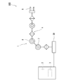
- FIG. 1 is a diagram schematically showing a configuration example of a robot system 100 according to the first embodiment.
- the robot system 100 includes a robot 1, a control unit 2, and a command unit 3.
- the robot 1 is an articulated robot industrial robot (multijoint robot).
- the robot 1 includes a base 30, a robot arm 4, and a hand 5.
- the base 30 is fixed to, for example, a floor and mounted, and supports the robot arm 4 and the hand 5.
- the robot arm 4 has a plurality of joints, and its proximal end is pivotally connected to the base 30.
- the joints of the robot arm 4 are a series of joints extending from the proximal end to the distal end.
- one joint constitutes a first joint 7 (for example, a second axis), and another joint (for example, a third axis) different from the first joint 7 is a second joint 8 Configure
- the first joint 7 and the second joint 8 are configured to be able to be positioned in a posture in which they interfere with each other.
- the posture in which the first joint 7 and the second joint 8 interfere with each other means a posture in which the mutual inertia coefficient of the inertia matrix of the kinetic equation according to equation (1) is large.
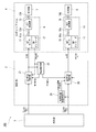
- FIG. 2 is a block diagram schematically showing a configuration example of a control system of the robot system 100 of FIG. In FIG. 2, illustration of joints other than the first joint 7 and the second joint 8 is omitted.
- each joint of the robot arm 4 has a drive unit that drives the joint.
- a reduction gear connected to a joint (rotational shaft) corresponding to an output shaft, and a drive source having an output shaft connected to an input shaft of the reduction gear to rotate the corresponding joint via the reduction gear
- an encoder for detecting the rotation angle of the output shaft of the servomotor.
- the output shaft of the servomotor is connected to the corresponding joint via the reduction gear.
- the encoder also acquires information on the actual operation of the output shaft of the servomotor.
- the encoder detects the angular position of the output shaft of the servomotor, and based on this, detects the actual rotation angle of the output shaft of the servomotor.
- the reduction gear of the second joint 8, that is, the second reduction gear 18 is, for example, a wave gear device (harmonic drive (registered trademark)).
- the reduction gear of the first joint 7 is, for example, a reduction gear having a smaller angle transmission error than the wave gear device.
- the servomotor, the reduction gear, and the encoder for driving the first joint 7 are referred to as a first motor 11, a first reduction gear 13, and a first encoder (first detection unit) 12, respectively.
- the first joint drive unit 9 is configured.
- a servomotor, a reduction gear, and an encoder for driving the second joint 8 are respectively referred to as a second motor 16, a second reduction gear 18, and a second encoder (second detection unit) 17, and these are driven by the second joint.
- the unit 10 is configured.
- the rotation angle means an angular position, but is not limited thereto. It may be a time derivative of angular position, that is, angular velocity or angular acceleration.
- the wave gear device includes a circular spline, a flex spline, and a wave generator.
- the circular spline is a rigid internal gear, and is provided integrally with the housing, for example.
- the flexspline is a flexible external gear and meshes with the circular spline.
- the flexspline has a smaller number of teeth than the circular spline and is connected to the output shaft 18b.
- the wave generator is an elliptical cam that contacts the inside of the flexspline, and is connected to the input shaft 18a.
- the wave gear device has characteristics suitable for a reduction gear of a robot drive mechanism because of its features such as small size, light weight, high reduction ratio, high torque capacity, and non backlash.
- the hand 5 is configured to be able to perform a predetermined operation such as holding an article, and is attached to the tip of the robot arm 4.
- control unit 2 controls each joint and includes, for example, an arithmetic unit such as a microcontroller, a programmable logic device (PLD) such as a CPU, an ASIC, or an FPGA.
- the computing unit may be configured of a single computing unit that performs centralized control, or may be configured of a plurality of computing units that perform distributed control in cooperation with each other.
- Control unit 2 includes a first joint control unit 21, a second joint control unit 26, an error estimation unit 22, and an angle transmission error estimation unit 28.
- the first joint control unit 21, the second joint control unit 26, the error estimation unit 22, and the angle transmission error estimation unit 28 are functional blocks that are realized by execution of a predetermined control program by an operation unit (not shown).
- the control part 2 is comprised by the calculating part separate from the command part 3, it may be integral.
- the first joint control unit 21 is a PI controller (proportional integral controller), and receives a first target rotation angle (first operation target) ⁇ t1 with respect to the first motor 11 input from the command unit 3 (upper device); The first current value supplied to the first motor 11 is calculated based on the deviation from the actual rotation angle ⁇ 1 of the output shaft 11 a of the first motor 11 detected by the first encoder 12. Then, current is supplied to the first motor 11 based on the first current value to control the rotation angle of the output shaft 11 a of the first motor 11.
- PI controller proportional integral controller
- the first joint control unit 21 performs control to bring the deviation between the first target rotation angle ⁇ t1 and the actual rotation angle ⁇ 1 closer to 0 and bring the rotation angle of the output shaft 11a of the first motor 11 closer to the first target rotation angle ⁇ t1. Feedback control of the first motor 11 is performed.
- the first joint control unit 21 compensates for the angular error of the first joint 7 caused by the bending and / or twisting of the robot arm 4 estimated by the error estimating unit 22.
- a first current value is calculated to control the rotation angle of the output shaft 11a of the first motor 11 (details will be described later).
- the second joint control unit 26 is a PI controller, and receives a second target rotation angle (second operation target) ⁇ t 2 with respect to the second motor 16 input from the command unit 3 and a second motor detected by the second encoder 17
- the second current value supplied to the second motor 16 is calculated based on the deviation from the actual rotation angle ⁇ 2 of the sixteen output shafts 16a.
- a current is supplied to the second motor 16 based on the second current value to control the rotation angle of the output shaft 16 a of the second motor 16. That is, the second joint control unit 26 performs control to bring the deviation between the second target rotation angle ⁇ t2 and the actual rotation angle ⁇ 2 closer to 0 and bring the rotation angle of the output shaft 16a of the second motor 16 closer to the second target rotation angle ⁇ t2. Feedback control of the second motor 16 based on
- the second joint control unit 26 compensates for the angular error of the second joint 8 caused by the bending and / or twisting of the robot arm 4 estimated by the error estimating unit 22.
- a second current value is calculated to control the rotation angle of the output shaft 16a of the second motor 16 (details will be described later).
- the second joint control unit 26 estimates the rotation angle of the output shaft 16 a of the second motor 16 estimated by the angle transmission error estimation unit 28 and the output shaft 18 b of the second reduction gear 18.
- the second current value is calculated so as to control the rotation angle of the output shaft 16a of the second motor 16 by compensating for an angle transmission error between the second current value and the rotation angle (details will be described later).
- the error estimating unit 22 determines a first joint resulting from the bending and / or twisting of the robot arm 4 based on the first current value supplied to the first motor 11 and the actual rotation angle ⁇ 1 of the output shaft 11 a of the first motor 11.
- the angular error (error of movement) of the seventh and second joints 8 is estimated.
- a first correction amount for correcting the first current value is calculated based on the estimated angle error of the first joint 7.
- a second correction amount for correcting the second current value is calculated based on the estimated angle error of the second joint 8.
- the error estimation unit 22 receives the first current value and the actual rotation angle ⁇ 1 of the output shaft 11a of the first motor 11 as input, and causes the first joint 7 and the second joint 7 resulting from the bending and / or twisting of the robot arm 4 Using a model that outputs the angular error of the joint 8, the angular error of the first joint 7 and the second joint 8 caused by the deflection and / or twisting of the robot arm 4 is calculated.
- the first motor 11 is based on the first current value due to the deflection and / or twist of the robot arm 4.
- a deviation occurs between the theoretical rotation angle of the output shaft 11a of the first motor 11 obtained from the torque of the output shaft 11a when the current is supplied and the actual rotation angle ⁇ 1 of the output shaft 11a of the first motor 11 .
- the first joint 7 and the second joint 8 resulting from the bending and / or twisting of the robot arm 4 with the first current value and the actual rotation angle ⁇ 1 of the output shaft 11a of the first motor 11 as inputs.
- the error estimating unit 22 predefines a model that outputs the angular error of the first motor 11 and the robot arm 4 based on the first current value and the actual rotation angle ⁇ 1 of the output shaft 11a of the first motor 11 using the model.
- the angular error of the first joint 7 and the second joint 8 due to the deflection and / or the twisting of the second joint 8 is calculated.
- the model measures, for example, the relationship between the first current value, the actual rotation angle ⁇ 1 of the output shaft 11a of the first motor 11, and the angular error of the first joint 7 and the second joint 8 in advance. From the first current value and the actual rotation angle ⁇ 1 of the output shaft 11a of the first motor 11 may be input to construct a model for estimating the angle error of the first joint 7 and the angle error of the second joint 8 .
- the angular error of the first joint 7 and the second joint 8 may be analytically calculated using a dynamic model that estimates the angular error and the angular error of the second joint 8.
- the error estimating unit 22 calculates a first correction amount for compensating the estimated angle error of the first joint 7 and a second correction amount for compensating the angle error of the second joint 8.
- the first correction amount and the second correction amount are input to the first joint control unit 21 and the second joint control unit 26, respectively.
- the first joint control unit 21 calculates the first correction amount By adding, the first current value is calculated in which the angular error of the first joint 7 estimated by the error estimation unit 22 is compensated.
- the second joint control unit 26 calculates the second correction value in the process of calculating the second current value based on the deviation between the second target rotation angle ⁇ t2 and the actual rotation angle ⁇ 2 of the output shaft 16a of the second motor 16. By adding, the second current value is calculated in which the angular error of the second joint 8 estimated by the error estimating unit 22 is compensated.
- the error estimation unit 22 is configured to reduce the natural frequency 1 among the plurality of natural frequencies of the coupled vibration of the system including the first joint 7 and the second joint 8 due to the deflection and / or twisting of the robot arm 4
- the angular error of the second joint 8 is estimated based on the eigen value corresponding to the natural frequency of.
- the angular error of the second joint 8 is estimated based on the eigen value corresponding to one smaller natural frequency of the two natural frequencies.
- the vibration of the first joint 7 and the second joint 8 is expressed as coupled vibration with two degrees of freedom, and is expressed as superposition of two natural vibration modes.
- the mode corresponding to the natural frequency of 1 having a low natural frequency is a first mode in which the first joint 7 and the second joint 8 swing in the same rotational direction
- the other mode is a second mode in which the first joint 7 and the second joint 8 swing in opposite rotational directions.
- estimation is made for both vibration modes. I can not do it.
- the trajectory accuracy of the working end (hand 5) of the robot arm 4 is effectively estimated by estimating the angular error of the second joint 8 based on the natural frequency 1 having a small natural frequency among a plurality of natural frequencies of Can be improved.
- the angle transmission error estimation unit 28 estimates an angle transmission error between the rotation angle of the output shaft 16 a of the second motor 16 and the rotation angle of the output shaft 18 b of the second reduction gear 18.
- the angle transmission error estimating unit 28 calculates the second motor 16 which is the input rotation angle to the second reduction gear 18.
- the angle transmission error between the rotation angle of the output shaft 16a of the second reduction gear 18 and the rotation angle of the output shaft 18b of the second reduction gear 18, which is the output rotation angle of the second reduction gear 18, is estimated.
- the angle transmission error estimation unit 28 calculates a correction amount to be added to the output shaft 16 a of the second motor 16 in order to compensate the angle transmission error (to cancel the angle transmission error).
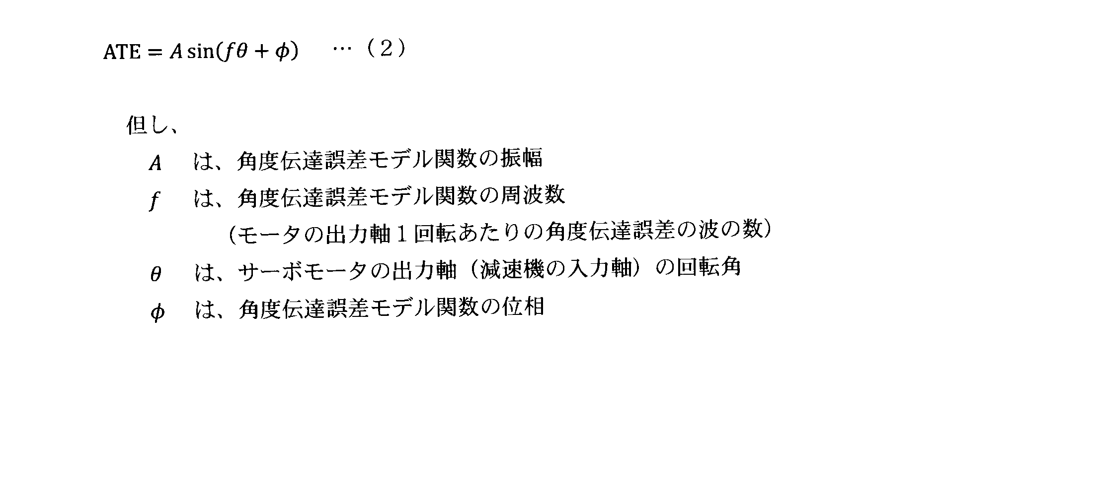
- the frequency f is a component related to 2 that particularly affects the angle transmission error of the wave gear device. Therefore, the frequency f of the second reduction gear 18 configured by the wave gear device is defined as 2, and the correction amount is calculated based on the above equation (1) using the separately identified amplitude A and phase ⁇ corresponding to the frequency f. It may be calculated.
- the angle transmission error estimation unit 28 estimates the angle transmission error based on the second target rotation angle ⁇ t2, and calculates a correction amount for compensating the angle error transmission error of the second joint 8.
- the second joint control unit 26 calculates an angle transmission error estimation unit
- the angle error of the second joint 8 estimated by the error estimating unit 22 and the angle transmission error estimating unit 28 are estimated by adding the correction amount for compensating the angle transmission error of the second joint 8 estimated by 28.
- a second current value that compensates for the angle transmission error of the second joint 8 is calculated.
- the second joint control unit 26 compensates for the angle transmission error by feedforward control.
- the angle transmission error estimation unit 28 adds the correction amount for compensating the angle transmission error of the second joint 8
- the change of the second current value is a change due to the compensation of the angle transmission error.
- a change due to the bending and / or twisting of the robot arm 4 are combined.
- a compensation component of the angular transmission error included in the second current value and the robot arm 4 There is a possibility that an error may occur in the estimation of the angular error of the second joint 8 because it can not be determined from the component related to the change of the second current value due to the bending and / or the twisting.
- the error estimation unit 22 is a joint different from the second joint 8 and is based on the first current value of the first joint 7 not including the compensation component of the angle transmission error. Since it is configured to estimate the angular error, the compensation of the angular transmission error with respect to the second joint 8 interferes with the estimation of the angular error of the second joint 8 due to the deflection and / or twisting of the robot arm 4 It is possible to prevent an error in the estimation of the angular error of the joint 8 and a failure to suppress the vibration of the robot arm 4.
- the compensation of the angle transmission error of the second joint 8 and the compensation of the angular error due to the deflection and / or twisting of the robot arm 4 can be used in combination, and the trajectory accuracy of the robot arm 4 is further improved.
- compensation of the angle transmission error of the second joint 8 is performed by feed forward control, and compensation of the angle error of the second joint 8 caused by the deflection and / or twist of the robot arm 4 is performed by feedback control. It is configured to be
- the command unit 3 generates and outputs a position command for each joint, that is, a target rotation angle of each joint based on the operation program.
- the target rotation angle of each joint includes a first target rotation angle ⁇ t1 for the first motor 11 and a second target rotation angle ⁇ t2 for the second motor 16.
- the output target rotation angle is input to the joint control unit including the first joint control unit 21 and the second joint control unit 26.
- the error estimating unit 22 estimates the angle error of the joint due to the bending and / or twisting of the robot arm 4, and the first joint control unit 21 and the second joint control unit 26. Since the current value which compensated the angle error is calculated, the trajectory accuracy of the working end of the robot arm 4 can be improved.
- the second joint 8 is obtained from the first current value to the first motor 11 included in the first joint 7 by the error estimation unit 22 and the actual rotation angle ⁇ 1 of the output shaft 11a of the first motor 11.
- Calculation of the angular error of the second joint 8 prevents the compensation of the angular transmission error with respect to the second joint 8 from interfering with the estimation of the angular error of the second joint 8 due to the deflection and / or twisting of the robot arm 4
- the compensation of the angular transmission error of the second joint 8 and the compensation of the angular error due to the deflection and / or twisting of the robot arm 4 can be used together, and the trajectory accuracy of the robot arm 4 can be further improved. .
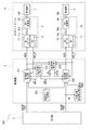
- FIG. 4 is a block diagram schematically showing a configuration example of a control system of the robot system 200 according to the second embodiment.
- the control unit 2 of the robot system 100 includes a first joint control unit 21, a second joint control unit 26, and an error estimation unit 22.
- the robot system 200 includes the first joint control unit 221, the second joint control unit 226, the first error estimation unit 222, the second error estimation unit 229, and the operation mode switching unit 230.
- the first error estimation unit 222 is configured in the same manner as the error estimation unit 22 according to the first embodiment, and thus the detailed description thereof is omitted.
- the second error estimation unit 229 generates a second error caused by the deflection and / or twist of the robot arm 4 based on the first current value supplied to the first motor 11 and the actual rotation angle ⁇ 1 of the output shaft 11 a of the first motor 11.
- the angular error of one joint 7 is estimated.
- a third correction amount for correcting the first current value is calculated based on the estimated angle error of the first joint 7.
- the second error estimating unit 229 is configured to calculate a second joint resulting from the bending and / or twisting of the robot arm 4 based on the second current value supplied to the second motor 16 and the actual rotation angle ⁇ 2 of the second motor 16. Estimate an angular error of 8.
- a fourth correction amount for correcting the second current value is calculated based on the estimated angle error of the second joint 8.
- the third correction amount and the fourth correction amount are input to the first joint control unit 221 and the second joint control unit 226, respectively.
- the operation mode switching unit 230 generates a switching instruction for the first mode and the second mode described later, and the generated switching instruction is input to the first joint control unit 221 and the second joint control unit 226.
- the first joint control unit 221 has a first mode and a second mode.
- the first joint control unit 221 compensates for the angular error of the first joint 7 estimated by the first error estimation unit 222 in the first mode to control the rotation angle of the output shaft 11 a of the first motor 11. 1 Calculate the current value. That is, in the process of calculating the first current value based on the deviation between the first target rotation angle ⁇ t1 and the actual rotation angle ⁇ 1 of the output shaft 11a of the first motor 11 in the first mode, the first joint control unit 221 By adding the first correction amount, a first current value is calculated in which the angular error of the first joint 7 estimated by the first error estimation unit 222 is compensated.
- the first joint control unit 221 controls the rotation angle of the output shaft 11 a of the first motor 11 by compensating for the angular error of the first joint 7 estimated by the second error estimation unit 229 in the second mode.
- the first joint control unit 221 By adding the third correction amount, a first current value is calculated in which the angular error of the first joint 7 estimated by the second error estimation unit 229 is compensated.
- the second joint control unit 226 has two operation modes of a first mode and a second mode.
- the first mode the second joint control unit 226 compensates for the angle transmission error and the angular error of the second joint 8 estimated by the first error estimation unit 222 to obtain the rotation angle of the output shaft 16 a of the second motor 16.
- the second current value is calculated to be controlled.
- the second joint control unit 226 By adding the correction amount of the angle transmission error and the second correction amount, a second current value is calculated in which the angle transmission error and the angle error of the second joint 8 estimated by the first error estimation unit 222 are compensated.
- the second joint control unit 226 also controls the rotation angle of the output shaft 16a of the second motor 16 by compensating for the angular error of the second joint 8 estimated by the second error estimation unit 229 in the second mode. To calculate the second current value.
- the second joint control unit 226 By adding the fourth correction amount, a second current value is calculated in which the angular error of the second joint 8 estimated by the second error estimation unit 229 is compensated.
- the first mode is a mode in which processing similar to the operation processing of the error estimation unit 22 in the first embodiment is performed, and compensation of the angle transmission error and the first error estimation unit 222 A mode in which the operation of the second motor 16 is controlled by calculating the second current value so as to control the rotation angle of the output shaft 16a of the second motor 16 by performing compensation of the calculated angle error of the second joint 8 It is.
- the compensation of the angular error of the second joint 8 calculated by the second error estimation unit 229 is performed without compensation of the angle transmission error, and the compensation of the output shaft 16a of the second motor 16 is performed.
- the second current value is calculated to control the rotation angle, and the operation of the second motor 16 is controlled.
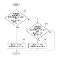
- FIG. 5 is a flowchart showing an operation example of the operation mode switching unit 230.
- the operation mode switching unit 230 instructs the first joint control unit 221 and the second joint control unit 226 to switch between the first mode and the second mode.
- the operation mode switching unit 230 is configured to switch to the first mode when the operation speed of the work end (hand 5) of the robot arm 4 becomes equal to or less than a predetermined speed.
- operation mode switching unit 230 has a state in which the operation speed of the working end of robot arm 4 is slower than a predetermined speed, and the second mode is selected as the operation mode It is determined whether or not (step S11).
- step S11 determines that the operation speed of the work end of robot arm 4 is slower than the predetermined speed and the second mode is selected as the operation mode (Yes in step S11).
- the switching command to switch the operation mode to the first mode is generated (step S12). Then, the operation mode switching unit 230 ends the process. Thereby, not only the compensation of the angular error due to the deflection and / or the twist of the robot arm 4 but also the compensation of the angular transmission error can be used together when performing the required work such as the arc welding etc. , The trajectory accuracy can be improved.
- operation mode switching unit 230 determines whether or not the operation speed of the work end of robot arm 4 is faster than a predetermined speed and that the first mode is selected as the operation mode (step S13).
- operation mode switching unit 230 determines that the operation speed of the work end of robot arm 4 is faster than the predetermined speed and the first mode is selected as the operation mode (Yes in step S13)
- the switching command to switch the operation mode to the second mode is generated (step S13).
- the operation mode switching unit 230 ends the process. In this way, robustness can be enhanced when performing quick work in which the decrease in trajectory accuracy due to the angle transmission error does not become a problem.
- operation mode switching unit 230 determines that the operation speed of the work end of robot arm 4 is slower than the predetermined speed or the second mode is selected as the operation mode (No in step S13), End the process. Then, the operation mode switching unit 230 repeatedly executes the above process at a predetermined cycle time.
- the other configuration is the same as that of the first embodiment, and thus the detailed description thereof is omitted.
Abstract
上位装置から入力された第1モータ(11)に対する第1動作目標及び第1モータの出力軸(11a)の実動作との偏差に基づき第1モータに供給する第1電流値を算出し、且つ第1電流値に基づき第1モータに電流を供給し第1モータの出力軸の動作を制御する第1関節制御部(21)と、上位装置から入力された第2モータ(16)に対する第2動作目標及び第2モータの出力軸(16a)の実動作との偏差に基づき第2モータに供給する第2電流値を算出し、且つ第2電流値に基づき第2モータに電流を供給し第2モータの出力軸の動作を制御する第2関節制御部(26)と、第1電流値及び第1モータの出力軸の実動作に基づいてロボットアーム(4)の撓み及び/又は捩れに起因する第2関節(8)の動作の誤差を推定する誤差推定部(27)と、を備え、第2関節制御部は、第2関節の角度誤差を補償して第2モータの出力軸の回転角を制御するように第2電流値を算出する。
Description
本発明は、ロボットシステム及びロボットシステムの制御方法に関する。
従来からロボットアーム先端の振動抑制効果を高めることができるロボット制御装置が知られている(例えば特許文献1参照)。
このロボット制御装置は、弾性機構を有するロボットアームを制御対象とし、モータの角速度を比例積分制御してモータへ電流指令値を出力する角速度制御系を有し、ロボットアームの非線形動力学モデルを有し、モータの角度速度と電流指令値を入力とし、軸ねじり角速度、リンクの角加速度を推定するオブザーバと、オブザーバによって推定されたリンクの角速度とモータの角速度との差から軸ねじり角速度を算出し、角速度制御系にフィードバックする状態フィードバック部を有する。
しかし、特許文献1に記載のロボット制御装置は、推定対象関節に含まれるモータの角度速度とモータに対する電流指令値に基づいて、推定対象関節の軸ねじり角速度を推定しているため、モータに対する電流指令値に他の補償要素が含まれているときは、軸ねじり角速度を推定できない場合があった。
上記課題を解決するため、本発明のある態様に係るロボットシステムは、第1関節及び第2関節を含む複数の関節を含むロボットアームと、出力軸が前記第1関節に接続され、前記第1関節を回動させる第1モータを有する第1関節駆動部と、前記第1モータの前記出力軸の実動作の情報を取得する第1検知部と、上位装置から入力された前記第1モータに対する第1動作目標及び前記第1モータの前記出力軸の前記実動作との偏差に基づき前記第1モータに供給する第1電流値を算出し、且つ該第1電流値に基づき前記第1モータに電流を供給し前記第1モータの前記出力軸の動作を制御する第1関節制御部と、出力軸が前記第2関節に接続され、前記第2関節を回動させる第2モータを有する第2関節駆動部と、前記第2モータの前記出力軸の実動作の情報を取得する第2検知部と、前記上位装置から入力された前記第2モータに対する第2動作目標及び前記第2モータの前記出力軸の前記実動作との偏差に基づき前記第2モータに供給する第2電流値を算出し、且つ該第2電流値に基づき前記第2モータに電流を供給し前記第2モータの前記出力軸の動作を制御する第2関節制御部と、前記第1電流値及び前記第1モータの前記出力軸の前記実動作に基づいて前記ロボットアームの撓み及び/又は捩れに起因する前記第2関節の動作の誤差を推定する誤差推定部と、を備え、前記第2関節制御部は、前記ロボットアームの撓み及び/又は捩れに起因する前記第2関節の動作の誤差を補償して前記第2モータの前記出力軸の動作を制御するように前記第2電流値を算出する。
この構成によれば、ロボットアームの撓み及び/又は捩れに起因する第2関節の動作の誤差の補償を行う制御が、他の制御と干渉することを防ぐことができる。これによって、ロボットアームの振動を効果的に抑制することができ、ロボットアームの作業端の軌跡精度を向上させることができる。
本発明は、ロボットアームの作業端の軌跡精度を向上させることという効果を奏する。
ある態様に係るロボットシステムは、第1関節及び第2関節を含む複数の関節を含むロボットアームと、出力軸が前記第1関節に接続され、前記第1関節を回動させる第1モータを有する第1関節駆動部と、前記第1モータの前記出力軸の実動作の情報を取得する第1検知部と、上位装置から入力された前記第1モータに対する第1動作目標及び前記第1モータの前記出力軸の前記実動作との偏差に基づき前記第1モータに供給する第1電流値を算出し、且つ該第1電流値に基づき前記第1モータに電流を供給し前記第1モータの前記出力軸の動作を制御する第1関節制御部と、出力軸が前記第2関節に接続され、前記第2関節を回動させる第2モータを有する第2関節駆動部と、前記第2モータの前記出力軸の実動作の情報を取得する第2検知部と、前記上位装置から入力された前記第2モータに対する第2動作目標及び前記第2モータの前記出力軸の前記実動作との偏差に基づき前記第2モータに供給する第2電流値を算出し、且つ該第2電流値に基づき前記第2モータに電流を供給し前記第2モータの前記出力軸の動作を制御する第2関節制御部と、前記第1電流値及び前記第1モータの前記出力軸の前記実動作に基づいて前記ロボットアームの撓み及び/又は捩れに起因する前記第2関節の動作の誤差を推定する誤差推定部と、を備え、前記第2関節制御部は、前記ロボットアームの撓み及び/又は捩れに起因する前記第2関節の動作の誤差を補償して前記第2モータの前記出力軸の動作を制御するように前記第2電流値を算出する。
この構成によれば、ロボットアームの撓み及び/又は捩れに起因する第2関節の動作の誤差の補償を行う制御が、他の制御と干渉することを防ぐことができる。これによって、ロボットアームの振動を効果的に抑制することができ、ロボットアームの作業端の軌跡精度を向上させることができる。
前記第1検知部が取得する前記実動作の情報は、前記第1モータの前記出力軸の角度位置、角速度、角加速度の少なくとも何れかであり、前記第1動作目標は、前記第1モータに対する位置指令、速度指令、加速度指令の少なくとも何れかであり、前記第1動作目標及び前記第1モータの前記出力軸の前記実動作との前記偏差は、位置偏差、速度偏差、加速度偏差の少なくとも何れかであり、前記第2検知部が取得する前記実動作の情報は、前記第2モータの前記出力軸の角度位置、角速度、角加速度の少なくとも何れかであり、前記第2動作目標は、前記第2モータに対する位置指令、速度指令、加速度指令の少なくとも何れかであり、前記第2動作目標及び前記第2モータの前記出力軸の前記実動作との前記偏差は、位置偏差、速度偏差、加速度偏差の少なくとも何れかであり、前記ロボットアームの撓み及び/又は捩れに起因する前記第2関節の動作の誤差は、角度誤差、角度速度誤差、角加速度誤差の少なくとも何れかであってもよい。
この構成によれば、ロボットアームの撓み及び/又は捩れに起因する第2関節の動作の誤差を適切に補償することができる。
前記誤差推定部は、前記ロボットアームの撓み及び/又は捩れに起因する前記第1関節及び前記第2関節を含む系の連成振動の複数の固有振動数のうち固有振動数が小さい1の固有振動数に基づいて前記ロボットアームの撓み及び/又は捩れに起因する前記第2関節の動作の誤差を推定してもよい。
この構成によれば、ロボットアームの撓み及び/又は捩れに起因するロボットアームの振動を適切に抑制することができる。
前記第2関節駆動部は、入力軸が前記第2モータの前記出力軸に接続され且つ出力軸が前記第2関節に接続された減速機を更に含み、前記第2モータが該減速機を介して前記第2関節を回動させ、前記第2モータの前記出力軸の回転角と前記減速機の前記出力軸の回転角との間の角度伝達誤差を推定する角度伝達誤差推定部を更に備え、前記第2関節制御部は、前記角度伝達誤差と前記ロボットアームの撓み及び/又は捩れに起因する前記第2関節の動作の誤差とを補償して前記第2モータの前記出力軸の動作を制御するように前記第2電流値を算出してもよい。
この構成によれば、角度伝達誤差補償と、ロボットアームの撓み及び/又は捩れに起因する動作の誤差の補償との干渉を防止することができる。これによって、両補償を併用することができ、ロボットアームの振動を効果的に抑制することができる。
前記誤差推定部は、前記第1電流値及び前記第1モータの前記出力軸の前記実動作に基づいて前記ロボットアームの撓み及び/又は捩れに起因する前記第2関節の動作の誤差を推定する第1誤差推定部と、前記第2電流値及び前記第2モータの前記出力軸の前記実動作に基づいて前記ロボットアームの撓み及び/又は捩れに起因する前記第2関節の動作の誤差を推定する第2誤差推定部とを有し、前記第2関節制御部は前記角度伝達誤差と前記第1誤差推定部が推定した前記ロボットアームの撓み及び/又は捩れに起因する前記第2関節の動作の誤差とを補償して前記第2モータの前記出力軸の動作を制御するように前記第2電流値を算出する第1モードと、前記第2誤差推定部が推定した前記ロボットアームの撓み及び/又は捩れに起因する前記第2関節の動作の誤差を補償して前記第2モータの前記出力軸の動作を制御するように前記第2電流値を算出する第2モードとを有し、前記第2関節制御部に指示して前記第1モードと前記第2モードとを切り替える動作モード切替部を更に有していてもよい。
この構成によれば、条件に応じて適切にモードを切り替えることにより、ロボットアームの振動を適切に抑制することができる。
前記動作モード切替部は、前記ロボットアームの作業端の動作速度が所定の速度以下になると前記第1モードに切り替えてもよい。
この構成によれば、精度の要求される作業を実行するときに角度伝達誤差の影響を低減することができる。
ある態様に係るロボットシステムの制御方法は、第1関節及び第2関節を含む複数の関節を含むロボットアームと、出力軸が前記第1関節に接続され、前記第1関節を回動させる第1モータを有する第1関節駆動部と、前記第1モータの前記出力軸の実動作の情報を取得する第1検知部と、前記第1モータの前記出力軸の動作を制御する第1関節制御部と、出力軸が前記第2関節に接続され、前記第2関節を回動させる第2モータを有する第2関節駆動部と、前記第2モータの前記出力軸の実回転角を検出するための事象を検知する第2検知部と、前記第2モータの前記出力軸の動作を制御する第2関節制御部と、を備えるロボットシステムの制御方法であって、上位装置から入力された前記第1モータに対する第1動作目標と前記第1モータの前記出力軸の前記実動作との偏差に基づき前記第1モータに供給する第1電流値を算出するステップと、前記第1電流値及び前記第1モータの前記出力軸の前記実動作に基づいて前記ロボットアームの撓み及び/又は捩れに起因する前記第2関節の動作の誤差を推定するステップと、前記上位装置から入力された前記第2モータに対する第2動作目標及び前記第2モータの前記出力軸の前記実動作との偏差に基づき前記第2モータに供給する第2電流値を算出し、且つ前記第2関節の動作の誤差を補償して前記第2モータの前記出力軸の回転角を制御するように前記第2電流値を算出するステップと、前記第2電流値に基づき前記第2モータに電流を供給するステップと、を有する。
この構成によれば、ロボットアームの撓み及び/又は捩れに起因する第2関節の動作の誤差の補償を行う制御が、他の制御と干渉することを防ぐことができる。これによって、ロボットアームの振動を効果的に抑制することができ、ロボットアームの作業端の軌跡精度を向上させることができる。
以下、実施の形態について、図面を参照しながら説明する。なお、以下の実施の形態によって本発明が限定されるものではない。また、以下では、全ての図を通じて、同一又は相当する要素には同一の参照符号を付して、その重複する説明を省略する。
(実施の形態1)
図1は、実施の形態1に係るロボットシステム100の構成例を概略的に示す図である。
図1は、実施の形態1に係るロボットシステム100の構成例を概略的に示す図である。
図1に示すように、ロボットシステム100は、ロボット1と、制御部2と、指令部3とを備える。
[ロボットの構成例]
ロボット1は、多関節型ロボットの産業用ロボット(多関節ロボット)である。
ロボット1は、多関節型ロボットの産業用ロボット(多関節ロボット)である。
ロボット1は、基部30と、ロボットアーム4と、ハンド5とを含む。基部30は、例えば床面に固定されて載置され、ロボットアーム4及びハンド5を支持している。
ロボットアーム4は、複数の関節を有し、基端部が基部30に対して回動可能に連結されている。ロボットアーム4の関節は、複数の関節が基端部から先端部に向かって一列に連なっている。ロボットアーム4の複数の関節のうち、1の関節が第1関節7(例えば第2軸)を構成し、第1関節7と異なる別の1の関節(例えば第3軸)が第2関節8を構成する。第1関節7と第2関節8とは、互いに干渉する姿勢に位置させることができるように構成されている。第1関節7と第2関節8とが互いに干渉する姿勢とは、式(1)に係る動力学方程式の慣性行列の相互慣性係数が大きい姿勢をいう。

図2に示すように、ロボットアーム4の各関節は、関節を駆動する駆動部を有する。各駆動部は、出力軸が対応する関節(回動軸)に接続された減速機と、出力軸が減速機の入力軸に接続され、減速機を介して対応する関節を回動させる駆動源であるサーボモータと、サーボモータの出力軸の回転角を検知するエンコーダとを有する。このように、サーボモータの出力軸は、減速機を介して対応する関節に接続されている。また、エンコーダは、サーボモータの出力軸の実動作の情報を取得する。本実施の形態においては、エンコーダはサーボモータの出力軸の角度位置を検知し、これに基づいて、サーボモータの出力軸の実回転角を検出する。本実施の形態において、第2関節8の減速機、すなわち第2減速機18は、例えば波動歯車装置(ハーモニックドライブ(登録商標))である。また、第1関節7の減速機は、例えば波動歯車装置に比べて角度伝達誤差が少ない減速機である。
以下、説明の便宜上、第1関節7を駆動するサーボモータ、減速機、及びエンコーダをそれぞれ第1モータ11、第1減速機13、及び第1エンコーダ(第1検知部)12といい、これらが第1関節駆動部9を構成する。また、第2関節8を駆動するサーボモータ、減速機、及びエンコーダをそれぞれ第2モータ16、第2減速機18、及び第2エンコーダ(第2検知部)17といい、これらが第2関節駆動部10を構成する。なお、本実施の形態において回転角とは、角度位置を意味するがこれに限定されない。角度位置の時間微分値、すなわち角速度や、角加速度であってももよい。
第2減速機18に係る波動歯車装置は、サーキュラスプラインと、フレクスプラインと、ウェーブジェネレータとを備える。サーキュラスプラインは、剛性の内歯歯車であり、例えば筐体と一体的に設けられる。フレクスプラインは、可撓性を有する外歯歯車であり、サーキュラスプラインと歯合する。フレクスプラインは、サーキュラスプラインよりも歯数が少なく、出力軸18bと接続される。ウェーブジェネレータは、フレクスプラインの内側に接触する楕円状のカムであり、入力軸18aと接続されている。そして、入力軸を回転させることによって、ウェーブジェネレータがフレクスプラインとサーキュラスプラインとの噛み合い位置を移動させ、サーキュラスプラインとフレクスプラインの歯数差に応じてフレクスプラインが回転軸周りに回転し、出力軸が回転する。波動歯車装置は、小型・軽量、高減速比、高トルク容量、ノンバックラッシ等の特徴からロボットの駆動機構の減速機に適した特性を有する。
ところで、図3に示すように、波動歯車装置などの減速機には、加工誤差等により、減速機に入力される入力回転角に減速比を乗じた理論上の出力回転角と、実際の出力回転角との差である角度伝達誤差が生じる。この角度伝達誤差は、入力軸の回転に伴って周期的な変化として表れる。このような減速機出力軸の角度伝達誤差ATEは、以下の式(2)に係る関数を用いたモデルによって近似的に表現することが可能である。
[制御部の構成例]
図2に示すように、制御部2は、各関節を制御し、例えばマイクロコントローラ、CPU、ASIC、FPGA等のプログラマブルロジックデバイス(PLD)などの演算器を含む。演算器は、集中制御する単独の演算器で構成されていてもよく、互いに協働して分散制御する複数の演算器で構成されてもよい。制御部2は、第1関節制御部21と、第2関節制御部26と、誤差推定部22と、角度伝達誤差推定部28とを含む。第1関節制御部21、第2関節制御部26、誤差推定部22、及び角度伝達誤差推定部28は、所定の制御プログラムを図示しない演算部が実行することにより実現される機能ブロックである。なお、制御部2は、指令部3と別体の演算器で構成されているが、一体であってもよい。
図2に示すように、制御部2は、各関節を制御し、例えばマイクロコントローラ、CPU、ASIC、FPGA等のプログラマブルロジックデバイス(PLD)などの演算器を含む。演算器は、集中制御する単独の演算器で構成されていてもよく、互いに協働して分散制御する複数の演算器で構成されてもよい。制御部2は、第1関節制御部21と、第2関節制御部26と、誤差推定部22と、角度伝達誤差推定部28とを含む。第1関節制御部21、第2関節制御部26、誤差推定部22、及び角度伝達誤差推定部28は、所定の制御プログラムを図示しない演算部が実行することにより実現される機能ブロックである。なお、制御部2は、指令部3と別体の演算器で構成されているが、一体であってもよい。
第1関節制御部21は、PI制御器(比例積分制御器)であり、指令部3(上位装置)から入力された第1モータ11に対する第1目標回転角(第1動作目標)θt1と、第1エンコーダ12が検出した第1モータ11の出力軸11aの実回転角θ1との偏差に基づき、第1モータ11に供給する第1電流値を算出する。そして、第1電流値に基づき第1モータ11に電流を供給し第1モータ11の出力軸11aの回転角を制御する。すなわち、第1関節制御部21は、第1目標回転角θt1と実回転角θ1との偏差を0に近づけ、第1モータ11の出力軸11aの回転角を第1目標回転角θt1に近づける制御を基本とする第1モータ11のフィードバック制御を行う。
また、第1関節制御部21は、第1電流値を算出する過程において、誤差推定部22が推定したロボットアーム4の撓み及び/又は捩れに起因する第1関節7の角度誤差を補償して第1モータ11の出力軸11aの回転角を制御するように第1電流値を算出する(詳細は後述)。
第2関節制御部26は、PI制御器であり、指令部3から入力された第2モータ16に対する第2目標回転角(第2動作目標)θt2と、第2エンコーダ17が検出した第2モータ16の出力軸16aの実回転角θ2との偏差に基づき、第2モータ16に供給する第2電流値を算出する。そして、第2電流値に基づき第2モータ16に電流を供給し第2モータ16の出力軸16aの回転角を制御する。すなわち、第2関節制御部26は、第2目標回転角θt2と実回転角θ2との偏差を0に近づけ、第2モータ16の出力軸16aの回転角を第2目標回転角θt2に近づける制御を基本とする第2モータ16のフィードバック制御を行う。
また、第2関節制御部26は、第2電流値を算出する過程において、誤差推定部22が推定したロボットアーム4の撓み及び/又は捩れに起因する第2関節8の角度誤差を補償して第2モータ16の出力軸16aの回転角を制御するように第2電流値を算出する(詳細は後述)。
更に、第2関節制御部26は、第2電流値を算出する過程において、角度伝達誤差推定部28が推定した第2モータ16の出力軸16aの回転角と第2減速機18の出力軸18bの回転角との間の角度伝達誤差を補償して第2モータ16の出力軸16aの回転角を制御するように第2電流値を算出する(詳細は後述)。
誤差推定部22は、第1モータ11に供給する第1電流値及び第1モータ11の出力軸11aの実回転角θ1に基づいて、ロボットアーム4の撓み及び/又は捩れに起因する第1関節7及び第2関節8の角度誤差(動作の誤差)を推定する。そして、推定した第1関節7の角度誤差に基づいて第1電流値を補正するための第1補正量を算出する。更に、推定した第2関節8の角度誤差に基づいて第2電流値を補正するための第2補正量を算出する。
すなわち、誤差推定部22は、第1電流値と、第1モータ11の出力軸11aの実回転角θ1を入力として、ロボットアーム4の撓み及び/又は捩れに起因する第1関節7及び第2関節8の角度誤差を出力するモデルを用いて、ロボットアーム4の撓み及び/又は捩れに起因する第1関節7及び第2関節8の角度誤差を算出する。
ところで、ロボットアーム4の動作によって、ロボットアーム4は撓んだり、捩れたりして振動すると、ロボットアーム4の撓み及び/又は捩れに起因して、第1モータ11に第1電流値に基づいて電流を供給したときの出力軸11aのトルクから求められる第1モータ11の出力軸11aの理論上の回転角と、第1モータ11の出力軸11aの実回転角θ1との間に偏差が生じる。したがって、第1電流値、及び第1モータ11の出力軸11aの実回転角θ1に基づいてロボットアーム4の撓み及び/又は捩れを推定することが可能であり、更にはロボットアーム4の撓み及び/又は捩れに起因する各関節の角度誤差の推定が可能である。
本実施の形態において、第1電流値、及び第1モータ11の出力軸11aの実回転角θ1を入力として、ロボットアーム4の撓み及び/又は捩れに起因する第1関節7及び第2関節8の角度誤差を出力するモデルを予め規定し、誤差推定部22は、当該モデルを用いて、第1電流値、及び第1モータ11の出力軸11aの実回転角θ1に基づいて、ロボットアーム4の撓み及び/又は捩れに起因する第1関節7及び第2関節8の角度誤差を算出する。
当該モデルは、たとえば、第1電流値と、第1モータ11の出力軸11aの実回転角θ1と、第1関節7及び第2関節8の角度誤差との関係を予め計測し、この計測値から第1電流値と、第1モータ11の出力軸11aの実回転角θ1とを入力として、第1関節7の角度誤差及び第2関節8の角度誤差を推定するモデルを構築してもよい。また、第1電流値に対応する電流を第1モータ11に供給したときの出力軸11aのトルクと、第1モータ11の出力軸11aの実回転角θ1との関係から、第1関節7の角度誤差及び第2関節8の角度誤差を推定する動力学モデルを用いて解析的に第1関節7及び第2関節8の角度誤差を算出してもよい。
更に、誤差推定部22は、推定した第1関節7の角度誤差を補償するための第1補正量、及び第2関節8の角度誤差を補償するための第2補正量を算出する。第1補正量及び第2補正量は、それぞれ第1関節制御部21及び第2関節制御部26に入力される。
そして、第1関節制御部21は、第1目標回転角θt1と第1モータ11の出力軸11aの実回転角θ1との偏差に基づき第1電流値を算出する過程において、第1補正量を加算することによって、誤差推定部22が推定した第1関節7の角度誤差を補償した第1電流値を算出する。
また、第2関節制御部26は、第2目標回転角θt2と第2モータ16の出力軸16aの実回転角θ2との偏差に基づき第2電流値を算出する過程において、第2補正量を加算することによって、誤差推定部22が推定した第2関節8の角度誤差を補償した第2電流値を算出する。
更に、誤差推定部22は、ロボットアーム4の撓み及び/又は捩れに起因する第1関節7及び第2関節8を含む系の連成振動の複数の固有振動数のうち固有振動数が小さい1の固有振動数に対応する固有値に基づいて第2関節8の角度誤差を推定する。第1関節7及び第2関節8からなる系の場合は2つの固有振動数のうち、小さい一方の固有振動数に対応する固有値に基づいて第2関節8の角度誤差を推定する。
すなわち、第1関節7及び第2関節8の振動は、2自由度の連成振動として表され、2つの固有振動モードの重ね合わせとして表される。2つの固有振動モードの固有振動数のうち、固有振動数が小さい1の固有振動数に対応するモードは、第1関節7及び第2関節8が互いに同じ回転方向に揺れる第1モードであり、他方のモードは、第1関節7及び第2関節8が互いに反対の回転方向に揺れる第2モードである。本実施の形態においては、推定対象関節とは異なる関節(第1関節7)から取得した情報のみから推定対象関節(第2関節8)の振動を推定するため、両方の振動モードについて推定することはできない。そこで、ロボットアーム4の作業端(ハンド5)の軌跡精度の低下に与える影響がより大きい第1モードに対応する固有振動数、すなわち第1関節7及び第2関節8を含む系の連成振動の複数の固有振動数のうち固有振動数が小さい1の固有振動数に基づいて第2関節8の角度誤差を推定することにより、ロボットアーム4の作業端(ハンド5)の軌跡精度を効果的に向上させることができる。
角度伝達誤差推定部28は、第2モータ16の出力軸16aの回転角と第2減速機18の出力軸18bの回転角との間の角度伝達誤差を推定する。
すなわち、角度伝達誤差推定部28は、上記式(2)に係る角度伝達誤差の周期的な変動をモデル化した周期関数に基づいて、第2減速機18に対する入力回転角である第2モータ16の出力軸16aの回転角と第2減速機18の出力回転角である第2減速機18の出力軸18bの回転角との間の角度伝達誤差を推定する。そして、角度伝達誤差推定部28は、角度伝達誤差を補償するため(角度伝達誤差をキャンセルするため)に第2モータ16の出力軸16aに加えるべき補正量を算出する。
例えば、波動歯車装置の角度伝達誤差に特に大きな影響をあたえるのは周波数fが2に係る成分であることが判っている。従って、波動歯車装置で構成した第2減速機18の周波数fを2と規定し、当該周波数fに対応する別途同定した振幅A,位相φを用いて上記式(1)に基づいて補正量を算出してもよい。このように、角度伝達誤差推定部28は、第2目標回転角θt2に基づき角度伝達誤差を推定し、第2関節8の角度誤差伝達誤差を補償するための補正量を算出する。
そして、第2関節制御部26は、第2目標回転角θt2と第2モータ16の出力軸16aの実回転角θ2との偏差に基づき第2電流値を算出する過程において、角度伝達誤差推定部28が推定した第2関節8の角度伝達誤差を補償するための補正量を加算することによって、誤差推定部22が推定した第2関節8の角度誤差、及び角度伝達誤差推定部28が推定した第2関節8の角度伝達誤差を補償した第2電流値を算出する。このように、第2関節制御部26は、フィードフォワード制御によって、角度伝達誤差の補償を行う。
ところで、角度伝達誤差推定部28が第2関節8の角度伝達誤差を補償するための補正量を加算することにより、第2電流値の変化は、角度伝達誤差の補償を行ったことによる変化と、ロボットアーム4の撓み及び/又は捩れに起因する変化とが合成されたものとなる。この第2電流値に基づきロボットアーム4の撓み及び/又は捩れに起因する第2関節8の角度誤差を推定しようとしても、第2電流値に含まれる角度伝達誤差の補償成分と、ロボットアーム4の撓み及び/又は捩れに起因する第2電流値の変化に係る成分とを判別することができず、第2関節8の角度誤差の推定に誤りが生じる場合があった。しかし、本実施の形態において、誤差推定部22は、第2関節8とは異なる関節であって、角度伝達誤差の補償成分を含まない第1関節7の第1電流値に基づき第2関節の角度誤差を推定するよう構成されているので、ロボットアーム4の撓み及び/又は捩れに起因する第2関節8の角度誤差の推定に第2関節8に対する角度伝達誤差の補償が干渉し、第2関節8の角度誤差の推定に誤りが生じ、ロボットアーム4の振動の抑制に失敗することを防止することができる。これによって、第2関節8の角度伝達誤差の補償と、ロボットアーム4の撓み及び/又は捩れに起因する角度誤差の補償とを併用することができ、ロボットアーム4の軌跡精度をより向上させることができる。
このように、第2関節8の角度伝達誤差の補償は、フィードフォワード制御により行われ、ロボットアーム4の撓み及び/又は捩れに起因する第2関節8の角度誤差の補償は、フィードバック制御により行われるように構成されている。
指令部3は、動作プログラムに基づき、各関節に対する位置指令、すなわち各関節の目標回転角を生成し、出力する。各関節の目標回転角には、第1モータ11に対する第1目標回転角θt1、及び第2モータ16に対する第2目標回転角θt2が含まれる。出力された目標回転角は、第1関節制御部21及び第2関節制御部26を含む関節制御部に入力される。
以上に説明したように、ロボットシステム100は、誤差推定部22がロボットアーム4の撓み及び/又は捩れに起因する関節の角度誤差を推定し、第1関節制御部21及び第2関節制御部26が角度誤差を補償した電流値を算出するので、ロボットアーム4の作業端の軌跡精度を向上させることができる。
また、ロボットシステム100は、誤差推定部22が第1関節7に含まれる第1モータ11への第1電流値、及び第1モータ11の出力軸11aの実回転角θ1から、第2関節8の角度誤差を算出するので、ロボットアーム4の撓み及び/又は捩れに起因する第2関節8の角度誤差の推定に第2関節8に対する角度伝達誤差の補償が干渉することを防止することができ、第2関節8の角度伝達誤差の補償と、ロボットアーム4の撓み及び/又は捩れに起因する角度誤差の補償とを併用することができ、ロボットアーム4の軌跡精度をより向上させることができる。
(実施の形態2)
以下では実施の形態2の構成、動作について、実施の形態1との相違点を中心に述べる。
以下では実施の形態2の構成、動作について、実施の形態1との相違点を中心に述べる。
図4は、実施の形態2に係るロボットシステム200の制御系統の構成例を概略的に示すブロック図である。
上記実施の形態1において、ロボットシステム100の制御部2は、第1関節制御部21、第2関節制御部26、及び誤差推定部22を含む。これに対し、本実施の形態において、ロボットシステム200は、第1関節制御部221、第2関節制御部226、第1誤差推定部222、第2誤差推定部229、及び動作モード切替部230を含む。第1誤差推定部222は、上記実施の形態1にかかる誤差推定部22と同様に構成されるので、その詳細な説明を省略する。
第2誤差推定部229は、第1モータ11に供給する第1電流値及び第1モータ11の出力軸11aの実回転角θ1に基づいて、ロボットアーム4の撓み及び/又は捩れに起因する第1関節7の角度誤差を推定する。そして、推定した第1関節7の角度誤差に基づいて第1電流値を補正するための第3補正量を算出する。また、第2誤差推定部229は、第2モータ16に供給する第2電流値及び第2モータ16の実回転角θ2に基づいて、ロボットアーム4の撓み及び/又は捩れに起因する第2関節8の角度誤差を推定する。そして、推定した第2関節8の角度誤差に基づいて第2電流値を補正するための第4補正量を算出する。第3補正量及び第4補正量は、それぞれ第1関節制御部221及び第2関節制御部226に入力される。
動作モード切替部230は、後述する第1モードと第2モードとの切替指令を生成し、生成された切替指令は、第1関節制御部221及び第2関節制御部226に入力される。
そして、第1関節制御部221は、第1モードと第2モードとを有する。第1関節制御部221は、第1モードにおいて、第1誤差推定部222が推定した第1関節7の角度誤差を補償して第1モータ11の出力軸11aの回転角を制御するように第1電流値を算出する。すなわち、第1関節制御部221は、第1モードにおいて、第1目標回転角θt1と第1モータ11の出力軸11aの実回転角θ1との偏差に基づき第1電流値を算出する過程において、第1補正量を加算することによって、第1誤差推定部222が推定した第1関節7の角度誤差を補償した第1電流値を算出する。また、第1関節制御部221は、第2モードにおいて、第2誤差推定部229が推定した第1関節7の角度誤差を補償して第1モータ11の出力軸11aの回転角を制御するように第1電流値を算出する。すなわち、第1関節制御部221は、第2モードにおいて、第1目標回転角θt1と第1モータ11の出力軸11aの実回転角θ1との偏差に基づき第1電流値を算出する過程において、第3補正量を加算することによって、第2誤差推定部229が推定した第1関節7の角度誤差を補償した第1電流値を算出する。
また、第2関節制御部226は、第1モードと第2モードとの二つの動作モードを有する。第2関節制御部226は、第1モードにおいて、角度伝達誤差と第1誤差推定部222が推定した第2関節8の角度誤差とを補償して第2モータ16の出力軸16aの回転角を制御するように第2電流値を算出する。すなわち、第2関節制御部226は、第1モードにおいて、第2目標回転角θt2と第2モータ16の出力軸16aの実回転角θ2との偏差に基づき第2電流値を算出する過程において、角度伝達誤差の補正量及び第2補正量を加算することによって、角度伝達誤差と第1誤差推定部222が推定した第2関節8の角度誤差とを補償した第2電流値を算出する。また、第2関節制御部226は、第2モードにおいて、第2誤差推定部229が推定した第2関節8の角度誤差を補償して第2モータ16の出力軸16aの回転角を制御するように第2電流値を算出する。すなわち、第2関節制御部226は、第2モードにおいて、第2目標回転角θt2と第2モータ16の出力軸16aの実回転角θ2との偏差に基づき第2電流値を算出する過程において、第4補正量を加算することによって、第2誤差推定部229が推定した第2関節8の角度誤差を補償した第2電流値を算出する。
すなわち、第2関節8について、第1モードは、上記実施の形態1における誤差推定部22の動作処理と同様の処理を行うモードであり、角度伝達誤差の補償と、第1誤差推定部222が算出した第2関節8の角度誤差の補償とを行って、第2モータ16の出力軸16aの回転角を制御するように第2電流値を算出し、第2モータ16の動作を制御するモードである。これに対し、第2モードは、角度伝達誤差の補償を行わずに、第2誤差推定部229が算出した第2関節8の角度誤差の補償を行って、第2モータ16の出力軸16aの回転角を制御するように第2電流値を算出し、第2モータ16の動作を制御するモードである。
図5は、動作モード切替部230の動作例を示すフローチャートである。
そして、動作モード切替部230は、第1関節制御部221及び第2関節制御部226に指示して第1モードと第2モードとを切り替える。そして、動作モード切替部230は、ロボットアーム4の作業端(ハンド5)の動作速度が所定の速度以下になると第1モードに切り替えるように構成されている。本実施の形態において、動作モード切替部230は、図5に示すように、ロボットアーム4の作業端の動作速度が所定の速度よりも遅く、且つ動作モードとして第2モードが選択されている状態であるか否かを判定する(ステップS11)。そして、動作モード切替部230が、ロボットアーム4の作業端の動作速度が所定の速度よりも遅く、且つ動作モードとして第2モードが選択されている状態であると判定すると(ステップS11においてYes)、動作モードを第1モードに切り替える切替指令を生成する(ステップS12)。そして、動作モード切替部230は処理を終了させる。これによって、アーク溶接等の精度の要求される作業を実行するときに、ロボットアーム4の撓み及び/又は捩れに起因する角度誤差の補償のみならず、角度伝達誤差の補償も併用することができ、軌跡精度を向上させることができる。
一方、動作モード切替部230がロボットアーム4の作業端の動作速度が所定の速度よりも速い、又は動作モードとして第1モードが選択されている状態であると判定すると(ステップS11においてNo)、次に、動作モード切替部230は、ロボットアーム4の作業端の動作速度が所定の速度よりも速く、且つ動作モードとして第1モードが選択されている状態であるか否かを判定する(ステップS13)。そして、動作モード切替部230が、ロボットアーム4の作業端の動作速度が所定の速度よりも速く、且つ動作モードとして第1モードが選択されている状態であると判定すると(ステップS13においてYes)、動作モードを第2モードに切り替える切替指令を生成する(ステップS13)。そして、動作モード切替部230は処理を終了させる。これによって、角度伝達誤差による軌跡精度の低下が問題とならないような素早い作業を行う際において、ロバスト性を高めることができる。
一方、動作モード切替部230がロボットアーム4の作業端の動作速度が所定の速度よりも遅い、又は動作モードとして第2モードが選択されている状態であると判定すると(ステップS13においてNo)、処理を終了させる。そして、動作モード切替部230は、上記処理を所定のサイクルタイムで繰り返し実行する。その他の構成は、上記実施の形態1と同様であるので、その詳細な説明を省略する。
上記説明から、当業者にとっては、本発明の多くの改良や他の実施形態が明らかである。従って、上記説明は、例示としてのみ解釈されるべきであり、本発明を実行する最良の態様を当業者に教示する目的で提供されたものである。本発明の精神を逸脱することなく、その構造及び/又は機能の詳細を実質的に変更できる。
1 ロボット
2 制御部
3 指令部
4 ロボットアーム
7 第1関節
8 第2関節
9 第1関節駆動部
10 第2関節駆動部
11 第1モータ
11a (第1モータの)出力軸
12 第1エンコーダ
13 第1減速機
13a (第1減速機の)入力軸
13b (第1減速機の)出力軸
16 第2モータ
16a (第2モータの)出力軸
17 第2エンコーダ
18 第2減速機
18a (第2減速機の)入力軸
18b (第2減速機の)出力軸
21 第1関節制御部
22 第1角度誤差推定部
26 第2関節制御部
27 第2角度誤差推定部
28 角度伝達誤差推定部
100 ロボットシステム
2 制御部
3 指令部
4 ロボットアーム
7 第1関節
8 第2関節
9 第1関節駆動部
10 第2関節駆動部
11 第1モータ
11a (第1モータの)出力軸
12 第1エンコーダ
13 第1減速機
13a (第1減速機の)入力軸
13b (第1減速機の)出力軸
16 第2モータ
16a (第2モータの)出力軸
17 第2エンコーダ
18 第2減速機
18a (第2減速機の)入力軸
18b (第2減速機の)出力軸
21 第1関節制御部
22 第1角度誤差推定部
26 第2関節制御部
27 第2角度誤差推定部
28 角度伝達誤差推定部
100 ロボットシステム
Claims (7)
- 第1関節及び第2関節を含む複数の関節を含むロボットアームと、
出力軸が前記第1関節に接続され、前記第1関節を回動させる第1モータを有する第1関節駆動部と、
前記第1モータの前記出力軸の実動作の情報を取得する第1検知部と、
上位装置から入力された前記第1モータに対する第1動作目標及び前記第1モータの前記出力軸の前記実動作との偏差に基づき前記第1モータに供給する第1電流値を算出し、且つ該第1電流値に基づき前記第1モータに電流を供給し前記第1モータの前記出力軸の動作を制御する第1関節制御部と、
出力軸が前記第2関節に接続され、前記第2関節を回動させる第2モータを有する第2関節駆動部と、
前記第2モータの前記出力軸の実動作の情報を取得する第2検知部と、
前記上位装置から入力された前記第2モータに対する第2動作目標及び前記第2モータの前記出力軸の前記実動作との偏差に基づき前記第2モータに供給する第2電流値を算出し、且つ該第2電流値に基づき前記第2モータに電流を供給し前記第2モータの前記出力軸の動作を制御する第2関節制御部と、
前記第1電流値及び前記第1モータの前記出力軸の前記実動作に基づいて前記ロボットアームの撓み及び/又は捩れに起因する前記第2関節の動作の誤差を推定する誤差推定部と、を備え、
前記第2関節制御部は、前記ロボットアームの撓み及び/又は捩れに起因する前記第2関節の動作の誤差を補償して前記第2モータの前記出力軸の動作を制御するように前記第2電流値を算出する、ロボットシステム。 - 前記第1検知部が取得する前記実動作の情報は、前記第1モータの前記出力軸の角度位置、角速度、角加速度の少なくとも何れかであり、
前記第1動作目標は、前記第1モータに対する位置指令、速度指令、加速度指令の少なくとも何れかであり、
前記第1動作目標及び前記第1モータの前記出力軸の前記実動作との前記偏差は、位置偏差、速度偏差、加速度偏差の少なくとも何れかであり、
前記第2検知部が取得する前記実動作の情報は、前記第2モータの前記出力軸の角度位置、角速度、角加速度の少なくとも何れかであり、
前記第2動作目標は、前記第2モータに対する位置指令、速度指令、加速度指令の少なくとも何れかであり、
前記第2動作目標及び前記第2モータの前記出力軸の前記実動作との前記偏差は、位置偏差、速度偏差、加速度偏差の少なくとも何れかであり、
前記ロボットアームの撓み及び/又は捩れに起因する前記第2関節の動作の誤差は、角度誤差、角度速度誤差、角加速度誤差の少なくとも何れかである、請求項1に記載のロボットシステム。 - 前記誤差推定部は、前記ロボットアームの撓み及び/又は捩れに起因する前記第1関節及び前記第2関節を含む系の連成振動の複数の固有振動数のうち固有振動数が小さい1の固有振動数に基づいて前記ロボットアームの撓み及び/又は捩れに起因する前記第2関節の動作の誤差を推定する、請求項1又は2に記載のロボットシステム。
- 前記第2関節駆動部は、入力軸が前記第2モータの前記出力軸に接続され且つ出力軸が前記第2関節に接続された減速機を更に含み、前記第2モータが該減速機を介して前記第2関節を回動させ、
前記第2モータの前記出力軸の回転角と前記減速機の前記出力軸の回転角との間の角度伝達誤差を推定する角度伝達誤差推定部を更に備え、
前記第2関節制御部は、前記角度伝達誤差と前記ロボットアームの撓み及び/又は捩れに起因する前記第2関節の動作の誤差とを補償して前記第2モータの前記出力軸の動作を制御するように前記第2電流値を算出する、請求項1乃至3の何れか1に記載のロボットシステム。 - 前記誤差推定部は、前記第1電流値及び前記第1モータの前記出力軸の前記実動作に基づいて前記ロボットアームの撓み及び/又は捩れに起因する前記第2関節の動作の誤差を推定する第1誤差推定部と、前記第2電流値及び前記第2モータの前記出力軸の前記実動作に基づいて前記ロボットアームの撓み及び/又は捩れに起因する前記第2関節の動作の誤差を推定する第2誤差推定部とを有し、
前記第2関節制御部は、前記角度伝達誤差と前記第1誤差推定部が推定した前記ロボットアームの撓み及び/又は捩れに起因する前記第2関節の動作の誤差とを補償して前記第2モータの前記出力軸の動作を制御するように前記第2電流値を算出する第1モードと、前記第2誤差推定部が推定した前記ロボットアームの撓み及び/又は捩れに起因する前記第2関節の動作の誤差を補償して前記第2モータの前記出力軸の動作を制御するように前記第2電流値を算出する第2モードとを有し、
前記第2関節制御部に指示して前記第1モードと前記第2モードとを切り替える動作モード切替部を更に有する、請求項4に記載のロボットシステム。 - 前記動作モード切替部は、前記ロボットアームの作業端の動作速度が所定の速度以下になると前記第1モードに切り替える、請求項5に記載のロボットシステム。
- 第1関節及び第2関節を含む複数の関節を含むロボットアームと、
出力軸が前記第1関節に接続され、前記第1関節を回動させる第1モータを有する第1関節駆動部と、
前記第1モータの前記出力軸の実動作の情報を取得する第1検知部と、
前記第1モータの前記出力軸の動作を制御する第1関節制御部と、
出力軸が前記第2関節に接続され、前記第2関節を回動させる第2モータを有する第2関節駆動部と、
前記第2モータの前記出力軸の実回転角を検出するための事象を検知する第2検知部と、
前記第2モータの前記出力軸の動作を制御する第2関節制御部と、を備えるロボットシステムの制御方法であって、
上位装置から入力された前記第1モータに対する第1動作目標と前記第1モータの前記出力軸の前記実動作との偏差に基づき前記第1モータに供給する第1電流値を算出するステップと、
前記第1電流値及び前記第1モータの前記出力軸の前記実動作に基づいて前記ロボットアームの撓み及び/又は捩れに起因する前記第2関節の動作の誤差を推定するステップと、
前記上位装置から入力された前記第2モータに対する第2動作目標及び前記第2モータの前記出力軸の前記実動作との偏差に基づき前記第2モータに供給する第2電流値を算出し、且つ前記第2関節の動作の誤差を補償して前記第2モータの前記出力軸の回転角を制御するように前記第2電流値を算出するステップと、
前記第2電流値に基づき前記第2モータに電流を供給するステップと、を有する、ロボットシステムの制御方法。
Priority Applications (3)
| Application Number | Priority Date | Filing Date | Title |
|---|---|---|---|
| CN201880041042.6A CN110769984B (zh) | 2017-06-21 | 2018-06-19 | 机器人系统和机器人系统的控制方法 |
| US16/626,177 US11559891B2 (en) | 2017-06-21 | 2018-06-19 | Robot system and method for controlling robot system |
| EP18819846.9A EP3643453A4 (en) | 2017-06-21 | 2018-06-19 | ROBOTIC SYSTEM AND METHOD OF CONTROLLING THE ROBOTIC SYSTEM |
Applications Claiming Priority (2)
| Application Number | Priority Date | Filing Date | Title |
|---|---|---|---|
| JP2017121331A JP6986373B2 (ja) | 2017-06-21 | 2017-06-21 | ロボットシステム及びロボットシステムの制御方法 |
| JP2017-121331 | 2017-06-21 |
Publications (1)
| Publication Number | Publication Date |
|---|---|
| WO2018235812A1 true WO2018235812A1 (ja) | 2018-12-27 |
Family
ID=64735602
Family Applications (1)
| Application Number | Title | Priority Date | Filing Date |
|---|---|---|---|
| PCT/JP2018/023280 WO2018235812A1 (ja) | 2017-06-21 | 2018-06-19 | ロボットシステム及びロボットシステムの制御方法 |
Country Status (5)
| Country | Link |
|---|---|
| US (1) | US11559891B2 (ja) |
| EP (1) | EP3643453A4 (ja) |
| JP (1) | JP6986373B2 (ja) |
| CN (1) | CN110769984B (ja) |
| WO (1) | WO2018235812A1 (ja) |
Cited By (1)
| Publication number | Priority date | Publication date | Assignee | Title |
|---|---|---|---|---|
| WO2020009237A1 (ja) * | 2018-07-06 | 2020-01-09 | 川崎重工業株式会社 | ロボットシステム及びロボットシステムの制御方法 |
Families Citing this family (6)
| Publication number | Priority date | Publication date | Assignee | Title |
|---|---|---|---|---|
| JP6844462B2 (ja) * | 2017-07-21 | 2021-03-17 | 株式会社デンソーウェーブ | 角度検出器の偏心誤差補正方法、ロボットシステム |
| JP7121599B2 (ja) * | 2018-07-06 | 2022-08-18 | 川崎重工業株式会社 | ロボットシステム及びロボットシステムの制御方法 |
| EP3623113A1 (en) * | 2018-09-14 | 2020-03-18 | Universal Robots A/S | Obtaining the gear stiffness of a robot joint gear of a robot arm |
| US11346648B2 (en) * | 2018-12-29 | 2022-05-31 | Ubtech Robotics Corp Ltd | Rotation angle detection method and device thereof |
| US11766778B2 (en) * | 2021-07-19 | 2023-09-26 | Nsk Ltd. | Driving device and method for controlling the same, and parallel link robot and method for controlling the same |
| WO2023222207A1 (en) * | 2022-05-17 | 2023-11-23 | Abb Schweiz Ag | Reducing kinematic error |
Citations (5)
| Publication number | Priority date | Publication date | Assignee | Title |
|---|---|---|---|---|
| JPH09174466A (ja) * | 1995-12-25 | 1997-07-08 | Mitsubishi Heavy Ind Ltd | アーム手先位置キャリブレーション装置 |
| JP2011136395A (ja) * | 2009-12-28 | 2011-07-14 | Kawasaki Heavy Ind Ltd | ロボットの制振方法およびロボットの制御装置 |
| JP2014136260A (ja) * | 2013-01-15 | 2014-07-28 | Daihen Corp | 制御装置 |
| JP2015030076A (ja) | 2013-08-05 | 2015-02-16 | 株式会社東芝 | ロボット制御装置 |
| JP2016083713A (ja) * | 2014-10-24 | 2016-05-19 | キヤノン株式会社 | ロボット制御方法、ロボット装置、プログラム、記録媒体及び組立部品の製造方法 |
Family Cites Families (15)
| Publication number | Priority date | Publication date | Assignee | Title |
|---|---|---|---|---|
| JPH07120212B2 (ja) * | 1985-05-07 | 1995-12-20 | 川崎重工業株式会社 | 産業用ロボットの制御装置 |
| JP3611147B2 (ja) * | 1996-02-20 | 2005-01-19 | 株式会社安川電機 | 多軸ロボットの制御装置 |
| JP3868928B2 (ja) * | 2003-06-09 | 2007-01-17 | 三菱電機株式会社 | ロボット位置決め誤差補正装置 |
| JP4148189B2 (ja) * | 2004-06-14 | 2008-09-10 | トヨタ自動車株式会社 | 柔軟関節ロボットアームの制御装置 |
| US7741802B2 (en) * | 2005-12-20 | 2010-06-22 | Intuitive Surgical Operations, Inc. | Medical robotic system with programmably controlled constraints on error dynamics |
| CN101396829A (zh) * | 2007-09-29 | 2009-04-01 | 株式会社Ihi | 机器人装置的控制方法以及机器人装置 |
| JP5411687B2 (ja) | 2009-12-28 | 2014-02-12 | 川崎重工業株式会社 | ロボットの制御装置 |
| JP5659749B2 (ja) * | 2010-12-06 | 2015-01-28 | 株式会社Ihi | 波動歯車減速機の角度伝達誤差補正方法及び装置 |
| JP5857845B2 (ja) * | 2012-03-29 | 2016-02-10 | 株式会社デンソーウェーブ | ロボットシステム |
| JP6053424B2 (ja) * | 2012-09-25 | 2016-12-27 | キヤノン株式会社 | ロボット装置、ロボット制御方法、プログラム及び記録媒体 |
| SE537534C2 (sv) * | 2013-08-27 | 2015-06-02 | Cognibotics Ab | Metod och system för bestämning av åtminstone en egenskap hos en manipulator |
| JP6541301B2 (ja) * | 2014-03-28 | 2019-07-10 | キヤノン株式会社 | ロボット装置、ロボット装置の制御方法、ロボット制御プログラム、及び記録媒体 |
| JP5897644B2 (ja) * | 2014-06-02 | 2016-03-30 | 株式会社神戸製鋼所 | ロボットの制御装置 |
| EP2954986B1 (de) * | 2014-06-10 | 2020-05-06 | Siemens Aktiengesellschaft | Vorrichtung und Verfahren zum Steuern und Regeln eines Mehrkörpersystems |
| JP6700669B2 (ja) * | 2015-04-07 | 2020-05-27 | キヤノン株式会社 | 制御方法、ロボット装置、プログラム、記録媒体、及び物品の製造方法 |
-
2017
- 2017-06-21 JP JP2017121331A patent/JP6986373B2/ja active Active
-
2018
- 2018-06-19 WO PCT/JP2018/023280 patent/WO2018235812A1/ja unknown
- 2018-06-19 CN CN201880041042.6A patent/CN110769984B/zh active Active
- 2018-06-19 EP EP18819846.9A patent/EP3643453A4/en active Pending
- 2018-06-19 US US16/626,177 patent/US11559891B2/en active Active
Patent Citations (5)
| Publication number | Priority date | Publication date | Assignee | Title |
|---|---|---|---|---|
| JPH09174466A (ja) * | 1995-12-25 | 1997-07-08 | Mitsubishi Heavy Ind Ltd | アーム手先位置キャリブレーション装置 |
| JP2011136395A (ja) * | 2009-12-28 | 2011-07-14 | Kawasaki Heavy Ind Ltd | ロボットの制振方法およびロボットの制御装置 |
| JP2014136260A (ja) * | 2013-01-15 | 2014-07-28 | Daihen Corp | 制御装置 |
| JP2015030076A (ja) | 2013-08-05 | 2015-02-16 | 株式会社東芝 | ロボット制御装置 |
| JP2016083713A (ja) * | 2014-10-24 | 2016-05-19 | キヤノン株式会社 | ロボット制御方法、ロボット装置、プログラム、記録媒体及び組立部品の製造方法 |
Non-Patent Citations (1)
| Title |
|---|
| See also references of EP3643453A4 |
Cited By (1)
| Publication number | Priority date | Publication date | Assignee | Title |
|---|---|---|---|---|
| WO2020009237A1 (ja) * | 2018-07-06 | 2020-01-09 | 川崎重工業株式会社 | ロボットシステム及びロボットシステムの制御方法 |
Also Published As
| Publication number | Publication date |
|---|---|
| CN110769984B (zh) | 2022-09-02 |
| US11559891B2 (en) | 2023-01-24 |
| JP6986373B2 (ja) | 2021-12-22 |
| JP2019005821A (ja) | 2019-01-17 |
| EP3643453A4 (en) | 2021-03-17 |
| EP3643453A1 (en) | 2020-04-29 |
| US20200180154A1 (en) | 2020-06-11 |
| CN110769984A (zh) | 2020-02-07 |
Similar Documents
| Publication | Publication Date | Title |
|---|---|---|
| WO2018235812A1 (ja) | ロボットシステム及びロボットシステムの制御方法 | |
| JP6083145B2 (ja) | ロボットの制御装置、およびロボット | |
| JP5417161B2 (ja) | ロボットの制振方法およびロボットの制御装置 | |
| JP5916583B2 (ja) | 多関節ロボットのウィービング制御装置 | |
| JP7117827B2 (ja) | モータ制御システム、モータ制御システムの制御方法、及びロボットシステム | |
| WO2018212307A1 (ja) | 減速機角度伝達誤差同定システム及び減速機角度伝達誤差同定方法 | |
| JP6998514B2 (ja) | ロボット制御装置 | |
| JP6700679B2 (ja) | 制御方法、物品の製造方法、ロボット装置、制御プログラム及び記録媒体 | |
| JP7121599B2 (ja) | ロボットシステム及びロボットシステムの制御方法 | |
| JP7194910B2 (ja) | ロボット制御方法及びロボット制御装置 | |
| WO2020009237A1 (ja) | ロボットシステム及びロボットシステムの制御方法 | |
| JP2020069616A (ja) | モータ駆動装置、ロボット駆動システム及びモータ駆動プログラム | |
| JP2014159066A (ja) | ロボット制御装置及びロボットの制御方法 | |
| JP7249603B2 (ja) | 制御装置、制御方法及びロボットシステム | |
| JP2012061560A (ja) | ロボットの制御装置 | |
| JP5262880B2 (ja) | ロボット制御装置 | |
| JP6036476B2 (ja) | ロボット | |
| JP6252272B2 (ja) | 垂直多関節型ロボットの位置誤差抑制方法 | |
| JP2021133432A (ja) | 補正方法、伝達誤差補正値の検証プログラム、及び制御装置、ロボット | |
| JP2016147322A (ja) | ロボットの制御装置及び制御方法 | |
| JP2021130146A (ja) | マニピュレータの制御装置 | |
| JP2010214560A (ja) | ロボット制御装置 | |
| JP2016147323A (ja) | ロボットの制御装置及び制御方法 |
Legal Events
| Date | Code | Title | Description |
|---|---|---|---|
| 121 | Ep: the epo has been informed by wipo that ep was designated in this application |
Ref document number: 18819846 Country of ref document: EP Kind code of ref document: A1 |
|
| NENP | Non-entry into the national phase |
Ref country code: DE |
|
| ENP | Entry into the national phase |
Ref document number: 2018819846 Country of ref document: EP Effective date: 20200121 |