WO2018235233A1 - コンタクトプローブ検査装置、及び、コンタクトプローブ検査装置の制御方法 - Google Patents
コンタクトプローブ検査装置、及び、コンタクトプローブ検査装置の制御方法 Download PDFInfo
- Publication number
- WO2018235233A1 WO2018235233A1 PCT/JP2017/023054 JP2017023054W WO2018235233A1 WO 2018235233 A1 WO2018235233 A1 WO 2018235233A1 JP 2017023054 W JP2017023054 W JP 2017023054W WO 2018235233 A1 WO2018235233 A1 WO 2018235233A1
- Authority
- WO
- WIPO (PCT)
- Prior art keywords
- contact probe
- load
- measurement position
- control unit
- inspection apparatus
- Prior art date
- Legal status (The legal status is an assumption and is not a legal conclusion. Google has not performed a legal analysis and makes no representation as to the accuracy of the status listed.)
- Ceased
Links
Images





Classifications
-
- G—PHYSICS
- G01—MEASURING; TESTING
- G01R—MEASURING ELECTRIC VARIABLES; MEASURING MAGNETIC VARIABLES
- G01R1/00—Details of instruments or arrangements of the types included in groups G01R5/00 - G01R13/00 and G01R31/00
- G01R1/02—General constructional details
- G01R1/06—Measuring leads; Measuring probes
- G01R1/067—Measuring probes
-
- G—PHYSICS
- G01—MEASURING; TESTING
- G01R—MEASURING ELECTRIC VARIABLES; MEASURING MAGNETIC VARIABLES
- G01R1/00—Details of instruments or arrangements of the types included in groups G01R5/00 - G01R13/00 and G01R31/00
- G01R1/02—General constructional details
- G01R1/06—Measuring leads; Measuring probes
- G01R1/067—Measuring probes
- G01R1/073—Multiple probes
Definitions
- the present invention relates to a contact probe inspection apparatus and a control method of the contact probe inspection apparatus.
- a substrate electronic circuit substrate
- ICT in-circuit tester
- FCT function tester
- the contact probe has an expansion and contraction structure in which a tip extends and contracts to contact an object, and is used to contact the object to detect an electrical property or the like of the object.
- the expandable structure of the contact probe may be locked without expanding or contracting due to the life or the external load.
- an object of this invention is to provide the contact probe test
- a contact probe inspection apparatus for inspecting a contact probe having an expansion and contraction structure for expanding and contracting in contact with an object and measuring a load according to the displacement amount of the expansion and contraction, A support for supporting a pin board jig on which the contact probe is disposed; A load cell for applying a load such that the stretchable structure is contracted to a preset measurement position while in contact with the contact probe, and measuring a load applied at the measurement position; A drive unit for displacing the position of the load cell or the position of the support portion in order to change the relative position of the load cell with respect to the contact probe; A control unit configured to control the load cell and the drive unit to measure a load applied to the expansion and contraction structure of the contact probe at the measurement position; The control unit compares the measured load measured at the measurement position by the load cell with a threshold set in advance corresponding to the measurement position, and determines the state of the contact probe based on the comparison result. It is characterized by
- the control unit The measured load measured at the measurement position is compared with an upper threshold preset corresponding to the measurement position, and if the measured load is equal to or higher than the upper threshold, the contact probe Judging that the expansion and contraction structure is locked, The measurement load measured at the measurement position is compared with a lower threshold lower than the upper threshold preset corresponding to the measurement position, and the measurement load is less than the lower threshold. Determining that the stretchable structure of the contact probe is broken or the load cell can not contact the contact probe; When the measured load is equal to or more than the lower limit threshold and less than the upper limit threshold, it is determined that the stretchable structure of the contact probe is normal.
- the control unit A first load is applied by the load cell so that the expansion and contraction structure of the contact probe is contracted to a preset first measurement position, and a load applied at the first measurement position is measured. Get measured load, Thereafter, a second load is applied such that the stretchable structure of the contact probe is contracted to a second measurement position different from the first measurement position, and a load applied at the second measurement position is measured Get the measured load of 2, The state of the contact probe is determined based on the measured first and second measured loads.
- the control unit The first measurement load is compared with a first threshold value set in advance corresponding to the first measurement position, and the second measurement load and the second measurement position A second threshold set in advance is compared, and the state of the contact probe is determined based on the two comparison results.
- the control unit The load cell and the drive unit are controlled to respectively measure the loads applied at the measurement positions with respect to the plurality of contact probes disposed in the pinboard jig, and based on the measured loads. The state of each of the plurality of contact probes may be determined.
- the drive unit is A first actuator for driving the support portion supporting the pin board jig in a first direction; And a second actuator for driving the load cell in a second direction orthogonal to the first direction and a third direction orthogonal to the first and second directions.
- It further comprises a storage unit M for storing the determination result of the state of the contact probe by the control unit.
- the control apparatus may further include an output unit that outputs the state of the contact probe determined by the control unit.
- the output unit is a display device that displays the state of the contact probe determined by the control unit.
- the contact probe inspection apparatus further comprises an imaging unit for imaging the pinboard jig supported by the support unit,
- the control unit The difference between the predetermined reference position in the support and the position of the pinboard jig captured by the imaging unit in the support is acquired, and based on the difference, the driving unit It is characterized in that the amount of displacement of the contact probe is adjusted.
- the imaging unit is It is arranged close to the load cell and adapted to image the appearance of the contact probe to be inspected by the load cell,
- the control unit The state of the contact probe may be determined based on an image of the appearance of the contact probe captured by the imaging unit.
- the control unit Information data relating to the state of the contact probe may be transmitted to an external device that measures the characteristic of the object using the contact probe of the pin board jig.
- the personal computer is further provided with position data in which the position of the contact probe in the pin board jig to be inspected is defined.
- the control unit The relative position of the load cell to the contact probe is controlled so that the load cell can apply a load to the expandable structure of the contact probe by controlling the drive unit based on the position data input to the personal computer. It is characterized by changing.
- the control unit If it is determined that the stretchable structure of the contact probe is locked or if it is determined that the stretchable structure of the contact probe is broken, information indicating that the contact probe needs to be replaced Are output to the output unit.
- a control method of a contact probe inspection device according to an embodiment according to one aspect of the present invention, A contact probe inspection apparatus for inspecting a contact probe having an expansion and contraction structure in contact with an object and measuring a load according to the displacement amount of the expansion and contraction, and a pin board on which the contact probe is arranged.
- a control unit for controlling the load cell and the drive unit to measure a load A method of controlling a probe inspection apparatus, The control unit compares the measured load measured at the measurement position by the load cell with a threshold set in advance corresponding to the measurement position, and determines the state of the contact probe based on the comparison result. It is characterized by
- a contact probe inspection apparatus the contact probe, to check a stretchable structure for measuring a load corresponding to the displacement amount of the contact with inelastic and the stretch in the object
- the load is applied so that the expansion and contraction structure is contracted to a preset measurement position while the pinboard jig on which the contact probe is arranged is in contact with the support portion supporting the contact probe and the contact probe.
- a load cell for measuring an applied to that load, in order to change the relative position of the load cell relative to the contact probe, a drive unit for displacing the position of the position or the support of the load cell, the telescopic structure of the contact probe in the measuring position to measure the applied load, and a control unit for controlling the load cell and the driving part.
- control unit compares the measured load measured at the measurement position by the load cell with the threshold set in advance corresponding to the measurement position, and determines the state of the contact probe based on the comparison result.
- the contact probe inspection device checks the state of the contact probe, detects the locked probe, and performs replacement etc. in advance. it is possible to prevent the destruction of the substrate by addressing.
- the load at a plurality of points can be measured at an arbitrary position per contact probe, and it is possible to set and judge a threshold value for each, and to store the measured values and judgment data thereof.
- Figure 1 is a diagram showing an example of the configuration of the contact probe inspection apparatus 100 according to the first embodiment.
- Figure 2 is a block diagram showing an example of a system including a configuration of the contact probe inspection apparatus 100 shown in FIG.
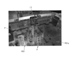
- FIG. 3 is an appearance photograph showing an example of the appearance in the vicinity of the load cell LS of the contact probe inspection apparatus 100 shown in FIG.
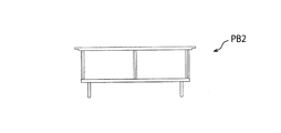
- Figure 4A is a perspective view of the pin board jig PB2 to be examined in a contact probe test apparatus 100.
- Figure 4B is a front view of the pin board jig PB2 shown in Figure 4A.
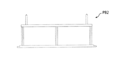
- FIG. 4C is a front view of the pinboard jig PB2 shown in FIG. 4A in the direction of setting in the contact probe inspection apparatus 100.
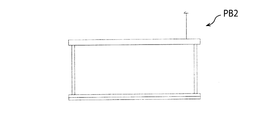
- FIG. 4D is a side view of the pinboard jig PB2 shown in FIG. 4A in the direction of setting in the contact probe inspection apparatus 100.
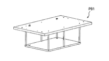
- Figure 5A is a perspective view of the pin board jig PB1 to be examined in a contact probe test apparatus 100.
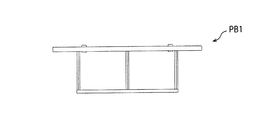
- FIG. 5B is a front view of the pin board jig PB1 shown in FIG. 5A.
- FIG. 5C is a front view of the pinboard jig PB1 shown in FIG. 5A in the direction of setting in the contact probe inspection apparatus 100.
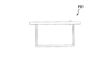
- FIG. 5D is a side view of the pinboard jig PB1 shown in FIG. 5A in the direction of setting in the contact probe inspection apparatus 100.
- FIG. 6 is a view showing an example of the relationship between the measurement position of the contact probe P, the load applied at the measurement position, the upper limit threshold, and the lower limit threshold.
- FIG. 1 is a diagram showing an example of the configuration of the contact probe inspection apparatus 100 according to the first embodiment.
- FIG. 2 is a block diagram showing an example of a system including the configuration of the contact probe inspection apparatus 100 shown in FIG.
- FIG. 3 is an external appearance photograph which shows an example of the external appearance of load cell LS vicinity of the contact probe test
- the contact probe inspection apparatus 100 is in a state of inspecting the contact probe P disposed in the pinboard jig PB1. Further, in the example of FIG. 1, the storage unit M, the output unit D, and the operation unit OP are omitted.
- FIG. 4A is a perspective view of the pin board jig PB2 inspected by the contact probe inspection apparatus 100.
- FIG. 4B is a front view of the pin board jig PB2 shown in Figure 4A.
- FIG. 4C is a front view of the pinboard jig PB2 shown in FIG. 4A in the direction of setting in the contact probe inspection apparatus 100.
- 4D is a side view of the pinboard jig PB2 shown in FIG. 4A in the direction of setting in the contact probe inspection apparatus 100.
- FIG. 5A is a perspective view of the pin board jig PB1 inspected by the contact probe inspection apparatus 100.
- FIG. 5B is a front view of the pinboard jig PB1 shown in FIG. 5A.
- 5C is a front view of the pinboard jig PB1 shown in FIG. 5A in the direction of setting in the contact probe inspection apparatus 100.
- 5D is a side view of the pinboard jig PB1 shown in FIG. 5A in the direction of setting in the contact probe inspection apparatus 100.
- FIG. 6 is a view showing an example of the relationship between the measurement position of the contact probe P, the load applied at the measurement position, the upper limit threshold, and the lower limit threshold.
- the contact probe test apparatus 100 a contact probe P with telescopic structure for measuring a load corresponding to the displacement amount of the contact with inelastic and the stretch to the object, the inspection It is supposed to
- the contact probe inspection apparatus 100 for example, as shown in FIGS. 1 and 2, a support portion H1, H2, and the load cell LS, a drive unit A1, A2, and a control unit PLC, a storage unit M, the output unit D , An imaging unit C (camera), a personal computer PC, and an operation unit OP.
- the support portion H1 is configured to support the pinboard jig PB1 (FIGS. 5A to 5D) in which the contact probe P is disposed.
- another supporting portion H2 is configured to support a pinboard jig PB2 (FIGS. 4A to 4D) in which the contact probe P is disposed.
- Either one of the pinboard jigs PB1 and PB2 is disposed on any one of the support portions H1 and H2 to be inspected.
- the contact probe inspection apparatus 100 is in a state of inspecting the contact probe P disposed in the pinboard jig PB1.
- the contact probe P has a telescopic structure (barrel) for contacting and expanding the object with a tip (plunger) and measuring a load according to the displacement amount of the telescopic. Then, for example, the contact probe P is disposed in the pinboard jig by being accommodated in a socket that accommodates the expansion and contraction structure (barrel) and the socket is connected to the pinboard jig PB1.
- the contact probes P are arranged, for example, in the pinboard jigs PB1 and PB2 so that the expansion and contraction structure is expanded and contracted in the direction perpendicular to the main surface PB1a of the pinboard jig PB1 (FIG. 1).
- the contact probe P is omitted in FIGS. 4A to 4D and 5A to 5D.
- the load cell LS is fixed to the second actuator A2 of the drive units A1 and A2. In contact with the contact probe P, the load cell LS applies a load so that the expansion and contraction structure shrinks to a preset measurement position, and the load applied at the measurement position is measured.
- the drive parts A1 and A2 displace the positions of the load cell LS and the support part.
- the driving unit A1, A2 is provided with a first actuator A1, second actuator A2, a.
- the first actuator A1 is the support portions H1 supporting the pinboard jig PB1 (pinboard jig including a supporting portion H2 which does not support the) adapted to drive in a first direction Y There is.
- the first actuator A1 When the pinboard jig PB2 is supported by the support portion H2, the first actuator A1 does not support the support portion H2 supporting the pinboard jig PB2. including the support portions H1 and) driven in a first direction Y.
- the second actuator A2 drives the load cell LS and the imaging unit C in a second direction X orthogonal to the first direction Y and in a third direction Z orthogonal to the first and second directions Y and X. It is supposed to
- the drive parts A1 and A2 change the relative position of the load cell LS with respect to the contact probe P by the first and second actuators A1 and A2.
- the operation unit OP shown in FIG. 2 receives an operation input of a user, for example, the control unit inspection and the start and stop commands of a command (contact probe P in accordance with the operation input to the PLC, the alignment of the table T A command to instruct adjustment of the position is output.
- control unit PLC shown in FIGS. 1 and 2 is configured to execute a predetermined operation according to the command output from the operation unit OP described above.
- control unit PLC in order to measure the load applied to the elastic structure of the contact probe P at the measurement position, so as to control the load cell LS and the first and second driving portions A1, A2.
- the controller PLC compares the measured load measured at the measurement position by the load cell LS, and a threshold value set in advance corresponding to the measurement position, based on the comparison result, determines the status of the contact probe P It is supposed to
- control unit PLC compares the measured load measured at the measurement position with the upper threshold THa preset corresponding to the measured position, and when the measured load is equal to or higher than the upper threshold THa, It is determined that the expansion and contraction structure of the contact probe P is in a locked state.
- control unit PLC compares the measured load measured at the measurement position with the lower threshold THb lower than the upper threshold THa preset corresponding to the measurement position, and the measured load is less than the lower threshold THb
- the expansion and contraction structure of the contact probe P is broken (the spring is broken) or the load cell LS can not contact the contact probe P (the contact probe P itself is disposed in the pinboard jig PB1 It is judged to be in the state of
- control unit PLC determines that the stretchable structure of the contact probe P is normal.
- control unit PLC applies a first load by the load cell LS so that the expansion and contraction structure of the contact probe P is contracted to a preset first measurement position mP1, and applies the first load at the first measurement position.
- the first measured load ML1 obtained by measuring the load i.e., the first load
- FIG. 6 The first measured load ML1 obtained by measuring the load (i.e., the first load) is obtained (FIG. 6).
- control unit PLC applies a second load by the load cell LS so that the telescopic structure of the contact probe P is contracted to a second measurement position mP2 different from the first measurement position mP1, and the second measurement position mP2
- a second measurement load ML2 obtained by measuring the applied load (that is, the second load) is acquired (FIG. 6).
- control unit PLC applies a third load so that the expansion and contraction structure of the contact probe P is contracted by the load cell LS to a third measurement position mP3 different from the first and second measurement positions mP1 and mP2.
- a third measurement load ML3 obtained by measuring the load (that is, the third load) applied at the measurement position mP3 is obtained (FIG. 6).
- control unit PLC applies a fourth load so that the expansion and contraction structure of the contact probe P is contracted by the load cell LS to a fourth measurement position mP4 different from the first, second and third measurement positions mP1, mP2 and mP3.
- the fourth measurement load ML4 obtained by measuring the load applied at the fourth measurement position mP4 (that is, the fourth load) is acquired (FIG. 6).
- control unit PLC gradually increases the load applied from the load cell LS to the contact probe P, and measures the load applied at each measurement position. First to fourth measured loads ML1 to ML4. to get (Fig. 6).
- control unit PLC based on the first to fourth measuring load mP1, mP2, mP3, MP4 measured, so as to determine the state of the contact probe P.
- the control unit PLC gradually reduces the load applied from the load cell LS to the contact probe P, and obtains the first to fourth measured loads ML1 to ML4 obtained by measuring the applied load at each measurement position. You may do it.
- the contact probe inspection device checks the state of the contact probe, detects the locked probe, and performs replacement etc. in advance. it is possible to prevent the destruction of the substrate by addressing.
- the load at a plurality of points can be measured at an arbitrary position per contact probe, and it is possible to set and judge a threshold value for each, and to store the measured values and judgment data thereof.
- the control unit PLC compares the first measurement load ML1 with a first threshold value set in advance corresponding to the first measurement position mP1, and the second measurement load ML2 and the second measurement load ML2.
- the state of the contact probe P may be determined on the basis of the comparison result with the second threshold value set in advance corresponding to the measurement position mP2.
- control unit PLC compares the above two comparison results with the third measurement load ML3 and the third threshold preset corresponding to the third measurement position mP3, and the fourth measurement.
- the state of the contact probe P may be determined based on the load ML4 and two more results obtained by comparing the fourth threshold value set in advance corresponding to the fourth measurement position mP4.
- control unit PLC controls the load cell LS and the drive unit to measure the load applied at the measurement position to the plurality of contact probes P disposed in the pinboard jig PB1, and the respective measurements are performed.
- the states of the plurality of contact probes P are determined based on the measured load.
- control unit PLC may continuously inspect a plurality of contact probes P arranged in one pin board jig PB1.
- the imaging unit C shown in FIGS. 1 and 2 is disposed in proximity to the load cell LS, and images the appearance of the contact probe P to be inspected by the load cell LS. As described above, the imaging unit C and the load cell LS are displaced together (synchronously) together by the driving units A1 and A2.
- control unit PLC determines the state of the contact probe P based on the information of the measured load inspected by the load cell LS and the image of the appearance of the contact probe P imaged by the imaging unit C. .
- control unit PLC determines whether the expansion and contraction structure of the contact probe P is in a locked state, whether the expansion and contraction structure of the contact probe P is broken (a spring is broken), or the load cell LS An image of the appearance of the contact probe P captured by the imaging unit C as to whether or not the contact probe P can not contact (the contact probe P itself is not disposed in the pinboard jig PB1). Make a judgment based on
- the imaging unit C further captures an image of the pinboard jig PB1 supported by the support unit H1.
- the imaging unit C may image the pinboard jig PB2 supported by another support H2.
- control unit PLC for example, a predefined reference position in the support portion H1, and obtains the position of the supporting portion of the pinboard jig PB1 taken by the imaging unit C, and the difference between, the difference based on, thereby adjusting the displacement amount of the contact probe P by the driving unit A1, A2.
- the imaging unit C is configured such that the imaging direction can be switched so that the alignment position Ta of the contact probe P, the pinboard jig PB1, or the table T can be sequentially imaged.
- the imaging unit C, alignment position Ta of the table T supporting portions H1, H2 is placed (in FIG. 1, as an example, near the end portion in the alignment position Ta of the table T is being positioned) to image the You may do so.
- control unit PLC sets the position of the support unit H1 such that the drive units A1 and A2 arrange the alignment position at a predetermined position set in advance based on the alignment position imaged by the imaging unit C. it may be caused to transition to.
- control unit PLC can measure the load applied to the contact probe P at a predetermined position where measurement can be accurately performed, and can obtain a more accurate measurement load.
- the apparatus can be simplified.
- control unit PLC transmits information data on the state of the contact probe P to the external device 10 that measures the characteristics of the object (such as a semiconductor substrate) using the contact probe P of the pinboard jig PB1. ing.
- the external device 10 is an inspection device (an in-circuit tester (ICT) or a function tester (FCT)) applied to a post-process in a semiconductor manufacturing process.
- ICT in-circuit tester
- FCT function tester
- position data (data included in the external file F) in which the position of the contact probe P in the pinboard jig PB1 to be inspected is defined is input.
- control unit PLC controls the drive unit (first and second actuators A1 and A2) based on the position data input to the personal computer PC, and the load cell LS applies a load to the expansion and contraction structure of the contact probe P. as can, so as to vary the relative position of the load cell LS with respect to the contact probe P.
- pinboard jigs PB1 and PB2 there are many types of pinboard jigs PB1 and PB2 according to various substrates to be inspected. That is, although the position of the contact probe P is different between the pin board jigs BP1 and BP2, the personal computer PC can easily set the apparatus by importing the external file F in which the position of the contact probe P is recorded.
- the control unit PLC may further measure the electrical resistance of the contact probe P in a state where the load cell LS is in contact with the contact probe P.
- control unit PLC may determine the state of the contact probe P based on the information on the measured load of the contact probe P described above and the electric resistance.
- the state of the contact probe P can be determined in more detail.
- control unit PLC predicts the replacement deadline (lifetime) of the contact probe P or calculates the replacement frequency of the contact probe P based on the temporal change of the measured load of the contact probe P measured. You may
- the expansion and contraction structure of the contact probe P includes a spring mechanism, and when the spring mechanism is deteriorated due to a change with time, a load may be reduced even at the same measurement position, and desired expansion and contraction may not be realized.
- the exchange period of the contact probe P is required. Therefore, it is possible to predict the replacement period (life) of the contact probe P or to calculate the replacement frequency of the contact probe P from the correlation between the temporal change of the measured load and the deterioration of the stretchable structure of the contact probe P. It is considered possible.
- the load of the contact probe P can be measured, it can be used as reference data of life prediction and replacement frequency.
- the storage unit M shown in FIG. 2 the judgment result of the state of the contact probe P by the control unit PLC, exchange period of predicted contact probe P (life), and stores the replacement frequency or the like of the calculated contact probe P It is supposed to be.
- the storage unit M is, for example, a non-volatile memory such as a NAND flash memory.
- the output unit D shown in FIG. 1 and FIG. 2 indicates the state (determination result) of the contact probe P determined by the control unit PLC, the predicted replacement deadline (lifetime) of the contact probe P, and the calculated contact probe P It is adapted to output the replacement frequency and the like.
- control unit PLC determines that the expansion and contraction structure of the contact probe P is locked or determines that the expansion and contraction structure of the contact probe P is broken (spring is broken). and it is adapted to output the information indicating the exchange of the probe P is required for the output unit D.
- the output unit D displays, for example, the state (determination result) of the contact probe P determined by the control unit PLC, the estimated replacement period (lifetime) of the contact probe P, the calculated replacement frequency of the contact probe P, and the like. It is a display device.
- the user can check the display of the output unit D, the state (determination result) of the contact probe P to controller PLC determines, exchange period of the predicted contact probe P (lifespan) were calculated It is possible to recognize the frequency of replacement of the contact probe P and the like, and carry out the necessary measures.
- control unit PLC shown in FIGS. 1 and 2 executes a predetermined operation in accordance with the command output from the operation unit OP described above.
- control unit PLC controls the load cell LS and the first and second driving units A1 and A2 in order to measure the load applied to the expansion and contraction structure of the contact probe P at the measurement position.
- control unit PLC controls the drive units (first and second actuators A1 and A2) based on the position data input to the personal computer PC, so that the load cell LS is the contact probe P.
- the relative position of the load cell LS with respect to the contact probe P is changed so that the load can be applied to the expansion and contraction structure.
- control unit PLC includes a measuring load measured at the measurement position by the load cell LS, compares the threshold value set in advance corresponding to the measurement position, based on the comparison result, the state of the contact probe P to decide.
- control unit PLC compares the measured load measured at the measurement position with the upper threshold THa preset corresponding to the measured position, and when the measured load is equal to or higher than the upper threshold THa, It is determined that the expansion and contraction structure of the contact probe P is in a locked state.
- control unit PLC compares the measured load measured at the measurement position with the lower threshold THb lower than the upper threshold THa preset corresponding to the measurement position, and the measured load is less than the lower threshold THb In the case where the expansion and contraction structure of the contact probe P is broken (the spring is broken) or the load cell LS can not contact the contact probe P (the contact probe P itself is disposed in the pinboard jig PB1 it is determined that the not included) state that is.
- control unit PLC determines that the stretchable structure of the contact probe P is normal.
- control unit PLC applies a first load by the load cell LS so that the expansion and contraction structure of the contact probe P is contracted to a preset first measurement position mP1 and applies the first load at the first measurement position.
- the first measured load ML1 is obtained by measuring the load being loaded (ie, the first load) (FIG. 6).
- control unit PLC applies a second load by the load cell LS so that the telescopic structure of the contact probe P is contracted to a second measurement position mP2 different from the first measurement position mP1, and the second measurement position mP2
- a second measured load ML2 obtained by measuring the applied load (that is, the second load) is acquired (FIG. 6).
- control unit PLC applies a third load so that the expansion and contraction structure of the contact probe P is contracted by the load cell LS to a third measurement position mP3 different from the first and second measurement positions mP1 and mP2.
- a third measurement load ML3 obtained by measuring the load applied at the measurement position mP3 (that is, the third load) is acquired (FIG. 6).
- control unit PLC applies a fourth load so that the expansion and contraction structure of the contact probe P is contracted by the load cell LS to a fourth measurement position mP4 different from the first, second and third measurement positions mP1, mP2 and mP3.
- the fourth measurement load ML4 obtained by measuring the load applied at the fourth measurement position mP4 (that is, the fourth load) is acquired (FIG. 6).
- control unit PLC gradually increases the load applied from the load cell LS to the contact probe P, and measures the load applied at each measurement position. First to fourth measured loads ML1 to ML4. to get (Fig. 6).
- control unit PLC determines the state of the contact probe P based on the measured first to fourth measured loads mP1, mP2, mP3 and mP4.
- the control unit PLC gradually reduces the load applied from the load cell LS to the contact probe P, and obtains the first to fourth measured loads ML1 to ML4 obtained by measuring the applied load at each measurement position. You may do it.
- control unit PLC determines the state of the contact probe P based on the information of the measured load inspected by the load cell LS and the image of the appearance of the contact probe P imaged by the imaging unit C. You may do so.
- control unit PLC based on the temporal change of the measured measuring load of the contact probe P, to predict the exchange period of the contact probe P (life), or, contact probe to calculate the frequency of replacement of the P.
- control unit PLC determines that the expansion and contraction structure of the contact probe P is locked or determines that the expansion and contraction structure of the contact probe P is broken (spring is broken). Information is output to the output unit D that the probe P needs to be replaced.
- the user confirms the display on the output unit D to determine the state (determination result) of the contact probe P determined by the control unit PLC, the predicted replacement period (lifetime) of the contact probe P, and the calculated contact. It is possible to recognize the frequency of replacement of the probe P and the like, and to execute the necessary measures.
- the contact probe inspection apparatus inspects a contact probe having an elastic structure for contacting and expanding an object in contact with an object and measuring a load according to the displacement amount of the expansion and contraction.
- the load is set so that the expansion and contraction structure is contracted to a preset measurement position in a state in which the pinboard jig on which the contact probe is disposed is in contact with the support portion H supporting the contact probe
- a load cell LS for applying and measuring a load applied at a measurement position
- driving parts A1 and A2 for displacing the position of the load cell or the position of the support part in order to change the relative position of the load cell with respect to the contact probe Control the load cell and drive to measure the load applied to the telescopic structure of the contact probe at the measurement position That a control unit and a PLC, the.
- control unit compares the measured load measured at the measurement position by the load cell with the threshold set in advance corresponding to the measurement position, and determines the state of the contact probe based on the comparison result.
- the contact probe inspection device checks the state of the contact probe, detects the locked probe, and performs replacement etc. in advance. it is possible to prevent the destruction of the substrate by addressing.
- the load at a plurality of points can be measured at an arbitrary position per contact probe, and it is possible to set and judge a threshold value for each, and to store the measured values and judgment data thereof.
Landscapes
- Physics & Mathematics (AREA)
- General Physics & Mathematics (AREA)
- Measuring Leads Or Probes (AREA)
- Tests Of Electronic Circuits (AREA)
Abstract
コンタクトプローブ検査装置は、コンタクトプローブ(P)が配置されたピンボード治具(PB1)を、支持する支持部(H1、H2)と、コンタクトプローブ(P)に接触した状態で、伸縮構造が予め設定された測定位置まで縮むように荷重を印加し、測定位置で印加している荷重を測定するロードセル(LS)と、コンタクトプローブ(P)に対するロードセル(LS)の相対的な位置を変化させるために、ロードセル(LS)の位置又は支持部(H1、H2)の位置を変位させる駆動部(A1、A2)と、測定位置でコンタクトプローブ(P)の伸縮構造に印加した荷重を測定するために、ロードセル(LS)及び駆動部(A1、A2)を制御する制御部(PLC)と、を備える。
Description
本発明は、コンタクトプローブ検査装置、及び、コンタクトプローブ検査装置の制御方法に関する発明である。
従来、例えば、インサーキットテスタ(ICT)やファンクションテスタ(FCT)で半導体基板等の基板(電子回路基板)を検査するために使用するピンボード治具には、基板の検査パッドや素子の位置に対応して、多数のコンタクトプローブが配置されている。
このコンタクトプローブは、先端が伸縮して対象物に接触する伸縮構造を有し、当該対象物に接触して当該対象物の電気的特性等を検出するのに用いられる。
このコンタクトプローブの伸縮構造は、寿命や外部からの負荷によって伸縮せずにロックする状態になる場合がある。
このように当該伸縮構造がロックした状態でコンタクトプローブが基板に接触すると、基板上の部品やパターンを破壊する可能性がある。
このようにして、当コンタクトプローブの伸縮構造がロックした状態で基板の検査に使用すれば、当該基板に不良が発生する原因となる。
一方、コンタクロプローブは、検査する対象の基板によっては、1つのピンボード治具に対して数百本も配置されるため、人の手による検査は難しい。
そこで、本発明は、伸縮構造を有するコンタクトプローブの状態を自動的に検査することが可能なコンタクトプローブ検査装置を提供することを目的とする。
本発明の一態様に係る実施形態に従ったコンタクトプローブ検査装置は、
対象物に接触して伸縮し且つ当該伸縮の変位量に応じた荷重を測定するための伸縮構造を有するコンタクトプローブを、検査するコンタクトプローブ検査装置であって、
前記コンタクトプローブが配置されたピンボード治具を、支持する支持部と、
前記コンタクトプローブに接触した状態で、前記伸縮構造が予め設定された測定位置まで縮むように荷重を印加し、前記測定位置で印加している荷重を測定するロードセルと、
前記コンタクトプローブに対する前記ロードセルの相対的な位置を変化させるために、前記ロードセルの位置又は前記支持部の位置を変位させる駆動部と、
前記測定位置で前記コンタクトプローブの前記伸縮構造に印加した荷重を測定するために、前記ロードセル及び前記駆動部を制御する制御部と、を備え、
前記制御部は、前記ロードセルにより前記測定位置で測定された測定荷重と、前記測定位置に対応して予め設定された閾値とを比較し、この比較結果に基づいて、前記コンタクトプローブの状態を判断する
ことを特徴とする。
対象物に接触して伸縮し且つ当該伸縮の変位量に応じた荷重を測定するための伸縮構造を有するコンタクトプローブを、検査するコンタクトプローブ検査装置であって、
前記コンタクトプローブが配置されたピンボード治具を、支持する支持部と、
前記コンタクトプローブに接触した状態で、前記伸縮構造が予め設定された測定位置まで縮むように荷重を印加し、前記測定位置で印加している荷重を測定するロードセルと、
前記コンタクトプローブに対する前記ロードセルの相対的な位置を変化させるために、前記ロードセルの位置又は前記支持部の位置を変位させる駆動部と、
前記測定位置で前記コンタクトプローブの前記伸縮構造に印加した荷重を測定するために、前記ロードセル及び前記駆動部を制御する制御部と、を備え、
前記制御部は、前記ロードセルにより前記測定位置で測定された測定荷重と、前記測定位置に対応して予め設定された閾値とを比較し、この比較結果に基づいて、前記コンタクトプローブの状態を判断する
ことを特徴とする。
前記コンタクトプローブ検査装置において、
前記制御部は、
前記測定位置で測定された前記測定荷重と、前記測定位置に対応して予め設定された上限閾値とを比較し、前記測定荷重が、前記上限閾値以上である場合には、前記コンタクトプローブの前記伸縮構造がロックされた状態であると判断し、
前記測定位置で測定された前記測定荷重と、前記測定位置に対応して予め設定された前記上限閾値よりも低い下限閾値とを比較し、前記測定荷重が、前記下限閾値未満である場合には、前記コンタクトプローブの前記伸縮構造が壊れた状態、若しくは、前記ロードセルが前記コンタクトプローブに接触できていない状態であると判断し、
前記測定荷重が前記下限閾値以上、前記上限閾値未満である場合には、前記コンタクトプローブの前記伸縮構造が正常であると判断する
ことを特徴とする。
前記制御部は、
前記測定位置で測定された前記測定荷重と、前記測定位置に対応して予め設定された上限閾値とを比較し、前記測定荷重が、前記上限閾値以上である場合には、前記コンタクトプローブの前記伸縮構造がロックされた状態であると判断し、
前記測定位置で測定された前記測定荷重と、前記測定位置に対応して予め設定された前記上限閾値よりも低い下限閾値とを比較し、前記測定荷重が、前記下限閾値未満である場合には、前記コンタクトプローブの前記伸縮構造が壊れた状態、若しくは、前記ロードセルが前記コンタクトプローブに接触できていない状態であると判断し、
前記測定荷重が前記下限閾値以上、前記上限閾値未満である場合には、前記コンタクトプローブの前記伸縮構造が正常であると判断する
ことを特徴とする。
前記コンタクトプローブ検査装置において、
前記制御部は、
前記ロードセルにより、前記コンタクトプローブの前記伸縮構造が予め設定された第1の測定位置まで縮むように第1の荷重を印加し、前記第1の測定位置で印加している荷重を測定した第1の測定荷重を取得し、
その後、前記コンタクトプローブの前記伸縮構造が前記第1の測定位置と異なる第2の測定位置まで縮むように第2の荷重を印加し、前記第2の測定位置で印加している荷重を測定した第2の測定荷重を取得し、
測定した前記第1及び第2の測定荷重に基づいて、前記コンタクトプローブの状態を判断する
ことを特徴とする。
前記制御部は、
前記ロードセルにより、前記コンタクトプローブの前記伸縮構造が予め設定された第1の測定位置まで縮むように第1の荷重を印加し、前記第1の測定位置で印加している荷重を測定した第1の測定荷重を取得し、
その後、前記コンタクトプローブの前記伸縮構造が前記第1の測定位置と異なる第2の測定位置まで縮むように第2の荷重を印加し、前記第2の測定位置で印加している荷重を測定した第2の測定荷重を取得し、
測定した前記第1及び第2の測定荷重に基づいて、前記コンタクトプローブの状態を判断する
ことを特徴とする。
前記コンタクトプローブ検査装置において、
前記制御部は、
前記第1の測定荷重と、前記第1の測定位置に対応して予め設定された第1の閾値とを比較し、且つ前記第2の測定荷重と、前記第2の測定位置に対応して予め設定された第2の閾値とを比較し、この2つの比較結果に基づいて、前記コンタクトプローブの状態を判断する
ことを特徴とする。
前記制御部は、
前記第1の測定荷重と、前記第1の測定位置に対応して予め設定された第1の閾値とを比較し、且つ前記第2の測定荷重と、前記第2の測定位置に対応して予め設定された第2の閾値とを比較し、この2つの比較結果に基づいて、前記コンタクトプローブの状態を判断する
ことを特徴とする。
前記コンタクトプローブ検査装置において、
前記制御部は、
前記ロードセル及び前記駆動部を制御して、前記ピンボード治具に配置された複数のコンタクトプローブに対して前記測定位置で印加した荷重をそれぞれ測定し、測定されたそれぞれの測定荷重に基づいて、前記複数のコンタクトプローブの状態をそれぞれ判断する
ことを特徴とする。
前記制御部は、
前記ロードセル及び前記駆動部を制御して、前記ピンボード治具に配置された複数のコンタクトプローブに対して前記測定位置で印加した荷重をそれぞれ測定し、測定されたそれぞれの測定荷重に基づいて、前記複数のコンタクトプローブの状態をそれぞれ判断する
ことを特徴とする。
前記コンタクトプローブ検査装置において、
前記駆動部は、
前記ピンボード治具を支持した前記支持部を第1の方向に駆動する第1のアクチュエータと、
前記ロードセルを前記第1の方向に直交する第2の方向及び前記第1及び第2の方向に直交する第3の方向に駆動する第2のアクチュエータと、を備える
ことを特徴とする。
前記駆動部は、
前記ピンボード治具を支持した前記支持部を第1の方向に駆動する第1のアクチュエータと、
前記ロードセルを前記第1の方向に直交する第2の方向及び前記第1及び第2の方向に直交する第3の方向に駆動する第2のアクチュエータと、を備える
ことを特徴とする。
前記コンタクトプローブ検査装置において、
前記制御部による前記コンタクトプローブの状態の判断結果を記憶する記憶部Mをさらに備える
ことを特徴とする。
前記制御部による前記コンタクトプローブの状態の判断結果を記憶する記憶部Mをさらに備える
ことを特徴とする。
前記コンタクトプローブ検査装置において、
前記制御部が判断した前記コンタクトプローブの状態を出力する出力部をさらに備えることを特徴とする。
前記制御部が判断した前記コンタクトプローブの状態を出力する出力部をさらに備えることを特徴とする。
前記コンタクトプローブ検査装置において、
前記出力部は、前記制御部が判断した前記コンタクトプローブの状態を表示する表示装置である
ことを特徴とする。
前記出力部は、前記制御部が判断した前記コンタクトプローブの状態を表示する表示装置である
ことを特徴とする。
前記コンタクトプローブ検査装置において、
前記支持部により支持された前記ピンボード治具を撮像する撮像部をさらに備え、
前記制御部は、
前記支持部における予め規定された基準位置と、前記撮像部により撮像されたピンボード治具の前記支持部における位置と、の間の差を取得し、前記差に基づいて、前記駆動部による前記コンタクトプローブの変移量を調整する
ことを特徴とする。
前記支持部により支持された前記ピンボード治具を撮像する撮像部をさらに備え、
前記制御部は、
前記支持部における予め規定された基準位置と、前記撮像部により撮像されたピンボード治具の前記支持部における位置と、の間の差を取得し、前記差に基づいて、前記駆動部による前記コンタクトプローブの変移量を調整する
ことを特徴とする。
前記コンタクトプローブ検査装置において、
前記撮像部は、
前記ロードセルに近接して配置され、前記ロードセルにより検査される前記コンタクトプローブの外観を撮像するようになっており、
前記制御部は、
前記撮像部により撮像された前記コンタクトプローブの外観の画像に基づいて、前記コンタクトプローブの状態を判断する
ことを特徴とする。
前記撮像部は、
前記ロードセルに近接して配置され、前記ロードセルにより検査される前記コンタクトプローブの外観を撮像するようになっており、
前記制御部は、
前記撮像部により撮像された前記コンタクトプローブの外観の画像に基づいて、前記コンタクトプローブの状態を判断する
ことを特徴とする。
前記コンタクトプローブ検査装置において、
前記制御部は、
前記ピンボード治具のコンタクトプローブを用いて前記対象物の特性を測定する外部装置に、前記コンタクトプローブの状態に関する情報データを送信する
ことを特徴とする。
前記制御部は、
前記ピンボード治具のコンタクトプローブを用いて前記対象物の特性を測定する外部装置に、前記コンタクトプローブの状態に関する情報データを送信する
ことを特徴とする。
前記コンタクトプローブ検査装置において、
検査予定の前記ピンボード治具における前記コンタクトプローブの位置が規定された位置データが入力されるようになっているパソコンをさらに備え、
前記制御部は、
前記パソコンに入力された前記位置データに基づいて前記駆動部を制御して、前記ロードセルが前記コンタクトプローブの前記伸縮構造に負荷を印加できるように、前記コンタクトプローブに対する前記ロードセルの相対的な位置を変化させる
ことを特徴とする。
検査予定の前記ピンボード治具における前記コンタクトプローブの位置が規定された位置データが入力されるようになっているパソコンをさらに備え、
前記制御部は、
前記パソコンに入力された前記位置データに基づいて前記駆動部を制御して、前記ロードセルが前記コンタクトプローブの前記伸縮構造に負荷を印加できるように、前記コンタクトプローブに対する前記ロードセルの相対的な位置を変化させる
ことを特徴とする。
前記コンタクトプローブ検査装置において、
前記制御部は、
前記コンタクトプローブの前記伸縮構造がロックされた状態と判断し、又は、前記コンタクトプローブの前記伸縮構造が壊れた状態であると判断した場合には、前記コンタクトプローブの交換が必要である旨の情報を前記出力部に出力させる
ことを特徴とする。
前記制御部は、
前記コンタクトプローブの前記伸縮構造がロックされた状態と判断し、又は、前記コンタクトプローブの前記伸縮構造が壊れた状態であると判断した場合には、前記コンタクトプローブの交換が必要である旨の情報を前記出力部に出力させる
ことを特徴とする。
本発明の一態様に係る実施形態に従ったコンタクトプローブ検査装置の制御方法は、
対象物に接触して伸縮し且つ当該伸縮の変位量に応じた荷重を測定するための伸縮構造を有するコンタクトプローブを、検査するコンタクトプローブ検査装置であって、前記コンタクトプローブが配置されたピンボード治具を、支持する支持部と、前記コンタクトプローブに接触した状態で、前記伸縮構造が予め設定された測定位置まで縮むように荷重を印加し、前記測定位置で印加している荷重を測定するロードセルと、前記コンタクトプローブに対する前記ロードセルの相対的な位置を変化させるために、前記ロードセルの位置又は前記支持部の位置を変位させる駆動部と、前記測定位置で前記コンタクトプローブの前記伸縮構造に印加した荷重を測定するために、前記ロードセル及び前記駆動部を制御する制御部と、を備えたコンタクトプローブ検査装置の制御方法であって、
前記制御部により、前記ロードセルにより前記測定位置で測定された測定荷重と、前記測定位置に対応して予め設定された閾値とを比較し、この比較結果に基づいて、前記コンタクトプローブの状態を判断する
ことを特徴とする。
対象物に接触して伸縮し且つ当該伸縮の変位量に応じた荷重を測定するための伸縮構造を有するコンタクトプローブを、検査するコンタクトプローブ検査装置であって、前記コンタクトプローブが配置されたピンボード治具を、支持する支持部と、前記コンタクトプローブに接触した状態で、前記伸縮構造が予め設定された測定位置まで縮むように荷重を印加し、前記測定位置で印加している荷重を測定するロードセルと、前記コンタクトプローブに対する前記ロードセルの相対的な位置を変化させるために、前記ロードセルの位置又は前記支持部の位置を変位させる駆動部と、前記測定位置で前記コンタクトプローブの前記伸縮構造に印加した荷重を測定するために、前記ロードセル及び前記駆動部を制御する制御部と、を備えたコンタクトプローブ検査装置の制御方法であって、
前記制御部により、前記ロードセルにより前記測定位置で測定された測定荷重と、前記測定位置に対応して予め設定された閾値とを比較し、この比較結果に基づいて、前記コンタクトプローブの状態を判断する
ことを特徴とする。
本発明の一態様に係るコンタクトプローブ検査装置は、対象物に接触して伸縮し且つ当該伸縮の変位量に応じた荷重を測定するための伸縮構造を有するコンタクトプローブを、検査するコンタクトプローブ検査装置であって、コンタクトプローブが配置されたピンボード治具を、支持する支持部と、コンタクトプローブに接触した状態で、伸縮構造が予め設定された測定位置まで縮むように荷重を印加し、測定位置で印加している荷重を測定するロードセルと、コンタクトプローブに対するロードセルの相対的な位置を変化させるために、ロードセルの位置又は支持部の位置を変位させる駆動部と、測定位置でコンタクトプローブの伸縮構造に印加した荷重を測定するために、ロードセル及び駆動部を制御する制御部と、を備える。
そして、制御部は、ロードセルにより測定位置で測定された測定荷重と、測定位置に対応して予め設定された閾値とを比較し、この比較結果に基づいて、コンタクトプローブの状態を判断する。
これにより、伸縮構造を有するコンタクトプローブの状態を自動的に検査することができる。
特に、ICTやFCTでピンボード治具を使用する前に、本コンタクトプローブ検査装置で検査することにより、コンタクトプローブの状態を確認し、ロックされた状態のプローブを検出し、事前に交換等の対処することで基板の破壊を防ぐことができる。
さらに、コンタクトプローブ1本につき任意位置で複数個所の荷重を計測することができ、それぞれに閾値を設定し、判断すること、またそれらの計測値や判定データを蓄積することができる。
以下、本発明に係る実施形態について図面に基づいて説明する。
図1は、第1の実施形態に係るコンタクトプローブ検査装置100の構成の一例を示す図である。また、図2は、図1に示すコンタクトプローブ検査装置100の構成を含むシステムの一例を示すブロック図である。また、図3は、図1に示すコンタクトプローブ検査装置100のロードセルLS近傍の外観の一例を示す外観写真である。なお、図1の例では、コンタクトプローブ検査装置100は、ピンボード治具PB1に配置されたコンタクトプローブPを検査する状態になっている。また、図1の例では、記憶部M、出力部D、及び操作部OPは、省略されている。
また、図4Aは、コンタクトプローブ検査装置100で検査されるピンボード治具PB2の斜視図である。また、図4Bは、図4Aに示すピンボード治具PB2の正面図である。また、図4Cは、コンタクトプローブ検査装置100にセットする向きの、図4Aに示すピンボード治具PB2の正面図である。また、図4Dは、コンタクトプローブ検査装置100にセットする向きの、図4Aに示すピンボード治具PB2の側面図である。
また、図5Aは、コンタクトプローブ検査装置100で検査されるピンボード治具PB1の斜視図である。また、図5Bは、図5Aに示すピンボード治具PB1の正面図である。また、図5Cは、コンタクトプローブ検査装置100にセットする向きの、図5Aに示すピンボード治具PB1の正面図である。また、図5Dは、コンタクトプローブ検査装置100にセットする向きの、図5Aに示すピンボード治具PB1の側面図である。
また、図6は、コンタクトプローブPの測定位置と、当該測定位置で印加している荷重と、上限閾値と、下限閾値との関係の一例を示す図である。
ここで、第1の実施形態に係るコンタクトプローブ検査装置100は、対象物に接触して伸縮し且つ当該伸縮の変位量に応じた荷重を測定するための伸縮構造を有するコンタクトプローブPを、検査するようになっている。
このコンタクトプローブ検査装置100は、例えば、図1、2に示すように、支持部H1、H2と、ロードセルLSと、駆動部A1、A2と、制御部PLCと、記憶部Mと、出力部Dと、撮像部C(カメラ)と、パソコンPCと、操作部OPと、を備える。
そして、支持部H1は、コンタクトプローブPが配置されたピンボード治具PB1(図5A~図5D)を、支持するようになっている。
また、もう一つの支持部H2は、コンタクトプローブPが配置されたピンボード治具PB2(図4A~図4D)を、支持するようになっている。
これらの支持部H1、H2の何れか一方に、ピンボード治具PB1、PB2の何れか一方が配置されて、検査されるようになっている。
なお、図1の例では、コンタクトプローブ検査装置100は、ピンボード治具PB1に配置されたコンタクトプローブPを検査する状態になっている。
ここで、コンタクトプローブPは、対象物に先端(プランジャー)で接触して伸縮し且つ当該伸縮の変位量に応じた荷重を測定するための伸縮構造(バレル)を有する。そして、例えば、当該伸縮構造(バレル)を収納するソケットに収納され、当該ソケットがピンボード治具PB1に接続されることで、コンタクトプローブPがピンボード治具に配置される。
なお、コンタクトプローブPは、例えば、ピンボード治具PB1の主面PB1aに垂直な方向に伸縮構造が伸縮するように、各ピンボード治具PB1、PB2に配置されている(図1)。なお、図4A~図4D、図5A~図5Dでは、コンタクトプローブPは省略されている。
また、図1に示すように、ロードセルLSは、駆動部A1、A2の第2のアクチュエータA2に固定されている。このロードセルLSは、コンタクトプローブPに接触した状態で、伸縮構造が予め設定された測定位置まで縮むように荷重を印加し、測定位置で印加している荷重を測定するようになっている。
また、駆動部A1、A2は、コンタクトプローブPに対するロードセルLSの相対的な位置を変化させるために、ロードセルLS及び支持部の位置の位置を変位させるようになっている。
この駆動部A1、A2は、第1のアクチュエータA1と、第2のアクチュエータA2と、を備える。
そして、第1のアクチュエータA1は、ピンボード治具PB1を支持した支持部H1を(ピンボード治具を支持していない支持部H2を含めて)第1の方向Yに駆動するようになっている。
なお、ピンボード治具PB2が支持部H2により支持されている場合には、この第1のアクチュエータA1は、ピンボード治具PB2を支持した支持部H2を(ピンボード治具を支持していない支持部H1を含めて)第1の方向Yに駆動する。
また、第2のアクチュエータA2は、ロードセルLS及び撮像部Cを第1の方向Yに直交する第2の方向X及び第1及び第2の方向Y、Xに直交する第3の方向Zに駆動するようになっている。
このように、駆動部A1、A2は、第1、第2のアクチュエータA1、A2により、コンタクトプローブPに対するロードセルLSの相対的な位置を変化させるようになっている。
また、図2に示す操作部OPは、ユーザの操作入力を受け付けて、例えば、制御部PLCに当該操作入力に応じた指令(コンタクトプローブPの検査を開始や中止する命令や、テーブルTのアライメント位置の調整を指示する指令等)を出力するようになっている。
また、図1、図2に示す制御部PLCは、既述の操作部OPから出力された指令に応じて、所定の動作を実行するようになっている。
例えば、制御部PLCは、測定位置でコンタクトプローブPの伸縮構造に印加した荷重を測定するために、ロードセルLS及び第1、第2の駆動部A1、A2を制御するようになっている。
この制御部PLCは、ロードセルLSにより測定位置で測定された測定荷重と、当該測定位置に対応して予め設定された閾値とを比較し、この比較結果に基づいて、コンタクトプローブPの状態を判断するようになっている。
例えば、制御部PLCは、測定位置で測定された測定荷重と、当該測定位置に対応して予め設定された上限閾値THaとを比較し、測定荷重が、上限閾値THa以上である場合には、コンタクトプローブPの伸縮構造がロックされた状態であると判断するようになっている。
さらに、制御部PLCは、測定位置で測定された測定荷重と、当該測定位置に対応して予め設定された上限閾値THaよりも低い下限閾値THbとを比較し、測定荷重が、下限閾値THb未満である場合には、コンタクトプローブPの伸縮構造が壊れた(バネが壊れた)状態、若しくは、ロードセルLSがコンタクトプローブPに接触できていない(当該コンタクトプローブP自体がピンボード治具PB1に配置されていない)状態であると判断するようになっている。
さらに、制御部PLCは、測定荷重が下限閾値THb以上、上限閾値THa未満である場合には、コンタクトプローブPの伸縮構造が正常であると判断するようになっている。
ここで、例えば、制御部PLCは、ロードセルLSにより、コンタクトプローブPの伸縮構造が予め設定された第1の測定位置mP1まで縮むように第1の荷重を印加し、第1の測定位置で印加している荷重(すなわち、第1の荷重)を測定した第1の測定荷重ML1を取得するようになっている(図6)。
その後、制御部PLCは、ロードセルLSにより、コンタクトプローブPの伸縮構造が第1の測定位置mP1と異なる第2の測定位置mP2まで縮むように第2の荷重を印加し、第2の測定位置mP2で印加している荷重(すなわち、第2の荷重)を測定した第2の測定荷重ML2を取得するようになっている(図6)。
その後、制御部PLCは、ロードセルLSにより、コンタクトプローブPの伸縮構造が第1、2の測定位置mP1、mP2と異なる第3の測定位置mP3まで縮むように第3の荷重を印加し、第2の測定位置mP3で印加している荷重(すなわち、第3の荷重)を測定した第3の測定荷重ML3を取得するようになっている(図6)。
その後、制御部PLCは、ロードセルLSにより、コンタクトプローブPの伸縮構造が第1、2、3の測定位置mP1、mP2、mP3と異なる第4の測定位置mP4まで縮むように第4の荷重を印加し、第4の測定位置mP4で印加している荷重(すなわち、第4の荷重)を測定した第4の測定荷重ML4を取得するようになっている(図6)。
このように、制御部PLCは、ロードセルLSからコンタクトプローブPに印加する荷重を段階的に増加させて、各測定位置において印加している荷重を測定した第1~第4の測定荷重ML1~ML4を取得する(図6)。
その後、制御部PLCは、測定した第1ないし第4の測定荷重mP1、mP2、mP3、mP4に基づいて、コンタクトプローブPの状態を判断するようになっている。
なお、制御部PLCは、ロードセルLSからコンタクトプローブPに印加する荷重を段階的に減少させて、各測定位置において印加している荷重を測定した第1~第4の測定荷重ML1~ML4を取得するようにしてもよい。
これにより、伸縮構造を有するコンタクトプローブの状態を自動的に検査することができる。
特に、ICTやFCTでピンボード治具を使用する前に、本コンタクトプローブ検査装置で検査することにより、コンタクトプローブの状態を確認し、ロックされた状態のプローブを検出し、事前に交換等の対処することで基板の破壊を防ぐことができる。
さらに、コンタクトプローブ1本につき任意位置で複数個所の荷重を計測することができ、それぞれに閾値を設定し、判断すること、またそれらの計測値や判定データを蓄積することができる。
なお、制御部PLCは、第1の測定荷重ML1と、第1の測定位置mP1に対応して予め設定された第1の閾値とを比較し、且つ第2の測定荷重ML2と、第2の測定位置mP2に対応して予め設定された第2の閾値とを比較し、この2つの比較結果に基づいて、コンタクトプローブPの状態を判断するようにしてもよい。
さらに、制御部PLCは、上記2つの比較結果と、第3の測定荷重ML3と、第3の測定位置mP3に対応して予め設定された第3の閾値とを比較し、且つ第4の測定荷重ML4と、第4の測定位置mP4に対応して予め設定された第4の閾値とを比較したさらに2つの結果とに基づいて、コンタクトプローブPの状態を判断するようにしてもよい。
また、制御部PLCは、ロードセルLS及び駆動部を制御して、ピンボード治具PB1に配置された複数のコンタクトプローブPに対して測定位置で印加した荷重をそれぞれ測定し、測定されたそれぞれの測定荷重に基づいて、複数のコンタクトプローブPの状態をそれぞれ判断するようになっている。
このように、制御部PLCは、1つのピンボード治具PB1に配置された複数のコンタクトプローブPを連続して検査するようにしてもよい。
ここで、図1、2に示す撮像部Cは、ロードセルLSに近接して配置され、ロードセルLSで検査されるコンタクトプローブPの外観を撮像するようになっている。既述のように、当該撮像部CとロードセルLSとは、駆動部A1、A2により、一緒に連動して(同期して)変位するようになっている。
そして、制御部PLCは、ロードセルLSで検査した測定荷重の情報と、この撮像部Cにより撮像されたコンタクトプローブPの外観の画像に基づいて、コンタクトプローブPの状態を判断するようになっている。
例えば、制御部PLCは、コンタクトプローブPの伸縮構造がロックされた状態であるか否か、コンタクトプローブPの伸縮構造が壊れた(バネが壊れた)状態であるか否か、若しくは、ロードセルLSがコンタクトプローブPに接触できていない(当該コンタクトプローブP自体がピンボード治具PB1に配置されていない)状態であるか否か等を、撮像部Cにより撮像されたコンタクトプローブPの外観の画像に基づいて判断する。
この撮像部Cは、さらに、支持部H1により支持されたピンボード治具PB1を撮像するようになっている。なお、撮像部Cは、もう一つの支持部H2により支持されたピンボード治具PB2を撮像するようにしてもよい。
そして、制御部PLCは、例えば、支持部H1における予め規定された基準位置と、撮像部Cにより撮像されたピンボード治具PB1の支持部における位置と、の間の差を取得し、当該差に基づいて、駆動部A1、A2によるコンタクトプローブPの変移量を調整するようになっている。
なお、この撮像部Cは、コンタクトプローブP、ピンボード治具PB1、又は、テーブルTのアライメント位置Taを、順次撮像できるように、その撮像方向が切り替えられるようになっている。
さらに、撮像部Cは、支持部H1、H2が載置されるテーブルTのアライメント位置Ta(図1では、一例として、テーブルTの端部近傍にアライメント位置Taが位置している)を撮像するようにしてもよい。
そして、制御部PLCは、撮像部Cにより撮像された当該アライメント位置を基準として、駆動部A1、A2により、当該アライメント位置が予め設定された所定位置に配置されるように、支持部H1の位置を変移させるようにしてもよい。
これにより、制御部PLCは、正確に測定が可能な所定位置で、コンタクトプローブPに印加させる荷重を測定して、より正確な測定荷重を得ることができる。
特に、コンタクトプローブPの外観を撮像するための撮像部Cを、アライメント調整のために用いることで、装置の簡略化を図ることができる。
また、制御部PLCは、ピンボード治具PB1のコンタクトプローブPを用いて対象物(半導体基板等)の特性を測定する外部装置10に、コンタクトプローブPの状態に関する情報データを送信するようになっている。
なお、この外部装置10は、半導体製造工程における後工程に適用される検査装置(インサーキットテスタ(ICT)やファンクションテスタ(FCT))である。
これにより、当該外部装置10でピンボード治具PB1のコンタクトプローブPを用いて対象物(半導体基板等)の特性を測定する際に、コンタクトプローブ検査装置100から送信された情報データに基づいて、必要な対応(測定結果の修正や、コンタクトプローブPの交換、使用禁止等)を実行することができる。
また、パソコンPCは、検査予定のピンボード治具PB1におけるコンタクトプローブPの位置が規定された位置データ(外部ファイルFに含まれるデータ)が入力されるようになっている。
そして、制御部PLCは、パソコンPCに入力された位置データに基づいて駆動部(第1、第2のアクチュエータA1、A2)を制御して、ロードセルLSがコンタクトプローブPの伸縮構造に負荷を印加できるように、コンタクトプローブPに対するロードセルLSの相対的な位置を変化させるようになっている。
このように、ピンボード治具PB1、PB2は、検査対象である、さまざまな基板に合わせて多数の種類がある。すなわち、ピンボード治具BP1、BP2は、それぞれコンタクトプローブPの位置が異なるが、パソコンPCは、コンタクトプローブPの位置が記録された外部ファイルFをインポートすることで簡易に装置の設定ができる。
なお、制御部PLCは、ロードセルLSがコンタクトプローブPに接触した状態で、コンタクトプローブPの電気抵抗をさらに測定するようにしてもよい。
そして、制御部PLCは、既述のコンタクトプローブPの測定荷重の情報と当該電気抵抗とに基づいて、コンタクトプローブPの状態を判断するようにしてもよい。
これにより、より詳細に、コンタクトプローブPの状態を判断することができる。
また、制御部PLCは、コンタクトプローブPの測定された測定荷重の経時的な変化に基づいて、コンタクトプローブPの交換期限(寿命)を予測し、又は、コンタクトプローブPの交換頻度を算出するようにしてもよい。
例えば、コンタクトプローブPの伸縮構造は、バネ機構を含んでおり、当該バネ機構が経時的な変化により、劣化すると、同じ測定位置でも荷重が減少して、所望の伸縮を実現できない場合がある。この場合、コンタクトプローブPの交換期限が必要になる。そこで、この測定荷重の経時的な変化とコンタクトプローブPの伸縮構造の劣化の相関関係から、コンタクトプローブPの交換期限(寿命)を予測し、又は、コンタクトプローブPの交換頻度を算出することができると考えられる。
このように、コンタクトプローブPの荷重を測定することができるので、寿命の予測や交換頻度の参考データとすることができる。
また、図2に示す記憶部Mは、制御部PLCによるコンタクトプローブPの状態の判断結果、予測されたコンタクトプローブPの交換期限(寿命)、算出されたコンタクトプローブPの交換頻度等を記憶するようになっている。この記憶部Mは、例えば、NAND型フラッシュメモリ等の不揮発性メモリである。
そして、図1、図2に示す出力部Dは、制御部PLCが判断したコンタクトプローブPの状態(判断結果)、予測されたコンタクトプローブPの交換期限(寿命)、算出されたコンタクトプローブPの交換頻度等を出力するようになっている。
特に、制御部PLCは、コンタクトプローブPの伸縮構造がロックされた状態と判断し、又は、コンタクトプローブPの伸縮構造が壊れた(バネが壊れた)状態であると判断した場合には、コンタクトプローブPの交換が必要である旨の情報を出力部Dに出力させるようになっている。
この出力部Dは、例えば、制御部PLCが判断したコンタクトプローブPの状態(判断結果)、予測されたコンタクトプローブPの交換期限(寿命)、算出されたコンタクトプローブPの交換頻度等を表示する表示装置である。
これにより、ユーザは、この出力部Dの表示を確認することにより、制御部PLCが判断したコンタクトプローブPの状態(判断結果)、予測されたコンタクトプローブPの交換期限(寿命)、算出されたコンタクトプローブPの交換頻度等を認識して、必要な対応を実行することができる。
次に、以上のような構成を有するコンタクトプローブ検査装置100の制御方法の一例について、説明する。
既述のように、図1、図2に示す制御部PLCは、既述の操作部OPから出力された指令に応じて、所定の動作を実行する。
例えば、制御部PLCは、測定位置でコンタクトプローブPの伸縮構造に印加した荷重を測定するために、ロードセルLS及び第1、第2の駆動部A1、A2を制御する。特に、既述のように、制御部PLCは、パソコンPCに入力された位置データに基づいて駆動部(第1、第2のアクチュエータA1、A2)を制御して、ロードセルLSがコンタクトプローブPの伸縮構造に負荷を印加できるように、コンタクトプローブPに対するロードセルLSの相対的な位置を変化させる。
そして、制御部PLCは、ロードセルLSにより測定位置で測定された測定荷重と、当該測定位置に対応して予め設定された閾値とを比較し、この比較結果に基づいて、コンタクトプローブPの状態を判断する。
例えば、制御部PLCは、測定位置で測定された測定荷重と、当該測定位置に対応して予め設定された上限閾値THaとを比較し、測定荷重が、上限閾値THa以上である場合には、コンタクトプローブPの伸縮構造がロックされた状態であると判断する。
さらに、制御部PLCは、測定位置で測定された測定荷重と、当該測定位置に対応して予め設定された上限閾値THaよりも低い下限閾値THbとを比較し、測定荷重が、下限閾値THb未満である場合には、コンタクトプローブPの伸縮構造が壊れた(バネが壊れた)状態、若しくは、ロードセルLSがコンタクトプローブPに接触できていない(当該コンタクトプローブP自体がピンボード治具PB1に配置されていない)状態であると判断する。
さらに、制御部PLCは、測定荷重が下限閾値THb以上、上限閾値THa未満である場合には、コンタクトプローブPの伸縮構造が正常であると判断する。
より詳しくは、例えば、制御部PLCは、ロードセルLSにより、コンタクトプローブPの伸縮構造が予め設定された第1の測定位置mP1まで縮むように第1の荷重を印加し、第1の測定位置で印加している荷重(すなわち、第1の荷重)を測定した第1の測定荷重ML1を取得する(図6)。
その後、制御部PLCは、ロードセルLSにより、コンタクトプローブPの伸縮構造が第1の測定位置mP1と異なる第2の測定位置mP2まで縮むように第2の荷重を印加し、第2の測定位置mP2で印加している荷重(すなわち、第2の荷重)を測定した第2の測定荷重ML2を取得する(図6)。
その後、制御部PLCは、ロードセルLSにより、コンタクトプローブPの伸縮構造が第1、2の測定位置mP1、mP2と異なる第3の測定位置mP3まで縮むように第3の荷重を印加し、第2の測定位置mP3で印加している荷重(すなわち、第3の荷重)を測定した第3の測定荷重ML3を取得する(図6)。
その後、制御部PLCは、ロードセルLSにより、コンタクトプローブPの伸縮構造が第1、2、3の測定位置mP1、mP2、mP3と異なる第4の測定位置mP4まで縮むように第4の荷重を印加し、第4の測定位置mP4で印加している荷重(すなわち、第4の荷重)を測定した第4の測定荷重ML4を取得する(図6)。
このように、制御部PLCは、ロードセルLSからコンタクトプローブPに印加する荷重を段階的に増加させて、各測定位置において印加している荷重を測定した第1~第4の測定荷重ML1~ML4を取得する(図6)。
その後、制御部PLCは、測定した第1ないし第4の測定荷重mP1、mP2、mP3、mP4に基づいて、コンタクトプローブPの状態を判断する。
なお、制御部PLCは、ロードセルLSからコンタクトプローブPに印加する荷重を段階的に減少させて、各測定位置において印加している荷重を測定した第1~第4の測定荷重ML1~ML4を取得するようにしてもよい。
これにより、伸縮構造を有するコンタクトプローブの状態を自動的に検査することができる。
なお、既述のように、制御部PLCは、ロードセルLSで検査した測定荷重の情報と、撮像部Cにより撮像されたコンタクトプローブPの外観の画像に基づいて、コンタクトプローブPの状態を判断するようにしてもよい。
そして、例えば、既述のように、制御部PLCは、コンタクトプローブPの測定された測定荷重の経時的な変化に基づいて、コンタクトプローブPの交換期限(寿命)を予測し、又は、コンタクトプローブPの交換頻度を算出する。
特に、制御部PLCは、コンタクトプローブPの伸縮構造がロックされた状態と判断し、又は、コンタクトプローブPの伸縮構造が壊れた(バネが壊れた)状態であると判断した場合には、コンタクトプローブPの交換が必要である旨の情報を出力部Dに出力させる。
そして、ユーザは、この出力部Dの表示を確認することにより、制御部PLCが判断したコンタクトプローブPの状態(判断結果)、予測されたコンタクトプローブPの交換期限(寿命)、算出されたコンタクトプローブPの交換頻度等を認識して、必要な対応を実行することができる。
さらに、既述のように、制御部PLCは、ピンボード治具PB1のコンタクトプローブPを用いて対象物(半導体基板等)の特性を測定する外部装置10に、得られたコンタクトプローブPの状態に関する情報データを送信する。
これにより、当該外部装置10でピンボード治具PB1のコンタクトプローブPを用いて対象物(半導体基板等)の特性を測定する際に、コンタクトプローブ検査装置100から送信された情報データに基づいて、必要な対応(測定結果の修正や、コンタクトプローブPの交換、使用禁止等)を実行することができる。
以上のように、本発明の一態様に係るコンタクトプローブ検査装置は、対象物に接触して伸縮し且つ当該伸縮の変位量に応じた荷重を測定するための伸縮構造を有するコンタクトプローブを、検査するコンタクトプローブ検査装置であって、コンタクトプローブが配置されたピンボード治具を、支持する支持部Hと、コンタクトプローブに接触した状態で、伸縮構造が予め設定された測定位置まで縮むように荷重を印加し、測定位置で印加している荷重を測定するロードセルLSと、コンタクトプローブに対するロードセルの相対的な位置を変化させるために、ロードセルの位置又は支持部の位置を変位させる駆動部A1、A2と、測定位置でコンタクトプローブの伸縮構造に印加した荷重を測定するために、ロードセル及び駆動部を制御する制御部PLCと、を備える。
そして、制御部は、ロードセルにより測定位置で測定された測定荷重と、測定位置に対応して予め設定された閾値とを比較し、この比較結果に基づいて、コンタクトプローブの状態を判断する。
これにより、伸縮構造を有するコンタクトプローブの状態を自動的に検査することができる。
特に、ICTやFCTでピンボード治具を使用する前に、本コンタクトプローブ検査装置で検査することにより、コンタクトプローブの状態を確認し、ロックされた状態のプローブを検出し、事前に交換等の対処することで基板の破壊を防ぐことができる。
さらに、コンタクトプローブ1本につき任意位置で複数個所の荷重を計測することができ、それぞれに閾値を設定し、判断すること、またそれらの計測値や判定データを蓄積することができる。
本発明のいくつかの実施形態を説明したが、これらの実施形態は、例として提示したものであり、発明の範囲を限定することは意図していない。これら実施形態は、その他の様々な形態で実施されることが可能であり、発明の要旨を逸脱しない範囲で、種々の省略、置き換え、変更を行うことができる。これら実施形態やその変形は、発明の範囲や要旨に含まれると同様に、特許請求の範囲に記載された発明とその均等の範囲に含まれるものである。
100 コンタクトプローブ検査装置
H1、H2 支持部
LS ロードセル
A1、A2 駆動部
PLC 制御部
M 記憶部
D 出力部
C 撮像部(カメラ)
PC パソコン
OP 操作部
H1、H2 支持部
LS ロードセル
A1、A2 駆動部
PLC 制御部
M 記憶部
D 出力部
C 撮像部(カメラ)
PC パソコン
OP 操作部
Claims (15)
- 対象物に接触して伸縮し且つ当該伸縮の変位量に応じた荷重を測定するための伸縮構造を有するコンタクトプローブを、検査するコンタクトプローブ検査装置であって、
前記コンタクトプローブが配置されたピンボード治具を、支持する支持部と、
前記コンタクトプローブに接触した状態で、前記伸縮構造が予め設定された測定位置まで縮むように荷重を印加し、前記測定位置で印加している荷重を測定するロードセルと、
前記コンタクトプローブに対する前記ロードセルの相対的な位置を変化させるために、前記ロードセルの位置又は前記支持部の位置を変位させる駆動部と、
前記測定位置で前記コンタクトプローブの前記伸縮構造に印加した荷重を測定するために、前記ロードセル及び前記駆動部を制御する制御部と、を備え、
前記制御部は、前記ロードセルにより前記測定位置で測定された測定荷重と、前記測定位置に対応して予め設定された閾値とを比較し、この比較結果に基づいて、前記コンタクトプローブの状態を判断する
ことを特徴とするコンタクトプローブ検査装置。 - 前記制御部は、
前記測定位置で測定された前記測定荷重と、前記測定位置に対応して予め設定された上限閾値とを比較し、前記測定荷重が、前記上限閾値以上である場合には、前記コンタクトプローブの前記伸縮構造がロックされた状態であると判断し、
前記測定位置で測定された前記測定荷重と、前記測定位置に対応して予め設定された前記上限閾値よりも低い下限閾値とを比較し、前記測定荷重が、前記下限閾値未満である場合には、前記コンタクトプローブの前記伸縮構造が壊れた状態、若しくは、前記ロードセルが前記コンタクトプローブに接触できていない状態であると判断し、
前記測定荷重が前記下限閾値以上、前記上限閾値未満である場合には、前記コンタクトプローブの前記伸縮構造が正常であると判断する
ことを特徴とする請求項1に記載のコンタクトプローブ検査装置。 - 前記制御部は、
前記ロードセルにより、前記コンタクトプローブの前記伸縮構造が予め設定された第1の測定位置まで縮むように第1の荷重を印加し、前記第1の測定位置で印加している荷重を測定した第1の測定荷重を取得し、
その後、前記コンタクトプローブの前記伸縮構造が前記第1の測定位置と異なる第2の測定位置まで縮むように第2の荷重を印加し、前記第2の測定位置で印加している荷重を測定した第2の測定荷重を取得し、
測定した前記第1及び第2の測定荷重に基づいて、前記コンタクトプローブの状態を判断する
ことを特徴とする請求項1に記載のコンタクトプローブ検査装置。 - 前記制御部は、
前記第1の測定荷重と、前記第1の測定位置に対応して予め設定された第1の閾値とを比較し、且つ前記第2の測定荷重と、前記第2の測定位置に対応して予め設定された第2の閾値とを比較し、この2つの比較結果に基づいて、前記コンタクトプローブの状態を判断する
ことを特徴とする請求項3に記載のコンタクトプローブ検査装置。 - 前記制御部は、
前記ロードセル及び前記駆動部を制御して、前記ピンボード治具に配置された複数のコンタクトプローブに対して前記測定位置で印加した荷重をそれぞれ測定し、測定されたそれぞれの測定荷重に基づいて、前記複数のコンタクトプローブの状態をそれぞれ判断する
ことを特徴とする請求項1に記載のコンタクトプローブ検査装置。 - 前記駆動部は、
前記ピンボード治具を支持した前記支持部を第1の方向に駆動する第1のアクチュエータと、
前記ロードセルを前記第1の方向に直交する第2の方向及び前記第1及び第2の方向に直交する第3の方向に駆動する第2のアクチュエータと、を備える
ことを特徴とする請求項1に記載のコンタクトプローブ検査装置。 - 前記制御部による前記コンタクトプローブの状態の判断結果を記憶する記憶部Mをさらに備える
ことを特徴とする請求項1に記載のコンタクトプローブ検査装置。 - 前記制御部が判断した前記コンタクトプローブの状態を出力する出力部をさらに備えることを特徴とする請求項1に記載のコンタクトプローブ検査装置。
- 前記出力部は、前記制御部が判断した前記コンタクトプローブの状態を表示する表示装置である
ことを特徴とする請求項8に記載のコンタクトプローブ検査装置。 - 前記支持部により支持された前記ピンボード治具を撮像する撮像部をさらに備え、
前記制御部は、
前記支持部における予め規定された基準位置と、前記撮像部により撮像されたピンボード治具の前記支持部における位置と、の間の差を取得し、前記差に基づいて、前記駆動部による前記コンタクトプローブの変移量を調整する
ことを特徴とする請求項1に記載のコンタクトプローブ検査装置。 - 前記撮像部は、
前記ロードセルに近接して配置され、前記ロードセルにより検査される前記コンタクトプローブの外観を撮像するようになっており、
前記制御部は、
前記撮像部により撮像された前記コンタクトプローブの外観の画像に基づいて、前記コンタクトプローブの状態を判断する
ことを特徴とする請求項10に記載のコンタクトプローブ検査装置。 - 前記制御部は、
前記ピンボード治具のコンタクトプローブを用いて前記対象物の特性を測定する外部装置に、前記コンタクトプローブの状態に関する情報データを送信する
ことを特徴とする請求項2に記載のコンタクトプローブ検査装置。 - 検査予定の前記ピンボード治具における前記コンタクトプローブの位置が規定された位置データが入力されるようになっているパソコンをさらに備え、
前記制御部は、
前記パソコンに入力された前記位置データに基づいて前記駆動部を制御して、前記ロードセルが前記コンタクトプローブの前記伸縮構造に負荷を印加できるように、前記コンタクトプローブに対する前記ロードセルの相対的な位置を変化させる
ことを特徴とする請求項2に記載のコンタクトプローブ検査装置。 - 前記制御部は、
前記コンタクトプローブの前記伸縮構造がロックされた状態と判断し、又は、前記コンタクトプローブの前記伸縮構造が壊れた状態であると判断した場合には、前記コンタクトプローブの交換が必要である旨の情報を前記出力部に出力させる
ことを特徴とする請求項9に記載のコンタクトプローブ検査装置。 - 対象物に接触して伸縮し且つ当該伸縮の変位量に応じた荷重を測定するための伸縮構造を有するコンタクトプローブを、検査するコンタクトプローブ検査装置であって、前記コンタクトプローブが配置されたピンボード治具を、支持する支持部と、前記コンタクトプローブに接触した状態で、前記伸縮構造が予め設定された測定位置まで縮むように荷重を印加し、前記測定位置で印加している荷重を測定するロードセルと、前記コンタクトプローブに対する前記ロードセルの相対的な位置を変化させるために、前記ロードセルの位置又は前記支持部の位置を変位させる駆動部と、前記測定位置で前記コンタクトプローブの前記伸縮構造に印加した荷重を測定するために、前記ロードセル及び前記駆動部を制御する制御部と、を備えたコンタクトプローブ検査装置の制御方法であって、
前記制御部により、前記ロードセルにより前記測定位置で測定された測定荷重と、前記測定位置に対応して予め設定された閾値とを比較し、この比較結果に基づいて、前記コンタクトプローブの状態を判断する
ことを特徴とするコンタクトプローブ検査装置の制御方法。
Priority Applications (2)
| Application Number | Priority Date | Filing Date | Title |
|---|---|---|---|
| PCT/JP2017/023054 WO2018235233A1 (ja) | 2017-06-22 | 2017-06-22 | コンタクトプローブ検査装置、及び、コンタクトプローブ検査装置の制御方法 |
| JP2019503381A JPWO2018235233A1 (ja) | 2017-06-22 | 2017-06-22 | コンタクトプローブ検査装置、及び、コンタクトプローブ検査装置の制御方法 |
Applications Claiming Priority (1)
| Application Number | Priority Date | Filing Date | Title |
|---|---|---|---|
| PCT/JP2017/023054 WO2018235233A1 (ja) | 2017-06-22 | 2017-06-22 | コンタクトプローブ検査装置、及び、コンタクトプローブ検査装置の制御方法 |
Publications (1)
| Publication Number | Publication Date |
|---|---|
| WO2018235233A1 true WO2018235233A1 (ja) | 2018-12-27 |
Family
ID=64737017
Family Applications (1)
| Application Number | Title | Priority Date | Filing Date |
|---|---|---|---|
| PCT/JP2017/023054 Ceased WO2018235233A1 (ja) | 2017-06-22 | 2017-06-22 | コンタクトプローブ検査装置、及び、コンタクトプローブ検査装置の制御方法 |
Country Status (2)
| Country | Link |
|---|---|
| JP (1) | JPWO2018235233A1 (ja) |
| WO (1) | WO2018235233A1 (ja) |
Cited By (1)
| Publication number | Priority date | Publication date | Assignee | Title |
|---|---|---|---|---|
| WO2020129135A1 (ja) * | 2018-12-17 | 2020-06-25 | 株式会社東芝 | プローブピン検査機構および検査装置 |
Citations (4)
| Publication number | Priority date | Publication date | Assignee | Title |
|---|---|---|---|---|
| JPH04335162A (ja) * | 1991-05-13 | 1992-11-24 | Hitachi Ltd | 検査装置 |
| JP2006128452A (ja) * | 2004-10-29 | 2006-05-18 | Seiko Epson Corp | プローブカード及びプローバー装置、半導体装置の製造方法 |
| US20130106456A1 (en) * | 2010-05-21 | 2013-05-02 | University Of Virginia Patent Foundation | Micromachined on-wafer probes and related method |
| JP2013238554A (ja) * | 2012-05-17 | 2013-11-28 | Kaga Electronics Co Ltd | 検査装置 |
Family Cites Families (1)
| Publication number | Priority date | Publication date | Assignee | Title |
|---|---|---|---|---|
| JP2008071999A (ja) * | 2006-09-15 | 2008-03-27 | Ricoh Co Ltd | 半導体装置及びその検査方法並びに半導体装置の検査装置の検査方法 |
-
2017
- 2017-06-22 WO PCT/JP2017/023054 patent/WO2018235233A1/ja not_active Ceased
- 2017-06-22 JP JP2019503381A patent/JPWO2018235233A1/ja active Pending
Patent Citations (4)
| Publication number | Priority date | Publication date | Assignee | Title |
|---|---|---|---|---|
| JPH04335162A (ja) * | 1991-05-13 | 1992-11-24 | Hitachi Ltd | 検査装置 |
| JP2006128452A (ja) * | 2004-10-29 | 2006-05-18 | Seiko Epson Corp | プローブカード及びプローバー装置、半導体装置の製造方法 |
| US20130106456A1 (en) * | 2010-05-21 | 2013-05-02 | University Of Virginia Patent Foundation | Micromachined on-wafer probes and related method |
| JP2013238554A (ja) * | 2012-05-17 | 2013-11-28 | Kaga Electronics Co Ltd | 検査装置 |
Cited By (3)
| Publication number | Priority date | Publication date | Assignee | Title |
|---|---|---|---|---|
| WO2020129135A1 (ja) * | 2018-12-17 | 2020-06-25 | 株式会社東芝 | プローブピン検査機構および検査装置 |
| JPWO2020129135A1 (ja) * | 2018-12-17 | 2021-09-27 | 株式会社東芝 | プローブピン検査機構および検査装置 |
| JP7039730B2 (ja) | 2018-12-17 | 2022-03-22 | 株式会社東芝 | プローブピン検査機構および検査装置 |
Also Published As
| Publication number | Publication date |
|---|---|
| JPWO2018235233A1 (ja) | 2019-06-27 |
Similar Documents
| Publication | Publication Date | Title |
|---|---|---|
| US20150362552A1 (en) | Probe Device | |
| WO2018159190A1 (ja) | 検査システム、および検査システムの故障解析・予知方法 | |
| JP4532570B2 (ja) | 回路基板検査装置および回路基板検査方法 | |
| TW201317571A (zh) | 配線缺陷檢查方法、配線缺陷檢查裝置、配線缺陷檢查程式及配線缺陷檢查程式紀錄媒體 | |
| KR20170038050A (ko) | 디바이스의 검사 방법, 프로브 카드, 인터포저 및 검사 장치 | |
| KR20090060772A (ko) | 반도체 디바이스 테스트 시스템 | |
| US9442156B2 (en) | Alignment support device and alignment support method for probe device | |
| JP2013238554A (ja) | 検査装置 | |
| JP2006258686A5 (ja) | ||
| JP5215148B2 (ja) | 絶縁検査装置および絶縁検査方法 | |
| JP2006200946A (ja) | 基板検査装置、基板検査プログラム及び基板検査方法 | |
| WO2018235233A1 (ja) | コンタクトプローブ検査装置、及び、コンタクトプローブ検査装置の制御方法 | |
| JP4748181B2 (ja) | 半導体装置の試験装置および試験方法 | |
| JPWO2018235234A1 (ja) | コンタクトプローブ検査装置、及び、コンタクトプローブ検査装置の制御方法 | |
| CN115951288A (zh) | 电容校准系统、方法、设备及存储介质 | |
| KR101553206B1 (ko) | 프로브 카드 검사 시스템 및 프로브 카드의 릴레이 구동 검사 방법 | |
| JP4980870B2 (ja) | 半導体検査装置及びその制御方法 | |
| KR20170110523A (ko) | 회로 기판의 검사 방법, 검사 장치, 및 프로그램 | |
| CN102124552B (zh) | 修正探针卡及卡盘板间的平行性的装置及方法 | |
| JP6479441B2 (ja) | 基板検査装置および基板検査方法 | |
| US20150042367A1 (en) | Thickness measurement device and method for measuring thickness | |
| JP2010054455A (ja) | 半導体試験装置及びテストボード | |
| KR101415984B1 (ko) | 반도체 소자 테스트용 핸들러장치의 디바이스 컨택 제어방법 | |
| JP2022091532A (ja) | コンデンサ検査装置、方法及びプログラム | |
| KR101957199B1 (ko) | 검사장치 |
Legal Events
| Date | Code | Title | Description |
|---|---|---|---|
| ENP | Entry into the national phase |
Ref document number: 2019503381 Country of ref document: JP Kind code of ref document: A |
|
| 121 | Ep: the epo has been informed by wipo that ep was designated in this application |
Ref document number: 17914305 Country of ref document: EP Kind code of ref document: A1 |
|
| NENP | Non-entry into the national phase |
Ref country code: DE |
|
| 122 | Ep: pct application non-entry in european phase |
Ref document number: 17914305 Country of ref document: EP Kind code of ref document: A1 |