WO2018230984A1 - 동기 신호 블록을 측정하는 방법 및 이를 위한 장치 - Google Patents
동기 신호 블록을 측정하는 방법 및 이를 위한 장치 Download PDFInfo
- Publication number
- WO2018230984A1 WO2018230984A1 PCT/KR2018/006748 KR2018006748W WO2018230984A1 WO 2018230984 A1 WO2018230984 A1 WO 2018230984A1 KR 2018006748 W KR2018006748 W KR 2018006748W WO 2018230984 A1 WO2018230984 A1 WO 2018230984A1
- Authority
- WO
- WIPO (PCT)
- Prior art keywords
- ssb
- information
- cell
- rsrp
- measurement
- Prior art date
Links
Images


Classifications
-
- H—ELECTRICITY
- H04—ELECTRIC COMMUNICATION TECHNIQUE
- H04J—MULTIPLEX COMMUNICATION
- H04J11/00—Orthogonal multiplex systems, e.g. using WALSH codes
- H04J11/0069—Cell search, i.e. determining cell identity [cell-ID]
-
- H—ELECTRICITY
- H04—ELECTRIC COMMUNICATION TECHNIQUE
- H04B—TRANSMISSION
- H04B17/00—Monitoring; Testing
- H04B17/30—Monitoring; Testing of propagation channels
- H04B17/309—Measuring or estimating channel quality parameters
- H04B17/318—Received signal strength
-
- H—ELECTRICITY
- H04—ELECTRIC COMMUNICATION TECHNIQUE
- H04J—MULTIPLEX COMMUNICATION
- H04J11/00—Orthogonal multiplex systems, e.g. using WALSH codes
-
- H—ELECTRICITY
- H04—ELECTRIC COMMUNICATION TECHNIQUE
- H04L—TRANSMISSION OF DIGITAL INFORMATION, e.g. TELEGRAPHIC COMMUNICATION
- H04L1/00—Arrangements for detecting or preventing errors in the information received
- H04L1/0001—Systems modifying transmission characteristics according to link quality, e.g. power backoff
- H04L1/0023—Systems modifying transmission characteristics according to link quality, e.g. power backoff characterised by the signalling
- H04L1/0026—Transmission of channel quality indication
-
- H—ELECTRICITY
- H04—ELECTRIC COMMUNICATION TECHNIQUE
- H04L—TRANSMISSION OF DIGITAL INFORMATION, e.g. TELEGRAPHIC COMMUNICATION
- H04L5/00—Arrangements affording multiple use of the transmission path
- H04L5/003—Arrangements for allocating sub-channels of the transmission path
- H04L5/0048—Allocation of pilot signals, i.e. of signals known to the receiver
- H04L5/0051—Allocation of pilot signals, i.e. of signals known to the receiver of dedicated pilots, i.e. pilots destined for a single user or terminal
-
- H—ELECTRICITY
- H04—ELECTRIC COMMUNICATION TECHNIQUE
- H04W—WIRELESS COMMUNICATION NETWORKS
- H04W24/00—Supervisory, monitoring or testing arrangements
- H04W24/08—Testing, supervising or monitoring using real traffic
-
- H—ELECTRICITY
- H04—ELECTRIC COMMUNICATION TECHNIQUE
- H04W—WIRELESS COMMUNICATION NETWORKS
- H04W24/00—Supervisory, monitoring or testing arrangements
- H04W24/10—Scheduling measurement reports ; Arrangements for measurement reports
-
- H—ELECTRICITY
- H04—ELECTRIC COMMUNICATION TECHNIQUE
- H04W—WIRELESS COMMUNICATION NETWORKS
- H04W56/00—Synchronisation arrangements
-
- H—ELECTRICITY
- H04—ELECTRIC COMMUNICATION TECHNIQUE
- H04W—WIRELESS COMMUNICATION NETWORKS
- H04W56/00—Synchronisation arrangements
- H04W56/001—Synchronization between nodes
Definitions
- the present invention relates to a method and apparatus for measuring a synchronization signal block (SSB), and more particularly, to measuring SSBs transmitted by a plurality of cells located around a UE.
- the present invention relates to a method for setting SSB measurement timing for each cell and an apparatus therefor.
- next generation 5G system which is an improved wireless broadband communication than the existing LTE system, is required.
- eMBB Enhanced Mobile BroadBand
- URLLC Ultra-reliability and low-latency communication
- mMTC Massive Machine-Type Communications
- eMBB is a next generation mobile communication scenario having characteristics such as High Spectrum Efficiency, High User Experienced Data Rate, High Peak Data Rate, and URLLC is a next generation mobile communication scenario having characteristics such as Ultra Reliable, Ultra Low Latency, Ultra High Availability, etc.
- mMTC is a next generation mobile communication scenario with low cost, low energy, short packet, and mass connectivity. (e.g., IoT).
- the present invention provides a method for measuring a synchronization signal block (SSB) and an apparatus therefor.
- SSB synchronization signal block
- a cell list including information of one or more first cells, the one or more cells
- a reference signal received power (RSRP) of the SSBs of the one or more first cells is measured based on an SSB measurement window, and based on a second SSB measurement window set up using the second SSB transmission period information. It may include measuring the RSRP for the SSB of the second cell.
- RSRP reference signal received power
- the first and second SSB measurement windows may be set up by further using information about an offset and a duration, which are received together with at least one of the first and second SSB transmission period information. have.
- first and second SSB measurement windows may be set using information on the same offset and the same measurement interval.
- the SSBs of the first and second cells may include a primary synchronization signal (PSS), a secondary synchronization signal (SSS), and a physical broadcasting channel (PBCH).
- PSS primary synchronization signal
- SSS secondary synchronization signal
- PBCH physical broadcasting channel
- RSRP for the SSBs of the first and second cells may be measured using resource element (RE) to which SSS is transmitted and a demodulation reference signal (DMRS) received in a region where the PBCH is received.
- RE resource element
- DMRS demodulation reference signal
- the RSRP of the SSBs of the first and second cells may be additionally measured using the CSI-RS.
- RSRP may not be measured at times other than the first and second SSB measurement windows.
- a terminal for measuring a Synchronization Signal Block comprising: a transceiver for transmitting and receiving a signal; And a processor for controlling the transceiver, wherein the processor is not included in the cell list including information of one or more first cells, first SSB period information for the one or more cells, and the cell list.
- SSB Synchronization Signal Block
- the transceiver to receive second SSB transmission period information for a second cell that is not present, and based on the first SSB measurement window set up using the first SSB transmission period information, the one or more first cells RSRP (Reference Signal Received Power) for SSBs of the UEs and RSRP of SSBs transmitted by the second cell is measured based on a second SSB measurement window set up using the second SSB transmission period information. It may include doing.
- RSRP Reference Signal Received Power
- the first and second SSB measurement windows may be set by further using information about an offset and a duration, which are received together with at least one of the first and second SSB transmission period information.
- first and second SSB measurement windows may be set using information on the same offset and the same measurement interval.
- the SSBs of the first and second cells may include a primary synchronization signal (PSS), a secondary synchronization signal (SSS), and a physical broadcasting channel (PBCH), and the first and second cells.
- PSS primary synchronization signal
- SSS secondary synchronization signal
- PBCH physical broadcasting channel
- the RSRP for the SSB may be measured by using resource elements (REs) through which the SSS is transmitted and a demodulation reference signal (DMRS) received in an area where the PBCH is received.
- REs resource elements
- DMRS demodulation reference signal
- the RSRP of the SSBs of the first and second cells may be additionally measured using the CSI-RS.
- RSRP may not be measured at times other than the first and second SSB measurement windows.
- the network when the network supports a plurality of synchronization signal block transmission periods, by setting the transmission period of the synchronization signal block for each cell, it is possible to measure the efficient synchronization signal block according to the relationship between each cell and the UE. It can be done.
- FIG. 1 is a diagram illustrating a control plane and a user plane structure of a radio interface protocol between a terminal and an E-UTRAN based on a 3GPP radio access network standard.
- FIG. 2 is a diagram for explaining a physical channel used in the 3GPP system and a general signal transmission method using the same.
- FIG 3 illustrates a radio frame structure for transmission of a synchronization signal (SS) used in an LTE system.
- SS synchronization signal
- NR new radio access technology
- FIG. 5 shows examples of a connection scheme of a TXRU and an antenna element.
- FIG. 6 abstractly illustrates a hybrid beamforming structure in terms of a transceiver unit (TXRU) and a physical antenna.
- TXRU transceiver unit
- FIG. 7 shows a beam sweeping operation for a synchronization signal and system information during downlink transmission.
- NR 8 illustrates a cell of a new radio access technology (NR) system.
- NR new radio access technology
- FIG. 9 illustrates a reference signal received power (RSRP) measurement result using a secondary synchronization signal (SSS) and a physical broadcast channel-demodulation reference signal (PBCH-DMRS) according to an embodiment of the present invention.
- RSRP reference signal received power
- FIG. 10 is a diagram for describing an embodiment of setting a transmission period of a sync signal block for each cell according to the present invention.
- FIG. 11 is a block diagram illustrating components of a transmitter 10 and a receiver 20 for carrying out the present invention.
- the present specification describes an embodiment of the present invention using an LTE system, an LTE-A system, and an NR system, the embodiment of the present invention as an example may be applied to any communication system corresponding to the above definition.
- the specification of the base station may be used as a generic term including a remote radio head (RRH), an eNB, a transmission point (TP), a reception point (RP), a relay, and the like.
- RRH remote radio head
- TP transmission point
- RP reception point
- relay and the like.
- the 3GPP-based communication standard provides downlink physical channels corresponding to resource elements carrying information originating from an upper layer and downlink corresponding to resource elements used by the physical layer but not carrying information originating from an upper layer.
- Physical signals are defined.
- a physical downlink shared channel (PDSCH), a physical broadcast channel (PBCH), a physical multicast channel (PMCH), a physical control format indicator channel (physical control) format indicator channel (PCFICH), physical downlink control channel (PDCCH) and physical hybrid ARQ indicator channel (PHICH) are defined as downlink physical channels, reference signal and synchronization signal Is defined as downlink physical signals.
- a reference signal also referred to as a pilot, refers to a signal of a predefined special waveform that the gNB and the UE know from each other.
- a cell specific RS, UE- UE-specific RS, positioning RS (PRS), and channel state information RS (CSI-RS) are defined as downlink reference signals.
- the 3GPP LTE / LTE-A standard corresponds to uplink physical channels corresponding to resource elements carrying information originating from a higher layer and resource elements used by the physical layer but not carrying information originating from an upper layer. Uplink physical signals are defined.
- PUSCH physical uplink shared channel
- PUCCH physical uplink control channel
- PRACH physical random access channel
- DMRS demodulation reference signal
- SRS sounding reference signal
- Physical Downlink Control CHannel / Physical Control Format Indicator CHannel (PCFICH) / PHICH (Physical Hybrid automatic retransmit request Indicator CHannel) / PDSCH (Physical Downlink Shared CHannel) are respectively DCI (Downlink Control Information) / CFI ( Means a set of time-frequency resources or a set of resource elements that carry downlink format ACK / ACK / NACK (ACKnowlegement / Negative ACK) / downlink data, and also a Physical Uplink Control CHannel (PUCCH) / Physical (PUSCH) Uplink Shared CHannel / PACH (Physical Random Access CHannel) means a set of time-frequency resources or a set of resource elements that carry uplink control information (UCI) / uplink data / random access signals, respectively.
- DCI Downlink Control Information
- CFI Means a set of time-frequency resources or a set of resource elements that carry downlink format ACK / ACK
- the PDCCH / PCFICH / PHICH / PDSCH / PUCCH / PUSCH / PRACH resource is referred to below:
- the expression that the user equipment transmits the PUCCH / PUSCH / PRACH is hereinafter referred to as uplink control information / uplink on or through PUSCH / PUCCH / PRACH, respectively.
- the gNB transmits PDCCH / PCFICH / PHICH / PDSCH is used for downlink data / control information on or through PDCCH / PCFICH / PHICH / PDSCH, respectively. It is used in the same sense as sending it.
- an OFDM symbol / subcarrier / RE to which CRS / DMRS / CSI-RS / SRS / UE-RS is assigned or configured is configured as CRS / DMRS / CSI-RS / SRS / UE-RS symbol / carrier. It is called / subcarrier / RE.
- an OFDM symbol assigned or configured with a tracking RS (TRS) is referred to as a TRS symbol
- a subcarrier assigned or configured with a TRS is called a TRS subcarrier and is assigned a TRS.
- the configured RE is called a TRS RE.
- a subframe configured for TRS transmission is called a TRS subframe.
- a subframe in which a broadcast signal is transmitted is called a broadcast subframe or a PBCH subframe
- a subframe in which a sync signal (for example, PSS and / or SSS) is transmitted is a sync signal subframe or a PSS / SSS subframe. It is called.
- An OFDM symbol / subcarrier / RE to which PSS / SSS is assigned or configured is referred to as a PSS / SSS symbol / subcarrier / RE, respectively.
- the CRS port, the UE-RS port, the CSI-RS port, and the TRS port are respectively an antenna port configured to transmit CRS, an antenna port configured to transmit UE-RS, An antenna port configured to transmit CSI-RS and an antenna port configured to transmit TRS.
- Antenna ports configured to transmit CRSs can be distinguished from each other by the location of REs occupied by the CRS according to the CRS ports, and antenna ports configured to transmit UE-RSs.
- the antenna ports configured to transmit the CSI-RSs can be distinguished from each other by the positions of the REs occupied by the UE-RS according to the -RS ports, and the CSI-RSs occupy They can be distinguished from each other by the location of the REs.
- CRS / UE-RS / CSI-RS / TRS port may be used as a term for a pattern of REs occupied by CRS / UE-RS / CSI-RS / TRS in a certain resource region.
- FIG. 1 is a diagram illustrating a control plane and a user plane structure of a radio interface protocol between a terminal and an E-UTRAN based on a 3GPP radio access network standard.
- the control plane refers to a path through which control messages used by a user equipment (UE) and a network to manage a call are transmitted.
- the user plane refers to a path through which data generated at an application layer, for example, voice data or Internet packet data, is transmitted.
- the physical layer which is the first layer, provides an information transfer service to an upper layer by using a physical channel.
- the physical layer is connected to the upper layer of the medium access control layer through a transport channel. Data moves between the medium access control layer and the physical layer through the transmission channel. Data moves between the physical layer between the transmitting side and the receiving side through the physical channel.
- the physical channel utilizes time and frequency as radio resources.
- the physical channel is modulated in an Orthogonal Frequency Division Multiple Access (OFDMA) scheme in downlink, and modulated in a Single Carrier Frequency Division Multiple Access (SC-FDMA) scheme in uplink.
- OFDMA Orthogonal Frequency Division Multiple Access
- SC-FDMA Single Carrier Frequency Division Multiple Access
- the medium access control (MAC) layer of the second layer provides a service to a radio link control (RLC) layer, which is a higher layer, through a logical channel.
- RLC radio link control
- the RLC layer of the second layer supports reliable data transmission.
- the function of the RLC layer may be implemented as a functional block inside the MAC.
- the Packet Data Convergence Protocol (PDCP) layer of the second layer performs a header compression function to reduce unnecessary control information in order to efficiently transmit IP packets such as IPv4 or IPv6 in a narrow bandwidth wireless interface.
- PDCP Packet Data Convergence Protocol
- the Radio Resource Control (RRC) layer located at the bottom of the third layer is defined only in the control plane.
- the RRC layer is responsible for controlling logical channels, transmission channels, and physical channels in connection with configuration, reconfiguration, and release of radio bearers.
- the radio bearer refers to a service provided by the second layer for data transmission between the terminal and the network.
- the RRC layers of the UE and the network exchange RRC messages with each other. If there is an RRC connected (RRC Connected) between the UE and the RRC layer of the network, the UE is in an RRC connected mode, otherwise it is in an RRC idle mode.
- the non-access stratum (NAS) layer above the RRC layer performs functions such as session management and mobility management.
- the downlink transmission channel for transmitting data from the network to the UE includes a broadcast channel (BCH) for transmitting system information, a paging channel (PCH) for transmitting a paging message, and a downlink shared channel (SCH) for transmitting user traffic or a control message.
- BCH broadcast channel
- PCH paging channel
- SCH downlink shared channel
- Traffic or control messages of a downlink multicast or broadcast service may be transmitted through a downlink SCH or may be transmitted through a separate downlink multicast channel (MCH).
- the uplink transmission channel for transmitting data from the terminal to the network includes a random access channel (RAC) for transmitting an initial control message and an uplink shared channel (SCH) for transmitting user traffic or a control message.
- RAC random access channel
- SCH uplink shared channel
- the logical channel mapped to the transmission channel includes a broadcast control channel (BCCH), a paging control channel (PCCH), a common control channel (CCCH), a multicast control channel (MCCH), and an MTCH (multicast). Traffic Channel).
- BCCH broadcast control channel
- PCCH paging control channel
- CCCH common control channel
- MCCH multicast control channel
- MTCH multicast. Traffic Channel
- FIG. 2 is a diagram for explaining physical channels used in a 3GPP system and a general signal transmission method using the same.
- the UE performs an initial cell search operation such as synchronizing with the base station (S201).
- the terminal may receive a Primary Synchronization Channel (P-SCH) and a Secondary Synchronization Channel (S-SCH) from the base station to synchronize with the base station and obtain information such as a cell ID. have.
- the terminal may receive a physical broadcast channel from the base station to obtain broadcast information in a cell.
- the terminal may receive a downlink reference signal (DL RS) in the initial cell search step to check the downlink channel state.
- DL RS downlink reference signal
- the UE Upon completion of the initial cell search, the UE acquires more specific system information by receiving a physical downlink control channel (PDSCH) according to a physical downlink control channel (PDCCH) and information on the PDCCH. It may be (S202).
- PDSCH physical downlink control channel
- PDCCH physical downlink control channel
- the terminal may perform a random access procedure (RACH) for the base station (steps S203 to S206).
- RACH random access procedure
- the UE may transmit a specific sequence as a preamble through a physical random access channel (PRACH) (S203 and S205), and receive a response message for the preamble through the PDCCH and the corresponding PDSCH ( S204 and S206).
- PRACH physical random access channel
- a contention resolution procedure may be additionally performed.
- the UE After performing the above-described procedure, the UE performs a PDCCH / PDSCH reception (S207) and a physical uplink shared channel (PUSCH) / physical uplink control channel (Physical Uplink) as a general uplink / downlink signal transmission procedure.
- Control Channel (PUCCH) transmission (S208) may be performed.
- the terminal receives downlink control information (DCI) through the PDCCH.
- DCI downlink control information
- the DCI includes control information such as resource allocation information for the terminal, and the format is different according to the purpose of use.
- the control information transmitted by the terminal to the base station through the uplink or received by the terminal from the base station includes a downlink / uplink ACK / NACK signal, a channel quality indicator (CQI), a precoding matrix index (PMI), and a rank indicator (RI). ), And the like.
- the terminal may transmit the above-described control information such as CQI / PMI / RI through the PUSCH and / or PUCCH.
- FIG. 3 illustrates a radio frame structure for transmission of a synchronization signal (SS) in an LTE / LTE-A based wireless communication system.
- FIG. 3 illustrates a radio frame structure for transmission of a synchronization signal and a PBCH in a frequency division duplex (FDD), and
- FIG. 3 (a) is configured as a normal cyclic prefix (CP).
- FIG. 3B illustrates a transmission position of an SS and a PBCH in a radio frame.
- PSS primary synchronization signal
- SSS secondary synchronization signal
- PSS is used to obtain time domain synchronization and / or frequency domain synchronization such as OFDM symbol synchronization, slot synchronization, etc.
- SSS is used for frame synchronization, cell group ID and / or cell CP configuration (i.e., general CP or extension). It is used to get usage information of CP).
- PSS and SSS are transmitted in two OFDM symbols of every radio frame, respectively.
- the SS may be configured in the first slot of subframe 0 and the first slot of subframe 5 in consideration of 4.6 ms, which is a Global System for Mobile Communication (GSM) frame length.
- GSM Global System for Mobile Communication
- the PSS is transmitted in the last OFDM symbol of the first slot of subframe 0 and the last OFDM symbol of the first slot of subframe 5, respectively, and the SSS is the second to second OFDM symbols and subframe of the first slot of subframe 0, respectively.
- the boundary of the radio frame can be detected through the SSS.
- the PSS is transmitted in the last OFDM symbol of the slot and the SSS is transmitted in the OFDM symbol immediately before the PSS.
- the transmission diversity scheme of the SS uses only a single antenna port and is not defined in the standard.
- the UE Since the PSS is transmitted every 5 ms, the UE detects the PSS to know that the corresponding subframe is one of the subframe 0 and the subframe 5, but the subframe may not know what the subframe 0 and the subframe 5 specifically. . Therefore, the UE does not recognize the boundary of the radio frame only by the PSS. That is, frame synchronization cannot be obtained only by PSS.
- the UE detects the boundary of the radio frame by detecting the SSS transmitted twice in one radio frame but transmitted as different sequences.
- the UE that performs a cell discovery process using PSS / SSS and determines a time and frequency parameter required to perform demodulation of DL signals and transmission of UL signals at an accurate time point is further determined from the eNB.
- system information required for system configuration of the system must be obtained.
- System information is configured by a Master Information Block (MIB) and System Information Blocks (SIBs).
- MIB Master Information Block
- SIBs System Information Blocks
- Each system information block includes a collection of functionally related parameters, and includes a master information block (MIB), a system information block type 1 (SIB1), and a system information block type according to the included parameters.
- MIB Master Information Block
- SIB1 system information block type 1
- SIB3 System Information Block Type 2
- the MIB contains the most frequently transmitted parameters that are necessary for the UE to have initial access to the eNB's network.
- the UE may receive the MIB via a broadcast channel (eg, PBCH).
- PBCH broadcast channel
- the MIB includes a downlink system bandwidth (dl-Bandwidth, DL BW), a PHICH configuration, and a system frame number (SFN). Therefore, the UE can know the information on the DL BW, SFN, PHICH configuration explicitly by receiving the PBCH.
- the information that the UE implicitly (implicit) through the reception of the PBCH includes the number of transmit antenna ports of the eNB.
- Information about the number of transmit antennas of the eNB is implicitly signaled by masking (eg, XOR operation) a sequence corresponding to the number of transmit antennas to a 16-bit cyclic redundancy check (CRC) used for error detection of the PBCH.
- masking eg, XOR operation
- CRC cyclic redundancy check
- SIB1 includes not only information on time domain scheduling of other SIBs, but also parameters necessary for determining whether a specific cell is a cell suitable for cell selection. SIB1 is received by the UE through broadcast signaling or dedicated signaling.
- the DL carrier frequency and the corresponding system bandwidth can be obtained by the MIB carried by the PBCH.
- the UL carrier frequency and corresponding system bandwidth can be obtained through system information that is a DL signal.
- the UE applies the value of the DL BW in the MIB to the UL-bandwidth (UL BW) until a system information block type 2 (SystemInformationBlockType2, SIB2) is received.
- the UE may acquire a system information block type 2 (SystemInformationBlockType2, SIB2) to determine the entire UL system band that can be used for UL transmission through UL-carrier frequency and UL-bandwidth information in the SIB2. .
- PSS / SSS and PBCH are transmitted only within a total of six RBs, that is, a total of 72 subcarriers, three on the left and right around a DC subcarrier within a corresponding OFDM symbol, regardless of the actual system bandwidth. Therefore, the UE is configured to detect or decode the SS and the PBCH regardless of the downlink transmission bandwidth configured for the UE.
- the UE may perform a random access procedure to complete the access to the eNB. To this end, the UE may transmit a preamble through a physical random access channel (PRACH) and receive a response message for the preamble through a PDCCH and a PDSCH.
- PRACH physical random access channel
- additional PRACH transmission and contention resolution procedure such as PDCCH and PDSCH corresponding to the PDCCH may be performed.
- the UE may perform PDCCH / PDSCH reception and PUSCH / PUCCH transmission as a general uplink / downlink signal transmission procedure.
- the random access process is also referred to as a random access channel (RACH) process.
- the random access procedure is used for various purposes, such as initial access, random access procedure, initial access, uplink synchronization coordination, resource allocation, handover, and the like.
- the random access process is classified into a contention-based process and a dedicated (ie non-competition-based) process.
- the contention-based random access procedure is generally used, including initial access, and the dedicated random access procedure is limited to handover and the like.
- the UE randomly selects a RACH preamble sequence. Therefore, it is possible for a plurality of UEs to transmit the same RACH preamble sequence at the same time, which requires a contention cancellation process later.
- the dedicated random access process the UE uses the RACH preamble sequence that is allocated only to the UE by the eNB. Therefore, the random access procedure can be performed without collision with another UE.
- the contention-based random access procedure includes four steps.
- the messages transmitted in steps 1 to 4 may be referred to as messages 1 to 4 (Msg1 to Msg4), respectively.
- Step 1 RACH preamble (via PRACH) (UE to eNB)
- Step 2 random access response (RAR) (via PDCCH and PDSCH) (eNB to UE)
- Step 3 Layer 2 / Layer 3 message (via PUSCH) (UE to eNB)
- Step 4 Contention Resolution Message (eNB to UE)
- the dedicated random access procedure includes three steps.
- the messages transmitted in steps 0 to 2 may be referred to as messages 0 to 2 (Msg0 to Msg2), respectively.
- uplink transmission ie, step 3) corresponding to the RAR may also be performed.
- the dedicated random access procedure may be triggered using a PDCCH (hereinafter, referred to as a PDCCH order) for the purpose of instructing the base station to transmit the RACH preamble.
- Step 0 RACH preamble allocation via dedicated signaling (eNB to UE)
- Step 1 RACH preamble (via PRACH) (UE to eNB)
- Step 2 Random Access Response (RAR) (via PDCCH and PDSCH) (eNB to UE)
- RAR Random Access Response
- the UE After transmitting the RACH preamble, the UE attempts to receive a random access response (RAR) within a pre-set time window. Specifically, the UE attempts to detect a PDCCH (hereinafter, RA-RNTI PDCCH) having a random access RNTI (RA-RNTI) (eg, CRC in the PDCCH is masked to RA-RNTI) within a time window. Upon detecting the RA-RNTI PDCCH, the UE checks whether there is a RAR for itself in the PDSCH corresponding to the RA-RNTI PDCCH.
- RA-RNTI PDCCH a PDCCH having a random access RNTI (RA-RNTI) (eg, CRC in the PDCCH is masked to RA-RNTI)
- RA-RNTI PDCCH a random access RNTI
- the RAR includes timing advance (TA) information indicating timing offset information for UL synchronization, UL resource allocation information (UL grant information), a temporary terminal identifier (eg, temporary cell-RNTI, TC-RNTI), and the like. .
- the UE may perform UL transmission (eg, Msg3) according to the resource allocation information and the TA value in the RAR.
- HARQ is applied to UL transmission corresponding to the RAR. Therefore, after transmitting the Msg3, the UE may receive reception response information (eg, PHICH) corresponding to the Msg3.
- the random access preamble ie, the RACH preamble
- the RACH preamble consists of a cyclic prefix of length T CP and a sequence portion of length T SEQ in the physical layer.
- the T SEQ of the T CP depends on the frame structure and the random access configuration.
- the preamble format is controlled by higher layers.
- the PACH preamble is transmitted in a UL subframe. Transmission of the random access preamble is restricted to certain time and frequency resources. These resources are referred to as PRACH resources, and the PRACH resources are numbered in order of subframe number in the radio frame, followed by increasing PRBs in the frequency domain, so that index 0 corresponds to the lower number PRB and subframe in the radio frame. Lose. Random access resources are defined according to the PRACH configuration index (see 3GPP TS 36.211 standard document). The PRACH configuration index is given by the higher layer signal (sent by the eNB).
- the subcarrier spacing for the random access preamble is defined as 1.25 kHz for the preamble formats 0 to 3 and 7.5 kHz for the preamble format 4 (3GPP TS 36.211 Reference).
- the serving cell may request, from the UE, RRM measurement information, which is a measurement value for performing an RRM operation.
- RRM measurement information which is a measurement value for performing an RRM operation.
- the UE can measure and report information such as cell search information, reference signal received power (RSRP), and reference signal received quality (RSRQ) for each cell.
- RSRP reference signal received power
- RSRQ reference signal received quality
- the UE receives 'measConfig' as a higher layer signal for RRM measurement from the serving cell. Then, the UE measures RSRP or RSRQ according to the information of the 'measConfig'.
- the definitions of RSRP, RSRQ and RSSI according to TS 36.214 document of the LTE system are as follows.
- RSRP the cell specific reference signal transmitted in the measurement bandwidth is defined as the linear average of the power contribution ([W]) of;; (RE Resource Element) resource elements of (Cell specific reference signal CRS) .
- CRS R0 according to TS 36.211 is used for RSRP determination.
- CRS R1 may be further used to increase reliability.
- the reference point for RSRP should be the antenna connector of the UE, and if receive diversity is used, the reported RSRP value should not be lower than the RSRP of any of the individual diversity.
- RSRQ is defined as N * RSRP / (RSS of E-UTRA carrier).
- N is the number of RBs of the E-UTRA carrier RSSI measurement bandwidth.
- the measurement of 'N * RSRP' and the measurement of 'RSI of an E-UTRA carrier' are performed through the same resource block set (RB set).
- the E-UTRA carrier RSSI collects reference symbols for antenna port 0 on N resource blocks derived from all sources including co-channel, adjacent channel interference, thermal noise, etc. of the serving and non-serving cells. It is obtained as a linear average value of the total received power measured only in the containing OFDM symbol.
- the reference point for the RSRQ should be the antenna connector of the UE, and if the reception diversity is used, the reported RSRQ value should not be lower than the RSRQ of any one of the individual diversity.
- RSSI Received wide band power including noise and thermal noise generated within a bandwidth defined by a receiver pulse shaping filter. Even at this time, the reference point for the RSSI should be the antenna connector of the UE, and if the receive diversity is used, the reported RSSI value should not be lower than the RSSI of any of the individual diversity.
- a UE operating in the LTE system may use 6, 15, 25, 50 through an allowable measurement bandwidth-related information element (IE) transmitted in system information block type 3 (SIB3). It is allowed to measure RSRP in the bandwidth corresponding to one of 75, 100, and 100 RB (resource block).
- IE allowable measurement bandwidth-related information element
- SIB3 system information block type 3
- RSRP is allowed to be measured in a bandwidth corresponding to one of 6, 15, 25, 50, 75, and 100 RB (resource block) through the allowed measurement bandwidth transmitted from SIB5.
- SIB5 system information block type 3
- RSRP can be measured in the frequency band of the entire downlink system by default. In this case, when the UE receives the allowed measurement bandwidth, the UE considers the value as the maximum measurement bandwidth and can freely measure the value of RSRP within the value.
- the UE should calculate the RSRP value for the entire allowed measurement bandwidth.
- RSSI RSSI is measured in the frequency band of the receiver of the UE according to the definition of the RSSI bandwidth.
- NR communication systems are required to support significantly better performance than existing fourth generation (4G) systems in terms of data rate, capacity, latency, energy consumption and cost.
- 4G fourth generation
- NR systems need to make significant advances in the area of bandwidth, spectral, energy, signaling efficiency, and cost per bit.
- the new RAT system uses an OFDM transmission scheme or a similar transmission scheme.
- the new RAT system may follow different OFDM parameters than the OFDM parameters of LTE.
- the new RAT system can follow the legacy of existing LTE / LTE-A but have a larger system bandwidth (eg, 100 MHz).
- one cell may support a plurality of neurology. That is, UEs operating with different numerologies may coexist in one cell.
- the radio frame used in the 3GPP LTE / LTE-A system has a length of 10 ms (307200 T s ) and consists of 10 equally sized subframes (SF). Numbers may be assigned to 10 subframes in one radio frame.
- Each subframe has a length of 1 ms and consists of two slots. 20 slots in one radio frame may be sequentially numbered from 0 to 19. Each slot is 0.5ms long.
- the time for transmitting one subframe is defined as a transmission time interval (TTI).
- TTI transmission time interval
- the time resource may be classified by a radio frame number (also called a radio frame index), a subframe number (also called a subframe number), a slot number (or slot index), and the like.
- TTI means an interval at which data can be scheduled. For example, in the current LTE / LTE-A system, a transmission opportunity of a UL grant or a DL grant exists every 1 ms, and there are no multiple UL / DL grant opportunities within a time shorter than 1 ms. Therefore, the TTI is 1ms in the existing LTE / LTE-A system.
- NR new radio access technology
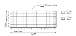
- a slot structure in which a control channel and a data channel are time division multiplexed (TDM) is considered in the fifth generation new RAT.
- the hatched region indicates a transmission region of a DL control channel (eg, PDCCH) carrying DCI
- a black part shows a transmission region of an UL control channel (eg, PUCCH) carrying UCI.
- DCI is control information delivered to the UE by the gNB
- the DCI is UL specific information such as information on cell configuration that the UE needs to know, DL specific information such as DL scheduling, and UL grant. Information and the like.
- the UCI is control information delivered from the UE to the gNB, and the UCI may include a HARQ ACK / NACK report on DL data, a CSI report on a DL channel state, and a scheduling request (SR).
- SR scheduling request
- the symbol regions from symbol index 1 to symbol index 12 may be used for transmission of a physical channel (eg, PDSCH) that carries downlink data, and may be used for transmission of a physical channel (eg, PUSCH) that carries uplink data.
- a physical channel eg, PDSCH
- PUSCH physical channel
- DL transmission and UL transmission are sequentially performed in one slot, and transmission / reception of DL data and reception / transmission of UL ACK / NACK for the DL data are performed in the one slot.
- a time gap is required for a gNB and a UE to switch from a transmission mode to a reception mode or a process of switching from a reception mode to a transmission mode.
- some OFDM symbols at the time of switching from DL to UL in the slot structure are configured as a guard period (GP).
- the DL control channel is TDM and the data channel, and the control channel, PDCCH, is spread over the entire system band and transmitted.
- the bandwidth of a system is expected to reach at least 100 MHz, which makes it difficult to spread the control channel over the entire band.
- Monitoring the entire band for downlink control channel reception for the UE to transmit / receive data may impair battery consumption and efficiency of the UE. Therefore, in the present invention, the DL control channel may be transmitted by being localized or distributed in the system band, that is, some frequency bands in the channel band.
- the basic transmission unit is a slot.
- the slot duration consists of 14 symbols with a normal cyclic prefix (CP) or 12 symbols with an extended CP.
- the slot is also scaled with time as a function of the subcarrier spacing used. That is, as the subcarrier spacing increases, the slot length becomes shorter. For example, if the number of symbols per slot is 14, if the number of slots in the frame of 10 ms is 10 for the 15 kHz subcarrier spacing, the number is 20 for the 30 kHz subcarrier spacing and 40 for the 60 kHz subcarrier spacing. The larger the subcarrier spacing, the shorter the OFDM symbol length.
- the number of OFDM symbols in a slot depends on whether it is a normal CP or an extended CP and does not depend on the subcarrier spacing.
- the actual sampling times for subcarrier intervals of 30 kHz, 60 kHz, and 120 kHz are 1 / (2 * 15000 * 2048) seconds, 1 / (4 * 15000 * 2048) seconds, and 1 / (8 * 15000 * 2048) seconds, respectively. Will be.
- the fifth generation mobile communication system which is recently discussed, considers using a high frequency band, that is, a millimeter frequency band of 6 GHz or more, to transmit data while maintaining a high data rate to a large number of users using a wide frequency band.
- 3GPP uses this as the name NR, which is referred to as NR system in the present invention.
- the millimeter frequency band has a frequency characteristic that the signal attenuation with the distance is very rapid due to the use of a frequency band too high. Therefore, NR systems using bands of at least 6 GHz or more narrow beams that solve the problem of reduced coverage due to abrupt propagation attenuation by collecting and transmitting energy in a specific direction rather than omnidirectionally to compensate for abrupt propagation characteristics. narrow beam) transmission scheme.
- narrow beam narrow beam
- the wavelength is shortened to allow the installation of a plurality of antenna elements in the same area.
- a total of 100 antenna elements can be installed in a two-dimension arrangement in 0.5 lambda (wavelength) intervals on a panel of 5 by 5 cm.
- mmW it is considered to use a plurality of antenna elements to increase the beamforming gain to increase coverage or to increase throughput.
- a beamforming scheme in which a base station or a UE transmits the same signal by using a phase difference appropriate to a large number of antennas is mainly considered.
- Such beamforming methods include digital beamforming that creates a phase difference in a digital baseband signal, analog beamforming that uses a time delay (ie, cyclic shift) in a modulated analog signal to create a phase difference, digital beamforming, and an analog beam.
- Having a transceiver unit (TXRU) to enable transmission power and phase adjustment for each antenna element enables independent beamforming for each frequency resource.
- the millimeter frequency band should be used by a large number of antennas to compensate for rapid propagation attenuation, and digital beamforming is equivalent to the number of antennas, so RF components (eg, digital-to-analog converters (DACs), mixers, power Since an amplifier (power amplifier, linear amplifier, etc.) is required, there is a problem in that the cost of a communication device increases in order to implement digital beamforming in the millimeter frequency band. Therefore, when a large number of antennas are required, such as the millimeter frequency band, the use of analog beamforming or hybrid beamforming is considered.
- DACs digital-to-analog converters
- the analog beamforming method maps a plurality of antenna elements to one TXRU and adjusts the beam direction with an analog phase shifter.
- Such an analog beamforming method has a disadvantage in that only one beam direction can be made in the entire band and thus frequency selective beamforming (BF) cannot be performed.
- Hybrid BF is an intermediate form between digital BF and analog BF, with B TXRUs, which is fewer than Q antenna elements.
- B TXRUs which is fewer than Q antenna elements.
- the direction of beams that can be simultaneously transmitted is limited to B or less.
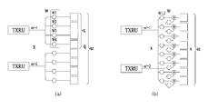
- FIG. 5 shows examples of a connection scheme of a TXRU and an antenna element.
- 5 (a) shows how a TXRU is connected to a sub-array. In this case the antenna element is connected to only one TXRU.
- 5 (b) shows how the TXRU is connected to all antenna elements. In this case the antenna element is connected to all TXRUs.
- W represents a phase vector multiplied by an analog phase shifter. That is, the direction of analog beamforming is determined by W.
- the mapping between the CSI-RS antenna port and the TXRUs may be 1-to-1 or 1-to-multi.
- digital beamforming processes the digital baseband signal to be transmitted or received so that multiple beams can be used to transmit or receive signals simultaneously in multiple directions, while analog beamforming can transmit or receive signals. Since beamforming is performed in a modulated state of the received analog signal, the signal cannot be simultaneously transmitted or received in multiple directions beyond the range covered by one beam.
- a base station communicates with a plurality of users at the same time by using a broadband transmission or a multi-antenna characteristic.
- a base station uses analog or hybrid beamforming and forms an analog beam in one beam direction, due to the characteristics of analog beamforming Only users within the same analog beam direction can communicate.
- the RACH resource allocation and resource utilization scheme of the base station according to the present invention to be described later is proposed to reflect the constraints caused by the analog beamforming or hybrid beamforming characteristics.
- FIG. 6 abstractly illustrates a hybrid beamforming structure in terms of a transceiver unit (TXRU) and a physical antenna.
- TXRU transceiver unit
- analog beamforming refers to an operation in which the RF unit performs precoding (or combining).
- the baseband unit and the RF unit perform precoding (or combining), respectively, which reduces the number of RF chains and the number of D / A (or A / D) converters.
- the hybrid beamforming structure may be represented by N TXRUs and M physical antennas.
- the digital beamforming for the L data layers to be transmitted at the transmitting end can be represented by an N-by-L matrix, and then the converted N digital signals are converted into analog signals via TXRU and then into an M-by-N matrix.
- the expressed analog beamforming is applied.
- the number of digital beams is L
- the number of analog beams is N.
- the base station is designed to change the analog beamforming on a symbol basis, so that a direction for supporting more efficient beamforming for a UE located in a specific area is being considered.
- N TXRUs and M RF antennas are defined as one antenna panel
- the NR system considers to introduce a plurality of antenna panels to which hybrid beamforming independent of each other is applicable.
- the analog beams advantageous for signal reception may be different for each UE, and thus, the base station is applied to at least a synchronization signal, system information, and paging in a specific slot or subframe (SF).
- a beam sweeping operation is considered in which a plurality of analog beams to be changed symbol by symbol so that all UEs have a reception opportunity.
- FIG. 7 is a diagram illustrating a beam sweeping operation for a synchronization signal and system information during downlink transmission.
- a physical resource or a physical channel through which system information of the New RAT system is broadcasted is referred to as a physical broadcast channel (xPBCH).
- xPBCH physical broadcast channel
- analog beams belonging to different antenna panels may be simultaneously transmitted in one symbol, and to measure a channel for each analog beam, as shown in FIG.
- a method of introducing Beam RS (BRS), which is a reference signal (RS) transmitted for a single analog beam has been discussed.
- the BRS may be defined for a plurality of antenna ports, and each antenna port of the BRS may correspond to a single analog beam.
- a synchronization signal or a xPBCH may be transmitted for all the analog beams included in the analog beam group so that any UE can receive them well.
- NR 8 illustrates a cell of a new radio access technology (NR) system.
- NR new radio access technology
- a method in which a plurality of TRPs constitute one cell is discussed, unlike one base station in a conventional wireless communication system such as LTE.
- the cell is configured, even if the TRP serving the UE is changed, seamless communication is possible, and thus, mobility management of the UE is easy.
- PSS / SSS is transmitted omni-direction, whereas signals such as PSS / SSS / PBCH are rotated omg-directionally by the gNB applying mmWave.
- a method of beamforming a beam and transmitting the beam is considered.
- transmitting / receiving a signal while rotating the beam direction is referred to as beam sweeping or beam scanning.
- beam sweeping refers to transmitter side behavior
- beam scanning refers to receiver side behavior, for example, assuming that gNB can have up to N beam directions, PSS / for each of N beam directions, respectively.
- Transmit signals such as SSS / PBCH ie, gNB transmits synchronization signals such as PSS / SSS / PBCH for each direction while sweeping directions that it may have or want to support, or gNB has N beams
- PSS / SSS / PBCH may be transmitted / received for each beam group, where one beam group may include one or more beams.
- a signal such as PSS / SSS / PBCH transmitted in the same direction may be defined as one SS block, and a plurality of SS blocks may exist in one cell.
- SS block division SS block index may be used, for example, when PSS / SSS / PBCH is transmitted in 10 beam directions in one system, PSS / SSS / PBCH in the same direction may constitute one SS block. It can be understood that there are 10 SS blocks in the system, and in the present invention, the beam index may be interpreted as an SS block index.
- the NR system does not define a common reference signal (CRS). Therefore, in the NR system, for neighbor cell measurement, instead of CRS, a Synchronization Signal Block (SSB) basically composed of PSS / SSS / PBCH, and additionally CSI-RS (Channel State Information) Neighbor cell measurement is performed using a reference signal.
- SSB Synchronization Signal Block
- CSI-RS Channel State Information
- the synchronization signal is transmitted with a certain period, but in NR, it may be set to have various SSB transmission periods to support various operation methods of the base station.
- the UE acquires the existence of the cell and the SSB reception timing by using the SSB, and measures the RSRP for the SSB at a predetermined time based on the obtained information.
- the UE does not know the transmission period of the SSB, after measuring the RSRP for all possible SSB transmission period, it is necessary to predict the transmission period of the SSB, or select the RSRP to be used as a measurement value from the measured RSRP There is a problem of increasing power consumption.
- the UE receives the SSB, detects the cell and finds the timing information of the cell, and then the timing information of the cell Based on the transmission period of the and SSB, by measuring the RSRP only at the time when the SSB is transmitted, it is possible to reduce the power consumption (power consumption).
- the parameters related to the measurement should include the transmission period of the SSB. That is, RSRP measurement of a neighbor cell for supporting mobility of the UE in the NR system cannot operate at any time set by the UE, and neighbor cell measurement from the base station in the call setup step. It is necessary to receive a parameter for measurement, and the parameter for measuring the neighbor cell may include a parameter related to the SSB configuration, including the SSB transmission period.
- At least one SSB must be assigned to a Component Carrier and the SSB must be placed within a preferred frequency position defined by the channel raster.
- the system bandwidth is larger than the UE minimum bandwidth, a plurality of SSBs may be allocated to the wideband component carrier, and in this case, only one SSB may be sufficient within the UE minimum bandwidth for initial access. In other words, multiple SSBs do not necessarily need to be located within the UE minimum bandwidth.
- the maximum number of SSBs that can be transmitted in the CC may be defined as [UE minimum bandwidth defined in system bandwidth / frequency band]. However, even in this case, only the maximum number of SSBs that can be allocated in the CC is defined, and the actual number of SSBs allocated can be freely configured by the gNodeB.
- the plurality of SSBs do not need to be broadcast to the UE, and the SSB frequency position in the bandwidth part (BWP) performs connection establishment or connection reconfiguration.
- UE-specific signaling may be signaled while performing the operation.
- At least one BWP including the SSB is changed in frequency or measurement gap due to frequency retuning or measurement gap configuration. In addition, it should be allocated to support mobility of the UE.
- a network may transmit a plurality of SSBs within a wideband component carrier to provide a wide bandwidth, but may not support all of the wide bandwidth and may support only a partial bandwidth.
- a UE capable of supporting a wide bandwidth may detect a plurality of SSBs and measure RSRP using all of the detected SSBs.
- it may be sufficient to use only one SSB among the plurality of SSBs at the cell level. Rather, using one SSB is advantageous in terms of power consumption and UE complexity.
- the UE may need to measure the RSRP of all SSBs at different frequencies.
- the measurement capability of the UE should be defined for each CC, and the UE should be determined for each neighboring cell during a predefined duration. The same number of RSRPs can be measured.
- the UE During the initial connection, the UE must camp on to search for the cell and obtain information of the SSB to support mobility to be applied to all cells within the carrier frequency.
- the SSB information may include the period of the SSB, the number of actual transmitted transmission signal blocks (ATSS) or the time location of the SSB.
- the information of the SSB should be broadcasted through PBCH or RMSI.
- the frequency position at which the SSB is transmitted should be signaled to the UE entering the IDLE mode after completion of call release.
- the gNodeB when the UE enters the connected mode and the BWP in the component carrier is configured, the gNodeB has information of the SSB for the serving cell, such as the presence of the SSB, the period of the SSB, information on the ATSS, and the like. Can be provided to the UE through a Connection Configuration message.
- information of the SSB for neighbor cells may also be included in the Connection Configuration message.
- the network should inform the UE performing the initial access that no system information is transmitted through the PBCH.
- RMSI Remaining Minimum System Information
- SIB1 System Information Block 1
- SSB may be located at a frequency that does not perform the initial connection.
- SSS is used for downlink-based RRM measurement and there is still a discussion about whether PBCH DM-RS can be additionally used for RRM measurement.
- 9 shows RSRP accuracy based on SSS of 2.16 MHz and PBCH of 4.32 MHz, at 15 KHz subcarrier spacing. As can be seen in FIG. 9, an SSS of 2.16 MHz provides adequate RSRP accuracy for RRM measurements.
- the UE since the network can increase the transmit power of the SSS for cell coverage expansion, the UE must know the power offset of the PBCH DM-RS for the SSS in order to use the PBCH DM-RS for RRM measurement. do.
- the details of the power offset such as whether the power boosting of the SSS is applied, how much power is allocated to the SSS, and so on, depends on the cell environment and may vary from cell to cell, so that one power offset value is equal to the same frequency.
- the PBCH DM-RS can be used for RRM measurements only if it can be applied to all cells in the cell. Otherwise, the performance requirements should be determined based only on SSS-based measurements.
- the power offset of the PBCH DM-RS is applied to the default value set according to the frequency band in the connected mode, or the cell list of the measurement setup is used. Can be configured per cell through For example, the power offset of the PBCH DM-RS may be applied to each cell included in the cell list, and a default value set according to the frequency band may be applied to other cells not included in the cell list.
- neighbor cell measurement in the connected mode is performed for inter-cell interference coordination. That is, the UE may measure the interference for each cell or beam, and use neighbor cell measurement to report to the base station that a specific cell or beam affects the interference. Based on the beam-by-beam interference measurement, the UE may derive the interference level per cell.
- beam level interference measurement it is necessary to determine whether to perform beam level cell interference measurement based on SSB-RSRP per cell in connected mode or to measure beam level cell interference based on CSI-RS-RSRP. There is.
- the UE In order to support cell selection / reselection of the UE, it is necessary to define a method for calculating cell quality. Since there is no single RSRP value representing cell quality in a multi-beam environment, the UE should calculate cell quality based on certain criteria. Of course, in a cell transmitting one SSB, the SSB-RSRP may indicate cell quality. However, for a cell transmitting multiple SS blocks, the UE should use RSRPs of multiple SSBs to calculate cell quality, and similarly, in a situation where multiple CSI-RSs exist, the UE may When configuring CSI-RSs to support, the UE should calculate cell quality using multiple CSI-RS RSRPs in connection mode.
- the time average of the downlink reference signal having the best reception value in each measurement instance may be calculated based on Equation 1 below.
- the mean does not mean the mean for the spatial domain, such as multiple SSBs or multiple CSI-RSs, in a given instance.
- the UE selects the best SSB-RSRP or CSI-RS RSRP in each measurement instance and calculates the average of the best SSB RSRPs or CSI-RS RSRP values during the average time window.
- the SSB transmission period of the serving cell and the SSB transmission period of the adjacent cell are different from each other. That is, although SSB sparse transmission is applied for low mobility environment and efficient resource use, SSB of serving cell can be used for various purposes such as time and frequency tracking, radio link monitoring, beam management, and beam recovery. It may be used for the purpose, and the SSB transmission period of the serving cell should be kept short regardless of the SSB transmission period of the neighbor cell, so that the UE can operate more stably in the cell.
- the macro cell can transmit the SSB in a short period while focusing on mobility, and the small cell can transmit the SSB in a long period by focusing on high system throughput.
- multiple SSB transmission periods can be considered in two aspects: cell detection and mobility measurement.
- the UE may attempt to accumulate the PSS correlation metric or the SSS correlation metric for improving mobility performance, regardless of one-shot detection of the SSS.
- it may be difficult to set a plurality of SSB transmission periods due to large UE complexity, and a performance difference between a case of setting a single SSB transmission period and a case of setting a plurality of SSB transmission periods may be observed.
- the UE measures the RSRP of the reference signal for the detected cell, and the RSRP value is filtered at L1 and / or L3. During the filtering operation, it may happen that the RSRP of some cells is not measured due to very low value or very low quality. In this case, the UE should decide whether the measurement for the cell should be continued.
- the network may provide the SSB transmission period for each cell included in the cell list of the measurement configuration.
- the basic transmission period of the SSB according to the frequency may be provided by the network for cells not in the cell list.
- base stations may be arranged in various forms in one frequency band, and various types of systems may be configured for each base station.
- the base station to which the UE is connected and the base station to which the UE is not connected may perform system optimization through different configurations.
- the base station to which the UE is connected may increase the transmission rate of the Synchronization Signal Block (SSB) to allow the UE to operate stably, and the base station to which the UE is not connected may lower the transmission rate of the SSB or do not transmit the SSB. Power consumption of the base station can be reduced.
- SSB Synchronization Signal Block
- a base station supporting a high moving speed of the UE and a base station supporting a low moving speed of the UE coexist in one frequency band. That is, the system frequency efficiency can be maximized by shortening the transmission period of the SSB when supporting a high moving speed and by increasing the transmission period of the SSB when supporting a low moving speed.
- the base station can secure a variety for cell operation, there is an advantage that can increase the frequency efficiency or power consumption of the base station as needed.
- the base station when accessing a system supporting a plurality of SSB periods (periodicity) from the UE perspective, if there is no additional information, it may be necessary to perform the following operation.
- the UE acquires information on at what time the signal transmitted from the PSS was received, and obtains a time point at which the SSS is expected to be received using the time information on the received time point. At the expected time point, the existence of the cell is checked through a correlation value with the SSS sequence.
- the UE measures the RSRP using the SSS or PBCH of the SSB according to the SSB transmission period for the detected cell. However, when a plurality of SSB transmission periods are set, the UE measures an RSRP value based on any one of the SSB transmission periods.
- RSRP is measured assuming a short SSB transmission period
- a high receiver complexity is required to determine the cause of RSRP deterioration, or SSB signal detection is performed. It can reduce the reliability of, and can cause high power consumption because RSRP is measured with short SSB transmission period for all cells.
- RSRP is measured assuming a long SSB transmission period
- the RSRP is measured assuming a long SSB transmission period even for a cell having a short SSB period, thereby degrading the mobility performance directed by the system. You can. That is, in the case of a system supporting multiple SSB periods, even if the system informs the UE of the SSB period set by the system, the UE connected to the system does not reduce power consumption. Or the receiver complexity will increase significantly.
- the present invention proposes a method of designating an SSB transmission period for each cell in a system supporting a plurality of SSB transmission periods.
- the base station provides the UE with a list of major cells around the target cell or sets up a call through system information in the initial selection or cell selection / re-selection step of IDLE mode.
- the UE provides a list of major cells around the target cell through a measurement configuration message.
- the step of providing a cell list information on the SSB transmission period for each cell may be transmitted together.
- the UE measures RSRP only when the SSB of the cell is transmitted in the step of measuring RSRP for each cell after the cell is detected using the SSB transmission period information for each cell.
- the measured RSRP information may be filtered or reported as it is to a higher layer, and an RRM measurement process may be performed. Through this process, unnecessary power consumption of the UE can be prevented and the complexity of the UE can be reduced.
- the message size of the cell list may be too large.
- the SSB signal of a cell that is not intentionally included in the cell list, that is, not present around the target cell may be detected, and the signal of the SSB may be measured with the best reception quality. .
- the default SSB transmission period may be determined as the longest SSB transmission period or the shortest SSB transmission period among SSB transmission periods allocated for each cell, which may be defined in a standard document. .
- the longest SSB transmission period is determined as the default SSB transmission period, since RSRP is measured reliably, there is little concern about ping-pong which is repeatedly measured at high and low values of RSRP. .
- the detected cell is a cell that supports a high moving speed, performance for high mobility may be degraded.
- the shortest SSB transmission period is determined as the default SSB transmission period, performance for high mobility for a cell supporting high mobility is obtained, but the SSB transmission is performed using a long SSB transmission period. Since a ping-pong phenomenon for RSRP of a cell to be transmitted may occur, stable handover for the cell may not be performed.
- the base station may directly set the default SSB transmission period (periodicity) when the base station transmits the SSB transmission period (periodicity) for each cell in accordance with the environment that the system is to secure stably.
- an embodiment for reducing power consumption due to neighbor cell measurement may be additionally considered. That is, in a synchronous network or a system in which SSB transmission of all cells within a certain duration is guaranteed, the measurement duration and timing offset along with the SSB transmission period are determined. I can tell you.
- the timing offset may indicate a location where a measurement duration exists with respect to the system time when the SSB transmission period is given.
- the SSB measurement time length determined according to the SSB transmission period, measurement duration, and timing offset may be defined as an SSB measurement window, and the UE may detect cell detection and RSRP measurement only within the SSB measurement window. Perform measurement.
- the same timing offset value and measurement interval are applied to cells included in the cell list and cells not included in the cell list.
- the SSB measurement window for SSB measurement can be determined.
- the SSB transmission period is set differently for each cell, even though the timing offset value and the measurement interval are the same, different SSB measurement windows can be calculated for each cell, and the UE according to the calculated SSB measurement window, SSB measurement can be performed for each cell.
- the information about the timing offset and the measurement interval may be indicated together with information on the SSB transmission period for the cells included in the cell list, or information about the basic SSB transmission period for the cells not included in the cell list. Can be indicated together.
- a UE may include a cell list, which is a list of major neighbor cells around a target cell, from a base station, and a first cell for neighbor cells included in the cell list.
- Information on the SSB transmission period is received (S1001).
- the second SSB transmission period (that is, the basic SSB transmission period) for the cells not included in the cell list, and the measurement interval And timing offset information (S1003).
- the measurement interval and the timing offset information may be transferred together with the information about the cell list and the first SSB transmission period.
- the UE sets an SSB measurement window for measuring RSRP of the SSB for each cell based on the first SSB transmission period, the second SSB transmission period, the measurement interval, and the timing offset (S1005).
- SSB measurement is performed for each cell based on the SSB measurement window (S1007).
- the embodiment described with reference to FIG. 10 assumes that both the SSB measurement window for cells included in the cell list and the SSB measurement window for cells not included in the cell list are set based on the same measurement interval and timing offset.
- the measurement interval and timing offset for cells included in the cell list and cells not included in the cell list may be different from each other.
- SSB measurement windows are defined for the entire system, and each cell is used to measure RSRP in the SSB measurement window set over the entire time. It is also possible to specify the SSB measurement window sub-set, which will be used. In other words, a plurality of SSB measurement windows are determined using a plurality of SSB transmission periods, and a plurality of SSB measurement windows determined using the plurality of SSB transmission periods are defined as SSB measurement window sets.
- the plurality of SSB measurement windows included in the SSB measurement window set are divided into one or more SSB measurement window sub-sets, each of the SSB measurement window subsets is designated for each cell, and each The cell may measure RSRP within a subset of SSB measurement windows set to it.
- cell 1 can measure RSRP within a subset of SSB measurement windows consisting of SSB measurement windows 1, 5 and 9.
- Cell 2 may be designated to measure RSRP within a SSB measurement window subset of SSB measurement windows 2, 6, and 10.
- RSRP can be measured using the SSB measurement window subset for cells not included in the cell list.
- the same measurement duration and offset may be used as in the above-described example.
- the above-described embodiment may be applied to RRM measurement using a reference signal other than SSB.
- the above-described embodiment can be applied to RRM measurement using CSI-RS.
- the NR system transmits signals using a plurality of beams in which one cell forms a high beam gain, thereby increasing coverage in a high frequency band or obtaining high throughput in the same location.
- the SSB is also time-divisionally transmitted in a plurality of beam directions in order to expand coverage.
- a UE connected to a specific cell needs to measure a reception power level of an adjacent cell in order to support mobility of a communication system, and uses an SSB as a basic signal for reception power measurement in an NR system.
- the UE knows the existence of the cell using the SSB, and unless otherwise indicated, the UE measures the received power for the SSB at all the transmittable positions defined in the standard, that is, the candidate SSB position, for the detected cell, and has the highest By using the RSRP of the SSB having the reception power, it is defined as the RSRP of the cell.
- up to 64 SSBs can be transmitted, and a UE operating in a band of 6 GHz or more detects one cell, and then up to 64 candidate SSB positions regardless of the number of ATSSs of the cell. By measuring the received power in, calculates the RSRP of the cell, and if necessary report it to the base station.
- RSRP of neighbor cells must also be measured, and thus, a process of measuring reception power may be performed even for an SSB that is not actually transmitted. That is, a case in which the UE performs an unnecessary operation may occur, which may increase the complexity of the UE because it not only increases power consumption of the UE, but also requires measuring RSRP of a large number of SSBs.
- the base station it is necessary for the base station to additionally transmit information about the number of ATSS or the location of the ATSS to the UE.
- the UE receives information on which SSB is actually transmitted to the ATSS among a plurality of transmittable SSBs (that is, candidate SSBs) in the neighbor cell, and RSRP only for the ATSS. By measuring the power consumption of the UE can be reduced.
- the UE in order to reduce the complexity and power consumption of the UE, it is necessary to inform the UE of the index of the ATSS actually transmitted among the transmittable SSBs.
- one cell may transmit a maximum of 64 SSBs, and which SSB of the maximum 64 candidate SSBs may be used as an ATSS may be differently set for each cell. Therefore, in order to inform ATSS information of all cells, a bitmap of up to 64 bits should be used for each cell, which causes too much signaling overhead. Therefore, in the present invention, to reduce the power consumption of the UE required in the process of measuring the reception power level of the neighboring cell, to look at the information transfer method for ATSS transmission of the cells in order to use resources efficiently.
- the SSB cannot transmit other channels such as paging message, PDSCH, etc. in the resource (RE), but the SSB can transmit but the SSB is not actually transmitted. That is, in a resource where ATSS is not transmitted, transmission of another channel may be allowed to increase frequency efficiency.
- the UE should know whether the SSB is transmitted in the corresponding resource along with information on resource mapping such as a data channel through the control channel. Therefore, the UE needs to know the information about the SSB transmission of the serving cell accurately for each SSB. Therefore, the information on the ATSS freely set and transmitted by the serving cell should be accurately informed using a bitmap of the number of bits corresponding to the maximum number of SSBs (N max, SSB ) that can be transmitted in the frequency band.
- N max, SSB maximum number of SSBs
- the information on the ATSS for the neighbor cell included in the cell list may be informed in the same manner as the serving cell.
- Nmax SSB is too large, since signaling overhead may be too large, it is preferable to configure the corresponding information in a compressed form.
- N max, SSB is defined as up to 8 in the frequency band below 6 GHz and up to 64 in the frequency band above 6 GHz. Therefore, when N max, SSB is too large, SSB is transmitted in the frequency band above 6 GHz. Can mean.
- each ATSS is used using a 64-bit full bitmap.
- signaling overhead is large, so various methods can be used as follows.
- a total of 64 candidate SSBs can be grouped into 8 SSBs, compressed into a total 8-bit bitmap, and transmitted in the form of '11000000'.
- the required number of bits is 8 bits.
- the UE since the UE receives the bitmap information of '11000000', the UE may preferentially measure the RSRP for the SSB having an index of 1 to 16 or measure the RSRP only for the SSB.
- the method of using the above-described ATSS information may be as follows.
- the base station transmits ATSS information to the UE by the above-described method
- the UE receives information about the SSB index to which RSRP should be measured first for each cell or information about the SSB index to be measured by the UE to the minimum.
- the ATSS information is used. If necessary, the UE may measure the RSRP of the SSB at another candidate SSB time position other than the SSB included in the ATSS, and if it obtains valid RSRP information at another candidate SSB time position, may report it to the base station. That is, ATSS information of a neighbor cell for measuring RSRP preferentially may not exactly match the actual ATSS.
- the base station delivers ATSS information to the UE
- the UE assumes that the base station does not transmit the SSB for the index of the SSB except for the location of the ATSS according to the ATSS information do. Therefore, RSRP measurement is not performed except for the position according to ATSS information. Through this, power consumption of the UE can be minimized.
- the above-described method may be interpreted as specifying the SSB index that does not require RSRP measurement because the SSB is never transmitted, not the position where the SSB is assumed to be transmitted.
- the default value of the applicable SSB transmission for cells not included in the cell list is not information transmitted for each cell, like the serving cell, the basic value is transmitted as information specifying each SSB, such as a full bitmap, or as ATSS information in a compressed form as described above. Can transmit
- the cell-specific information on the cell list is omitted and the UE sets the aforementioned default value.
- (default value) may be used for SSB selection in which priority is applied in RSRP measurement for all cells except the serving cell.
- the UE uses ATSS information of the serving cell as ATSS information for determining RSRP measurement priority of the neighbor cell. Meanwhile, the base station may directly instruct to insert an additional 1 bit of information to use the ATSS information of the serving cell as the ATSS information for the neighboring cell.
- a default value may be used according to the method defined in Examples 1-1 to 1-2.
- ATSS information is primarily transmitted through system information in order for the UE to use RSRP measurement of a neighbor cell or as RE mapping information of a paging message in an IDLE mode.
- ATSS information may be transmitted as an RRC message for use as an information for RE mapping or a more accurate information for RSRP measurement in a call configuration process, and the ATSS information is transmitted through system information. It may take precedence over ATSS information received through. That is, even if the ATSS information is received through the system information, after receiving the ATSS information through the RRC message, the UE performs RSRP measurement of the SSB using the ATSS information received through the RRC message, or RE mapping information. Can be obtained. If call release is performed, information received through system information may be used as ATSS information for the serving cell and the neighbor cell. That is, when the call is released, the ATSS information received through the system information is given priority over the ATSS information received through the RRC message.
- a system operating in a high frequency band such as mmWave may use beamforming at the receiving end as well as the transmitting end.
- the beamforming of the receiving end is generally used to measure the quality of the received signal for mobility support along with the receiving process of the data channel or the control channel.
- UEs operating in the beamforming environment of the receiving end may have different antenna configuration or analog beamforming characteristics, depending on the implementation manner of the UE. In this case, if the same RSRP definition as LTE can be used, different RSRP values can be measured and reported to the base station for each UE due to different antenna settings.
- the base station that has received the communication information such as RSRP and the location information from the UE, the location information and communication quality information in its own cell optimization and cell configuration It can be utilized.
- the communication information such as RSRP and the location information from the UE
- the location information and communication quality information in its own cell optimization and cell configuration It can be utilized.
- the base station since a large number of UEs use omni-directional antennas, measurement errors or antenna characteristic differences due to UE shapes mainly cause variation of RSRP according to location.
- the antenna configuration or the analog beamforming characteristic is different for each UE, there is a problem in that a bias for the RSRP is formed along with the variation of the RSRP, which causes a large error in the network performing cell optimization. There is a problem that can be caused.
- the present invention proposes a method of reflecting different antenna settings according to UE in defining RSRP.
- the RSRP measurement may be performed in the UE or the UE may report to the base station so that the base station may reflect the RSRP value to beamforming.
- the system defines a reference antenna configuration of the UE and defines it in a standard, or the base station delivers the reference antenna configuration to the UE.
- the number of antenna elements constituting one antenna port may be set based on four arranged in a line, and the base station may transmit the same to the UE.
- the UE and the base station may perform the following method to reflect the gain due to the antenna setting in the RSRP value.
- the UE reports to the base station a predicted difference value between the RSRP value of the reference antenna configuration and the RSRP value according to the current reception antenna configuration in the call setup step or the MDT setup step. Thereafter, the UE measures and reports the RSRP value according to the current antenna configuration to the base station, and the base station obtains the RSRP REF value by applying the reported RSRP value and a previously reported difference value.
- the UE reports the current receiving antenna configuration, such as the number of antenna elements per antenna port, to the base station in the call setup phase or the MDT setup phase. Thereafter, the UE measures and reports the RSRP value according to the current reception antenna setting to the base station, and the base station obtains the RSRP REF value by reflecting the reported reception antenna setting of the UE. At this time, the UE reports the reception antenna setting for each frequency band to the base station, and the base station can calculate the final RSRP value by reflecting the reception antenna setting for each frequency band for each frequency band in the inter-frequency measurement results. have.
- CSI-RS When measuring RSRP by using CSI-RS in inter-frequency measurement mode, CSI-RS cannot self-synchronize.
- the system timing information for the CSI-RS should be measured based on the system timing information.
- cells in the target frequency band transmit resources for which the CSI-RS is mapped and all candidate SSBs defined for each frequency band in order to secure freedom in resource operation. It can be transmitted at a time other than the SS burst set, which is a time duration.
- the measurement gap allocation method and resource allocation method for the UE to perform inter-frequency measurement in the above-described case will be described.
- the base station sets a measurement gap for performing inter-frequency measurement, and a measurement gap for SSB and a CSI-RS for CSI-RS RSRP measurement.
- the UE may acquire timing information on the detected cell by performing an operation for cell detection in a measurement gap for SSB.
- the UE uses a measurement gap for CSI-RS for CSI-RS RSRP measurement for the detected cell.
- the measurement gap for the SSB and the measurement gap for the CSI-RS may have the same period, may have different periods, or may overlap.
- the interruption with the serving cell may occur frequently, so the measurement gap for SSB ) And other ways to set the measurement gap for the CSI-RS.
- the measurement gap for the SSB (measurement gap) is set to the UE, and the UE acquires the cell detection using the SSB, timing information of the detected cell and SSB RSRP for the detected cell based on the measurement gap (measurement gap)
- the base station informs the UE of a measurement gap for the CSI-RS. Set it.
- the UE measures the CSI-RS RSRP using cell information obtained through cell detection through the SSB and a measurement gap for the CSI-RS, and reports it to the base station.
- the base station transmits signals having different beam widths or signals transmitted in different beam directions in the same symbol.
- the same symbols as SSBs spatially QCLed for CSI-RS Can be allocated within the area.
- the time resource information of the CSI-RS only needs to convey information about a symbol where the CSI-RS is located in the specific SSB.
- this special type of measurement gap allocation method there is no need to set a measurement gap for SSB and a measurement gap for CSI-RS, and a common measurement gap. You only need to allocate gaps.
- information on time resources generally includes SFN, frame index, slot index, and OFDM. It is based on absolute system time, such as symbol index.
- the system time can be obtained by decoding the PBCH of the target cell, which greatly increases the complexity of the UE.
- the UE does not perform PBCH decoding and performs CSI-RS.
- the location of the resource is known.
- the CSI-RS resource information includes the time axis position of the SSB in the measurement gap for SSB and the time of the CSI-RS in the measurement gap for CSI-RS, which are commonly applied to the target cell or all cells. Information about the relative difference in axis position is communicated to the UE.
- CSI-RS is used for various purposes. For example, it may be used to determine downlink MCS and resource allocation or to manage downlink beam and L3 mobility. The characteristics of CSI-RS for channel quality measurement are different from those for beam management / mobility. Meanwhile, configuration of the CSI-RS for L3 mobility may be reused for setting the CSI-RS for beam management. That is, the CSI-RS configuration for mobility support and the CSI-RS configuration for beam management may be the same.
- CSI-RS As a basic characteristic of CSI-RS to support L3 mobility, it should be determined whether CSI-RS is periodic or aperiodic. Triggering the CSI-RS in a non-periodic manner incurs downlink control overhead and it is not easy to dynamically trigger adjacent cell CSI-RS transmission for L3 mobility. Therefore, in consideration of UE operation for L3 mobility, the CSI-RS should be transmitted periodically.
- the transmission period of the SSB may be selected from ⁇ 5ms, 10ms, 20ms, 40ms, 80ms, 160ms ⁇ .
- the CSI-RS may be used as a complementary reference signal in order for SSB to have long periodicity and to support stable mobility at the granular beam level. Therefore, the period of the CSI-RS need not be long, and the period of the CSI-RS for the RRM measurement may be ⁇ 5ms, 10ms, 20ms ⁇ .
- the CRS is used for the RRM measurement, and the measurement bandwidth of the CRS is set separately because the system bandwidth of the neighboring cell may be different from the system bandwidth of the serving cell.
- setting the measurement bandwidth of the CRS separately does not mean that the UE does not completely use the CRS because the UE uses the measurement bandwidth only to meet the minimum performance requirements in order to minimize the complexity of the UE.
- the transmission bandwidth of the CSI-RS to be applied to all neighbor cells may be configured through a UE dedicated RRC configuration message.
- the information conveyed through the UE-specific RRC configuration message means the maximum allowable measurement bandwidth, and how wide the bandwidth of the CSI-RS is used for actual measurement purposes is an implementation issue.
- the subcarrier spacing of the CSI-RS is based on the data channel subcarrier spacing to facilitate resource allocation, while the data channel subcarrier spacing of the neighbor cell is the data channel subcarrier spacing of the serving cell. May not be the same as Accordingly, the subcarrier spacing of the CSI-RS may be configured semi-statically per cell or per frequency through an RRC configuration message. In particular, the subcarrier spacing of the CSI-RS is preferably set for each frequency in terms of reducing the complexity of the UE.
- NR For CSI-RS transmission for beam management, NR supports sub-time units having a size equal to or smaller than an OFDM symbol in reference numerology.
- sub-time unit transmission among some candidates for sub-time unit transmission to receive beam sweeping or transmit beam sweeping in OFDM symbols, Large Subcarrier Spacing not only results in low spectral efficiency due to guard subcarriers, There is a problem that the complexity of the implementation is increased because it requires additional receive filters for different FFT sizes and different numerologies. Therefore, IFDMA may be more suitable for transmission in sub time units.
- the CSI-RS may be used in addition to the SSB for downlink measurement. That is, there may be a plurality of SSBs for measuring a plurality of SB-RSRPs, and a plurality of CSI-RSs may be set for each of the plurality of SSBs.
- the connected mode since the UE tracks the CSI-RS based RSRP in addition to the SSB-RSRP, the relationship between the SSB-RSRP and the CSI-RS based RSRP can be usefully used for downlink measurement.
- the CSI-RS may be associated with the SSB. That is, the UE may first detect the SSB and obtain time / frequency synchronization to estimate the time / frequency synchronization of the CSI-RS from the SSB obtained for each cell.
- the bandwidth of the SSB is wider than the bandwidth of the CSI-RS, and several CSI-RSs may exist within the width of the SSB, part of the spatial information may be obtained from the SSB.
- the CSI-RS set may be defined within the beam width of a specific SSB, and such CSI-RS set information should be provided to the UEs.
- the CSI-RS may not be associated with a particular SSB.
- the content of the measurement report may be different.
- a CSI-RS RSRP based measurement event if the CSI-RS is associated with the SSB, the SSB RSRP should be reported along with the CSI-RS RSRP. If the CSI-RS is not associated with the SSB, it is not necessary to report the SSB-RSRP when the UE reports the CSI-RS RSRP. In addition, when the CSI-RS resource is not configured for a specific cell, only SSB-RSRP for the cell may be reported.
- the network may provide CSI-RS configuration per cell and neighbor cell list. In order to reduce signaling overhead, the number of neighbor cell lists or CSI-RSs may be limited. In order to prevent periodic broadcasting of CSI-RS configuration, CSI-RS configuration information should be provided through UE-specific RRC signaling. If the UE detects the SSB of the cell that does not exist in the neighbor cell list or the CSI-RS is not assigned to the UE, the UE may request CSI-RS configuration for the cell.
- FIG. 11 is a block diagram illustrating components of a transmitter 10 and a receiver 20 for carrying out the present invention.
- the transmitter 10 and the receiver 20 are radio frequency (RF) units 13 and 23 capable of transmitting or receiving radio signals carrying information and / or data, signals, messages, and the like, and in a wireless communication system.
- the device is operatively connected to components such as the memory 12 and 22, the RF unit 13 and 23, and the memory 12 and 22, which store various types of information related to communication, and controls the components.
- a processor (11, 21) configured to control the memory (12, 22) and / or the RF unit (13, 23), respectively, to perform at least one of the embodiments of the invention described above.
- the memories 12 and 22 may store a program for processing and controlling the processors 11 and 21, and may temporarily store input / output information.
- the memories 12 and 22 may be utilized as buffers.
- the processors 11 and 21 typically control the overall operation of the various modules in the transmitter or receiver. In particular, the processors 11 and 21 may perform various control functions for carrying out the present invention.
- the processors 11 and 21 may also be called controllers, microcontrollers, microprocessors, microcomputers, or the like.
- the processors 11 and 21 may be implemented by hardware or firmware, software, or a combination thereof.
- application specific integrated circuits ASICs
- DSPs digital signal processors
- DSPDs digital signal processing devices
- PLDs programmable logic devices
- FPGAs field programmable gate arrays
- the firmware or software when implementing the present invention using firmware or software, may be configured to include a module, a procedure, or a function for performing the functions or operations of the present invention, and configured to perform the present invention.
- the firmware or software may be provided in the processors 11 and 21 or stored in the memory 12 and 22 to be driven by the processors 11 and 21.
- the processor 11 of the transmission apparatus 10 is predetermined from the processor 11 or a scheduler connected to the processor 11 and has a predetermined encoding and modulation on a signal and / or data to be transmitted to the outside. After performing the transmission to the RF unit 13. For example, the processor 11 converts the data sequence to be transmitted into K layers through demultiplexing, channel encoding, scrambling, and modulation.
- the coded data string is also called a codeword and is equivalent to a transport block, which is a data block provided by the MAC layer.
- One transport block (TB) is encoded into one codeword, and each codeword is transmitted to a receiving device in the form of one or more layers.
- the RF unit 13 may include an oscillator for frequency upconversion.
- the RF unit 13 may include N t transmit antennas, where N t is a positive integer of 1 or more.
- the signal processing of the receiver 20 is the reverse of the signal processing of the transmitter 10.
- the RF unit 23 of the receiving device 20 receives a radio signal transmitted by the transmitting device 10.
- the RF unit 23 may include N r receive antennas, and the RF unit 23 frequency down-converts each of the signals received through the receive antennas to restore the baseband signal. .
- the RF unit 23 may include an oscillator for frequency downconversion.
- the processor 21 may decode and demodulate a radio signal received through a reception antenna to restore data originally transmitted by the transmission apparatus 10.
- the RF units 13, 23 have one or more antennas.
- the antenna transmits a signal processed by the RF units 13 and 23 to the outside under the control of the processors 11 and 21, or receives a radio signal from the outside to receive the RF unit 13. , 23).
- Antennas are also called antenna ports.
- Each antenna may correspond to one physical antenna or may be configured by a combination of more than one physical antenna elements.
- the signal transmitted from each antenna can no longer be decomposed by the receiver 20.
- a reference signal (RS) transmitted in correspondence with the corresponding antenna defines the antenna as viewed from the perspective of the receiver 20, and whether the channel is a single radio channel from one physical antenna or includes the antenna.
- RS reference signal
- the receiver 20 enables channel estimation for the antenna. That is, the antenna is defined such that a channel carrying a symbol on the antenna can be derived from the channel through which another symbol on the same antenna is delivered.
- the antenna In the case of an RF unit supporting a multi-input multi-output (MIMO) function for transmitting and receiving data using a plurality of antennas, two or more antennas may be connected.
- MIMO multi-input multi-output
- the RF units 13 and 23 may support receive beamforming and transmit beamforming.
- the RF units 13 and 23 may be configured to perform the functions illustrated in FIG. 3.
- the RF units 13 and 23 may also be referred to as transceivers.
- the UE operates as the transmitter 10 in the uplink and the receiver 20 in the downlink.
- the gNB operates as the receiving device 20 in the uplink and the transmitting device 10 in the downlink.
- the processor, the RF unit and the memory provided in the UE will be referred to as a UE processor, the UE RF unit and the UE memory, respectively, and the processor, the RF unit and the memory provided in the gNB will be referred to as a gNB processor, a gNB RF unit and a gNB memory, respectively.
- the gNB processor of the present invention transmits information on a first SSB transmission period for cells included in a cell list and information on a second SSB transmission period for cells not included in a cell list to the UE, and sets a preset candidate SSB. Send one or more SSBs to the UE through the regions.
- the gNB processor may transmit information on the offset and the measurement interval for the UE to measure the SSB, and if necessary, further transmit the configuration information on the CSI-RS to the UE, Accordingly, the CSI-RS may be periodically or aperiodically transmitted to the UE.
- the SSB may include PSS / SSS / PBCH, and a part of the region to which the PBCH is mapped may be used for DMRS.
- the gNB processor may control the transceiver to receive a report on the RSRP measured by the UE.
- the UE processor of the present invention receives information about a cell list and a first SSB transmission period for cells included in the cell list and information about a second SSB transmission period for cells not included in the cell list, and offsets and measurements Controls the information about the section together. Then, the SSB measurement window for each cell is set up using the information on the first and second SSB transmission periods, offsets, and measurement intervals.
- the offset and the measurement interval is equally applied to set the SSB measurement window for all cells. That is, in order to set a plurality of SSB measurement windows, the same offset and measurement interval information is used, except that the first and second SSB transmission periods are set differently for each cell or each cell group, and thus, each cell or each cell group.
- the SSB measurement window for may be set differently.
- the UE processor does not measure the RSRP of the SSB outside of the SSB measurement window, but measures the RSRP of the SSB only within the SSB measurement window.
- the UE processor measures the RSRP of the SSB using the SSS and the PBCH-DMRS among the PSS / SSS / PBCH constituting the SSB, and additionally uses the CSI-RS when receiving the CSI-RS configuration information from the base station.
- RSRP of the SSB can be measured.
- the UE processor may control to report the RSRP of the measured SSB to the gNB for each cell.
- the gNB processor or UE processor of the present invention may be configured to apply the present invention on a cell operating in a high frequency band of 6 GHz or more where analog or hybrid beamforming is used.
- SSB synchronization signal block
Abstract
본 발명은 무선 통신 시스템에서, 단말이 동기 신호 블록(Synchronization Signal Block; SSB)을 측정하는 방법을 개시한다. 특히, 본 발명은, 하나 이상의 제 1 셀들의 정보를 포함하는 셀 리스트, 상기 하나 이상의 셀들을 위한 제 1 SSB 전송 주기(periodicity) 정보 및 상기 셀 리스트에 포함되지 않은 제 2 셀을 위한 제 2 SSB 전송 주기 정보를 수신하며, 상기 제 1 SSB 전송 주기 정보를 이용하여 설정(setup)된 제 1 SSB 측정 윈도우를 기반으로 상기 하나 이상의 제 1 셀들의 SSB에 대한 RSRP(Reference Signal Received Power)를 측정하며, 상기 제 2 SSB 전송 주기 정보를 이용하여 설정(setup)된 제 2 SSB 측정 윈도우를 기반으로 상기 제 2 셀의 SSB에 대한 RSRP를 측정하는 것을 포함할 수 있다.
Description
본 발명은, 동기 신호 블록(Synchronization Signal Block; SSB)를 측정하는 방법 및 이를 위한 장치에 관한 것으로서, 더욱 상세하게는, UE 주위에 위치하는 복수의 셀(Cell)들이 전송하는 SSB들을 측정하기 위한, 각 셀 별 SSB 측정 타이밍을 설정하는 방법 및 이를 위한 장치에 관한 것이다.
시대의 흐름에 따라 더욱 많은 통신 기기들이 더욱 큰 통신 트래픽을 요구하게 되면서, 기존 LTE 시스템보다 향상된 무선 광대역 통신인 차세대 5G 시스템이 요구되고 있다. NewRAT이라고 명칭되는, 이러한 차세대 5G 시스템에서는 Enhanced Mobile BroadBand (eMBB)/ Ultra-reliability and low-latency communication (URLLC)/Massive Machine-Type Communications (mMTC) 등으로 통신 시나리오가 구분된다.
여기서, eMBB는 High Spectrum Efficiency, High User Experienced Data Rate, High Peak Data Rate 등의 특성을 갖는 차세대 이동통신 시나리오이고, URLLC는 Ultra Reliable, Ultra Low Latency, Ultra High Availability 등의 특성을 갖는 차세대 이동통신 시나리오이며 (e.g., V2X, Emergency Service, Remote Control), mMTC는 Low Cost, Low Energy, Short Packet, Massive Connectivity 특성을 갖는 차세대 이동통신 시나리오이다. (e.g., IoT).
본 발명은, 동기 신호 블록(Synchronization Signal Block; SSB)를 측정하는 방법 및 이를 위한 장치를 제공하고자 한다.
본 발명에서 이루고자 하는 기술적 과제들은 이상에서 언급한 기술적 과제들로 제한되지 않으며, 언급하지 않은 또 다른 기술적 과제들은 아래의 기재로부터 본 발명이 속하는 기술분야에서 통상의 지식을 가진 자에게 명확하게 이해될 수 있을 것이다.
본 발명의 실시 예에 따른, 무선 통신 시스템에서, 단말이 동기 신호 블록(Synchronization Signal Block; SSB)을 측정하는 방법에 있어서, 하나 이상의 제 1 셀들의 정보를 포함하는 셀 리스트, 상기 하나 이상의 셀들을 위한 제 1 SSB 전송 주기(periodicity) 정보 및 상기 셀 리스트에 포함되지 않은 제 2 셀을 위한 제 2 SSB 전송 주기 정보를 수신하며, 상기 제 1 SSB 전송 주기 정보를 이용하여 설정(setup)된 제 1 SSB 측정 윈도우를 기반으로 상기 하나 이상의 제 1 셀들의 SSB에 대한 RSRP(Reference Signal Received Power)를 측정하며, 상기 제 2 SSB 전송 주기 정보를 이용하여 설정(setup)된 제 2 SSB 측정 윈도우를 기반으로 상기 제 2 셀의 SSB에 대한 RSRP를 측정하는 것을 포함할 수 있다.
이 때, 상기 제 1, 2 SSB 측정 윈도우는, 상기 제 1, 2 SSB 전송 주기 정보 중 적어도 하나와 함께 수신되는, 오프셋 및 측정 구간(duration)에 대한 정보를 더 이용하여 설정(setup)될 수 있다.
또한, 상기 제 1, 2 SSB 측정 윈도우는, 동일한 오프셋 및 동일한 측정 구간에 대한 정보를 이용하여 설정될 수 있다.
또한, 상기 제 1, 2 셀의 SSB는, 주 동기 신호(Primary Synchronization Signal; PSS), 부 동기 신호(Secondary Synchronization Signal; SSS) 및 PBCH(Physical Broadcasting Channel)로 구성될 수 있다.
또한, 상기 제 1, 2 셀의 SSB에 대한 RSRP는, SSS가 전송되는 자원 요소(Resource Element; RE)들 및 상기 PBCH가 수신되는 영역에서 수신되는 DMRS(Demodulation Reference Signal)을 이용하여 측정될 수 있다.
또한, RSRP 측정을 위한 CSI-RS(Channel State Information - Reference Signal)에 관한 정보가 더 수신된 경우, 상기 제 1, 2 셀의 SSB에 대한 RSRP는, 상기 CSI-RS를 추가적으로 이용하여 측정될 수 있다.
또한, 상기 제 1, 2 SSB 측정 윈도우 이외의 시간에서는 RSRP를 측정하지 않을 수 있다.
본 발명에 따른, 무선 통신 시스템에서, 동기 신호 블록(Synchronization Signal Block; SSB)을 측정하는 단말에 있어서, 신호를 송수신하는 트랜시버; 및 상기 트랜시버를 제어하는 프로세서를 포함하고, 상기 프로세서는, 하나 이상의 제 1 셀들의 정보를 포함하는 셀 리스트, 상기 하나 이상의 셀들을 위한 제 1 SSB 전송 주기(periodicity) 정보 및 상기 셀 리스트에 포함되지 않은 제 2 셀을 위한 제 2 SSB 전송 주기 정보를 수신하도록 상기 트랜시버를 제어하고, 상기 제 1 SSB 전송 주기 정보를 이용하여 설정(setup)된 제 1 SSB 측정 윈도우를 기반으로 상기 하나 이상의 제 1 셀들의 SSB에 대한 RSRP(Reference Signal Received Power)를 측정하며, 상기 제 2 SSB 전송 주기 정보를 이용하여 설정(setup)된 제 2 SSB 측정 윈도우를 기반으로 상기 제 2 셀이 전송하는 SSB의 RSRP를 측정하는 것을 포함할 수 있다.
이 때, 상기 제 1, 2 SSB 측정 윈도우는, 상기 제 1, 2 SSB 전송 주기 정보 중 적어도 하나와 함께 수신되는, 오프셋 및 측정 구간(duration)에 대한 정보를 더 이용하여 설정될 수 있다.
또한, 상기 제 1, 2 SSB 측정 윈도우는, 동일한 오프셋 및 동일한 측정 구간에 대한 정보를 이용하여 설정될 수 있다.
또한, 상기 제 1, 2 셀의 SSB는, 주 동기 신호(Primary Synchronization Signal; PSS), 부 동기 신호(Secondary Synchronization Signal; SSS) 및 PBCH(Physical Broadcasting Channel)로 구성되며, 상기 제 1, 2 셀의 SSB에 대한 RSRP는, SSS가 전송되는 자원 요소(Resource Element; RE)들 및 상기 PBCH가 수신되는 영역에서 수신되는 DMRS(Demodulation Reference Signal)을 이용하여 측정될 수 있다.
또한, RSRP 측정을 위한 CSI-RS(Channel State Information - Reference Signal)에 관한 정보가 더 수신된 경우, 상기 제 1, 2 셀의 SSB에 대한 RSRP는, 상기 CSI-RS를 추가적으로 이용하여 측정될 수 있다.
또한, 상기 제 1, 2 SSB 측정 윈도우 이외의 시간에서는 RSRP를 측정하지 않을 수 있다.
본 발명에 따르면, 네트워크가 복수의 동기 신호 블록 전송 주기를 지원하는 경우, 각 셀 별로 동기 신호 블록의 전송 주기를 설정하여, 각 셀과 UE 사이의 관계에 따른, 효율적인 동기 신호 블록의 측정을 가능하게 할 수 있다.
본 발명에서 얻을 수 있는 효과는 이상에서 언급한 효과들로 제한되지 않으며, 언급하지 않은 또 다른 효과들은 아래의 기재로부터 본 발명이 속하는 기술분야에서 통상의 지식을 가진 자에게 명확하게 이해될 수 있을 것이다.
도 1은 3GPP 무선 접속망 규격을 기반으로 한 단말과 E-UTRAN 사이의 무선 인터페이스 프로토콜(Radio Interface Protocol)의 제어평면(Control Plane) 및 사용자평면(User Plane) 구조를 나타내는 도면.
도 2는 3GPP 시스템에 이용되는 물리 채널들 및 이들을 이용한 일반적인 신호 송신 방법을 설명하기 위한 도면.
도 3은 LTE 시스템에서 사용되는 동기 신호(synchronization signal, SS)의 전송을 위한 무선 프레임 구조를 예시한 것이다.
도 4는 새로운 무선 접속 기술(new radio access technology, NR)에서 이용 가능한 슬롯 구조를 예시한 것이다.
도 5는 TXRU와 안테나 엘리먼트의 연결 방식의 일례들을 나타낸다.
도 6은 송수신기 유닛(transceiver unit, TXRU) 및 물리적 안테나 관점에서 하이브리드 빔포밍 구조를 추상적으로 도시한 것이다.
도 7은 하향링크 전송 과정에서 동기 신호와 시스템 정보에 대한 빔 스위핑(Beam Sweeping) 동작을 나타낸다.
도 8은 새로운 무선 접속 기술(new radio access technology, NR) 시스템의 셀을 예시한 것이다.
도 9는 본 발명의 실시 예에 따른, 부 동기 신호(Secondary Synchronization Signal; SSS) 및 PBCH-DMRS (Physical Broadcast Channel-Demodulation Reference Signal)을 이용한 RSRP(Reference Signal Received Power) 측정 결과를 나타낸다.
도 10은 본 발명에 따른, 각 셀 별로 동기 신호 블록의 전송 주기를 설정하는 실시 예를 설명하기 위한 도면이다.
도 11은 본 발명을 수행하는 전송장치(10) 및 수신장치(20)의 구성요소를 나타내는 블록도이다.
이하에서 첨부된 도면을 참조하여 설명된 본 발명의 실시예들에 의해 본 발명의 구성, 작용 및 다른 특징들이 용이하게 이해될 수 있을 것이다. 이하에서 설명되는 실시예들은 본 발명의 기술적 특징들이 3GPP 시스템에 적용된 예들이다.
본 명세서는 LTE 시스템, LTE-A 시스템 및 NR 시스템을 사용하여 본 발명의 실시예를 설명하지만, 이는 예시로서 본 발명의 실시예는 상기 정의에 해당되는 어떤 통신 시스템에도 적용될 수 있다.
또한, 본 명세서는 기지국의 명칭은 RRH(remote radio head), eNB, TP(transmission point), RP(reception point), 중계기(relay) 등을 포함하는 포괄적인 용어로 사용될 수 있다.
3GPP 기반 통신 표준은 상위 계층으로부터 기원한 정보를 나르는 자원 요소들에 대응하는 하향링크 물리 채널들과, 물리 계층에 의해 사용되나 상위 계층으로부터 기원하는 정보를 나르지 않는 자원 요소들에 대응하는 하향링크 물리 신호들을 정의된다. 예를 들어, 물리 하향링크 공유 채널(physical downlink shared channel, PDSCH), 물리 브로드캐스트 채널(physical broadcast channel, PBCH), 물리 멀티캐스트 채널(physical multicast channel, PMCH), 물리 제어 포맷 지시자 채널(physical control format indicator channel, PCFICH), 물리 하향링크 제어 채널(physical downlink control channel, PDCCH) 및 물리 하이브리드 ARQ 지시자 채널(physical hybrid ARQ indicator channel, PHICH)들이 하향링크 물리 채널들로서 정의되어 있으며, 참조 신호와 동기 신호가 하향링크 물리 신호들로서 정의되어 있다. 파일럿(pilot)이라고도 지칭되는 참조 신호(reference signal, RS)는 gNB와 UE가 서로 알고 있는 기정의된 특별한 파형의 신호를 의미하는데, 예를 들어, 셀 특정적 RS(cell specific RS), UE-특정적 RS(UE-specific RS, UE-RS), 포지셔닝 RS(positioning RS, PRS) 및 채널 상태 정보 RS(channel state information RS, CSI-RS)가 하향링크 참조 신호로서 정의된다. 3GPP LTE/LTE-A 표준은 상위 계층으로부터 기원한 정보를 나르는 자원 요소들에 대응하는 상향링크 물리 채널들과, 물리 계층에 의해 사용되나 상위 계층으로부터 기원하는 정보를 나르지 않는 자원 요소들에 대응하는 상향링크 물리 신호들을 정의하고 있다. 예를 들어, 물리 상향링크 공유 채널(physical uplink shared channel, PUSCH), 물리 상향링크 제어 채널(physical uplink control channel, PUCCH), 물리 임의 접속 채널(physical random access channel, PRACH)가 상향링크 물리 채널로서 정의되며, 상향링크 제어/데이터 신호를 위한 복조 참조 신호(demodulation reference signal, DMRS)와 상향링크 채널 측정에 사용되는 사운딩 참조 신호(sounding reference signal, SRS)가 정의된다.
본 발명에서 PDCCH(Physical Downlink Control CHannel)/PCFICH(Physical Control Format Indicator CHannel)/PHICH((Physical Hybrid automatic retransmit request Indicator CHannel)/PDSCH(Physical Downlink Shared CHannel)은 각각 DCI(Downlink Control Information)/CFI(Control Format Indicator)/하향링크 ACK/NACK(ACKnowlegement/Negative ACK)/하향링크 데이터를 나르는 시간-주파수 자원의 집합 혹은 자원요소의 집합을 의미한다. 또한, PUCCH(Physical Uplink Control CHannel)/PUSCH(Physical Uplink Shared CHannel)/PRACH(Physical Random Access CHannel)는 각각 UCI(Uplink Control Information)/상향링크 데이터/랜덤 엑세스 신호를 나르는 시간-주파수 자원의 집합 혹은 자원요소의 집합을 의미한다. 본 발명에서는, 특히, PDCCH/PCFICH/PHICH/PDSCH/PUCCH/PUSCH/PRACH에 할당되거나 이에 속한 시간-주파수 자원 혹은 자원요소(Resource Element, RE)를 각각 PDCCH/PCFICH/PHICH/PDSCH/PUCCH/PUSCH/PRACH RE 또는 PDCCH/PCFICH/PHICH/PDSCH/PUCCH/PUSCH/PRACH 자원이라고 칭한다. 이하에서 사용자기기가 PUCCH/PUSCH/PRACH를 전송한다는 표현은, 각각, PUSCH/PUCCH/PRACH 상에서 혹은 통해서 상향링크 제어정보/상향링크 데이터/랜덤 엑세스 신호를 전송한다는 것과 동일한 의미로 사용된다. 또한, gNB가 PDCCH/PCFICH/PHICH/PDSCH를 전송한다는 표현은, 각각, PDCCH/PCFICH/PHICH/PDSCH 상에서 혹은 통해서 하향링크 데이터/제어정보를 전송한다는 것과 동일한 의미로 사용된다.
이하에서는 CRS/DMRS/CSI-RS/SRS/UE-RS가 할당된 혹은 설정(Configuration)된(configured) OFDM 심볼/부반송파/RE를 CRS/DMRS/CSI-RS/SRS/UE-RS 심볼/반송파/부반송파/RE라고 칭한다. 예를 들어, 트랙킹 RS(tracking RS, TRS)가 할당된 혹은 설정(Configuration)된 OFDM 심볼은 TRS 심볼이라고 칭하며, TRS가 할당된 혹은 설정(Configuration)된 부반송파는 TRS 부반송파라 칭하며, TRS가 할당된 혹은 설정(Configuration)된 RE 는 TRS RE라고 칭한다. 또한, TRS 전송을 위해 설정(Configuration)된(configured) 서브프레임을 TRS 서브프레임이라 칭한다. 또한 브로드캐스트 신호가 전송되는 서브프레임을 브로드캐스트 서브프레임 혹은 PBCH 서브프레임이라 칭하며, 동기 신호(예를 들어, PSS 및/또는 SSS)가 전송되는 서브프레임을 동기 신호 서브프레임 혹은 PSS/SSS 서브프레임이라고 칭한다. PSS/SSS가 할당된 혹은 설정(Configuration)된(configured) OFDM 심볼/부반송파/RE를 각각 PSS/SSS 심볼/부반송파/RE라 칭한다.
본 발명에서 CRS 포트, UE-RS 포트, CSI-RS 포트, TRS 포트라 함은 각각 CRS를 전송하도록 설정(Configuration)된(configured) 안테나 포트, UE-RS를 전송하도록 설정(Configuration)된 안테나 포트, CSI-RS를 전송하도록 설정(Configuration)된 안테나 포트, TRS를 전송하도록 설정(Configuration)된 안테나 포트를 의미한다. CRS들을 전송하도록 설정(Configuration)된 안테나 포트들은 CRS 포트들에 따라 CRS가 점유하는 RE들의 위치에 의해 상호 구분될 수 있으며, UE-RS들을 전송하도록 설정(Configuration)된(configured) 안테나 포트들은 UE-RS 포트들에 따라 UE-RS가 점유하는 RE들의 위치에 의해 상호 구분될 수 있으며, CSI-RS들을 전송하도록 설정(Configuration)된 안테나 포트들은 CSI-RS 포트들에 따라 CSI-RS가 점유하는 RE들의 위치에 의해 상호 구분될 수 있다. 따라서 CRS/UE-RS/CSI-RS/TRS 포트라는 용어가 일정 자원 영역 내에서 CRS/UE-RS/CSI-RS/TRS가 점유하는 RE들의 패턴을 의미하는 용어로서 사용되기도 한다.
도 1은 3GPP 무선 접속망 규격을 기반으로 한 단말과 E-UTRAN 사이의 무선 인터페이스 프로토콜(Radio Interface Protocol)의 제어평면(Control Plane) 및 사용자평면(User Plane) 구조를 나타내는 도면이다. 제어평면은 단말(User Equipment; UE)과 네트워크가 호를 관리하기 위해서 이용하는 제어 메시지들이 송신되는 통로를 의미한다. 사용자평면은 애플리케이션 계층에서 생성된 데이터, 예를 들어, 음성 데이터 또는 인터넷 패킷 데이터 등이 송신되는 통로를 의미한다.
제1계층인 물리계층은 물리채널(Physical Channel)을 이용하여 상위 계층에게 정보 송신 서비스(Information Transfer Service)를 제공한다. 물리계층은 상위에 있는 매체접속제어(Medium Access Control) 계층과는 송신채널(Trans포트 Channel)을 통해 연결되어 있다. 상기 송신채널을 통해 매체접속제어 계층과 물리계층 사이에 데이터가 이동한다. 송신측과 수신측의 물리계층 사이는 물리채널을 통해 데이터가 이동한다. 상기 물리채널은 시간과 주파수를 무선 자원으로 활용한다. 구체적으로, 물리채널은 하향링크에서 OFDMA(Orthogonal Frequency Division Multiple Access) 방식으로 변조되고, 상향링크에서 SC-FDMA(Single Carrier Frequency Division Multiple Access) 방식으로 변조된다.
제2계층의 매체접속제어(Medium Access Control; MAC) 계층은 논리채널(Logical Channel)을 통해 상위계층인 무선링크제어(Radio Link Control; RLC) 계층에 서비스를 제공한다. 제2계층의 RLC 계층은 신뢰성 있는 데이터 송신을 지원한다. RLC 계층의 기능은 MAC 내부의 기능 블록으로 구현될 수도 있다. 제2계층의 PDCP(Packet Data Convergence Protocol) 계층은 대역폭이 좁은 무선 인터페이스에서 IPv4나 IPv6와 같은 IP 패킷을 효율적으로 송신하기 위해 불필요한 제어정보를 줄여주는 헤더 압축(Header Compression) 기능을 수행한다.
제3계층의 최하부에 위치한 무선 자원제어(Radio Resource Control; RRC) 계층은 제어평면에서만 정의된다. RRC 계층은 무선베어러(Radio Bearer)들의 설정(Configuration), 재설정(Re-configuration) 및 해제(Release)와 관련되어 논리채널, 송신채널 및 물리채널들의 제어를 담당한다. 무선 베어러는 단말과 네트워크 간의 데이터 전달을 위해 제2계층에 의해 제공되는 서비스를 의미한다. 이를 위해, 단말과 네트워크의 RRC 계층은 서로 RRC 메시지를 교환한다. 단말과 네트워크의 RRC 계층 사이에 RRC 연결(RRC Connected)이 있을 경우, 단말은 RRC 연결 상태(Connected Mode)에 있게 되고, 그렇지 못할 경우 RRC 휴지 상태(Idle Mode)에 있게 된다. RRC 계층의 상위에 있는 NAS(Non-Access Stratum) 계층은 세션 관리(Session Management)와 이동성 관리(Mobility Management) 등의 기능을 수행한다.
네트워크에서 단말로 데이터를 송신하는 하향 송신채널은 시스템 정보를 송신하는 BCH(Broadcast Channel), 페이징 메시지를 송신하는 PCH(Paging Channel), 사용자 트래픽이나 제어 메시지를 송신하는 하향 SCH(Shared Channel) 등이 있다. 하향 멀티캐스트 또는 방송 서비스의 트래픽 또는 제어 메시지의 경우 하향 SCH를 통해 송신될 수도 있고, 또는 별도의 하향 MCH(Multicast Channel)을 통해 송신될 수도 있다. 한편, 단말에서 네트워크로 데이터를 송신하는 상향 송신채널로는 초기 제어 메시지를 송신하는 RACH(Random Access Channel), 사용자 트래픽이나 제어 메시지를 송신하는 상향 SCH(Shared Channel)가 있다. 송신채널의 상위에 있으며, 송신채널에 매핑되는 논리채널(Logical Channel)로는 BCCH(Broadcast Control Channel), PCCH(Paging Control Channel), CCCH(Common Control Channel), MCCH(Multicast Control Channel), MTCH(Multicast Traffic Channel) 등이 있다.
도 2는 3GPP 시스템에 이용되는 물리 채널들 및 이들을 이용한 일반적인 신호 송신 방법을 설명하기 위한 도면이다.
단말은 전원이 켜지거나 새로이 셀에 진입한 경우 기지국과 동기를 맞추는 등의 초기 셀 탐색(Initial cell search) 작업을 수행한다(S201). 이를 위해, 단말은 기지국으로부터 주 동기 채널(Primary Synchronization Channel; P-SCH) 및 부 동기 채널(Secondary Synchronization Channel; S-SCH)을 수신하여 기지국과 동기를 맞추고, 셀 ID 등의 정보를 획득할 수 있다. 그 후, 단말은 기지국으로부터 물리 방송 채널(Physical Broadcast Channel)를 수신하여 셀 내 방송 정보를 획득할 수 있다. 한편, 단말은 초기 셀 탐색 단계에서 하향링크 참조 신호(Downlink Reference Signal; DL RS)를 수신하여 하향링크 채널 상태를 확인할 수 있다.
초기 셀 탐색을 마친 단말은 물리 하향링크 제어 채널(Physical Downlink Control Channel; PDCCH) 및 상기 PDCCH에 실린 정보에 따라 물리 하향링크 공유 채널(Physical Downlink Control Channel; PDSCH)을 수신함으로써 좀더 구체적인 시스템 정보를 획득할 수 있다(S202).
한편, 기지국에 최초로 접속하거나 신호 송신을 위한 무선 자원이 없는 경우 단말은 기지국에 대해 임의 접속 과정(Random Access Procedure; RACH)을 수행할 수 있다(단계 S203 내지 단계 S206). 이를 위해, 단말은 물리 임의 접속 채널(Physical Random Access Channel; PRACH)을 통해 특정 시퀀스를 프리앰블로 송신하고(S203 및 S205), PDCCH 및 대응하는 PDSCH를 통해 프리앰블에 대한 응답 메시지를 수신할 수 있다(S204 및 S206). 경쟁 기반 RACH의 경우, 추가적으로 충돌 해결 절차(Contention Resolution Procedure)를 수행할 수 있다.
상술한 바와 같은 절차를 수행한 단말은 이후 일반적인 상/하향링크 신호 송신 절차로서 PDCCH/PDSCH 수신(S207) 및 물리 상향링크 공유 채널(Physical Uplink Shared Channel; PUSCH)/물리 상향링크 제어 채널(Physical Uplink Control Channel; PUCCH) 송신(S208)을 수행할 수 있다. 특히 단말은 PDCCH를 통하여 하향링크 제어 정보(Downlink Control Information; DCI)를 수신한다. 여기서 DCI는 단말에 대한 자원 할당 정보와 같은 제어 정보를 포함하며, 그 사용 목적에 따라 포맷이 서로 다르다.
한편, 단말이 상향링크를 통해 기지국에 송신하는 또는 단말이 기지국으로부터 수신하는 제어 정보는 하향링크/상향링크 ACK/NACK 신호, CQI(Channel Quality Indicator), PMI(Precoding Matrix 인덱스), RI(Rank Indicator) 등을 포함한다. 3GPP LTE 시스템의 경우, 단말은 상술한 CQI/PMI/RI 등의 제어 정보를 PUSCH 및/또는 PUCCH를 통해 송신할 수 있다.
도 3은 LTE/LTE-A 기반 무선 통신 시스템에서 동기 신호(synchronization signal, SS)의 전송을 위한 무선 프레임 구조를 예시한 것이다. 특히, 도 3은 주파수 분할 듀플렉스(frequency division duplex, FDD)에서 동기 신호 및 PBCH의 전송을 위한 무선 프레임 구조를 예시한 것으로서, 도 3(a)는 정규 CP(normal cyclic prefix)로써 설정된(configured) 무선 프레임에서 SS 및 PBCH의 전송 위치를 도시한 것이고 도 3(b)는 확장 CP(extended CP)로써 설정된 무선 프레임에서 SS 및 PBCH의 전송 위치를 도시한 것이다.
도 3을 참조하여, SS를 조금 더 구체적으로 설명하면 다음과 같다. SS는 PSS (Primary Synchronization Signal)와 SSS(Secondary Synchronization Signal)로 구분된다. PSS는 OFDM 심볼 동기, 슬롯 동기 등의 시간 도메인 동기 및/또는 주파수 도메인 동기를 얻기 위해 사용되며, SSS는 프레임 동기, 셀 그룹 ID 및/또는 셀의 CP 설정(configuration)(즉, 일반 CP 또는 확장 CP 의 사용 정보)를 얻기 위해 사용된다. 도 3을 참조하면, PSS와 SSS는 매 무선 프레임의 2개의 OFDM 심볼에서 각각 전송된다. 구체적으로 SS는 인터-RAT(inter radio access technology) 측정의 용이함을 위해 GSM(Global System for Mobile communication) 프레임 길이인 4.6 ms를 고려하여 서브프레임 0의 첫 번째 슬롯과 서브프레임 5의 첫 번째 슬롯에서 각각 전송된다. 특히 PSS는 서브프레임 0의 첫 번째 슬롯의 마지막 OFDM 심볼과 서브프레임 5의 첫 번째 슬롯의 마지막 OFDM 심볼에서 각각 전송되고, SSS는 서브프레임 0의 첫 번째 슬롯의 마지막에서 두 번째 OFDM 심볼과 서브프레임 5의 첫 번째 슬롯의 마지막에서 두 번째 OFDM 심볼에서 각각 전송된다. 해당 무선 프레임의 경계는 SSS를 통해 검출될 수 있다. PSS는 해당 슬롯의 맨 마지막 OFDM 심볼에서 전송되고 SSS는 PSS 바로 앞 OFDM 심볼에서 전송된다. SS의 전송 다이버시티(diversity) 방식은 단일 안테나 포트(single antenna port)만을 사용하며 표준에서는 따로 정의하고 있지 않다.
PSS는 5ms마다 전송되므로 UE는 PSS를 검출함으로써 해당 서브프레임이 서브프레임 0와 서브프레임 5 중 하나임을 알 수 있으나, 해당 서브프레임이 서브프레임 0와 서브프레임 5 중 구체적으로 무엇인지는 알 수 없다. 따라서, UE는 PSS만으로는 무선 프레임의 경계를 인지하지 못한다. 즉, PSS만으로는 프레임 동기가 획득될 수 없다. UE는 일 무선 프레임 내에서 두 번 전송되되 서로 다른 시퀀스로서 전송되는 SSS를 검출하여 무선 프레임의 경계를 검출한다.
PSS/SSS를 이용한 셀(cell) 탐색 과정을 수행하여 DL 신호의 복조(demodulation) 및 UL 신호의 전송을 정확한 시점에 수행하는 데 필요한 시간 및 주파수 파라미터를 결정한 UE는, 또한, 상기 eNB로부터 상기 UE의 시스템 설정(system configuration)에 필요한 시스템 정보를 획득해야 상기 eNB와 통신할 수 있다.
시스템 정보는 마스터정보블록(Master Information Block, MIB) 및 시스템정보블록(System Information Block, SIB)들에 의해 설정된다(configured). 각 시스템정보블록은 기능적으로 연관된 파라미터들의 모음을 포함하며, 포함하는 파라미터에 따라 마스터정보블록(Master Information Block, MIB) 및 시스템정보블록타입 1(System Information Block Type 1, SIB1), 시스템정보블록타입 2(System Information Block Type 2, SIB2), SIB3∼SIB17로 구분될 수 있다.
MIB는 UE가 eNB의 네트워크(network)에 초기 접속(initial access)하는 데 필수적인, 가장 자주 전송되는 파라미터들을 포함한다. UE는 MIB를 브로드캐스트 채널(예, PBCH)를 통해 수신할 수 있다. MIB에는 하향링크 시스템 대역폭(dl-Bandwidth, DL BW), PHICH 설정(configuration), 시스템 프레임 넘버(SFN)가 포함된다. 따라서, UE는 PBCH를 수신함으로써 명시적(explicit)으로 DL BW, SFN, PHICH 설정에 대한 정보를 알 수 있다. 한편, PBCH를 수신을 통해 UE가 암묵적(implicit)으로 알 수 있는 정보로는 eNB의 전송 안테나 포트의 개수가 있다. eNB의 전송 안테나 개수에 대한 정보는 PBCH의 에러 검출에 사용되는 16-비트 CRC(Cyclic Redundancy Check)에 전송 안테나 개수에 대응되는 시퀀스를 마스킹(예, XOR 연산)하여 암묵적으로 시그널링된다.
SIB1은 다른 SIB들의 시간 도메인 스케줄링에 대한 정보뿐만 아니라, 특정 셀이 셀 선택에 적합한 셀인지를 판단하는 데 필요한 파라미터들을 포함한다. SIB1은 브로드캐스트 시그널링 혹은 전용(dedicated) 시그널링을 통해 UE에게 수신된다.
DL 반송파 주파수와 해당 시스템 대역폭은 PBCH가 나르는 MIB에 의해 획득될 수 있다. UL 반송파 주파수 및 해당 시스템 대역폭은 DL 신호인 시스템 정보를 통해 얻어질 수 있다. MIB를 수신한 UE는 해당 셀에 대해 저장된 유효한 시스템 정보가 없으면, 시스템 정보 블록 타입 2(SystemInformationBlockType2, SIB2)가 수신될 때까지, MIB 내 DL BW의 값을 UL-대역폭(UL BW)에 적용한다. 예를 들어, UE는 시스템 정보 블록 타입 2(SystemInformationBlockType2, SIB2)를 획득하여, 상기 SIB2 내 UL-반송파 주파수 및 UL-대역폭 정보를 통해 자신이 UL 전송에 사용할 수 있는 전체 UL 시스템 대역을 파악할 수 있다.
주파수 도메인에서, PSS/SSS 및 PBCH는 실제 시스템 대역폭과 관계없이 해당 OFDM 심볼 내에서 DC 부반송파를 중심으로 좌우 3개씩 총 6개의 RB, 즉 총 72개의 부반송파들 내에서만 전송된다. 따라서, UE는 상기 UE에게 설정된(configured) 하향링크 전송 대역폭과 관계없이 SS 및 PBCH를 검출(detect) 혹은 복호(decode)할 수 있도록 설정된다(configured).
초기 셀 탐색을 마친 UE는 eNB로의 접속을 완료하기 위해 임의 접속 과정(random access procedure)을 수행할 수 있다. 이를 위해 UE는 물리 임의 접속 채널(physical random access channel, PRACH)을 통해 프리앰블(preamble)을 전송하고, PDCCH 및 PDSCH을 통해 프리앰블에 대한 응답 메시지를 수신할 수 있다. 경쟁 기반 임의 접속(contention based random access)의 경우 추가적인 PRACH의 전송, 그리고 PDCCH 및 상기 PDCCH에 대응하는 PDSCH와 같은 충돌 해결 절차(contention resolution procedure)를 수행할 수 있다.
상술한 바와 같은 절차를 수행한 UE는 이후 일반적인 상/하향링크 신호 전송 절차로서 PDCCH/PDSCH 수신 및 PUSCH/PUCCH 전송을 수행할 수 있다.
상기 임의 접속 과정은 임의 접속 채널(random access channel, RACH) 과정으로도 지칭된다. 임의 접속 과정은 초기 접속, 임의 접속 과정은 초기 접속, 상향링크 동기 조정, 자원 할당, 핸드오버 등의 용도로 다양하게 사용된다. 임의 접속 과정은 경쟁-기반(contention-based) 과정과, 전용(dedicated)(즉, 비-경쟁-기반) 과정으로 분류된다. 경쟁-기반 임의 접속 과정은 초기 접속을 포함하여 일반적으로 사용되며, 전용 임의 접속 과정을 핸드오버 등에 제한적으로 사용된다. 경쟁-기반 임의 접속 과정에서 UE는 RACH 프리앰블 시퀀스를 임의로(randomly) 선택한다. 따라서, 복수의 UE들이 동시에 동일한 RACH 프리앰블 시퀀스를 전송하는 것이 가능하며, 이로 인해 이후 경쟁 해소 과정이 필요하다. 반면, 전용 임의 접속 과정에서 UE는 eNB가 해당 UE에게 유일하게 할당한 RACH 프리앰블 시퀀스를 사용한다. 따라서, 다른 UE와의 충돌없이 임의 접속 과정을 수행할 수 있다.
경쟁-기반 임의 접속 과정은 다음의 4 단계를 포함한다. 이하, 단계 1~4에서 전송되는 메시지는 각각 메시지 1~4(Msg1 ~ Msg4)로 지칭될 수 있다.
- 단계 1: RACH 프리앰블(via PRACH)(UE to eNB)
- 단계 2: 임의 접속 응답(random access response, RAR)(via PDCCH 및 PDSCH)(eNB to UE)
- 단계 3: 레이어 2 / 레이어 3 메시지(via PUSCH)(UE to eNB)
- 단계 4: 경쟁 해소(contention resolution) 메시지(eNB to UE)
전용 임의 접속 과정은 다음의 3 단계를 포함한다. 이하, 단계 0~2에서 전송되는 메시지는 각각 메시지 0~2(Msg0 ~ Msg2)로 지칭될 수 있다. 임의 접속 과정의 일부로 RAR에 대응하는 상향링크 전송(즉, 단계 3)도 수행될 수 있다. 전용 임의 접속 과정은 기지국이 RACH 프리앰블 전송을 명령하는 용도의 PDCCH(이하, PDCCH 오더(order))를 이용하여 트리거링될 수 있다.
- 단계 0: 전용 시그널링을 통한 RACH 프리앰블 할당(eNB to UE)
- 단계 1: RACH 프리앰블(via PRACH)(UE to eNB)
- 단계 2: 임의 접속 응답(RAR)(via PDCCH 및 PDSCH)(eNB to UE)
RACH 프리앰블을 전송한 뒤, UE는 미리-설정된 시간 윈도우 내에서 임의 접속 응답(RAR) 수신을 시도한다. 구체적으로, UE는 시간 윈도우 내에서 RA-RNTI(Random Access RNTI)를 갖는 PDCCH(이하, RA-RNTI PDCCH)(예, PDCCH에서 CRC가 RA-RNTI로 마스킹됨)의 검출을 시도한다. RA-RNTI PDCCH 검출 시, UE는 RA-RNTI PDCCH에 대응하는 PDSCH 내에 자신을 위한 RAR이 존재하는지 확인한다. RAR은 UL 동기화를 위한 타이밍 오프셋 정보를 나타내는 타이밍 어드밴스(timing advance, TA) 정보, UL 자원 할당 정보(UL 그랜트 정보), 임시 단말 식별자(예, temporary cell-RNTI, TC-RNTI) 등을 포함한다. UE는 RAR 내의 자원 할당 정보 및 TA 값에 따라 UL 전송(예, Msg3)을 수행할 수 있다. RAR에 대응하는 UL 전송에는 HARQ가 적용된다. 따라서, UE는 Msg3 전송한 후, Msg3에 대응하는 수신 응답 정보(예, PHICH)를 수신할 수 있다.
임의 접속 프리앰블, 즉, RACH 프리앰블은 물리 계층에서 길이 T
CP의 순환 전치(cyclic prefix) 및 길이 T
SEQ의 시퀀스 부분으로 구성된다. T
CP의 T
SEQ는 프레임 구조와 임의 접속 설정(configuration)에 의존한다. 프리앰블 포맷은 상위 계층에 의해 제어된다. PACH 프리앰블은 UL 서브프레임에서 전송된다. 임의 접속 프리앰블의 전송은 특정 시간 및 주파수 자원들에 제한(restrict)된다. 이러한 자원들을 PRACH 자원들이라고 하며, PRACH 자원들은, 인덱스 0가 무선 프레임에서 낮은 번호의 PRB 및 서브프레임에 대응하도록, 상기 무선 프레임 내 서브프레임 번호와, 주파수 도메인에서 PRB들의 증가 순으로 번호가 매겨진다. 임의 접속 자원들이 PRACH 설정 인덱스에 따라 정의된다(3GPP TS 36.211 표준 문서 참조). PRACH 설정 인덱스는 (eNB에 의해 전송되는) 상위 계층 신호에 의해 주어진다.
LTE/LTE-A 시스템에서 임의 접속 프리앰블, 즉, RACH 프리앰블을 위한 부반송파 간격(Subcarrier Spacing)은 프리앰블 포맷 0~3의 경우 1.25kHz이고, 프리앰블 포맷 4의 경우 7.5kHz인 것으로 규정된다(3GPP TS 36.211 참조).
<LTE에서의 RRM (Radio Resource Management) 측정 (Measurement)>
LTE 시스템에서는 전력 제어(Power control), 스케줄링(Scheduling), 셀 탐색(Cell search), 셀 재선택(Cell reselection), 핸드오버(Handover), 무선 링크 또는 연결 모니터링(Radio link or Connection monitoring), 연결 획득/재획득 (Connection establish/re-establish)등을 포함하는 RRM 동작을 지원한다. 이 때, 서빙 셀(Serving Cell)은 UE에게 RRM 동작을 수행하기 위한 측정 값인 RRM 측정(measurement) 정보를 요청할 수 있다. 특히, LTE 시스템에서는 UE가 각 셀(Cell)에 대한 셀 탐색(Cell search) 정보, RSRP (reference signal received power), RSRQ (reference signal received quality) 등의 정보를 측정하여 보고할 수 있다. 구체적으로, LTE 시스템에서는 UE가 서빙 셀로부터 RRM 측정을 위한 상위 계층 신호로 'measConfig'를 수신한다. 그러면, UE는 상기 'measConfig'의 정보에 따라 RSRP 또는 RSRQ를 측정한다. 여기서 LTE 시스템의 TS 36.214 문서에 따른 RSRP, RSRQ 및 RSSI의 정의는 아래와 같다.
- RSRP: RSRP는 측정 주파수 대역폭 내에서 전송되는, 셀 특정 참조 신호들(Cell specific reference signal; CRS)의 자원 요소 (Resource Element; RE)의 전력 기여도([W])에 대한 선형 평균으로 정의된다. 또한, RSRP 결정을 위해 TS 36.211에 따른 CRS R0가 사용된다. 경우에 따라, 신뢰성을 높이기 위하여, CRS R1이 추가로 이용될 수도 있다. RSRP를 위한 기준 점은 UE의 안테나 커넥터가 되어야 하며, 수신 다이버시티가 사용되는 경우, 보고되는 RSRP값은 개별 다이버시티들 중 어느 하나의 RSRP보다 낮아서는 안된다.
- RSRQ: RSRQ는 N*RSRP/(E-UTRA 반송파의 RSSI)로 정의된다. 이 때, N은 E-UTRA 반송파 RSSI 측정 대역폭의 RB 수이다. 이 때, 'N*RSRP'의 측정과, 'E-UTRA 반송파의 RSSI'의 측정은 동일한 자원 블록 집합(RB set)을 통해 수행된다.
E-UTRA 반송파 RSSI는 서빙 셀과 넌 서빙 셀(non-serving cell)의 동일 채널, 인접 채널 간섭, 열 잡음 등을 포함하는 모든 소스로부터 얻어지는 N개의 자원 블록 상에서, 안테나 포트 0을 위한 참조 심볼들을 포함하는 OFDM 심볼에서만 측정된 총 수신 전력의 선형 평균값으로 획득되어진다.
만약, 상위 계층 시그널링이 RSRP 측정 수행을 위한 특정 서브 프레임을 지시한다면, RSSI는 지시된 모든 OFDM 심볼들 상에서 측정된다. 이 때에도, RSRQ를 위한 기준 점은 UE의 안테나 커넥터가 되어야 하며, 수신 다이버시티가 사용되는 경우, 보고되는 RSRQ값은 개별 다이버시티들 중 어느 하나의 RSRQ보다 낮아서는 안 된다.
- RSSI: 수신기 펄스 정형 필터(Receiver Pulse Shaping Filter)에 의해 정의되는 대역폭 내에서 생성되는 잡음 및 열잡음을 포함하는 광대역 수신 전력(received wide band power)을 의미한다. 이 때에도, RSSI를 위한 기준 점은 UE의 안테나 커넥터가 되어야 하며, 수신 다이버시티가 사용되는 경우, 보고되는 RSSI값은 개별 다이버시티들 중 어느 하나의 RSSI보다 낮아서는 안 된다.
상술한 정의에 따라, 상기 LTE 시스템에서 동작하는 UE는 Intra-frequency measurement인 경우에는 SIB3 (system information block type 3)에서 전송되는 Allowed measurement bandwidth 관련 IE (information element)를 통해 6, 15, 25, 50, 75, 100RB (resource block) 중 하나에 대응되는 대역폭에서 RSRP를 측정하도록 허용 받는다. 또한, Inter-frequency measurement인 경우에는 SIB5에서 전송되는 Allowed measurement bandwidth을 통해 6, 15, 25, 50, 75, 100RB (resource block) 중 하나에 대응되는 대역폭에서 RSRP를 측정하도록 허용 받는다. 만약, IE가 없을 경우, 기본적(Default)으로 전체 하향링크 시스템의 주파수 대역에서 RSRP를 측정할 수 있다. 이때, UE가 Allowed measurement bandwidth를 수신하는 경우, UE는 해당 값을 최대 측정 대역폭(maximum measurement bandwidth)으로 생각하고 해당 값 이내에서 자유롭게 RSRP의 값을 측정할 수 있다.
다만, 서빙 셀(Serving Cell)이 WB-RSRQ로 정의되는 IE을 전송하고, Allowed measurement bandwidth을 50RB 이상으로 설정하면, UE는 전체 Allowed measurement bandwidth에 대한 RSRP 값을 계산하여야 한다. 한편, RSSI의 경우에는, RSSI 대역폭의 정의에 따라 UE의 수신기가 갖는 주파수 대역에서 RSSI를 측정한다.
NR 통신 시스템은, 데이터 레이트, 용량(capacity), 지연(latency), 에너지 소비 및 비용 면에서, 기존 4세대(4G) 시스템보다 상당히 나은 성능을 지원할 것이 요구된다. 따라서, NR 시스템은 대역폭, 스펙트럴, 에너지, 시그널링 효율, 및 비트당 비용(cost)의 영역에서 상당한 진보를 이룰 필요가 있다.
<OFDM 뉴머롤로지>
새로운 RAT 시스템은 OFDM 전송 방식 또는 이와 유사한 전송 방식을 사용한다. 새로운 RAT 시스템은 LTE의 OFDM 파라미터들과는 다른 OFDM 파라미터들을 따를 수 있다. 또는 새로운 RAT 시스템은 기존의 LTE/LTE-A의 뉴머롤로지를 그대로 따르나 더 큰 시스템 대역폭(예, 100MHz)를 지닐 수 있다. 또는 하나의 셀이 복수 개의 뉴머롤로지들을 지원할 수도 있다. 즉, 서로 다른 뉴머롤리지로 동작하는 하는 UE들이 하나의 셀 안에서 공존할 수 있다.
<서브프레임 구조>
3GPP LTE/LTE-A 시스템에서 사용되는 무선프레임은 10ms(307200T
s)의 길이를 가지며, 10개의 균등한 크기의 서브프레임(subframe, SF)으로 구성된다. 일 무선프레임 내 10개의 서브프레임에는 각각 번호가 부여될 수 있다. 여기에서, T
s는 샘플링 시간을 나타내고, T
s=1/(2048*15kHz)로 표시된다. 각각의 서브프레임은 1ms의 길이를 가지며 2개의 슬롯으로 구성된다. 일 무선프레임 내에서 20개의 슬롯들은 0부터 19까지 순차적으로 넘버링될 수 있다. 각각의 슬롯은 0.5ms의 길이를 가진다. 일 서브프레임을 전송하기 위한 시간은 전송 시간 간격(transmission time interval, TTI)로 정의된다. 시간 자원은 무선 프레임 번호(혹은 무선 프레임 인덱스라고도 함)와 서브프레임 번호(혹은 서브프레임 번호라고도 함), 슬롯 번호(혹은 슬롯 인덱스) 등에 의해 구분될 수 있다. TTI라 함은 데이터가 스케줄링될 수 있는 간격을 의미한다. 예를 들어, 현재 LTE/LTE-A 시스템에서 UL 그랜트 혹은 DL 그랜트의 전송 기회는 1ms마다 존재하고, 1ms보다 짧은 시간 내에 UL/DL 그랜트 기회가 여러 번 존재하지는 않는다. 따라서, 기존 LTE/LTE-A 시스템에서 TTI는 1ms이다.
도 4는 새로운 무선 접속 기술(new radio access technology, NR)에서 이용 가능한 슬롯 구조를 예시한 것이다.
데이터 전송 지연을 최소화하기 위하여 5세대 새로운 RAT에서는 제어 채널과 데이터 채널이 시간 분할 다중화(time division multiplexing, TDM)되는 슬롯 구조가 고려되고 있다.
도 4에서 빗금 친 영역은 DCI를 나르는 DL 제어 채널(예, PDCCH)의 전송 영역을 나타내고, 검정색 부분은 UCI를 나르는 UL 제어 채널(예, PUCCH)의 전송 영역을 나타낸다. 여기서 DCI는 gNB가 UE에게 전달하는 제어 정보이며, 상기 DCI는 상기 UE가 알아야 하는 셀 설정(Configuration)에 관한 정보, DL 스케줄링 등의 DL 특정적(specific) 정보, 그리고 UL 그랜트 등과 같은 UL 특정적 정보 등을 포함할 수 있다. 또한 UCI는 UE가 gNB에게 전달하는 제어 정보이며, 상기 UCI는 DL 데이터에 대한 HARQ ACK/NACK 보고, DL 채널 상태에 대한 CSI 보고, 그리고 스케줄링 요청 (scheduling request, SR) 등을 포함할 수 있다.
도 4에서 심볼 인덱스 1부터 심볼 인덱스 12까지의 심볼들 영역에서는 하향링크 데이터를 나르는 물리 채널(예, PDSCH)의 전송에 사용될 수도 있고, 상향링크 데이터를 나르는 물리 채널(예, PUSCH)의 전송에 사용될 수도 있다. 도 2의 슬롯 구조에 의하면, 1개의 슬롯 내에서 DL 전송과 UL 전송의 순차적으로 진행되어, DL 데이터의 전송/수신과 상기 DL 데이터에 대한 UL ACK/NACK의 수신/전송이 상기 1개의 슬롯 내에서 이루어질 수 있다. 결과적으로 데이터 전송 에러 발생시에 데이터 재전송까지 걸리는 시간을 줄이게 되며, 이로 인해 최종 데이터 전달의 지연이 최소화될 수 있다.
이러한 슬롯 구조에서는, gNB와 UE가 전송 모드에서 수신 모드로의 전환 과정 또는 수신 모드에서 전송 모드로의 전환 과정을 위한 시간 갭(time gap)이 필요하다. 이러한 전송 모드와 수신 모드 간 전환 과정을 위하여 슬롯 구조에서 DL에서 UL로 전환되는 시점의 일부 OFDM 심볼이 가드 기간(guard period, GP)로 설정(Configuration)되게 된다.
기존 LTE/LTE-A 시스템에서 DL 제어 채널은 데이터 채널과 TDM되며, 제어 채널인 PDCCH는 시스템 전 대역으로 퍼져서 전송된다. 그러나 새로운 RAT에서는 한 시스템의 대역폭이 대략 최소 100MHz에 달할 것으로 예상되는 바, 제어 채널을 전 대역으로 확산시켜 전송시키기에는 무리가 있다. UE가 데이터 전송/수신을 위해서 하향링크 제어 채널 수신을 위해서 전 대역을 모니터링하는 것은 UE의 배터리 소모 증대 및 효율성을 저해할 수 있다. 따라서, 본 발명에서는 DL 제어 채널이 시스템 대역, 즉, 채널 대역 내 일부 주파수 대역에서 로컬라이즈(localize)되어 전송되거나 분산(distribute)되어 전송될 수 있다.
NR 시스템에서 기본 전송 단위(basic transmission unit)는 슬롯이다. 슬롯 구간(duration)은 정규(normal) 순환 프리픽스(cyclic prefix, CP)를 갖는 14개 심볼들로 이루어 지거나, 확장 CP를 갖는 12개의 심볼들로 이루어진다. 또한, 슬롯은 사용된 부반송파 간격(Subcarrier Spacing)의 함수로서 시간으로 스케일링된다. 즉, 부반송파 간격이 커지면 슬롯의 길이는 짧아진다. 예를 들어, 슬롯 당 심볼의 개수가 14인 경우, 10ms의 프레임 내 슬롯의 개수가 15kHz 부반송파 간격에 대해서는 10개라면, 30kHz 부반송파 간격에 대해서는 20개, 60kHz 부반송파 간격에 대해서는 40개가 된다. 부반송파 간격이 커지면 OFDM 심볼의 길이도 짧아진다. 슬롯 내 OFDM 심볼의 개수는 정규 CP인지 아니면 확장 CP인지에 따라 달라지며, 부반송파 간격에 따라 달라지지 않는다. LTE용 기본 시간 유닛인 T
s는 LTE의 기본 부반송파 간격 15kHz와 최대 FFT 크기 2048을 고려하여 T
s = 1/(15000*2048)초로 정의되며, 이는 15kHz 부반송파 간격에 대한 샘플링 시간이기도 하다. NR 시스템에서는 15kHz의 부반송파 간격 외에 다양한 부반송파 간격이 사용될 수 있고, 부반송파 간격과 해당 시간 길이는 반비례하므로, 15kHz보다 큰 부반송파 간격들에 대응하는 실제 샘플링 시간은 T
s = 1/(15000*2048)초보다 짧아진다. 예를 들어, 부반송파 간격 30kHz, 60kHz, 120kHz에 대한 실제 샘플링 시간은 각각 1/(2*15000*2048)초, 1/(4*15000*2048)초, 1/(8*15000*2048)초가 될 것이다.
<아날로그 빔포밍(analog beamforming)>
최근 논의되고 있는 5세대 이동 통신 시스템은 넓은 주파수 대역을 이용하여 다수의 사용자에게 높은 전송율을 유지하면서 데이터 전송을 하기 위해 높은 초고주파 대역, 즉, 6GHz 이상의 밀리미터 주파수 대역을 이용하는 방안을 고려하고 있다. 3GPP에서는 이를 NR이라는 이름으로 사용하고 있으며, 본 발명에서는 앞으로 NR 시스템으로 칭한다. 하지만 밀리미터 주파수 대역은 너무 높은 주파수 대역을 이용하는 것으로 인해 거리에 따른 신호 감쇄가 매우 급격하게 나타나는 주파수 특성을 갖는다. 따라서, 적어도 6GHz 이상의 대역을 사용하는 NR 시스템은 급격한 전파 감쇄 특성을 보상하기 위해 신호 전송을 전방향이 아닌 특정 방향으로 에너지를 모아서 전송함으로써 급격한 전파 감쇄로 인한 커버리지의 감소 문제를 해결하는 좁은 빔(narrow beam) 전송 기법을 사용한다. 그러나 하나의 좁은 빔만을 이용하여 서비스하는 경우, 하나의 기지국이 서비스를 할 범위가 좁아지므로 기지국은 다수의 좁은 빔을 모아서 광대역으로 서비스를 하게 된다.
밀리미터 주파수 대역, 즉, 밀리미터 파장(millimeter wave, mmW) 대역에서는 파장이 짧아져서 동일 면적에 다수 개의 안테나 요소(element)의 설치가 가능해진다. 예를 들어, 1cm의 정도의 파장을 갖는 30GHz 대역에서 5 by 5cm의 패널(panel)에 0.5 람다(lamda) (파장) 간격으로 2-차원(dimension) 배열 형태로 총 100개의 안테나 요소 설치가 가능하다. 그러므로 mmW에서는 다수 개의 안테나 요소를 사용하여 빔포밍 이득을 높여 커버리지를 증가시키거나, 처리량(throughput)을 높이는 것이 고려된다.
밀리미터 주파수 대역에서 좁은 빔을 형성하기 위한 방법으로, 기지국이나 UE에서 많은 수의 안테나에 적절한 위상차를 이용하여 동일한 신호를 전송함으로써 특정한 방향에서만 에너지가 높아지게 하는 빔포밍 방식이 주로 고려하고 있다. 이와 같은 빔포밍 방식에는 디지털 기저대역(baseband) 신호에 위상차를 만드는 디지털 빔포밍, 변조된 아날로그 신호에 시간 지연(즉, 순환 천이)을 이용하여 위상차를 만드는 아날로그 빔포밍, 디지털 빔포밍과 아날로그 빔포밍을 모두 이용하는 하이브리드 빔포밍 등이 있다. 안테나 요소별로 전송 파워 및 위상 조절이 가능하도록 트랜시버 유닛(transceiver unit, TXRU)을 가지면 주파수 자원별로 독립적인 빔포밍이 가능하다. 그러나 100여 개의 안테나 요소 모두에 TXRU를 설치하기에는 가격 측면에서 실효성이 떨어지는 문제를 있다. 즉, 밀리미터 주파수 대역은 급격한 전파 감쇄 특성을 보상하기 위해 많은 수의 안테나가 사용해야 하고, 디지털 빔포밍은 안테나 수에 해당하는 만큼 RF 컴포넌트(예, 디지털 아날로그 컨버터(DAC), 믹서(mixer), 전력 증폭기(power amplifier), 선형 증폭기(linear amplifier) 등)를 필요로 하므로, 밀리미터 주파수 대역에서 디지털 빔포밍을 구현하려면 통신 기기의 가격이 증가하는 문제점이 있다. 그러므로 밀리미터 주파수 대역과 같이 안테나의 수가 많이 필요한 경우에는 아날로그 빔포밍 혹은 하이브리드 빔포밍 방식의 사용이 고려된다. 아날로그 빔포밍 방식은 하나의 TXRU에 다수 개의 안테나 요소를 매핑하고 아날로그 위상 천이기(analog phase shifter)로 빔(beam)의 방향을 조절한다. 이러한 아날로그 빔포밍 방식은 전체 대역에 있어서 하나의 빔 방향만을 만들 수 있어 주파수 선택적 빔포밍(beamforming, BF)을 해줄 수 없는 단점이 있다. 하이브리드 BF는 디지털 BF와 아날로그 BF의 중간 형태로 Q개의 안테나 요소보다 적은 개수인 B개의 TXRU를 갖는 방식이다. 하이브리드 BF의 경우, B개의 TXRU와 Q개의 안테나 요소의 연결 방식에 따라서 차이는 있지만, 동시에 전송할 수 있는 빔의 방향은 B개 이하로 제한되게 된다.
도 5는 TXRU와 안테나 엘리먼트의 연결 방식의 일례들을 나타낸다.
도 5의 (a)은 TXRU가 서브-어레이(sub-array)에 연결된 방식을 나타낸다. 이 경우에 안테나 엘리먼트는 하나의 TXRU에만 연결된다. 이와 달리 도 5의 (b)는 TXRU가 모든 안테나 엘리먼트에 연결된 방식을 나타낸다. 이 경우에 안테나 엘리먼트는 모든 TXRU에 연결된다. 도 5에서 W는 아날로그 위상 천이기에 의해 곱해지는 위상 벡터를 나타낸다. 즉, W에 의해 아날로그 빔포밍의 방향이 결정된다. 여기서 CSI-RS 안테나 포트와 TXRU들과의 매핑은 1-to-1 또는 1-to-多 일 수 있다.
앞서 언급한 바와 같이 디지털 빔포밍은 전송할 혹은 수신된 디지털 기저대역 신호에 대해 신호 처리를 하므로 다중의 빔을 이용하여 동시에 여러 방향으로 신호를 전송 혹은 수신할 수 있는 반면에, 아날로그 빔포밍은 전송할 혹은 수신된 아날로그 신호를 변조된 상태에서 빔포밍을 수행하므로 하나의 빔이 커버하는 범위를 넘어가는 다수의 방향으로 신호를 동시에 전송 혹은 수신할 수 없다. 통상 기지국은 광대역 전송 혹은 다중 안테나 특성을 이용하여 동시에 다수의 사용자와 통신을 수행하게 되는데, 기지국이 아날로그 혹은 하이브리드 빔포밍을 사용하고 하나의 빔 방향으로 아날로그 빔을 형성하는 경우에는 아날로그 빔포밍의 특성상 동일한 아날로그 빔 방향 안에 포함되는 사용자들과만 통신할 수 밖에 없다. 후술될 본 발명에 따른 RACH 자원 할당 및 기지국의 자원 활용 방안은 아날로그 빔포밍 혹은 하이브리드 빔포밍 특성으로 인해서 생기는 제약 사향을 반영하여 제안된다.
<하이브리드 아날로그 빔포밍(hybrid analog beamforming)>
도 6은 송수신기 유닛(transceiver unit, TXRU) 및 물리적 안테나 관점에서 하이브리드 빔포밍 구조를 추상적으로 도시한 것이다.
다수의 안테나가 사용되는 경우, 디지털 빔포밍과 아날로그 빔포밍을 결합한 하이브리드 빔포밍 기법이 대두되고 있다. 이때, 아날로그 빔포밍 (또는 RF 빔포밍)은 RF 유닛이 프리코딩 (또는 컴바이닝)을 수행하는 동작을 의미한다. 하드브리드 빔포밍에서 기저대역(baseband) 유닛과 RF 유닛은 각각 프리코딩 (또는 컴바이닝)을 수행하며, 이로 인해 RF 체인(chain) 수와 D/A (또는 A/D) 컨버터의 개수를 줄이면서도 디지털 빔포밍에 근접하는 성능을 낼 수 있다는 장점이 있다. 편의상 하이브리드 빔포밍 구조는 N개 TXRU와 M개의 물리적 안테나로 표현될 수 있다. 전송 단에서 전송할 L개 데이터 레이어에 대한 디지털 빔포밍은 N-by-L 행렬로 표현될 수 있고, 이후 변환된 N개 디지털 신호는 TXRU를 거쳐 아날로그 신호로 변환된 다음 M-by-N 행렬로 표현되는 아날로그 빔포밍이 적용된다. 도 3에서 디지털 빔의 개수는 L이며, 아날로그 빔의 개수는 N이다. 더 나아가 NR 시스템에서는 아날로그 빔포밍을 심볼 단위로 변경할 수 있도록 기지국을 설계하여, 특정한 지역에 위치한 UE에게 보다 효율적인 빔포밍을 지원하는 방향이 고려되고 있다. 더 나아가서 N개의 TXRU와 M개의 RF 안테나를 하나의 안테나 패널(panel)로서 정의될 때, NR 시스템에서는 서로 독립적인 하이브리드 빔포밍이 적용 가능한 복수의 안테나 패널을 도입하는 방안까지 고려되고 있다. 이와 같이 기지국이 복수의 아날로그 빔을 활용하는 경우, UE별로 신호 수신에 유리한 아날로그 빔이 다를 수 있으므로, 적어도 동기 신호, 시스템 정보, 페이징 등에 대해서는 특정 슬롯 혹은 서브프레임(subframe, SF)에서 기지국이 적용할 복수 아날로그 빔들을 심볼별로 바꾸어 모든 UE들이 수신 기회를 가질 수 있도록 하는 빔 스위핑 동작이 고려되고 있다.
도 7은 하향링크 전송 과정에서 동기 신호와 시스템 정보에 대한 빔 스위핑(Beam sweeping) 동작을 도식화 한 것이다. 도 7에서 New RAT 시스템의 시스템 정보가 방송(Broadcasting)되는 물리적 자원 또는 물리 채널을 xPBCH (physical broadcast channel)로 명명한다. 이때, 한 심볼 내에서 서로 다른 안테나 패널에 속하는 아날로그 빔(Analog beam)들이 동시에 전송될 수 있으며, 아날로그 빔(Analog beam) 별 채널을 측정하기 위해, 도 7에 나타나 있는 바와 같이, 특정 안테나 패널에 대응되는 단일 아날로그 빔(Analog beam)을 위해 전송되는 참조 신호(Reference signal; RS)인 Beam RS (BRS)를 도입하는 방안이 논의되고 있다. 상기 BRS는 복수의 안테나 포트에 대해 정의될 수 있으며, BRS의 각 안테나 포트는 단일 아날로그 빔(Analog beam)에 대응될 수 있다. 이때, BRS와는 달리, 동기 신호(Synchronization signal) 또는 xPBCH는 임의의 UE가 잘 수신할 수 있도록 아날로그 빔 그룹(Analog beam group)에 포함된 모든 아날로그 빔(Analog beam)을 위해 전송될 수 있다.
도 8은 새로운 무선 접속 기술(new radio access technology, NR) 시스템의 셀을 예시한 것이다.
도 8을 참조하면, NR 시스템에서는 기존 LTE 등의 무선 통신 시스템에 하나의 기지국이 하나의 셀을 형성하던 것과는 달리 복수의 TRP가 하나의 셀을 구성하는 방안이 논의되고 있다 복수의 TRP가 하나의 셀을 구성하면, UE를 서비스하는 TRP가 변경되더라고 끊김 없는 통신이 가능하여 UE의 이동성 관리가 용이하다는 장점이 있다.
LTE/LTE-A 시스템에서 PSS/SSS는 전-방위적(omni-direction)으로 전송되는 것에 반해서, mmWave를 적용하는 gNB가 빔 방향을 전-방위적으로 돌려가면서 PSS/SSS/PBCH 등의 신호를 빔포밍하여 전송하는 방법이 고려되고 있다. 이와 같이 빔 방향을 돌려가면서 신호를 전송/수신하는 것을 빔 스위핑(beam sweeping) 혹은 빔 스캐닝이라 한다. 본 발명에서 "빔 스위핑'은 전송기 측 행동이고, "빔 스캐닝"은 수신기 측 행동을 나타낸다. 예를 들어 gNB가 최대 N개의 빔 방향을 가질 수 있다고 가정하면, N개의 빔 방향에 대해서 각각 PSS/SSS/PBCH 등의 신호를 전송한다. 즉 gNB는 자신이 가질 수 있는 혹은 지원하고자 하는 방향들을 스위핑하면서 각각의 방향에 대해서 PSS/SSS/PBCH 등의 동기 신호들을 전송한다. 혹은 gNB가 N개의 빔을 형성할 수 있는 경우, 몇 개씩의 빔들이 묶여 하나의 빔 그룹으로 구성할 수 있으며, 빔 그룹별로 PSS/SSS/PBCH를 전송/수신될 수 있다. 이 때, 하나의 빔 그룹은 하나 이상의 빔을 포함한다. 동일 방향으로 전송되는 PSS/SSS/PBCH 등의 신호가 하나의 SS 블록으로 정의될 수 있으며, 한 셀 내에 복수의 SS 블록들이 존재할 수 있다. 복수의 SS 블록들이 존재하는 경우, 각 SS 블록의 구분을 위해서 SS 블록 인덱스가 사용될 수 있다. 예를 들여, 한 시스템에서 10개의 빔 방향으로 PSS/SSS/PBCH가 전송되는 경우, 동일 방향으로의 PSS/SSS/PBCH이 하나의 SS 블록을 구성할 수 있으며, 해당 시스템에서는 10개의 SS 블록들이 존재하는 것으로 이해될 수 있다. 본 발명에서 빔 인덱스는 SS 블록 인덱스로 해석될 수 있다.
한편, NR 시스템은 LTE 시스템과 달리 공통 참조 신호(common reference signal; CRS)를 정의하지 않는다. 따라서, NR 시스템에서는 인접 셀 측정(neighbor cell measurement)을 위하여, CRS 대신에, 기본적으로 PSS/SSS/PBCH로 구성된 동기 신호 블록(Synchronization Signal Block; SSB)과, 추가적으로 CSI-RS(Channel State Information-Reference Signal)을 이용하여 인접 셀 측정(neighbor cell measurement)를 수행한다. 더불어서, LTE에서는 동기 신호를 일정한 주기를 가지고 전송하였으나, NR에서는 기지국의 다양한 운용 방식을 지원하기 위해서 다양한 SSB 전송 주기를 갖도록 설정할 수 있다.
또한, UE는 SSB를 이용하여 셀의 존재여부 및 SSB 수신 타이밍을 획득하고, 획득한 정보를 기반으로, 정해진 시간에서 SSB에 대한 RSRP를 측정한다. 하지만, SSB의 전송 주기를 UE가 모른다면, 모든 가능한 SSB 전송 주기에 대해서 RSRP를 측정한 후, SSB의 전송 주기를 예측하거나, 측정된 RSRP 들중에서 측정 값으로 사용할 RSRP를 선택해야 하며, 이는 UE의 전력 소모(power consumption)를 증가시키는 문제점이 있다.
따라서, 이러한 문제점을 해결하기 위하여, SSB의 전송 주기를 UE에게 제공해야 할 필요가 있고, UE는 SSB를 수신하여, 셀을 검출하고 해당 셀의 타이밍 정보를 알아낸 후, 상기 해당 셀의 타이밍 정보와 SSB의 전송 주기를 기반으로, SSB가 전송되는 시간에서만 RSRP를 측정함으로써, 전력 소모(power consumption)를 감소시킬 수 있다.
따라서, 측정(measurement)에 관련된 파라미터는 SSB의 전송 주기를 포함해야 한다. 즉, NR 시스템에서 UE의 이동성(mobility)을 지원하기 위한 인접 셀(neighbor cell)의 RSRP 측정은 UE가 설정하는 임의의 시점에서 동작할 수 없고, 호 설정단계에서 기지국으로부터 인접 셀 측정(neighbor cell measurement)을 위한 파라미터를 수신해야 하며, 이러한 인접 셀 측정을 위한 파라미터에는 SSB 전송 주기를 비롯한, SSB 설정에 관한 파라미터를 포함될 수 있다.
<광대역 요소 반송파(Component Carrier) 내에서의 다중 SSB>
1. 광대역 요소 반송파(Component Carrier) 내에서의 SSB의 수
초기 접속 및 이동성 지원을 위해, 적어도 하나의 SSB가 요소 반송파(Component Carrier)에 할당되어야 하고, SSB는 채널 래스터에 의해 정의되는 선호 주파수 위치 내에 배치되어야 한다. 만약, 시스템 대역폭이 UE 최소 대역폭보다 크다면, 광대역 요소 반송파에 복수의 SSB가 할당될 수 있고, 이 경우, 초기 접속을 위해서는 UE 최소 대역폭 내에 하나의 SSB만 위치하여도 충분할 수 있다. 즉, 반드시, UE 최소 대역폭 내에 복수의 SSB가 위치할 필요가 없다. 따라서, 요소 반송파 내에서 전송할 수 있는 최대 SSB의 수는 [시스템 대역폭 / 주파수 대역에서 정의되는 UE 최소 대역폭]으로 정의될 수 있다. 하지만, 이러한 경우에도 요소 반송파 내에서 할당될 수 있는 최대 SSB의 수만이 정의되는 것이지, 실제 할당되는 SSB의 수는 gNodeB에 의해 자유롭게 구성 될 수 있다.
한편, 복수의 SSB들이 요소 반송파 내에서 전송 되더라도, 이러한 복수의 SSB들이 UE에게 브로드캐스팅될 필요는 없으며, 대역폭 부분(Bandwidth Part; BWP)내에서의 SSB 주파수 위치는 연결 설정을 수행하거나, 연결 재구성을 수행하는 동안 UE 특정되게 시그널링(UE-Specific Signaling)될 수 있다.
2. 광대역 요소 반송파 내의 복수의 SSB를 이용한 RRM 측정
하나의 요소 반송파 내에서 하나 이상의 BWP가 UE에게 할당되는 경우, SSB를 포함하는 적어도 하나의 BWP는 주파수 재조정(retuning) 또는 측정 갭 설정(measurement gap configuration) 등으로, 주파수 또는 측정 갭이 변경되는 경우에도, UE의 이동성을 지원하기 위해 할당되어야 한다.
상술한 바와 같이, 네트워크는 광대역을 제공하면서도, 상기 넓은 대역폭을 모두 지원하지 못하고, 일부 대역폭만을 지원할 수 있는 UE를 지원하기 위해 광대역 요소 반송파 내에서 다수의 SSB들을 전송할 수 있다. 이 경우, 넓은 대역폭을 지원할 수 있는 UE는 복수의 SSB을 검출할 수 있고, 검출된 SSB 모두를 사용하여 RSRP를 측정 할 수 있다. 그러나, 셀 레벨에서 UE가 소스 셀(Source Cell)로부터 타겟 셀(Target Cell)로의 핸드 오버를 수행하고, RSRP를 측정하기 위해서는 상기 복수의 SSB들 중, 오직 하나의 SSB를 이용하는 것만으로도 충분할 수 있으며, 오히려, 하나의 SSB를 이용하는 것이 전력 소비 및 UE 복잡성(Complexity) 측면에서 유리하다.
다만, 인접 셀의 대역폭이 서빙 셀보다 작고 각 인접 셀이 서로 다른 주파수 에 위치하는 경우에는, UE는 상이한 주파수들에서 모든 SSB들의 RSRP를 측정해야 할 수 있다. 그러나, RRM 측정을 위한 복수의 SSB들의 위치가 네트워크에 의해 설정(Configuration)되더라도, UE의 측정 성능(Measurement Capability)은 요소 반송파마다 정의되어야 하고, UE는 기 정의된 구간(duration)동안 인접 셀 별로 동일한 수의 RSRP를 측정할 수 있다.
3. SSB 파라미터와 SSB의 존재여부를 UE에게 알려주는 방법
초기 접속을 수행하는 동안, UE는 캠프 온(camp on)하여, 셀을 탐색(search)하고 반송 주파수(Carrier Frequency) 내의 모든 셀에 적용될 이동성을 지원하기 위한 SSB의 정보를 획득해야 한다. 여기서, SSB의 정보에는 SSB의 주기, 실제 전송 된 SSB(Actual Transmitted Synchronization Signal Block; ATSS) 의 수 또는 SSB의 시간 위치가 포함될 수 있다. IDLE 모드의 UE가 셀 선택/ 재 선택을 위해 RSRP를 측정하기 위하여, 상기 SSB의 정보는 PBCH 또는 RMSI를 통해 방송되어야 한다. 또한, SSB가 전송되는 주파수 위치는 호 해제 완료 후 IDLE 모드로 들어가는 UE에게 시그널링되어야 한다.
또한, UE가 연결(Connected) 모드로 진입하고, 요소 반송파(Component Carrier) 내의 BWP가 구성 될 때, gNodeB는 SSB의 존재, SSB의 주기, ATSS에 대한 정보 등과 같은, 서빙 셀을 위한 SSB의 정보를 Connection Configuration 메시지를 통해 UE에게 제공할 수 있다. 또한, 설정된 BWP내에서 이동성이 지원되는 경우, 인접 셀들에 대한 SSB의 정보도 상기 Connection Configuration 메시지에 포함될 수 있다.
한편, 상술한 바와 같이, gNodeB에 의해 광대역 요소 반송파(Component Carrier) 내에서 전송되는 SSB의 수(ATSS의 수)를 자유롭게 구성 할 수 있다고 하더라도, 초기 접속을 위한 성능에 문제가 없다면, ATSS의 수를 최소화하는 것이 유리할 수 있다. 그러므로, 일부 SSB는 불필요한 시스템 오버 헤드를 줄이기 위해 특정 주파수 대역에서 시스템 정보를 전송하지 않고, 주파수 내 이동성 측정 용으로만 사용될 수 있다. 이 경우 네트워크는 초기 접속을 수행하는 UE에게 PBCH를 통해 시스템 정보가 전송되지 않는다는 것을 알려야 한다. 즉, 네트워크는 시스템 오버헤드를 줄이기 위해, 특정 주파수 대역에서 SSB만을 전송하고, PBCH 컨텐츠를 통한 RMSI(Remaining Minimum System Information)을 전송하지 않으며, 이 때, 네트워크는 UE에게 RMSI가 전송되지 않음을 알려줘야 한다. 여기서, RMSI는 SIB1(System Information Block 1)으로 명명될 수도 있다.
그러나, 네트워크가 시스템 정보가 전송되지 않음을 UE에게 알리는 것 이외에, UE가 불필요한 동작을 수행하지 않게 하기 위한 더 좋은 방법을 고려할 필요가 있다. 이를 위해, RMSI가 존재하지 않는 SSB와 RMSI가 존재하는 SSB의 SSB를 서로 상이하게 구성하거나, PSS/SSS 시퀀스를 서로 상이하게 구성하는 등의 방법이 있을 수 있지만, 가장 간단한 방법으로 오직 RRM 측정을 위한 SSB는 초기 접속을 수행하지 않는 주파수에 위치하게 할 수 있다.
<RRM 측정을 위한 하향링크 참조 신호 (Reference Signal)>
1. IDLE 모드에서 하향링크 측정을 위한 SSS 및 PBCH-DMRS의 사용
IDLE 모드에서, SSS는 하향링크 기반 RRM 측정에 사용되며 PBCH DM-RS를 RRM 측정에 추가로 사용할 수 있는지 여부에 대해서는 아직 논의가 있다. 도 9는 15KHz 부반송파 간격(Subcarrier Spacing)에서, 2.16MHz의 SSS 및 4.32MHz의 PBCH를 기반으로 한 RSRP 정확도를 보여준다. 도 9에서 볼 수 있듯이, 2.16MHz의 SSS는 RRM 측정에 대해 적절한 RSRP 정확도를 제공한다.
반면, 네트워크는 셀 커버리지(Cell Coverage) 확장을 위해 SSS의 전송 전력을 높일 수 있기 때문에, RRM 측정을 위해 PBCH DM-RS를 사용하기 위해서는 SSS에 대한 PBCH DM-RS의 전력 오프셋을 UE가 알고 있어야 한다. 그러나, SSS의 전력 부스팅이 적용되는지 여부, SSS에 얼마나 많은 전력이 할당되는지 여부 등과 같은 전력 오프셋에 대한 세부 사항은, 셀 환경에 의존하고 셀에 따라 달라질 수 있어, 하나의 전력 오프셋 값을 동일 주파수에서 모든 셀에 적용 할 수 있을 때에만, PBCH DM-RS를 RRM 측정에 사용할 수 있으며, 그렇지 않은 경우에는, SSS 기반 측정만을 전제로 하여 성능 요구 사항을 결정해야 한다.
하지만, 좀 더 높은 RRM 측정 최적화를 위해 PBCH DM-RS의 전력 오프셋은 연결(Connected) 모드에서 주파수 대역에 따라 설정되는 기본 값(default value)에 적용되거나, 측정 설정의 셀 목록(Cell List)을 통해 셀 별로 설정(Configuration) 될 수 있다. 예를 들어, PBCH DM-RS의 전력 오프셋은 셀 목록에 포함된 셀 별로 각각 적용될 수 있고, 주파수 대역에 따라 설정되는 기본값은 셀 목록(Cell List)에 포함되지 않는 다른 셀에 적용될 수 있다.
2.
ICIC
(Inter-Cell/Beam Interference Coordination)를 위한 인접 셀 측정
한편, 연결(Connected) 모드에서의 인접 셀(neighbor cell) 측정은 셀 간 간섭 조정을 위해 수행된다. 즉, UE가 각 셀 또는 빔 별로 간섭을 측정하여, 특정 셀 또는 빔이 간섭에 영향을 준다는 것을 기지국에 보고하기 위해 인접 셀 측정을 사용할 수 있다. 빔 별 간섭 측정을 기반으로, UE는 셀 당 간섭 레벨을 도출 할 수 있다. 여기서, 빔 레벨 간섭 측정을 위하여, 연결(Connected) 모드에서 셀 당 SSB-RSRP를 기반으로 빔 레벨 셀 간섭 측정을 할지, 아니면, CSI-RS-RSRP를 기반으로 빔 레벨 셀 간섭을 측정 해야할지 결정할 필요가 있다.
<빔 별 RSRP 값을 기반으로 한 셀 품질 산출(derivation)>
UE의 셀 선택/재 선택을 지원하기 위해서는 셀 품질을 산출하는 방법을 정의할 필요가 있다. 다중 빔 환경에서 셀 품질을 나타내는 단일 RSRP 값이 없기 때문에, UE는 특정 기준에 기초하여 셀 품질을 산출해야 한다. 물론, 하나의 SSB를 전송하는 셀에서, SSB-RSRP는 셀 품질을 나타낼 수 있다. 하지만, 다수의 SS 블록들을 전송하는 셀에 대해, UE는 셀 품질을 산출하기 위해 다수의 SSB들의 RSRP들을 이용해야 하고, 이와 유사하게, 다수의 CSI-RS가 존재하는 상황에서, UE가 이동성을 지원하기 위한 CSI-RS들을 구성하면, UE는 연결(Connection) 모드에서 다수의 CSI-RS RSRP를 사용하여 셀 품질을 산출해야 한다.
따라서, 이하, 본 발명에서는, 빔 당 RSRP 값을 기반으로 셀 품질을 산출하는 방법을 제안하고자 한다. 셀 품질을 산출하기 위해, 각 측정 인스턴스에서 수신 값이 가장 좋은 하향링크 참조 신호의 시간 평균을 아래의 [수학식 1]에 기반하여 산출할 수 있다. 여기에서의 평균은 주어진 인스턴스에서 다중 SSB 또는 다중 CSI-RS 등과 같은 공간 도메인에 대한 평균을 의미하지는 않는다. UE는 각각의 측정 인스턴스에서 최상의 SSB-RSRP 또는 CSI-RS RSRP를 선택하고, 평균 시간 윈도우 동안 최상의 SSB RSRP들 또는 CSI-RS RSRP 값들의 평균을 산출한다. 다시 말해, UE가 최상의 서빙 셀을 결정할 수 있도록 다중 SSB-RSRP 또는 CSI-RS RSRP 중 최상의 엔벨로프(envelope)를 따르는 값을 셀 품질로 산출할 것을 제안한다.
[수학식 1]

(여기서,  는 셀 품질 값,
  는 SSB-RSRP 또는 CSI-RS RSRP, 그리고, T는 측정을 위한 평균 윈도우 값)
<SSB를 위한 복수의 전송 주기, 측정
윈도우
및 측정 기회(opportunity)>
이하, 반송파 내에서 SSB의 전송 주기를 복수 개 설정할 수 있는지 여부 및 그 필요성에 대해 살펴보도록 한다.
첫째, 서빙 셀의 SSB 전송 주기와 인접 셀의 SSB 전송 주기가 서로 상이한 것을 고려할 수 있다. 즉, 낮은 이동성 환경과 효율적인 자원 사용을 위해 SSB의 sparse transmission이 적용되더라도, 서빙 셀의 SSB는 시간 및 주파수 추적(tracking), 무선 링크 모니터링, 빔 관리(management) 및 빔 복원(recovery) 등과 같은 다양한 목적을 위해 사용될 수 있고, 서빙 셀의 SSB 전송 주기는 인접 셀(neighbor cell) 의 SSB의 전송 주기에 관계없이 짧게 유지되어야, UE가 셀 내 에서 보다 안정적으로 동작 할 수 있다.
둘째, 동일한 반송파를 가지는 HetNet 환경은 매크로 셀이 이동성에 초점을 맞춰 짧은 주기로 SSB를 전송할 수 있고, 스몰 셀은 높은 시스템 처리량에 초점을 맞춰 긴 주기로 SSB를 전송할 수 있다.
이러한 경우, 복수의 SSB 전송 주기는 셀 검출(detection)과 이동성 측정의 두 가지 측면에서 고려될 수 있다. 먼저, 셀 검출 성능 측면에서, UE는 SSS의 one-shot detection에 관계없이, 이동성 성능 향상을 위한 PSS 상관(Correlation) 메트릭 또는 SSS 상관 메트릭의 누적을 시도 할 수 있다. 그러나, 이러한 경우, 큰 UE 복잡성으로 인해 복수의 SSB 전송 주기를 설정하는 것이 어려울 수도 있으며, 단일 SSB 전송 주기 설정의 경우와 복수의 SSB 전송 주기 설정을 하는 경우 간의 성능 차이가 관찰될 수도 있다.
다음으로, RRM 측정 동작에 대해 살펴보도록 하자. 일반적으로, UE는 검출 된 셀에 대한 참조 신호의 RSRP를 측정하고, RSRP 값은 L1 및/또는 L3에서 필터링된다. 필터링 동작 동안, 일부 셀들의 RSRP가 매우 낮은 값을 가지거나 매우 낮은 품질로 인해 측정되지 않는 경우가 발생할 수 있다. 이러한 경우, UE는 해당 셀에 대한 측정이 계속 이루어 져야 하는지에 대하 결정해야 한다.
그러나, 복수의 SSB 전송 주기를 설정하면, UE는 이로 인한 높은 복잡성에도 불구하고, 부정확한 측정 결과를 제공하거나 각 셀의 SSB 전송 주기를 검출하려고 시도할 수 있다. 이를 해결하기 위하여, 네트워크는 측정 설정의 셀 목록(Cell List)에 포함된 셀 별로 SSB 전송 주기를 제공할 수 있다. 또한, 주파수에 따른 SSB의 기본 전송 주기가 셀 목록에 없는 셀들을 위해 네트워크에 의해 제공 될 수 있다. 결국, NR 시스템에서는 UE의 복잡성을 완화하기 위하여, 복수의 SSB 전송 주기를 설정할 수 있다.
이하, 상술한 내용에 대해 좀 더 구체적으로 살펴보면, 하나의 주파수 대역에서 기지국들은 다양한 형태로 배치될 수 있고, 기지국 별로 다양한 형태의 시스템이 설정(Configuration)될 수 있다. 예를 들어, UE가 접속한 기지국과 UE가 접속되지 않은 기지국은 다른 설정(Configuration)을 통해서, 시스템 최적화를 수행할 수 있다.
구체적으로, UE가 접속한 기지국은 SSB (Synchronization Signal Block)의 전송율을 높여, UE가 안정적으로 동작하도록 할 수 있고, UE가 접속하지 않은 기지국은 SSB의 전송율을 낮추거나 SSB를 전송하지 않음으로써, 기지국의 전력 소모(power consumption)를 줄일 수 있다.
또한, UE의 높은 이동 속도를 지원하는 기지국과 UE의 낮은 이동 속도를 지원하는 기지국이 하나의 주파수 대역에 공존하는 경우를 고려해볼 수 있다. 즉, 높은 이동 속도를 지원하는 경우에는 SSB의 전송 주기를 짧게 하고, 낮은 이동 속도를 지원하는 경우에는 SSB의 전송 주기를 길게 함으로써 시스템 주파수 효율을 극대화할 수 있다.
이와 같이, 다수 개의 SSB 전송 주기(periodicity)를 지원함으로써 기지국은 셀 운용을 위한 다양성을 확보할 수 있고, 필요에 따라 기지국의 주파수 효율을 높이거나 전력 소모를 줄일 수 있는 장점이 있다. 이에 반해서, UE 관점에서 다수개의 SSB 주기(periodicity)를 지원하는 시스템에 접속할 경우, 별도의 정보가 없으면, 다음과 같은 동작을 수행해야 할 수 있다.
우선, 셀 검색을 수행하는 과정에서 UE는 PSS로부터 전송된 신호가 어느 시점에 수신된 것인지에 관한 정보를 획득하고, 상기 수신된 시점에 대한 시간 정보를 이용해서 SSS가 수신될 것으로 예상되는 시점을 구하여, 상기 예상 시점에서 SSS 시퀀스와의 상관(Correlation) 값을 통해 셀의 존재 여부를 확인한다.
그 후, UE는 검출된 셀에 대해서 SSB 전송 주기(periodicity) 에 따라, 해당 SSB 의 SSS 혹은 PBCH를 이용해서 RSRP를 측정한다. 하지만, 다수의 SSB 전송 주기들이 설정된 경우에 UE는 다수의 SSB 전송 주기들 중, 어느 하나의 SSB 전송 주기를 기준으로 RSRP 값을 측정하게 된다.
그런데, 모든 셀에 대하여 짧은 SSB 전송 주기(periodicity)를 가정하고 RSRP를 측정한다면, 측정된 값 중에서 RSRP가 매우 낮거나 신호가 없다고 검출된 이유가 통신 품질이 좋지 않기 때문인지, 실제 SSB의 전송 주기가 길기 때문인지를 UE 스스로 판단해야 하는 문제점이 생긴다. 반면, 모든 셀에 대하여 긴 SSB 전송 주기(periodicity)를 가정하고 RSRP를 측정한다면, RSRP가 매우 낮거나 신호가 없다고 검출되는 셀에 대해서 셀의 통신 품질이 매우 낮다고 판단할 수 밖에 없다.
또한, 짧은 SSB 전송 주기를 가정하고 RSRP를 측정하는 경우에는, 셀의 실제 SSB 전송 주기를 블라인드 검출(Blind Detection)하므로, RSRP 품질 저하의 원인을 판단하기 위해서 높은 수신기 복잡도를 요구하거나, SSB 신호 검출의 신뢰도를 저하시킬 수 있으며, 모든 셀들에 대해서 짧은 SSB 전송 주기로 RSRP를 측정하기 때문에 높은 전력 소모를 유발할 수 있다. 반면, 긴 SSB 전송 주기를 가정하고 RSRP를 측정하는 경우에는, SSB 전송 주기(periodicity)가 짧은 셀에 대해서도 긴 SSB 전송 주기를 가정하고 RSRP를 측정함으로써 시스템이 지향하는 이동성 성능(mobility performance)을 저하시킬 수 있다. 즉, 다수개의 SSB 전송 주기(periodicity)를 지원하는 시스템의 경우, 시스템이 설정한 SSB 전송 주기(periodicity)를 UE에게 알려준다고 해더라도, 상기 시스템에 접속한 UE가 전력 소모(power consumption)를 줄이지 못하거나 혹은 수신기 복잡도가 크게 증가할 수 밖에 없게 된다.
따라서, 본 발명에서는 다수개의 SSB 전송 주기(periodicity)를 지원하는 시스템의 경우, 셀 별로 SSB 전송 주기(periodicity)를 지정하는 방법을 제안한다.
즉, 기지국은 초기 접속 혹은 IDLE 모드의 셀 선택/재선택(cell selection/re-selection) 단계에서 시스템 정보(system information)를 통해서 타겟 셀 주위의 주요 셀들에 대한 리스트를 UE에게 제공하거나, 호 설정(call configuration) 단계에서 측정 설정(measurement configuration) 메시지를 통해서 타겟 셀 주위의 주요 셀들에 대한 리스트를 UE에게 제공한다.
이 때, 셀 리스트를 제공하는 단계에서 각 셀 별 SSB 전송 주기(periodicity)에 대한 정보를 함께 전달할 수 있다. UE는 상기 셀 별 SSB 전송 주기 정보를 이용하여, 셀이 검출된 이후, 각 셀에 대한 RSRP를 측정하는 단계에서 해당 셀의 SSB가 전송되는 시점에서만 RSRP를 측정한다. 그리고, 측정된 RSRP 정보를 필터링 하거나 혹은 측정된 정보 그대로 상위 계층(higher layer)에 보고하고 RRM 측정(measurement) 과정을 수행할 수 있다. 이러한 과정을 통해, UE의 불필요한 전력 소모를 방지할 수 있으며, UE의 복잡도를 줄일 수 있다.
하지만, 기지국이 전송하는 셀 리스트가 주위의 모든 셀을 포함하려면 셀 리스트의 메시지 크기가 너무 커질 수 있다. 또한, 셀을 운용하는 단계에서 의도치 않게 셀 리스트에 포함되지 않은, 즉, 타겟 셀의 주위에 존재하지 않는 셀의 SSB 신호가 검출되고, 상기 SSB의 신호가 가장 좋은 수신 품질로 측정될 수 있다.
따라서, UE가 검출한 셀들 중에서 일부 셀은 기지국이 전송하는 셀 리스트에 포함되지 않는 경우가 발생할 수 있으며, 이러한 셀이 많은 경우 상술한 문제점이 다시 발생할 수 있다. 즉, 셀 리스트가 언제나 완벽하지 않을 수 있으므로, 이를 위해, 셀 리스트에 포함되지 않는 셀에 대해서 적용하는 기본(default) SSB 전송 주기를 정의할 것을 제안한다. 기본(default) SSB 전송 주기는, 셀 별로 할당되는 SSB 전송 주기(periodicity) 중에서 가장 긴 SSB 전송 주기(periodicity) 혹은 가장 짧은 SSB 전송 주기(periodicity)로 결정할 수 있으며, 이는 표준 문서에서 정의될 수 있다.
가장 긴 SSB 전송 주기를 기본(default) SSB 전송 주기로 결정하는 경우, RSRP가 안정적으로 측정되기 때문에 RSRP의 값이 높은 값과 낮은 값으로 반복하여 측정되는 핑퐁(ping-pong) 현상이 발생할 염려는 적다. 하지만, 검출된 셀이 높은 이동 속도를 지원하는 셀인 경우, 높은 이동성(high mobility)에 대한 성능(performance)이 저하될 수 있다. 반면, 가장 짧은 SSB 전송 주기를 기본(default) SSB 전송 주기로 결정하는 경우, 높은 이동 속도를 지원하는 셀에 대한 높은 이동성(high mobility)에 대한 성능(performance)은 확보하지만, 긴 SSB 전송 주기로 SSB를 전송되는 셀의 RSRP에 대한 핑퐁(ping-pong) 현상이 발생할 수 있기 때문에, 해당 셀에 대한 안정적인 핸드오버(handover)를 수행할 수 없다.
그러므로, 시스템이 안정적으로 확보하려는 환경에 맞추어서, 기지국이 셀 별 SSB 전송 주기(periodicity)를 전달할 때, 기본(default) SSB 전송 주기(periodicity)를 직접적으로 설정할 수도 있다.
한편, 상술한 바와 같이 SSB 전송 주기(periodicity)를 직접 설정하는 것과 유사하게, 추가적으로, 인접 셀 측정(neighbor cell measurement)에 의한 전력 소모를 줄이기 위한 실시 예를 고려할 수 있다. 즉, 동기 네트워크(Synchronous network) 또는 일정한 구간(duration) 내의 모든 셀의 SSB 전송이 보장되는 시스템의 경우에는, SSB 전송 주기(periodicity)와 함께 측정 구간(measurement duration) 및 타이밍 오프셋(timing offset)을 알려줄 수 있다.
이 때, 타이밍 오프셋(timing offset)은 SSB 전송 주기(periodicity)가 주어진 경우, 시스템 시간(system time)에 대해서 측정 구간(measurement duration)이 존재하는 위치를 알려줄 수도 있다.
SSB 전송 주기, 측정 구간(duration) 및 타이밍 오프셋에 따라 결정된 SSB 측정 시간 길이를 SSB 측정 윈도우(measurement window)라고 정의할 수 있고, UE는 SSB 측정 윈도우(measurement window)내에서만 셀 검출 및 RSRP 측정(measurement)을 수행한다.
한편, SSB 측정 윈도우 결정을 위한 타이밍 오프셋과 측정 구간은 각각 하나의 값만 지정될 수 있으며, 이러한 경우, 셀 리스트에 포함된 셀들과 셀 리스트에 포함되지 않은 셀들에 동일한 타이밍 오프셋 값과 측정 구간을 적용하여, SSB 측정을 위한 SSB 측정 윈도우를 결정할 수 있다.
즉, 각 셀 별로 SSB 전송 주기가 달리 설정되어 있으므로, 타이밍 오프셋 값과 측정 구간이 동일 하여도, 각 셀 별로 서로 다른 SSB 측정 윈도우가 산출될 수 있으며, UE는 각각 산출된 SSB 측정 윈도우에 따라, 각 셀 별로 SSB 측정을 수행할 수 있다.
또한, 이러한 타이밍 오프셋과 측정 구간에 대한 정보는 셀 리스트에 포함된 셀들을 위한 SSB 전송 주기에 대한 정보와 함께 지시되거나, 아니면, 셀 리스트에 포함되지 않은 셀들을 위한 기본 SSB 전송 주기에 대한 정보와 함께 지시될 수 있다.
상술한 내용을 도 10과 함께 간략하게 살펴보면, UE는 SSB를 이용한 RSRP 측정을 위하여, 기지국으로부터 타겟 셀 주위에 있는 주요 인접 셀들의 리스트인 셀 리스트 및 상기 셀 리스트에 포함된 인접 셀들을 위한 제 1 SSB 전송 주기에 관한 정보를 수신한다(S1001). 그리고, 상기 셀 리스트 및 제 1 SSB 전송 주기에 대한 정보를 수신하고 난 후, 혹은 수신함과 동시에, 셀 리스트에 포함되지 않은 셀들을 위한 제 2 SSB 전송 주기(즉, 기본 SSB 전송 주기), 측정 구간 및 타이밍 오프셋 정보를 수신한다(S1003). 이 때, 측정 구간 및 타이밍 오프셋 정보는 상기 셀 리스트 및 제 1 SSB 전송 주기에 관한 정보와 함께 전달될 수도 있다.
그 후, UE는 제 1 SSB 전송 주기, 제 2 SSB 전송 주기, 측정 구간 및 타이밍 오프셋을 기반으로 각 셀 별로 SSB의 RSRP를 측정하기 위한 SSB 측정 윈도우를 설정하며(S1005), 상기 설정된 각 셀 별 SSB 측정 윈도우를 기반으로 각 셀에 대한 SSB 측정을 수행한다(S1007). 도 10에서 설명하는 실시 예는, 셀 리스트에 포함된 셀들을 위한 SSB 측정 윈도우 및 셀 리스트에 포함되지 않은 셀들을 위한 SSB 측정 윈도우 모두, 동일한 측정 구간 및 타이밍 오프셋을 기반으로 설정됨을 가정하고 설명하였으나, 셀 리스트에 포함된 셀들과 셀 리스트에 포함되지 않은 셀들을 위한 측정 구간 및 타이밍 오프셋은 서로 상이할 수도 있다.
또한, 다수개의 SSB 전송 주기(periodicity)를 지원하는 시스템의 경우, SSB 측정 윈도우를 시스템 전체에 대해서 정의하고, 전체 시간상의 SSB 측정 윈도우 집합(measurement window set)중에서 각각의 셀이 RSRP를 측정하는데 사용하게 되는, SSB 측정 윈도우 서브 집합(measurement window sub-set)을 지정해주는 것도 가능하다. 다시 말해, 다수개의 SSB 전송 주기를 이용하여 복수의 SSB 측정 윈도우를 결정하고, 상기 다수개의 SSB 전송 주기를 이용하여 결정한 복수의 SSB 측정 윈도우들을 SSB 측정 윈도우 집합(measurement window set)로 정의한다. 그 후, SSB 측정 윈도우 집합 내에 포함된 복수의 SSB 측정 윈도우들을 하나 이상의 SSB 측정 윈도우 서브 집합(measurement window sub-set)으로 구분하고, 상기 각각의 SSB 측정 윈도우 서브 집합을 각 셀 별로 지정하고, 각 셀은 자기에게 설정된 SSB 측정 윈도우 서브 집합 내에서 RSRP를 측정할 수 있다.
예를 들어, 10개의 SSB 측정 윈도우들이 하나의 SSB 측정 윈도우 집합으로 정의되면, 그 중, 1번 셀은 1, 5, 9번 SSB 측정 윈도우들로 이루어진 SSB 측정 윈도우 서브 집합 내에서 RSRP를 측정하도록 지정하고, 2번 셀은 2, 6, 10번 SSB 측정 윈도우들로 이루어진 SSB 측정 윈도우 서브 집합 내에서 RSRP를 측정하도록 지정할 수 있다. 이 경우, 상술한 바와 같이, 기본(default) SSB 측정 윈도우 서브 집합도 함께 지정해주면, 셀 리스트에 포함되지 않은 셀에 대해서도 SSB 측정 윈도우 서브 집합을 이용하여, RSRP를 측정할 수 있다.
한편, SSB 측정 윈도우 집합(measurement window set)에 포함된 복수의 SSB 측정 윈도우들을 결정할 때, 상술한 예시와 같이, 동일한 측정 구간(measurement duration) 및 오프셋 (offset)을 사용할 수 있다.
한편, 상술한 실시 예는 SSB가 아닌 다른 참조 신호(reference signal)를 이용한 RRM 측정에서도 적용될 수도 있다. 예를 들어, 상술한 실시 예는 CSI-RS를 이용한 RRM 측정에서도 적용될 수 있다.
<전송 가능한 SSB 중, 측정을 위한
SSB들의
집합 또는
우선 순위를
기반으로 한 SSB 측정>
NR 시스템은 하나의 셀이 높은 빔 이득을 형성하는 다수개의 빔을 이용하여 신호를 전송함으로써, 높은 주파수 대역에서 커버리지를 크게 하거나, 동일한 위치에서 높은 처리량(throughput)을 얻을 수 있다.
이와 같이, 다수개의 빔을 이용하여 시스템을 운용하는 환경에서, SSB도 커버리지의 확대를 위해, 다수개의 빔 방향으로 시분할해서 전송하는 것이 바람직하다. 한편, 특정 셀에 접속한 UE는 통신 시스템의 이동성을 지원하기 위해서 인접 셀에 대한 수신 파워 레벨을 측정해야 하고, NR 시스템에서는 수신 파워 측정을 위한 기본 신호로서 SSB를 사용한다. 즉, UE는 SSB를 이용해서 셀의 존재를 알고, 별도의 지시가 없다면 검출된 셀에 대해서 표준에서 정의한 전송 가능한 모든 위치, 즉, 후보 SSB 위치에서 SSB에 대한 수신 파워를 측정하고 이 중에서 가장 높은 수신 파워를 갖는 SSB의 RSRP를 이용하여, 해당 셀의 RSRP로 정의한다.
예를 들어, 6GHz 이상의 대역에서는, 최대 64개의 SSB를 전송할 수 있고, 6GHz 이상의 대역에서 동작하는 UE는 하나의 셀을 검출 한 후, 해당 셀의 ATSS의 수에 관계없이, 최대 64개의 후보 SSB 위치에서 수신 파워를 측정함으로써, 해당 셀의 RSRP를 계산하고, 경우에 따라 이를 기지국에 보고한다.
그런데, 이동성을 지원하기 위해서는 인접 셀의 RSRP 또한 측정해야 하고, 따라서, 실제 전송되지 않는 SSB에 대해서도 수신 파워를 측정하는 과정을 수행할 수도 있다. 즉, UE가 불필요한 동작을 수행하는 경우가 발생할 수 있으며, 이는, UE의 전력 소모를 높일 뿐만 아니라, 많은 수의 SSB의 RSRP를 측정해야 하기 때문에, UE의 복잡도를 높이게 되는 문제점이 있다. 이러한 문제점을 해결하기 위해, NR 시스템에서는 기지국이 UE에게 ATSS의 수 또는 ATSS의 위치에 대한 정보를 부가적으로 전달할 필요가 있다. 즉, 인접 셀 측정(neighbor cell measurement) 동작 과정에서 UE는 인접한 셀이 다수개의 전송 가능한 SSB (즉, 후보 SSB) 중에서 실제로 어느 SSB가 ATSS로 전송되는지에 대한 정보를 수신하고, 해당 ATSS에 대해서만 RSRP를 측정함으로써, UE의 전력 소모(power consumption)를 감소시킬 수 있다.
상술한 바와 같이, UE의 복잡도 및 전력 소모를 줄이기 위해, 전송 가능한 SSB 들 중에서 실제 전송되는 ATSS에 대한 인덱스를 UE에게 알려줄 필요가 있다. 그런데, NR 시스템에서는 하나의 셀이 최대 64개의 SSB를 전송하는 것이 가능하며, 최대 64개의 후보 SSB 중 어느 SSB를 ATSS로 사용할지는 각 셀 별로 상이하게 설정할 수 있다. 그러므로, 모든 셀에 대한 ATSS 정보를 알려주기 위해서는, 셀 별로 최대 64비트의 비트맵을 이용해야 하며, 이는, 너무 큰 시그널링 오버헤드 유발한다. 따라서, 본 발명에서는, 인접 셀의 수신 파워 레벨을 측정하는 과정에서 필요한 UE의 전력 소모를 줄이고, 자원을 효율적으로 사용하기 위해 셀 들의 ATSS 전송에 대한 정보 전달 방법을 살펴보도록 한다.
기본적으로는, 서빙 셀에 대해서는 SSB가 전송되는 자원(resource element, RE)에서 페이징 메시지(Paging message), PDSCH 등과 같은 다른 채널을 전송할 수 없지만, SSB의 전송이 가능하지만 실제로 SSB가 전송되지 않는 자원, 즉, ATSS가 전송되지 않는 자원에서는 주파수 효율을 높이기 위해 다른 채널의 전송을 허용할 수 있다.
이러한 경우, 제어 채널을 통해 데이터 채널 등의 자원 맵핑에 관한 정보와 함께 해당 자원에서 SSB가 전송되는지를 UE가 알아야 한다. 그러므로, UE는 서빙 셀의 SSB의 전송에 관한 정보는, 각각의 SSB 별로 정확하게 알 필요가 있다. 따라서, 서빙 셀이 자유롭게 설정하여 전송하는 ATSS에 대한 정보를, 그 주파수 대역에서 전송 가능한 최대 SSB 수(Nmax,SSB)에 해당하는 비트 수의 비트맵을 이용하여 정확하게 알려줘야 한다. 반면, ATSS의 위치를 서빙 셀이 자유롭게 설정하는 것이 아닌, 기 설정된 규칙에 따라 정해져 있다면, ATSS에 대한 정보는 단순하게 전송하는 개수만을 전달함으로써, 좀 더 간략한 행태로 ATSS 정보를 전달할 수 있다.
한편, 셀 리스트에 포함된 인접 셀에 대한 ATSS에 대한 정보를 서빙 셀과 동일한 방법으로 알려줄 수 있다. 하지만, Nmax,SSB가 너무 큰 경우에는 시그널링 오버헤드가 너무 클 수 있기 때문에 해당하는 정보를 압축된 형태로 구성하는 것이 바람직하다.
NR 시스템에서 Nmax,SSB는 6GHz이하의 주파수 대역에서는 최대 8개, 6GHz이상의 주파수 대역에서는 최대 64개로 정의되므로, Nmax,SSB가 너무 큰 경우란, 6GHz 이상의 주파수 대역에서 SSB가 전송되는 경우를 의미할 수 있다.
즉, 예를 들어, Nmax,SSB =64이고 ATSS의 SSB 인덱스가 {1,2,3,4,9,10}인 경우 64비트의 풀 비트맵(full bitmap)을 이용하여, 각각의 ATSS에 관한 정보를 전송하면 시그널링 오버헤드가 크기 때문에 아래와 같은 다양한 방법을 이용할 수 있다.
(1) 총 64개의 후보 SSB를 8 개의 SSB씩 그룹으로 묶어, 총 8비트의 비트맵으로 압축하여'11000000'과 같은 형태로 전송할 수 있다. 이 때, 필요한 비트의 수는 8비트가 된다. 이러한 경우, UE는 '11000000'의 비트맵 정보를 수신한 바, 1~16의 인덱스를 갖는 SSB에 대한 RSRP를 우선적으로 측정하거나 해당 SSB에 대해서만 RSRP를 측정할 수 있다.
(2) 상술한 예에서 실제 6개의 SSB (SSB 인덱스 {1,2,3,4,9,10})가 전송되지만, 전송된 SSB 인덱스 중, 가장 높은 인덱스를 기준으로 인덱스 1부터 10까지의 SSB에 대한 RSRP를 우선적으로 측정하도록 "Max index=10"을 알려주는 방법도 가능하다. 이 때, 필요한 비트의 수는 6비트이다. 이러한 경우, UE는 1~10의 인덱스를 갖는 SSB에 대해서 RSRP를 우선적으로 측정하거나, 해당 SSB에 대해서만 RSRP를 측정할 수 있다.
(3) (1)에서와 같은 압축된 형태의 비트맵과 함께 각 그룹의 가장 낮은 인덱스를 시작으로 몇 개의 SSB에 대해서 RSRP를 우선적으로 측정할지를 알려준다. 예를 들어, 8비트의 비트맵을 이용하여 '11000000'을 전송하고, 추가적으로 각각의 그룹에서 4개의 SSB가 실제로 전송됨을 지시하기 위해서 NSSBperGroup=4를 함께 전송한다. 이 때, 필요한 비트 수는 8 + 3 = 11 비트이며, UE는 1~4, 9~12의 인덱스를 갖는 SSB에 대해서 RSRP를 우선적으로 측정하거나, 해당 SSB에 대해서만 RSRP를 측정하게 된다.
또한, 상술한 ATSS 정보를 UE가 활용하는 방법은 아래와 같을 수 있다.
실시 예 1-1:
상술한 방법으로 기지국이 ATSS 정보를 UE에 전달하면, UE는 ATSS 정보를 수신한 후, 셀 별로 RSRP를 우선적으로 측정해야 하는 SSB 인덱스에 관한 정보 또는 UE가 최소한으로 측정해야 하는 SSB 인덱스에 관한 정보로 상기 ATSS 정보를 이용한다. 필요하다면, UE는 ATSS에 포함된 SSB이외의 다른 후보 SSB 시간 위치에서도 SSB의 RSRP를 측정할 수 있고, 다른 후보 SSB 시간 위치에서 유효한 RSRP 정보를 획득한다면, 이를 기지국에 보고할 수 있다. 즉, RSRP를 우선적으로 측정하기 위한 인접 셀(neighbor cell)의 ATSS 정보가 실제 ATSS와 정확히 일치하지 않을 수 있다.
실시 예 1-2:
또 다른 방법으로, 기지국이 ATSS 정보를 UE에 전달하면, UE는 ATSS 정보를 수신한 후, UE는 상기 ATSS 정보에 따른 ATSS의 위치를 제외한 SSB의 인덱스에 대해서는 기지국이 SSB를 전송하지 않는 것으로 가정한다. 그러므로, ATSS 정보에 따른 위치을 제외하고는 RSRP 측정을 수행하지 않는다. 이를 통해, UE의 전력 소비를 최소화할 수 있다. 한편, 상술한 방식은 SSB가 전송되는 것으로 가정하는 위치가 아니라 SSB가 절대 전송되지 않기 때문에 RSRP 측정을 필요로 하지 않는 SSB 인덱스를 지정해주는 것으로 해석할 수도 있다.
한편, 복잡도 감소 및 전력 소모를 줄이기 위해서 인접 셀에 대해 각 셀 별로 ATSS 정보를 UE에게 전송하더라도, 검출된 셀이 셀 리스트에 포함되지 않는 경우에는, 실제 전송되지 않는 SSB에 대해서도 수신 파워를 측정하는 과정을 수행하는 동일한 문제점이 발생할 수 있다. 그러므로, 셀 리스트에 포함되지 않은 셀에 대해 적용 가능한 SSB 전송에 관한 기본 값(default value)을 알려 줄 필요가 있다. 상기 기본 값은 셀 별로 전송되는 정보가 아니므로, 서빙 셀과 마찬가지로 풀 비트맵(full bitmap)과 같이 각각의 SSB를 지정하는 정보로 전송되거나, 또는 상술한 바와 같이 압축된 형태의 ATSS 정보로도 전송할 수 있다.
또한, 압축된 형태의 정보를 이용하더라도 셀의 수가 너무 많아서 시그널링 오버헤드가 많거나, 대부분의 셀이 동일한 패턴으로 SSB를 전송하는 경우에는 셀 리스트 상의 셀 별 정보를 생략하고 UE는 상술한 기본 값(default value)을 서빙 셀을 제외한 모든 셀에 대해서 RSRP 측정상 우선 순위가 적용되는 SSB 선택에 사용할 수 있다. 추가적으로, 상술한 기본 값(default value)을 정의하지만 기본 값을 기지국이 전송하지 않는 경우에, UE는 서빙 셀의 ATSS 정보를 인접 셀의 RSRP 측정 우선 순위를 정하는 ATSS 정보로서 사용한다. 한편, 1비트의 정보를 추가로 삽입하여 서빙 셀의 ATSS 정보를 인접 셀에 대한 ATSS 정보로 사용하도록 기지국이 직접 지시할 수도 있다. 이 때, 기본 값(default value)은 실시 예 1-1 내지 실시 예 1-2에서 정의하는 방법에 따라, 이용될 수도 있다.
상술한 ATSS 정보는 UE가 IDLE 모드에서 인접 셀의 RSRP 측정이나 페이징 메시지(paging message)의 RE 맵핑 정보로 이용하기 위해서, 1차적으로 시스템 정보(system information)를 통해서 전달한다. 추가적으로, ATSS 정보는 호 설정(call configuration) 과정에서 RE 맵핑을 위한 정보 혹은 RSRP 측정을 위한 더 정확한 정보로서 사용하기 위해 RRC 메시지로 전달할 수 있으며, RRC 메시지를 통해 ATSS 정보는 시스템 정보(system information)를 통해 수신한 ATSS 정보에 우선할 수 있다. 즉, 시스템 정보를 통해 ATSS 정보를 수신하였더라도, 이 후, RRC 메시지를 통해 ATSS 정보를 수신하였다면, UE는 RRC 메시지를 통해 수신한 ATSS 정보를 이용하여 SSB의 RSRP 측정 등을 수행하거나, RE 맵핑 정보를 획득할 수 있다. 만약, 호 해제(call release)가 된다면, 시스템 정보(system information)를 통해서 수신한 정보를 서빙 셀 및 인접 셀에 대한 ATSS 정보로 사용할 수 있다. 즉, 호 해제가 된 경우에는, RRC 메시지를 통해 수신한 ATSS 정보보다 시스템 정보를 통해 수신한 ATSS 정보를 우선한다.
<빔포밍이 수행되는 경우의 RSRP 정의 또는 RSRP를 위한 추가 용어의 정의>
mmWave와 같은 고주파 대역에서 동작하는 시스템은 전송단 뿐만 아니라 수신단에서도 빔포밍(beamforming)을 이용할 수 있다. 또한, 수신단의 빔포밍은 일반적으로 데이터 채널이나 컨트롤 채널의 수신 과정과 함께 이동성 (mobility) 지원을 위한 수신 신호의 품질 측정을 위해 사용되는 것이 바람직하다. 수신단의 빔포밍 환경에서 동작하는 UE들은 UE의 구현 방식에 따라서, 안테나 설정 또는 아날로그 빔포밍 특성이 상이할 수 있다. 이러한 경우, LTE와 동일한 RSRP 정의를 사용한다면 상이한 안테나 설정으로 인해서 UE마다 다른 RSRP 값을 측정하여 기지국에 보고할 수 있다. 물론, 상이한 안테나 설정으로 인하여 절대적인 RSRP값이 다른 값을 가진다고 하더라도 안테나 이득이 채널 상에서 다른 경로 손실(pathloss)로 해석되고, 이러한 경로 손실 값들이 모든 셀에 대해서 동일하게 적용되는 것이라면, 일반적으로 핸드오버 결정을 판단하는데 있어서는 크게 문제가 되지 않을 수 있다.
하지만, 이와 달리 MDT (TS 37.320, Minimization of drive test)에 따르면, UE로부터 위치 정보와 함께 RSRP등의 통신 품질 정보를 보고받은 기지국은 자체적인 셀 최적화 및 셀 구성에 상기 위치 정보와 통신 품질 정보를 활용할 수 있다. 한편, LTE에서는 대다수의 UE가 무지향성 안테나(omni-directional antenna)를 사용했기 때문에 측정상의 오류나 UE 형상에 따른 안테나 특성 차이가 주로 위치에 따른 RSRP의 변화(variation)을 유발하였다. 반면, 안테나 설정 또는 아날로그 빔 포밍 특성이 UE마다 상이한 경우에는 RSRP의 변화(variation)와 함께 RSRP에 대한 바이어스(bias)가 형성되는 문제점이 생기고, 이로 인해 네트워크가 셀 최적화를 수행하는데 있어서 큰 오류를 유발할 수 있는 문제점이 있다.
따라서, 본 발명에서는 RSRP를 정의에 있어, UE에 따른 상이한 안테나 설정을 반영하는 방법을 제안한다. 또한, 이에 따른 RSRP 측정을 UE에서 수행하거나, UE가 기지국에 보고하여, 기지국이 상기 RSRP 값을 빔포밍에 반영할 수 있다.
즉, 시스템은 UE의 기준 안테나 설정(reference antenna configuration)을 정의하고, 이를 표준에 정의하거나, 기지국이 상기 기준 안테나 설정을 UE에게 전달한다. 예를 들어, 하나의 안테나 포트를 구성하는 안테나 요소(antenna element)의 수는 일렬로 배치된 4개를 기준으로 설정하고, 기지국은 이를 UE에게 전달할 수 있다.
이후, 기준 안테나를 설정하면, RSRP 값에 안테나 설정에 의한 이득을 반영하기 위해서 UE와 기지국은 다음과 같은 방법을 수행할 수 있다.
(1) UE는 현재 수신 안테나 설정을 반영하여, 기준 안테나 설정(reference antenna configuration)을 가정하였을 때의 RSRPREF 값을 획득할 수 있도록 RSRP 값을 보정한다. 예를 들어, 현재 수신 안테나 설정이 16 antenna element per port가 사용되고, 기준 안테나 설정(reference antenna configuration)이 4 antenna element per port 일 경우, RSRPREF = RSRP - 6dB로 보정하고 이를 기반으로 기지국에 RSRP값을 보고한다. 이 때, 이동성 (mobility) 지원을 위한 RSRP와 MDT용 RSRP의 값에 대한 현재 수신 안테나 설정의 반영 여부를 달리할 수 있으며, 이는 표준의 RSRP의 정의에 의해 반영되거나, 이에 대한 반영여부를 기지국이 측정 보고(measurement report) 설정 파라미터를 통해 UE에게 전달할 수 있다.
(2) UE는 호 설정 단계 혹은 MDT 설정 단계에서 기준 안테나 설정(reference antenna configuration)의 RSRP값과 현재 수신 안테나 설정에 따른 RSRP 값의 예측되는 차이 값을 기지국에게 보고한다. 이 후, UE는 현재 안테나 설정에 따른 RSRP 값을 측정하여 기지국에게 보고하고, 기지국은 보고받은 RSRP 값과 사전에 보고된 차이값을 적용하여 RSRPREF값을 구한다.
예를 들어, 현재 수신 안테나 설정이 16 antenna element per port가 사용되고, 기준 안테나 설정(reference antenna configuration)이 4 antenna element per port 일 경우, UE는 기지국에게 RSRPdelta=6dB를 보고하고, 기지국은 이후 6dB의 값을 상기 RSRPdelta값을 보고한 UE에 대응시켜 저장한다. 이 때, 필요에 UE는 주파수 대역 별 RSRPdelta 값을 보고할 수 있으며, 기지국은 주파수 대역 간 측정(inter-frequency measurement) 결과에 RSRPdelta 를 주파수 대역 별로 반영하여, 최종 RSRP 값을 산출할 수 있다.
(3) UE는 호 설정 단계 혹은 MDT 설정 단계에서 안테나 포트 당 안테나 요소의 수와 같은 현재 수신 안테나 설정을 기지국에 보고한다. 이후, UE는 현재 수신 안테나 설정에 따른 RSRP 값을 측정하여 기지국에게 보고하고, 기지국은 보고받은 UE의 수신 안테나 설정을 반영하여 RSRPREF값을 구한다. 이 때, UE는 주파수 대역 별 수신 안테나 설정을 기지국에 보고하고, 기지국은 주파수 대역 간 측정(inter-frequency measurement) 결과에 주파수 대역 별 수신 안테나 설정을 주파수 대역 별로 반영하여 최종 RSRP 값을 산출할 수 있다.
<주파수 대역 간 측정
모드
(inter-frequency measurement mode) 에서의 SSB와 CSI-RS>
주파수 대역 간 측정 모드(Inter-frequency measurement mode)에서 CSI-RS를 이용하여 RSRP를 측정하고자 할 때, CSI-RS는 자기 동기화(self-synchronization) 할 수 없기 때문에, SSB을 통해서 셀 검출 및 셀에 대한 시스템 타이밍 (system timing) 정보를 획득하고, 획득한 정보를 기반으로 CSI-RS에 대한 RSRP를 측정해야 한다. 또한, CSI-RS가 SSB과 다른 빔 폭을 가질 때, 자원 운용상의 자유도를 확보하기 위해 타겟 주파수 대역에서 셀들은 CSI-RS가 맵핑된 자원을, 각 주파수 대역별로 정의된 모든 후보 SSB를 전송하는 시간 구간(duration)인 SS 버스트 집합(burst set) 이외의 시간에서 전송할 수 있다. 본 발명에서는, 상술한 경우에서, UE가 주파수 대역 간(inter-frequency) 측정을 수행하기 위한 측정 갭(measurement gap) 할당 방법 및 자원 할당에 대한 방법에 대해 살펴보도록 한다.
기지국은 주파수 대역 간 측정(inter-frequency measurement)을 수행하기 위한 측정 갭(measurement gap)을 설정해주는 단계에서 셀 검출을 위한 SSB용 측정 갭(measurement gap)과 CSI-RS RSRP 측정을 위한 CSI-RS용 측정 갭(measurement gap)을 동시에 UE에게 설정해준다. 이 경우, UE는 SSB용 측정 갭(measurement gap)에서 셀 검출을 위한 동작을 수행하여, 검출된 셀에 대한 타이밍 정보를 획득할 수 있다. 또한, UE는 검출된 셀에 대한 CSI-RS RSRP 측정을 위해 CSI-RS 용 측정 갭(measurement gap)을 이용한다. 더불어, SSB 용 측정 갭(measurement gap)과 CSI-RS 용 측정 갭(measurement gap)은 동일한 주기를 가질 수도 있고, 상이한 주기를 가질 수도 있으며, 중첩(overlap)될 수도 있다.
다만, SSB 용 측정 갭(measurement gap)과 CSI-RS 용 측정 갭(measurement gap)을 동시에 설정해주는 것 때문에, 서빙 셀과의 중단(interruption)이 빈번하게 일어날 수도 있으므로, SSB 용 측정 갭(measurement gap)과 CSI-RS 용 측정 갭(measurement gap)을 설정하기 위한 다른 방법을 생각할 수 있다.
즉, SSB 용 측정 갭(measurement gap)을 UE에게 설정해주고, UE가 측정 갭(measurement gap)을 기반으로 SSB를 이용한 셀 검출, 검출된 셀의 타이밍 정보 및 검출된 셀에 대한 SSB RSRP를 획득하면, 획득한 값 혹은 정보의 일부 또는 전부를 기지국에 보고하고, 기지국은 검출된 셀에 대한 CSI-RS RSRP에 대한 정보가 필요하다고 판단될 때, UE에게 CSI-RS 용 측정 갭(measurement gap)을 설정한다. 이 때, UE는 SSB를 통한 셀 검출을 통해 획득한 셀 정보와 CSI-RS 용 측정 갭(measurement gap)을 이용하여 CSI-RS RSRP를 측정하고, 이를 기지국에 보고한다.
상술한 바와 같은 방법에 대한 특별한 형태의 측정 갭(measurement gap) 할당 방법 및 자원 할당을 살펴보면, 기지국이 다른 빔 폭을 갖는 신호들 혹은 다른 빔 방향을 전송되는 신호들을 동일한 심볼에서 전송할 경우에 발생하는 UE 복잡도를 감소시키고, CSI-RS를 이용한 주파수 대역간 측정(inter-frequency measurement)을 수행하기 위해서, CSI-RS 자원을 할당할 때, CSI-RS를 공간적으로(spatially) QCL된 SSB와 동일한 심볼 영역 내에 할당할 수 있다.
그러므로, 특정 SSB와 공간적으로(spatially) QCL된 CSI-RS 자원을 할당할 때, CSI-RS의 시간 자원 정보는 상기 특정 SSB 내의 CSI-RS가 위치하는 심볼에 관한 정보만을 전달하면 된다. 또한, 이러한 특별한 형태의 측정 갭(measurement gap) 할당 방법을 활용하면, SSB 용 측정 갭(measurement gap)과 CSI-RS 용 측정 갭(measurement gap)을 별도로 설정할 필요가 없으며, 공통의 측정 갭(measurement gap)만을 할당하면 된다.
마지막 측정 갭(measurement gap) 할당 방법에 대해 살펴보면, CSI-RS 자원(resource)을 할당할 때, 일반적으로 시간 자원에 대한 정보는 SFN, 프레임 인덱스(frame index), 슬롯 인덱스(slot index), OFDM 심볼 인덱스(symbol index)와 같이 절대적 시스템 시간(absolute system time)에 기반한다. 하지만, NR 시스템에서는 타겟 셀의 PBCH를 디코딩하여 시스템 시간(system time)을 획득할 수 있고, 이는, UE의 복잡도를 크게 증가시키는 문제점이 있다.
이를 해결하기 위하여, 주파수 대역 간 측정(inter-frequency measurement) 및 CSI-RS 자원 설정 단계에서 CSI-RS의 시간 자원 정보를 SSB에 대한 상대적인 위치로 설정해주면 UE는 PBCH 디코딩을 수행하지 않고 CSI-RS 자원의 위치를 알 수 있게 된다. 이를 위해서, CSI-RS 자원 정보는 타겟 셀 혹은 모든 셀에 공통으로 적용되는 SSB 용 측정 갭(measurement gap)내의 SSB의 시간 축 위치와 CSI-RS 용 측정 갭(measurement gap)내의 CSI-RS의 시간 축 위치의 상대적인 차이에 대한 정보로 UE에게 전달된다.
<CSI-RS (Channel State Information-Reference Signal) 기반 RRM 측정>
1. CSI-RS 주기
NR 시스템에서 CSI-RS는 다양한 목적으로 사용된다. 예를 들어, 하향링크 MCS 및 자원 할당을 결정하거나, 하향링크 빔 및 L3 이동성을 관리하기 위해 이용될 수 있다. 채널 품질 측정을 위한 CSI-RS의 특성은 빔 관리/이동성을 위한 것과는 차별된다. 한편, L3 이동성을 위한 CSI-RS의 설정(Configuraition)은 빔 관리(Management)를 위한 CSI-RS 설정 재사용할 수 있다. 즉, 이동성 지원을 위한 CSI-RS 설정과 빔 관리를 위한 CSI-RS 설정은 동일할 수 있다.
L3 이동성을 지원하기 위한 CSI-RS의 기본 특성으로 CSI-RS가 주기적인지 또는 비주기적인지가 결정되어야 한다. 비주기적인 방식으로 CSI-RS를 트리거하면 하향링크 제어 오버 헤드가 발생하고 L3 이동성을 위해 인접 셀 CSI-RS 전송을 동적으로 트리거하는 것이 쉽지 않다. 따라서, L3 이동성을 위한 UE 동작을 고려하면, CSI-RS는 주기적으로 전송되어야 한다.
한편, SSB의 전송 주기는 {5ms, 10ms, 20ms, 40ms, 80ms, 160ms} 중에서 선택될 수 있다. 그런데, CSI-RS는 SSB이 긴 주기성을 가지고, 세분화된 빔 레벨에서 안정된 이동성을 지원하기 위해, 보완적인 참조 신호로 사용될 수 있다. 따라서, CSI-RS의 주기가 길 필요가 없으며, RRM 측정을 위한 CSI-RS의 주기는 {5ms, 10ms, 20ms}가 사용될 수 있다.
2. CSI-RS 대역폭
LTE 시스템에서는 RRM 측정을 위해 CRS를 사용하고, 인접 셀의 시스템 대역폭이 서빙 셀의 시스템 대역폭과 다를 수 있기 때문에, CRS의 측정 대역폭은 별도로 설정된다. 그러나, CRS의 측정 대역폭이 별도로 설정되는 것이, UE의 복잡성을 최소화 하기 위하여, UE가 최소한의 성능 요구 사항을 만족시키는 정도로만 측정 대역폭을 사용함으로 인해, CRS를 완전히 사용하지 않는다는 것을 의미하지는 않는다.
NR 시스템에서도 모든 인접 셀(neighbor cell)에 적용될 CSI-RS의 전송 대역폭은 UE 전용(dedicated) RRC 설정(configuration) 메시지를 통해 설정될 수 있다. UE의 관점에서, UE 전용 RRC 설정 메시지를 통해 전달되는 정보는 최대 허용 가능한 측정 대역폭을 의미하며, 얼마나 넓은 CSI-RS의 대역폭이 실제 측정 용도로 사용되는지는 구현 이슈이다.
3. CSI-RS 뉴머롤로지
(1) 부반송파 간격(Subcarrier Spacing)
기본적으로, CSI-RS의 부반송파 간격(Subcarrier Spacing)은 자원 할당을 용이하게 하기 위해 데이터 채널의 부반송파 간격을 기반으로 하지만, 인접 셀(neighbor cell)의 데이터 채널 부반송파 간격은 서빙 셀의 데이터 채널 부반송파 간격과 동일하지 않을 수도 있다. 따라서, CSI-RS의 부반송파 간격은 RRC 설정(Configuration) 메시지를 통해 셀 당 또는 주파수 별로 준 정적(semi-statically)으로 설정(Configuration)될 수 있다. 그 중에서도, CSI-RS의 부반송파 간격은 주파수 별로 설정되는 것이 UE의 복잡성을 감소시키는 측면에서 바람직하다.
(2) 서브 타임 단위 전송(Sub-time unit Transmission)
빔 관리(Management)를 위한 CSI-RS 전송을 위해, NR에서는 기준 뉴머롤로지(reference numerology)에서의 OFDM 심볼 이하의 크기를 가지는 서브 타임 단위를 지원한다. 또한, OFDM 심볼에서 빔 스위핑 또는 전송 빔 스위핑을 수신하기 위해 서브 타임 단위 전송의 일부 후보 중, 큰 부반송파 간격(Larger Subcarrier Spacing)은 가드 부반송파들로 인해 낮은 스펙트럼 효율을 가져올 뿐만 아니라, 상이한 샘플링 레이트, 상이한 FFT 사이즈 및 상이한 뉴머롤로지를 위한 추가적인 수신 필더를 요구하므로 구현의 복잡성이 증가하는 문제점이 있다. 따라서, 서브 타임 단위의 전송을 위해서는 IFDMA가 더 적합할 수 있다.
4. QCL 정보와 측정 보고의 컨텐츠
연결(Connected) 모드에서, 하향링크 측정을 위해 SSB외에 CSI-RS도 사용될 수 있다. 즉, 다수의 SB-RSRP를 측정하기 위한 다수의 SSB 존재할 수 있고, 이러한 다수의 SSB 별로 다수의 CSI-RS가 설정될 수 있다. 연결(Connected) 모드 동안, UE는 SSB-RSRP에 더하여 CSI-RS 기반 RSRP를 추적하기 때문에, SSB-RSRP와 CSI-RS 기반 RSRP 사이의 관계는 하향링크 측정에 유용하게 사용될 수 있다.
한편, CSI-RS는 SSB와 연관될 수 있다. 즉, UE는 먼저 SSB를 검출하고 시간/주파수 동기를 획득하여, 셀 별로 획득한 SSB로부터 CSI-RS의 시간/주파수 동기를 추정할 수 있다. 또한, SSB의 대역폭이 CSI-RS의 대역폭 보다 넓고, SSB의 폭 내에 여러 개의 CSI-RS가 존재할 수 있다면, 공간 정보(spatial information)의 일부는 SSB로부터 획득될 수 있다. 다시 말해, CSI-RS 집합(set)는 특정 SSB의 빔 폭 내에서 정의 될 수 있으며, 이러한 CSI-RS 집합 정보는 UE들에게 제공되어야 한다. 반면, SSB의 전송주기가 CSI-RS의 전송주기보다 훨씬 긴 경우, CSI-RS와 SSB 간의 관계는 공간 정보(spatial information)를 획득하는데 크게 도움이 되지 않을 수 있다. 따라서, 이러한 경우에는, CSI-RS가 특정 SSB와 관련되지 않을 수도 있다.
그러므로, CSI-RS과 SSB의 연관 여부에 따라, 측정 보고(measurement report) 의 컨텐츠가 상이할 수 있다. CSI-RS RSRP 기반 측정 이벤트가 트리거 될 때, CSI-RS가 SSB와 연관되어 있으면, CSI-RS RSRP와 함께 SSB RSRP를 보고해야 한다. 만약, CSI-RS가 SSB와 연관되어 있지 않으면, UE가 CSI-RS RSRP를 보고할 때 SSB-RSRP를 보고 할 필요는 없다. 또한, CSI-RS 자원이 특정 셀에 대해 설정되지 않은 경우, 해당 셀에 대한 SSB-RSRP 만 보고 될 수도 있다.
5. 셀 리스트(Cell List)에 포함되지 않은 셀을 위한 CSI-RS 측정
네트워크가 UEs CSI-RS 기반 측정을 구성 할 때, 네트워크는 셀당 CSI-RS 구성과 인접 셀 목록을 제공할 수 있다. 시그널링 오버 헤드를 줄이기 위해 이웃 셀리스트 또는 CSI-RS의 수를 제한 할 수 있다. CSI-RS 설정(Configuration)의 주기적인 방송(Broadcasting)을 방지하기 위해, CSI-RS 설정(Configuration) 정보는 UE 전용 RRC 시그널링을 통해 제공되어야 한다. 단말이 인접 셀 리스트에 존재하지 않거나 UE에게 CSI-RS가 부여되지 않은 셀의 SSB를 검출하면 단말은 해당 셀에 대한 CSI-RS 설정을 요구할 수 있다.
도 11은 본 발명을 수행하는 전송장치(10) 및 수신장치(20)의 구성요소를 나타내는 블록도이다.
전송장치(10) 및 수신장치(20)는 정보 및/또는 데이터, 신호, 메시지 등을 나르는 무선 신호를 전송 또는 수신할 수 있는 RF(Radio Frequency) 유닛(13, 23)과, 무선통신 시스템 내 통신과 관련된 각종 정보를 저장하는 메모리(12, 22), 상기 RF 유닛(13, 23) 및 메모리(12, 22) 등의 구성요소와 동작적으로 연결되어, 상기 구성요소를 제어하여 해당 장치가 전술한 본 발명의 실시예들 중 적어도 하나를 수행하도록 메모리(12, 22) 및/또는 RF 유닛(13, 23)을 제어하도록 구성된(configured) 프로세서(11, 21)를 각각 포함한다.
메모리(12, 22)는 프로세서(11, 21)의 처리 및 제어를 위한 프로그램을 저장할 수 있고, 입/출력되는 정보를 임시 저장할 수 있다. 메모리(12, 22)가 버퍼로서 활용될 수 있다.
프로세서(11, 21)는 통상적으로 전송장치 또는 수신장치 내 각종 모듈의 전반적인 동작을 제어한다. 특히, 프로세서(11, 21)는 본 발명을 수행하기 위한 각종 제어 기능을 수행할 수 있다. 프로세서(11, 21)는 컨트롤러(controller), 마이크로 컨트롤러(microcontroller), 마이크로 프로세서(microprocessor), 마이크로 컴퓨터(microcomputer) 등으로도 불릴 수 있다. 프로세서(11, 21)는 하드웨어(hardware) 또는 펌웨어(firmware), 소프트웨어, 또는 이들의 결합에 의해 구현될 수 있다. 하드웨어를 이용하여 본 발명을 구현하는 경우에는, 본 발명을 수행하도록 구성된 ASICs(application specific integrated circuits) 또는 DSPs(digital signal processors), DSPDs(digital signal processing devices), PLDs(programmable logic devices), FPGAs(field programmable gate arrays) 등이 프로세서(11, 21)에 구비될 수 있다. 한편, 펌웨어나 소프트웨어를 이용하여 본 발명을 구현하는 경우에는 본 발명의 기능 또는 동작들을 수행하는 모듈, 절차 또는 함수 등을 포함하도록 펌웨어나 소프트웨어가 구성될 수 있으며, 본 발명을 수행할 수 있도록 구성된 펌웨어 또는 소프트웨어는 프로세서(11, 21) 내에 구비되거나 메모리(12, 22)에 저장되어 프로세서(11, 21)에 의해 구동될 수 있다.
전송장치(10)의 프로세서(11)는 상기 프로세서(11) 또는 상기 프로세서(11)와 연결된 스케줄러로부터 스케줄링되어 외부로 전송될 신호 및/또는 데이터에 대하여 소정의 부호화(coding) 및 변조(modulation)를 수행한 후 RF 유닛(13)에 전송한다. 예를 들어, 프로세서(11)는 전송하고자 하는 데이터 열을 역다중화 및 채널 부호화, 스크램블링, 변조과정 등을 거쳐 K 개의 레이어로 변환한다. 부호화된 데이터 열은 코드워드로 지칭되기도 하며, MAC 계층이 제공하는 데이터 블록인 수송 블록과 등가이다. 일 수송블록(transport block, TB)은 일 코드워드로 부호화되며, 각 코드워드는 하나 이상의 레이어의 형태로 수신장치에 전송되게 된다. 주파수 상향 변환을 위해 RF 유닛(13)은 오실레이터(oscillator)를 포함할 수 있다. RF 유닛(13)은 N
t 개(N
t 는 1 이상의 양의 정수)의 전송 안테나를 포함할 수 있다.
수신장치(20)의 신호 처리 과정은 전송장치(10)의 신호 처리 과정의 역으로 구성된다. 프로세서(21)의 제어 하에, 수신장치(20)의 RF 유닛(23)은 전송장치(10)에 의해 전송된 무선 신호를 수신한다. 상기 RF 유닛(23)은 N
r 개의 수신 안테나를 포함할 수 있으며, 상기 RF 유닛(23)은 수신 안테나를 통해 수신된 신호 각각을 주파수 하향 변환하여(frequency down-convert) 기저대역 신호로 복원한다. RF 유닛(23)은 주파수 하향 변환을 위해 오실레이터를 포함할 수 있다. 상기 프로세서(21)는 수신 안테나를 통하여 수신된 무선 신호에 대한 복호(decoding) 및 복조(demodulation)를 수행하여, 전송장치(10)가 본래 전송하고자 했던 데이터를 복원할 수 있다.
RF 유닛(13, 23)은 하나 이상의 안테나를 구비한다. 안테나는, 프로세서(11, 21)의 제어 하에 본 발명의 일 실시예에 따라, RF 유닛(13, 23)에 의해 처리된 신호를 외부로 전송하거나, 외부로부터 무선 신호를 수신하여 RF 유닛(13, 23)으로 전달하는 기능을 수행한다. 안테나는 안테나 포트로 불리기도 한다. 각 안테나는 하나의 물리 안테나에 해당하거나 하나보다 많은 물리 안테나 요소(element)의 조합에 의해 구성될(configured) 수 있다. 각 안테나로부터 전송된 신호는 수신장치(20)에 의해 더는 분해될 수 없다. 해당 안테나에 대응하여 전송된 참조신호(reference signal, RS)는 수신장치(20)의 관점에서 본 안테나를 정의하며, 채널이 일 물리 안테나로부터의 단일(single) 무선 채널인지 혹은 상기 안테나를 포함하는 복수의 물리 안테나 요소(element)들로부터의 합성(composite) 채널인지에 관계없이, 상기 수신장치(20)로 하여금 상기 안테나에 대한 채널 추정을 가능하게 한다. 즉, 안테나는 상기 안테나 상의 심볼을 전달하는 채널이 상기 동일 안테나 상의 다른 심볼이 전달되는 상기 채널로부터 도출될 수 있도록 정의된다. 복수의 안테나를 이용하여 데이터를 송수신하는 다중 입출력(Multi-Input Multi-Output, MIMO) 기능을 지원하는 RF 유닛의 경우에는 2개 이상의 안테나와 연결될 수 있다.
본 발명에서 RF 유닛(13, 23)은 수신 빔포밍과 전송 빔포밍을 지원할 수 있다. 예를 들어, 본 발명에서 RF 유닛(13,23)은 도 3에 예시된 기능을 수행하도록 구성될 수 있다. 또한, 본 발명에서 RF 유닛(13, 23)은 트랜시버(Transceiver)로 명명될 수도 있다.
본 발명의 실시예들에 있어서, UE는 상향링크에서는 전송장치(10)로 동작하고, 하향링크에서는 수신장치(20)로 동작한다. 본 발명의 실시예들에 있어서, gNB는 상향링크에서는 수신장치(20)로 동작하고, 하향링크에서는 전송장치(10)로 동작한다. 이하, UE에 구비된 프로세서, RF 유닛 및 메모리를 UE 프로세서, UE RF 유닛 및 UE 메모리라 각각 칭하고, gNB에 구비된 프로세서, RF 유닛 및 메모리를 gNB 프로세서, gNB RF 유닛 및 gNB 메모리라 각각 칭한다.
본 발명의 gNB 프로세서는 셀 리스트에 포함된 셀들을 위한 제 1 SSB 전송 주기에 대한 정보와 셀 리스트에 포함되지 않은 셀들을 위한 제 2 SSB 전송 주기에 대한 정보를 UE에게 전송하고, 기 설정된 후보 SSB 영역들을 통해 하나 이상의 SSB를 UE에게 전송한다.
이 때, gNB 프로세서는, UE가 SSB를 측정하기 위한, 오프셋 및 측정 구간에 대한 정보를 함께 전송할 수 있고, 필요에 따라, CSI-RS 에 대한 설정 정보를 UE에게 더 전송하고, 상기 설정 정보에 따라, UE에게 CSI-RS를 주기적 또는 비주기적으로 전송할 수 있다. 이 때, 상기 SSB는 PSS/SSS/PBCH를 포함할 수 있고, 상기 PBCH가 맵핑된 영역의 일부는 DMRS를 위해 사용될 수 있다. 한편, gNB 프로세서는, UE가 측정한 RSRP에 대한 보고를 수신하도록 트랜시버를 제어할 수도 있다.
본 발명의 UE 프로세서는 셀 리스트 및 셀 리스트에 포함된 셀들을 위한 제 1 SSB 전송 주기에 대한 정보와 셀 리스트에 포함되지 않은 셀들을 위한 제 2 SSB 전송 주기에 대한 정보를 수신하고, 오프셋 및 측정 구간에 대한 정보를 함께 수산하도록 제어한다. 그리고, 상기 제 1, 2 SSB 전송 주기, 오프셋 및 측정 구간에 대한 정보를 이용하여, 각 셀에 대한 SSB 측정 윈도우를 설정(setup)한다.
이 때, 상기 오프셋 및 측정 구간은 모든 셀에 대한 SSB 측정 윈도우를 설정하는데에 동일하게 적용된다. 즉, 복수의 SSB 측정 윈도우를 설정하기 위해, 동일한 오프셋 및 측정 구간 정보가 사용되며, 다만, 제 1, 2 SSB 전송 주기가 각 셀 또는 각 셀 그룹별로 다르게 설정되기 때문에, 각 셀 또는 각 셀 그룹에 대한 SSB 측정 윈도우는 상이하게 설정될 수 있다.
또한, UE 프로세서는 상기 SSB 측정 윈도우 외의 시간에서는 SSB의 RSRP를 측정하지 않으며, 오직 SSB 측정 윈도우 내에서만 SSB의 RSRP를 측정한다.
또한, UE 프로세서는 SSB를 구성하는 PSS/SSS/PBCH 중, SSS 및 PBCH-DMRS를 이용하여 SSB의 RSRP를 측정하며, 기지국으로부터 CSI-RS 설정 정보를 수신한 경우, 상기 CSI-RS를 추가적으로 이용하여 SSB의 RSRP를 측정할 수 있다. 또한, UE 프로세서는 각 셀에 대하여 측정된 SSB의 RSRP를 gNB로 보고하도록 제어할 수 있다.
본 발명의 gNB 프로세서 혹은 UE 프로세서는 아날로그 혹은 하이브리드 빔포밍이 사용되는 6GHz 이상의 고주파 대역에서 동작하는 셀 상에서 본 발명을 적용하도록 구성될 수 있다.
상술한 바와 같이 개시된 본 발명의 바람직한 실시예들에 대한 상세한 설명은 당업자가 본 발명을 구현하고 실시할 수 있도록 제공되었다. 상기에서는 본 발명의 바람직한 실시예들을 참조하여 설명하였지만, 해당 기술 분야의 숙련된 당업자는 하기의 특허 청구의 범위에 기재된 본 발명의 사상 및 영역으로부터 벗어나지 않는 범위 내에서 본 발명을 다양하게 수정 및 변경시킬 수 있음을 이해할 수 있을 것이다. 따라서, 본 발명은 여기에 나타난 실시형태들에 제한되려는 것이 아니라, 여기서 개시된 원리들 및 신규한 특징들과 일치하는 최광의 범위를 부여하려는 것이다.
상술한 바와 같은 동기 신호 블록(Synchronization Signal Block; SSB)을 측정하는 방법 및 이를 위한 장치는 5세대 NewRAT 시스템에 적용되는 예를 중심으로 설명하였으나, 5세대 NewRAT 시스템 이외에도 다양한 무선 통신 시스템에 적용하는 것이 가능하다.
Claims (12)
- 무선 통신 시스템에서, 단말이 동기 신호 블록(Synchronization Signal Block; SSB)을 측정하는 방법에 있어서,하나 이상의 제 1 셀들의 정보를 포함하는 셀 리스트, 상기 하나 이상의 셀들을 위한 제 1 SSB 전송 주기(periodicity) 정보 및 상기 셀 리스트에 포함되지 않은 제 2 셀을 위한 제 2 SSB 전송 주기 정보를 수신하며,상기 제 1 SSB 전송 주기 정보를 이용하여 설정(setup)된 제 1 SSB 측정 윈도우를 기반으로 상기 하나 이상의 제 1 셀들의 SSB에 대한 RSRP(Reference Signal Received Power)를 측정하며,상기 제 2 SSB 전송 주기 정보를 이용하여 설정(setup)된 제 2 SSB 측정 윈도우를 기반으로 상기 제 2 셀의 SSB에 대한 RSRP를 측정하는 것을 포함하는,동기 신호 블록 측정 방법.
- 제 1 항에 있어서,상기 제 1, 2 SSB 측정 윈도우는,상기 제 1, 2 SSB 전송 주기 정보 중 적어도 하나와 함께 수신되는, 오프셋 및 측정 구간(duration)에 대한 정보를 더 이용하여 설정(setup)되는,동기 신호 블록 측정 방법.
- 제 2 항에 있어서,상기 제 1, 2 SSB 측정 윈도우는,동일한 오프셋 및 동일한 측정 구간에 대한 정보를 이용하여 설정되는,동기 신호 블록 측정 방법.
- 제 1 항에 있어서,상기 제 1, 2 셀의 SSB는,주 동기 신호(Primary Synchronization Signal; PSS), 부 동기 신호(Secondary Synchronization Signal; SSS) 및 PBCH(Physical Broadcasting Channel)로 구성되며,상기 제 1, 2 셀의 SSB에 대한 RSRP는,SSS가 전송되는 자원 요소(Resource Element; RE)들 및 상기 PBCH가 수신되는 영역에서 수신되는 DMRS(Demodulation Reference Signal)을 이용하여 측정되는,동기 신호 블록 측정 방법.
- 제 4 항에 있어서,RSRP 측정을 위한 CSI-RS(Channel State Information - Reference Signal)에 관한 정보가 더 수신된 경우,상기 제 1, 2 셀의 SSB에 대한 RSRP는,상기 CSI-RS를 추가적으로 이용하여 측정되는,동기 신호 블록 측정 방법.
- 제 1 항에 있어서,상기 제 1, 2 SSB 측정 윈도우 이외의 시간에서는 RSRP를 측정하지 않는,동기 신호 블록 측정 방법.
- 무선 통신 시스템에서, 동기 신호 블록(Synchronization Signal Block; SSB)을 측정하는 단말에 있어서,신호를 송수신하는 트랜시버; 및상기 트랜시버를 제어하는 프로세서를 포함하고,상기 프로세서는,하나 이상의 제 1 셀들의 정보를 포함하는 셀 리스트, 상기 하나 이상의 셀들을 위한 제 1 SSB 전송 주기(periodicity) 정보 및 상기 셀 리스트에 포함되지 않은 제 2 셀을 위한 제 2 SSB 전송 주기 정보를 수신하도록 상기 트랜시버를 제어하고,상기 제 1 SSB 전송 주기 정보를 이용하여 설정(setup)된 제 1 SSB 측정 윈도우를 기반으로 상기 하나 이상의 제 1 셀들의 SSB에 대한 RSRP(Reference Signal Received Power)를 측정하며,상기 제 2 SSB 전송 주기 정보를 이용하여 설정(setup)된 제 2 SSB 측정 윈도우를 기반으로 상기 제 2 셀이 전송하는 SSB의 RSRP를 측정하는 것을 포함하는,단말.
- 제 7 항에 있어서,상기 제 1, 2 SSB 측정 윈도우는,상기 제 1, 2 SSB 전송 주기 정보 중 적어도 하나와 함께 수신되는, 오프셋 및 측정 구간(duration)에 대한 정보를 더 이용하여 설정되는,단말.
- 제 8 항에 있어서,상기 제 1, 2 SSB 측정 윈도우는,동일한 오프셋 및 동일한 측정 구간에 대한 정보를 이용하여 설정되는,단말.
- 제 7 항에 있어서,상기 제 1, 2 셀의 SSB는,주 동기 신호(Primary Synchronization Signal; PSS), 부 동기 신호(Secondary Synchronization Signal; SSS) 및 PBCH(Physical Broadcasting Channel)로 구성되며,상기 제 1, 2 셀의 SSB에 대한 RSRP는,SSS가 전송되는 자원 요소(Resource Element; RE)들 및 상기 PBCH가 수신되는 영역에서 수신되는 DMRS(Demodulation Reference Signal)을 이용하여 측정되는,단말.
- 제 10 항에 있어서,RSRP 측정을 위한 CSI-RS(Channel State Information - Reference Signal)에 관한 정보가 더 수신된 경우,상기 제 1, 2 셀의 SSB에 대한 RSRP는,상기 CSI-RS를 추가적으로 이용하여 측정되는,단말.
- 제 7 항에 있어서,상기 제 1, 2 SSB 측정 윈도우 이외의 시간에서는 RSRP를 측정하지 않는,단말.
Priority Applications (6)
| Application Number | Priority Date | Filing Date | Title |
|---|---|---|---|
| EP18818654.8A EP3471296A4 (en) | 2017-06-16 | 2018-06-15 | SYNCHRONIZATION SIGNAL RECEIVING METHOD AND APPARATUS THEREOF |
| US16/064,869 US10917185B2 (en) | 2017-06-16 | 2018-06-15 | Method and apparatus for measuring synchronization signal block |
| CN201880017270.XA CN110392991B (zh) | 2017-06-16 | 2018-06-15 | 测量同步信号块的方法及其装置 |
| JP2019556782A JP6816311B2 (ja) | 2017-06-16 | 2018-06-15 | 同期信号ブロックを測定する方法及びそのための装置 |
| US16/535,805 US11057131B2 (en) | 2017-06-16 | 2019-08-08 | Method and apparatus for measuring synchronization signal block |
| US17/340,918 US11595140B2 (en) | 2017-06-16 | 2021-06-07 | Method and apparatus for measuring synchronization signal block |
Applications Claiming Priority (4)
| Application Number | Priority Date | Filing Date | Title |
|---|---|---|---|
| US201762521265P | 2017-06-16 | 2017-06-16 | |
| US62/521,265 | 2017-06-16 | ||
| US201762542306P | 2017-08-08 | 2017-08-08 | |
| US62/542,306 | 2017-08-08 |
Related Child Applications (2)
| Application Number | Title | Priority Date | Filing Date |
|---|---|---|---|
| US16/064,869 A-371-Of-International US10917185B2 (en) | 2017-06-16 | 2018-06-15 | Method and apparatus for measuring synchronization signal block |
| US16/535,805 Continuation US11057131B2 (en) | 2017-06-16 | 2019-08-08 | Method and apparatus for measuring synchronization signal block |
Publications (1)
| Publication Number | Publication Date |
|---|---|
| WO2018230984A1 true WO2018230984A1 (ko) | 2018-12-20 |
Family
ID=64660088
Family Applications (1)
| Application Number | Title | Priority Date | Filing Date |
|---|---|---|---|
| PCT/KR2018/006748 WO2018230984A1 (ko) | 2017-06-16 | 2018-06-15 | 동기 신호 블록을 측정하는 방법 및 이를 위한 장치 |
Country Status (6)
| Country | Link |
|---|---|
| US (3) | US10917185B2 (ko) |
| EP (1) | EP3471296A4 (ko) |
| JP (1) | JP6816311B2 (ko) |
| KR (2) | KR101951679B1 (ko) |
| CN (1) | CN110392991B (ko) |
| WO (1) | WO2018230984A1 (ko) |
Cited By (16)
| Publication number | Priority date | Publication date | Assignee | Title |
|---|---|---|---|---|
| WO2020138888A1 (en) * | 2018-12-27 | 2020-07-02 | Samsung Electronics Co., Ltd. | Method for determining optimal beam and an electronic device thereof |
| WO2020143064A1 (zh) * | 2019-01-11 | 2020-07-16 | 富士通株式会社 | 数据传输方法及装置 |
| WO2020143279A1 (en) | 2019-01-11 | 2020-07-16 | Telefonaktiebolaget Lm Ericsson (Publ) | Determination of ssb/rmsi periodicity for iab node |
| WO2020143060A1 (zh) * | 2019-01-11 | 2020-07-16 | 富士通株式会社 | 数据传输方法及装置 |
| WO2020164408A1 (zh) * | 2019-02-15 | 2020-08-20 | 华为技术有限公司 | 通信方法和通信装置 |
| WO2020168120A1 (en) * | 2019-02-13 | 2020-08-20 | Apple Inc. | Synchronization signal block periodicity for cell reselection |
| CN111585724A (zh) * | 2019-02-15 | 2020-08-25 | 华为技术有限公司 | 通信方法、装置及设备 |
| WO2020183096A1 (fr) * | 2019-03-11 | 2020-09-17 | Orange | Procédé de communication d'informations système et dispositifs correspondant |
| CN111726824A (zh) * | 2019-03-22 | 2020-09-29 | 华为技术有限公司 | 测量方法、通信装置及存储介质 |
| CN112218364A (zh) * | 2019-07-11 | 2021-01-12 | 三星电子株式会社 | 通信装置的操作方法和包括在通信装置中的信号处理器 |
| US10979979B1 (en) | 2019-11-22 | 2021-04-13 | Qualcomm Incorporated | Synchronization signal block (SSB) measurements based on a measurement cycle frequency |
| CN113302975A (zh) * | 2019-01-22 | 2021-08-24 | 华为技术有限公司 | 小区的切换方法、装置、设备和存储介质 |
| US11115943B2 (en) | 2017-07-28 | 2021-09-07 | Lg Electronics Inc. | Method of transmitting and receiving synchronization signal block and method therefor |
| WO2022036502A1 (en) * | 2020-08-17 | 2022-02-24 | Qualcomm Incorporated | Methods and apparatus for uplink timing and beam adjustment with preconfigured uplink resources |
| US11490361B2 (en) | 2017-05-05 | 2022-11-01 | Lg Electronics Inc. | Method and apparatus for receiving a synchronization signal |
| US11949608B2 (en) | 2019-02-14 | 2024-04-02 | Telefonaktiebolaget Lm Ericsson (Publ) | Beam information in early measurements |
Families Citing this family (82)
| Publication number | Priority date | Publication date | Assignee | Title |
|---|---|---|---|---|
| US10536873B2 (en) * | 2017-01-06 | 2020-01-14 | Telefonaktiebolaget Lm Ericsson (Publ) | Technique for determining signal quality |
| WO2018227622A1 (zh) * | 2017-06-16 | 2018-12-20 | Oppo广东移动通信有限公司 | 无线通信方法和设备 |
| EP3644641A4 (en) * | 2017-06-21 | 2020-12-30 | NTT DoCoMo, Inc. | USER EQUIPMENT AND WIRELESS COMMUNICATION PROCESS |
| KR102474522B1 (ko) * | 2017-07-10 | 2022-12-06 | 삼성전자 주식회사 | 이동 통신 시스템에서 rsrp을 측정하는 방법 및 장치 |
| US10939394B2 (en) * | 2017-07-28 | 2021-03-02 | Qualcomm Incorporated | Measurement synchronization signals (SS) |
| US11664951B2 (en) * | 2017-08-10 | 2023-05-30 | Apple Inc. | Methods and arrangements for measurement gap configuration |
| CN109391983B (zh) * | 2017-08-10 | 2021-10-19 | 华为技术有限公司 | 一种测量间隔参数配置、测量参考信号的方法及设备 |
| US11291068B2 (en) * | 2017-08-11 | 2022-03-29 | Telefonaktiebolaget Lm Ericsson (Publ) | Radio network node, wireless device and methods performed therein |
| US11363493B2 (en) * | 2017-08-23 | 2022-06-14 | Qualcomm Incorporated | Carrier aggregation configurations in wireless systems |
| CN109428695B (zh) * | 2017-08-24 | 2020-10-09 | 电信科学技术研究院 | 一种测量间隙确定方法、用户终端和网络侧设备 |
| US10972199B2 (en) * | 2017-09-08 | 2021-04-06 | Huawei Technologies Co., Ltd. | RSSI measurement method, network device, and terminal device |
| US20200053583A1 (en) * | 2017-09-12 | 2020-02-13 | Telefonaktiebolaget Lm Ericsson (Publ) | Method, network node and ue for handling rrm measurements on a carrier comprising a plurality of synchronization sequence blocks |
| WO2019068587A1 (en) * | 2017-10-02 | 2019-04-11 | Sony Mobile Communications Inc | METHOD AND DEVICE FOR SYNCHRONIZATION AND MEASUREMENT IN A RADIO COMMUNICATION SYSTEM |
| US11683708B2 (en) * | 2017-10-06 | 2023-06-20 | Telefonaktiebolaget Lm Ericsson (Publ) | Dynamic change of measurement gaps |
| MX2020005015A (es) * | 2017-11-16 | 2020-08-27 | Ericsson Telefon Ab L M | Equipo de usuario, nodos de red y metodos en una red de comunicaciones inalambricas. |
| US11019487B2 (en) * | 2017-12-11 | 2021-05-25 | Qualcomm Incorporated | Systems and methods for uplink high efficiency location in a wireless network |
| CN111727632B (zh) | 2018-02-13 | 2021-11-09 | 中兴通讯股份有限公司 | 小区信息获取方法和装置 |
| CN111713147B (zh) * | 2018-02-15 | 2023-06-20 | 索尼公司 | 将波束图案映射到寻呼资源的方法和装置 |
| EP3756417B1 (en) * | 2018-02-21 | 2022-09-21 | Fg Innovation Company Limited | Prioritizing access and services in next generation networks |
| SG11201911139SA (en) * | 2018-03-20 | 2020-01-30 | Guangdong Oppo Mobile Telecommunications Corp Ltd | Method for paging, network device, and terminal device |
| EP3777337A1 (en) * | 2018-04-04 | 2021-02-17 | Telefonaktiebolaget Lm Ericsson (Publ) | Performing cell measurements |
| KR102519339B1 (ko) * | 2018-04-17 | 2023-04-07 | 삼성전자주식회사 | 무선 통신 시스템에서 동기 개선을 위한 방법 및 장치 |
| WO2020006478A1 (en) * | 2018-06-29 | 2020-01-02 | Alfa Enzo Inc. | Multi-blockchain proof-of-activity platform |
| US11272539B2 (en) | 2018-08-09 | 2022-03-08 | Ofinno, Llc | Channel access and bandwidth part switching |
| KR20200057235A (ko) * | 2018-11-16 | 2020-05-26 | 삼성전자주식회사 | 참조 신호 수신 방법 및 이를 위한 전자 장치 |
| US11109448B2 (en) | 2018-12-11 | 2021-08-31 | Samsung Electronics Co., Ltd. | Method and apparatus for timing configuration of discovery signal and channel |
| KR20200087017A (ko) * | 2019-01-10 | 2020-07-20 | 삼성전자주식회사 | 무선 통신 시스템에서 동기 신호를 전송하기 위한 방법 및 장치 |
| US11457476B2 (en) | 2019-01-11 | 2022-09-27 | Lg Electronics Inc. | Method for transmitting or receiving synchronization signal block in unlicensed band, and apparatus therefor |
| KR102640345B1 (ko) * | 2019-03-06 | 2024-02-22 | 삼성전자주식회사 | 기지국과의 오프셋을 보정하는 무선 통신 장치 및 이의 동작 방법 |
| US20230121806A1 (en) * | 2019-03-29 | 2023-04-20 | Apple Inc. | Synchronization signal block (ssb) measurement accuracy testing |
| KR20200120535A (ko) | 2019-04-12 | 2020-10-21 | 한양대학교 산학협력단 | 사이드링크 harq 피드백 제어하는 방법 및 그 장치 |
| WO2020209657A1 (ko) | 2019-04-12 | 2020-10-15 | 한양대학교 산학협력단 | 사이드링크 통신을 수행하는 방법 및 그 장치 |
| EP3965460A4 (en) * | 2019-04-30 | 2022-08-17 | Fujitsu Limited | SSB-BASED MEASUREMENT METHOD AND DEVICE |
| US11451968B2 (en) | 2019-05-21 | 2022-09-20 | Electronics And Telecommunications Research Institute | Method for transmitting and receiving discovery burst in shared band |
| US20220322122A1 (en) * | 2019-06-14 | 2022-10-06 | Ntt Docomo, Inc. | Terminal |
| KR20210001346A (ko) * | 2019-06-27 | 2021-01-06 | 삼성전자주식회사 | 무선 통신 시스템에서 랜덤 액세스을 위한 방법 및 장치 |
| US11647410B2 (en) * | 2019-06-28 | 2023-05-09 | Qualcomm Incorporated | SMTC compliant search and measurement scheduling |
| KR102153434B1 (ko) | 2019-07-09 | 2020-09-21 | 에스케이텔레콤 주식회사 | 동기 신호를 이용한 무선중계기의 이득을 설정하기 위한 장치 및 이를 위한 방법 |
| EP3991463A4 (en) * | 2019-08-02 | 2022-08-24 | Samsung Electronics Co., Ltd. | METHOD AND DEVICE FOR PERFORMING A FREQUENCY MEASUREMENT AND SETTING A FREQUENCY MEASUREMENT FOR A TERMINAL IN NO-CONNECTION MODE |
| US11375443B1 (en) * | 2019-08-05 | 2022-06-28 | T-Mobile Innovations Llc | Subcarrier spacing selection based on antenna configuration |
| KR102274801B1 (ko) * | 2019-08-20 | 2021-07-07 | 주식회사 엘지유플러스 | 무선망 최적화를 위한 기지국의 동작 방법 및 그 기지국 |
| US11751224B2 (en) * | 2019-08-22 | 2023-09-05 | Qualcomm Incorporated | Synchronization signal block resource selection according to mobility state |
| KR20220054596A (ko) * | 2019-08-29 | 2022-05-03 | 엘지전자 주식회사 | 무선통신시스템에서 사용자기기의 방법 |
| US20220349978A1 (en) * | 2019-09-04 | 2022-11-03 | Lg Electronics Inc. | Method and device for measuring location of terminal in wireless communication system |
| WO2021051288A1 (zh) * | 2019-09-17 | 2021-03-25 | 华为技术有限公司 | Nr小区测量方法、终端设备及系统 |
| US11553489B2 (en) * | 2019-10-30 | 2023-01-10 | Qualcomm Incorporated | SFN transmission procedure for FR2 |
| KR20220091483A (ko) * | 2019-10-31 | 2022-06-30 | 광동 오포 모바일 텔레커뮤니케이션즈 코포레이션 리미티드 | 정보 처리 방법, 단말 디바이스, 네트워크 디바이스 및 저장 매체 |
| CN112788678B (zh) * | 2019-11-08 | 2022-05-13 | 华为技术有限公司 | 一种测量配置方法及装置 |
| KR102138813B1 (ko) * | 2019-12-03 | 2020-07-28 | 김영재 | 기지국장치 및 기지국장치의 동작 방법 |
| US11576137B2 (en) * | 2019-12-30 | 2023-02-07 | Qualcomm Incorporated | Synchronization signal block (SSB) configuration for power management |
| CN113260066B (zh) * | 2020-02-10 | 2022-11-11 | 维沃移动通信有限公司 | Ssb的测量配置方法和设备 |
| EP3866374A1 (en) * | 2020-02-14 | 2021-08-18 | Nokia Technologies Oy | Improvements for initial access in cellular communication networks |
| CN115244876A (zh) * | 2020-03-02 | 2022-10-25 | 哲库科技有限公司 | 基于主同步信号的小区测量 |
| WO2021179327A1 (zh) * | 2020-03-13 | 2021-09-16 | 华为技术有限公司 | 一种同步信号块的确定方法以及相关装置 |
| EP4109800A4 (en) * | 2020-03-17 | 2023-04-26 | Huawei Technologies Co., Ltd. | COMMUNICATION METHOD AND APPARATUS, AND RELATED DEVICE |
| WO2021199200A1 (ja) * | 2020-03-30 | 2021-10-07 | 株式会社Nttドコモ | 端末 |
| US11671992B2 (en) * | 2020-04-08 | 2023-06-06 | Apple, Inc | Transmission configuration indicator (TCI) acquisition mechanism for secondary cell activation of a frequency range 2 (FR2) unknown cell |
| CN113518370A (zh) * | 2020-04-10 | 2021-10-19 | 华为技术有限公司 | 一种移动性测量方法、装置及通信设备 |
| US20210336687A1 (en) * | 2020-04-24 | 2021-10-28 | Qualcomm Incorporated | Modification of ssb burst pattern |
| US11785567B2 (en) * | 2020-04-30 | 2023-10-10 | Qualcomm Incorporated | Method and apparatus for determining search window and SSB bitmap |
| US20230164602A1 (en) * | 2020-05-15 | 2023-05-25 | Lg Electronics Inc. | Method and apparatus for performing measurement under a long propagation delay in a wireless communication system |
| WO2021243687A1 (en) * | 2020-06-05 | 2021-12-09 | Qualcomm Incorporated | User equipment selection of synchronization signal block cycle |
| KR20220006928A (ko) | 2020-07-09 | 2022-01-18 | 삼성전자주식회사 | 핸드오버 안정성을 개선하기 위한 장치 및 방법 |
| CN112040523B (zh) * | 2020-09-08 | 2023-09-19 | Oppo广东移动通信有限公司 | 信道测量方法、装置、终端及存储介质 |
| US20220077922A1 (en) * | 2020-09-09 | 2022-03-10 | Qualcomm Incorporated | Synchronization signal block forwarding |
| CN114339899B (zh) * | 2020-09-29 | 2023-05-23 | 维沃移动通信有限公司 | 网络切换方法、装置和设备 |
| US11962540B2 (en) | 2021-01-14 | 2024-04-16 | Apple Inc. | SSB and RMSI multiplexing patterns |
| US20240007248A1 (en) * | 2021-03-04 | 2024-01-04 | Beijing Xiaomi Mobile Software Co., Ltd. | Method for information transmission and method for parameter determination, communication device, and non-transitory computer-readable storage medium |
| US11765733B2 (en) * | 2021-03-31 | 2023-09-19 | Qualcomm Incorporated | Techniques for measurement gap configurations |
| CN113507352B (zh) * | 2021-06-18 | 2022-09-09 | 展讯通信(上海)有限公司 | 时偏调整方法、系统、电子设备及存储介质 |
| CN113507353B (zh) * | 2021-06-18 | 2022-08-30 | 展讯通信(上海)有限公司 | 时偏调整方法、系统、电子设备及存储介质 |
| US11778570B2 (en) * | 2021-07-23 | 2023-10-03 | Qualcomm Incorporated | Transmit power adjustment for synchronization signal block (SSB) |
| WO2023025955A1 (en) * | 2021-08-27 | 2023-03-02 | Telefonaktiebolaget Lm Ericsson (Publ) | Adaptation of synchronization signal block periodicity |
| CN116171622A (zh) * | 2021-09-24 | 2023-05-26 | 苹果公司 | 用于同时接收ssb和其他信号的方法 |
| US11653312B1 (en) * | 2021-10-22 | 2023-05-16 | Qualcomm Incorporated | Power adaptation for synchronization signal blocks |
| CN116601902A (zh) * | 2021-12-14 | 2023-08-15 | 北京小米移动软件有限公司 | 执行预定操作的方法、装置、通信设备及存储介质 |
| CN114302443A (zh) * | 2021-12-27 | 2022-04-08 | Oppo广东移动通信有限公司 | 一种异常小区检测方法、装置、移动终端和存储介质 |
| IL292936A (en) * | 2022-05-10 | 2023-12-01 | Qualcomm Inc | Multiple synchronization signal block cycles in a time cycle |
| WO2024014806A1 (ko) * | 2022-07-15 | 2024-01-18 | 엘지전자 주식회사 | 무선통신 시스템에서 장치의 동작 방법 및 상기 방법을 이용하는 장치 |
| WO2024026776A1 (en) * | 2022-08-04 | 2024-02-08 | Apple Inc. | Absolute timing window for air-to-ground ues |
| WO2024036482A1 (en) * | 2022-08-16 | 2024-02-22 | Apple Inc. | Technologies for directly determining measurement opportunity sharing for layer one measurements |
| WO2024053114A1 (ja) * | 2022-09-09 | 2024-03-14 | 株式会社Nttドコモ | 端末及び通信方法 |
Citations (2)
| Publication number | Priority date | Publication date | Assignee | Title |
|---|---|---|---|---|
| WO2017039397A1 (ko) * | 2015-09-03 | 2017-03-09 | 엘지전자(주) | 무선 통신 시스템에서 동기 신호를 송수신하기 위한 방법 및 이를 위한 장치 |
| US20170086133A1 (en) * | 2015-09-18 | 2017-03-23 | Samsung Electronics Co., Ltd. | System and method for rsrp measurement in an lte ue receiver |
Family Cites Families (31)
| Publication number | Priority date | Publication date | Assignee | Title |
|---|---|---|---|---|
| KR20140141622A (ko) | 2012-03-05 | 2014-12-10 | 엘지전자 주식회사 | 무선 통신 시스템에서 측정 방법 및 장치 |
| US10212646B2 (en) | 2013-01-25 | 2019-02-19 | Electronics And Telecommunications Research Institute | Method for cell discovery |
| US9271205B2 (en) * | 2013-10-31 | 2016-02-23 | Google Technology Holdings LLC | Measurement management in small-cell systems |
| JP2017512438A (ja) | 2014-03-04 | 2017-05-18 | エルジー エレクトロニクス インコーポレイティド | 探索信号を受信するために制御情報を受信する方法及び装置 |
| US10020969B2 (en) | 2014-03-14 | 2018-07-10 | Samsung Electronics Co., Ltd. | Methods and apparatus for discovery and measurement in cellular networks |
| EP3142422B1 (en) | 2014-05-08 | 2018-10-24 | Ntt Docomo, Inc. | User terminal, base station, and wireless communication method |
| US10206132B2 (en) * | 2014-05-27 | 2019-02-12 | Lg Electronics Inc. | Method and apparatus for performing measurement using discovery reference signal (DRS) in wireless communication system |
| US9967131B2 (en) * | 2014-06-27 | 2018-05-08 | Lg Electronics Inc. | Method and device for measurement by device-to-device terminal in wireless communication system |
| KR20160010849A (ko) | 2014-07-18 | 2016-01-28 | 주식회사 케이티 | 비면허대역 셀을 이용한 데이터 송수신 방법 및 그 장치 |
| US10225810B2 (en) | 2014-08-06 | 2019-03-05 | Samsung Electronics Co., Ltd. | Method and apparatus for transmitting/receiving synchronization signal in device-to-device communication system |
| KR102394218B1 (ko) | 2014-09-25 | 2022-05-04 | 삼성전자 주식회사 | 단말 간 통신 시스템에서 통신을 위한 동기화 절차 및 자원 제어 방법 및 그 장치 |
| US10334543B2 (en) | 2014-10-31 | 2019-06-25 | Lg Electronics Inc. | Method by which terminal transmits synchronization signal for device-to-device (D2D) operation in wireless communication system, and terminal using method |
| US20160135179A1 (en) | 2014-11-07 | 2016-05-12 | Sharp Laboratories Of America, Inc. | Systems and methods for synchronization signal |
| US10193803B2 (en) | 2014-11-11 | 2019-01-29 | Samsung Electronics Co., Ltd. | Transmitting apparatus, receiving apparatus and controlling method thereof |
| EP3311614B1 (en) | 2015-06-17 | 2019-08-07 | Telefonaktiebolaget LM Ericsson (PUBL) | Method for signal detection in a system with sparse synchronization signal rate. |
| WO2017209433A1 (ko) * | 2016-06-02 | 2017-12-07 | 엘지전자 주식회사 | 무선 통신 시스템에서 하향링크 동기를 측정하는 방법 및 장치 |
| US10396928B2 (en) | 2016-10-19 | 2019-08-27 | Zte Wistron Telecom Ab | User equipment cell search assistance by synchronization signal burst |
| AU2017387480B2 (en) * | 2016-12-28 | 2022-03-24 | FG Innovation Company Limited | Base station apparatus, terminal apparatus, communication method, and integrated circuit |
| US11146999B2 (en) | 2017-03-24 | 2021-10-12 | Telefonaktiebolaget Lm Ericsson (Publ) | Cell re-selection measurement window in new radio |
| CN110521141B (zh) | 2017-03-24 | 2021-06-29 | 夏普株式会社 | 无线电系统的同步信号检测和传输 |
| US11223967B2 (en) * | 2017-04-18 | 2022-01-11 | Qualcomm Incorporated | Techniques to provide energy efficient radio resource management |
| DK3618490T3 (da) * | 2017-04-27 | 2023-05-15 | Sharp Kk | Basestationsanordning, terminalanordning, fremgangsmåde til kommunikation og integreret kredsløb |
| JPWO2018199243A1 (ja) * | 2017-04-27 | 2020-03-12 | シャープ株式会社 | 基地局装置、端末装置、通信方法、および、集積回路 |
| CN111541499B (zh) * | 2017-05-05 | 2022-03-08 | 华为技术有限公司 | 测量方法、终端设备和接入网设备 |
| ES2948872T3 (es) * | 2017-05-16 | 2023-09-20 | Ntt Docomo Inc | Terminal de usuario y método de comunicación por radio |
| WO2018227506A1 (zh) * | 2017-06-15 | 2018-12-20 | Oppo广东移动通信有限公司 | 传输同步信号块的方法和设备 |
| CN108848523B (zh) * | 2017-06-16 | 2019-09-20 | 华为技术有限公司 | 一种无线链路监控方法和装置 |
| WO2018227617A1 (zh) * | 2017-06-16 | 2018-12-20 | 富士通株式会社 | 信号发送方法、检测方法及其装置、通信系统 |
| EP3644641A4 (en) * | 2017-06-21 | 2020-12-30 | NTT DoCoMo, Inc. | USER EQUIPMENT AND WIRELESS COMMUNICATION PROCESS |
| CA3069759C (en) * | 2017-08-10 | 2021-08-17 | Ofinno, Llc | Radio resource configuration synchronization |
| MX2020005015A (es) * | 2017-11-16 | 2020-08-27 | Ericsson Telefon Ab L M | Equipo de usuario, nodos de red y metodos en una red de comunicaciones inalambricas. |
-
2018
- 2018-06-15 EP EP18818654.8A patent/EP3471296A4/en active Pending
- 2018-06-15 JP JP2019556782A patent/JP6816311B2/ja active Active
- 2018-06-15 US US16/064,869 patent/US10917185B2/en active Active
- 2018-06-15 WO PCT/KR2018/006748 patent/WO2018230984A1/ko unknown
- 2018-06-15 KR KR1020180068762A patent/KR101951679B1/ko active IP Right Grant
- 2018-06-15 CN CN201880017270.XA patent/CN110392991B/zh active Active
-
2019
- 2019-02-15 KR KR1020190017719A patent/KR102067063B1/ko active IP Right Grant
- 2019-08-08 US US16/535,805 patent/US11057131B2/en active Active
-
2021
- 2021-06-07 US US17/340,918 patent/US11595140B2/en active Active
Patent Citations (2)
| Publication number | Priority date | Publication date | Assignee | Title |
|---|---|---|---|---|
| WO2017039397A1 (ko) * | 2015-09-03 | 2017-03-09 | 엘지전자(주) | 무선 통신 시스템에서 동기 신호를 송수신하기 위한 방법 및 이를 위한 장치 |
| US20170086133A1 (en) * | 2015-09-18 | 2017-03-23 | Samsung Electronics Co., Ltd. | System and method for rsrp measurement in an lte ue receiver |
Non-Patent Citations (3)
| Title |
|---|
| AT &T: "Measurement Based on SS Block", R1-1707757, 3GPP TSG RAN WG1 #89, 7 May 2017 (2017-05-07), Hangzhou, China, XP051263108 * |
| ERICSSON: "Mobility Measurements Based on SS Block", RL-1708727, 3GPP TSG RAN WG1 #89, 7 May 2017 (2017-05-07), Hangzhou, China, XP051263294 * |
| INTEL CORPORATION: "Synchronization Signal Periodicity", RL-1704710, 3GPP TSG RAN WG1 MEETING #88BIS, 25 March 2017 (2017-03-25), Spokane, WA, USA, XP051251440 * |
Cited By (30)
| Publication number | Priority date | Publication date | Assignee | Title |
|---|---|---|---|---|
| US11950260B2 (en) | 2017-05-05 | 2024-04-02 | Lg Electronics Inc. | Method and apparatus for receiving a synchronization signal |
| US11490361B2 (en) | 2017-05-05 | 2022-11-01 | Lg Electronics Inc. | Method and apparatus for receiving a synchronization signal |
| US11115943B2 (en) | 2017-07-28 | 2021-09-07 | Lg Electronics Inc. | Method of transmitting and receiving synchronization signal block and method therefor |
| US11424813B2 (en) | 2018-12-27 | 2022-08-23 | Samsung Electronics Co., Ltd. | Method for determining optimal beam and an electronic device thereof |
| WO2020138888A1 (en) * | 2018-12-27 | 2020-07-02 | Samsung Electronics Co., Ltd. | Method for determining optimal beam and an electronic device thereof |
| EP3808129A4 (en) * | 2019-01-11 | 2021-08-18 | Telefonaktiebolaget Lm Ericsson (Publ) | DETERMINATION OF SSBS / RMSI PERIODICITY FOR IAB NODES |
| WO2020143064A1 (zh) * | 2019-01-11 | 2020-07-16 | 富士通株式会社 | 数据传输方法及装置 |
| WO2020143279A1 (en) | 2019-01-11 | 2020-07-16 | Telefonaktiebolaget Lm Ericsson (Publ) | Determination of ssb/rmsi periodicity for iab node |
| WO2020143060A1 (zh) * | 2019-01-11 | 2020-07-16 | 富士通株式会社 | 数据传输方法及装置 |
| CN112586037B (zh) * | 2019-01-11 | 2024-01-30 | 瑞典爱立信有限公司 | 用于iab节点的ssb/rmsi周期的确定 |
| US11564152B2 (en) | 2019-01-11 | 2023-01-24 | Telefonaktiebolaget Lm Ericsson (Publ) | Determination of SSB/RMSI periodicity for IAB node |
| CN112586037A (zh) * | 2019-01-11 | 2021-03-30 | 瑞典爱立信有限公司 | 用于iab节点的ssb/rmsi周期的确定 |
| CN113302975A (zh) * | 2019-01-22 | 2021-08-24 | 华为技术有限公司 | 小区的切换方法、装置、设备和存储介质 |
| CN113302975B (zh) * | 2019-01-22 | 2022-05-10 | 华为技术有限公司 | 小区的切换方法、装置、设备和存储介质 |
| WO2020168120A1 (en) * | 2019-02-13 | 2020-08-20 | Apple Inc. | Synchronization signal block periodicity for cell reselection |
| JP7245345B2 (ja) | 2019-02-13 | 2023-03-23 | アップル インコーポレイテッド | セル再選択のための同期信号ブロック周期性 |
| JP2022520364A (ja) * | 2019-02-13 | 2022-03-30 | アップル インコーポレイテッド | セル再選択のための同期信号ブロック周期性 |
| US11949608B2 (en) | 2019-02-14 | 2024-04-02 | Telefonaktiebolaget Lm Ericsson (Publ) | Beam information in early measurements |
| CN111585724A (zh) * | 2019-02-15 | 2020-08-25 | 华为技术有限公司 | 通信方法、装置及设备 |
| WO2020164408A1 (zh) * | 2019-02-15 | 2020-08-20 | 华为技术有限公司 | 通信方法和通信装置 |
| FR3093888A1 (fr) * | 2019-03-11 | 2020-09-18 | Orange | Procédé de communication d’informations système et dispositifs correspondant. |
| WO2020183096A1 (fr) * | 2019-03-11 | 2020-09-17 | Orange | Procédé de communication d'informations système et dispositifs correspondant |
| CN113545132A (zh) * | 2019-03-11 | 2021-10-22 | 奥兰治 | 信息通信方法及其系统和设备 |
| US11968636B2 (en) | 2019-03-11 | 2024-04-23 | Orange | Information communication method, and system and devices thereof |
| CN111726824B (zh) * | 2019-03-22 | 2022-06-28 | 华为技术有限公司 | 测量方法、通信装置及存储介质 |
| CN111726824A (zh) * | 2019-03-22 | 2020-09-29 | 华为技术有限公司 | 测量方法、通信装置及存储介质 |
| CN112218364A (zh) * | 2019-07-11 | 2021-01-12 | 三星电子株式会社 | 通信装置的操作方法和包括在通信装置中的信号处理器 |
| CN112218364B (zh) * | 2019-07-11 | 2024-04-09 | 三星电子株式会社 | 通信装置的操作方法和包括在通信装置中的信号处理器 |
| US10979979B1 (en) | 2019-11-22 | 2021-04-13 | Qualcomm Incorporated | Synchronization signal block (SSB) measurements based on a measurement cycle frequency |
| WO2022036502A1 (en) * | 2020-08-17 | 2022-02-24 | Qualcomm Incorporated | Methods and apparatus for uplink timing and beam adjustment with preconfigured uplink resources |
Also Published As
| Publication number | Publication date |
|---|---|
| US20210297169A1 (en) | 2021-09-23 |
| JP2020503823A (ja) | 2020-01-30 |
| CN110392991B (zh) | 2021-10-26 |
| EP3471296A1 (en) | 2019-04-17 |
| KR20180137419A (ko) | 2018-12-27 |
| KR102067063B1 (ko) | 2020-01-16 |
| CN110392991A (zh) | 2019-10-29 |
| KR101951679B1 (ko) | 2019-02-25 |
| KR20190018659A (ko) | 2019-02-25 |
| US11057131B2 (en) | 2021-07-06 |
| US20200120622A1 (en) | 2020-04-16 |
| US20190363809A1 (en) | 2019-11-28 |
| US11595140B2 (en) | 2023-02-28 |
| JP6816311B2 (ja) | 2021-01-20 |
| EP3471296A4 (en) | 2020-03-25 |
| US10917185B2 (en) | 2021-02-09 |
Similar Documents
| Publication | Publication Date | Title |
|---|---|---|
| WO2018230984A1 (ko) | 동기 신호 블록을 측정하는 방법 및 이를 위한 장치 | |
| WO2018230879A1 (ko) | 동기 신호 블록을 송수신하는 방법 및 이를 위한 장치 | |
| WO2018203674A1 (ko) | 임의 접속 채널을 송수신하는 방법 및 이를 위한 장치 | |
| WO2018021865A1 (ko) | 무선 통신 시스템에서 단말의 채널 상태 정보 보고 방법 및 이를 지원하는 장치 | |
| WO2019098770A1 (ko) | 물리 임의 접속 채널을 송수신하는 방법 및 이를 위한 장치 | |
| WO2019031917A1 (ko) | 무선 통신 시스템에서, 참조 신호를 송수신하는 방법 및 이를 위한 장치 | |
| WO2018174586A1 (ko) | 빔 회복 과정 수행 방법과 사용자기기, 및 빔 회복 과정 지원 방법 및 기지국 | |
| WO2018143760A1 (ko) | 측정 수행 방법 및 사용자기기 | |
| WO2018203628A1 (ko) | 임의 접속 채널 신호를 전송하는 방법과 사용자기기, 및 임의 접속 채널 신호를 수신하는 방법 및 기지국 | |
| WO2018231010A1 (ko) | 하향링크 채널을 송수신하는 방법 및 이를 위한 장치 | |
| WO2018182283A1 (ko) | 임의 접속 채널을 전송하는 방법과 사용자기기, 및 임의 접속 채널을 수신하는 방법 및 기지국 | |
| WO2018147700A1 (ko) | 무선 통신 시스템에서 단말과 복수의 trp (transmission and reception point)를 포함하는 기지국의 신호 송수신 방법 및 이를 위한 장치 | |
| WO2018084660A1 (ko) | 무선 통신 시스템에서 단말과 기지국 간 물리 상향링크 제어 채널 송수신 방법 및 이를 지원하는 장치 | |
| WO2018164478A1 (ko) | 임의 접속 프리앰블을 전송하는 방법과 사용자기기 | |
| WO2018225989A1 (ko) | 무선 통신 시스템에서, 시스템 정보를 수신하는 방법 및 이를 위한 장치 | |
| WO2018143776A1 (ko) | 무선 통신 시스템에서 단말의 무선 링크 모니터링 수행 방법 및 이를 지원하는 장치 | |
| WO2019098768A1 (ko) | 하향링크 채널을 송수신하는 방법 및 이를 위한 장치 | |
| WO2018231030A1 (ko) | 무선 통신 시스템에서 단말과 기지국 간 물리 상향링크 제어 채널을 송수신하는 방법 및 이를 지원하는 장치 | |
| WO2018128426A1 (en) | Method and apparatus for sharing spectrum between 3gpp lte and nr in wireless communication system | |
| WO2018143771A1 (ko) | 무선 통신 시스템에서 단말과 기지국간 신호 송수신 방법 및 이를 지원하는 장치 | |
| WO2017155238A1 (ko) | 시스템 정보 신호 수신 방법 및 사용자기기와, 시스템 정보 신호 전송 방법 및 기지국 | |
| WO2018084669A1 (en) | Method and user equipment for provisioning minimum system information in wireless communication system | |
| WO2018084663A1 (en) | Method and user equipment for transmitting random access signals, and method and base station for receiving random access signals | |
| WO2018128218A1 (ko) | 임의 접속 과정 수행 방법 및 사용자기기 | |
| WO2018016907A1 (ko) | 무선 통신 시스템에서 하향링크 제어 정보를 송신 또는 수신하는 방법 및 이를 위한 장치 |
Legal Events
| Date | Code | Title | Description |
|---|---|---|---|
| ENP | Entry into the national phase |
Ref document number: 2018818654 Country of ref document: EP Effective date: 20190109 |
|
| 121 | Ep: the epo has been informed by wipo that ep was designated in this application |
Ref document number: 18818654 Country of ref document: EP Kind code of ref document: A1 |
|
| ENP | Entry into the national phase |
Ref document number: 2019556782 Country of ref document: JP Kind code of ref document: A |
|
| NENP | Non-entry into the national phase |
Ref country code: DE |