WO2018230554A1 - 電気掃除機 - Google Patents
電気掃除機 Download PDFInfo
- Publication number
- WO2018230554A1 WO2018230554A1 PCT/JP2018/022383 JP2018022383W WO2018230554A1 WO 2018230554 A1 WO2018230554 A1 WO 2018230554A1 JP 2018022383 W JP2018022383 W JP 2018022383W WO 2018230554 A1 WO2018230554 A1 WO 2018230554A1
- Authority
- WO
- WIPO (PCT)
- Prior art keywords
- main body
- support member
- floor
- vacuum cleaner
- hose
- Prior art date
- Legal status (The legal status is an assumption and is not a legal conclusion. Google has not performed a legal analysis and makes no representation as to the accuracy of the status listed.)
- Ceased
Links
Images


Classifications
-
- A—HUMAN NECESSITIES
- A47—FURNITURE; DOMESTIC ARTICLES OR APPLIANCES; COFFEE MILLS; SPICE MILLS; SUCTION CLEANERS IN GENERAL
- A47L—DOMESTIC WASHING OR CLEANING; SUCTION CLEANERS IN GENERAL
- A47L9/00—Details or accessories of suction cleaners, e.g. mechanical means for controlling the suction or for effecting pulsating action; Storing devices specially adapted to suction cleaners or parts thereof; Carrying-vehicles specially adapted for suction cleaners
- A47L9/24—Hoses or pipes; Hose or pipe couplings
- A47L9/242—Hose or pipe couplings
-
- A—HUMAN NECESSITIES
- A47—FURNITURE; DOMESTIC ARTICLES OR APPLIANCES; COFFEE MILLS; SPICE MILLS; SUCTION CLEANERS IN GENERAL
- A47L—DOMESTIC WASHING OR CLEANING; SUCTION CLEANERS IN GENERAL
- A47L5/00—Structural features of suction cleaners
- A47L5/12—Structural features of suction cleaners with power-driven air-pumps or air-compressors, e.g. driven by motor vehicle engine vacuum
- A47L5/22—Structural features of suction cleaners with power-driven air-pumps or air-compressors, e.g. driven by motor vehicle engine vacuum with rotary fans
- A47L5/36—Suction cleaners with hose between nozzle and casing; Suction cleaners for fixing on staircases; Suction cleaners for carrying on the back
-
- A—HUMAN NECESSITIES
- A47—FURNITURE; DOMESTIC ARTICLES OR APPLIANCES; COFFEE MILLS; SPICE MILLS; SUCTION CLEANERS IN GENERAL
- A47L—DOMESTIC WASHING OR CLEANING; SUCTION CLEANERS IN GENERAL
- A47L9/00—Details or accessories of suction cleaners, e.g. mechanical means for controlling the suction or for effecting pulsating action; Storing devices specially adapted to suction cleaners or parts thereof; Carrying-vehicles specially adapted for suction cleaners
-
- A—HUMAN NECESSITIES
- A47—FURNITURE; DOMESTIC ARTICLES OR APPLIANCES; COFFEE MILLS; SPICE MILLS; SUCTION CLEANERS IN GENERAL
- A47L—DOMESTIC WASHING OR CLEANING; SUCTION CLEANERS IN GENERAL
- A47L9/00—Details or accessories of suction cleaners, e.g. mechanical means for controlling the suction or for effecting pulsating action; Storing devices specially adapted to suction cleaners or parts thereof; Carrying-vehicles specially adapted for suction cleaners
- A47L9/009—Carrying-vehicles; Arrangements of trollies or wheels; Means for avoiding mechanical obstacles
-
- A—HUMAN NECESSITIES
- A47—FURNITURE; DOMESTIC ARTICLES OR APPLIANCES; COFFEE MILLS; SPICE MILLS; SUCTION CLEANERS IN GENERAL
- A47L—DOMESTIC WASHING OR CLEANING; SUCTION CLEANERS IN GENERAL
- A47L9/00—Details or accessories of suction cleaners, e.g. mechanical means for controlling the suction or for effecting pulsating action; Storing devices specially adapted to suction cleaners or parts thereof; Carrying-vehicles specially adapted for suction cleaners
- A47L9/24—Hoses or pipes; Hose or pipe couplings
-
- A—HUMAN NECESSITIES
- A47—FURNITURE; DOMESTIC ARTICLES OR APPLIANCES; COFFEE MILLS; SPICE MILLS; SUCTION CLEANERS IN GENERAL
- A47L—DOMESTIC WASHING OR CLEANING; SUCTION CLEANERS IN GENERAL
- A47L9/00—Details or accessories of suction cleaners, e.g. mechanical means for controlling the suction or for effecting pulsating action; Storing devices specially adapted to suction cleaners or parts thereof; Carrying-vehicles specially adapted for suction cleaners
- A47L9/24—Hoses or pipes; Hose or pipe couplings
- A47L9/248—Parts, details or accessories of hoses or pipes
Definitions
- An embodiment of the present invention is a vacuum cleaner having a vacuum cleaner body having a main body portion swingably provided over a range located on one side and the other side with respect to a vertical plane including a shaft of a traveling wheel. About.
- the canister-type vacuum cleaner that can travel on the running surface of the vacuum cleaner main body, it has a large-diameter traveling wheel on both sides of the vacuum cleaner main body, and it has an electric blower, a dust collecting part, etc.
- the problem to be solved by the present invention is to provide a vacuum cleaner in which the hose body is less likely to come into contact with the floor when the main body is swung.
- the vacuum cleaner of the embodiment includes a vacuum cleaner body, a hose body, a connection body, and a support member.
- the vacuum cleaner main body includes a traveling wheel and a main body portion.
- the main body is provided so as to be swingable in a range extending from one side to the other side with respect to a vertical plane including the rotation axis of the traveling wheel.
- the connection body connects one end side of the hose body to the main body.
- the support member is provided at a position on the swinging one direction side and a position on the swinging other direction side of the main body with respect to the connection body. These supporting members define each swinging end of the main body at a position where one end side of the hose body is not in contact with the floor by contact with the floor.
- 11 indicates a vacuum cleaner.
- the electric vacuum cleaner 11 includes a vacuum cleaner body 13. Further, the vacuum cleaner 11 includes a dust collecting unit 14. Further, the electric vacuum cleaner 11 includes an electric blower 15 that is a suction source.
- the vacuum cleaner 11 includes a power supply unit (not shown). Further, the vacuum cleaner 11 includes a control unit (not shown).
- the vacuum cleaner 11 also includes a setting button 20 as a setting unit.
- the vacuum cleaner 11 is a canister-type vacuum cleaner including an air passage body 22 that can be attached to and detached from the cleaner main body 13 that can run on a floor surface as a surface to be cleaned.
- the vacuum cleaner body 13 includes traveling wheels 24.
- the vacuum cleaner main body 13 includes a main body portion 25.
- the cleaner body 13 can travel on the floor surface by the traveling wheels 24.
- the front-rear direction and the both-side direction are based on the traveling direction of the cleaner body 13, and for example, the air passage body 22 side is the front side and the opposite side is the rear side.
- the traveling wheels 24 are rotatably provided on both sides of the main body 25, for example. That is, these traveling wheels 24 have a rotation axis along the horizontal direction (including the substantially horizontal direction). These traveling wheels 24 are located coaxially with each other (including substantially coaxial). These traveling wheels 24 are formed in a large diameter.
- the main body 25 incorporates an electric blower 15.
- the main body 25 has a built-in power supply.
- the main body unit 25 incorporates a control unit.
- the main body portion 25 may further incorporate a dust collection portion 14.
- the main body 25 is formed so that at least a part of the outer shape is smaller than the outer shape of the traveling wheel 24.
- the main body 25 is at least on the rear side (opposite to the air passage body 22) of a virtual vertical plane (a plane extending in the vertical direction and the width direction) P including the rotation axis of the traveling wheel 24.
- the outer shape is smaller than the outer shape of the traveling wheel 24.
- the main body portion 25 is formed such that the outer shape of the portion extending from the upper portion to the lower portion via the rear portion is continuously smaller than the outer shape of the traveling wheel 24. For this reason, the main body 25 can swing (rotate) in a range extending from one side to the other side with respect to the vertical plane P around the rotation axis of the traveling wheel 24.
- the main body 25 includes a position where the front side (air passage body 22 side) is one side with respect to the vertical plane P (FIG. 1), and the front side (air passage body 22) side is different from the vertical plane P. It can be continuously swung (rotated) between the side position (FIG. 2).
- the main body 25 can be turned upside down between a position where it swings to one side with respect to the vertical plane P and a position where it swings to the other side with respect to the vertical plane P.
- the main body 25 includes a main main body 27 that is a first main body. Further, the main body portion 25 may include an extension portion 28 that is a second main body portion.
- the position where the main body 25 is in the state shown in FIG. 1 is the normal position as the one-way swing position, and the main body 25 is in the state shown in FIG. Is defined as a reverse position which is a swinging position in the other direction.
- the main body 27 is a portion having an outer shape smaller than the outer shape of the traveling wheel 24.
- the main body 27 constitutes a portion extending from the upper part of the body part 25 to the lower part via the rear part.
- the main body 27 has, for example, an outer shape along at least a part of a cylindrical surface.
- the main body 27 has, for example, a semi-cylindrical outer shape.
- the main body 27 is disposed coaxially with the traveling wheel 24 (including substantially coaxial). That is, the traveling wheels 24 are pivotally supported on both side portions of the main body portion 27, respectively.
- the extending portion 28 is a portion having an outer shape larger than the outer shape of the traveling wheel 24.
- the extension portion 28 is formed integrally with the main body portion 27.
- the extension 28 extends from the main body 27 along the radial direction of the traveling wheel 24, for example.
- the upper part and the lower part of the extension part 28 extend from the upper part and the lower part of the main body part 27 along the tangential direction of the main body part 27, respectively.
- the extended portion 28 is provided with a connected portion 29 shown in FIGS. 3 and 4. That is, the cleaner body 13 includes a connected portion 29.
- the extending portion 28 is not an essential configuration.
- the connected portion 29 is an opening to which a base end portion that is a downstream end portion of the air passage body 22 is connected.
- the connected portion 29 is opened at the front end portion of the main body portion 25.
- the connected portion 29 is located at the front end portion of the extending portion 28, for example. Further, the connected portion 29 is located at the central portion (including the substantially central portion) of the extending portion 28 in the width direction.
- the connected portion 29 is formed in communication with the dust collecting portion 14. That is, the connected part 29 may be formed in the dust collecting part 14.
- the dust collecting unit 14 is a part that collects dust sucked together with air from the air using a negative pressure generated by driving the electric blower 15 (FIG. 6).
- the dust collecting part 14 may be integrated into the cleaner body 13 (main body part 25) or may be detachable from the cleaner body 13 (main body part 25).
- the electric blower 15 shown in FIG. 6 generates a negative pressure by rotating a fan with an electric motor, and sucks dust into the dust collecting unit 14 together with air.
- a cord reel device having a power cord connected to a commercial AC power source or a battery such as a secondary battery is used as the power source.
- the control unit controls the operation of the electric blower 15 and the like.
- this control unit controls the operation state such as on / off of the electric blower 15 and the operation power by controlling the amount of power supplied from the power supply unit to the electric blower 15 and the like.
- a microcomputer or the like is used as the control unit.
- the setting button 20 is for the user to set the operation of the electric blower 15 and the like.
- the setting button 20 is provided on the air passage body 22, for example, but may be provided on the cleaner body 13, for example.
- the air passage body 22 shown in FIGS. 1 to 6 applies a negative pressure generated by driving the electric blower 15 to the floor surface or the like. That is, the air passage body 22 is connected to the suction side of the electric blower 15. In addition, the air passage body 22 enables the user to pull the cleaner body 13 to run in the canister-type vacuum cleaner 11.
- the air passage body 22 is attachable to and detachable from the cleaner main body 13, for example.
- the air passage body 22 includes a hose body 31.
- the air passage body 22 includes a connection body (mounting tool) 32. Further, the air passage body 22 includes a support member 33. Further, the air passage body 22 may include an urging member 34 (FIG. 3). Further, the air passage body 22 may include a main body grip portion 35.
- the air passage body 22 includes a hand operation unit 36.
- the air passage body 22 may include an extension pipe 37.
- the air passage body 22 may include a suction port body 38. Therefore, the vacuum cleaner 11 includes the hose body 31.
- the vacuum cleaner 11 includes a connection body 32.
- the vacuum cleaner 11 includes a support member 33.
- the vacuum cleaner 11 may include an urging member 34.
- the vacuum cleaner 11 may include a main body gripping portion 35.
- the vacuum cleaner 11 also includes a hand operation unit 36.
- the vacuum cleaner 11 may include an extension pipe 37.
- the vacuum cleaner 11 may include a suction port body 38.
- the hose body 31 is formed in an elongated cylindrical shape having flexibility.
- the connecting body 32 connects the air passage body 22 to the main body portion 25 (connected portion 29) of the cleaner body 13. More specifically, the connection body 32 connects the base end side (one end side) that is the downstream end side of the hose body 31 to the main body portion 25 (connected portion 29) of the cleaner body 13.
- the connection body 32 is provided separately from the cleaner body 13. Further, the connection body 32 includes a holding part 41. Further, the connection body 32 includes a connection portion 42. Further, the connection body 32 may include a side portion support portion 43.
- the holding portion 41 is for holding the proximal end side of the hose body 31.
- the holding portion 41 is formed in a straight tube shape, that is, in a cylindrical shape (including a substantially cylindrical shape).
- the holding portion 41 is located along the front-rear direction. Further, the hose body 31 protrudes from one end portion which is the distal end portion of the holding portion 41. Therefore, the base end portion of the hose body 31 is positioned along the radial direction of the main body portion 25. In addition, the other end which is the base end of the holding portion 41 is in contact with the front end of the main body 25 (extending portion 28).
- the connecting portion 42 is inserted into the connected portion 29 to allow the air passage body 22 and the dust collecting portion 14 to communicate with each other.
- the connecting portion 42 is formed coaxially with the holding portion 41 (including substantially coaxial). Further, the connection portion 42 protrudes toward the proximal end side of the holding portion 41. Therefore, the connection part 42 is located on the opposite side of the hose body 31 with respect to the holding part 41.
- the side part support part 43 stabilizes the connection body 32 connected to the main body part 25 (connected part 29) of the cleaner body 13 in the width direction.
- the side support portions 43 protrude from both sides of the holding portion 41, respectively. These side support portions 43 extend in the width direction along the front end portion of the main body portion 25 (extension portion 28).
- the side support portion 43 is provided with a clamp (not shown). Therefore, the vacuum cleaner 11 (air passage body 22) includes a clamp. This clamp fixes the air passage body 22 to the cleaner body 13 so as to be detachable. This clamp may be provided, for example, on the cleaner body 13 (main body portion 25).
- the support member 33 defines each swing end (swing limit position) of the main body 25 at a position where the base end side which is one end side of the hose body 31 is not in contact with the floor F by contact with the floor F. Is. That is, the support member 33 supports the main body 25 that is swung around the rotation axis of the traveling wheel 24 with respect to the floor F, thereby restricting further swinging of the main body 25 and thereby the hose body. The contact with the floor F on the base end side of 31 is prevented.
- the support member 33 is provided at a position on one side of the main body 25 with respect to the connection body 32 and a position on the other side of the swing.
- the support members 33 are opposite to each other in the swinging direction across the central axis on the base end side of the connection body 32 (air passage body 22) (position held by the connection body 32 (holding portion 41)).
- the normal position support member 47 which is a first support member located on one side of the swing of the main body 25 with respect to the connection body 32, and the swing of the main body 25 with respect to the connection 32
- a reverse position support member 48 that is a second support member located on the other side of the moving direction is set.
- the support member 33 may include wheels 49.
- the normal position support member 47 defines a unidirectional swing end of the main body 25 by contacting the floor F with the main body 25 swinging in one direction with respect to the vertical plane P. is there. That is, the normal position support member 47 supports the main body portion 25 with respect to the floor F in the normal position. Therefore, the normal position support member 47 is positioned below the connection body 32 with the main body portion 25 in the normal position, and is positioned above the connection body 32 with the main body portion 25 in the reverse position. Further, the normal position support member 47 is located behind the holding portion 41. Further, the normal position support member 47 may be provided in the main body gripping portion 35, for example. For this reason, the normal position support member 47 is positioned below the main body portion 25 at the normal position of the main body portion 25.
- the normal position support member 47 may be pivotally supported so as to be rotatable in the vertical direction with respect to the connection body 32 (main body gripping portion 35), for example.
- the normal position support member 47 is configured to form a vertical gap between the base end side of the hose body 31 and the floor F while being in contact with the floor F.
- the normal position support member 47 is configured to position the connection body 32 along, for example, the horizontal direction (including the substantially horizontal direction) while being in contact with the floor F.
- the reverse position support member 48 defines a swinging end in the other direction of the main body 25 by contacting the floor F with the main body 25 swinging in the other direction with respect to the vertical plane P. is there. That is, the reverse position support member 48 supports the main body 25 in the reverse position with respect to the floor F. Therefore, the reverse position support member 48 is positioned below the connection body 32 with the main body 25 in the reverse position, and is positioned above the connection body 32 with the main body 25 in the normal position. Further, the reverse position support member 48 is positioned below the holding portion 41 at the reverse position of the main body portion 25. For this reason, the reverse position support member 48 is located at the lower front portion of the main body 25 at the normal position of the main body 25.
- the reverse position support member 48 forms a gap vertically between the base end side of the hose body 31 and the floor F while being in contact with the floor F.
- the reverse position support member 48 is configured to position the connection body 32 along the horizontal direction (including the substantially horizontal direction) while in contact with the floor F.
- the main body 25 can swing about 180 ° in the front-rear direction between the normal position and the reverse position about the rotation axis of the traveling wheel 24, for example.
- Wheel 49 is an auxiliary wheel that assists the traveling of the cleaner body 13.
- the wheel 49 is a driven wheel provided with a smaller diameter than the traveling wheel 24.
- the wheel 49 is rotatably provided on each of the normal position support member 47 and the reverse position support member 48. That is, in the present embodiment, the wheel 49 is a first wheel 51 that is a first wheel that is rotatably provided to the normal position support member 47 and a second wheel that is rotatably provided to the reverse position support member 48. A certain reverse position wheel 52 is set.
- the wheel 49 is a grounding portion that directly contacts the floor F in the support member 33.
- the wheel 49 may be provided with a cushioning member such as a non-woven fabric to reduce the impact of contact with the floor F, or the wheel 49 itself is formed of an elastic body (for example, rubber or elastomer). Thus, it may be a buffer member that reduces the impact of contact with the floor F. Further, the wheel 49 is not an essential configuration.
- the urging member 34 shown in FIG. 3 urges the support member 33 against the connection body 32.
- the urging member 34 maintains the state in which the support member 33 and the floor F are brought into contact with each other with an appropriate contact pressure by causing the support member 33 to follow a level difference caused by unevenness or a small obstacle on the floor F. is there. Further, the urging member 34 reduces the impact of the contact of the support member 33 with the floor F.
- the biasing member 34 biases the normal position support member 47 against the connection body 32, for example. That is, the urging member 34 urges the normal position support member 47 in a direction in which it projects from the connecting body 32.
- a coil spring is used as the urging member 34, but a torsion spring or an elastic body may be used.
- the biasing member 34 may bias the reverse position support member 48 against the connection body 32, or may bias the normal position support member 47 against the connection body 32.
- Each of the members 48 for biasing the member 48 against the connection body 32 may be set.
- the urging member 34 is not an essential configuration.
- the main body gripping portion 35 shown in FIGS. 1 to 3 is gripped by the user when lifting the cleaner main body 13.
- the main body gripping portion 35 is gripped by the user's hand H when the electric vacuum cleaner 11 is stored (FIG. 5).
- the main body gripping portion 35 is provided at the connection body 32 along the traveling direction of the cleaner wheel 13 by the traveling wheels 24, that is, the front-rear direction.
- the main body gripping portion 35 is an annular portion provided in an annular shape with respect to the connection body 32. That is, the main body gripping portion 35 includes a gripped portion 55 gripped by the user, and a front portion that is a one-end side connection portion (first connection portion) that connects the end portion of the gripped portion 55 to the connection body 32.
- a connecting portion 56 and a rear connecting portion 57 that is the other end side connecting portion (second connecting portion) are provided.
- the gripped portion 55 has a thickness that can be gripped by the user, and is formed to have a grippable length.
- the main body gripping portion 35 is formed so that the length direction of the gripped portion 55 is along the traveling direction of the traveling wheel 24 of the cleaner body 13, that is, the front-rear direction.
- the main body gripping portion 35 is provided integrally with the holding portion 41. Therefore, an opening 59 penetrating in the width direction is formed between the main body gripping portion 35 and the connection body 32 (holding portion 41).
- the main body gripping portion 35 has a front end that is an end portion on the air passage body 22 (hose body 31) side inclined in a direction toward the center of the air passage body 22 (hose body 31). That is, the front connection part 56 is an inclined part that is inclined in a direction approaching the center of the air passage body 22 (the hose body 31) toward the front. Further, the main body gripping portion 35 is inclined in a direction in which the gripped portion 55 approaches the center of the air passage body 22 (hose body 31) toward the front. Therefore, the main body gripping portion 35 as a whole is inclined in the direction of approaching the center of the air passage body 22 (hose body 31) toward the front.
- the main body gripping portion 35 is provided at a position where the main body portion 25 is located at the lower position of the connection body 32 when the main body portion 25 is in the normal position and at the upper position of the connection body 32 when the main body portion 25 is in the reverse position. Yes.
- the main body gripping portion 35 is provided with a normal position support member 47 near the rear end portion of the gripped portion 55, that is, near the position where the gripped portion 55 and the rear connection portion 57 are continuous. It has been.
- the main body gripping portion 35 is not an essential configuration.
- the hand operating section 36 connects the distal end side of the hose body 31 and the proximal end side (one end side) that is the downstream end side of the extension pipe 37.
- a setting button 20 may be disposed on the hand operation unit 36.
- the hand operation unit 36 is a part that the user grips when cleaning.
- a grip portion 61 for gripping operation of the air passage body 22 may protrude from the hand operation portion 36.
- the setting button 20 may be disposed on the grip portion 61. Note that the grip portion 61 is not an essential configuration, and the user can directly grip the hand operation portion 36. In this case, the setting button 20 may be arranged directly on the hand operation unit 36.
- the extension pipe 37 is formed in a straight tubular shape with, for example, a hard synthetic resin.
- the extension pipe 28 has, for example, a proximal end side connected to the distal end side (hand operation unit 36) of the hose body 31, and a distal end side connected to the suction port body 38.
- the extension pipe 37 is not an essential configuration.
- the suction port 38 sucks dust from the floor surface by the negative pressure generated by driving the electric blower 15.
- the suction port body 38 is a floor brush that is placed on the floor surface and moved on the floor surface, for example.
- the suction port body 38 includes a case body 63.
- the suction port 38 includes a connection pipe 64 connected to the distal end side of the extension pipe 37.
- the suction port 38 may include a rotary cleaning body.
- the suction port 38 is not an essential configuration.
- the user connects the suction port body 38 on the floor surface with the extension pipe 37 and the suction port body 38 connected to the tip of the hose body 31 connected to the cleaner body 13 by the connection body 32.
- the electric blower 15 is driven by operating the setting button 20 while holding the grip 61. Then, by pulling the cleaner body 13 by the air passage body 22 and moving it to an appropriate position, the suction port body 38 is repeatedly run back and forth on the floor surface, and the negative pressure generated by driving the electric blower 15 is used. Then, dust on the floor is sucked together with air from the suction port of the suction port body 38.
- the vacuum cleaner main body 13 can be used regardless of whether the main body 25 is in the normal position or the reverse position.
- the normal position support member 47 comes into contact with the floor F by the normal position wheels 51 (FIG. 1), and the cleaner main body 13 (main body 25) is moved together with the traveling wheels 24 on both sides. Supporting three points with respect to the floor F enables stable traveling.
- the base end side of the hose body 31 is secured to the floor F by the normal position support member 47 and is not in contact with the floor F and is not rubbed against the floor F.
- the reverse position support member 48 comes into contact with the floor F by the reverse position wheel 52 (FIG. 2), and together with the traveling wheels 24 on both sides, the vacuum cleaner main body 13 (main body 25 ) Is supported at three points with respect to the floor F, stable running becomes possible.
- the base end side of the hose body 31 is secured to the floor F by the reverse position support member 48 and is not in contact with the floor F and is not rubbed against the floor F.
- the main body 25 when changing the direction, the main body 25 is swung upside down around the rotation axis of the traveling wheel 24 to switch between the normal position and the reverse position, and the vehicle travels on the spot.
- the direction can be reversed.
- the dust-containing air sucked from the suction port of the suction port body 38 is sucked from the connection pipe 64 into the dust collecting section 14 via the extension pipe 37 and the hose body 31.
- the dust collecting unit 14 dust in the dust-containing air is separated and collected, and the air from which the dust is separated is sucked into the electric blower 15, and after cooling the electric blower 15, it is exhausted from the cleaner body 13.
- the user operates the setting button 20 to stop the electric blower 15.
- the dust collected in the dust collection unit 14 is discarded as necessary.
- the one end of the hose body 31 is brought into contact with the floor F at a position on the swinging one direction side and a position on the other swinging direction side of the main body 25 with respect to the connection body 32.
- a support member 33 that defines each swing end of the main body portion 25 at a position where the side is not in contact with the floor F, the height of the hose body 31 from the floor F is ensured when the main body portion 25 swings.
- the lower part of the hose body 31 is less likely to come into contact with the floor F, and the base end of the hose body 31 is pushed upward by the contact with the floor F under the hose body 31 so that the connection body 32 (holding portion 41)
- the base end of the hose body 31 hits and deforms, and the lower part of the base end side of the hose body 31 is hardly rubbed against the floor F when the cleaner body 13 is running, and the hose body 31 is not easily damaged.
- the support member 33 includes the wheels 49 that come in contact with the floor F, the cleaner body 13 can be supported by the wheels 49 together with the traveling wheels 24 so that the traveling stability can be improved.
- the normal position support member 47 is pivotally supported with respect to the connection body 32 (main body gripping portion 35) and is attached to the connection body 32 (main body gripping portion 35) in a direction protruding by the biasing member 34. By energizing, it becomes possible for the normal position wheel 51 to maintain an appropriate contact pressure with the floor F, and to make the cleaner body 13 run smoothly.
- the connecting body 32 with the main body gripping portion 35 to be gripped the user can lift the cleaner main body 13 by gripping the main body gripping portion 35.
- the main body gripping portion 35 along the traveling direction of the traveling wheel 24 of the cleaner body 13, for example, with the front portion (air channel body 22 side) of the cleaner body 13 facing up
- the vacuum cleaner main body 13 can be easily lifted by the main body gripping portion 35, and the space formed between the connection body 32 and the floor F by the support member 33 can be effectively used, and the main body gripping portion 35 can be arranged in a space-saving manner.
- the end portion (front connecting portion 56) of the main body gripping portion 35 facing the floor F on the hose body 31 side is against unevenness on the floor F, a small obstacle O (FIG. 1), and the like. In other words, it acts as a bag, and it is possible to easily get over these and make the cleaner body 13 run smoothly.
- the main body gripping portion 35 as a whole is inclined in the direction approaching the center of the hose body 31 toward the front portion, it is possible to more easily get over unevenness and small obstacles on the floor F.
- the reverse position support member 48 may be provided so as to be rotatable with respect to the connecting body 32, or the normal position support member 47 and the reverse position support member 47 may be reversed.
- the position support members 48 may be provided so as to be rotatable with respect to the connection body 32, respectively.
- the reverse position support member 48 is also preferably biased by the biasing member 34.
- the main body gripping portion 35 may be provided at a position below the connection body 32 when the main body section 25 is in the reverse position, and at an upper position of the connection body 32 when the main body section 25 is in the normal position.
- a main body gripping part 35 positioned at the lower part of the connection body 32 with the main body part 25 positioned in the normal position and a main body gripping part 35 positioned at the lower part of the connection body 32 with the main body part 25 positioned in the reverse position may be provided. That is, the main body gripping part 35 may be provided in the connection body 32 at each position on the swinging one direction side (normal position side) and the swinging other direction side (reverse position side) of the main body part 25.
- the support member 33 itself may be formed of an elastic body. In this case, since the impact when the support member 33 contacts the floor F can be reduced without using the biasing member 34, the user can swing the main body 25 of the cleaner body 13 without hesitation. Can be reversed.
Landscapes
- Engineering & Computer Science (AREA)
- Mechanical Engineering (AREA)
- Electric Vacuum Cleaner (AREA)
- Electric Suction Cleaners (AREA)
Abstract
本体部の揺動時にホース体が床と接触しにくい電気掃除機を提供する。電気掃除機(11)は、掃除機本体(13)と、ホース体(31)と、接続体(32)と、支持部材(33)とを有する。掃除機本体(13)は、走行輪(24)と、本体部(25)とを備える。本体部(25)は、走行輪(24)の回転軸を含む鉛直面(P)に対して一側と他側とに亘る範囲で揺動可能に設けられる。接続体(32)は、ホース体(31)の一端側を本体部(25)に対して接続する。支持部材(33)は、接続体(32)に対して本体部(25)の揺動一方向側の位置と揺動他方向側の位置とにそれぞれ設けられる。支持部材(33)は、床(F)との接触によりホース体(31)の一端側が床(F)に対して非接触となる位置に本体部(25)の各揺動端を規定する。
Description
本発明の実施形態は、走行輪の軸を含む鉛直面に対して一側と他側とに位置する範囲に亘り揺動可能に設けられた本体部を有する掃除機本体を備えた電気掃除機に関する。
従来、掃除機本体が走行面を走行可能な、いわゆるキャニスタ型の電気掃除機として、掃除機本体の両側部に大径の走行輪を備え、電動送風機や集塵部などを収容した本体部の一部を走行輪の回転軸方向から見て走行輪の外形よりも小さく形成することで、走行輪を中心とする本体部の反転(揺動)を可能とし、狭い位置での方向転換などの操作性を向上したものがある。この構成において、本体部を反転させた場合に、本体部から突出するホース体の基端側が床と接触して傷付かないようにすることが望まれる。
本発明が解決しようとする課題は、本体部の揺動時にホース体が床と接触しにくい電気掃除機を提供することである。
実施形態の電気掃除機は、掃除機本体と、ホース体と、接続体と、支持部材とを有する。掃除機本体は、走行輪と、本体部とを備える。本体部は、走行輪の回転軸を含む鉛直面に対して一側と他側とに亘る範囲で揺動可能に設けられる。接続体は、ホース体の一端側を本体部に対して接続する。支持部材は、接続体に対して本体部の揺動一方向側の位置と揺動他方向側の位置とにそれぞれ設けられる。これら支持部材は、床との接触によりホース体の一端側が床に対して非接触となる位置に本体部の各揺動端を規定する。
以下、一実施形態の構成を、図面を参照して説明する。
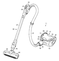
図6において、11は電気掃除機を示す。この電気掃除機11は、掃除機本体13を備えている。また、この電気掃除機11は、集塵部14を備えている。さらに、この電気掃除機11は、吸引源である電動送風機15を備えている。また、この電気掃除機11は、図示しない電源部を備えている。さらに、この電気掃除機11は、図示しない制御部を備えている。また、この電気掃除機11は、設定部としての設定ボタン20を備えている。なお、本実施形態では、電気掃除機11は、被掃除面としての床面上を走行可能な掃除機本体13に対して着脱可能な風路体22を備えるキャニスタ型の電気掃除機とする。
掃除機本体13は、走行輪24を備える。また、この掃除機本体13は、本体部25を備える。そして、この掃除機本体13は、走行輪24により、床面を走行可能となっている。なお、以下、前後方向および両側方向(幅方向)については、掃除機本体13の走行方向を基準とし、例えば風路体22側を前側、その反対側を後側とする。
走行輪24は、例えば本体部25の両側部にそれぞれ回転可能に設けられている。すなわち、これら走行輪24は、水平方向(略水平方向も含む)に沿って回転軸を有している。これら走行輪24は、互いに同軸(略同軸も含む)に位置している。これら走行輪24は、大径に形成されている。
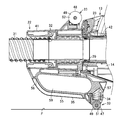
本体部25は、電動送風機15を内蔵している。また、この本体部25は、電源部を内蔵している。さらに、この本体部25は、制御部を内蔵している。本実施形態において、本体部25は、さらに集塵部14を内蔵していてもよい。図1および図2に示すように、この本体部25は、少なくとも一部の外形が走行輪24の外形よりも小さく形成されている。例えば、この本体部25は、少なくとも、走行輪24の回転軸を含む仮想的な鉛直面(上下方向および幅方向に広がる面)Pよりも後側(風路体22に対して反対側)の外形が走行輪24の外形よりも小さく形成されている。本実施形態において、この本体部25は、上部から後部を経由して下部に亘る部分の外形が連続的に走行輪24の外形よりも小さく形成されている。このため、この本体部25は、走行輪24の回転軸を中心として、鉛直面Pに対して一側と他側とに亘る範囲で揺動(回動)可能となっている。換言すれば、本体部25は、前側(風路体22側)が鉛直面Pに対して一側となる位置(図1)と、前側(風路体22)側が鉛直面Pに対して他側となる位置(図2)との間で連続的に揺動(回動)可能となっている。このため、本体部25は、鉛直面Pに対して一側に揺動した位置と、鉛直面Pに対して他側に揺動した位置とで、上下が反転可能となっている。また、この本体部25は、第1本体部である主本体部27を備える。さらに、この本体部25は、第2本体部である延出部28を備えていてもよい。なお、以下、説明をより明確にするために、本体部25が図1に示す状態となっている位置を一方向揺動位置である正位置、本体部25が図2に示す状態となっている位置を他方向揺動位置である逆位置と定義する。
主本体部27は、走行輪24の外形よりも小さい外形を有する部分である。この主本体部27は、本体部25の上部から後部を経由して下部に亘る部分を構成している。この主本体部27は、例えば円筒面の少なくとも一部に沿う外形を有している。本実施形態において、この主本体部27は、例えば半円筒面状の外形を有している。この主本体部27は、走行輪24と同軸状(略同軸状も含む)に配置されている。すなわち、この主本体部27の両側部に走行輪24がそれぞれ軸支されている。
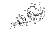
延出部28は、走行輪24の外形よりも大きい外形を有する部分である。この延出部28は、主本体部27と一体に形成されている。この延出部28は、例えば走行輪24の径方向に沿って主本体部27から延出している。例えば、この延出部28の上部および下部は、主本体部27の上部および下部から、それぞれこの主本体部27の接線方向に沿って延出している。また、この延出部28には、図3および図4に示す被接続部29が設けられている。すなわち、掃除機本体13は、被接続部29を備えている。なお、延出部28は、必須の構成ではない。
被接続部29は、風路体22の下流端部である基端部が接続される開口部である。この被接続部29は、本体部25の前端部に開口されている。本実施形態において、この被接続部29は、例えば延出部28の前端部に位置している。また、この被接続部29は、延出部28の幅方向の中央部(略中央部も含む)に位置している。この被接続部29は、集塵部14と連通して形成されている。すなわち、この被接続部29は、集塵部14に形成されていてもよい。
集塵部14は、電動送風機15(図6)の駆動により生じる負圧を利用して空気とともに吸い込んだ塵埃を空気から捕集する部分である。この集塵部14は、掃除機本体13(本体部25)に一体的に組み込まれていてもよいし、掃除機本体13(本体部25)に対して着脱可能でもよい。
図6に示す電動送風機15は、電動機によりファンを回転させることで負圧を生じさせ、塵埃を空気とともに集塵部14へと吸い込むものである。
電源部は、例えば商用交流電源に接続される電源コードを備えるコードリール装置や、二次電池などの電池が用いられる。
制御部は、電動送風機15などの動作を制御するものである。すなわち、この制御部は、電源部から電動送風機15などへの通電量を制御することで、電動送風機15などのオンオフや動作パワーなどの動作状態を制御するものである。この制御部としては、例えばマイコンなどが用いられる。
設定ボタン20は、電動送風機15などの動作を使用者が設定するためのものである。この設定ボタン20は、本実施形態では例えば風路体22に設けられているが、例えば掃除機本体13に設けられていてもよい。
図1ないし図6に示す風路体22は、電動送風機15の駆動により生じる負圧を床面などに作用させるものである。すなわち、この風路体22は、電動送風機15の吸込側に接続されるものである。また、この風路体22は、キャニスタ型の電気掃除機11において、使用者が掃除機本体13を引っ張って走行させることを可能にするものである。この風路体22は、例えば掃除機本体13に対して着脱可能となっている。この風路体22は、ホース体31を備える。また、この風路体22は、接続体(取付具)32を備える。さらに、この風路体22は、支持部材33を備える。また、この風路体22は、付勢部材34(図3)を備えていてもよい。さらに、この風路体22は、本体把持部35を備えていてもよい。また、この風路体22は、手元操作部36を備える。また、この風路体22は、延長管37を備えていてもよい。さらに、この風路体22は、吸込口体38を備えていてもよい。したがって、電気掃除機11は、ホース体31を備える。また、電気掃除機11は、接続体32を備える。さらに、電気掃除機11は、支持部材33を備える。また、電気掃除機11は、付勢部材34を備えていてもよい。さらに、電気掃除機11は、本体把持部35を備えていてもよい。また、電気掃除機11は、手元操作部36を備える。さらに、電気掃除機11は、延長管37を備えていてもよい。また、電気掃除機11は、吸込口体38を備えていてもよい。
ホース体31は、可撓性を有する長尺の筒状に形成されている。
接続体32は、風路体22を掃除機本体13の本体部25(被接続部29)に対して接続するものである。より詳細に、この接続体32は、ホース体31の下流端側である基端側(一端側)を掃除機本体13の本体部25(被接続部29)に対して接続するものである。この接続体32は、掃除機本体13とは別体で設けられている。また、この接続体32は、保持部41を備える。さらに、この接続体32は、接続部42を備える。また、この接続体32は、側部支持部43を備えていてもよい。
保持部41は、ホース体31の基端側を保持するものである。この保持部41は、直管状、すなわち円筒状(略円筒状も含む)に形成されている。この保持部41は、前後方向に沿って位置している。また、この保持部41の先端部である一端部から、ホース体31が突出している。このため、ホース体31の基端部が、本体部25の径方向に沿って位置するようになっている。また、この保持部41の基端部である他端部は、本体部25(延出部28)の前端部に接触している。
接続部42は、被接続部29に挿入されて、風路体22と集塵部14とを連通させるものである。この接続部42は、例えば保持部41と同軸(略同軸も含む)に形成されている。また、この接続部42は、保持部41の基端側に突出している。したがって、接続部42は、保持部41に対してホース体31と反対側に位置している。
側部支持部43は、掃除機本体13の本体部25(被接続部29)に対して接続された接続体32を幅方向に安定させるものである。側部支持部43は、保持部41の両側にそれぞれ突設されている。これら側部支持部43は、本体部25(延出部28)の前端部に沿って幅方向に延びている。また、側部支持部43には、図示しないクランプが設けられている。したがって、電気掃除機11(風路体22)は、クランプを備える。このクランプは、風路体22を掃除機本体13に対して着脱可能に固定するものである。このクランプは、例えば掃除機本体13(本体部25)に設けられていてもよい。
支持部材33は、床Fとの接触によりホース体31の一端側である基端側が床Fに対して非接触となる位置に本体部25の各揺動端(揺動限界位置)を規定するものである。すなわち、支持部材33は、走行輪24の回転軸を中心として揺動させた本体部25を床Fに対して支持することで本体部25のそれ以上の揺動を規制することにより、ホース体31の基端側の床Fとの接触を防止するものである。支持部材33は、接続体32に対して本体部25の揺動一方向側の位置と揺動他方向側の位置とにそれぞれ設けられている。換言すれば、支持部材33は、接続体32(風路体22)の基端側(接続体32(保持部41)に保持されている位置)の中心軸を挟んで揺動方向の互いに反対側である上側と下側とに位置する。すなわち、支持部材33としては、接続体32に対して本体部25の揺動一方向側に位置する第1支持部材である正位置支持部材47と、接続体32に対して本体部25の揺動他方向側に位置する第2支持部材である逆位置支持部材48とが設定されている。また、支持部材33は、車輪49を備えていてもよい。
正位置支持部材47は、鉛直面Pに対して本体部25が一方向に揺動した状態で床Fに対して接触することで、本体部25の一方向の揺動端を規定するものである。すなわち、この正位置支持部材47は、本体部25を正位置で床Fに対して支持するものである。したがって、この正位置支持部材47は、本体部25が正位置の状態で接続体32に対して下部に位置し、本体部25が逆位置の状態で接続体32に対して上部に位置する。また、この正位置支持部材47は、保持部41よりも後方に位置している。さらに、この正位置支持部材47は、例えば本体把持部35に設けられていてもよい。このため、この正位置支持部材47は、本体部25の正位置において、本体部25の下部に位置する。さらに、この正位置支持部材47は、例えば接続体32(本体把持部35)に対して上下方向に回動可能に軸支されていてもよい。そして、この正位置支持部材47は、床Fに接触した状態で、ホース体31の基端側と床Fとの間に上下に間隙を形成するようになっている。本実施形態において、この正位置支持部材47は、床Fに接触した状態で、接続体32を例えば水平方向(略水平方向も含む)に沿って位置させるようになっている。
逆位置支持部材48は、鉛直面Pに対して本体部25が他方向に揺動した状態で床Fに対して接触することで、本体部25の他方向の揺動端を規定するものである。すなわち、この逆位置支持部材48は、本体部25を逆位置に床Fに対して支持するものである。したがって、この逆位置支持部材48は、本体部25が逆位置の状態で接続体32に対して下部に位置し、本体部25が正位置の状態で接続体32に対して上部に位置する。また、この逆位置支持部材48は、本体部25の逆位置において、保持部41の下部に位置する。このため、この逆位置支持部材48は、本体部25の正位置において、本体部25の前方の下部に位置する。そして、この逆位置支持部材48は、床Fに接触した状態で、ホース体31の基端側と床Fとの間に上下に間隙を形成するようになっている。本実施形態において、この逆位置支持部材48は、床Fに接触した状態で、接続体32を水平方向(略水平方向も含む)に沿って位置させるようになっている。
この結果、本実施形態において、本体部25は、走行輪24の回転軸を中心として正位置と逆位置との間で前後方向に例えば約180°揺動可能となっている。
車輪49は、掃除機本体13の走行を補助する補助輪である。また、車輪49は、走行輪24よりも小径に設けられた従動輪である。車輪49は、本実施形態において、正位置支持部材47と逆位置支持部材48とのそれぞれに回転可能に設けられている。すなわち、本実施形態において、車輪49には、正位置支持部材47に回転可能に備えられる第1車輪である正位置用車輪51と、逆位置支持部材48に回転可能に備えられる第2車輪である逆位置用車輪52とが設定されている。そして、車輪49が、支持部材33において床Fと直接接触する接地部となっている。なお、車輪49には、床Fとの接触の衝撃を緩和する不織布などの緩衝部材が表面に設けられていてもよいし、車輪49自体が弾性体(例えばゴム、あるいはエラストマなど)により形成されて床Fとの接触の衝撃を緩和する緩衝部材となっていてもよい。また、この車輪49は、必須の構成ではない。
図3に示す付勢部材34は、支持部材33を接続体32に対して付勢するものである。すなわち、この付勢部材34は、支持部材33を床Fの凹凸や小さい障害物などによる段差に追従させて支持部材33と床Fとを適切な接触圧で接触させた状態を維持するものである。また、この付勢部材34は、支持部材33の床Fとの接触の衝撃を緩和するものである。本実施形態において、付勢部材34は、例えば正位置支持部材47を接続体32に対して付勢している。すなわち、この付勢部材34は、正位置支持部材47を接続体32に対して突出する方向に付勢している。例えば、この付勢部材34としては、コイルばねが用いられるが、トーションばねや弾性体などでもよい。なお、この付勢部材34は、逆位置支持部材48を接続体32に対して付勢するものでもよいし、正位置支持部材47を接続体32に対して付勢するものと、逆位置支持部材48を接続体32に対して付勢するものとのそれぞれが設定されていてもよい。また、この付勢部材34は、必須の構成ではない。
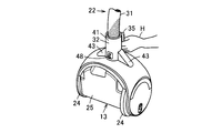
図1ないし図3に示す本体把持部35は、掃除機本体13を持ち上げる際に使用者によって把持されるものである。特に、この本体把持部35は、電気掃除機11の収納作業時に使用者の手Hで把持されるものである(図5)。この本体把持部35は、接続体32にて、掃除機本体13の走行輪24による走行方向、すなわち前後方向に沿って設けられている。本実施形態において、この本体把持部35は、接続体32に対して環状に設けられた環状部である。すなわち、この本体把持部35は、使用者により把持される被把持部55と、この被把持部55の端部を接続体32と連結する一端側連結部(第1連結部)である前部連結部56および他端側連結部(第2連結部)である後部連結部57とを備える。被把持部55は、使用者が把持可能な太さであり、把持可能な長さを有するように形成されている。この被把持部55の長さ方向が、掃除機本体13の走行輪24による走行方向、すなわち前後方向に沿うようにして、本体把持部35が形成されている。また、本実施形態において、この本体把持部35は、保持部41に一体に設けられている。したがって、この本体把持部35と接続体32(保持部41)との間に、幅方向に貫通する開口59が形成されている。また、この本体把持部35は、風路体22(ホース体31)側の端部である前端部が、この風路体22(ホース体31)の中心に向かう方向に傾斜している。すなわち、前部連結部56は、前方に向かって風路体22(ホース体31)の中心に接近する方向に傾斜した傾斜部である。さらに、この本体把持部35は、被把持部55が前方に向かって風路体22(ホース体31)の中心に接近する方向に傾斜している。したがって、本体把持部35全体として、前方に向かって風路体22(ホース体31)の中心に接近する方向に傾斜している。また、この本体把持部35は、本実施形態において、本体部25が正位置の状態で接続体32の下部、本体部25が逆位置の状態で接続体32の上部となる位置に設けられている。そして、本実施形態において、この本体把持部35には、被把持部55の後端部寄り、すなわち被把持部55と後部連結部57とが連続する位置近傍に、正位置支持部材47が設けられている。なお、この本体把持部35は、必須の構成ではない。
図6に示す手元操作部36は、握り管などとも呼ばれ、ホース体31の上流端側である先端側(他端側)に設けられている。この手元操作部36は、ホース体31の先端側と延長管37の下流端側である基端側(一端側)とを接続するものである。この手元操作部36には、例えば設定ボタン20が配置されていてもよい。また、この手元操作部36は、使用者が掃除の際に把持する部分である。この手元操作部36には、例えば風路体22の把持操作用の把持部61が突設されていてもよい。この把持部61には、設定ボタン20が配置されていてもよい。なお、把持部61は、必須の構成ではなく、使用者が手元操作部36を直接把持するようにすることもできる。この場合、設定ボタン20は、手元操作部36に直接配置されていてもよい。
延長管37は、例えば硬質の合成樹脂により直管状に形成されている。この延長管28は、例えば基端側がホース体31の先端側(手元操作部36)と接続されるとともに、先端側が吸込口体38と接続される。なお、この延長管37は、必須の構成ではない。
吸込口体38は、電動送風機15の駆動により生じた負圧によって床面から塵埃を吸い込むものである。この吸込口体38は、本実施形態において、例えば床面に載置されてこの床面上を移動される床ブラシとする。この吸込口体38は、ケース体63を備えている。また、この吸込口体38は、延長管37の先端側に接続される接続管64を備えている。この吸込口体38は、回転清掃体を備えていてもよい。なお、この吸込口体38は、必須の構成ではない。
次に、上記一実施形態による掃除動作を説明する。
概略として、使用者は、掃除機本体13に対して接続体32により接続されたホース体31の先端部に延長管37および吸込口体38を接続した状態で、吸込口体38を床面上に載置し、把持部61を把持して設定ボタン20を操作することで電動送風機15を駆動させる。そして、風路体22により掃除機本体13を引っ張って適宜の位置に移動させては吸込口体38を床面上で前後に繰り返し走行させて、電動送風機15の駆動により生じた負圧を利用して吸込口体38の吸込口から床面の塵埃を空気とともに吸い込む。
このとき、掃除機本体13は、本体部25が正位置でも逆位置でも、いずれであっても使用できる。例えば本体部25が正位置の場合には、正位置支持部材47が正位置用車輪51で床Fと接触し(図1)、両側の走行輪24とともに掃除機本体13(本体部25)を床Fに対して3点支持することで、安定的な走行が可能になる。このとき、正位置支持部材47によって、ホース体31の基端側は、床Fに対して高さが確保されて床Fとは非接触となり、床Fに擦り付けられることがない。一方、例えば本体部25が逆位置の場合には、逆位置支持部材48が逆位置用車輪52で床Fと接触し(図2)、両側の走行輪24とともに掃除機本体13(本体部25)を床Fに対して3点支持することで、安定的な走行が可能になる。このとき、逆位置支持部材48によって、ホース体31の基端側は、床Fに対して高さが確保されて床Fとは非接触となり、床Fに擦り付けられることがない。
また、例えば方向転換の際などには、走行輪24の回転軸を中心として本体部25の上下を反転させるように揺動させることで、正位置と逆位置とが転換し、その場で走行方向の反転が可能となる。
なお、吸込口体38の吸込口から吸い込んだ含塵空気は、接続管64から、延長管37、ホース体31を経由し、集塵部14へと吸い込まれる。この集塵部14において、含塵空気中の塵埃が分離捕集され、塵埃が分離された空気が電動送風機15へと吸い込まれ、この電動送風機15を冷却した後、掃除機本体13から排気される。掃除が終了すると、使用者が設定ボタン20を操作することで電動送風機15を停止させる。集塵部14に捕集された塵埃は、必要に応じて廃棄される。
このように、本実施形態によれば、接続体32に対して本体部25の揺動一方向側の位置と揺動他方向側の位置とに、床Fとの接触によりホース体31の一端側が床Fに対して非接触となる位置に本体部25の各揺動端を規定する支持部材33を設けることで、本体部25の揺動時にホース体31の床Fからの高さが確保されてホース体31の下部が床Fと接触しにくくなり、また、ホース体31の下部の床Fとの接触によってホース体31の基端が上方に押されて接続体32(保持部41)に対してホース体31の基端が当たって変形したりホース体31の基端側の下部が掃除機本体13の走行時に床Fに擦り付けられたりしにくく、ホース体31を傷付けにくい。
また、支持部材33(正位置支持部材47)を接続体32に対して付勢部材34により付勢することで、支持部材33(正位置支持部材47)が床Fに接触する際の衝撃を付勢部材34により緩和できるので、使用者が気兼ねなく掃除機本体13の本体部25を揺動させて反転させることができる。
さらに、支持部材33が、床Fに接地する車輪49を備えることで、走行輪24とともにこの車輪49によって掃除機本体13を走行可能に支持し、走行の安定性を向上できる。しかも、正位置支持部材47を接続体32(本体把持部35)に対して回動可能に軸支するとともに付勢部材34により接続体32(本体把持部35)に対して突出する方向に付勢することで、正位置用車輪51が床Fとの適切な接触圧力を維持し、掃除機本体13を円滑に走行させることが可能になる。
そして、把持される本体把持部35を接続体32に設けることで、使用者がこの本体把持部35を把持して掃除機本体13を持ち上げることができる。
また、本体把持部35を、掃除機本体13の走行輪24による走行方向に沿って設けることで、例えば掃除機本体13の前部(風路体22側)を上方に向けて立てた状態で掃除機本体13を本体把持部35によって持ち上げやすくなるとともに、支持部材33によって接続体32と床Fとの間に形成されるスペースを有効に利用し、本体把持部35を省スペースで配置できる。
しかも、本体把持部35のホース体31側の端部(前部連結部56)をこのホース体31の中心に向かう方向に傾斜させることで、例えば本体把持部35を下側とする位置、本実施形態では正位置において、床Fに対向する本体把持部35のホース体31側の端部(前部連結部56)が床F上の凹凸や小さい障害物O(図1)などに対していわば橇として作用し、これらを容易に乗り越えて掃除機本体13を円滑に走行させることが可能になる。さらに、本体把持部35全体として、前部に向かってホース体31の中心に接近する方向に傾斜させているので、床F上の凹凸や小さい障害物などをより容易に乗り越え可能となる。
なお、上記一実施形態において、支持部材33の正位置支持部材47に代えて、逆位置支持部材48を接続体32に対して回動可能に設けてもよいし、正位置支持部材47および逆位置支持部材48をそれぞれ接続体32に対して回動可能に設けてもよい。この場合には、逆位置支持部材48も付勢部材34により付勢することが好ましい。
また、本体把持部35は、本体部25が逆位置の状態で接続体32の下部、本体部25が正位置の状態で接続体32の上部となる位置に設けてもよいし、本体部25が正位置の状態で接続体32の下部に位置する本体把持部35と、本体部25が逆位置の状態で接続体32の下部に位置する本体把持部35とを、それぞれ設けてもよい。すなわち、本体把持部35は、本体部25の揺動一方向側(正位置側)と揺動他方向側(逆位置側)とのそれぞれの位置で接続体32に設けられていてもよい。
さらに、支持部材33自体を弾性体により形成する構成としてもよい。この場合には、付勢部材34を用いなくても、支持部材33が床Fに接触する際の衝撃を緩和できるので、使用者が気兼ねなく掃除機本体13の本体部25を揺動させて反転させることができる。
本発明のいくつかの実施形態を説明したが、これらの実施形態は、例として提示したものであり、発明の範囲を限定することは意図していない。これら新規な実施形態は、その他の様々な形態で実施されることが可能であり、発明の要旨を逸脱しない範囲で、種々の省略、置き換え、変更を行うことができる。これら実施形態やその変形は、発明の範囲や要旨に含まれるとともに、特許請求の範囲に記載された発明とその均等の範囲に含まれる。
Claims (8)
- 走行輪と、この走行輪の回転軸を含む鉛直面に対して一側と他側とに亘る範囲で揺動可能に設けられた本体部とを備えた掃除機本体と、
ホース体と、
このホース体の一端側を前記本体部に対して接続する接続体と、
この接続体に対して前記本体部の揺動一方向側の位置と揺動他方向側の位置とにそれぞれ設けられ、床との接触により前記ホース体の一端側が床に対して非接触となる位置に前記本体部の各揺動端を規定する支持部材と
を具備したことを特徴とした電気掃除機。 - 支持部材を接続体に対して付勢する付勢部材を具備した
ことを特徴とした請求項1記載の電気掃除機。 - 支持部材は、弾性体により形成されている
ことを特徴とした請求項1または2記載の電気掃除機。 - 支持部材は、床に接地する車輪を備えた
ことを特徴とした請求項1ないし3いずれか一記載の電気掃除機。 - 接続体に設けられ、把持される本体把持部を備えた
ことを特徴とした請求項1ないし4いずれか一記載の電気掃除機。 - 本体把持部は、掃除機本体の走行輪による走行方向に沿って設けられている
ことを特徴とした請求項5記載の電気掃除機。 - 本体把持部は、ホース体側の端部がこのホース体の中心に向かう方向に傾斜している
ことを特徴とした請求項6記載の電気掃除機。 - 本体把持部は、本体部の揺動一方向側と揺動他方向側とのそれぞれの位置で接続体に設けられている
ことを特徴とした請求項5ないし7いずれか一記載の電気掃除機。
Priority Applications (2)
| Application Number | Priority Date | Filing Date | Title |
|---|---|---|---|
| CN201880014445.1A CN110352027B (zh) | 2017-06-14 | 2018-06-12 | 电动吸尘器 |
| KR1020197020876A KR102286412B1 (ko) | 2017-06-14 | 2018-06-12 | 전기 청소기 |
Applications Claiming Priority (2)
| Application Number | Priority Date | Filing Date | Title |
|---|---|---|---|
| JP2017-116767 | 2017-06-14 | ||
| JP2017116767A JP7174507B2 (ja) | 2017-06-14 | 2017-06-14 | 電気掃除機 |
Publications (1)
| Publication Number | Publication Date |
|---|---|
| WO2018230554A1 true WO2018230554A1 (ja) | 2018-12-20 |
Family
ID=64659588
Family Applications (1)
| Application Number | Title | Priority Date | Filing Date |
|---|---|---|---|
| PCT/JP2018/022383 Ceased WO2018230554A1 (ja) | 2017-06-14 | 2018-06-12 | 電気掃除機 |
Country Status (4)
| Country | Link |
|---|---|
| JP (1) | JP7174507B2 (ja) |
| KR (1) | KR102286412B1 (ja) |
| CN (1) | CN110352027B (ja) |
| WO (1) | WO2018230554A1 (ja) |
Citations (9)
| Publication number | Priority date | Publication date | Assignee | Title |
|---|---|---|---|---|
| JPS4872969A (ja) * | 1971-12-29 | 1973-10-02 | ||
| JPH01168241U (ja) * | 1988-05-16 | 1989-11-27 | ||
| JPH04103851U (ja) * | 1991-01-21 | 1992-09-08 | 株式会社富士通ゼネラル | 電気掃除機 |
| JPH05168577A (ja) * | 1991-12-24 | 1993-07-02 | Hitachi Ltd | 電気掃除機 |
| JPH05344940A (ja) * | 1992-06-15 | 1993-12-27 | Matsushita Electric Ind Co Ltd | 電気掃除機 |
| JPH0630859A (ja) * | 1992-07-16 | 1994-02-08 | Sanyo Electric Co Ltd | 電気掃除機 |
| JP2001029280A (ja) * | 1999-07-26 | 2001-02-06 | Hitachi Ltd | 電気掃除機 |
| JP2002102129A (ja) * | 2000-10-02 | 2002-04-09 | Matsushita Electric Ind Co Ltd | 電気掃除機及び充電台 |
| JP2006149728A (ja) * | 2004-11-30 | 2006-06-15 | Toshiba Tec Corp | 電気掃除機 |
Family Cites Families (9)
| Publication number | Priority date | Publication date | Assignee | Title |
|---|---|---|---|---|
| JPS467758Y1 (ja) * | 1966-08-08 | 1971-03-18 | ||
| JP4205466B2 (ja) | 2003-03-20 | 2009-01-07 | 日立アプライアンス株式会社 | 電気掃除機 |
| KR100592099B1 (ko) * | 2004-06-09 | 2006-06-21 | 삼성광주전자 주식회사 | 연장관 지지장치 및 이를 구비한 진공청소기 |
| CN1977748A (zh) * | 2005-12-05 | 2007-06-13 | 乐金电子(天津)电器有限公司 | 防止吸尘器脚轮震动的结构 |
| JP5390204B2 (ja) * | 2009-01-23 | 2014-01-15 | 株式会社東芝 | 電気掃除機 |
| GB2519968A (en) * | 2013-11-01 | 2015-05-13 | Techtronic Floor Care Tech Ltd | Surface cleaning Apparatus |
| KR101617957B1 (ko) * | 2014-08-26 | 2016-05-03 | 엘지전자 주식회사 | 진공 청소기 |
| GB2533145A (en) | 2014-12-11 | 2016-06-15 | Techtronic Ind Co Ltd | Surface cleaning apparatus |
| WO2016184483A1 (en) * | 2015-05-15 | 2016-11-24 | Arcelik Anonim Sirketi | A cordless vacuum cleaner |
-
2017
- 2017-06-14 JP JP2017116767A patent/JP7174507B2/ja active Active
-
2018
- 2018-06-12 WO PCT/JP2018/022383 patent/WO2018230554A1/ja not_active Ceased
- 2018-06-12 CN CN201880014445.1A patent/CN110352027B/zh not_active Expired - Fee Related
- 2018-06-12 KR KR1020197020876A patent/KR102286412B1/ko not_active Expired - Fee Related
Patent Citations (9)
| Publication number | Priority date | Publication date | Assignee | Title |
|---|---|---|---|---|
| JPS4872969A (ja) * | 1971-12-29 | 1973-10-02 | ||
| JPH01168241U (ja) * | 1988-05-16 | 1989-11-27 | ||
| JPH04103851U (ja) * | 1991-01-21 | 1992-09-08 | 株式会社富士通ゼネラル | 電気掃除機 |
| JPH05168577A (ja) * | 1991-12-24 | 1993-07-02 | Hitachi Ltd | 電気掃除機 |
| JPH05344940A (ja) * | 1992-06-15 | 1993-12-27 | Matsushita Electric Ind Co Ltd | 電気掃除機 |
| JPH0630859A (ja) * | 1992-07-16 | 1994-02-08 | Sanyo Electric Co Ltd | 電気掃除機 |
| JP2001029280A (ja) * | 1999-07-26 | 2001-02-06 | Hitachi Ltd | 電気掃除機 |
| JP2002102129A (ja) * | 2000-10-02 | 2002-04-09 | Matsushita Electric Ind Co Ltd | 電気掃除機及び充電台 |
| JP2006149728A (ja) * | 2004-11-30 | 2006-06-15 | Toshiba Tec Corp | 電気掃除機 |
Also Published As
| Publication number | Publication date |
|---|---|
| CN110352027A (zh) | 2019-10-18 |
| JP2019000296A (ja) | 2019-01-10 |
| JP7174507B2 (ja) | 2022-11-17 |
| KR20190097200A (ko) | 2019-08-20 |
| KR102286412B1 (ko) | 2021-08-05 |
| CN110352027B (zh) | 2021-12-07 |
Similar Documents
| Publication | Publication Date | Title |
|---|---|---|
| JP6714091B2 (ja) | 真空掃除機 | |
| US6374453B1 (en) | Convertible vacuum cleaner | |
| CN101822507B (zh) | 地面工具 | |
| KR101496008B1 (ko) | 전기 청소기의 흡입구체 및 이 흡입구체를 구비한 전기 청소기 | |
| KR20060134418A (ko) | 업라이트형 진공청소기 | |
| JP6121656B2 (ja) | 電気掃除機およびその吸込口体 | |
| JP2019000296A (ja) | 電気掃除機 | |
| JP2014018256A (ja) | 電気掃除機の吸込具及び電気掃除機 | |
| JP5620089B2 (ja) | 電気掃除機 | |
| JP2006136503A (ja) | 電気掃除機の吸込口体および電気掃除機 | |
| JP5380160B2 (ja) | 吸込口体および電気掃除機 | |
| JP2006346279A (ja) | 電気掃除機およびその吸込口体 | |
| JP2011055906A (ja) | 電気掃除機用吸込口体及び電気掃除機 | |
| JP4234743B2 (ja) | 吸込口体および電気掃除機 | |
| JP2000237102A (ja) | 電気掃除機の吸口 | |
| JP4358211B2 (ja) | 吸込口体および電気掃除機 | |
| JP5259210B2 (ja) | 電気掃除機 | |
| JP2014168606A (ja) | 電気掃除機 | |
| JP4286852B2 (ja) | 吸込口体および電気掃除機 | |
| JP2012200556A (ja) | 電気掃除機 | |
| JP2014054574A (ja) | 電気掃除機用吸込口体及び電気掃除機 | |
| JP2016047143A (ja) | 電気掃除機およびその吸込口体 | |
| JP5608298B2 (ja) | 電気掃除機用吸込口体、及び電気掃除機 | |
| JP2010252981A (ja) | 吸込口体および電気掃除機 | |
| KR20120032440A (ko) | 전기 청소기 |
Legal Events
| Date | Code | Title | Description |
|---|---|---|---|
| 121 | Ep: the epo has been informed by wipo that ep was designated in this application |
Ref document number: 18817675 Country of ref document: EP Kind code of ref document: A1 |
|
| ENP | Entry into the national phase |
Ref document number: 20197020876 Country of ref document: KR Kind code of ref document: A |
|
| NENP | Non-entry into the national phase |
Ref country code: DE |
|
| 122 | Ep: pct application non-entry in european phase |
Ref document number: 18817675 Country of ref document: EP Kind code of ref document: A1 |