WO2018230503A1 - 管継手 - Google Patents
管継手 Download PDFInfo
- Publication number
- WO2018230503A1 WO2018230503A1 PCT/JP2018/022227 JP2018022227W WO2018230503A1 WO 2018230503 A1 WO2018230503 A1 WO 2018230503A1 JP 2018022227 W JP2018022227 W JP 2018022227W WO 2018230503 A1 WO2018230503 A1 WO 2018230503A1
- Authority
- WO
- WIPO (PCT)
- Prior art keywords
- nipple
- display member
- radial direction
- tightening
- axial direction
- Prior art date
- Legal status (The legal status is an assumption and is not a legal conclusion. Google has not performed a legal analysis and makes no representation as to the accuracy of the status listed.)
- Ceased
Links
Images


Classifications
-
- F—MECHANICAL ENGINEERING; LIGHTING; HEATING; WEAPONS; BLASTING
- F16—ENGINEERING ELEMENTS AND UNITS; GENERAL MEASURES FOR PRODUCING AND MAINTAINING EFFECTIVE FUNCTIONING OF MACHINES OR INSTALLATIONS; THERMAL INSULATION IN GENERAL
- F16L—PIPES; JOINTS OR FITTINGS FOR PIPES; SUPPORTS FOR PIPES, CABLES OR PROTECTIVE TUBING; MEANS FOR THERMAL INSULATION IN GENERAL
- F16L33/00—Arrangements for connecting hoses to rigid members; Rigid hose-connectors, i.e. single members engaging both hoses
- F16L33/22—Arrangements for connecting hoses to rigid members; Rigid hose-connectors, i.e. single members engaging both hoses with means not mentioned in the preceding groups for gripping the hose between inner and outer parts
- F16L33/223—Arrangements for connecting hoses to rigid members; Rigid hose-connectors, i.e. single members engaging both hoses with means not mentioned in the preceding groups for gripping the hose between inner and outer parts the sealing surfaces being pressed together by means of a member, e.g. a swivel nut, screwed on or into one of the joint parts
-
- F—MECHANICAL ENGINEERING; LIGHTING; HEATING; WEAPONS; BLASTING
- F16—ENGINEERING ELEMENTS AND UNITS; GENERAL MEASURES FOR PRODUCING AND MAINTAINING EFFECTIVE FUNCTIONING OF MACHINES OR INSTALLATIONS; THERMAL INSULATION IN GENERAL
- F16L—PIPES; JOINTS OR FITTINGS FOR PIPES; SUPPORTS FOR PIPES, CABLES OR PROTECTIVE TUBING; MEANS FOR THERMAL INSULATION IN GENERAL
- F16L2201/00—Special arrangements for pipe couplings
- F16L2201/10—Indicators for correct coupling
Definitions
- the present invention relates to a pipe joint used for pipe connection of a pipe made of a hard material or a pipe such as a hose or a tube made of a soft material.
- connection device for a conduit or a hose provided with two separate display rings (see, for example, Patent Document 1).
- Two separate display rings are respectively attached to the connection body and the union nut, and are provided with a stopper surface.
- a window is created to maintain the spacing between both stopper surfaces extending in the circumferential direction, and this window or stopper surface can be interpreted as a mark that reveals the assembled condition.
- a pipe joint according to the present invention includes a nipple having an insertion part that is inserted into a pipe body and radially faces the inner surface of the pipe body, and the insertion part of the nipple is inserted.
- a fastening member provided to be movable in the axial direction with respect to the outer surface of the tubular body, and a display member provided to be sandwiched between the nipple and the fastening member in the axial direction.
- the display member 3 is arranged between the nipple 1 and the fastening member 2 with respect to either the nipple 1 or the fastening member 2.
- the fastening member 2 covered on the outside thereof is moved in the axial direction with respect to the nipple 1.
- the tubular body B is sandwiched in the radial direction between the nipple 1 and the fastening member 2 and is connected so as not to be pulled out.
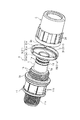
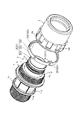
- the pipe joint A includes a nipple 1 having an insertion portion 1a that is inserted into the tube body B and faces the inner surface B1 of the tube body B in the radial direction, and an insertion portion of the nipple 1
- the fastening member 2 provided to be movable in the axial direction with respect to the outer surface B2 of the tube body B into which 1a is inserted, and the display member 3 provided (attached) between the nipple 1 and the fastening member 2 are mainly used. As a major component.
- tube removal direction U As the axial direction in which the fastening member 2 moves, the direction in which the tube B is inserted into the nipple 1 and the direction in which the fastening member 2 moves toward the nipple 1 is hereinafter referred to as a “tube insertion direction N”.
- tube removal direction U The direction in which the tube B is removed in the direction opposite to N and the direction in which the fastening member 2 moves away from the nipple 1 is hereinafter referred to as “tube removal direction U”.
- the tubular body B is formed of, for example, a pipe made of a hard material such as a hard resin or a metal, or a flexible soft material such as a soft synthetic resin such as vinyl chloride, silicone rubber, or other rubber, such as a hose or a tube. Etc. Furthermore, the tubular body B is cut into a predetermined length by a cutter (not shown) such as a pipe cutter or scissors. As the tube B, it is preferable to use a tube having a flat inner surface B1 and an outer surface B2 and having a cut surface B3 cut at a substantially vertical or nearly vertical angle. A connection end Ba having a predetermined length is inserted into the insertion portion 1a of the nipple 1 from the cut surface B3 of the tube B.
- a pipe having a single layer structure is used, and is fitted along the insertion portion 1a of the nipple 1 in a state where the diameter of the connection end portion Ba is larger than that of other portions.
- a pipe having a multi-layer structure in which a metal layer such as aluminum and a hard resin layer are integrally laminated a pipe having a multi-layer structure in which a metal layer such as aluminum and a hard resin layer are integrally laminated, a hose or a tube having a single-layer structure or a multi-layer structure, etc. It is possible to make changes such as using or fitting the insertion end 1a of the nipple 1 without deforming the connecting end portion Ba of the tube body B from the other part.
- the nipple 1 is formed of a rigid material such as a hard synthetic resin or a metal such as brass, and the insertion portion 1a has an outer diameter that is substantially the same as or slightly smaller than the inner diameter of the connection end portion Ba of the tube body B. It is formed in a substantially cylindrical shape. Further, the nipple 1 is formed by pressing a plate material made of a deformable rigid material such as stainless steel, for example, or by other forming processes, so that the nipple 1 has an outer diameter substantially equal to or slightly smaller than the inner diameter of the tube body B. It is also possible to use what is formed in a cylindrical shape.
- the nipple 1 includes a cylindrical insertion portion 1a that is inserted into the connection end portion Ba of the tube B, a guide portion 1b that is provided in a radial direction facing an inner surface of a tightening member 2 described later, and a tightening member 2 described later. And a protrusion 1c provided to face the tip surface in the axial direction.
- the guide portion 1b is a portion that guides a tightening member 2 described later with respect to the nipple 1 so as to freely reciprocate in the axial direction.
- it is a male screw that is screwed into the inner surface of the fastening member 2 described later, and this male screw is inserted into the insertion portion 1a of the nipple 1 and the projection portion. It is formed between 1c.
- the protrusion 1c is formed so as to protrude in the axial direction from the distal end surface of the fastening member 2 described later and the display member 3 described later.
- a hook shape that is annularly continuous in the circumferential direction intersecting the axial direction (the tube insertion direction N or the tube withdrawal direction U). Is formed to protrude.
- a linear groove extending in the axial direction, a slider mechanism, or the like is provided as the guide portion 1b instead of the male screw, or the shape of the protruding portion 1c is changed to an annular shape and is discontinuous in the circumferential direction. It is also possible to make changes such as forming them.
- the insertion portion 1a of the nipple 1 is formed with an annular recess 1d extending in the circumferential direction opposite to the insertion space of the tube B and extending in the circumferential direction, and an elastically deformable ring such as an O-ring is formed in the annular recess 1d.
- the sealing member 1e is fitted and mounted so as to be immovable in the axial direction.
- the seal member 1e has its outer peripheral end slightly protruded from the insertion portion 1a of the nipple 1 and is brought into pressure contact with the inner surface B1 of the connection end portion Ba of the inserted tube B.
- annular recess 1d and a seal member 1e are arranged in the axial direction at a predetermined interval.
- one or three or more annular recesses 1d and seal members 1e are arranged, or formed into a bamboo slab shape in which a plurality of annular protrusions and annular grooves are alternately formed in the axial direction. It is possible to change such as to do.
- the nipple 1 is provided with a joint body 11 to which other equipment (not shown), other pipes (not shown), and the like are connected, and other equipment and other pipes connected to the joint body 11 are provided. It is preferable to connect with the tubular body B.
- a tubular joint body 11 is integrally formed on the back side in the tube insertion direction N with respect to the protrusion 1 c of the nipple 1.
- the joint body 11 includes a connection part 11a for connection to a pipe connection port (not shown) such as another device or another pipe body, and a tool engagement part 11b where a tool (not shown) engages in the circumferential direction. Are integrally formed.
- connection portion 11a When the internal thread is engraved on the inner peripheral surface of the pipe connection port in other equipment connected to the pipe joint A or other pipe bodies, the connection portion 11a is engraved with the corresponding external screw. When an external screw is engraved on the outer peripheral surface of the pipe connection port, an internal screw corresponding to this is engraved. In the illustrated example, an external screw is engraved as the connection portion 11a.
- the shape of the tool engaging portion 11b concave portions and convex portions are alternately and continuously formed in the circumferential direction.
- the nipple 1 and the joint body 11 are separately formed and attached detachably, or the shape of the tool engaging portion 11b is changed to a hexagonal nut shape to which a spanner or a wrench fits. It is also possible to change.
- the fastening member 2 is made of a rigid material such as hard synthetic resin or a metal material that is not easily rusted, such as stainless steel. A part of the fastening member 2 in the axial direction is larger than the connection end Ba of the tubular body B inserted into the insertion portion 1a of the nipple 1. It is formed in a substantially cylindrical shape having an inner diameter.
- the fastening member 2 has a moving means 2a provided on its inner surface so as to face the guide portion 1b of the nipple 1 in the radial direction, and a connecting end portion Ba of the tubular body B into which the nipple 1 and the insertion portion 1a are inserted in the radial direction.
- the tightening member 2 has a tool engaging portion 2d on the exposed portion (outer surface) of which a tool (not shown) is engaged in the circumferential direction.
- the moving means 2a is a part that moves reciprocally in the axial direction in conjunction with the guide portion 1b of the nipple 1. Furthermore, it is preferable that the moving means 2a is linked to the guide portion 1b of the nipple 1 so as to be rotatable in the circumferential direction and is reciprocated by the rotating operation of the fastening member 2. More specifically, the moving means 2a is configured to approach the tip 2c toward the protrusion 1c of the nipple 1 by relative movement in the tube insertion direction N along the guide 1b of the nipple 1. . The tip 2c is configured to be separated from the protrusion 1c of the nipple 1 by a relative movement in the tube pulling direction U opposite to this.
- the moving means 2a is a female screw that is screwed into the spiral groove of the guide portion 1b, and this screw is partially formed on one end side of the inner surface of the fastening member 2.
- the pressing portion 2b presses the outer surface B2 of the connection end Ba of the tube body B toward the insertion portion 1a in the radial direction as the moving means 2a approaches the guide portion 1b of the nipple 1 in the tube insertion direction N.
- the inner surface B1 of the connection end portion Ba of the tube body B is a portion in close contact with the insertion portion 1a of the nipple 1.
- the pressing surface 2b is a tapered surface that is inclined so as to gradually become a small diameter in the tube pull-out direction U, and this tapered surface is the inner surface of the fastening member 2.
- a part is formed on the other end side so as to be in direct contact with the outer surface B2 of the connection end Ba of the tube B.
- a substantially rectangular concave portion and a convex portion are alternately arranged in the circumferential direction along one end side of the outer surface of the fastening member 2. Is formed.
- the moving means 2a is provided with linear protrusions or slider mechanisms that extend in the axial direction instead of the female screws, and the shape and arrangement of the pressing portion 2b are not shown in the drawings. It is also possible to change to. Further, an elastically deformable sleeve is interposed inside the pressing portion 2b so that the pressing portion 2b is indirect contact with the outer surface B2 of the connection end portion Ba of the tube B, or a tool engaging portion. It is also possible to change the shape and arrangement of 2d other than the illustrated example.
- the display member 3 is a tightening confirmation means for displaying the tightening state of the tightening member 2 with respect to the nipple 1 to an operator or the like so that it can be easily confirmed visually or by palpation.
- the display member 3 is disposed so as to be sandwiched in the axial direction with respect to a space formed between the projection 1c of the nipple 1 and the tip 2c of the fastening member 2.
- the display member 3 is made of an elastically deformable material such as a soft synthetic resin. As shown in FIGS. 1 to 6, the display member 3 is formed in an annular shape (ring shape) along the entire outer peripheral surface of the fastening member 2. It is preferable.
- the display member 3 has a deforming portion 3D that is elastically deformed in the axial direction or the radial direction with the (relative) approaching movement of the moving means 2a of the fastening member 2 with respect to the guide portion 1b of the nipple 1.
- the deformation portion 3D is configured such that the amount of deformation in the axial direction or the radial direction gradually increases by moving the distal end portion 2c of the fastening member 2 toward the protrusion portion 1c of the nipple 1.
- the display member 3 is detachably attached to either the protrusion 1c of the nipple 1 or the tip 2c of the fastening member 2 and is temporarily attached to the display member 3 so that it cannot be dropped (held).
- it has 3H.
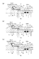
- the first display member 31 is used in which the deformation portion 3D, which is a part of the display member 3, is elastically deformed in the axial direction by movement, and the entire shape of the display member 3 is compressed and deformed in the axial direction.
- the first display member 31 is formed to be elastically deformable across an outer part 31a formed with a large diameter, an inner part 31b formed with a smaller diameter than the outer part 31a, and the outer part 31a and the inner part 31b. And a connecting portion 31c.
- the strength of the connecting portion 31c is determined by the inner portion 31b striking the protruding portion 1c as shown in FIG. 3 (b) as the distal end portion 2c of the tightening member 2 approaches the protruding portion 1c of the nipple 1.
- the connecting portion 31c is configured to be pressed and deformed by a reaction force generated at that time. That is, in the first display member 31, the connection part 31c corresponds to the deforming portion 3D.
- the strength of the connection portion 31c is set so that the outer portion 31a and the inner portion 31b overlap in the radial direction when the first display member 31 is compressed to a predetermined size. Therefore, as shown in FIGS.
- the first display member 31 is a tube body in which the distal end portion 2 c of the tightening member 2 is moved closest to the protrusion 1 c of the nipple 1.
- the outer portion 31a and the inner portion 31b are configured to be crushed so as to overlap in the radial direction due to the deformation of the deformation portion 3D (the connecting portion 31c).
- an annular outer portion 31a and an annular inner portion 31b are arranged one by one in the axial direction, and a plurality of connecting portions 31c are arranged in the circumferential direction between them.
- At least the surface of the inner part 31b has a mark portion 3M having a color different from the surface color of the outer part 31a.
- a cylindrical part 31H that is elastically deformable in the radial direction is formed as a temporary fixing part 3H that is detachably attached to the tip part 2c of the fastening member 2, and is separated at a plurality of locations in the circumferential direction.
- an inner part 31b is arranged between a plurality of outer parts 31a arranged in the axial direction, and a connecting part 31c is formed therebetween, or the first display member
- the overall shape of the ring 31 being annular (ring shape)
- the shape or the like of the cylindrical part 31H that becomes the temporary fixing part 3H is changed, or when the tightening of the tubular body B is completed, the connection part 31c is not broken and is kept elastically deformed. It is also possible to do.
- the tip of the fastening member 2 toward the protrusion 1c of the nipple 1 is used.
- the second display member 32 in which the entire display member 3 expands is used by elastically expanding and deforming the deformed portion 3D that becomes a part thereof in the radial direction and the circumferential direction by the close movement of the portion 2c.
- the second display member 32 is opposed to the wide portion 32a formed in a belt shape in the circumferential direction, the narrow portion (bridge) 32b formed narrower than the wide portion 32a, and the protruding portion 1c of the nipple 1 in the axial direction.
- the guide portion 32c is inclined so as to gradually protrude in the tube insertion direction N toward the radially outer side.
- the inclination angle of the guide part 32c is such that the guide part 32c hits the protrusion part 1c as shown in FIG. 6 (b) as the distal end part 2c of the fastening member 2 approaches the protrusion part 1c of the nipple 1.
- the angle is set such that a force for expanding and deforming the wide portion 32a is generated. That is, in the second display member 32, the narrow portion 32b corresponds to the deformed portion 3D.
- the strength of the narrow portion 32b is set so that the second display member 32 expands and deforms (elongates and deforms) to a predetermined diameter expansion size, but cracks occur in the narrow portion 32b when the second display member 32 expands and deforms beyond this. Yes. Therefore, as shown in FIGS. 4B and 6C, the second display member 32 is a tube body in which the distal end portion 2 c of the tightening member 2 is moved closest to the protrusion 1 c of the nipple 1. In the state after tightening B (tightening completed state), the narrow portion 32b expands and deforms in the radial direction and the circumferential direction until the strength exceeds the strength, and the narrow portion 32b is cracked or caused by the progress of the crack. It is comprised so that it may fracture.
- a plurality of narrow portions 32 b are integrally formed at predetermined intervals in the circumferential direction so as to be offset from only one side of the annular wide portion 32 a.
- a plurality of claw-like hooks 32H are formed at predetermined intervals in the circumferential direction as temporary fixing portions 3H that are detachably attached to the distal end portion 2c of the fastening member 2 in the wide portion 32a. 4 (b) and 6 (c), when the tube B is completely tightened, the crack generated in the narrow portion 32b develops and breaks, and the protrusion 1c of the nipple 1 and the tip of the tightening member 2 are broken.
- the 2nd display member 32 remove
- the overall shape of the second display member 32 is changed to an annular shape (ring shape), and an arc shape such as a substantially C shape is formed along a part of the outer peripheral surface of the fastening member 2. It is possible to change the shape and number of hooks 32H to be temporarily fixed portions 3H. Furthermore, when the tube B is completely tightened, the crack generated in the narrow portion 32b can be changed so as to be kept elastically deformed without breaking.
- the nipple 1 is in a set state in which the operator sandwiches the display member 3 between the nipple 1 and the fastening member 2 and the nipple 1 is inserted into the pipe body B.
- the tube B is started to be tightened.
- Such a deformation state shows a tightening state (tightening completed state) in which the pressing portion 2b is pressed against the outer surface B2 of the tubular body B as the operator moves the tightening member 2 closer to the nipple 1. It becomes a mark and can be easily confirmed by an operator visually or by palpation, and the connection state of the tube B can be easily determined. Further, in the unconnected state of the tube body B in which the operator stops the approaching movement of the fastening member 2 with respect to the nipple 1, the deformed portion 3 ⁇ / b> D of the display member 3 is not completely deformed, and the operator etc. And can be easily confirmed by palpation. [Refer to FIG. 3B and FIG.
- the operator can confirm that the movement of the fastening member 2 is insufficient. Therefore, it is possible to easily confirm the tightening state of the tube B by visual inspection or palpation even if it is a person who has no experience or knowledge such as an operator or supervisor immediately after the connection work of the tube B or after a lapse of time from the completion of connection. Can do.
- an operator, a supervisor, or the like can confirm the tightening state of the tube B by visual observation or the like with a simple structure and low cost. For this reason, an operator, a supervisor, a site manager, etc. can perform piping work of the pipe body B with peace of mind.
- the display member 3 when the fastening member 2 is moved closer to the nipple 1, the display member 3 (first display member 31) has a deformed portion 3 ⁇ / b> D (connecting portion 31 c) that compresses and deforms in the axial direction and overlaps in the radial direction. Is preferred.
- the display member 3 in the tightening state (tightening completed state) of the tubular body B in which the pressing portion 2b is (most) pressed against the outer surface B2 of the tubular body B as the fastening member 2 approaches the nipple 1
- the display member 3 (first display member 31) is compressed and deformed in the axial direction by the deformation of 3D (the connecting portion 31c) and is crushed so as to overlap in the radial direction.
- the display member 3 (first display member 31) has a mark portion 3M that overlaps in the radial direction and is hidden inward.
- the display member 3 (first display member 31) is overlapped in the radial direction, and the mark portion 3M is hidden inward, and cannot be seen from the outside.
- FIG. 1 (b), FIG. 3 (c) Therefore, it is possible to quickly and easily determine the tightening state of the tube body B by visual confirmation work based on the presence or absence of the mark portion 3M generated in the display member 3 (first display member 31). As a result, visual confirmation work can be simplified and judgment errors can be prevented.
- a tightening state in which the tightening member 2 is moved closer to the nipple 1, a deforming portion 3D (narrow portion 32b) in which the display member 3 (second display member 32) expands and deforms in the radial direction and the circumferential direction beyond its strength.
- a deforming portion 3D in which the display member 3 (second display member 32) expands and deforms in the radial direction and the circumferential direction beyond its strength.
- the tightening state of the tubular body B can be quickly and easily determined by checking work such as visual inspection or palpation based on the presence or absence of a crack generated in the display member 3 (second display member 32).
- checking work such as visual inspection or palpation based on the presence or absence of a crack generated in the display member 3 (second display member 32).
- the optimum tightening state of the tube B can be easily and accurately confirmed, and appropriate maintenance work is performed. Can be carried out.
- the display member 3 (second display member 32) has a deformed portion 3D (narrow portion 32b) that breaks along with the diameter expansion deformation in the radial direction and the circumferential direction.
- the deformable portion 3D (the narrow portion 32b) is broken and the display member 3 (second display member 32) is detached from between the nipple 1 and the tightening member 2.
- the display member 3 is detachably attached to the distal end portion 2c of the fastening member 2 by the temporary fixing portion 3H and cannot be dropped.
- the display member 3 may be detachably attached to the one protrusion 1c by the temporary fixing portion 3H and cannot be dropped.
Landscapes
- Engineering & Computer Science (AREA)
- General Engineering & Computer Science (AREA)
- Mechanical Engineering (AREA)
- Joints That Cut Off Fluids, And Hose Joints (AREA)
- Joints With Pressure Members (AREA)
Priority Applications (2)
| Application Number | Priority Date | Filing Date | Title |
|---|---|---|---|
| CN201880039170.7A CN110753815B (zh) | 2017-06-13 | 2018-06-11 | 管接头 |
| EP18818939.3A EP3640515A4 (en) | 2017-06-13 | 2018-06-11 | PIPE CONNECTION |
Applications Claiming Priority (2)
| Application Number | Priority Date | Filing Date | Title |
|---|---|---|---|
| JP2017-115786 | 2017-06-13 | ||
| JP2017115786A JP6561340B2 (ja) | 2017-06-13 | 2017-06-13 | 管継手 |
Publications (1)
| Publication Number | Publication Date |
|---|---|
| WO2018230503A1 true WO2018230503A1 (ja) | 2018-12-20 |
Family
ID=64659274
Family Applications (1)
| Application Number | Title | Priority Date | Filing Date |
|---|---|---|---|
| PCT/JP2018/022227 Ceased WO2018230503A1 (ja) | 2017-06-13 | 2018-06-11 | 管継手 |
Country Status (4)
| Country | Link |
|---|---|
| EP (1) | EP3640515A4 (enExample) |
| JP (1) | JP6561340B2 (enExample) |
| CN (1) | CN110753815B (enExample) |
| WO (1) | WO2018230503A1 (enExample) |
Citations (5)
| Publication number | Priority date | Publication date | Assignee | Title |
|---|---|---|---|---|
| JPH0359586U (enExample) * | 1989-10-13 | 1991-06-12 | ||
| JP2006329214A (ja) * | 2005-05-23 | 2006-12-07 | Hitachi Metals Ltd | 管継手 |
| JP2010216492A (ja) * | 2009-03-13 | 2010-09-30 | Nippon Pillar Packing Co Ltd | 樹脂管継手 |
| JP2013519848A (ja) * | 2010-02-11 | 2013-05-30 | ビーエムティー カンパニー リミテッド | 締付量の確認が可能なチューブフィッティング |
| JP5879368B2 (ja) | 2011-02-01 | 2016-03-08 | パルケル・ハンニフイン・マニユフアクチユリング・ジヤーマニー・ゲゼルシヤフト・ミツト・ベシユレンクテル・ハフツング・ウント・コンパニー・コマンデイトゲゼルシヤフト | 組立て認識装置を持つ導管又はホース用接続装置 |
Family Cites Families (4)
| Publication number | Priority date | Publication date | Assignee | Title |
|---|---|---|---|---|
| GB1361372A (en) * | 1972-03-13 | 1974-07-24 | Weatherhead Co | Tube couplings |
| CA2629361A1 (en) * | 1999-09-13 | 2001-03-22 | Swagelok Company | Tube fitting with indicating means |
| JP5360619B2 (ja) * | 2011-12-12 | 2013-12-04 | Smc株式会社 | 管継手 |
| AU2015255789A1 (en) * | 2014-05-09 | 2016-12-22 | Swagelok Company | Conduit fitting with components adapted for facilitating assembly |
-
2017
- 2017-06-13 JP JP2017115786A patent/JP6561340B2/ja active Active
-
2018
- 2018-06-11 WO PCT/JP2018/022227 patent/WO2018230503A1/ja not_active Ceased
- 2018-06-11 EP EP18818939.3A patent/EP3640515A4/en not_active Withdrawn
- 2018-06-11 CN CN201880039170.7A patent/CN110753815B/zh active Active
Patent Citations (5)
| Publication number | Priority date | Publication date | Assignee | Title |
|---|---|---|---|---|
| JPH0359586U (enExample) * | 1989-10-13 | 1991-06-12 | ||
| JP2006329214A (ja) * | 2005-05-23 | 2006-12-07 | Hitachi Metals Ltd | 管継手 |
| JP2010216492A (ja) * | 2009-03-13 | 2010-09-30 | Nippon Pillar Packing Co Ltd | 樹脂管継手 |
| JP2013519848A (ja) * | 2010-02-11 | 2013-05-30 | ビーエムティー カンパニー リミテッド | 締付量の確認が可能なチューブフィッティング |
| JP5879368B2 (ja) | 2011-02-01 | 2016-03-08 | パルケル・ハンニフイン・マニユフアクチユリング・ジヤーマニー・ゲゼルシヤフト・ミツト・ベシユレンクテル・ハフツング・ウント・コンパニー・コマンデイトゲゼルシヤフト | 組立て認識装置を持つ導管又はホース用接続装置 |
Non-Patent Citations (1)
| Title |
|---|
| See also references of EP3640515A4 * |
Also Published As
| Publication number | Publication date |
|---|---|
| JP6561340B2 (ja) | 2019-08-21 |
| CN110753815A (zh) | 2020-02-04 |
| JP2019002437A (ja) | 2019-01-10 |
| CN110753815B (zh) | 2021-11-05 |
| EP3640515A4 (en) | 2021-04-07 |
| EP3640515A1 (en) | 2020-04-22 |
Similar Documents
| Publication | Publication Date | Title |
|---|---|---|
| EP2470817B1 (en) | Press-connect fitting with improved grab-ring function | |
| EP3126096B1 (en) | Interface device for tensioning a nut and a bolt assembly | |
| US7195287B2 (en) | Pipe fitting for liquid or steam | |
| EP0480478B1 (en) | Tube coupling | |
| US10359141B2 (en) | Tube fitting | |
| US11262013B2 (en) | Tube fitting | |
| JP2010506115A (ja) | ホース接続具 | |
| JP5953586B2 (ja) | 管継手 | |
| US10215315B2 (en) | Tube compression fitting and flared fitting used with connection body and method of making same | |
| JP2015203439A5 (enExample) | ||
| WO2008044296A1 (en) | Coupling device | |
| KR101452360B1 (ko) | 청각적 또는 촉각적으로 인지가능한 인지부재를 갖는 관이음 조립체 | |
| JP6561340B2 (ja) | 管継手 | |
| JP2011069484A (ja) | ホース継手 | |
| JP6421993B2 (ja) | 管継手 | |
| JP6257738B1 (ja) | バルジ加工装置 | |
| JP6725140B2 (ja) | 管継手 | |
| JP2018017333A5 (enExample) | ||
| JP2019002437A5 (enExample) | ||
| HK40014779B (en) | Pipe joint | |
| HK40014779A (en) | Pipe joint | |
| KR20100061952A (ko) | 금속 파이프용 이음구 | |
| WO2023199770A1 (ja) | 管継手 | |
| JP6770753B2 (ja) | 管継手 | |
| TW202403214A (zh) | 管接頭及用於管接頭之套筒 |
Legal Events
| Date | Code | Title | Description |
|---|---|---|---|
| 121 | Ep: the epo has been informed by wipo that ep was designated in this application |
Ref document number: 18818939 Country of ref document: EP Kind code of ref document: A1 |
|
| NENP | Non-entry into the national phase |
Ref country code: DE |
|
| ENP | Entry into the national phase |
Ref document number: 2018818939 Country of ref document: EP Effective date: 20200113 |