WO2018230085A1 - 検査装置 - Google Patents
検査装置 Download PDFInfo
- Publication number
- WO2018230085A1 WO2018230085A1 PCT/JP2018/012263 JP2018012263W WO2018230085A1 WO 2018230085 A1 WO2018230085 A1 WO 2018230085A1 JP 2018012263 W JP2018012263 W JP 2018012263W WO 2018230085 A1 WO2018230085 A1 WO 2018230085A1
- Authority
- WO
- WIPO (PCT)
- Prior art keywords
- inspection apparatus
- grip
- gripping
- noise countermeasure
- conductive
- Prior art date
- Legal status (The legal status is an assumption and is not a legal conclusion. Google has not performed a legal analysis and makes no representation as to the accuracy of the status listed.)
- Ceased
Links
Images


Classifications
-
- G—PHYSICS
- G01—MEASURING; TESTING
- G01R—MEASURING ELECTRIC VARIABLES; MEASURING MAGNETIC VARIABLES
- G01R1/00—Details of instruments or arrangements of the types included in groups G01R5/00 - G01R13/00 and G01R31/00
- G01R1/02—General constructional details
- G01R1/06—Measuring leads; Measuring probes
- G01R1/067—Measuring probes
- G01R1/073—Multiple probes
-
- G—PHYSICS
- G01—MEASURING; TESTING
- G01R—MEASURING ELECTRIC VARIABLES; MEASURING MAGNETIC VARIABLES
- G01R13/00—Arrangements for displaying electric variables or waveforms
- G01R13/20—Cathode-ray oscilloscopes
Definitions
- This disclosure relates to an inspection apparatus.
- a bypass capacitor portion with a weight used for chip testing is known.
- the chip is provided with a bypass capacitor pad.
- the bypass capacitor unit with a weight has a capacitor and three terminals. Three terminals support the capacitor at three points. The three terminals are electrically connected to the bypass capacitor pad by the weight of the weighted bypass capacitor section.
- the shape and arrangement of three terminals are fixed in order to support the capacitor while electrically connecting the capacitor and the bypass capacitor pad. Therefore, when the arrangement of the bypass capacitors is changed, the shape and arrangement of the three terminals must be changed accordingly. As described above, when the shape and arrangement of the measurement object is changed or the measurement object itself is changed, the bypass capacitor unit with weight (inspection apparatus) becomes difficult to be electrically connected to the measurement object.
- the present disclosure aims to provide an inspection device in which it is difficult to make electrical connection with a measurement object difficult even if the shape and arrangement of the measurement object and the measurement object itself are changed.
- the inspection device includes: An electrical contact that is electrically connected to the measurement object by contacting the measurement object; A conductive part electrically connected to the electrical contact; A plurality of gripping portions provided with electrical contacts and conductive portions; A first connecting part for connecting the plurality of gripping parts so that the relative positions of the electrical contacts of the plurality of gripping parts can be varied; And a second connecting part that connects the noise countermeasure elements to the plurality of gripping parts so as to be electrically connected to the conductive parts of the plurality of gripping parts.
- the plurality of gripping portions are connected by the first connecting portion so that the relative positions of the electrical contacts can be changed. Therefore, even if the shape and arrangement of the measurement object and the measurement object itself are changed, the relative positions of the electrical contacts of the plurality of gripping portions can be changed accordingly. Thereby, it is suppressed that the electrical connection between the inspection apparatus and the measurement object becomes difficult.
- the 2nd connection part which connects a noise countermeasure element to a plurality of grasping parts. According to this, it is possible to verify increase / decrease in noise of the measurement object without fixing the noise countermeasure element to the measurement object. Therefore, the noise verification time can be shortened.
- This inspection apparatus 10 is used when determining the design layout of a circuit board.
- the circuit board corresponds to the measurement object.
- the circuit board includes a wiring board and electronic elements provided on the wiring board.
- the wiring substrate has an insulating substrate and a wiring pattern formed on the insulating substrate. A through hole is formed in the insulating substrate. The lead of the electronic element is inserted into this through hole. Then, the lead and the wiring pattern are electrically and mechanically connected by solder or the like.
- the design layout of the circuit board is determined by mounting electronic elements on the wiring board in this way.
- a power source is connected to the circuit board and thereby driving of the circuit board is started, electromagnetic noise is generated on the circuit board.
- a circuit element such as a capacitor is newly mounted on the wiring board. That is, it is necessary to review the design layout. In order to verify the suppression of the generation of electromagnetic noise, this design layout change is repeated as necessary.
- the inspection apparatus 10 is used to suppress the increase in man-hours associated with such a design layout change.
- the three directions orthogonal to each other are referred to as an x direction, a y direction, and a z direction.
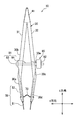
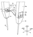
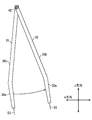
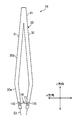
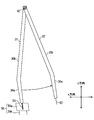
- the inspection apparatus 10 includes a main body portion 30, a probe 50, and a bridging portion 70.
- the main body 30 is held by a user with a hand or the like.
- the main body 30 has a shape that the user holds with one hand.
- the main body 30 can be elastically deformed by a user operation.
- the main body 30 is provided with a plurality of probes 50. The relative distance of the plurality of probes 50 varies due to elastic deformation of the main body 30 by the user.
- the tip of the probe 50 is brought into contact with a noise verification site on the circuit board.
- the bridging part 70 electrically connects a plurality of probes 50.
- the bridging unit 70 includes a noise countermeasure element 74 such as a capacitor.
- the noise countermeasure element 74 is electrically connected to the plurality of probes 50. Therefore, when the two probes 50 are brought into contact with the noise verification site, the bypass path constituted by the two probes 50 and the bridge portion 70 is connected to the noise verification site.
- the noise countermeasure element 74 is connected in series to this bypass path. For this reason, a bypass circuit comprising a bypass path and a noise countermeasure element 74 is connected in parallel to the noise verification portion.
- a bypass circuit can be connected in parallel to an arbitrary noise verification portion without changing the design layout of the circuit board.
- the user appropriately selects connection of the inspection apparatus 10 to the circuit board, and the output of the circuit board is verified by a spectrum analyzer or the like each time. By doing so, an increase in the number of man-hours accompanying the change in the design layout is suppressed.
- the noise countermeasure elements 74 of the plurality of inspection apparatuses 10 may be different. Further, in the process of creating the circuit board, the inspection apparatus 10 is connected to the wiring board instead of the electronic element. By doing so, the design layout of the circuit board may be verified.
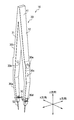
- the main body 30 of the inspection apparatus 10 includes a first grip part 31, a second grip part 32, and a connection part 41.
- the forming material of each of the first grip portion 31, the second grip portion 32, and the connecting portion 41 is an elastic body.
- This elastic body is an insulating resin.
- the main body 30 is manufactured by injection molding or the like.
- the 1st holding part 31, the 2nd holding part 32, and the connection part 41 are integral.
- the connection portion 41 is surrounded by a broken line in order to avoid the boundary between the first grip portion 31, the second grip portion 32, and the connection portion 41 from becoming unknown.
- the connecting part 41 corresponds to a first connecting part.
- first grip portion 31 and the second grip portion 32 are integrally connected by a connecting portion 41. Thereby, each of the first gripping portion 31 and the second gripping portion 32 is cantilevered by the connecting portion 41, and the tip thereof is a free end. The tips of the first gripping part 31 and the second gripping part 32 are spaced apart in the x direction.
- the main body 30 of the present embodiment has the same shape as so-called tweezers.
- the user grasps the first grip portion 31 and the second grip portion 32 with one hand, and elastically deforms the main body portion 30 so that the tips of the first grip portion 31 and the second grip portion 32 approach each other.
- the user elastically deforms the main body 30 so that the tips of the first grip portion 31 and the second grip portion 32 are separated from each other. As a result, the distance between the tips of the first grip portion 31 and the second grip portion 32 varies.
- a probe 50 is provided at the tip of each of the first grip portion 31 and the second grip portion 32. Due to the elastic deformation of the main body 30 described above, the relative positions of the probes 50 of the first grip portion 31 and the second grip portion 32 vary. As a result, the distance between the tips of the two probes 50 in contact with the circuit board varies.
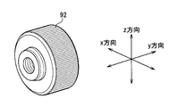
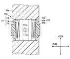
- the probe 50 has an electrical contact 51 and a conductive portion 52.
- the electrical contact 51 has a contact terminal 53, a spring 54, and a cylindrical portion 55.
- the cylinder portion 55 has a cylindrical shape having a bottom.
- a contact terminal 53 is inserted into the hollow of the cylindrical portion 55 together with the spring 54.
- the contact terminal 53 and the cylindrical portion 55 are electrically and mechanically connected via a spring 54.
- the spring 54 is elastically deformed.
- the contact terminal 53 is movable so as to be inserted into and removed from the hollow of the cylindrical portion 55.
- the spring 54 is indicated by a broken line in order to indicate that the spring 54 is in the cylindrical portion 55.
- the spring 54 contracts. As a result, the spring 54 imparts a restoring force toward the circuit board to the contact terminal 53. The tip of the contact terminal 53 is pressed against the circuit board by this restoring force. This ensures contact between the contact terminal 53 and the circuit board. The electrical connection between the electrical contact 51 and the circuit board is stabilized.
- the conductive portion 52 has an inner diameter wider than the outer diameter of the cylindrical portion 55.
- a stopper 52 a is formed in the hollow of the conductive portion 52.
- the separation distance between the stopper 52 a and the opening of the conductive portion 52 is equal to the cylindrical portion 55.
- the cylindrical portion 55 is inserted into the hollow portion of the conductive portion 52 until the end portion of the cylindrical portion 55 contacts the stopper 52a. Then, the cylindrical portion 55 is accommodated in the conductive portion 52, and the contact terminal 53 protrudes from the opening portion of the conductive portion 52.
- the conductive portion 52 and the cylindrical portion 55 are in contact with each other and are electrically connected to each other. As a result, the conductive portion 52 and the contact terminal 53 are electrically connected via the cylindrical portion 55 and the spring 54.
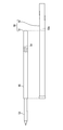
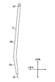
- the impedance of the probe 50 changes according to the elastic deformation of the spring 54 due to the application of stress to the contact terminal 53. That is, the impedance changes according to the length L of the probe 50 shown in FIG.
- the impedance also changes depending on the distance W between the two probes 50 connected by the bridging portion 70.
- the resonance point of the resonance circuit constituted by the bypass circuit changes.
- the stopper 52 a is indicated by a broken line in order to indicate that the stopper 52 a is in the conductive portion 52.
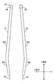
- each of the first grip portion 31 and the second grip portion 32 includes a free end portion 30 a provided with a contact terminal 53 of the probe 50, and a fixed end portion that connects the free end portion 30 a and the connecting portion 41. 30b.
- Each of the free end 30a and the fixed end 30b has a linear shape extending in one direction. However, the extending directions of the free end 30a and the fixed end 30b are different. Therefore, the free end portion 30a and the fixed end portion 30b are crossed and connected.
- One end of the fixed end portion 30b is connected to the connecting portion 41, and the other end is integrally connected to one end of the free end portion 30a.
- the other end of the free end portion 30a is the tip (free end) of the grip portion.
- One end of the fixed end portion 30b of each of the first grip portion 31 and the second grip portion 32 is fixed to the connecting portion 41.
- the fixed end portions 30b of the first grip portion 31 and the second grip portion 32 face each other in the x direction.
- the separation distance in the x direction between the fixed end portion 30b of the first gripping portion 31 and the fixed end portion 30b of the second gripping portion 32 gradually increases as the distance from the connecting portion 41 increases along the z direction.
- the fixed end portion 30b of the first gripping portion 31 and the fixed end portion 30b of the second gripping portion 32 are widened toward the free end portion 30a side from the connecting portion 41 side in the z direction.
- the free end portions 30a of the first grip portion 31 and the second grip portion 32 face each other in the x direction.
- the distance in the x direction between the free end portion 30a of the first gripping portion 31 and the free end portion 30a of the second gripping portion 32 gradually decreases in the z direction from the connecting portion 41 side toward the probe 50 side. Yes.
- the separation distance in the x direction of the other end of the free end portion 30a of each of the first grip portion 31 and the second grip portion 32 is different from that of the fixed end portion 30b of each of the first grip portion 31 and the second grip portion 32. It is shorter than the separation distance in the x direction at the end.
- an insertion hole 30c for inserting and fixing the probe 50 is formed in the free end portion 30a and the fixed end portion 30b.
- the insertion hole 30c is formed along the direction in which the free end 30a extends from the connecting portion between the free end 30a and the fixed end 30b toward the other end (tip) of the free end 30a.
- the insertion hole 30c is opened at each of the connecting portion and the tip.
- the probe 50 is inserted with the contact terminal 53 as the head from the opening at the connection portion of the insertion hole 30c toward the opening at the tip.
- the conductive portion 52 is accommodated in the insertion hole 30c, and the contact terminal 53 protrudes from the tip of the free end portion 30a.
- the opening on the connection site side of the insertion hole 30c is closed with resin or the like.
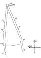
- the bridging part 70 electrically connects the probe 50 of the first grip part 31 and the probe 50 of the second grip part 32.
- the bridging unit 70 includes a flexible substrate 71, a first wiring substrate 72, a second wiring substrate 73, and a noise countermeasure element 74.
- the bridging portion 70 corresponds to the second connecting portion.
- the flexible substrate 71 has flexibility.
- the flexible substrate 71 is a flexible substrate.
- the flexible substrate 71 has a first wiring pattern 75. As shown in FIGS. 4 and 5, the flexible substrate 71 has a shape extending in the x direction. The center of the flexible substrate 71 is curved so as to protrude toward the connecting portion 41 side. Therefore, the flexible substrate 71 is easily elastically deformed in the x direction.
- a first wiring substrate 72 is connected to one end of the flexible substrate 71.
- a second wiring substrate 73 is connected to the other end of the flexible substrate 71.
- Each of the first wiring board 72 and the second wiring board 73 is made of a material harder than the flexible board 71.
- the first wiring board 72 and the second wiring board 73 are glass epoxy boards.
- the first wiring board 72 and the second wiring board 73 have a second wiring pattern 76.
- the second wiring pattern 76 is electrically connected to the first wiring pattern 75 via solder or the like.
- Each of the first wiring board 72 and the second wiring board 73 has a shape extending in the x direction. One end of each of the first wiring substrate 72 and the second wiring substrate 73 is connected to the flexible substrate 71. The other ends of the first wiring board 72 and the second wiring board 73 are connected to the conductive portion 52.
- the lower surface of the flexible substrate 71 is connected to the upper surfaces of the respective ends of the first wiring substrate 72 and the second wiring substrate 73. Thereby, the end surface of each end of the first wiring board 72 and the second wiring board 73 is separated in the x direction. In the present embodiment, at least a part of one end face of each of the first wiring board 72 and the second wiring board 73 is opposed to each other in the x direction.
- each of the first wiring board 72 and the second wiring board 73 is notched. Thereby, the other end of each of the first wiring board 72 and the second wiring board 73 has a bifurcated shape.
- a lateral hole 30d communicating with the insertion hole 30c is formed in the free end portion 30a of each of the first grip portion 31 and the second grip portion 32.
- the horizontal hole 30d is formed along the x direction.
- An insertion hole 30c is opened in the upper surface and the lower surface that intersect the extending direction of the free end 30a among the four surfaces forming the horizontal hole 30d. Therefore, the conductive portion 52 of the probe 50 inserted into the insertion hole 30c penetrates the upper surface and the lower surface of the horizontal hole 30d. Thereby, a part of the conductive portion 52 is provided in the horizontal hole 30d.
- the horizontal hole 30d is open on the surface of the first grip portion 31 and the second grip portion 32 facing each other and on the opposite surface, but the opening area of the facing surface is larger than the opening area of the opposite surface. Is also narrower.
- the upper surface that forms the horizontal hole 30d has a slope shape that gradually moves away from the lower surface that forms the horizontal hole 30d as it goes from the opposite surface to the opposite surface.
- the conductive portion 52 provided in the lateral hole 30d of the first gripping portion 31 is in contact with the end surface between the bifurcated portions of the end portion of the first wiring board 72.
- the conductive portion 52 and the second wiring pattern 76 of the first wiring board 72 are electrically connected via solder.
- the first wiring board 72 is fixed to the lower surface forming the horizontal hole 30d by an adhesive.
- the conductive portion 52 provided in the lateral hole 30 d of the second gripping portion 32 is in contact with the end surface between the two divided portions of the end portion of the second wiring board 73.
- the conductive portion 52 and the second wiring pattern 76 of the second wiring board 73 are electrically connected via solder.
- the second wiring board 73 is fixed to the lower surface forming the horizontal hole 30d with an adhesive.
- the noise countermeasure element 74 is provided on the first wiring board 72. A part of the second wiring pattern 76 of the first wiring board 72 provided with the noise countermeasure element 74 is removed, and the electrical connection is cut off. The noise countermeasure element 74 is fixed to the first wiring board 72 with solder so as to bridge and connect the second wiring pattern 76 that has been disconnected electrically. A part of the noise countermeasure element 74 is provided in the lateral hole 30 d of the first grip portion 31.
- a bypass circuit is configured by the probe 50 of the first gripping portion 31, the noise countermeasure element 74, the bridging portion 70, and the probe 50 of the second gripping portion 32.
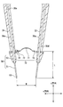
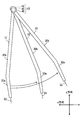
- the inspection apparatus 10 includes a position defining section 90 that defines the relative positions of the probes 50 of the first gripping section 31 and the second gripping section 32 in addition to the main body section 30, the probe 50, and the bridging section 70.
- the position defining portion 90 includes a connecting screw 91 shown in FIG. 1 and a nut 92 shown in FIGS. 1 and 6.
- a regulation hole 30 e for inserting the connection screw 91 is formed in the fixed end portion 30 b of each of the first grip portion 31 and the second grip portion 32.
- the regulation hole 30e is formed along the direction in which the first grip portion 31 and the second grip portion 32 face each other.
- the defining hole 30e is formed along the x direction.
- the defining hole 30e is opened on each of the first gripping portion 31 and the second gripping portion 32 facing each other (hereinafter referred to as an inner surface) and the outer surface on the opposite side.
- a screw groove is formed in the specified hole 30e of the first grip portion 31.
- the connecting screw 91 is fastened to the specified hole 30e of the first grip portion 31.
- the connecting screw 91 has a screw head 93 and a screw shaft 94.
- a screw head 93 is integrally connected to the end of the screw shaft 94.
- the connecting screw 91 is inserted into the defining hole 30e of each of the first grip portion 31 and the second grip portion 32 so that the screw head 93 comes into contact with the outer surface of the first grip portion 31.
- the tip of the screw shaft 94 is inserted through the defining hole 30 e of the second grip portion 32.
- the diameter of the specified hole 30e of the second grip portion 32 is longer than that of the screw shaft 94.
- the connection screw 91 and the inner wall surface forming the defining hole 30e of the second gripping portion 32 are not in contact with each other due to elastic deformation of the main body portion 30.
- the nut 92 is attached to the tip end of the screw shaft 94 that protrudes outward from the specified hole 30 e of the second grip portion 32. Therefore, the fixed end portions 30 b of the first grip portion 31 and the second grip portion 32 are positioned between the screw head 93 and the nut 92.
- the attachment position of the nut 92 to the connection screw 91 is variable in the axial direction of the connection screw 91. By adjusting the attachment position of the nut 92 to the screw shaft 94, the maximum separation distance between the first grip portion 31 and the second grip portion 32 is defined.
- the first wiring board 72 and the second wiring board 73 As shown in the column (c) of FIG. 7, when the main body 30 is deformed by the user so that the tips of the first gripping portion 31 and the second gripping portion 32 approach each other, the first wiring board 72 and the second wiring board 73. The end faces of one end of each contact. Thereby, the minimum separation distance between the first grip portion 31 and the second grip portion 32 is defined.
- the deformation of the main body 30 causes the flexible substrate 71 to deform so as to shrink.
- the contraction of the flexible substrate 71 is defined by the contact between the first wiring substrate 72 and the second wiring substrate 73. Due to the contact between the first wiring board 72 and the second wiring board 73, the contact between the probe 50 of the first holding part 31 and the probe 50 of the second holding part 32 is avoided.
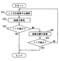
- step S10 the user selects the noise countermeasure element 74.
- the inspection apparatus 10 of the present embodiment has a configuration in which a bridging portion 70 provided with a noise countermeasure element 74 is connected to the main body 30 by solder. Therefore, the user prepares a plurality of inspection apparatuses 10 having different noise countermeasure elements 74, and selects one provided with the noise countermeasure elements 74 used for noise verification from the plurality of inspection apparatuses 10. After this, the user proceeds to step S20.
- the user selects the noise countermeasure element 74 used for noise verification in step S10, It is attached to the inspection device 10.
- step S20 the user grasps the main body 30 and elastically deforms the main body 30 according to the noise verification part of the circuit board. That is, the user grasps the first grip portion 31 and the second grip portion 32 with his / her hand so that the tips of the first grip portion 31 and the second grip portion 32 approach each other according to the noise verification site of the circuit board, or The main body 30 is elastically deformed so as to be separated from each other. Thereby, the relative distance of the contact terminal 53 of the probe 50 provided in each of the first grip portion 31 and the second grip portion 32 is changed. The user presses the tip of the contact terminal 53 against the noise verification site. By doing so, the spring 54 of the probe 50 is elastically deformed, and the electrical connection between the contact terminal 53 and the noise verification portion is stabilized by the restoring force of the spring 54. After this, the user proceeds to step S30.
- step S30 the user determines whether or not the electromagnetic noise included in the output of the circuit board has been reduced by a spectrum analyzer or the like. If the electromagnetic noise has decreased below the user's desired value, the noise verification ends. On the other hand, if the electromagnetic noise has not decreased below the desired value, the user proceeds to step S40.
- step S40 the user changes the contact position between the inspection apparatus 10 and the circuit board. That is, the user changes the noise verification part. After this, the user proceeds to step S50.
- step S50 the user determines whether or not electromagnetic noise included in the output of the circuit board has been reduced by using a spectrum analyzer or the like. If the electromagnetic noise is reduced below the desired value, the noise verification is finished. On the other hand, if the electromagnetic noise has not decreased below the desired value, the user returns to step S10. Then, the user repeats the processing from step S10 to step S50 again. As described above, the reduction of electromagnetic noise is verified by changing the inspection device 10 or the contact position of the inspection device 10 without changing the design layout of the circuit board.
- the inspection apparatus 10 includes the main body 30 and the probe 50.
- the main body 30 includes a first grip part 31, a second grip part 32, and a connection part 41. These 1st holding parts 31, the 2nd holding part 32, and the connection part 41 consist of the same elastic body.
- the end portions of the first grip portion 31 and the second grip portion 32 are integrally connected by a connecting portion 41. As a result, the main body 30 is elastically deformed, so that the spacing between the tips of the first grip portion 31 and the second grip portion 32 varies.
- a probe 50 is provided in each of the first grip portion 31 and the second grip portion 32. Therefore, the relative positions of the probes 50 of the first grip portion 31 and the second grip portion 32 can be changed by elastic deformation of the main body portion 30.
- the inspection apparatus 10 has a bridging portion 70.
- the bridging portion 70 has a noise countermeasure element 74, and the probes 50 of the first gripping portion 31 and the second gripping portion 32 are electrically connected by the bridging portion 70. According to this, it is possible to verify the increase or decrease of the electromagnetic noise of the circuit board without changing the design layout of the circuit board. Therefore, the noise verification time can be shortened.
- the end portions of the first grip portion 31 and the second grip portion 32 are integrally connected by a connecting portion 41. According to this, unlike the configuration in which, for example, the central portions of the plurality of gripping portions are connected by the connecting portion, the connecting portion between the first gripping portion 31, the second gripping portion 32, and the connecting portion 41 is determined by the user. It is suppressed that operation of the 1 grip part 31 and the 2nd grip part 32 becomes obstructed.
- the electrical contact 51 of the probe 50 has a contact terminal 53 and a spring 54, and the spring 54 is elastically deformed by the pressure along the extending direction of the contact terminal 53. According to this, the contact state between the contact terminal 53 and the circuit board is ensured by the restoring force of the spring 54. As a result, the electrical connection between the electrical contact 51 and the circuit board is stabilized.
- the bridging portion 70 includes a flexible substrate 71, a first wiring substrate 72, a second wiring substrate 73, and a noise countermeasure element 74.
- the flexible substrate 71 has flexibility and its center is curved.
- a first wiring substrate 72 and a second wiring substrate 73 that are harder than the flexible substrate 71 are connected to both ends of the flexible substrate 71.
- a noise countermeasure element 74 is mounted on the first wiring board 72.
- the first wiring board 72 is fixed to the first holding part 31, and the second wiring board 73 is fixed to the second holding part 32.
- the noise countermeasure element 74 and the noise countermeasure element 74 are bridged by deformation of the flexible substrate 71 due to a change in the relative position of the first grip portion 31 and the second grip portion 32.
- the connection with the unit 70 is prevented from becoming unstable.
- the maximum distance between the first grip portion 31 and the second grip portion 32 is defined by the position defining portion 90. Thereby, the elongation of the flexible substrate 71 of the bridging portion 70 is defined. Therefore, damage to the bridging portion 70 due to the separation between the first grip portion 31 and the second grip portion 32 is suppressed.
- the minimum distance between the first gripping portion 31 and the second gripping portion 32 is defined by the contact between the end faces of one end of the first wiring board 72 and the second wiring board 73 included in the bridging portion 70.
- a part of the noise countermeasure element 74 is provided in the lateral hole 30 d of the first grip portion 31. According to this, it is suppressed that force is applied to the noise countermeasure element 74 from the outside. Therefore, the connection between the noise countermeasure element 74 and the bridging portion 70 is suppressed from becoming unstable. It is also possible to employ a configuration in which all of the noise countermeasure elements 74 are provided in the lateral hole 30d.
- the connecting portion 41 an example in which the end portions of the first gripping portion 31 and the second gripping portion 32 are integrally connected by the connecting portion 41 has been described.
- the separate end portions of the first grip portion 31 and the second grip portion 32 are connected to each other by a connecting screw 42 so as to be rotatable.
- the connecting screw 42 corresponds to the first connecting portion.
- FIG. 9 shows the first grip portion 31. Since the second grip 32 has the same configuration as the first grip 31, the description thereof is omitted.
- a connecting hole 30f along the y direction is formed at one end of each of the fixed end portions 30b of the first grip portion 31 and the second grip portion 32.
- a connection screw 42 is passed through the connection hole 30f.
- the first gripping portion 31 and the second gripping portion 32 can rotate about the connecting screw 42.
- illustration of the bridging portion 70 and the position defining portion 90 is omitted.
- the relative position of the probe 50 between the first gripper 31 and the second gripper 32 can be changed by rotating the first gripper 31 and the second gripper 32.
- the inspection apparatus 10 includes the same components as the inspection apparatus 10 described in the first embodiment. Therefore, it cannot be overemphasized that there exists an equivalent effect. The same applies to each embodiment described below. Therefore, the description is omitted.
- the end portions of the separate first gripping portion 31 and second gripping portion 32 are rotatably connected by the connecting screw 42 .
- the end portions of the first grip portion 31 and the second grip portion 32 can be rotated by the ball joints 43 formed at the end portions of the first grip portion 31 and the second grip portion 32, respectively. It is the composition connected to.
- the ball joint 43 corresponds to the first connecting portion.
- the ball joint 43 has a sphere portion 44 and a spherical shell portion 45.
- the spherical portion 44 has a spherical shape as the name suggests.
- the spherical shell portion 45 has a spherical shell shape as the name suggests.
- the spherical portion 44 is formed at one end of the fixed end portion 30 b of the first grip portion 31.
- the spherical shell portion 45 is formed at one end of the fixed end portion 30 b of the second grip portion 32.
- the spherical shell portion 45 is formed with a notch for inserting the spherical portion 44 therein.
- the spherical body portion 44 is inserted into the spherical shell portion 45 through the notch. Thereby, the 1st holding part 31 and the 2nd holding part 32 are connected.
- the inner diameter of the spherical shell portion 45 is equal to or slightly longer than the diameter of the spherical portion 44.
- the inner diameter of the spherical shell portion 45 is set so that the spherical portion 44 can slide relative to the spherical shell portion 45.
- the first grip portion 31 and the second grip portion 32 can rotate about the ball joint 43.
- the relative position of the probe 50 between the first grip portion 31 and the second grip portion 32 can be changed.
- illustration of the bridging portion 70 and the position defining portion 90 is omitted.
- the inspection apparatus 10 may not include the position defining unit 90.
- the spherical shell portion 45 can be removed from the spherical portion 44. That is, the first grip 31 can be attached to and detached from the spherical shell 45 of the second grip 32. In other words, the second grip 32 can be attached to and detached from the sphere 44 of the first grip 31. According to this, even if a failure occurs in the first grip portion 31 or the second grip portion 32, the failed grip portion can be replaced.
- the inspection apparatus 10 includes the third gripping portion 33 in addition to the first gripping portion 31 and the second gripping portion 32, the third gripping portion 33 is replaced with the first gripping portion 31 and the second gripping portion.
- Each of the 32 can be rotatably connected.
- the ball joint 43 includes the spherical body portion 44, the first spherical shell portion 45, and the second spherical shell portion. Part 46.
- the second spherical shell portion 46 is formed at one end of the fixed end portion 30 b of the third gripping portion 33.
- the inner diameter of the second spherical shell portion 46 is set so that the first spherical shell portion 45 can slide relative to the second spherical shell portion 46.
- the second spherical shell portion 46 is formed with a notch for inserting the first spherical shell portion 45 therein.
- the first spherical shell portion 45 is inserted into the second spherical shell portion 46 together with the spherical portion 44 through this notch. Thereby, the 1st holding part 31, the 2nd holding part 32, and the 3rd holding part 33 are connected.
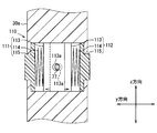
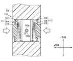
- the inspection apparatus 10 includes the clamping unit 110.
- the clamping part 110 corresponds to a second connecting part.
- the clamping unit 110 functions to clamp the lead 77 of the noise countermeasure element 74 and fix it to the main body unit 30.
- the clamping part 110 is provided at the free end part 30 a of each of the first grip part 31 and the second grip part 32. More specifically, the clamping part 110 is provided in the horizontal hole 30d of the free end part 30a.
- the clamping unit 110 includes a first clamping unit 111 and a second clamping unit 112.
- Each of the first clamping part 111 and the second clamping part 112 has a plate part 113, a spring 114, and a pressing part 115.
- Each of the plate portion 113 and the spring 114 is provided in the lateral hole 30d.
- a part of the pressing part 115 is provided in the horizontal hole 30d.
- the plate portion 113 is located on the center side of the lateral hole 30d.
- the plate portion 113 and the pressing portion 115 are connected via a spring 114.
- the spring 114 is elastically deformable in the y direction.
- the plate portion 113 is made of a conductive material and is electrically connected to the conductive portion 52.
- a window for exposing a part of the pressing portion 115 to the outside is formed on each of the left and right surfaces between the upper surface and the lower surface of the horizontal hole 30d.
- the pressing part 115 of the first clamping part 111 is provided in the left window.
- the pressing part 115 of the second clamping part 112 is provided in the right window.
- the plate part 113 of the 1st clamping part 111 and the plate part 113 of the 2nd clamping part 112 are provided in the center side of the horizontal hole 30d in the aspect arranged in the x direction.
- first clamping unit 111 is positioned above the paper surface and the second clamping unit 112 is positioned below the paper surface, a portion hidden by the first clamping unit 111 in the second clamping unit 112 is shown. It is indicated by a broken line.
- a sandwiching hole 113a penetrating in the x direction is formed in each plate portion 113 of the first sandwiching portion 111 and the second sandwiching portion 112.
- the holding hole 113 a has a diameter longer than that of the lead 77.
- the lead 77 of the noise countermeasure element 74 is inserted into the clamping hole 113a of each of the first clamping part 111 and the second clamping part 112.
- the clamping holes 113a of the first clamping part 111 and the second clamping part 112 overlap each other in the x direction. More specifically, the center sides of the lateral holes 30d of the clamping holes 113a of the first clamping part 111 and the second clamping part 112 overlap each other in the x direction.
- a through hole penetrating in the x direction is formed by the overlap of the two holding holes 113a. The interval between the through holes in the y direction is shorter than the diameter of the lead 77.
- the lead 77 is inserted into the through hole formed by the two holding holes 113a. Then, the plate part 113 moves against the restoring force of the spring 114 so that the through hole is widened. Specifically, the plate portion 113 of the first clamping unit 111 moves to the right side along the y direction as indicated by a solid arrow. The plate portion 113 of the second sandwiching portion 112 moves to the left side along the y direction as indicated by the dashed arrow. Thereby, the restoring force which tries to move to the left surface side arises in the spring 114 of the 1st clamping part 111. FIG. The spring 114 of the second clamping unit 112 has a restoring force that tends to move to the right side.
- the lead 77 Due to the restoring forces opposite to each other, the lead 77 is clamped by the annular end surfaces forming the clamping holes 113a of the two plate portions 113, respectively. As a result, the lead 77 and the plate portion 113 are mechanically and electrically connected. As a result, the noise countermeasure element 74 and the probe 50 are electrically connected via the lead 77 and the plate portion 113.
- the portion protruding from the lateral hole 30 d in the pressing portion 115 of each of the first sandwiching portion 111 and the second sandwiching portion 112 is pressed toward the center of the lateral hole 30 d.
- the plate part 113 of the 1st clamping part 111 is moved to the right surface side along ay direction as shown by the solid line arrow.
- the plate portion 113 of the second sandwiching portion 112 is moved to the left side along the y direction as indicated by a broken line arrow.
- the through hole is widened to release the contact between the lead 77 and the annular end surface forming the clamping hole 113a.
- the lead 77 is removed from the clamping hole 113a.
- the holding of the lead 77 by the holding unit 110 is released.
- the lead 77 is inserted into the through hole in a state where the pressing portion 115 is pressed to widen the through hole. Thereafter, the pressing to the pressing portion 115 is released. Thus, the lead 77 may be clamped by the clamping unit 110.
- the noise countermeasure element 74 having the lead 77 can be attached to and detached from the inspection apparatus 10. Therefore, noise verification can be performed by preparing capacitors having different capacities as the noise countermeasure element 74 and selecting the capacitors appropriately and connecting them to the inspection apparatus 10.
- FIG. 18 As the connection structure between the free end portion 30a and the fixed end portion 30b, for example, the configuration shown in FIG. 18 can be adopted.
- a screw groove 30g is formed at one end of the free end 30a and the other end of the fixed end 30b.
- One end of the free end portion 30a has a convex screw shape.
- the other end of the fixed end 30b has a concave screw shape.
- the screw groove 30g is formed around the axial direction (extending direction) of the free end 30a.
- the free end 30a and the fixed end 30b can be fixed by screwing one end of the free end 30a to the other end of the fixed end 30b. Conversely, by releasing the screw fastening, it is possible to release the fixation between the free end 30a and the fixed end 30b. Furthermore, the free end 30a can be moved in the extending direction with respect to the fixed end 30b by adjusting the screw tightening degree between the free end 30a and the fixed end 30b. According to this, the connection position of the probe 50 provided in the free end 30a and the circuit board can be adjusted.
- a plurality of annular grooves orthogonal to the axial direction of the free end 30a may be formed at one end of the free end 30a and the other end of the fixed end 30b. That is, in FIG. 18, an annular groove may be formed at one end of the free end portion 30 a and the other end of the fixed end portion 30 b instead of a spiral shape like a screw groove. According to this, the free end portion 30a is pushed in the extending direction with respect to the fixed end portion 30b or pulled to adjust the position of the groove in which the free end portion 30a and the fixed end portion 30b are fitted to each other. The free end 30a can be moved in the extending direction with respect to the fixed end 30b.
- the spherical body part 44 is formed in the end of the fixed end part 30b of the 1st holding part 31, and the spherical shell part 45 shows the example formed in the end of the fixed end part 30b of the 2nd holding part 32. It was. However, as shown in FIG. 18, a configuration in which the sphere portion 44 is connected to one end of the fixed end portion 30 b of the first grip portion 31 may be employed. Although not shown, a configuration in which the spherical shell portion 45 is connected to one end of the fixed end portion 30b of the second gripping portion 32 may be employed.
- the collar part 47 for fitting and connecting each other to the one end of the fixed end part 30b and the support part 44a of the spherical body part 44 is formed.
- the noise countermeasure element 74 is electrically connected to the second wiring pattern 76 of the first wiring board 72 via the solder and fixed to the first wiring board 72.
- a noise countermeasure element 74 may be formed on the first wiring substrate 72 together with the second wiring pattern 76, as schematically shown in FIG.
- the noise countermeasure element 74 may be formed on the flexible substrate 71 together with the first wiring pattern 75.
- the wiring length tends to be long. Therefore, there is a concern about an increase in impedance of the inspection apparatus 10. Therefore, in the case of this modification, the size of the inspection apparatus 10 can be such that it can be operated with one hand, but more preferably it can be operated with a finger.
- the inspection apparatus 10 may have a conductive terminal portion 56 connected to the contact terminal 53 of the probe 50 as shown in FIG.
- the terminal portion 56 has a main body portion 56 a that is electrically connected to the contact terminal 53 and has a fixing hole for fixing the contact terminal 53.
- the terminal portion 56 has a plurality of terminal contacts 56b connected to the main body portion 56a, which function as a plurality of new contact terminals.
- the terminal contact 56b may be thicker or thinner than the contact terminal 53 as shown in FIGS. According to this, a plurality of terminals can be electrically connected by one contact terminal 53.
- a capacitor is shown as a specific example of the noise countermeasure element 74.
- the noise countermeasure element 74 is not limited to the above example, and a general passive element can be adopted.
- a resistor, an inductor, a common mode choke coil, or the like can be employed as the noise countermeasure element 74.
- the inspection apparatus 10 has two gripping portions.
- the inspection apparatus 10 may have three or more gripping units.
- the configuration having three or more gripping portions is particularly useful in the configurations of the second embodiment and the third embodiment.
- the connecting portion 41 for example, in the first embodiment, the example in which the end portions of the first gripping portion 31 and the second gripping portion 32 are connected by the connecting portion 41 is shown. However, a configuration in which the central portions of the first gripping portion 31 and the second gripping portion 32 are connected by the connecting portion 41 may be employed. In addition, instead of the connecting portion 41, for example, a configuration in which the center portions of the first gripping portion 31 and the second gripping portion 32 are connected by the connecting screw 42 shown in the second embodiment may be employed.
Landscapes
- Physics & Mathematics (AREA)
- General Physics & Mathematics (AREA)
- Measuring Leads Or Probes (AREA)
Applications Claiming Priority (2)
| Application Number | Priority Date | Filing Date | Title |
|---|---|---|---|
| JP2017116208A JP6743768B2 (ja) | 2017-06-13 | 2017-06-13 | 検査装置 |
| JP2017-116208 | 2017-06-13 |
Publications (1)
| Publication Number | Publication Date |
|---|---|
| WO2018230085A1 true WO2018230085A1 (ja) | 2018-12-20 |
Family
ID=64659624
Family Applications (1)
| Application Number | Title | Priority Date | Filing Date |
|---|---|---|---|
| PCT/JP2018/012263 Ceased WO2018230085A1 (ja) | 2017-06-13 | 2018-03-27 | 検査装置 |
Country Status (2)
| Country | Link |
|---|---|
| JP (1) | JP6743768B2 (enExample) |
| WO (1) | WO2018230085A1 (enExample) |
Cited By (1)
| Publication number | Priority date | Publication date | Assignee | Title |
|---|---|---|---|---|
| WO2019138853A1 (ja) * | 2018-01-09 | 2019-07-18 | 株式会社デンソー | 検査装置 |
Citations (7)
| Publication number | Priority date | Publication date | Assignee | Title |
|---|---|---|---|---|
| JPS5884569U (ja) * | 1981-12-01 | 1983-06-08 | 株式会社精工舎 | テスタの測定棒 |
| JPS6095562U (ja) * | 1983-12-07 | 1985-06-29 | 大阪ヒユーズ株式会社 | 電気回路測定用片手持ち端子棒 |
| JPH0415067U (enExample) * | 1990-05-28 | 1992-02-06 | ||
| JPH08226934A (ja) * | 1995-02-22 | 1996-09-03 | Nippon Telegr & Teleph Corp <Ntt> | プローブ |
| JPH10104268A (ja) * | 1996-09-25 | 1998-04-24 | Nippon Dempa Kogyo Co Ltd | テスト棒 |
| US6276956B1 (en) * | 1999-04-12 | 2001-08-21 | Sencore, Inc. | Dual point test probe for surface mount type circuit board connections |
| JP2004170360A (ja) * | 2002-11-22 | 2004-06-17 | Kanto Tsusoku Kiki Kk | 積層型プローブ及び接触子 |
-
2017
- 2017-06-13 JP JP2017116208A patent/JP6743768B2/ja active Active
-
2018
- 2018-03-27 WO PCT/JP2018/012263 patent/WO2018230085A1/ja not_active Ceased
Patent Citations (7)
| Publication number | Priority date | Publication date | Assignee | Title |
|---|---|---|---|---|
| JPS5884569U (ja) * | 1981-12-01 | 1983-06-08 | 株式会社精工舎 | テスタの測定棒 |
| JPS6095562U (ja) * | 1983-12-07 | 1985-06-29 | 大阪ヒユーズ株式会社 | 電気回路測定用片手持ち端子棒 |
| JPH0415067U (enExample) * | 1990-05-28 | 1992-02-06 | ||
| JPH08226934A (ja) * | 1995-02-22 | 1996-09-03 | Nippon Telegr & Teleph Corp <Ntt> | プローブ |
| JPH10104268A (ja) * | 1996-09-25 | 1998-04-24 | Nippon Dempa Kogyo Co Ltd | テスト棒 |
| US6276956B1 (en) * | 1999-04-12 | 2001-08-21 | Sencore, Inc. | Dual point test probe for surface mount type circuit board connections |
| JP2004170360A (ja) * | 2002-11-22 | 2004-06-17 | Kanto Tsusoku Kiki Kk | 積層型プローブ及び接触子 |
Cited By (1)
| Publication number | Priority date | Publication date | Assignee | Title |
|---|---|---|---|---|
| WO2019138853A1 (ja) * | 2018-01-09 | 2019-07-18 | 株式会社デンソー | 検査装置 |
Also Published As
| Publication number | Publication date |
|---|---|
| JP6743768B2 (ja) | 2020-08-19 |
| JP2019002746A (ja) | 2019-01-10 |
Similar Documents
| Publication | Publication Date | Title |
|---|---|---|
| KR101415722B1 (ko) | 콘택트 프로브 및 프로브 유닛 | |
| JP6711469B2 (ja) | プローブ | |
| JP6395936B2 (ja) | テストソケット | |
| KR102240208B1 (ko) | 검사 지그, 및 검사 장치 | |
| JP6647451B2 (ja) | コンタクトプローブおよびプローブユニット | |
| US11940465B2 (en) | Contact probe and signal transmission method | |
| JP6367249B2 (ja) | プローブユニット | |
| JP6473364B2 (ja) | プローブユニット | |
| CN113167815B (zh) | 探针单元 | |
| JP7095753B2 (ja) | プローブ | |
| CN112600006A (zh) | 电触头、电连接结构及电连接装置 | |
| JP7717205B2 (ja) | コンタクトプローブ | |
| WO2018181216A1 (ja) | プローブホルダおよびプローブユニット | |
| WO2018230085A1 (ja) | 検査装置 | |
| JP6359347B2 (ja) | プローブユニットおよびコンタクトプローブ | |
| JP7404468B2 (ja) | コンタクトプローブおよび信号伝送方法 | |
| JP6891819B2 (ja) | 検査装置 | |
| JP7220109B2 (ja) | プローブユニット | |
| JP3595305B2 (ja) | 実装前試験用プローブ | |
| WO2013051674A1 (ja) | プローブユニット | |
| KR200281259Y1 (ko) | 테스트 소켓 | |
| US12055561B2 (en) | Contact terminal, inspection jig, and inspection device | |
| US7238890B2 (en) | PTFE stud for ultrahigh-value resistor and method therefor | |
| JP2005150524A (ja) | 電子制御装置 | |
| JP3147283U (ja) | マイクロ電子コネクタ |
Legal Events
| Date | Code | Title | Description |
|---|---|---|---|
| 121 | Ep: the epo has been informed by wipo that ep was designated in this application |
Ref document number: 18816574 Country of ref document: EP Kind code of ref document: A1 |
|
| NENP | Non-entry into the national phase |
Ref country code: DE |
|
| 122 | Ep: pct application non-entry in european phase |
Ref document number: 18816574 Country of ref document: EP Kind code of ref document: A1 |