WO2018229889A1 - マニピュレータ - Google Patents
マニピュレータ Download PDFInfo
- Publication number
- WO2018229889A1 WO2018229889A1 PCT/JP2017/021932 JP2017021932W WO2018229889A1 WO 2018229889 A1 WO2018229889 A1 WO 2018229889A1 JP 2017021932 W JP2017021932 W JP 2017021932W WO 2018229889 A1 WO2018229889 A1 WO 2018229889A1
- Authority
- WO
- WIPO (PCT)
- Prior art keywords
- wire
- central axis
- disposed
- wall portion
- end effector
- Prior art date
- Legal status (The legal status is an assumption and is not a legal conclusion. Google has not performed a legal analysis and makes no representation as to the accuracy of the status listed.)
- Ceased
Links
Images


Classifications
-
- B—PERFORMING OPERATIONS; TRANSPORTING
- B25—HAND TOOLS; PORTABLE POWER-DRIVEN TOOLS; MANIPULATORS
- B25J—MANIPULATORS; CHAMBERS PROVIDED WITH MANIPULATION DEVICES
- B25J9/00—Program-controlled manipulators
- B25J9/10—Program-controlled manipulators characterised by positioning means for manipulator elements
- B25J9/104—Program-controlled manipulators characterised by positioning means for manipulator elements with cables, chains or ribbons
-
- A—HUMAN NECESSITIES
- A61—MEDICAL OR VETERINARY SCIENCE; HYGIENE
- A61B—DIAGNOSIS; SURGERY; IDENTIFICATION
- A61B17/00—Surgical instruments, devices or methods
- A61B17/28—Surgical forceps
- A61B17/29—Forceps for use in minimally invasive surgery
-
- A—HUMAN NECESSITIES
- A61—MEDICAL OR VETERINARY SCIENCE; HYGIENE
- A61B—DIAGNOSIS; SURGERY; IDENTIFICATION
- A61B34/00—Computer-aided surgery; Manipulators or robots specially adapted for use in surgery
- A61B34/70—Manipulators specially adapted for use in surgery
- A61B34/71—Manipulators operated by drive cable mechanisms
-
- B—PERFORMING OPERATIONS; TRANSPORTING
- B25—HAND TOOLS; PORTABLE POWER-DRIVEN TOOLS; MANIPULATORS
- B25J—MANIPULATORS; CHAMBERS PROVIDED WITH MANIPULATION DEVICES
- B25J19/00—Accessories fitted to manipulators, e.g. for monitoring, for viewing; Safety devices combined with or specially adapted for use in connection with manipulators
- B25J19/0025—Means for supplying energy to the end effector
- B25J19/0029—Means for supplying energy to the end effector arranged within the different robot elements
-
- B—PERFORMING OPERATIONS; TRANSPORTING
- B25—HAND TOOLS; PORTABLE POWER-DRIVEN TOOLS; MANIPULATORS
- B25J—MANIPULATORS; CHAMBERS PROVIDED WITH MANIPULATION DEVICES
- B25J9/00—Program-controlled manipulators
- B25J9/06—Program-controlled manipulators characterised by multi-articulated arms
-
- B—PERFORMING OPERATIONS; TRANSPORTING
- B25—HAND TOOLS; PORTABLE POWER-DRIVEN TOOLS; MANIPULATORS
- B25J—MANIPULATORS; CHAMBERS PROVIDED WITH MANIPULATION DEVICES
- B25J9/00—Program-controlled manipulators
- B25J9/06—Program-controlled manipulators characterised by multi-articulated arms
- B25J9/065—Snake robots
-
- A—HUMAN NECESSITIES
- A61—MEDICAL OR VETERINARY SCIENCE; HYGIENE
- A61B—DIAGNOSIS; SURGERY; IDENTIFICATION
- A61B17/00—Surgical instruments, devices or methods
- A61B17/00234—Surgical instruments, devices or methods for minimally invasive surgery
- A61B2017/00292—Surgical instruments, devices or methods for minimally invasive surgery mounted on or guided by flexible, e.g. catheter-like, means
- A61B2017/003—Steerable
- A61B2017/00305—Constructional details of the flexible means
- A61B2017/00314—Separate linked members
-
- A—HUMAN NECESSITIES
- A61—MEDICAL OR VETERINARY SCIENCE; HYGIENE
- A61B—DIAGNOSIS; SURGERY; IDENTIFICATION
- A61B17/00—Surgical instruments, devices or methods
- A61B17/00234—Surgical instruments, devices or methods for minimally invasive surgery
- A61B2017/00292—Surgical instruments, devices or methods for minimally invasive surgery mounted on or guided by flexible, e.g. catheter-like, means
- A61B2017/003—Steerable
- A61B2017/00318—Steering mechanisms
- A61B2017/00323—Cables or rods
- A61B2017/00327—Cables or rods with actuating members moving in opposite directions
-
- A—HUMAN NECESSITIES
- A61—MEDICAL OR VETERINARY SCIENCE; HYGIENE
- A61B—DIAGNOSIS; SURGERY; IDENTIFICATION
- A61B17/00—Surgical instruments, devices or methods
- A61B17/28—Surgical forceps
- A61B17/29—Forceps for use in minimally invasive surgery
- A61B2017/2926—Details of heads or jaws
- A61B2017/2932—Transmission of forces to jaw members
- A61B2017/2939—Details of linkages or pivot points
-
- A—HUMAN NECESSITIES
- A61—MEDICAL OR VETERINARY SCIENCE; HYGIENE
- A61B—DIAGNOSIS; SURGERY; IDENTIFICATION
- A61B34/00—Computer-aided surgery; Manipulators or robots specially adapted for use in surgery
- A61B34/30—Surgical robots
- A61B2034/305—Details of wrist mechanisms at distal ends of robotic arms
- A61B2034/306—Wrists with multiple vertebrae
Definitions
- the present invention relates to a manipulator.
- a long part is formed by connecting adjacent frames of a plurality of frames arranged in the longitudinal axis direction with a plurality of axes arranged in a twisted positional relationship to each other, and each frame has a longitudinal axis.
- a manipulator is known in which a wire for driving an end effector at the tip is passed through each hole formed so as to penetrate in parallel with the wire, and the wire is arranged along the longitudinal axis (see, for example, Patent Document 1). .
- the present invention has been made in view of the above-described circumstances, and has controllability without causing path length differences in a plurality of wires for driving the end effector even if the long portion is bent in one direction. It aims at providing the manipulator which can be improved.
- One aspect of the present invention is an elongated elongated portion, an end effector disposed at a distal end of the elongated portion, a driving portion disposed at a proximal end of the elongated portion, and power generated in the driving portion.
- a bending portion connected so as to be swingable around a swing axis arranged in a positional relationship, wherein the wire intersects each swing axis at a position radially away from the central axis; It is a manipulator arranged to pass through the position.
- a piece adjacent in one direction along the central axis of the long portion is connected to one piece so as to be swingable about a swing axis perpendicular to the central axis of the long portion,
- a bending portion that can be bent in a plurality of directions is configured by repeatedly connecting other pieces adjacent in the direction so as to be swingable around a swing axis arranged in a twisted positional relationship.
- the wire that transmits power to the end effector provided at the end of the long part is passed through a position that intersects the swing axis that connects the tops so as to be swingable to connect the drive unit and the end effector. Therefore, the path length of the wire is hardly affected by the swing between the frames.
- the bending force only acts on the wire and is not pulled or compressed, so that the path length does not have to be changed.
- the wires so as to pass through the positions intersecting the swing axis at all the swing axes, the path length does not change with respect to the curvature around all the swing axes.
- each of the tops extends in a direction along the central axis at a position that intersects each of the swinging axis lines on a cylindrical outer wall portion and a radially inner side of the outer wall portion, and penetrates the wire. And a through hole to be provided.
- the said wire penetrates the said through-hole arrange
- the wire can be easily arranged in a spiral form in which the wire turns in one direction only by sequentially shifting the through-hole through which the wire passes in the circumferential direction.
- each of the tops has a cylindrical inner wall portion disposed concentrically with a space inward in the radial direction of the outer wall portion, and the inner wall portion and the outer wall portion are connected to the swing axis.
- a flat plate-like connecting portion connected in the vicinity, and the through hole may be provided in the connecting portion.
- controllability can be improved without causing path length differences in a plurality of wires for driving the end effector even if the long portion is bent in one direction.
- FIG. 3 is a side view showing a state where the bending portion of FIG. 2 is bent in one direction.
- FIG. 3 is a side view showing a state where the bending portion of FIG. 2 is bent in one direction.
- FIG. 3 is a perspective view which shows an example of the top which comprises the curved part of FIG.
- FIG. 5 is a figure explaining the displacement of a wire when the top of FIG. 5 rocks.
- the manipulator 1 according to an embodiment of the present invention will be described below with reference to the drawings.
- the manipulator 1 according to the present embodiment is disposed at an elongated portion 2, an end effector 3 disposed at the distal end of the elongated portion 2, and a proximal end of the elongated portion 2.
- a drive unit 4 that generates power to the end effector 3 and a wire (see FIG. 2) 13 that transmits the power generated in the drive unit 4 to the end effector 3 are provided.
- the end effector 3 is, for example, a grip part that constitutes a grip forceps.
- the long portion 2 includes a bending portion 5 for changing the posture of the end effector 3 in the vicinity of the tip.
- the bending portion 5 includes a plurality of cylindrical pieces (node rings) 6 arranged in a direction along the central axis of the long portion 2, and adjacent pieces 6 are arranged together.
- a plurality of swing axes A and B that are twisted with respect to each other are connected so as to be swingable.
- a bending portion 5 that can freely change the posture of the end effector 3 is configured by the top 6.
- each of the tops 6 includes a cylindrical outer wall portion 7, and a cylindrical inner wall portion 8 disposed concentrically with a space inward in the radial direction of the outer wall portion 7.
- the connecting portion 9 is provided to connect the outer wall portion 7 and the inner wall portion 8 in the radial direction.
- a pair of protrusions 10 for connecting adjacent pieces 6 by swinging axis lines A and B are disposed on both ends of each piece 6 in the direction of the central axis with the central axis interposed therebetween, respectively. Protruding in the direction.
- the protrusions 10 at both ends in the central axis direction of each frame 6 have a circumferential phase difference of 90 °. As a result, the two swing axes A and B are twisted relative to each other.
- the protrusions 10 connected by the swing axes A and B of the two adjacent pieces 6 have different radial positions so as to be arranged in the radial direction.
- the connecting portion 9 is a strip-like portion extending in the radial direction with the direction along the central axis as the plate thickness direction in the same phase as the projection portion 10, and includes a through hole 11 penetrating in the plate thickness direction. . Since the protrusions 10 disposed at both ends of each frame 6 are disposed at positions where the phases are different by 90 °, the connecting portions 9 are also disposed at a phase different by 90 °.
- reference numeral 12 denotes a through-hole through which four wires 14 for bending the bending portion 5 by tension are passed.
- the wire 13 that has passed through the through hole 11 of one connecting portion 9 of each piece 6 passes through the through hole 11 of another connecting portion 9 having a phase difference of 90 °. Since the protrusions 10 connected by the same swing axis A, B of the adjacent pieces 6 are arranged in the same phase, the connecting part 9 is also arranged in the same phase. Accordingly, the wire 13 passes through the position intersecting the swing axis A and B between these connecting portions 9 by passing through the two connecting portions 9 of the adjacent tops 6 arranged in the same phase. It is supposed to be made.
- the wire 13 is formed in a spiral shape that turns in one direction around the central axis by sequentially passing through the through-holes 11 that are arranged at positions shifted in the same direction. They are arranged in a form.
- the manipulator 1 according to this embodiment can swing a plurality of pieces 6 arranged in the central axis direction around swinging axis lines A and B in which adjacent pieces 6 are arranged in a twisted positional relationship with each other. Since the bending portion 5 connected in this manner is provided, the end effector 3 disposed at the distal end of the long portion 2 can be adjusted by adjusting the swing angles of the bending portion 5 around the swing axes A and B. The posture can be changed freely.
- the movable portion of the wire 13 by bending the bending portion 5 is disposed only in the vicinity of the swing axes A and B, and the other portions of the wire 13 are not displaced. For this reason, even if the piece 6 is relatively swung around all the swinging axes A and B, only a bending force acts on the wire 13 and no tension or compressive force acts on the wire 13. It is possible to effectively prevent the path length difference from occurring in the wire 13 of the book.
- the drive unit 4 may be one driven by a motor, or one driven by manual operation.
- the wire 13 for driving the end effector 3 is disposed along the cylindrical gap between the outer wall portion 7 and the inner wall portion 8 formed in a double tubular shape, About the inner side of the inner wall portion 8, a continuous space near the central axis can be secured, and the wiring and piping to the end effector 3 can be effectively used to pass through without being obstructed by the wire 13. .
- the present invention is not limited thereto. Instead, the magnitude of the phase may be arbitrary.
Landscapes
- Engineering & Computer Science (AREA)
- Health & Medical Sciences (AREA)
- Robotics (AREA)
- Life Sciences & Earth Sciences (AREA)
- Surgery (AREA)
- Mechanical Engineering (AREA)
- Heart & Thoracic Surgery (AREA)
- Biomedical Technology (AREA)
- Nuclear Medicine, Radiotherapy & Molecular Imaging (AREA)
- Medical Informatics (AREA)
- Molecular Biology (AREA)
- Animal Behavior & Ethology (AREA)
- General Health & Medical Sciences (AREA)
- Public Health (AREA)
- Veterinary Medicine (AREA)
- Ophthalmology & Optometry (AREA)
- Manipulator (AREA)
Abstract
長尺部を一方向に湾曲させてもエンドエフェクタを駆動するための複数のワイヤに経路長差を発生させることなく、制御性を向上することを目的として、本発明に係るマニピュレータ(1)は、細長い長尺部(2)と、長尺部(2)の先端に配置されるエンドエフェクタ(3)と、長尺部(2)の基端に配置される駆動部(4)と、駆動部(4)において発生した動力をエンドエフェクタ(3)に伝達する1以上のワイヤとを備え、長尺部(2)が、その中心軸に沿う方向に配列された複数のコマを、隣接するコマが相互にねじれの位置関係に配置される揺動軸線回りに揺動可能となるように連結してなる湾曲部(5)を備え、ワイヤが、中心軸から径方向に離れた位置で各揺動軸線に交差する位置を通過するように配置されている。
Description
本発明は、マニピュレータに関するものである。
長手軸方向に配列された複数のコマの隣接するコマどうしを相互にねじれの位置関係に配置される複数の軸線によって揺動可能に連結することにより長尺部を構成し、各コマに長手軸に平行に貫通して形成された各孔に先端のエンドエフェクタを駆動するためのワイヤを貫通させ、ワイヤを長手軸に沿って配置したマニピュレータが知られている(例えば、特許文献1参照。)。
しかしながら、特許文献1のマニピュレータは、長尺部を一方向に湾曲させた場合に湾曲の内側に配置されているワイヤと湾曲の外側に配置されているワイヤとの間に経路長差が発生し、マニピュレータの操作性が悪くなるという不都合がある。
本発明は上述した事情に鑑みてなされたものであって、長尺部を一方向に湾曲させてもエンドエフェクタを駆動するための複数のワイヤに経路長差を発生させることなく、制御性を向上することができるマニピュレータを提供することを目的としている。
本発明の一態様は、細長い長尺部と、該長尺部の先端に配置されるエンドエフェクタと、前記長尺部の基端に配置される駆動部と、該駆動部において発生した動力を前記エンドエフェクタに伝達する1以上のワイヤとを備え、前記長尺部が、該長尺部の中心軸に沿う方向に配列された複数のコマを、両方向に隣接する前記コマが相互にねじれの位置関係に配置される揺動軸線回りに揺動可能となるように連結してなる湾曲部を備え、前記ワイヤが、前記中心軸から径方向に離れた位置で各前記揺動軸線に交差する位置を通過するように配置されているマニピュレータである。
本態様によれば、1つのコマに対して、長尺部の中心軸に沿う一方向に隣接するコマを長尺部の中心軸に直交する揺動軸線回りに揺動可能に連結し、他方向に隣接する他のコマをねじれの位置関係に配置される揺動軸線回りに揺動可能に連結することを繰り返すことにより、複数方向に湾曲可能な湾曲部が構成されている。長尺部の先端に設けられたエンドエフェクタに動力を伝達するワイヤが各コマを揺動可能に連結する揺動軸線に交差する位置を通過させられて駆動部とエンドエフェクタとを接続しているので、コマ間の揺動によってワイヤの経路長が影響を受け難い。
すなわち、隣接するコマを一の揺動軸線回りに相対的に揺動させたときに、ワイヤには曲げ力が作用するのみで引っ張りや圧縮を受けないので、経路長を変化させずに済む。全ての揺動軸線の位置において、揺動軸線に交差する位置を通過するようにワイヤを配置することにより、全ての揺動軸線回りの湾曲に対して経路長が変化しない。これにより、複数本のワイヤが用いられていても、ワイヤ毎に経路長差が発生することが防止され、操作性の低下を防止することができる。
上記態様においては、各前記コマが、円筒状の外壁部と、該外壁部の径方向内方において、各前記揺動軸線に交差する位置を前記中心軸に沿う方向に延び、前記ワイヤを貫通させる貫通孔とを備えていてもよい。
このようにすることで、ワイヤを貫通孔に順次貫通させていくだけで、揺動軸線に交差する位置を通過するようにワイヤを簡易に配置することができる。
このようにすることで、ワイヤを貫通孔に順次貫通させていくだけで、揺動軸線に交差する位置を通過するようにワイヤを簡易に配置することができる。
また、上記態様においては、前記ワイヤが、前記中心軸に沿う方向に、前記中心軸回りの周方向の同一方向に隣接する位置に配置されている前記貫通孔を順次貫通して、螺旋状に配置されていてもよい。
このようにすることで、ワイヤを貫通させる貫通孔を周方向に順次ずらしていくだけで、ワイヤが一方向に旋回する螺旋状の形態で無理なく配置することができる。
このようにすることで、ワイヤを貫通させる貫通孔を周方向に順次ずらしていくだけで、ワイヤが一方向に旋回する螺旋状の形態で無理なく配置することができる。
また、上記態様においては、各前記コマが、前記外壁部の径方向内方に間隔をあけて同心に配置された円筒状の内壁部と、該内壁部と前記外壁部とを前記揺動軸線近傍において連結する平板状の連結部とを備え、該連結部に前記貫通孔が設けられていてもよい。
このようにすることで、ワイヤを二重管状の外壁部と内壁部との間の円筒状の隙間を通して配置することができる。また、内壁部の内側の中心軸近傍の空間を中心軸に沿う方向に全長にわたって連続するように確保することができる。
このようにすることで、ワイヤを二重管状の外壁部と内壁部との間の円筒状の隙間を通して配置することができる。また、内壁部の内側の中心軸近傍の空間を中心軸に沿う方向に全長にわたって連続するように確保することができる。
本発明によれば、長尺部を一方向に湾曲させてもエンドエフェクタを駆動するための複数のワイヤに経路長差を発生させることなく、制御性を向上することができるという効果を奏する。
本発明の一実施形態に係るマニピュレータ1について、図面を参照して以下に説明する。
本実施形態に係るマニピュレータ1は、図1に示されるように、細長い長尺部2と、該長尺部2の先端に配置されたエンドエフェクタ3と、長尺部2の基端に配置されエンドエフェクタ3への動力を発生する駆動部4と、駆動部4において発生した動力をエンドエフェクタ3に伝達するワイヤ(図2参照。)13とを備えている。エンドエフェクタ3は、例えば、把持鉗子を構成する把持部である。
本実施形態に係るマニピュレータ1は、図1に示されるように、細長い長尺部2と、該長尺部2の先端に配置されたエンドエフェクタ3と、長尺部2の基端に配置されエンドエフェクタ3への動力を発生する駆動部4と、駆動部4において発生した動力をエンドエフェクタ3に伝達するワイヤ(図2参照。)13とを備えている。エンドエフェクタ3は、例えば、把持鉗子を構成する把持部である。
長尺部2は先端近傍に、エンドエフェクタ3の姿勢を変更するための湾曲部5を備えている。
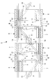
湾曲部5は、図2および図3に示されるように、円筒状の複数のコマ(節輪)6を長尺部2の中心軸に沿う方向に複数配列するとともに、隣接するコマ6どうしを相互にねじれの位置関係となる複数の揺動軸線A,B回りに揺動可能に連結して構成されている。
湾曲部5は、図2および図3に示されるように、円筒状の複数のコマ(節輪)6を長尺部2の中心軸に沿う方向に複数配列するとともに、隣接するコマ6どうしを相互にねじれの位置関係となる複数の揺動軸線A,B回りに揺動可能に連結して構成されている。
これにより、1つのコマ6は一方に隣接するコマ6に対して一方向に揺動する一方、他方に隣接するコマ6に対しては他の方向に揺動させられるので、連続する3以上のコマ6によってエンドエフェクタ3の姿勢を自由に変更可能な湾曲部5が構成されている。
各コマ6は、図4および図5に示されるように、円筒状の外壁部7と、該外壁部7の径方向内方に間隔をあけて同心に配置された円筒状の内壁部8と、これら外壁部7と内壁部8とを径方向に連結する連結部9とを備えている。
また、各コマ6の中心軸方向の両端には、隣接するコマ6どうしを揺動軸線A,Bによって連結するための一対の突起部10が中心軸を挟んで配置され、それぞれ中心軸に沿う方向に突出して設けられている。各コマ6の中心軸方向の両端の突起部10は、周方向の位相が90°異なっている。これにより、2つの揺動軸線A,Bは相互にねじれの位置関係となっている。
また、各コマ6の中心軸方向の両端には、隣接するコマ6どうしを揺動軸線A,Bによって連結するための一対の突起部10が中心軸を挟んで配置され、それぞれ中心軸に沿う方向に突出して設けられている。各コマ6の中心軸方向の両端の突起部10は、周方向の位相が90°異なっている。これにより、2つの揺動軸線A,Bは相互にねじれの位置関係となっている。
隣接する2つのコマ6の揺動軸線A,Bによって連結される突起部10は、図5に示されるように、径方向に重なって配置されるように径方向位置が相互に異なっている。
連結部9は、突起部10と同じ位相において、中心軸に沿う方向を板厚方向にして径方向に延びる帯板状の部分であって、板厚方向に貫通する貫通孔11を備えている。各コマ6の両端に配置される突起部10は位相が90°異なる位置に配置されているので、連結部9も位相を90°異ならせて配置されている。
図中、符号12は、張力によって湾曲部5を湾曲させるための4本のワイヤ14を貫通させる貫通孔である。
連結部9は、突起部10と同じ位相において、中心軸に沿う方向を板厚方向にして径方向に延びる帯板状の部分であって、板厚方向に貫通する貫通孔11を備えている。各コマ6の両端に配置される突起部10は位相が90°異なる位置に配置されているので、連結部9も位相を90°異ならせて配置されている。
図中、符号12は、張力によって湾曲部5を湾曲させるための4本のワイヤ14を貫通させる貫通孔である。
本実施形態においては、各コマ6の一の連結部9の貫通孔11を貫通したワイヤ13は、90°位相が異なる他の連結部9の貫通孔11を貫通するようになっている。隣接するコマ6の同一の揺動軸線A,Bによって連結される突起部10どうしは同じ位相に配置されるので、連結部9も同じ位相に配置される。したがって、ワイヤ13は、同じ位相に配置されている隣接するコマ6の2つの連結部9を貫通させられることで、これらの連結部9の間において揺動軸線A,Bに交差する位置を通過させられるようになっている。
また、ワイヤ13は、図5に示されるように、同一方向に位相がずれた位置に配置されている貫通孔11を順次貫通させられることにより、中心軸回りに一方向に旋回する螺旋状の形態をなして配置されている。
このように構成された本実施形態に係るマニピュレータ1の作用について以下に説明する。
本実施形態に係るマニピュレータ1は、中心軸方向に配列された複数のコマ6を、隣接するコマ6が相互にねじれの位置関係に配置される揺動軸線A,B回りに揺動可能となるように連結した湾曲部5を備えているので、湾曲部5の各揺動軸線A,B回りの揺動角度を調整することにより、長尺部2の先端に配置されているエンドエフェクタ3の姿勢を自由に変更することができる。
本実施形態に係るマニピュレータ1は、中心軸方向に配列された複数のコマ6を、隣接するコマ6が相互にねじれの位置関係に配置される揺動軸線A,B回りに揺動可能となるように連結した湾曲部5を備えているので、湾曲部5の各揺動軸線A,B回りの揺動角度を調整することにより、長尺部2の先端に配置されているエンドエフェクタ3の姿勢を自由に変更することができる。
そして、駆動部4の作動によりワイヤ13に張力を付与すると、張力がワイヤ13によってエンドエフェクタ3に伝達されて、エンドエフェクタ3が作動させられる。
この場合において、ワイヤ13は、各揺動軸線A,Bに交差する位置を通過させられているので、いずれの揺動軸線A,B回りに隣接するコマ6が相対的に揺動させられても、ワイヤ13は図6に示されるように曲げられることで揺動による変位を吸収する。
この場合において、ワイヤ13は、各揺動軸線A,Bに交差する位置を通過させられているので、いずれの揺動軸線A,B回りに隣接するコマ6が相対的に揺動させられても、ワイヤ13は図6に示されるように曲げられることで揺動による変位を吸収する。
すなわち、湾曲部5が湾曲させられることによるワイヤ13の可動部は、各揺動軸線A,Bの近傍のみに配置され、ワイヤ13の他の部分は変位しない。このため、全ての揺動軸線A,B回りにコマ6が相対的に揺動させられても、ワイヤ13には曲げ力が作用するのみで、張力または圧縮力が作用することはなく、複数本のワイヤ13に経路長差が発生することを効果的に防止することができる。
すなわち、湾曲部5の各コマ6を各揺動軸線A,B回りに揺動させることでエンドエフェクタ3の姿勢を変更しても、エンドエフェクタ3を駆動するためのワイヤ13に余計な張力が作用しないので、エンドエフェクタ3が意図せず動作させられてしまうことがなく、操作性を向上することができるという利点がある。
また、本実施形態においては、駆動部4として、モータにより駆動されるものを採用してもよいし、手動操作によって駆動されるものを採用してもよい。
また、本実施形態においては、二重管状に形成された外壁部7と内壁部8との間の円筒状の隙間に沿ってエンドエフェクタ3を駆動するためのワイヤ13を配置しているので、内壁部8の内側については、中心軸近傍の連続する空間を確保することができ、エンドエフェクタ3への配線や配管を、ワイヤ13に邪魔されることなく通すために有効に利用することができる。
また、本実施形態においては、二重管状に形成された外壁部7と内壁部8との間の円筒状の隙間に沿ってエンドエフェクタ3を駆動するためのワイヤ13を配置しているので、内壁部8の内側については、中心軸近傍の連続する空間を確保することができ、エンドエフェクタ3への配線や配管を、ワイヤ13に邪魔されることなく通すために有効に利用することができる。
なお、本実施形態においては、各コマ6の中心軸に沿う方向の両端に配置されている揺動軸線A,Bの位相が90°ずれている場合を例示したが、これに限定されるものではなく、位相の大きさは任意でよい。
また、連結部9においてワイヤ13を貫通させる貫通孔11が、中心軸に平行に延びている場合を例示したが、これに代えて、図7に示されるように、周方向一方向に傾斜する方向に貫通していてもよい。ワイヤ13が揺動軸線A,Bに交差する位置を通過しさえすれば、経路長差が発生しない作用は同様であり、ワイヤ13を斜めに通過させることで、螺旋状に配置されるワイヤ13を無理なく配置することができるという利点がある。
1 マニピュレータ
2 長尺部
3 エンドエフェクタ
4 駆動部
5 湾曲部
6 コマ
7 外壁部
8 内壁部
9 連結部
11 貫通孔
13 ワイヤ
A,B 揺動軸線
2 長尺部
3 エンドエフェクタ
4 駆動部
5 湾曲部
6 コマ
7 外壁部
8 内壁部
9 連結部
11 貫通孔
13 ワイヤ
A,B 揺動軸線
Claims (4)
- 細長い長尺部と、
該長尺部の先端に配置されるエンドエフェクタと、
前記長尺部の基端に配置される駆動部と、
該駆動部において発生した動力を前記エンドエフェクタに伝達する1以上のワイヤとを備え、
前記長尺部が、該長尺部の中心軸に沿う方向に配列された複数のコマを、両方向に隣接する前記コマが相互にねじれの位置関係に配置される揺動軸線回りに揺動可能となるように連結してなる湾曲部を備え、
前記ワイヤが、前記中心軸から径方向に離れた位置で各前記揺動軸線に交差する位置を通過するように配置されているマニピュレータ。 - 各前記コマが、円筒状の外壁部と、該外壁部の径方向内方において、各前記揺動軸線に交差する位置を前記中心軸に沿う方向に延び、前記ワイヤを貫通させる貫通孔とを備える請求項1に記載のマニピュレータ。
- 前記ワイヤが、前記中心軸に沿う方向に、前記中心軸回りの周方向の同一方向に隣接する位置に配置されている前記貫通孔を順次貫通して、螺旋状に配置されている請求項2に記載のマニピュレータ。
- 各前記コマが、前記外壁部の径方向内方に間隔をあけて同心に配置された円筒状の内壁部と、該内壁部と前記外壁部とを前記揺動軸線近傍において連結する平板状の連結部とを備え、
該連結部に前記貫通孔が設けられている請求項2または請求項3に記載のマニピュレータ。
Priority Applications (2)
| Application Number | Priority Date | Filing Date | Title |
|---|---|---|---|
| PCT/JP2017/021932 WO2018229889A1 (ja) | 2017-06-14 | 2017-06-14 | マニピュレータ |
| US16/710,088 US11203114B2 (en) | 2017-06-14 | 2019-12-11 | Manipulator |
Applications Claiming Priority (1)
| Application Number | Priority Date | Filing Date | Title |
|---|---|---|---|
| PCT/JP2017/021932 WO2018229889A1 (ja) | 2017-06-14 | 2017-06-14 | マニピュレータ |
Related Child Applications (1)
| Application Number | Title | Priority Date | Filing Date |
|---|---|---|---|
| US16/710,088 Continuation US11203114B2 (en) | 2017-06-14 | 2019-12-11 | Manipulator |
Publications (1)
| Publication Number | Publication Date |
|---|---|
| WO2018229889A1 true WO2018229889A1 (ja) | 2018-12-20 |
Family
ID=64659162
Family Applications (1)
| Application Number | Title | Priority Date | Filing Date |
|---|---|---|---|
| PCT/JP2017/021932 Ceased WO2018229889A1 (ja) | 2017-06-14 | 2017-06-14 | マニピュレータ |
Country Status (2)
| Country | Link |
|---|---|
| US (1) | US11203114B2 (ja) |
| WO (1) | WO2018229889A1 (ja) |
Cited By (5)
| Publication number | Priority date | Publication date | Assignee | Title |
|---|---|---|---|---|
| CN111941404A (zh) * | 2020-08-25 | 2020-11-17 | 长沙理工大学 | 一种机器人系统的工作方法 |
| CN111941406A (zh) * | 2020-08-25 | 2020-11-17 | 长沙理工大学 | 一种机器人系统 |
| CN111941410A (zh) * | 2020-08-25 | 2020-11-17 | 长沙理工大学 | 一种避免松弛式丝驱动机器人 |
| CN111941405A (zh) * | 2020-08-25 | 2020-11-17 | 长沙理工大学 | 一种丝驱动蛇形臂机器人 |
| CN113100949A (zh) * | 2021-04-16 | 2021-07-13 | 天津大学医疗机器人与智能系统研究院 | 手术机器人用前端执行装置 |
Families Citing this family (187)
| Publication number | Priority date | Publication date | Assignee | Title |
|---|---|---|---|---|
| US20070084897A1 (en) | 2003-05-20 | 2007-04-19 | Shelton Frederick E Iv | Articulating surgical stapling instrument incorporating a two-piece e-beam firing mechanism |
| US9060770B2 (en) | 2003-05-20 | 2015-06-23 | Ethicon Endo-Surgery, Inc. | Robotically-driven surgical instrument with E-beam driver |
| US9072535B2 (en) | 2011-05-27 | 2015-07-07 | Ethicon Endo-Surgery, Inc. | Surgical stapling instruments with rotatable staple deployment arrangements |
| US11890012B2 (en) | 2004-07-28 | 2024-02-06 | Cilag Gmbh International | Staple cartridge comprising cartridge body and attached support |
| US11998198B2 (en) | 2004-07-28 | 2024-06-04 | Cilag Gmbh International | Surgical stapling instrument incorporating a two-piece E-beam firing mechanism |
| US7669746B2 (en) | 2005-08-31 | 2010-03-02 | Ethicon Endo-Surgery, Inc. | Staple cartridges for forming staples having differing formed staple heights |
| US10159482B2 (en) | 2005-08-31 | 2018-12-25 | Ethicon Llc | Fastener cartridge assembly comprising a fixed anvil and different staple heights |
| US11246590B2 (en) | 2005-08-31 | 2022-02-15 | Cilag Gmbh International | Staple cartridge including staple drivers having different unfired heights |
| US8708213B2 (en) | 2006-01-31 | 2014-04-29 | Ethicon Endo-Surgery, Inc. | Surgical instrument having a feedback system |
| US11793518B2 (en) | 2006-01-31 | 2023-10-24 | Cilag Gmbh International | Powered surgical instruments with firing system lockout arrangements |
| US20120292367A1 (en) | 2006-01-31 | 2012-11-22 | Ethicon Endo-Surgery, Inc. | Robotically-controlled end effector |
| US8186555B2 (en) | 2006-01-31 | 2012-05-29 | Ethicon Endo-Surgery, Inc. | Motor-driven surgical cutting and fastening instrument with mechanical closure system |
| US7845537B2 (en) | 2006-01-31 | 2010-12-07 | Ethicon Endo-Surgery, Inc. | Surgical instrument having recording capabilities |
| US8992422B2 (en) | 2006-03-23 | 2015-03-31 | Ethicon Endo-Surgery, Inc. | Robotically-controlled endoscopic accessory channel |
| US10568652B2 (en) | 2006-09-29 | 2020-02-25 | Ethicon Llc | Surgical staples having attached drivers of different heights and stapling instruments for deploying the same |
| US11980366B2 (en) | 2006-10-03 | 2024-05-14 | Cilag Gmbh International | Surgical instrument |
| US8632535B2 (en) | 2007-01-10 | 2014-01-21 | Ethicon Endo-Surgery, Inc. | Interlock and surgical instrument including same |
| US8684253B2 (en) | 2007-01-10 | 2014-04-01 | Ethicon Endo-Surgery, Inc. | Surgical instrument with wireless communication between a control unit of a robotic system and remote sensor |
| US20080169332A1 (en) | 2007-01-11 | 2008-07-17 | Shelton Frederick E | Surgical stapling device with a curved cutting member |
| US8931682B2 (en) | 2007-06-04 | 2015-01-13 | Ethicon Endo-Surgery, Inc. | Robotically-controlled shaft based rotary drive systems for surgical instruments |
| US11857181B2 (en) | 2007-06-04 | 2024-01-02 | Cilag Gmbh International | Robotically-controlled shaft based rotary drive systems for surgical instruments |
| US11849941B2 (en) | 2007-06-29 | 2023-12-26 | Cilag Gmbh International | Staple cartridge having staple cavities extending at a transverse angle relative to a longitudinal cartridge axis |
| RU2493788C2 (ru) | 2008-02-14 | 2013-09-27 | Этикон Эндо-Серджери, Инк. | Хирургический режущий и крепежный инструмент, имеющий радиочастотные электроды |
| US8636736B2 (en) | 2008-02-14 | 2014-01-28 | Ethicon Endo-Surgery, Inc. | Motorized surgical cutting and fastening instrument |
| US8573465B2 (en) | 2008-02-14 | 2013-11-05 | Ethicon Endo-Surgery, Inc. | Robotically-controlled surgical end effector system with rotary actuated closure systems |
| US11986183B2 (en) | 2008-02-14 | 2024-05-21 | Cilag Gmbh International | Surgical cutting and fastening instrument comprising a plurality of sensors to measure an electrical parameter |
| US20130153641A1 (en) | 2008-02-15 | 2013-06-20 | Ethicon Endo-Surgery, Inc. | Releasable layer of material and surgical end effector having the same |
| US11648005B2 (en) | 2008-09-23 | 2023-05-16 | Cilag Gmbh International | Robotically-controlled motorized surgical instrument with an end effector |
| US9386983B2 (en) | 2008-09-23 | 2016-07-12 | Ethicon Endo-Surgery, Llc | Robotically-controlled motorized surgical instrument |
| US9005230B2 (en) | 2008-09-23 | 2015-04-14 | Ethicon Endo-Surgery, Inc. | Motorized surgical instrument |
| US8210411B2 (en) | 2008-09-23 | 2012-07-03 | Ethicon Endo-Surgery, Inc. | Motor-driven surgical cutting instrument |
| US8608045B2 (en) | 2008-10-10 | 2013-12-17 | Ethicon Endo-Sugery, Inc. | Powered surgical cutting and stapling apparatus with manually retractable firing system |
| US8220688B2 (en) | 2009-12-24 | 2012-07-17 | Ethicon Endo-Surgery, Inc. | Motor-driven surgical cutting instrument with electric actuator directional control assembly |
| US11812965B2 (en) | 2010-09-30 | 2023-11-14 | Cilag Gmbh International | Layer of material for a surgical end effector |
| US9629814B2 (en) | 2010-09-30 | 2017-04-25 | Ethicon Endo-Surgery, Llc | Tissue thickness compensator configured to redistribute compressive forces |
| US9320523B2 (en) | 2012-03-28 | 2016-04-26 | Ethicon Endo-Surgery, Llc | Tissue thickness compensator comprising tissue ingrowth features |
| US10405854B2 (en) | 2010-09-30 | 2019-09-10 | Ethicon Llc | Surgical stapling cartridge with layer retention features |
| US12213666B2 (en) | 2010-09-30 | 2025-02-04 | Cilag Gmbh International | Tissue thickness compensator comprising layers |
| US10945731B2 (en) | 2010-09-30 | 2021-03-16 | Ethicon Llc | Tissue thickness compensator comprising controlled release and expansion |
| US11925354B2 (en) | 2010-09-30 | 2024-03-12 | Cilag Gmbh International | Staple cartridge comprising staples positioned within a compressible portion thereof |
| US8695866B2 (en) | 2010-10-01 | 2014-04-15 | Ethicon Endo-Surgery, Inc. | Surgical instrument having a power control circuit |
| BR112013027794B1 (pt) | 2011-04-29 | 2020-12-15 | Ethicon Endo-Surgery, Inc | Conjunto de cartucho de grampos |
| US11207064B2 (en) | 2011-05-27 | 2021-12-28 | Cilag Gmbh International | Automated end effector component reloading system for use with a robotic system |
| MX350846B (es) | 2012-03-28 | 2017-09-22 | Ethicon Endo Surgery Inc | Compensador de grosor de tejido que comprende cápsulas que definen un ambiente de baja presión. |
| MX358135B (es) | 2012-03-28 | 2018-08-06 | Ethicon Endo Surgery Inc | Compensador de grosor de tejido que comprende una pluralidad de capas. |
| US9101358B2 (en) | 2012-06-15 | 2015-08-11 | Ethicon Endo-Surgery, Inc. | Articulatable surgical instrument comprising a firing drive |
| US20140001231A1 (en) | 2012-06-28 | 2014-01-02 | Ethicon Endo-Surgery, Inc. | Firing system lockout arrangements for surgical instruments |
| US9289256B2 (en) | 2012-06-28 | 2016-03-22 | Ethicon Endo-Surgery, Llc | Surgical end effectors having angled tissue-contacting surfaces |
| US12383267B2 (en) | 2012-06-28 | 2025-08-12 | Cilag Gmbh International | Robotically powered surgical device with manually-actuatable reversing system |
| MX368026B (es) | 2013-03-01 | 2019-09-12 | Ethicon Endo Surgery Inc | Instrumento quirúrgico articulable con vías conductoras para la comunicación de la señal. |
| RU2669463C2 (ru) | 2013-03-01 | 2018-10-11 | Этикон Эндо-Серджери, Инк. | Хирургический инструмент с мягким упором |
| US9629629B2 (en) | 2013-03-14 | 2017-04-25 | Ethicon Endo-Surgey, LLC | Control systems for surgical instruments |
| BR112015026109B1 (pt) | 2013-04-16 | 2022-02-22 | Ethicon Endo-Surgery, Inc | Instrumento cirúrgico |
| US20150053737A1 (en) | 2013-08-23 | 2015-02-26 | Ethicon Endo-Surgery, Inc. | End effector detection systems for surgical instruments |
| US12232723B2 (en) | 2014-03-26 | 2025-02-25 | Cilag Gmbh International | Systems and methods for controlling a segmented circuit |
| US9750499B2 (en) | 2014-03-26 | 2017-09-05 | Ethicon Llc | Surgical stapling instrument system |
| US10013049B2 (en) | 2014-03-26 | 2018-07-03 | Ethicon Llc | Power management through sleep options of segmented circuit and wake up control |
| US20150297223A1 (en) | 2014-04-16 | 2015-10-22 | Ethicon Endo-Surgery, Inc. | Fastener cartridges including extensions having different configurations |
| US10327764B2 (en) | 2014-09-26 | 2019-06-25 | Ethicon Llc | Method for creating a flexible staple line |
| JP6532889B2 (ja) | 2014-04-16 | 2019-06-19 | エシコン エルエルシーEthicon LLC | 締結具カートリッジ組立体及びステープル保持具カバー配置構成 |
| CN106456176B (zh) | 2014-04-16 | 2019-06-28 | 伊西康内外科有限责任公司 | 包括具有不同构型的延伸部的紧固件仓 |
| CN106456158B (zh) | 2014-04-16 | 2019-02-05 | 伊西康内外科有限责任公司 | 包括非一致紧固件的紧固件仓 |
| US11311294B2 (en) | 2014-09-05 | 2022-04-26 | Cilag Gmbh International | Powered medical device including measurement of closure state of jaws |
| US9724094B2 (en) | 2014-09-05 | 2017-08-08 | Ethicon Llc | Adjunct with integrated sensors to quantify tissue compression |
| BR112017004361B1 (pt) | 2014-09-05 | 2023-04-11 | Ethicon Llc | Sistema eletrônico para um instrumento cirúrgico |
| US10105142B2 (en) | 2014-09-18 | 2018-10-23 | Ethicon Llc | Surgical stapler with plurality of cutting elements |
| US11523821B2 (en) | 2014-09-26 | 2022-12-13 | Cilag Gmbh International | Method for creating a flexible staple line |
| US9924944B2 (en) | 2014-10-16 | 2018-03-27 | Ethicon Llc | Staple cartridge comprising an adjunct material |
| US10517594B2 (en) | 2014-10-29 | 2019-12-31 | Ethicon Llc | Cartridge assemblies for surgical staplers |
| US10736636B2 (en) | 2014-12-10 | 2020-08-11 | Ethicon Llc | Articulatable surgical instrument system |
| US9987000B2 (en) | 2014-12-18 | 2018-06-05 | Ethicon Llc | Surgical instrument assembly comprising a flexible articulation system |
| RU2703684C2 (ru) | 2014-12-18 | 2019-10-21 | ЭТИКОН ЭНДО-СЕРДЖЕРИ, ЭлЭлСи | Хирургический инструмент с упором, который выполнен с возможностью избирательного перемещения относительно кассеты со скобами вокруг дискретной неподвижной оси |
| US10085748B2 (en) | 2014-12-18 | 2018-10-02 | Ethicon Llc | Locking arrangements for detachable shaft assemblies with articulatable surgical end effectors |
| US11154301B2 (en) | 2015-02-27 | 2021-10-26 | Cilag Gmbh International | Modular stapling assembly |
| US9808246B2 (en) | 2015-03-06 | 2017-11-07 | Ethicon Endo-Surgery, Llc | Method of operating a powered surgical instrument |
| US10441279B2 (en) | 2015-03-06 | 2019-10-15 | Ethicon Llc | Multiple level thresholds to modify operation of powered surgical instruments |
| US10390825B2 (en) | 2015-03-31 | 2019-08-27 | Ethicon Llc | Surgical instrument with progressive rotary drive systems |
| US10105139B2 (en) | 2015-09-23 | 2018-10-23 | Ethicon Llc | Surgical stapler having downstream current-based motor control |
| US10299878B2 (en) | 2015-09-25 | 2019-05-28 | Ethicon Llc | Implantable adjunct systems for determining adjunct skew |
| US10172620B2 (en) | 2015-09-30 | 2019-01-08 | Ethicon Llc | Compressible adjuncts with bonding nodes |
| US11890015B2 (en) | 2015-09-30 | 2024-02-06 | Cilag Gmbh International | Compressible adjunct with crossing spacer fibers |
| US10736633B2 (en) | 2015-09-30 | 2020-08-11 | Ethicon Llc | Compressible adjunct with looping members |
| US10265068B2 (en) | 2015-12-30 | 2019-04-23 | Ethicon Llc | Surgical instruments with separable motors and motor control circuits |
| US10292704B2 (en) | 2015-12-30 | 2019-05-21 | Ethicon Llc | Mechanisms for compensating for battery pack failure in powered surgical instruments |
| US11213293B2 (en) | 2016-02-09 | 2022-01-04 | Cilag Gmbh International | Articulatable surgical instruments with single articulation link arrangements |
| US10448948B2 (en) | 2016-02-12 | 2019-10-22 | Ethicon Llc | Mechanisms for compensating for drivetrain failure in powered surgical instruments |
| US10828028B2 (en) | 2016-04-15 | 2020-11-10 | Ethicon Llc | Surgical instrument with multiple program responses during a firing motion |
| US10357247B2 (en) | 2016-04-15 | 2019-07-23 | Ethicon Llc | Surgical instrument with multiple program responses during a firing motion |
| US20170296173A1 (en) | 2016-04-18 | 2017-10-19 | Ethicon Endo-Surgery, Llc | Method for operating a surgical instrument |
| US10500000B2 (en) | 2016-08-16 | 2019-12-10 | Ethicon Llc | Surgical tool with manual control of end effector jaws |
| JP7010956B2 (ja) | 2016-12-21 | 2022-01-26 | エシコン エルエルシー | 組織をステープル留めする方法 |
| US10568626B2 (en) | 2016-12-21 | 2020-02-25 | Ethicon Llc | Surgical instruments with jaw opening features for increasing a jaw opening distance |
| US10639035B2 (en) | 2016-12-21 | 2020-05-05 | Ethicon Llc | Surgical stapling instruments and replaceable tool assemblies thereof |
| US10758230B2 (en) | 2016-12-21 | 2020-09-01 | Ethicon Llc | Surgical instrument with primary and safety processors |
| US11090048B2 (en) | 2016-12-21 | 2021-08-17 | Cilag Gmbh International | Method for resetting a fuse of a surgical instrument shaft |
| JP7010957B2 (ja) | 2016-12-21 | 2022-01-26 | エシコン エルエルシー | ロックアウトを備えるシャフトアセンブリ |
| US10779820B2 (en) | 2017-06-20 | 2020-09-22 | Ethicon Llc | Systems and methods for controlling motor speed according to user input for a surgical instrument |
| US10307170B2 (en) | 2017-06-20 | 2019-06-04 | Ethicon Llc | Method for closed loop control of motor velocity of a surgical stapling and cutting instrument |
| US10881399B2 (en) | 2017-06-20 | 2021-01-05 | Ethicon Llc | Techniques for adaptive control of motor velocity of a surgical stapling and cutting instrument |
| US11000279B2 (en) | 2017-06-28 | 2021-05-11 | Ethicon Llc | Surgical instrument comprising an articulation system ratio |
| BR112019027065B1 (pt) | 2017-06-28 | 2023-12-26 | Ethicon Llc | Instrumento cirúrgico e sistema cirúrgico |
| USD906355S1 (en) | 2017-06-28 | 2020-12-29 | Ethicon Llc | Display screen or portion thereof with a graphical user interface for a surgical instrument |
| US10765427B2 (en) | 2017-06-28 | 2020-09-08 | Ethicon Llc | Method for articulating a surgical instrument |
| EP4070740B1 (en) | 2017-06-28 | 2025-03-26 | Cilag GmbH International | Surgical instrument comprising selectively actuatable rotatable couplers |
| US10932772B2 (en) | 2017-06-29 | 2021-03-02 | Ethicon Llc | Methods for closed loop velocity control for robotic surgical instrument |
| US11944300B2 (en) | 2017-08-03 | 2024-04-02 | Cilag Gmbh International | Method for operating a surgical system bailout |
| US11974742B2 (en) | 2017-08-03 | 2024-05-07 | Cilag Gmbh International | Surgical system comprising an articulation bailout |
| US11134944B2 (en) | 2017-10-30 | 2021-10-05 | Cilag Gmbh International | Surgical stapler knife motion controls |
| US10842490B2 (en) | 2017-10-31 | 2020-11-24 | Ethicon Llc | Cartridge body design with force reduction based on firing completion |
| US10779826B2 (en) | 2017-12-15 | 2020-09-22 | Ethicon Llc | Methods of operating surgical end effectors |
| US10835330B2 (en) | 2017-12-19 | 2020-11-17 | Ethicon Llc | Method for determining the position of a rotatable jaw of a surgical instrument attachment assembly |
| US12336705B2 (en) | 2017-12-21 | 2025-06-24 | Cilag Gmbh International | Continuous use self-propelled stapling instrument |
| US11751867B2 (en) | 2017-12-21 | 2023-09-12 | Cilag Gmbh International | Surgical instrument comprising sequenced systems |
| WO2019136041A1 (en) * | 2018-01-04 | 2019-07-11 | Covidien Lp | Robotic surgical instrument including high articulation wrist assembly with torque transmission and mechanical manipulation |
| US11458641B2 (en) * | 2018-05-23 | 2022-10-04 | General Electric Company | Robotic arm assembly construction |
| US20200054321A1 (en) | 2018-08-20 | 2020-02-20 | Ethicon Llc | Surgical instruments with progressive jaw closure arrangements |
| US11207065B2 (en) | 2018-08-20 | 2021-12-28 | Cilag Gmbh International | Method for fabricating surgical stapler anvils |
| US11291440B2 (en) | 2018-08-20 | 2022-04-05 | Cilag Gmbh International | Method for operating a powered articulatable surgical instrument |
| US11696761B2 (en) | 2019-03-25 | 2023-07-11 | Cilag Gmbh International | Firing drive arrangements for surgical systems |
| US20200345359A1 (en) | 2019-04-30 | 2020-11-05 | Ethicon Llc | Tissue stop for a surgical instrument |
| US11903581B2 (en) | 2019-04-30 | 2024-02-20 | Cilag Gmbh International | Methods for stapling tissue using a surgical instrument |
| US11241235B2 (en) | 2019-06-28 | 2022-02-08 | Cilag Gmbh International | Method of using multiple RFID chips with a surgical assembly |
| US12004740B2 (en) | 2019-06-28 | 2024-06-11 | Cilag Gmbh International | Surgical stapling system having an information decryption protocol |
| US11684434B2 (en) | 2019-06-28 | 2023-06-27 | Cilag Gmbh International | Surgical RFID assemblies for instrument operational setting control |
| US11660163B2 (en) | 2019-06-28 | 2023-05-30 | Cilag Gmbh International | Surgical system with RFID tags for updating motor assembly parameters |
| US11771419B2 (en) | 2019-06-28 | 2023-10-03 | Cilag Gmbh International | Packaging for a replaceable component of a surgical stapling system |
| US12405187B2 (en) | 2019-10-04 | 2025-09-02 | General Electric Company | Insertion apparatus for use with rotary machines |
| US12035913B2 (en) | 2019-12-19 | 2024-07-16 | Cilag Gmbh International | Staple cartridge comprising a deployable knife |
| US11844520B2 (en) | 2019-12-19 | 2023-12-19 | Cilag Gmbh International | Staple cartridge comprising driver retention members |
| US11701111B2 (en) | 2019-12-19 | 2023-07-18 | Cilag Gmbh International | Method for operating a surgical stapling instrument |
| US12091981B2 (en) | 2020-06-11 | 2024-09-17 | General Electric Company | Insertion tool and method |
| US11638582B2 (en) | 2020-07-28 | 2023-05-02 | Cilag Gmbh International | Surgical instruments with torsion spine drive arrangements |
| USD1013170S1 (en) | 2020-10-29 | 2024-01-30 | Cilag Gmbh International | Surgical instrument assembly |
| US11896217B2 (en) | 2020-10-29 | 2024-02-13 | Cilag Gmbh International | Surgical instrument comprising an articulation lock |
| US11779330B2 (en) | 2020-10-29 | 2023-10-10 | Cilag Gmbh International | Surgical instrument comprising a jaw alignment system |
| US12053175B2 (en) | 2020-10-29 | 2024-08-06 | Cilag Gmbh International | Surgical instrument comprising a stowed closure actuator stop |
| US11931025B2 (en) | 2020-10-29 | 2024-03-19 | Cilag Gmbh International | Surgical instrument comprising a releasable closure drive lock |
| US11844518B2 (en) | 2020-10-29 | 2023-12-19 | Cilag Gmbh International | Method for operating a surgical instrument |
| US11737751B2 (en) | 2020-12-02 | 2023-08-29 | Cilag Gmbh International | Devices and methods of managing energy dissipated within sterile barriers of surgical instrument housings |
| US11890010B2 (en) | 2020-12-02 | 2024-02-06 | Cllag GmbH International | Dual-sided reinforced reload for surgical instruments |
| US11744581B2 (en) | 2020-12-02 | 2023-09-05 | Cilag Gmbh International | Powered surgical instruments with multi-phase tissue treatment |
| US11653915B2 (en) | 2020-12-02 | 2023-05-23 | Cilag Gmbh International | Surgical instruments with sled location detection and adjustment features |
| US11653920B2 (en) | 2020-12-02 | 2023-05-23 | Cilag Gmbh International | Powered surgical instruments with communication interfaces through sterile barrier |
| US11944296B2 (en) | 2020-12-02 | 2024-04-02 | Cilag Gmbh International | Powered surgical instruments with external connectors |
| US11849943B2 (en) | 2020-12-02 | 2023-12-26 | Cilag Gmbh International | Surgical instrument with cartridge release mechanisms |
| US12471982B2 (en) | 2020-12-02 | 2025-11-18 | Cilag Gmbh International | Method for tissue treatment by surgical instrument |
| US12504616B2 (en) | 2021-01-08 | 2025-12-23 | General Electric Company | Insertion tool |
| US12416800B2 (en) * | 2021-01-08 | 2025-09-16 | General Electric Company | Insertion tool |
| US11749877B2 (en) | 2021-02-26 | 2023-09-05 | Cilag Gmbh International | Stapling instrument comprising a signal antenna |
| US12324580B2 (en) | 2021-02-26 | 2025-06-10 | Cilag Gmbh International | Method of powering and communicating with a staple cartridge |
| US11925349B2 (en) | 2021-02-26 | 2024-03-12 | Cilag Gmbh International | Adjustment to transfer parameters to improve available power |
| US11812964B2 (en) | 2021-02-26 | 2023-11-14 | Cilag Gmbh International | Staple cartridge comprising a power management circuit |
| US11701113B2 (en) | 2021-02-26 | 2023-07-18 | Cilag Gmbh International | Stapling instrument comprising a separate power antenna and a data transfer antenna |
| US11751869B2 (en) | 2021-02-26 | 2023-09-12 | Cilag Gmbh International | Monitoring of multiple sensors over time to detect moving characteristics of tissue |
| US12108951B2 (en) | 2021-02-26 | 2024-10-08 | Cilag Gmbh International | Staple cartridge comprising a sensing array and a temperature control system |
| US11980362B2 (en) | 2021-02-26 | 2024-05-14 | Cilag Gmbh International | Surgical instrument system comprising a power transfer coil |
| US11744583B2 (en) | 2021-02-26 | 2023-09-05 | Cilag Gmbh International | Distal communication array to tune frequency of RF systems |
| US11723657B2 (en) | 2021-02-26 | 2023-08-15 | Cilag Gmbh International | Adjustable communication based on available bandwidth and power capacity |
| US11793514B2 (en) | 2021-02-26 | 2023-10-24 | Cilag Gmbh International | Staple cartridge comprising sensor array which may be embedded in cartridge body |
| US11696757B2 (en) | 2021-02-26 | 2023-07-11 | Cilag Gmbh International | Monitoring of internal systems to detect and track cartridge motion status |
| US11950777B2 (en) | 2021-02-26 | 2024-04-09 | Cilag Gmbh International | Staple cartridge comprising an information access control system |
| US11730473B2 (en) | 2021-02-26 | 2023-08-22 | Cilag Gmbh International | Monitoring of manufacturing life-cycle |
| US11717291B2 (en) | 2021-03-22 | 2023-08-08 | Cilag Gmbh International | Staple cartridge comprising staples configured to apply different tissue compression |
| US11737749B2 (en) | 2021-03-22 | 2023-08-29 | Cilag Gmbh International | Surgical stapling instrument comprising a retraction system |
| US11723658B2 (en) | 2021-03-22 | 2023-08-15 | Cilag Gmbh International | Staple cartridge comprising a firing lockout |
| US11826042B2 (en) | 2021-03-22 | 2023-11-28 | Cilag Gmbh International | Surgical instrument comprising a firing drive including a selectable leverage mechanism |
| US11806011B2 (en) | 2021-03-22 | 2023-11-07 | Cilag Gmbh International | Stapling instrument comprising tissue compression systems |
| US11826012B2 (en) | 2021-03-22 | 2023-11-28 | Cilag Gmbh International | Stapling instrument comprising a pulsed motor-driven firing rack |
| US11759202B2 (en) | 2021-03-22 | 2023-09-19 | Cilag Gmbh International | Staple cartridge comprising an implantable layer |
| US11793516B2 (en) | 2021-03-24 | 2023-10-24 | Cilag Gmbh International | Surgical staple cartridge comprising longitudinal support beam |
| US11786243B2 (en) | 2021-03-24 | 2023-10-17 | Cilag Gmbh International | Firing members having flexible portions for adapting to a load during a surgical firing stroke |
| US11786239B2 (en) | 2021-03-24 | 2023-10-17 | Cilag Gmbh International | Surgical instrument articulation joint arrangements comprising multiple moving linkage features |
| US11896219B2 (en) | 2021-03-24 | 2024-02-13 | Cilag Gmbh International | Mating features between drivers and underside of a cartridge deck |
| US11744603B2 (en) * | 2021-03-24 | 2023-09-05 | Cilag Gmbh International | Multi-axis pivot joints for surgical instruments and methods for manufacturing same |
| US11832816B2 (en) | 2021-03-24 | 2023-12-05 | Cilag Gmbh International | Surgical stapling assembly comprising nonplanar staples and planar staples |
| US11849945B2 (en) | 2021-03-24 | 2023-12-26 | Cilag Gmbh International | Rotary-driven surgical stapling assembly comprising eccentrically driven firing member |
| US11896218B2 (en) | 2021-03-24 | 2024-02-13 | Cilag Gmbh International | Method of using a powered stapling device |
| US12102323B2 (en) | 2021-03-24 | 2024-10-01 | Cilag Gmbh International | Rotary-driven surgical stapling assembly comprising a floatable component |
| US11944336B2 (en) * | 2021-03-24 | 2024-04-02 | Cilag Gmbh International | Joint arrangements for multi-planar alignment and support of operational drive shafts in articulatable surgical instruments |
| US11903582B2 (en) | 2021-03-24 | 2024-02-20 | Cilag Gmbh International | Leveraging surfaces for cartridge installation |
| US11857183B2 (en) | 2021-03-24 | 2024-01-02 | Cilag Gmbh International | Stapling assembly components having metal substrates and plastic bodies |
| US11849944B2 (en) | 2021-03-24 | 2023-12-26 | Cilag Gmbh International | Drivers for fastener cartridge assemblies having rotary drive screws |
| US20220378425A1 (en) | 2021-05-28 | 2022-12-01 | Cilag Gmbh International | Stapling instrument comprising a control system that controls a firing stroke length |
| US11980363B2 (en) | 2021-10-18 | 2024-05-14 | Cilag Gmbh International | Row-to-row staple array variations |
| US11937816B2 (en) | 2021-10-28 | 2024-03-26 | Cilag Gmbh International | Electrical lead arrangements for surgical instruments |
| US12432790B2 (en) | 2021-10-28 | 2025-09-30 | Cilag Gmbh International | Method and device for transmitting UART communications over a security short range wireless communication |
| US12089841B2 (en) | 2021-10-28 | 2024-09-17 | Cilag CmbH International | Staple cartridge identification systems |
Citations (2)
| Publication number | Priority date | Publication date | Assignee | Title |
|---|---|---|---|---|
| WO2015093602A1 (ja) * | 2013-12-20 | 2015-06-25 | オリンパス株式会社 | 軟性マニピュレータ用ガイド部材および軟性マニピュレータ |
| JP2017512659A (ja) * | 2014-02-21 | 2017-05-25 | インテュイティブ サージカル オペレーションズ, インコーポレイテッド | 運動が拘束される関節運動可能部材、並びに関連する装置及び方法 |
Family Cites Families (5)
| Publication number | Priority date | Publication date | Assignee | Title |
|---|---|---|---|---|
| US20030135204A1 (en) * | 2001-02-15 | 2003-07-17 | Endo Via Medical, Inc. | Robotically controlled medical instrument with a flexible section |
| US7699835B2 (en) * | 2001-02-15 | 2010-04-20 | Hansen Medical, Inc. | Robotically controlled surgical instruments |
| JP2010017483A (ja) | 2008-07-14 | 2010-01-28 | Olympus Corp | 内視鏡湾曲管及び湾曲管を有する内視鏡 |
| JP2010259479A (ja) | 2009-04-30 | 2010-11-18 | Hoya Corp | 内視鏡用処置具 |
| US9339341B2 (en) | 2010-02-08 | 2016-05-17 | Intuitive Surgical Operations, Inc. | Direct pull surgical gripper |
-
2017
- 2017-06-14 WO PCT/JP2017/021932 patent/WO2018229889A1/ja not_active Ceased
-
2019
- 2019-12-11 US US16/710,088 patent/US11203114B2/en active Active
Patent Citations (2)
| Publication number | Priority date | Publication date | Assignee | Title |
|---|---|---|---|---|
| WO2015093602A1 (ja) * | 2013-12-20 | 2015-06-25 | オリンパス株式会社 | 軟性マニピュレータ用ガイド部材および軟性マニピュレータ |
| JP2017512659A (ja) * | 2014-02-21 | 2017-05-25 | インテュイティブ サージカル オペレーションズ, インコーポレイテッド | 運動が拘束される関節運動可能部材、並びに関連する装置及び方法 |
Cited By (6)
| Publication number | Priority date | Publication date | Assignee | Title |
|---|---|---|---|---|
| CN111941404A (zh) * | 2020-08-25 | 2020-11-17 | 长沙理工大学 | 一种机器人系统的工作方法 |
| CN111941406A (zh) * | 2020-08-25 | 2020-11-17 | 长沙理工大学 | 一种机器人系统 |
| CN111941410A (zh) * | 2020-08-25 | 2020-11-17 | 长沙理工大学 | 一种避免松弛式丝驱动机器人 |
| CN111941405A (zh) * | 2020-08-25 | 2020-11-17 | 长沙理工大学 | 一种丝驱动蛇形臂机器人 |
| CN113100949A (zh) * | 2021-04-16 | 2021-07-13 | 天津大学医疗机器人与智能系统研究院 | 手术机器人用前端执行装置 |
| CN113100949B (zh) * | 2021-04-16 | 2022-03-29 | 天津大学医疗机器人与智能系统研究院 | 手术机器人用前端执行装置 |
Also Published As
| Publication number | Publication date |
|---|---|
| US11203114B2 (en) | 2021-12-21 |
| US20200114505A1 (en) | 2020-04-16 |
Similar Documents
| Publication | Publication Date | Title |
|---|---|---|
| WO2018229889A1 (ja) | マニピュレータ | |
| US9796092B2 (en) | Multi-articulated manipulator | |
| CN100473870C (zh) | 动力传递机构和操纵装置 | |
| US9713874B2 (en) | Actuator and manipulator including the same | |
| JP6022119B2 (ja) | 湾曲管及び湾曲管を備える内視鏡装置 | |
| US20210212785A1 (en) | Medical devices having smoothly articulating multi-cluster joints | |
| JP5897109B2 (ja) | 制御装置 | |
| JP6129087B2 (ja) | 関節機構、マニピュレータおよびマニピュレータシステム | |
| JP2019530530A5 (ja) | ||
| JP2019501699A5 (ja) | ||
| JP2019500942A5 (ja) | ||
| JP2008068070A5 (ja) | ||
| JP2014529460A (ja) | 改善された関節部を有する最小侵襲手術器具 | |
| CN106414003B (zh) | 机械手 | |
| TW202216042A (zh) | 彎曲操作機構 | |
| KR102458988B1 (ko) | 웨어러블 관절 | |
| WO2023008275A1 (ja) | 屈曲構造体及びその製造方法 | |
| JP6748729B2 (ja) | 揺動機構および把持具 | |
| CN110769990A (zh) | 操纵器及其关节结构 | |
| KR101186806B1 (ko) | 다자유도의 능동형 유니버설 조인트 장치 | |
| WO2021162089A1 (ja) | 屈曲構造体及び関節機能部 | |
| KR101256788B1 (ko) | 관절 운동 제어 장치 | |
| JP2006192523A (ja) | 多関節指機構 | |
| WO2022186327A1 (ja) | 屈曲構造体 | |
| WO2023095861A1 (ja) | 屈曲構造体及びその半製品 |
Legal Events
| Date | Code | Title | Description |
|---|---|---|---|
| 121 | Ep: the epo has been informed by wipo that ep was designated in this application |
Ref document number: 17914059 Country of ref document: EP Kind code of ref document: A1 |
|
| NENP | Non-entry into the national phase |
Ref country code: DE |
|
| 122 | Ep: pct application non-entry in european phase |
Ref document number: 17914059 Country of ref document: EP Kind code of ref document: A1 |
|
| NENP | Non-entry into the national phase |
Ref country code: JP |