WO2018229889A1 - Manipulateur - Google Patents
Manipulateur Download PDFInfo
- Publication number
- WO2018229889A1 WO2018229889A1 PCT/JP2017/021932 JP2017021932W WO2018229889A1 WO 2018229889 A1 WO2018229889 A1 WO 2018229889A1 JP 2017021932 W JP2017021932 W JP 2017021932W WO 2018229889 A1 WO2018229889 A1 WO 2018229889A1
- Authority
- WO
- WIPO (PCT)
- Prior art keywords
- wire
- central axis
- disposed
- wall portion
- end effector
- Prior art date
Links
Images


Classifications
-
- B—PERFORMING OPERATIONS; TRANSPORTING
- B25—HAND TOOLS; PORTABLE POWER-DRIVEN TOOLS; MANIPULATORS
- B25J—MANIPULATORS; CHAMBERS PROVIDED WITH MANIPULATION DEVICES
- B25J9/00—Programme-controlled manipulators
- B25J9/10—Programme-controlled manipulators characterised by positioning means for manipulator elements
- B25J9/104—Programme-controlled manipulators characterised by positioning means for manipulator elements with cables, chains or ribbons
-
- A—HUMAN NECESSITIES
- A61—MEDICAL OR VETERINARY SCIENCE; HYGIENE
- A61B—DIAGNOSIS; SURGERY; IDENTIFICATION
- A61B17/00—Surgical instruments, devices or methods, e.g. tourniquets
- A61B17/28—Surgical forceps
- A61B17/29—Forceps for use in minimally invasive surgery
-
- A—HUMAN NECESSITIES
- A61—MEDICAL OR VETERINARY SCIENCE; HYGIENE
- A61B—DIAGNOSIS; SURGERY; IDENTIFICATION
- A61B34/00—Computer-aided surgery; Manipulators or robots specially adapted for use in surgery
- A61B34/70—Manipulators specially adapted for use in surgery
- A61B34/71—Manipulators operated by drive cable mechanisms
-
- B—PERFORMING OPERATIONS; TRANSPORTING
- B25—HAND TOOLS; PORTABLE POWER-DRIVEN TOOLS; MANIPULATORS
- B25J—MANIPULATORS; CHAMBERS PROVIDED WITH MANIPULATION DEVICES
- B25J19/00—Accessories fitted to manipulators, e.g. for monitoring, for viewing; Safety devices combined with or specially adapted for use in connection with manipulators
- B25J19/0025—Means for supplying energy to the end effector
- B25J19/0029—Means for supplying energy to the end effector arranged within the different robot elements
-
- B—PERFORMING OPERATIONS; TRANSPORTING
- B25—HAND TOOLS; PORTABLE POWER-DRIVEN TOOLS; MANIPULATORS
- B25J—MANIPULATORS; CHAMBERS PROVIDED WITH MANIPULATION DEVICES
- B25J9/00—Programme-controlled manipulators
- B25J9/06—Programme-controlled manipulators characterised by multi-articulated arms
-
- B—PERFORMING OPERATIONS; TRANSPORTING
- B25—HAND TOOLS; PORTABLE POWER-DRIVEN TOOLS; MANIPULATORS
- B25J—MANIPULATORS; CHAMBERS PROVIDED WITH MANIPULATION DEVICES
- B25J9/00—Programme-controlled manipulators
- B25J9/06—Programme-controlled manipulators characterised by multi-articulated arms
- B25J9/065—Snake robots
-
- A—HUMAN NECESSITIES
- A61—MEDICAL OR VETERINARY SCIENCE; HYGIENE
- A61B—DIAGNOSIS; SURGERY; IDENTIFICATION
- A61B17/00—Surgical instruments, devices or methods, e.g. tourniquets
- A61B17/00234—Surgical instruments, devices or methods, e.g. tourniquets for minimally invasive surgery
- A61B2017/00292—Surgical instruments, devices or methods, e.g. tourniquets for minimally invasive surgery mounted on or guided by flexible, e.g. catheter-like, means
- A61B2017/003—Steerable
- A61B2017/00305—Constructional details of the flexible means
- A61B2017/00314—Separate linked members
-
- A—HUMAN NECESSITIES
- A61—MEDICAL OR VETERINARY SCIENCE; HYGIENE
- A61B—DIAGNOSIS; SURGERY; IDENTIFICATION
- A61B17/00—Surgical instruments, devices or methods, e.g. tourniquets
- A61B17/00234—Surgical instruments, devices or methods, e.g. tourniquets for minimally invasive surgery
- A61B2017/00292—Surgical instruments, devices or methods, e.g. tourniquets for minimally invasive surgery mounted on or guided by flexible, e.g. catheter-like, means
- A61B2017/003—Steerable
- A61B2017/00318—Steering mechanisms
- A61B2017/00323—Cables or rods
- A61B2017/00327—Cables or rods with actuating members moving in opposite directions
-
- A—HUMAN NECESSITIES
- A61—MEDICAL OR VETERINARY SCIENCE; HYGIENE
- A61B—DIAGNOSIS; SURGERY; IDENTIFICATION
- A61B17/00—Surgical instruments, devices or methods, e.g. tourniquets
- A61B17/28—Surgical forceps
- A61B17/29—Forceps for use in minimally invasive surgery
- A61B2017/2926—Details of heads or jaws
- A61B2017/2932—Transmission of forces to jaw members
- A61B2017/2939—Details of linkages or pivot points
-
- A—HUMAN NECESSITIES
- A61—MEDICAL OR VETERINARY SCIENCE; HYGIENE
- A61B—DIAGNOSIS; SURGERY; IDENTIFICATION
- A61B34/00—Computer-aided surgery; Manipulators or robots specially adapted for use in surgery
- A61B34/30—Surgical robots
- A61B2034/305—Details of wrist mechanisms at distal ends of robotic arms
- A61B2034/306—Wrists with multiple vertebrae
Definitions
- the present invention relates to a manipulator.
- a long part is formed by connecting adjacent frames of a plurality of frames arranged in the longitudinal axis direction with a plurality of axes arranged in a twisted positional relationship to each other, and each frame has a longitudinal axis.
- a manipulator is known in which a wire for driving an end effector at the tip is passed through each hole formed so as to penetrate in parallel with the wire, and the wire is arranged along the longitudinal axis (see, for example, Patent Document 1). .
- the present invention has been made in view of the above-described circumstances, and has controllability without causing path length differences in a plurality of wires for driving the end effector even if the long portion is bent in one direction. It aims at providing the manipulator which can be improved.
- One aspect of the present invention is an elongated elongated portion, an end effector disposed at a distal end of the elongated portion, a driving portion disposed at a proximal end of the elongated portion, and power generated in the driving portion.
- a bending portion connected so as to be swingable around a swing axis arranged in a positional relationship, wherein the wire intersects each swing axis at a position radially away from the central axis; It is a manipulator arranged to pass through the position.
- a piece adjacent in one direction along the central axis of the long portion is connected to one piece so as to be swingable about a swing axis perpendicular to the central axis of the long portion,
- a bending portion that can be bent in a plurality of directions is configured by repeatedly connecting other pieces adjacent in the direction so as to be swingable around a swing axis arranged in a twisted positional relationship.
- the wire that transmits power to the end effector provided at the end of the long part is passed through a position that intersects the swing axis that connects the tops so as to be swingable to connect the drive unit and the end effector. Therefore, the path length of the wire is hardly affected by the swing between the frames.
- the bending force only acts on the wire and is not pulled or compressed, so that the path length does not have to be changed.
- the wires so as to pass through the positions intersecting the swing axis at all the swing axes, the path length does not change with respect to the curvature around all the swing axes.
- each of the tops extends in a direction along the central axis at a position that intersects each of the swinging axis lines on a cylindrical outer wall portion and a radially inner side of the outer wall portion, and penetrates the wire. And a through hole to be provided.
- the said wire penetrates the said through-hole arrange
- the wire can be easily arranged in a spiral form in which the wire turns in one direction only by sequentially shifting the through-hole through which the wire passes in the circumferential direction.
- each of the tops has a cylindrical inner wall portion disposed concentrically with a space inward in the radial direction of the outer wall portion, and the inner wall portion and the outer wall portion are connected to the swing axis.
- a flat plate-like connecting portion connected in the vicinity, and the through hole may be provided in the connecting portion.
- controllability can be improved without causing path length differences in a plurality of wires for driving the end effector even if the long portion is bent in one direction.
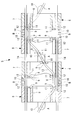
- FIG. 3 is a side view showing a state where the bending portion of FIG. 2 is bent in one direction.
- FIG. 3 is a side view showing a state where the bending portion of FIG. 2 is bent in one direction.
- FIG. 3 is a perspective view which shows an example of the top which comprises the curved part of FIG.
- FIG. 5 is a figure explaining the displacement of a wire when the top of FIG. 5 rocks.
- the manipulator 1 according to an embodiment of the present invention will be described below with reference to the drawings.
- the manipulator 1 according to the present embodiment is disposed at an elongated portion 2, an end effector 3 disposed at the distal end of the elongated portion 2, and a proximal end of the elongated portion 2.
- a drive unit 4 that generates power to the end effector 3 and a wire (see FIG. 2) 13 that transmits the power generated in the drive unit 4 to the end effector 3 are provided.
- the end effector 3 is, for example, a grip part that constitutes a grip forceps.
- the long portion 2 includes a bending portion 5 for changing the posture of the end effector 3 in the vicinity of the tip.
- the bending portion 5 includes a plurality of cylindrical pieces (node rings) 6 arranged in a direction along the central axis of the long portion 2, and adjacent pieces 6 are arranged together.
- a plurality of swing axes A and B that are twisted with respect to each other are connected so as to be swingable.
- a bending portion 5 that can freely change the posture of the end effector 3 is configured by the top 6.
- each of the tops 6 includes a cylindrical outer wall portion 7, and a cylindrical inner wall portion 8 disposed concentrically with a space inward in the radial direction of the outer wall portion 7.
- the connecting portion 9 is provided to connect the outer wall portion 7 and the inner wall portion 8 in the radial direction.
- a pair of protrusions 10 for connecting adjacent pieces 6 by swinging axis lines A and B are disposed on both ends of each piece 6 in the direction of the central axis with the central axis interposed therebetween, respectively. Protruding in the direction.
- the protrusions 10 at both ends in the central axis direction of each frame 6 have a circumferential phase difference of 90 °. As a result, the two swing axes A and B are twisted relative to each other.
- the protrusions 10 connected by the swing axes A and B of the two adjacent pieces 6 have different radial positions so as to be arranged in the radial direction.
- the connecting portion 9 is a strip-like portion extending in the radial direction with the direction along the central axis as the plate thickness direction in the same phase as the projection portion 10, and includes a through hole 11 penetrating in the plate thickness direction. . Since the protrusions 10 disposed at both ends of each frame 6 are disposed at positions where the phases are different by 90 °, the connecting portions 9 are also disposed at a phase different by 90 °.
- reference numeral 12 denotes a through-hole through which four wires 14 for bending the bending portion 5 by tension are passed.
- the wire 13 that has passed through the through hole 11 of one connecting portion 9 of each piece 6 passes through the through hole 11 of another connecting portion 9 having a phase difference of 90 °. Since the protrusions 10 connected by the same swing axis A, B of the adjacent pieces 6 are arranged in the same phase, the connecting part 9 is also arranged in the same phase. Accordingly, the wire 13 passes through the position intersecting the swing axis A and B between these connecting portions 9 by passing through the two connecting portions 9 of the adjacent tops 6 arranged in the same phase. It is supposed to be made.
- the wire 13 is formed in a spiral shape that turns in one direction around the central axis by sequentially passing through the through-holes 11 that are arranged at positions shifted in the same direction. They are arranged in a form.
- the manipulator 1 according to this embodiment can swing a plurality of pieces 6 arranged in the central axis direction around swinging axis lines A and B in which adjacent pieces 6 are arranged in a twisted positional relationship with each other. Since the bending portion 5 connected in this manner is provided, the end effector 3 disposed at the distal end of the long portion 2 can be adjusted by adjusting the swing angles of the bending portion 5 around the swing axes A and B. The posture can be changed freely.
- the movable portion of the wire 13 by bending the bending portion 5 is disposed only in the vicinity of the swing axes A and B, and the other portions of the wire 13 are not displaced. For this reason, even if the piece 6 is relatively swung around all the swinging axes A and B, only a bending force acts on the wire 13 and no tension or compressive force acts on the wire 13. It is possible to effectively prevent the path length difference from occurring in the wire 13 of the book.
- the drive unit 4 may be one driven by a motor, or one driven by manual operation.
- the wire 13 for driving the end effector 3 is disposed along the cylindrical gap between the outer wall portion 7 and the inner wall portion 8 formed in a double tubular shape, About the inner side of the inner wall portion 8, a continuous space near the central axis can be secured, and the wiring and piping to the end effector 3 can be effectively used to pass through without being obstructed by the wire 13. .
- the present invention is not limited thereto. Instead, the magnitude of the phase may be arbitrary.
Abstract
La présente invention a pour but d'améliorer la maniabilité sans générer de différences dans les longueurs de trajet de multiples fils destinés à entraîner un effecteur terminal même si une section longue est courbée dans une direction. Pour atteindre ce but, l'invention concerne un manipulateur (1) qui est pourvu : d'une longue section effilée (2), d'un effecteur terminal (3) disposé sur l'extrémité avant de la section longue (2), d'une section d'entraînement (4) disposée sur l'extrémité base de la section longue (2), et d'au moins un fil afin de transmettre la puissance générée dans la section d'entraînement (4) à l'effecteur d'extrémité (3). La section longue (2) est pourvue d'une partie courbure (5) dans laquelle de multiples pièces, qui sont disposées le long de son axe central, sont reliées afin que des pièces adjacentes puissent pivoter autour d'axes de pivot, qui sont disposés de manière à se trouver dans une relation de position torsadée les uns par rapport aux autres. Le fil est disposé de manière à traverser les positions d'intersection, chaque axe de pivotement étant en une position qui est décalée par rapport à l'axe central dans la direction radiale.
Priority Applications (2)
| Application Number | Priority Date | Filing Date | Title |
|---|---|---|---|
| PCT/JP2017/021932 WO2018229889A1 (fr) | 2017-06-14 | 2017-06-14 | Manipulateur |
| US16/710,088 US11203114B2 (en) | 2017-06-14 | 2019-12-11 | Manipulator |
Applications Claiming Priority (1)
| Application Number | Priority Date | Filing Date | Title |
|---|---|---|---|
| PCT/JP2017/021932 WO2018229889A1 (fr) | 2017-06-14 | 2017-06-14 | Manipulateur |
Related Child Applications (1)
| Application Number | Title | Priority Date | Filing Date |
|---|---|---|---|
| US16/710,088 Continuation US11203114B2 (en) | 2017-06-14 | 2019-12-11 | Manipulator |
Publications (1)
| Publication Number | Publication Date |
|---|---|
| WO2018229889A1 true WO2018229889A1 (fr) | 2018-12-20 |
Family
ID=64659162
Family Applications (1)
| Application Number | Title | Priority Date | Filing Date |
|---|---|---|---|
| PCT/JP2017/021932 WO2018229889A1 (fr) | 2017-06-14 | 2017-06-14 | Manipulateur |
Country Status (2)
| Country | Link |
|---|---|
| US (1) | US11203114B2 (fr) |
| WO (1) | WO2018229889A1 (fr) |
Cited By (5)
| Publication number | Priority date | Publication date | Assignee | Title |
|---|---|---|---|---|
| CN111941405A (zh) * | 2020-08-25 | 2020-11-17 | 长沙理工大学 | 一种丝驱动蛇形臂机器人 |
| CN111941406A (zh) * | 2020-08-25 | 2020-11-17 | 长沙理工大学 | 一种机器人系统 |
| CN111941404A (zh) * | 2020-08-25 | 2020-11-17 | 长沙理工大学 | 一种机器人系统的工作方法 |
| CN111941410A (zh) * | 2020-08-25 | 2020-11-17 | 长沙理工大学 | 一种避免松弛式丝驱动机器人 |
| CN113100949A (zh) * | 2021-04-16 | 2021-07-13 | 天津大学医疗机器人与智能系统研究院 | 手术机器人用前端执行装置 |
Families Citing this family (125)
| Publication number | Priority date | Publication date | Assignee | Title |
|---|---|---|---|---|
| US9060770B2 (en) | 2003-05-20 | 2015-06-23 | Ethicon Endo-Surgery, Inc. | Robotically-driven surgical instrument with E-beam driver |
| US20070084897A1 (en) | 2003-05-20 | 2007-04-19 | Shelton Frederick E Iv | Articulating surgical stapling instrument incorporating a two-piece e-beam firing mechanism |
| US11896225B2 (en) | 2004-07-28 | 2024-02-13 | Cilag Gmbh International | Staple cartridge comprising a pan |
| US10159482B2 (en) | 2005-08-31 | 2018-12-25 | Ethicon Llc | Fastener cartridge assembly comprising a fixed anvil and different staple heights |
| US11246590B2 (en) | 2005-08-31 | 2022-02-15 | Cilag Gmbh International | Staple cartridge including staple drivers having different unfired heights |
| US7669746B2 (en) | 2005-08-31 | 2010-03-02 | Ethicon Endo-Surgery, Inc. | Staple cartridges for forming staples having differing formed staple heights |
| US8186555B2 (en) | 2006-01-31 | 2012-05-29 | Ethicon Endo-Surgery, Inc. | Motor-driven surgical cutting and fastening instrument with mechanical closure system |
| US7845537B2 (en) | 2006-01-31 | 2010-12-07 | Ethicon Endo-Surgery, Inc. | Surgical instrument having recording capabilities |
| US11793518B2 (en) | 2006-01-31 | 2023-10-24 | Cilag Gmbh International | Powered surgical instruments with firing system lockout arrangements |
| US8708213B2 (en) | 2006-01-31 | 2014-04-29 | Ethicon Endo-Surgery, Inc. | Surgical instrument having a feedback system |
| US10568652B2 (en) | 2006-09-29 | 2020-02-25 | Ethicon Llc | Surgical staples having attached drivers of different heights and stapling instruments for deploying the same |
| US8684253B2 (en) | 2007-01-10 | 2014-04-01 | Ethicon Endo-Surgery, Inc. | Surgical instrument with wireless communication between a control unit of a robotic system and remote sensor |
| US8540128B2 (en) | 2007-01-11 | 2013-09-24 | Ethicon Endo-Surgery, Inc. | Surgical stapling device with a curved end effector |
| US8931682B2 (en) | 2007-06-04 | 2015-01-13 | Ethicon Endo-Surgery, Inc. | Robotically-controlled shaft based rotary drive systems for surgical instruments |
| US11857181B2 (en) | 2007-06-04 | 2024-01-02 | Cilag Gmbh International | Robotically-controlled shaft based rotary drive systems for surgical instruments |
| US11849941B2 (en) | 2007-06-29 | 2023-12-26 | Cilag Gmbh International | Staple cartridge having staple cavities extending at a transverse angle relative to a longitudinal cartridge axis |
| RU2493788C2 (ru) | 2008-02-14 | 2013-09-27 | Этикон Эндо-Серджери, Инк. | Хирургический режущий и крепежный инструмент, имеющий радиочастотные электроды |
| US9005230B2 (en) | 2008-09-23 | 2015-04-14 | Ethicon Endo-Surgery, Inc. | Motorized surgical instrument |
| US11648005B2 (en) | 2008-09-23 | 2023-05-16 | Cilag Gmbh International | Robotically-controlled motorized surgical instrument with an end effector |
| US9386983B2 (en) | 2008-09-23 | 2016-07-12 | Ethicon Endo-Surgery, Llc | Robotically-controlled motorized surgical instrument |
| US8210411B2 (en) | 2008-09-23 | 2012-07-03 | Ethicon Endo-Surgery, Inc. | Motor-driven surgical cutting instrument |
| US8608045B2 (en) | 2008-10-10 | 2013-12-17 | Ethicon Endo-Sugery, Inc. | Powered surgical cutting and stapling apparatus with manually retractable firing system |
| US10945731B2 (en) | 2010-09-30 | 2021-03-16 | Ethicon Llc | Tissue thickness compensator comprising controlled release and expansion |
| US9861361B2 (en) | 2010-09-30 | 2018-01-09 | Ethicon Llc | Releasable tissue thickness compensator and fastener cartridge having the same |
| US11849952B2 (en) | 2010-09-30 | 2023-12-26 | Cilag Gmbh International | Staple cartridge comprising staples positioned within a compressible portion thereof |
| US9629814B2 (en) | 2010-09-30 | 2017-04-25 | Ethicon Endo-Surgery, Llc | Tissue thickness compensator configured to redistribute compressive forces |
| US11812965B2 (en) | 2010-09-30 | 2023-11-14 | Cilag Gmbh International | Layer of material for a surgical end effector |
| US9320523B2 (en) | 2012-03-28 | 2016-04-26 | Ethicon Endo-Surgery, Llc | Tissue thickness compensator comprising tissue ingrowth features |
| BR112013027794B1 (pt) | 2011-04-29 | 2020-12-15 | Ethicon Endo-Surgery, Inc | Conjunto de cartucho de grampos |
| RU2014143258A (ru) | 2012-03-28 | 2016-05-20 | Этикон Эндо-Серджери, Инк. | Компенсатор толщины ткани, содержащий множество слоев |
| RU2639857C2 (ru) | 2012-03-28 | 2017-12-22 | Этикон Эндо-Серджери, Инк. | Компенсатор толщины ткани, содержащий капсулу для среды с низким давлением |
| US9101358B2 (en) | 2012-06-15 | 2015-08-11 | Ethicon Endo-Surgery, Inc. | Articulatable surgical instrument comprising a firing drive |
| US20140001231A1 (en) | 2012-06-28 | 2014-01-02 | Ethicon Endo-Surgery, Inc. | Firing system lockout arrangements for surgical instruments |
| US9289256B2 (en) | 2012-06-28 | 2016-03-22 | Ethicon Endo-Surgery, Llc | Surgical end effectors having angled tissue-contacting surfaces |
| BR112015021098B1 (pt) | 2013-03-01 | 2022-02-15 | Ethicon Endo-Surgery, Inc | Cobertura para uma junta de articulação e instrumento cirúrgico |
| BR112015026109B1 (pt) | 2013-04-16 | 2022-02-22 | Ethicon Endo-Surgery, Inc | Instrumento cirúrgico |
| US9283054B2 (en) | 2013-08-23 | 2016-03-15 | Ethicon Endo-Surgery, Llc | Interactive displays |
| US20150297225A1 (en) | 2014-04-16 | 2015-10-22 | Ethicon Endo-Surgery, Inc. | Fastener cartridges including extensions having different configurations |
| CN106456159B (zh) | 2014-04-16 | 2019-03-08 | 伊西康内外科有限责任公司 | 紧固件仓组件和钉保持器盖布置结构 |
| BR112016023698B1 (pt) | 2014-04-16 | 2022-07-26 | Ethicon Endo-Surgery, Llc | Cartucho de prendedores para uso com um instrumento cirúrgico |
| US10111679B2 (en) | 2014-09-05 | 2018-10-30 | Ethicon Llc | Circuitry and sensors for powered medical device |
| BR112017004361B1 (pt) | 2014-09-05 | 2023-04-11 | Ethicon Llc | Sistema eletrônico para um instrumento cirúrgico |
| US9924944B2 (en) | 2014-10-16 | 2018-03-27 | Ethicon Llc | Staple cartridge comprising an adjunct material |
| US10517594B2 (en) | 2014-10-29 | 2019-12-31 | Ethicon Llc | Cartridge assemblies for surgical staplers |
| US10085748B2 (en) | 2014-12-18 | 2018-10-02 | Ethicon Llc | Locking arrangements for detachable shaft assemblies with articulatable surgical end effectors |
| MX2017008108A (es) | 2014-12-18 | 2018-03-06 | Ethicon Llc | Instrumento quirurgico con un yunque que puede moverse de manera selectiva sobre un eje discreto no movil con relacion a un cartucho de grapas. |
| US11154301B2 (en) | 2015-02-27 | 2021-10-26 | Cilag Gmbh International | Modular stapling assembly |
| US10441279B2 (en) | 2015-03-06 | 2019-10-15 | Ethicon Llc | Multiple level thresholds to modify operation of powered surgical instruments |
| US10433844B2 (en) | 2015-03-31 | 2019-10-08 | Ethicon Llc | Surgical instrument with selectively disengageable threaded drive systems |
| US10105139B2 (en) | 2015-09-23 | 2018-10-23 | Ethicon Llc | Surgical stapler having downstream current-based motor control |
| US11890015B2 (en) | 2015-09-30 | 2024-02-06 | Cilag Gmbh International | Compressible adjunct with crossing spacer fibers |
| US20170086829A1 (en) | 2015-09-30 | 2017-03-30 | Ethicon Endo-Surgery, Llc | Compressible adjunct with intermediate supporting structures |
| US10292704B2 (en) | 2015-12-30 | 2019-05-21 | Ethicon Llc | Mechanisms for compensating for battery pack failure in powered surgical instruments |
| US11213293B2 (en) | 2016-02-09 | 2022-01-04 | Cilag Gmbh International | Articulatable surgical instruments with single articulation link arrangements |
| US10448948B2 (en) | 2016-02-12 | 2019-10-22 | Ethicon Llc | Mechanisms for compensating for drivetrain failure in powered surgical instruments |
| US10357247B2 (en) | 2016-04-15 | 2019-07-23 | Ethicon Llc | Surgical instrument with multiple program responses during a firing motion |
| US20170296173A1 (en) | 2016-04-18 | 2017-10-19 | Ethicon Endo-Surgery, Llc | Method for operating a surgical instrument |
| US20180168625A1 (en) | 2016-12-21 | 2018-06-21 | Ethicon Endo-Surgery, Llc | Surgical stapling instruments with smart staple cartridges |
| US10675026B2 (en) | 2016-12-21 | 2020-06-09 | Ethicon Llc | Methods of stapling tissue |
| JP7010956B2 (ja) | 2016-12-21 | 2022-01-26 | エシコン エルエルシー | 組織をステープル留めする方法 |
| US10307170B2 (en) | 2017-06-20 | 2019-06-04 | Ethicon Llc | Method for closed loop control of motor velocity of a surgical stapling and cutting instrument |
| US10881399B2 (en) | 2017-06-20 | 2021-01-05 | Ethicon Llc | Techniques for adaptive control of motor velocity of a surgical stapling and cutting instrument |
| US10779820B2 (en) | 2017-06-20 | 2020-09-22 | Ethicon Llc | Systems and methods for controlling motor speed according to user input for a surgical instrument |
| USD906355S1 (en) | 2017-06-28 | 2020-12-29 | Ethicon Llc | Display screen or portion thereof with a graphical user interface for a surgical instrument |
| US11000279B2 (en) | 2017-06-28 | 2021-05-11 | Ethicon Llc | Surgical instrument comprising an articulation system ratio |
| US10932772B2 (en) | 2017-06-29 | 2021-03-02 | Ethicon Llc | Methods for closed loop velocity control for robotic surgical instrument |
| US11944300B2 (en) | 2017-08-03 | 2024-04-02 | Cilag Gmbh International | Method for operating a surgical system bailout |
| US10779826B2 (en) | 2017-12-15 | 2020-09-22 | Ethicon Llc | Methods of operating surgical end effectors |
| US10682134B2 (en) | 2017-12-21 | 2020-06-16 | Ethicon Llc | Continuous use self-propelled stapling instrument |
| JP7005773B2 (ja) * | 2018-01-04 | 2022-01-24 | コヴィディエン リミテッド パートナーシップ | トルク伝達および機械的操作を伴う高関節運動リストアセンブリを含むロボット手術器具 |
| US11458641B2 (en) * | 2018-05-23 | 2022-10-04 | General Electric Company | Robotic arm assembly construction |
| US11207065B2 (en) | 2018-08-20 | 2021-12-28 | Cilag Gmbh International | Method for fabricating surgical stapler anvils |
| US11696761B2 (en) | 2019-03-25 | 2023-07-11 | Cilag Gmbh International | Firing drive arrangements for surgical systems |
| US11903581B2 (en) | 2019-04-30 | 2024-02-20 | Cilag Gmbh International | Methods for stapling tissue using a surgical instrument |
| US11771419B2 (en) | 2019-06-28 | 2023-10-03 | Cilag Gmbh International | Packaging for a replaceable component of a surgical stapling system |
| US11684434B2 (en) | 2019-06-28 | 2023-06-27 | Cilag Gmbh International | Surgical RFID assemblies for instrument operational setting control |
| US11660163B2 (en) | 2019-06-28 | 2023-05-30 | Cilag Gmbh International | Surgical system with RFID tags for updating motor assembly parameters |
| US11229437B2 (en) | 2019-06-28 | 2022-01-25 | Cilag Gmbh International | Method for authenticating the compatibility of a staple cartridge with a surgical instrument |
| US11701111B2 (en) | 2019-12-19 | 2023-07-18 | Cilag Gmbh International | Method for operating a surgical stapling instrument |
| US11844520B2 (en) | 2019-12-19 | 2023-12-19 | Cilag Gmbh International | Staple cartridge comprising driver retention members |
| US11864756B2 (en) | 2020-07-28 | 2024-01-09 | Cilag Gmbh International | Surgical instruments with flexible ball chain drive arrangements |
| US11931025B2 (en) | 2020-10-29 | 2024-03-19 | Cilag Gmbh International | Surgical instrument comprising a releasable closure drive lock |
| US11779330B2 (en) | 2020-10-29 | 2023-10-10 | Cilag Gmbh International | Surgical instrument comprising a jaw alignment system |
| US11896217B2 (en) | 2020-10-29 | 2024-02-13 | Cilag Gmbh International | Surgical instrument comprising an articulation lock |
| USD1013170S1 (en) | 2020-10-29 | 2024-01-30 | Cilag Gmbh International | Surgical instrument assembly |
| US11844518B2 (en) | 2020-10-29 | 2023-12-19 | Cilag Gmbh International | Method for operating a surgical instrument |
| US11744581B2 (en) | 2020-12-02 | 2023-09-05 | Cilag Gmbh International | Powered surgical instruments with multi-phase tissue treatment |
| US11653920B2 (en) | 2020-12-02 | 2023-05-23 | Cilag Gmbh International | Powered surgical instruments with communication interfaces through sterile barrier |
| US11737751B2 (en) | 2020-12-02 | 2023-08-29 | Cilag Gmbh International | Devices and methods of managing energy dissipated within sterile barriers of surgical instrument housings |
| US11944296B2 (en) | 2020-12-02 | 2024-04-02 | Cilag Gmbh International | Powered surgical instruments with external connectors |
| US11849943B2 (en) | 2020-12-02 | 2023-12-26 | Cilag Gmbh International | Surgical instrument with cartridge release mechanisms |
| US11890010B2 (en) | 2020-12-02 | 2024-02-06 | Cllag GmbH International | Dual-sided reinforced reload for surgical instruments |
| US11653915B2 (en) | 2020-12-02 | 2023-05-23 | Cilag Gmbh International | Surgical instruments with sled location detection and adjustment features |
| US11701113B2 (en) | 2021-02-26 | 2023-07-18 | Cilag Gmbh International | Stapling instrument comprising a separate power antenna and a data transfer antenna |
| US11925349B2 (en) | 2021-02-26 | 2024-03-12 | Cilag Gmbh International | Adjustment to transfer parameters to improve available power |
| US11730473B2 (en) | 2021-02-26 | 2023-08-22 | Cilag Gmbh International | Monitoring of manufacturing life-cycle |
| US11751869B2 (en) | 2021-02-26 | 2023-09-12 | Cilag Gmbh International | Monitoring of multiple sensors over time to detect moving characteristics of tissue |
| US11723657B2 (en) | 2021-02-26 | 2023-08-15 | Cilag Gmbh International | Adjustable communication based on available bandwidth and power capacity |
| US11950777B2 (en) | 2021-02-26 | 2024-04-09 | Cilag Gmbh International | Staple cartridge comprising an information access control system |
| US11812964B2 (en) | 2021-02-26 | 2023-11-14 | Cilag Gmbh International | Staple cartridge comprising a power management circuit |
| US11744583B2 (en) | 2021-02-26 | 2023-09-05 | Cilag Gmbh International | Distal communication array to tune frequency of RF systems |
| US11749877B2 (en) | 2021-02-26 | 2023-09-05 | Cilag Gmbh International | Stapling instrument comprising a signal antenna |
| US11696757B2 (en) | 2021-02-26 | 2023-07-11 | Cilag Gmbh International | Monitoring of internal systems to detect and track cartridge motion status |
| US11793514B2 (en) | 2021-02-26 | 2023-10-24 | Cilag Gmbh International | Staple cartridge comprising sensor array which may be embedded in cartridge body |
| US11717291B2 (en) | 2021-03-22 | 2023-08-08 | Cilag Gmbh International | Staple cartridge comprising staples configured to apply different tissue compression |
| US11723658B2 (en) | 2021-03-22 | 2023-08-15 | Cilag Gmbh International | Staple cartridge comprising a firing lockout |
| US11759202B2 (en) | 2021-03-22 | 2023-09-19 | Cilag Gmbh International | Staple cartridge comprising an implantable layer |
| US11806011B2 (en) | 2021-03-22 | 2023-11-07 | Cilag Gmbh International | Stapling instrument comprising tissue compression systems |
| US11826042B2 (en) | 2021-03-22 | 2023-11-28 | Cilag Gmbh International | Surgical instrument comprising a firing drive including a selectable leverage mechanism |
| US11737749B2 (en) | 2021-03-22 | 2023-08-29 | Cilag Gmbh International | Surgical stapling instrument comprising a retraction system |
| US11826012B2 (en) | 2021-03-22 | 2023-11-28 | Cilag Gmbh International | Stapling instrument comprising a pulsed motor-driven firing rack |
| US11786239B2 (en) | 2021-03-24 | 2023-10-17 | Cilag Gmbh International | Surgical instrument articulation joint arrangements comprising multiple moving linkage features |
| US11896218B2 (en) | 2021-03-24 | 2024-02-13 | Cilag Gmbh International | Method of using a powered stapling device |
| US11744603B2 (en) * | 2021-03-24 | 2023-09-05 | Cilag Gmbh International | Multi-axis pivot joints for surgical instruments and methods for manufacturing same |
| US11849944B2 (en) | 2021-03-24 | 2023-12-26 | Cilag Gmbh International | Drivers for fastener cartridge assemblies having rotary drive screws |
| US11786243B2 (en) | 2021-03-24 | 2023-10-17 | Cilag Gmbh International | Firing members having flexible portions for adapting to a load during a surgical firing stroke |
| US11857183B2 (en) | 2021-03-24 | 2024-01-02 | Cilag Gmbh International | Stapling assembly components having metal substrates and plastic bodies |
| US11896219B2 (en) | 2021-03-24 | 2024-02-13 | Cilag Gmbh International | Mating features between drivers and underside of a cartridge deck |
| US11793516B2 (en) | 2021-03-24 | 2023-10-24 | Cilag Gmbh International | Surgical staple cartridge comprising longitudinal support beam |
| US11903582B2 (en) | 2021-03-24 | 2024-02-20 | Cilag Gmbh International | Leveraging surfaces for cartridge installation |
| US11832816B2 (en) | 2021-03-24 | 2023-12-05 | Cilag Gmbh International | Surgical stapling assembly comprising nonplanar staples and planar staples |
| US11944336B2 (en) * | 2021-03-24 | 2024-04-02 | Cilag Gmbh International | Joint arrangements for multi-planar alignment and support of operational drive shafts in articulatable surgical instruments |
| US11849945B2 (en) | 2021-03-24 | 2023-12-26 | Cilag Gmbh International | Rotary-driven surgical stapling assembly comprising eccentrically driven firing member |
| US20220378424A1 (en) | 2021-05-28 | 2022-12-01 | Cilag Gmbh International | Stapling instrument comprising a firing lockout |
| US11937816B2 (en) | 2021-10-28 | 2024-03-26 | Cilag Gmbh International | Electrical lead arrangements for surgical instruments |
Citations (2)
| Publication number | Priority date | Publication date | Assignee | Title |
|---|---|---|---|---|
| WO2015093602A1 (fr) * | 2013-12-20 | 2015-06-25 | オリンパス株式会社 | Élément de guidage pour manipulateur flexible, et manipulateur flexible |
| JP2017512659A (ja) * | 2014-02-21 | 2017-05-25 | インテュイティブ サージカル オペレーションズ, インコーポレイテッド | 運動が拘束される関節運動可能部材、並びに関連する装置及び方法 |
Family Cites Families (5)
| Publication number | Priority date | Publication date | Assignee | Title |
|---|---|---|---|---|
| US7699835B2 (en) * | 2001-02-15 | 2010-04-20 | Hansen Medical, Inc. | Robotically controlled surgical instruments |
| US20030135204A1 (en) * | 2001-02-15 | 2003-07-17 | Endo Via Medical, Inc. | Robotically controlled medical instrument with a flexible section |
| JP2010017483A (ja) | 2008-07-14 | 2010-01-28 | Olympus Corp | 内視鏡湾曲管及び湾曲管を有する内視鏡 |
| JP2010259479A (ja) | 2009-04-30 | 2010-11-18 | Hoya Corp | 内視鏡用処置具 |
| US9339341B2 (en) | 2010-02-08 | 2016-05-17 | Intuitive Surgical Operations, Inc. | Direct pull surgical gripper |
-
2017
- 2017-06-14 WO PCT/JP2017/021932 patent/WO2018229889A1/fr active Application Filing
-
2019
- 2019-12-11 US US16/710,088 patent/US11203114B2/en active Active
Patent Citations (2)
| Publication number | Priority date | Publication date | Assignee | Title |
|---|---|---|---|---|
| WO2015093602A1 (fr) * | 2013-12-20 | 2015-06-25 | オリンパス株式会社 | Élément de guidage pour manipulateur flexible, et manipulateur flexible |
| JP2017512659A (ja) * | 2014-02-21 | 2017-05-25 | インテュイティブ サージカル オペレーションズ, インコーポレイテッド | 運動が拘束される関節運動可能部材、並びに関連する装置及び方法 |
Cited By (6)
| Publication number | Priority date | Publication date | Assignee | Title |
|---|---|---|---|---|
| CN111941405A (zh) * | 2020-08-25 | 2020-11-17 | 长沙理工大学 | 一种丝驱动蛇形臂机器人 |
| CN111941406A (zh) * | 2020-08-25 | 2020-11-17 | 长沙理工大学 | 一种机器人系统 |
| CN111941404A (zh) * | 2020-08-25 | 2020-11-17 | 长沙理工大学 | 一种机器人系统的工作方法 |
| CN111941410A (zh) * | 2020-08-25 | 2020-11-17 | 长沙理工大学 | 一种避免松弛式丝驱动机器人 |
| CN113100949A (zh) * | 2021-04-16 | 2021-07-13 | 天津大学医疗机器人与智能系统研究院 | 手术机器人用前端执行装置 |
| CN113100949B (zh) * | 2021-04-16 | 2022-03-29 | 天津大学医疗机器人与智能系统研究院 | 手术机器人用前端执行装置 |
Also Published As
| Publication number | Publication date |
|---|---|
| US20200114505A1 (en) | 2020-04-16 |
| US11203114B2 (en) | 2021-12-21 |
Similar Documents
| Publication | Publication Date | Title |
|---|---|---|
| WO2018229889A1 (fr) | Manipulateur | |
| US20210212785A1 (en) | Medical devices having smoothly articulating multi-cluster joints | |
| US9796092B2 (en) | Multi-articulated manipulator | |
| JP6022119B2 (ja) | 湾曲管及び湾曲管を備える内視鏡装置 | |
| CN100473870C (zh) | 动力传递机构和操纵装置 | |
| KR102111621B1 (ko) | 매니퓰레이터 | |
| JP2017533057A5 (fr) | ||
| US10173317B2 (en) | Multi-articulated manipulator | |
| JP2019530530A5 (fr) | ||
| JP5897109B2 (ja) | 制御装置 | |
| US20120330287A1 (en) | Surgical instrument | |
| WO2017006373A1 (fr) | Articulation de bras robotisé, et appareil chirurgical | |
| JP2008068070A5 (fr) | ||
| JP2013510684A5 (fr) | ||
| JP2014529460A (ja) | 改善された関節部を有する最小侵襲手術器具 | |
| JP2019500942A5 (fr) | ||
| JP2020524576A5 (fr) | ||
| WO2015190185A1 (fr) | Manipulateur | |
| JP2020524567A5 (fr) | ||
| JP2006192523A (ja) | 多関節指機構 | |
| US11745361B2 (en) | Manipulator and joint structure thereof | |
| KR20120105888A (ko) | 다자유도의 능동형 유니버설 조인트 장치 | |
| WO2023008275A1 (fr) | Structure flexible et son procédé de production | |
| JPWO2018073949A1 (ja) | 揺動機構および把持具 | |
| JPWO2019116415A1 (ja) | 動力伝達機構および処置具 |
Legal Events
| Date | Code | Title | Description |
|---|---|---|---|
| 121 | Ep: the epo has been informed by wipo that ep was designated in this application |
Ref document number: 17914059 Country of ref document: EP Kind code of ref document: A1 |
|
| NENP | Non-entry into the national phase |
Ref country code: DE |
|
| 122 | Ep: pct application non-entry in european phase |
Ref document number: 17914059 Country of ref document: EP Kind code of ref document: A1 |
|
| NENP | Non-entry into the national phase |
Ref country code: JP |