WO2018225550A1 - 成形装置 - Google Patents
成形装置 Download PDFInfo
- Publication number
- WO2018225550A1 WO2018225550A1 PCT/JP2018/020279 JP2018020279W WO2018225550A1 WO 2018225550 A1 WO2018225550 A1 WO 2018225550A1 JP 2018020279 W JP2018020279 W JP 2018020279W WO 2018225550 A1 WO2018225550 A1 WO 2018225550A1
- Authority
- WO
- WIPO (PCT)
- Prior art keywords
- mold
- child
- die
- molding
- mother
- Prior art date
- Legal status (The legal status is an assumption and is not a legal conclusion. Google has not performed a legal analysis and makes no representation as to the accuracy of the status listed.)
- Ceased
Links
Images



Classifications
-
- B—PERFORMING OPERATIONS; TRANSPORTING
- B29—WORKING OF PLASTICS; WORKING OF SUBSTANCES IN A PLASTIC STATE IN GENERAL
- B29C—SHAPING OR JOINING OF PLASTICS; SHAPING OF MATERIAL IN A PLASTIC STATE, NOT OTHERWISE PROVIDED FOR; AFTER-TREATMENT OF THE SHAPED PRODUCTS, e.g. REPAIRING
- B29C45/00—Injection moulding, i.e. forcing the required volume of moulding material through a nozzle into a closed mould; Apparatus therefor
- B29C45/17—Component parts, details or accessories; Auxiliary operations
- B29C45/26—Moulds
- B29C45/2673—Moulds with exchangeable mould parts, e.g. cassette moulds
-
- B—PERFORMING OPERATIONS; TRANSPORTING
- B29—WORKING OF PLASTICS; WORKING OF SUBSTANCES IN A PLASTIC STATE IN GENERAL
- B29C—SHAPING OR JOINING OF PLASTICS; SHAPING OF MATERIAL IN A PLASTIC STATE, NOT OTHERWISE PROVIDED FOR; AFTER-TREATMENT OF THE SHAPED PRODUCTS, e.g. REPAIRING
- B29C33/00—Moulds or cores; Details thereof or accessories therefor
- B29C33/02—Moulds or cores; Details thereof or accessories therefor with incorporated heating or cooling means
- B29C33/04—Moulds or cores; Details thereof or accessories therefor with incorporated heating or cooling means using liquids, gas or steam
-
- B—PERFORMING OPERATIONS; TRANSPORTING
- B29—WORKING OF PLASTICS; WORKING OF SUBSTANCES IN A PLASTIC STATE IN GENERAL
- B29C—SHAPING OR JOINING OF PLASTICS; SHAPING OF MATERIAL IN A PLASTIC STATE, NOT OTHERWISE PROVIDED FOR; AFTER-TREATMENT OF THE SHAPED PRODUCTS, e.g. REPAIRING
- B29C45/00—Injection moulding, i.e. forcing the required volume of moulding material through a nozzle into a closed mould; Apparatus therefor
- B29C45/17—Component parts, details or accessories; Auxiliary operations
- B29C45/72—Heating or cooling
- B29C45/73—Heating or cooling of the mould
- B29C45/7331—Heat transfer elements, e.g. heat pipes
-
- B—PERFORMING OPERATIONS; TRANSPORTING
- B29—WORKING OF PLASTICS; WORKING OF SUBSTANCES IN A PLASTIC STATE IN GENERAL
- B29K—INDEXING SCHEME ASSOCIATED WITH SUBCLASSES B29B, B29C OR B29D, RELATING TO MOULDING MATERIALS OR TO MATERIALS FOR MOULDS, REINFORCEMENTS, FILLERS OR PREFORMED PARTS, e.g. INSERTS
- B29K2905/00—Use of metals, their alloys or their compounds, as mould material
Definitions
- the present invention relates to a molding apparatus incorporating a temperature adjusting pipe.
- a molten resin is injected into a mold cavity, and after the resin is solidified, the mold can be released to take out a molded product.
- many kinds of molded products are increasing.
- the cost of a small lot of products will increase. It also takes time to make the mold. Therefore, a cassette type technology has been developed that allows a common part of the mold to be held by the mother mold and a child mold having a product-specific part (cavity shape) to be replaced.
- the cassette type technology it is possible to reduce the mold production cost and time for each product, and the cassette type technology is effective especially for small lot products because the ratio of mold depreciation to the part cost is large. It is said.
- Patent Document 1 discloses a configuration in which a cooling water channel is provided only on the mother die side in a molding apparatus using a cassette type technique. Specifically, a temperature control block made of a highly heat conductive substance is urged to the mother die by the urging means, and this temperature control block includes a cooling water channel as a temperature adjustment means.
- the child mold is mounted in the housing recess of the mother mold, and is sandwiched with both side surfaces in close contact with the side surface of the temperature control block. The temperature in the vicinity of the cavity of the child mold is stabilized by heat transfer from the temperature control block of the mother mold. According to the technique of Patent Document 1, since the temperature adjusting means is not provided in the child mold, troublesome work such as pipe connection at the time of replacing the child mold is not required, leading to a reduction in setup time.
- Patent Document 1 The technology of Patent Document 1 is effective in an ideal state, but there are actually problems to be overcome. That is, when the mother die and the child die are brought into close contact with each other, the members in contact with each other are pressed to form a close contact state, but there are cases in which the close contact state cannot be secured during molding for various reasons as described below. . If the mother die and the child die are not in close contact with each other, air having high heat insulation properties is interposed between them, and the heat conduction efficiency between the mother die and the child die is greatly reduced. Thereby, the temperature adjustment effect by the piping provided in the mother die does not reach the child die, and there is a possibility that the temperature adjustment near the cavity cannot be accurately performed.
- Patent Document 2 includes a cavity plate, a cavity insert, a core plate, and a core insert, and a predetermined clearance may be provided between the members, and an elastic material may be installed in the clearance.
- a resin molding die is disclosed.
- the elastic material disclosed in Patent Document 2 is intended to improve positioning accuracy between members and is not intended to adjust the temperature of the insert.
- the present invention has been made in view of the above circumstances, and while using a mother die attached in a replaceable manner, the temperature of the child die can be reduced without greatly increasing the manufacturing cost of the die and the trouble of replacement. It is an object of the present invention to provide a molding apparatus capable of effectively adjusting.
- the molding apparatus of the present invention comprises: A molding apparatus having a child mold and a mother mold attached to the child mold in an exchangeable manner,
- the mother die incorporates a pipe through which a temperature adjusting fluid flows, and between the child die and the mother die can be elastically deformed at least in contact with both the child die and the mother die at the time of molding.
- a heat transfer member is arranged.
- a molding apparatus capable of effectively adjusting the temperature of the child mold without using the manufacturing cost of the mold and the trouble of replacing the mold while using the mother mold attached to the daughter mold in a replaceable manner. Can be provided.
- FIG. 1A is a schematic cross-sectional view of a molding apparatus according to the present embodiment.
- the molding apparatus includes a fixed side mold 10, a fixed side mold 20, a movable side mold 30, a movable side mold 40, a temperature adjustment unit 50, a fixed side elastic member 60, and a movable side elastic member 70. And have.
- the stationary side mold 10 and the movable side mold 30 constitute a mother mold
- the stationary side mold 20 and the movable side mold 40 constitute a child mold
- the fixed side elastic member 60 and the movable side elastic member 70 are provided. It is an elastically deformable heat transfer member.
- the steel fixed side mother die 10 includes a fixed side receiving plate 11, a first frame 12 attached to the fixed side receiving plate 11, and a second frame 13 attached to the first frame 12. Inside the first frame 12, a pair of guide shafts 14 are planted on the fixed side receiving plate 11, and a slider plate 15 is disposed so as to be movable along the guide shafts 14. An eject pin 16 is planted on the slider plate 15. Further, a pipe 13 a extending in the circumferential direction is formed in a spiral shape in the second frame 13, and both ends thereof are connected to an external temperature adjustment unit 50 via a connection pipe 17.
- the fixed side mold 20 includes a first block 21 and a second block 22 inserted into the second frame 13 of the fixed side mold 10.
- a molding surface 22 a is formed on the movable side surface of the second block 22.
- the first block 21 and the second block 22 are formed with through holes 21a and 22b through which the eject pins 16 are inserted.
- the through hole 22b opens at the molding surface 22a.
- the fixed-side elastic member 60 is disposed so as to be in close contact with the inner peripheral surface of the second frame 13 and the outer peripheral surfaces of the first block 21 and the second block 22.
- the steel movable side mold 30 has a movable side receiving plate 31 and a third frame 32 attached to the movable side receiving plate 31.
- a pipe 32 a extending in the circumferential direction is formed in a spiral shape in the third frame body 32, and both ends thereof are connected to an external temperature adjustment unit 50 via a connection pipe 33.
- the movable side mold 40 has a third block 41 inserted into the third frame 32 of the movable side mold 30.
- a molding surface 41 a is formed on the fixed side surface of the third block 41.
- the fixed side die 20 and the movable side die 40 are preferably formed of any one of an aluminum alloy, a beryllium copper alloy, a zinc alloy, and an aluminum-ceramic composite material. This is because these materials have a thermal conductivity of 100 W / m ⁇ K or more and satisfy the strength required for an injection mold. If the thermal conductivity is 100 W / m ⁇ K or more, the heat transfer from the contact surface to the molding surface of the child mold is made more efficient and the mold temperature can be stabilized quickly. It is valid.
- a gap having a thickness t is formed on the entire circumference between the third frame 32 of the movable side mold 30 and the third block 41 of the movable side mold 40, and the movable side elastic member 70 is formed in the gap.
- the movable side elastic member 70 is formed in the gap.
- fixed side mold 20 and movable side mold 40 can be exchanged with another fixed side mold 20 ′ and movable side mold 40 ′.
- the fixed side die 20 ′ has a molding surface 22a ′ having a shape different from that of the molding surface 22a
- the movable side die 40 ′ has a molding surface 41a ′ having a shape different from that of the molding surface 41a. ing. More specifically, the replacement work will be described. From the assembled state shown in (a), the movable side base plate 30 including the movable side elastic member 70 and the third frame body 32 is integrally removed, and the disassembled state shown in (b).
- the fixed side die 20 and the movable side die 40 are integrally removed from the fixed side mother die 10. After this is replaced with another fixed side mold 20 ′ and a movable side mold 40 ′, it is assembled to the fixed base mold 10 as in the reassembled state shown in FIG.
- the movable side mold 30 including the third frame 32 is attached.
- the fixed side mold 20 before replacement and the fixed side mold 20 ′ after replacement have the same outer dimensions, and the movable side mold 40 before replacement and the movable side mold 40 ′ after replacement Since the outer dimensions are equal, only the child mold can be exchanged in the molding apparatus according to the present embodiment, and this makes it possible to cope with molding of various types of resin molded products while suppressing mold costs. Further, since the temperature adjusting pipe is not provided in the fixed side mold 20 and the movable side mold 40, the replacement can be performed quickly.
- the fixed-side elastic material 60 and the movable-side elastic material 70 are preferably rubber-like sheets and films because they can be easily processed and easily brought into surface contact, and are particularly preferably silicone heat conductive sheets. It is desirable that the fixed elastic member 60 and the movable elastic member 70 have a thickness of 0.1 mm or more and 5 mm or less, a thermal conductivity of 2 W / mK or more, and an elastic modulus of 1 GPa or less. If the thickness of the fixed-side elastic material 60 and the movable-side elastic material 70 exceeds 5 mm and is too thick, or if the thermal conductivity is too low so as to be less than 2 W / mK, the heat insulation of the elastic material itself may cause heat insulation between the mother die and the child die.
- the elastic modulus of the fixed-side elastic member 60 and the movable-side elastic member 70 exceeds 1 GPa or is too high, or if the thickness is less than 0.1 mm, the contact surface mismatch (displacement) may not be absorbed. .
- the specifications of the elastic material described above can absorb the inconsistency of the contact surface while reducing the influence of heat transfer as much as possible.
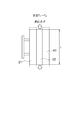
- FIG. 2 is a diagram in which the thermal expansion of the stationary side mold 20 and the movable side mold 40 is exaggerated by dotted lines when the temperature rises to the temperature at the time of molding with respect to room temperature.
- the same material is used for the first block 21, the second block 22, and the third block 41, and the fixed elastic member 60 and the movable elastic member 70 are the same material.
- the coefficient of linear expansion of the child mold material is a (/ K)
- the Young's modulus of the child mold material is Em (GPa)
- the Young's modulus (elastic modulus) of the elastic material is E (GPa).
- the dimension in the thickness direction of the material is L (mm), and the thickness of the elastic material is t (mm).
- the thickness direction of the elastic member refers to the heat transfer direction.
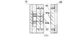
- 3A to 3C are diagrams showing a molding process of the molding apparatus, but the temperature adjustment unit is omitted.
- the temperature-adjusted liquid is supplied from the temperature adjustment unit 50 shown in FIG. 1A via the connection pipes 17 and 33 and the pipe 13a of the second frame 13 and the pipe 32a of the third frame 32, and the fixed side.
- the mother die 10 and the movable mother die 30 are adjusted so as to have a predetermined temperature.
- heat conduction is performed from the fixed side mold 10 in surface contact with each other to the fixed side mold 20 via the fixed elastic member 60, and the movable side mold 30 in surface contact with each other.
- heat conduction is performed from the movable side elastic material 70 to the movable side mold 40, so that the fixed side mold 20 and the movable side mold 40 can be adjusted to a temperature within a predetermined range.
- the movable side mold 30 and the movable side mold 40 are moved relative to the fixed side mold 10 and the fixed side mold 20, and the mold is clamped.
- a molten resin is injected into a cavity formed by the surface 22a and the movable molding surface 41a through a gate (not shown).
- heat conduction is performed from the fixed side mold 10 in surface contact with each other to the fixed side mold 20 via the fixed elastic member 60, and the movable side mold in surface contact with each other. Heat conduction is performed from 30 to the movable side die 40 via the movable side elastic member 70.
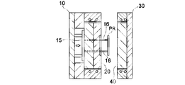
- the movable side die 30 and the movable side die 40 are separated from the fixed side die 10 and the fixed side die 20, and further as shown in FIG. 3C. Further, the molded resin molded product PR can be peeled off from the molding surface 22a by displacing the slider plate 15 and projecting the tip of the eject pin 16 to the movable side.
- the distance between the mother die and the child die is reduced by 0.2 mm due to the difference in thermal expansion between the mother die and the child die, but the elastic material absorbs this change. Because it can be in close contact without stretching, heat exchange can be performed efficiently between the two.
- the present inventor arranges the mother mold on both sides of the child mold and (a) contacts the mother mold on both sides of the child mold, and (b) one side of the child mold ( 4)
- the lower side in FIG. 4 is brought into contact with the mother die.
- a 1 mm gap is provided between the other side (upper side in FIG. 4) and the mother die
- one side of the child die is brought into contact with the mother die.
- an elastic material having a thickness of 3 mm is provided between the other side and the mother die and brought into contact with each other, the temperature distribution of the cross section was obtained.
- the thermal conductivity of the air layer was 0.02 W / mK
- the thermal conductivity of the elastic material was 10 W / mK
- the temperature of the entire master was adjusted to 40 ° C.
- the white part in the center of the child mold indicates a cavity and a gate.
- the fixed-side elastic member 60 is disposed between the fixed-side mother die 10 and the fixed-side child die 20, and the movable side between the movable-side mother die 30 and the movable-side child die 40 is movable.
- the elastic material 70 is disposed, the elastic material may be provided only on the movable side or the fixed side.
- the present invention is suitable for providing a molding apparatus incorporating a temperature adjusting pipe.
Landscapes
- Engineering & Computer Science (AREA)
- Mechanical Engineering (AREA)
- Manufacturing & Machinery (AREA)
- Physics & Mathematics (AREA)
- Thermal Sciences (AREA)
- Moulds For Moulding Plastics Or The Like (AREA)
Abstract
子型と、前記子型を交換可能に取り付けられた母型と、を有する成形装置は、前記母型が、温度調整用の流体が流れる配管を内蔵しており、前記子型と前記母型との間には、少なくとも成形時に前記子型と前記母型の双方に接触する弾性変形可能な熱伝達部材が配置されている。これにより、子型を交換可能に取り付けられた母型を用いながらも、金型の製造コストや交換時の手間を大きくかけることなく、子型の温度調整を有効に行える成形装置を提供することができる。
Description
本発明は、温度調整用の配管を内蔵した成形装置に関するものである。
一般的な射出成形装置においては、溶融樹脂を金型のキャビティ内に射出させ、樹脂が固化した後に、金型を離型して成形品を取り出すことができる。ところで最近の傾向として、多品種小ロットの成形品が増加している。多品種の樹脂製品を成形するには、形状が異なる製品ごとに金型を製作する必要があるが、製品毎に金型を製作していては、小ロットの製品のコストが増大し、また金型製作の時間もかかる。そこで、金型の共通部分を母型に持たせ、製品固有の部分(キャビティ形状)を持たせた子型を交換可能とする、カセット型の技術が開発された。カセット型の技術によって、製品ごとの金型製作コスト及び時間を抑制することができ、特に小ロット製品では、部品費に占める金型償却費の割合が大きいので、カセット型の技術が有効であるとされる。
ところで、成形時の金型温度によって成形品の寸法・形状が変化するので、特に精度が要求される樹脂製品の成形では、成形時の金型温度を安定させる必要がある。一般的な金型の温度調整は、金型内に冷却水路(配管)を設け、温度調整された液体(水、油)を流すことで行うことが多い。金型内で最も温度調整が必要とされるのは製品を形成するキャビティ付近のため、子型、または子型及び母型の両方に配管を設ける構成が一般的である。ところが、キャビティを構成する子型に温度調整用の配管を設けた場合、母型から子型を脱着する度に、配管の取り外しと再組み付けが必要になり、特に小ロットの成形品を成形する際には、子型の交換時間の占める割合が高くなり、生産効率が低下するという問題がある。
これに対し特許文献1には、カセット型技術を用いた成形装置において、母型側のみに冷却水路を設けた構成が開示されている。具体的には、高熱伝導性の物質からなる温調ブロックが付勢手段によって母型に付勢されており、この温調ブロックが温度調整手段としての冷却水路を備えている。子型は母型の収納凹部に装着されており、その両側面が温調ブロックの側面と密着した状態で挟持されている。子型のキャビティ付近の温度は、母型の温調ブロックからの伝熱によって安定化が図られている。特許文献1の技術によれば、子型に温度調整手段を設けていないので、子型交換時の配管接続などの面倒な作業を要せず、段取り時間の削減に繋がるとされる。
特許文献1の技術は理想状態では有効であるが、実際には克服すべき課題がある。すなわち、母型と子型とを密着させる際に、平面同士の部材を押し当てて密着状態を形成しているが、下記のような様々な理由で、成形時に密着状態を確保できないケースがある。母型と子型とが密着しなければ、その間に断熱性が高い空気が介在することとなり、母型と子型間での熱伝導効率は大きく低下する。これにより、母型に設けた配管による温度調整の効果が子型に及ばず、キャビティ付近の温度調整を精度良く行えない恐れがある。
[母型と子型とが密着しない理由]
(1)母型と子型の材料の線膨張係数が異なる場合、室温で母型と子型が密着していても、成形時に温度が変化すると両者は離れるか突っ張って、発生した応力で歪みが生じる恐れがある。母型と子型の材料の線膨張係数を同じにすれば、かかる問題を回避できるが、金型材料の選択の自由度が狭まる。
(2)子型が複数のプレートから成る場合、それぞれに寸法誤差があると、少なくとも一方の接続面に段差が生じ、相手が平面では隙間が生じる恐れがある。プレートの許容誤差を略ゼロにすれば、かかる問題を回避できるが、それにより子型の製作コストが膨大となる。
(3)例え室温で子型の接続面が高精度な平面であっても、成形時の子型の型温が均一でないと、熱膨張も均一で無くなり、接続面の形状に歪みが生じて平面度が大きく低下する恐れがある。
(1)母型と子型の材料の線膨張係数が異なる場合、室温で母型と子型が密着していても、成形時に温度が変化すると両者は離れるか突っ張って、発生した応力で歪みが生じる恐れがある。母型と子型の材料の線膨張係数を同じにすれば、かかる問題を回避できるが、金型材料の選択の自由度が狭まる。
(2)子型が複数のプレートから成る場合、それぞれに寸法誤差があると、少なくとも一方の接続面に段差が生じ、相手が平面では隙間が生じる恐れがある。プレートの許容誤差を略ゼロにすれば、かかる問題を回避できるが、それにより子型の製作コストが膨大となる。
(3)例え室温で子型の接続面が高精度な平面であっても、成形時の子型の型温が均一でないと、熱膨張も均一で無くなり、接続面の形状に歪みが生じて平面度が大きく低下する恐れがある。
以上の複合的な理由により、成形時において母型と子型の密着状態を維持することができず、それにより温度調整能力が低下することが多い。特に子型のサイズが大きいと母型との熱膨張の不一致が大きくなり、上記の課題が顕在化する傾向がある。
特許文献2には、キャビティプレートと、キャビティ入れ子と、コアプレートと、コア入れ子の各部材を備えてなり、部材間に所定のクリアランスを設けるとともに、クリアランス内に弾性材を設置してもよいとされる樹脂成形用金型が開示されている。しかしながら、特許文献2に開示された弾性材は、部材間の位置決め精度を向上させるものであって、入れ子の温度調整を目的とするものではない。
本発明は、上記事情に鑑みなされたものであり、子型を交換可能に取り付けられた母型を用いながらも、金型の製造コストや交換時の手間を大きくかけることなく、子型の温度調整を有効に行える成形装置を提供することを目的とする。
本発明の成形装置は、
子型と、前記子型を交換可能に取り付けられた母型と、を有する成形装置であって、
前記母型は、温度調整用の流体が流れる配管を内蔵しており、前記子型と前記母型との間には、少なくとも成形時に前記子型と前記母型の双方に接触する弾性変形可能な熱伝達部材が配置されているものである。
子型と、前記子型を交換可能に取り付けられた母型と、を有する成形装置であって、
前記母型は、温度調整用の流体が流れる配管を内蔵しており、前記子型と前記母型との間には、少なくとも成形時に前記子型と前記母型の双方に接触する弾性変形可能な熱伝達部材が配置されているものである。
本発明によれば、子型を交換可能に取り付けられた母型を用いながらも、金型の製造コストや交換時の手間を大きくかけることなく、子型の温度調整を有効に行える成形装置を提供することができる。
以下、添付した図面を参照しながら、本発明の実施形態を説明する。図1Aは、本実施の形態にかかる成形装置の概略断面図である。成形装置は、固定側母型10と、固定側子型20と、可動側母型30と、可動側子型40と、温度調整ユニット50と、固定側弾性材60と、可動側弾性材70とを有する。固定側母型10と可動側母型30とで母型を構成し、固定側子型20と可動側子型40とで子型を構成し、固定側弾性材60と可動側弾性材70が弾性変形可能な熱伝達部材である。
鋼製の固定側母型10は、固定側受け板11と、固定側受け板11に取り付けられる第1枠体12と、第1枠体12に取り付けられる第2枠体13とを有する。第1枠体12の内側において、固定側受け板11に一対のガイド軸14が植設され、ガイド軸14に沿って移動可能となるようにスライダ板15が配置されている。スライダ板15には、イジェクトピン16が植設されている。又、第2枠体13内には、周方向に延在する配管13aが螺旋状に形成されており、その両端は接続管17を介して外部の温度調整ユニット50に連結されている。
固定側子型20は、固定側母型10の第2枠体13の内部に挿入された第1ブロック21と第2ブロック22とを有する。第2ブロック22の可動側面に、成形面22aが形成されている。又、第1ブロック21と第2ブロック22には、イジェクトピン16を挿通させた貫通孔21a、22bが形成されている。貫通孔22bは成形面22aで開口している。
固定側母型10の第2枠体13と、固定側子型20の第1ブロック21と第2ブロック22との間には、全周において厚みtの隙間が形成されており、かかる隙間に固定側弾性材60が、第2枠体13の内周面及び、第1ブロック21と第2ブロック22の外周面とに密着するようにして配置されている。
鋼製の可動側母型30は、可動側受け板31と、可動側受け板31に取り付けられる第3枠体32とを有する。第3枠体32内には、周方向に延在する配管32aが螺旋状に形成されており、その両端は接続管33を介して外部の温度調整ユニット50に連結されている。
可動側子型40は、可動側母型30の第3枠体32の内部に挿入された第3ブロック41を有する。第3ブロック41の固定側面に、成形面41aが形成されている。尚、固定側子型20及び可動側子型40は、アルミニウム合金、ベリリウム銅合金、亜鉛合金、アルミニウム-セラミック複合材のいずれかにより形成されていると好ましい。これらの素材であれば、熱伝導率が100W/m・K以上であって、且つ射出成形金型として必要な強度を満たすからである。熱伝導率が100W/m・K以上であれば、子型の接触面から成形面までの伝熱が効率化され、型温安定化が迅速となるため、サイズの大きな子型に対しても有効である。
可動側母型30の第3枠体32と、可動側子型40の第3ブロック41との間には、全周において厚みtの隙間が形成されており、かかる隙間に可動側弾性材70が、第3枠体32の内周面、第3ブロック41の外周面とに密着するようにして配置されている。
図1Bを参照して、本実施の形態では、固定側子型20及び可動側子型40を、別の固定側子型20'及び可動側子型40'と交換可能となっている。ここで、固定側子型20'は、成形面22aとは異なる形状の成形面22a'を有し、可動側子型40'は、成形面41aとは異なる形状の成形面41a'を有している。より具体的に交換作業を説明すると、(a)に示す組立状態から、可動側弾性材70及び第3枠体32を含む可動側母型30を一体で取り外しつつ、(b)に示す分解状態のように固定側子型20と可動側子型40とを固定側母型10から一体的に取り外す。これを、別の固定側子型20'と可動側子型40'と交換した後、(c)に示す再組立状態のように固定側母型10に組み付けて、最後に可動側弾性材70及び第3枠体32を含む可動側母型30を取り付ける。交換前の固定側子型20と、交換後の固定側子型20'とは外寸が等しくなっており、また交換前の可動側子型40と、交換後の可動側子型40'とは外寸が等しくなっているので、本実施の形態にかかる成形装置において子型のみを交換でき、これにより金型コストを抑制しつつ多品種小ロットの樹脂成形品の成形に対応できる。又、固定側子型20及び可動側子型40には、温度調整用の配管を設けていないので、交換を迅速に行うことができる。
固定側弾性材60及び可動側弾性材70は、ゴム状のシートやフィルムであると加工が容易で面接触させやすいため好ましく、特にシリコーン製の熱伝導シートであると好ましい。固定側弾性材60及び可動側弾性材70の厚みは0.1mm以上、5mm以下、熱伝導率は2W/mK以上、弾性率1GPa以下が望ましい。固定側弾性材60及び可動側弾性材70の厚みが5mmを超えて厚すぎたり、2W/mKを下回るほど熱伝導率が低すぎると、弾性材自身の断熱により、母型と子型間の伝熱を阻害する恐れがある。一方、固定側弾性材60及び可動側弾性材70の弾性率が1GPaを超えて高すぎたり、厚みが0.1mmを下回って薄すぎると、接触面の不一致(ズレ)を吸収できない恐れがある。以上述べた弾性材の仕様が熱伝達の阻害影響を極力減らしつつ、接触面の不一致を吸収できる。
図2は、室温に対して成形時の温度まで上昇した際における固定側子型20及び可動側子型40の熱膨張を点線で誇張して示した図である。ここでは、第1ブロック21,第2ブロック22,第3ブロック41を構成する子型の素材を同じものとし、また固定側弾性材60及び可動側弾性材70の素材を同じものとする。子型の素材の線膨張係数をa(/K)、子型の素材のヤング率をEm(GPa)、弾性材の素材のヤング率(弾性率)をE(GPa)とし、子型における弾性材の厚み方向の寸法をL(mm)とし、弾性材の厚みをt(mm)とする。弾性部材の厚み方向は熱伝達方向をいうものとする。
子型の温度をT1からT2へと増大させたとき、子型に生じる熱応力Pは、
P=Em×(δ/L)、但しδ=a×(T2-T1)×L/2
と表せる。このとき、弾性材を変形させるのに必要な力Fが、子型の熱応力P未満(F<P)であれば、子型の熱膨張を弾性材で吸収できることとなる。この条件から、
E×(δ/t)<Em×(δ/L)
よって、
t>E/Em×L (1)
が成立することとなる。
P=Em×(δ/L)、但しδ=a×(T2-T1)×L/2
と表せる。このとき、弾性材を変形させるのに必要な力Fが、子型の熱応力P未満(F<P)であれば、子型の熱膨張を弾性材で吸収できることとなる。この条件から、
E×(δ/t)<Em×(δ/L)
よって、
t>E/Em×L (1)
が成立することとなる。
次に、本実施の形態にかかる成形装置の動作について説明する。図3A~図3Cは、成形装置の成形工程を示す図であるが、温度調整ユニットは省略して示している。図1Aに示す温度調整ユニット50から接続管17,33を介して、第2枠体13の配管13a及び第3枠体32の配管32aを介して、温度調整された液体が供給され、固定側母型10及び可動側母型30が所定温度になるように調整されている。このとき、相互に面接触してなる固定側母型10から固定側弾性材60を介して固定側子型20に熱伝導が行われ、又、相互に面接触してなる可動側母型30から可動側弾性材70を介して可動側子型40に熱伝導が行われ、これにより固定側子型20及び可動側子型40が所定範囲内の温度になるように調整することができる。
かかる状態で、図3Aに示すように、固定側母型10及び固定側子型20に対して、可動側母型30及び可動側子型40を相対移動させて型締めし、固定側の成形面22aと可動側の成形面41aとで形成されるキャビティ内に、不図示のゲートを介して溶融した樹脂を射出する。この時点でも、相互に面接触してなる固定側母型10から固定側弾性材60を介して固定側子型20に熱伝導が行われ、又、相互に面接触してなる可動側母型30から可動側弾性材70を介して可動側子型40に熱伝導が行われている。
キャビティ内の樹脂が固化した後、図3Bに示すように、固定側母型10及び固定側子型20から、可動側母型30及び可動側子型40を離間させ、更に図3Cに示すように、スライダ板15を変位させてイジェクトピン16の先端を可動側に突き出すことにより、成形された樹脂成形品PRを成形面22aから引きはがすことができる。
本発明者が作成した実施例(以下の仕様)にて、温度変化前後の寸法は以下の通りである。但し、寸法A,B,tは図1Aに図示する部位のものとする。
(a)子型の素材:アルミニウム合金A7075(線膨張係数23.6×10⁻⁶/K,熱伝導率130W/mK)
子型の外寸A:600mm(25℃において測定)
子型の外寸A:600.8mm(80℃において測定)
(b)母型の素材:鋼材S55C(線膨張係数11.7×10⁻⁶/K、熱伝導率46W/mK)
母型の内寸B:603mm(25℃において測定)
母型の内寸B:603.4mm(80℃において測定)
(c)弾性材の素材:シリコーンゴム製熱伝導シート(線膨張係数2×10⁻⁴/K、熱伝導率5W/mK)
弾性材の厚みt:3mm(25℃において測定)
弾性材の厚みt:2.8mm(80℃において母型、子型が熱膨張後に測定)
(a)子型の素材:アルミニウム合金A7075(線膨張係数23.6×10⁻⁶/K,熱伝導率130W/mK)
子型の外寸A:600mm(25℃において測定)
子型の外寸A:600.8mm(80℃において測定)
(b)母型の素材:鋼材S55C(線膨張係数11.7×10⁻⁶/K、熱伝導率46W/mK)
母型の内寸B:603mm(25℃において測定)
母型の内寸B:603.4mm(80℃において測定)
(c)弾性材の素材:シリコーンゴム製熱伝導シート(線膨張係数2×10⁻⁴/K、熱伝導率5W/mK)
弾性材の厚みt:3mm(25℃において測定)
弾性材の厚みt:2.8mm(80℃において母型、子型が熱膨張後に測定)
上記実施例によれば、母型と子型間の熱膨張差によって、母型と子型間の距離が0.2mm縮まるが、弾性材がこの変化を吸収するので、子型が母型内で突っ張ることなく密着できるので、両者の間で効率良く熱交換ができる。
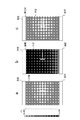
以下、本発明者が行ったシミュレーションについて説明する。本発明者は、図4に示すように、子型の両側に母型を配置した上で、(a)子型の両側で母型に接触させた場合、(b)子型の一方側(図4で下側)を母型に接触させるが、他方側(図4で上側)と母型との間に1mmの隙間を設けた場合、(c)子型の一方側を母型に接触させ、他方側と母型との間に厚さ3mmの弾性材を設けて両者に接触させた場合について、それぞれ断面の温度分布を求めた。ここで、空気層の熱伝導率を0.02W/mKとし、弾性材の熱伝導率を10W/mKとし、母型全体は40℃に温度調整されているものとした。尚、子型の中央にある白抜きの部位はキャビティ及びゲートを示している。
まず、図4の(a)に示すような理想的な接触状態では、バランスの良い温度分布となっている。一方、図4の(b)に示すように子型と母型との間に隙間を設けると、母型との間に隙間を設けた子型の一方側に母型から伝熱が十分になされず、母型と密着した子型の他方側に対して、温度勾配が大きくなり、高精度な成形を行えない恐れがある。これに対し、図4の(c)に示すように子型と母型との間に弾性材を設けると、弾性材を介して効率良く伝熱を行うことが出来、図4の(a)に示す理想的な接触状態の温度分布に近づくことが分かった。
以上述べた実施の形態では、固定側母型10と固定側子型20との間に固定側弾性材60を配置し、また可動側母型30と可動側子型40との間に可動側弾性材70を配置しているが、可動側又は固定側のみに弾性材を設けてもよい。
本発明は、温度調整用の配管を内蔵した成形装置を提供することに適している。
10 固定側母型
11 固定側受け板
12 第1枠体
13 第2枠体
13a 配管
14 ガイド軸
15 スライダ板
16 イジェクトピン
17 接続管
20 固定側子型
21 第1ブロック
21a 貫通孔
22 第2ブロック
22a 成形面
22b 貫通孔
30 可動側母型
31 可動側受け板
32 第3枠体
32a 配管
33 接続管
40 可動側子型
41 第3ブロック
41a 成形面
50 温度調整ユニット
60 固定側弾性材
70 可動側弾性材
11 固定側受け板
12 第1枠体
13 第2枠体
13a 配管
14 ガイド軸
15 スライダ板
16 イジェクトピン
17 接続管
20 固定側子型
21 第1ブロック
21a 貫通孔
22 第2ブロック
22a 成形面
22b 貫通孔
30 可動側母型
31 可動側受け板
32 第3枠体
32a 配管
33 接続管
40 可動側子型
41 第3ブロック
41a 成形面
50 温度調整ユニット
60 固定側弾性材
70 可動側弾性材
Claims (7)
- 子型と、前記子型を交換可能に取り付けられた母型と、を有する成形装置であって、
前記母型は、温度調整用の流体が流れる配管を内蔵しており、前記子型と前記母型との間には、少なくとも成形時に前記子型と前記母型の双方に接触する弾性変形可能な熱伝達部材が配置されている成形装置。 - 前記母型は、前記配管を内蔵したブロックを有し、前記熱伝達部材は、前記ブロックと前記子型の双方に面接触する請求項1に記載の成形装置。
- 前記熱伝達部材は、ゴム又は樹脂からなるシート又はフィルムである請求項1又は2に記載の成形装置。
- 以下の式を満たす請求項1~3のいずれかに記載の成形装置。
t>E/Em×L (1)
但し、
t:前記熱伝達部材の厚み(mm)
E:前記熱伝達部材の弾性率(GPa)
Em:前記子型の弾性率(GPa)
L:前記子型における前記熱伝達部材の厚み方向の寸法(mm) - 前記熱伝達部材の厚みは、0.1mm以上、5mm以下であり、その熱伝導率は2W/mK以上であり、その弾性率は1GPa以下である請求項1~4のいずれかに記載の成形装置。
- 前記子型の熱伝導率は、100W/mK以上である請求項1~5のいずれかに記載の成形装置。
- 前記子型は、アルミニウム合金、ベリリウム銅合金、亜鉛合金、アルミニウム-セラミック複合材のいずれかで構成されている請求項1~6のいずれかに記載の成形装置。
Priority Applications (3)
| Application Number | Priority Date | Filing Date | Title |
|---|---|---|---|
| JP2019523456A JP7031666B2 (ja) | 2017-06-06 | 2018-05-28 | 成形装置及び成形品の製造方法 |
| CN201880035636.6A CN110691682B (zh) | 2017-06-06 | 2018-05-28 | 成形装置 |
| US16/618,999 US12128596B2 (en) | 2017-06-06 | 2018-05-28 | Molding device |
Applications Claiming Priority (2)
| Application Number | Priority Date | Filing Date | Title |
|---|---|---|---|
| JP2017-111391 | 2017-06-06 | ||
| JP2017111391 | 2017-06-06 |
Publications (1)
| Publication Number | Publication Date |
|---|---|
| WO2018225550A1 true WO2018225550A1 (ja) | 2018-12-13 |
Family
ID=64565800
Family Applications (1)
| Application Number | Title | Priority Date | Filing Date |
|---|---|---|---|
| PCT/JP2018/020279 Ceased WO2018225550A1 (ja) | 2017-06-06 | 2018-05-28 | 成形装置 |
Country Status (4)
| Country | Link |
|---|---|
| US (1) | US12128596B2 (ja) |
| JP (1) | JP7031666B2 (ja) |
| CN (1) | CN110691682B (ja) |
| WO (1) | WO2018225550A1 (ja) |
Cited By (1)
| Publication number | Priority date | Publication date | Assignee | Title |
|---|---|---|---|---|
| JP2021142717A (ja) * | 2020-03-13 | 2021-09-24 | オムロン株式会社 | 金型交換装置、成形装置および成形方法 |
Citations (7)
| Publication number | Priority date | Publication date | Assignee | Title |
|---|---|---|---|---|
| JPH056539A (ja) * | 1991-06-28 | 1993-01-14 | Mitsubishi Plastics Ind Ltd | 情報記録媒体用スタンパの製造方法 |
| JPH06285915A (ja) * | 1992-07-31 | 1994-10-11 | Seikosha Co Ltd | 射出成形金型装置 |
| JPH09314571A (ja) * | 1996-06-04 | 1997-12-09 | Canon Inc | ローラの製造方法及び製造装置 |
| JPH10119091A (ja) * | 1996-10-22 | 1998-05-12 | Ricoh Co Ltd | 樹脂成形用金型 |
| WO2004107335A1 (ja) * | 2003-05-29 | 2004-12-09 | Sumitomo Metal Industries, Ltd. | スタンパ用基板及びスタンパ用基板の製造方法 |
| JP2009073114A (ja) * | 2007-09-21 | 2009-04-09 | Komatsu Sanki Kk | 熱プレス成形装置及び同装置のための金型システム |
| JP2013154625A (ja) * | 2012-01-31 | 2013-08-15 | Toyobo Co Ltd | 金型及び熱可塑性樹脂系繊維強化複合材料成形品の製造方法 |
Family Cites Families (7)
| Publication number | Priority date | Publication date | Assignee | Title |
|---|---|---|---|---|
| CN100503202C (zh) * | 2004-07-21 | 2009-06-24 | 福耀玻璃工业集团股份有限公司 | 一种注射成型模具及制造方法 |
| US7963760B2 (en) * | 2005-10-24 | 2011-06-21 | Samsung Electronics Co., Ltd. | Heater cartridge and molding apparatus having the same |
| EP2193015B1 (en) * | 2007-08-28 | 2015-07-01 | LG Electronics Inc. | Injection-molding apparatus |
| EP2527125B1 (en) * | 2011-05-25 | 2018-05-09 | LG Electronics Inc. | Mold apparatus |
| JP6020822B2 (ja) * | 2013-04-17 | 2016-11-02 | パナソニックIpマネジメント株式会社 | 射出成形用金型と射出成形方法 |
| GB2519816B (en) * | 2013-10-31 | 2016-05-25 | Subsea 7 Ltd | Techniques for coating pipes |
| CN205097463U (zh) * | 2015-11-05 | 2016-03-23 | 周宇华 | 橡胶内冷式流道系统 |
-
2018
- 2018-05-28 WO PCT/JP2018/020279 patent/WO2018225550A1/ja not_active Ceased
- 2018-05-28 US US16/618,999 patent/US12128596B2/en active Active
- 2018-05-28 CN CN201880035636.6A patent/CN110691682B/zh active Active
- 2018-05-28 JP JP2019523456A patent/JP7031666B2/ja active Active
Patent Citations (7)
| Publication number | Priority date | Publication date | Assignee | Title |
|---|---|---|---|---|
| JPH056539A (ja) * | 1991-06-28 | 1993-01-14 | Mitsubishi Plastics Ind Ltd | 情報記録媒体用スタンパの製造方法 |
| JPH06285915A (ja) * | 1992-07-31 | 1994-10-11 | Seikosha Co Ltd | 射出成形金型装置 |
| JPH09314571A (ja) * | 1996-06-04 | 1997-12-09 | Canon Inc | ローラの製造方法及び製造装置 |
| JPH10119091A (ja) * | 1996-10-22 | 1998-05-12 | Ricoh Co Ltd | 樹脂成形用金型 |
| WO2004107335A1 (ja) * | 2003-05-29 | 2004-12-09 | Sumitomo Metal Industries, Ltd. | スタンパ用基板及びスタンパ用基板の製造方法 |
| JP2009073114A (ja) * | 2007-09-21 | 2009-04-09 | Komatsu Sanki Kk | 熱プレス成形装置及び同装置のための金型システム |
| JP2013154625A (ja) * | 2012-01-31 | 2013-08-15 | Toyobo Co Ltd | 金型及び熱可塑性樹脂系繊維強化複合材料成形品の製造方法 |
Cited By (2)
| Publication number | Priority date | Publication date | Assignee | Title |
|---|---|---|---|---|
| JP2021142717A (ja) * | 2020-03-13 | 2021-09-24 | オムロン株式会社 | 金型交換装置、成形装置および成形方法 |
| JP7327224B2 (ja) | 2020-03-13 | 2023-08-16 | オムロン株式会社 | 金型交換装置、成形装置および成形方法 |
Also Published As
| Publication number | Publication date |
|---|---|
| JP7031666B2 (ja) | 2022-03-08 |
| US20210146584A1 (en) | 2021-05-20 |
| JPWO2018225550A1 (ja) | 2020-04-09 |
| CN110691682A (zh) | 2020-01-14 |
| CN110691682B (zh) | 2022-02-08 |
| US12128596B2 (en) | 2024-10-29 |
Similar Documents
| Publication | Publication Date | Title |
|---|---|---|
| EP2679366B1 (en) | Preform fabrication method | |
| CN101491927A (zh) | 模具及其使用方法 | |
| US12090696B2 (en) | Cooling module with microporous cooling structure applied thereto and method of locally cooling mold using the same | |
| CN104108165A (zh) | 注塑成形用模具和注塑成形方法 | |
| WO2018225550A1 (ja) | 成形装置 | |
| JPWO2011122251A1 (ja) | 成形金型及び樹脂成形品の製造方法 | |
| JP2008189517A (ja) | レンズ成形用金型 | |
| CN114390971A (zh) | 由纤维复合材料制造模制件的方法 | |
| JP2009255468A (ja) | 2色成形用金型及び2色成形方法 | |
| CN116118056A (zh) | 一种基于记忆芯模的复材进气道产品成型工装 | |
| JP5960862B2 (ja) | 金型装置および金型装置の製造方法 | |
| CN202640757U (zh) | 一种用于橡胶膜片的成型模具 | |
| JP4888487B2 (ja) | 光学部品用金型装置およびその段取り方法 | |
| JP4939949B2 (ja) | 射出成形金型 | |
| JP4290685B2 (ja) | 冷却プレート及び加熱プレート | |
| CN106103365B (zh) | 光学元件的制造装置 | |
| JP4369277B2 (ja) | 中子製造用金型、及び、中子製造方法 | |
| CN222538362U (zh) | 一种高温成型模具 | |
| CN114919140A (zh) | 一种基于内外滑块抽芯机构加工路由器外壳的模具 | |
| CN223630844U (zh) | 注塑模具 | |
| CN220329782U (zh) | 一种用于镁合金的热整形模具 | |
| CN214324090U (zh) | 一种高散热精密模具 | |
| CN115674541B (zh) | 一种uhmwpe包覆蝶板的成型方法 | |
| CN223589992U (zh) | 一种模具用抽芯结构 | |
| JP2013086390A (ja) | 射出成形型 |
Legal Events
| Date | Code | Title | Description |
|---|---|---|---|
| 121 | Ep: the epo has been informed by wipo that ep was designated in this application |
Ref document number: 18813049 Country of ref document: EP Kind code of ref document: A1 |
|
| ENP | Entry into the national phase |
Ref document number: 2019523456 Country of ref document: JP Kind code of ref document: A |
|
| NENP | Non-entry into the national phase |
Ref country code: DE |
|
| 122 | Ep: pct application non-entry in european phase |
Ref document number: 18813049 Country of ref document: EP Kind code of ref document: A1 |