WO2018225399A1 - プッシュ式シフト装置 - Google Patents
プッシュ式シフト装置 Download PDFInfo
- Publication number
- WO2018225399A1 WO2018225399A1 PCT/JP2018/016205 JP2018016205W WO2018225399A1 WO 2018225399 A1 WO2018225399 A1 WO 2018225399A1 JP 2018016205 W JP2018016205 W JP 2018016205W WO 2018225399 A1 WO2018225399 A1 WO 2018225399A1
- Authority
- WO
- WIPO (PCT)
- Prior art keywords
- operation knob
- wall
- recess
- knob
- sliding
- Prior art date
- Legal status (The legal status is an assumption and is not a legal conclusion. Google has not performed a legal analysis and makes no representation as to the accuracy of the status listed.)
- Ceased
Links
Images





Classifications
-
- B—PERFORMING OPERATIONS; TRANSPORTING
- B60—VEHICLES IN GENERAL
- B60K—ARRANGEMENT OR MOUNTING OF PROPULSION UNITS OR OF TRANSMISSIONS IN VEHICLES; ARRANGEMENT OR MOUNTING OF PLURAL DIVERSE PRIME-MOVERS IN VEHICLES; AUXILIARY DRIVES FOR VEHICLES; INSTRUMENTATION OR DASHBOARDS FOR VEHICLES; ARRANGEMENTS IN CONNECTION WITH COOLING, AIR INTAKE, GAS EXHAUST OR FUEL SUPPLY OF PROPULSION UNITS IN VEHICLES
- B60K20/00—Arrangement or mounting of change-speed gearing control devices in vehicles
- B60K20/02—Arrangement or mounting of change-speed gearing control devices in vehicles of initiating means
-
- G—PHYSICS
- G05—CONTROLLING; REGULATING
- G05G—CONTROL DEVICES OR SYSTEMS INSOFAR AS CHARACTERISED BY MECHANICAL FEATURES ONLY
- G05G1/00—Controlling members, e.g. knobs or handles; Assemblies or arrangements thereof; Indicating position of controlling members
- G05G1/02—Controlling members for hand actuation by linear movement, e.g. push buttons
-
- G—PHYSICS
- G05—CONTROLLING; REGULATING
- G05G—CONTROL DEVICES OR SYSTEMS INSOFAR AS CHARACTERISED BY MECHANICAL FEATURES ONLY
- G05G25/00—Other details or appurtenances of control mechanisms, e.g. supporting intermediate members elastically
- G05G25/04—Sealing against entry of dust, weather or the like
Definitions
- the present disclosure relates to a push-type shift device.
- a push-type shift device that switches a gear ratio in response to a shift operation input via an operation knob (push button) is known.
- the case main body forms a recess, and an operation knob (hereinafter referred to as “sliding operation knob”) that can be displaced in a direction different from the vertical direction may be provided in the recess.
- the original operability of the slide type operation knob may be impaired due to foreign matters falling into the recess. For example, if a highly viscous liquid enters the recess, the liquid may flow between the sliding operation knob and the panel and harden, and the operation knob may be stuck and not move.
- simply providing a wall for blocking liquid before the operation knob creates a sliding gap between the wall and the knob during the sliding operation of the operation knob. Large solids such as confectionery are easily caught. If a solid object is caught between the wall and the knob during the sliding operation of the operation knob, there arises a problem that the operation knob cannot return to the initial position.
- an object of the present invention is to increase the possibility of maintaining the original operability of the sliding operation knob even if a foreign object falls into the recess.
- a sliding operation knob that is displaceable in the sliding direction between a first position and a second position, wherein the sliding direction is a direction different from the vertical direction;
- a case body that forms a recess recessed downward on the upper surface, and that forms an opening that opens in the sliding direction and exposes a portion of the operation knob in the recess;
- a contact portion that generates an operation signal based on displacement of the operation knob to the second position;
- the concave portion has a wall portion that rises upward and defines the opening on the upper side, The wall and the lower surface of the operation knob face each other in the vertical direction when the operation knob is at any position between the first position and the second position.
- a push-type shift device is provided in which the gap between the lower surface of the operation knob is the same when the operation knob is in the first position and when the operation knob is in the second position.
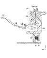
- FIG. 1 is a top view schematically showing a shift device 1 according to Embodiment 1.
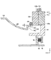
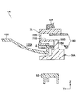
- FIG. FIG. 2 is a cross-sectional view schematically showing a cross section taken along line AA of FIG. It is sectional drawing when the operation knob 7 exists in a 2nd position.
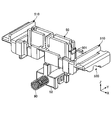
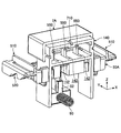
- 4 is a perspective view showing details of an example of an upper slider 50, a lower slider 52, and a spring 90.
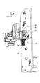
- FIG. 4 is a perspective view showing details of an example of a substrate 70 and a sliding contact 54.
- FIG. It is explanatory drawing of the effect by Example 1.
- FIG. It is explanatory drawing of 1 A of shift apparatuses by Example 2.
- FIG. It is explanatory drawing of 1 A of shift apparatuses by Example 2.
- FIG. It is a perspective view which shows the mechanism which supports the operation knob 7A by Example 2 so that sliding is possible.
- FIG. 1 is a top view schematically showing a shift device 1 according to the first embodiment.
- FIG. 2 is a cross-sectional view schematically showing a cross section taken along line AA in FIG.
- three orthogonal axes X, Y, and Z are defined.
- the Y axis corresponds to the displacement direction (slide direction) of the operation knob described later.
- the Y axis extends substantially in the horizontal plane, and the Z axis corresponds to the vertical direction.
- the Z axis may not be parallel to the direction of gravity.
- the shift device 1 is a push-type shift device for changing the gear ratio, and is operated by a user.
- the gear ratio to be switched is the gear ratio of the transmission (transmission), and the type of transmission is arbitrary.
- the shift device 1 is mounted on a mobile body having a transmission, such as a vehicle or an aircraft.
- the gear ratio for example, in a vehicle, the shift device 1 may be used for a shift-by-wire shift operation.
- the shift device 1 includes a case body 10 and operation knobs 2, 3, and 7.
- the case body 10 is made of, for example, resin.
- the case body 10 is fixed to the moving body.
- the case body 10 may be formed of a plurality of members.
- the case body 10 includes a panel member 12 that forms the upper surface of the shift device 1.
- the case body 10 has a recess 120 that is recessed downward on the upper surface.
- the recess 120 is deeper toward the negative side in the Y direction (an example of the side from the first position toward the second position) than the basic surface 122 of the panel member 12 as it goes toward the negative side in the Y direction. Is formed.
- the recess 120 extends in the X direction by a length corresponding to the length of the operation knob 7 in the X direction.
- the recess 120 has a wall 130 as shown in FIG.
- the wall portion 130 functions as a defense wall against foreign matter.
- the wall portion 130 rises upward in the Z direction and the upper side in the Z direction defines an opening 126 (described later).
- the wall 130 preferably extends in the X direction so as to cover the entire X direction of the operation knob 7. That is, the relationship between the wall 130 and the operation knob 7 shown in FIG. 2 (the same applies to the relationship in FIG. 3 described later) is preferably realized at an arbitrary position in the X direction of the operation knob 7.
- the wall portion 130 includes a first portion 132 that rises upward and a second portion 134.
- the second part 134 extends from the upper end of the first part 132 to the Y direction negative side.
- the case main body 10 has an opening 126 that opens in the Y direction at the end on the Y direction negative side in the recess 120.
- the opening 126 is formed by a vertical difference between the portion 124 of the panel member 12 extending on the Y direction negative side with respect to the recess 120 and the surface of the recess 120.
- the part 124 of the panel member 12 defines an opening 126 on the lower side
- the wall 130 of the recess 120 defines the opening 126 on the upper side.
- the opening 126 includes an end 124a on the Y direction positive side of the portion 124, an end 120a on the Y direction negative side of the recess 120 (an end 120a on the Y direction negative side of the wall 130), and the like. Formed between.
- the portion 124 preferably extends within a range that does not overlap with the concave portion 120 in a top view (view viewed in the Z direction) due to the ease of assembly.
- the operation knobs 2, 3, and 7 are members operated by the user.
- the operation knobs 2 and 3 are, for example, members that are operated in the up-down direction or an oblique direction that is slightly inclined with respect to the up-down direction, and the operation knob 7 is a slide-type operation knob that is operated in the Y direction. is there. In the example shown in FIG. 1, the operation knob 7 is disposed closer to the operation knob 3 than the operation knob 2 in the Y direction. In a modification, either one or both of the operation knobs 2 and 3 may be omitted, or another operation knob may be added.
- FIG. 3 is a sectional view equivalent to FIG. 2 showing a state when the operation knob 7 is in the second position.
- FIG. 2 shows a state when the operation knob 7 is in the first position.
- the operation knob 7 is provided in the opening 126.
- the operation knob 7 can be displaced in the Y direction between a first position shown in FIG. 2 and a second position shown in FIG. As shown in FIGS. 2 and 3, the second position is on the Y direction negative side with respect to the first position.
- the distance between the first position and the second position in the Y direction corresponds to the operation stroke of the operation knob 7.
- “exposed from the opening 126” means a straight line connecting the entrance surface of the opening 126 (that is, the end 124a on the Y direction positive side of the portion 124 and the end 120a on the Y direction negative side of the recess 120).
- the surface determined by the X axis) means that a part of the operation knob 7 protrudes to the Y direction positive side.
- the portion 124 preferably exposes the upper portion of the operation knob 7 in the first position. Thereby, the operation (see arrow R1) by the user is facilitated, and the operability is improved.
- the operation knob 7 preferably has two members 7a and 7b (hereinafter referred to as “first operation knob 7a” and “second operation knob 7b”) as shown in FIG.
- the second operation knob 7b is attached to the first operation knob 7a and extends to the Y direction positive side with respect to the first operation knob 7a.
- the second operation knob 7b faces the concave portion 120 (more precisely, the wall portion 130 of the concave portion 120) in the Z direction, as shown in FIG.
- the knob 7a does not face the recess 120 in the Z direction. Thereby, assembly property improves.
- the panel member 12 is assembled to the knob assembly in the vertical direction downward (see arrow R2 in FIG. 2) ( After that, the second operation knob 7b can be assembled to the knob assembly, and the assemblability is improved.
- the first operation knob 7 a does not completely face the recess 120 in the Z direction when the operation knob 7 is in the first position, but the first operation knob 7 a is not recessed. It may be opposed to 120 in the Z direction. That is, the first operation knob 7a is moved to the second position shown in FIG. 3, and the panel member 12 is assembled after the first operation knob 7a is not opposed to the recess 120 in the Z direction. Improves as well.
- the knob assembly refers to a state in which the first operation knob 7a is assembled to an upper slider 50, a lower slider 52, and the like which will be described later with reference to FIGS.
- the second operation knob 7b forms a pressing operation surface 720 whose positive surface in the Y direction is pressed by the user.
- the pressing operation surface 720 extends in the vertical direction and the X direction.
- the pressing operation surface 720 may be processed to improve operability and the like.
- the pressing operation surface 720 may be textured or plated to improve design. In this case, it is only necessary to process the second operation knob 7b (particularly the second operation knob 7b, which is a separate component smaller than the first operation knob 7a), which is separate from the first operation knob 7a. It becomes easy.
- the lower surface of the second operation knob 7b faces the upper surface of the second portion 134 of the wall 130 in the vertical direction with a predetermined gap ⁇ .
- the predetermined gap ⁇ is preferably the same at any position in the facing range, and does not change depending on the position of the operation knob 7 (an arbitrary position between the first position and the second position). . That is, the lower surface of the second operation knob 7b extends into a surface that is offset from the upper surface of the second portion 134 of the wall 130 by the gap ⁇ . Therefore, the operation knob 7 can be displaced in the Y direction between the first position shown in FIG. 2 and the second position shown in FIG. 3 without sliding with respect to the recess 120.
- the predetermined gap ⁇ corresponds to the minimum gap between the lower surface of the second operation knob 7 b and the upper surface of the second portion 134 of the wall 130.
- the “minimum gap” corresponds to the minimum distance in an arbitrary direction.
- the predetermined gap ⁇ is a minute gap that realizes a function (described later) as a defensive wall against foreign substances by the wall 130, and may be, for example, 0.1 to 0.3 mm, preferably 0.2 mm. It may be.
- the wall 130 and the lower surface of the operation knob 7 are located at the first position shown in FIG. 2 and the second position shown in FIG. 3. Even if it is in any position between, it opposes in the up-down direction. More specifically, the lower surface of the second operation knob 7b is a wall portion even when the operation knob 7 is in any position between the first position shown in FIG. 2 and the second position shown in FIG. It opposes the upper surface of 130 2nd site
- the gap is the same means a gap when the operation knob 7 is at the first position and a gap when the operation knob 7 is at the second position, which affects the function of the wall 130 as a defensive wall against foreign matter. Meaning there is no significant difference.
- the upper slider 50 is integrally connected to the lower side of the operation knob 7 as schematically shown in FIGS.
- the operation knob 7 is connected to the upper slider 50 by snap fitting.
- the lower slider 52 is connected to the upper slider 50 so that it cannot be displaced in the Y direction.
- the upper slider 50 is connected to the lower slider 52 by pin fitting in the vertical direction.
- the lower slider 52 is biased to the Y direction positive side from the spring 90.
- the other end of the spring 90 (the end that is not on the lower slider 52 side) is supported by the case body 10.
- the lower slider 52 includes a sliding contact 54 (see FIG. 5) that is electrically connected to a contact 72 (see FIG. 5) on the substrate 70.
- FIG. 4 is a perspective view showing details of an example of the upper slider 50, the lower slider 52, and the spring 90.
- FIG. 5 is a perspective view showing details of an example of the substrate 70 and the sliding contact 54.
- FIG. 5 shows the upper slider 50, the lower slider 52, and the spring 90 together.
- the upper slider 50 has a claw portion 501 for snap fitting with the operation knob 7, and slide guide portions 510 are provided on both sides in the X direction.
- the slide guide portion 510 is sandwiched from the upper and lower sides by the case body 10 (not shown). Therefore, the upper slider 50 is supported by the case body 10 through the slide guide portion 510 in such a manner that only displacement in the Y direction is allowed.
- the upper slider 50 includes cam portions 520 for creating a feeling of operation on both sides in the X direction (only one side is visible in FIG. 4). An actuator (not shown) is engaged with the cam portion 520 in the vertical direction.
- the sliding terminal portion 80 is held on the lower slider 52, and the sliding contact 54 provided on the lower side of the sliding terminal portion 80 contacts the substrate 70.
- the sliding contact 54 slides in the Y direction on the substrate 70, and the electrical connection state with the contact 72 on the substrate 70 changes.
- the operation knob 7 reaches the second position, the sliding contact 54 is electrically connected to the contact 72 on the substrate 70 (that is, generates an operation signal).
- a plurality of sets of the sliding contact 54 and the contact 72 may be provided, and an operation signal may be generated based on the principle of majority decision.
- the contact 72 of the substrate 70 forms an example of a contact portion that generates an operation signal based on the displacement of the operation knob 7 to the second position.
- a rubber dome type switch or the like may be used as a contact portion that generates an operation signal based on the displacement of the operation knob 7 to the second position.
- the rubber dome type switch may be arranged in a manner of being displaced in the Y direction.
- the upper slider 50 and the lower slider 52 are provided using the space below the operation knob 7, for example, the upper slider 50 is relatively large (for example, larger than the operation knob 7). Can be formed.
- the operation knob 3 when the operation knob 3 is provided adjacent to the operation knob 7 on the negative side in the Y direction, the operation knob 3 is compared with the case where the operation knob 3 is not provided. On the negative side in the Y direction with respect to 7, the restriction on the space for arranging the mechanism for the operation knob 7 becomes larger.
- the operation knob 7 is provided in the vicinity of the end on the Y direction negative side of the recess 120, and therefore the space below the recess 120 is more constrained than the operation knob 7 on the Y direction negative side. It tends to be less. From this point of view, the upper slider 50 can be enlarged by forming the slide guide portion 510 and the like of the upper slider 50 using the space below the recess 120.
- the stability of displacement during the slide operation can be enhanced. Further, it is possible to easily ensure rigidity that does not deform even with respect to an external force (such as input via a spring) input via the cam portion 520 or the like.
- the wall 130 is not provided.
- the highly viscous liquid 101 enters the recess 62, the liquid 101 flows into the space between the slide type operation knob 61 and the panel member 60 (see arrow 63), and the operation knob 61 is fixed. There is a risk of getting stuck.
- the liquid 101 when the highly viscous liquid 101 enters the recess 120, the liquid 101 similarly moves downward due to gravity.
- the liquid 102 as shown by the liquid 102, it is blocked by the first portion 132 of the wall 130. That is, due to the blocking function by the first portion 132 of the wall portion 130, it becomes difficult for liquid to enter between the operation knob 7 and the wall portion 130, which is a disadvantage that occurs in the comparative example shown in FIG. 7 sticking) can be reduced.
- a wall 65 for blocking liquid is simply provided in front of the operation knob 61 (positive side in the Y direction).
- the operation knob 61 at the operation position (in a state of being slid to the negative side in the Y direction) is indicated by a solid line, and the operation knob 61 at the non-operation position is indicated by a broken line.
- the wall 65 can function in the same manner as the first portion 132 of the wall portion 130 according to the first embodiment, it is possible to reduce inconvenience caused by the liquid flowing between the sliding operation knob 61 and the panel member 60. it can.
- FIG. 1 the comparative example shown in FIG.
- the shift device 1A according to the second embodiment is different from the shift device 1 according to the first embodiment described above in that the operation knob 7 and the recess 120 are replaced with the operation knob 7A and the recess 120A, and the operation knob 7A is slidably supported.
- Different mechanism Different parts will be mainly described, and components that may be substantially the same are denoted by the same reference numerals and description thereof will be omitted.
- FIG. 10 is a schematic cross-sectional view of the shift device 1A when the operation knob 7A is in the first position
- FIG. 11 is a schematic cross-section of the shift device 1A when the operation knob 7A is in the second position.
- FIG. FIG. 12 is a perspective view showing a mechanism for slidably supporting the operation knob 7A. 10 and 11, illustration of the substrate 70, the spring 90, and the like is omitted.
- the operation knob 7A can be displaced in the Y direction between the first position shown in FIG. 10 and the second position shown in FIG. As shown in FIG. 12, the operation knob 7A includes a portion 710 that contacts the protrusion 550 of the upper slider 50A in the Y direction.
- the part 710 protrudes from the surface opposite to the pressing operation surface 720 pressed by the user to the Y direction negative side. Therefore, the part 710 is a part that does not affect the appearance of the operation knob 7A.
- the operation knob 7A is supported by a slide support member 140 forming the case body 10 so as to be slidable in the Y direction.
- the slide support member 140 has a long hole 142 that is long in the Y direction through which the protrusion 550 of the upper slider 50A is inserted. Therefore, the upper slider 50A can be displaced in the Y direction integrally with the operation knob 7A without interfering with the slide support member 140.
- the upper slider 50A has a slide guide portion 510, a cam portion 520, and the like, similar to the upper slider 50 according to the first embodiment.
- the recess 120A is different from the recess 120 according to the first embodiment described above in that the wall 130 is replaced with a wall 130A.
- the wall portion 130A is different from the wall portion 130 according to the first embodiment described above in that only the first portion 132 of the first portion 132 and the second portion 134 is provided.
- the wall portion 130 ⁇ / b> A functions as a defense wall against foreign matter, like the wall portion 130 according to the first embodiment described above.
- the upper surface of the wall portion 130A faces the lower surface of the operation knob 7A in the vertical direction with a predetermined gap ⁇ .
- the predetermined gap ⁇ preferably does not change depending on the position of the operation knob 7A (an arbitrary position between the first position and the second position). Therefore, the operation knob 7A can be displaced in the Y direction between the first position shown in FIG. 10 and the second position shown in FIG.
- the wall 130A and the lower surface of the operation knob 7A have a first position shown in FIG. 10 and a second position shown in FIG. Even if it is in any position between, it opposes in the up-down direction. More specifically, the lower surface of the operation knob 7A is formed on the wall portion 130A regardless of whether the operation knob 7A is at a position between the first position shown in FIG. 10 and the second position shown in FIG. Opposite the upper surface in the vertical direction. As a result, the minimum gap between the lower surface of the operation knob 7A and the upper surface of the wall portion 130A is set so that the operation knob 7A is between the first position shown in FIG. 10 and the second position shown in FIG.
- the minimum gap is exactly the same regardless of whether the operation knob 7 is located between the first position shown in FIG. 10 and the second position shown in FIG. It is not necessary that they are substantially the same.
- the same effect as in the first embodiment can be obtained. That is, according to the second embodiment, due to the blocking function by the wall portion 130A, it becomes difficult for liquid to enter between the operation knob 7A and the wall portion 130A, which is a disadvantage caused in the comparative example shown in FIG. (Fixing of the operation knob 7A) can be reduced.
- the operation knob 7A and the wall portion 130A are operated when the operation knob 7A is operated (when displaced to the second position). In this case, the solid does not get caught between them, and the inconvenience (inconvenience that the operation knob 7A cannot be returned to the first position due to the solid being caught) in the comparative example shown in FIG. 7 can be reduced.
Landscapes
- Engineering & Computer Science (AREA)
- Physics & Mathematics (AREA)
- General Physics & Mathematics (AREA)
- Automation & Control Theory (AREA)
- Chemical & Material Sciences (AREA)
- Combustion & Propulsion (AREA)
- Transportation (AREA)
- Mechanical Engineering (AREA)
- Arrangement Or Mounting Of Control Devices For Change-Speed Gearing (AREA)
- Mechanical Control Devices (AREA)
Abstract
プッシュ式シフト装置は、上下方向とは異なる方向をスライド方向とし、第1位置と第2位置との間でスライド方向に変位可能であるスライド式の操作ノブと、上側の表面に下側に凹む凹部を形成し、凹部内にスライド方向に開口しかつ操作ノブの一部が露出する開口部を形成するケース本体と、操作ノブの変位に基づいて操作信号を生成する接点部とを備え、凹部は、上側に立ち上がりかつ上側に開口部を画成する壁部を有し、壁部と、操作ノブの下側の表面とは、操作ノブが第1位置と第2位置の間のいずれの位置にあるときでも、上下方向で対向し、壁部と操作ノブの下側の表面との間の隙間は、操作ノブが第1位置にあるときと第2位置にあるときとで、同じである。
Description
本開示は、プッシュ式シフト装置に関する。
シフトレバーに代えて、操作ノブ(プッシュボタン)を介したシフト操作入力に応じて変速比の切り替えを行うプッシュ式シフト装置が知られている。プッシュ式シフト装置では、ケース本体が凹部を形成し、凹部内に、上下方向とは異なる方向に変位可能な操作ノブ(以下、「スライド式の操作ノブ」と称する)が設けられる場合がある。
しかしながら、上記のような従来技術では、凹部内に落下等する異物に起因してスライド式の操作ノブの本来の操作性が損なわれる虞がある。例えば、粘性の高い液体が凹部に侵入すると液体がスライド式の操作ノブとパネルとの間に流れこんで固まってしまい、操作ノブが固着して動かなくなる虞がある。これに対して、単純に操作ノブの手前に、液体を塞き止めるための壁を設けるだけでは、操作ノブのスライド操作時に壁とノブとの間にスライド方向の隙間ができ、該隙間にお菓子などの大きめの固体が挟まり易くなる。操作ノブのスライド操作時に壁とノブとの間に固体が挟まると、操作ノブが初期位置に戻れないという問題が生じる。
そこで、1つの側面では、本発明は、凹部内に異物が落下等してもスライド式の操作ノブの本来の操作性を維持できる可能性を高めることを目的とする。
1つの側面では、上下方向とは異なる方向をスライド方向とし、第1位置と第2位置との間で前記スライド方向に変位可能であるスライド式の操作ノブと、
上側の表面に下側に凹む凹部を形成し、前記凹部内に前記スライド方向に開口しかつ前記操作ノブの一部が露出する開口部を形成するケース本体と、
前記操作ノブの前記第2位置への変位に基づいて操作信号を生成する接点部とを備え、
前記凹部は、上側に立ち上がりかつ上側に前記開口部を画成する壁部を有し、
前記壁部と、前記操作ノブの下側の表面とは、前記操作ノブが前記第1位置と前記第2位置の間のいずれの位置にあるときでも、上下方向で対向し、前記壁部と前記操作ノブの下側の表面との間の隙間は、前記操作ノブが前記第1位置にあるときと前記第2位置にあるときとで、同じである、プッシュ式シフト装置が提供される。
上側の表面に下側に凹む凹部を形成し、前記凹部内に前記スライド方向に開口しかつ前記操作ノブの一部が露出する開口部を形成するケース本体と、
前記操作ノブの前記第2位置への変位に基づいて操作信号を生成する接点部とを備え、
前記凹部は、上側に立ち上がりかつ上側に前記開口部を画成する壁部を有し、
前記壁部と、前記操作ノブの下側の表面とは、前記操作ノブが前記第1位置と前記第2位置の間のいずれの位置にあるときでも、上下方向で対向し、前記壁部と前記操作ノブの下側の表面との間の隙間は、前記操作ノブが前記第1位置にあるときと前記第2位置にあるときとで、同じである、プッシュ式シフト装置が提供される。
1つの側面では、本発明によれば、凹部内に異物が落下等してもスライド式の操作ノブの本来の操作性を維持できる可能性を高めることができる。
以下、添付図面を参照しながら各実施例について詳細に説明する。
[実施例1]
図1は、実施例1によるシフト装置1を概略的に示す上面図である。図2は、図1のラインA-Aに沿った断面を概略的に示す断面図である。図1には、直交する3軸X,Y,Zが定義されている。Y軸は、後述の操作ノブの変位方向(スライド方向)に対応する。尚、シフト装置1の搭載状態では、Y軸は、略水平面内に延在し、Z軸は、上下方向に対応する。但し、シフト装置1の搭載状態では、Z軸は、重力方向に平行ではない場合もありうる。
図1は、実施例1によるシフト装置1を概略的に示す上面図である。図2は、図1のラインA-Aに沿った断面を概略的に示す断面図である。図1には、直交する3軸X,Y,Zが定義されている。Y軸は、後述の操作ノブの変位方向(スライド方向)に対応する。尚、シフト装置1の搭載状態では、Y軸は、略水平面内に延在し、Z軸は、上下方向に対応する。但し、シフト装置1の搭載状態では、Z軸は、重力方向に平行ではない場合もありうる。
シフト装置1は、変速比の切り替え操作用のプッシュ式シフト装置であり、ユーザにより操作される。切り替え対象の変速比は、トランスミッション(変速機)の変速比であり、トランスミッションの形式は任意である。シフト装置1は、トランスミッションを有する移動体、例えば車両や航空機などに搭載される。変速比は、例えば、車両において、シフト装置1は、シフトバイワイヤ式のシフト操作に利用されてもよい。
シフト装置1は、ケース本体10と、操作ノブ2,3,7とを含む。
ケース本体10は、例えば樹脂等で形成される。ケース本体10は、移動体に固定される。ケース本体10は、複数の部材により形成されてよい。ケース本体10は、シフト装置1の上面を形成するパネル部材12を含む。
ケース本体10は、上側の表面に下側に凹む凹部120を形成する。凹部120は、例えば図2に示すように、パネル部材12の基本表面122よりもY方向の負側(第1位置から第2位置に向かう側の一例)に、Y方向負側に向かうほど深くなる態様で形成される。凹部120は、図1に示すように、X方向では、操作ノブ7のX方向の長さに対応した長さで延在する。
凹部120は、図2に示すように、壁部130を有する。壁部130は、後述するように、異物に対する防御壁として機能する。壁部130は、Z方向で上側に立ち上がりかつZ方向で上側が開口部126(後述)を画成する。壁部130は、好ましくは、操作ノブ7のX方向の全体をカバーする態様でX方向に延在する。即ち、図2に示す壁部130と操作ノブ7との関係(後出の図3の関係も同様)は、好ましくは、操作ノブ7のX方向の任意の位置で実現される。実施例1では、一例として、壁部130は、上側に立ち上がる第1部位132と、第2部位134とを含む。第2部位134は、第1部位132における上側の端部から、Y方向負側に延在する。
また、ケース本体10は、図2に示すように、凹部120内におけるY方向負側の端部に、Y方向に開口する開口部126を形成する。図2に示す例では、開口部126は、凹部120よりもY方向負側に延在するパネル部材12の部位124と、凹部120の表面との間の上下方向の差によって形成される。具体的には、パネル部材12の部位124は、下側に開口部126を画成し、凹部120の壁部130は、上側に開口部126を画成する。より具体的には、開口部126は、部位124のY方向正側の端部124aと、凹部120のY方向負側の端部120a(壁部130のY方向負側の端部120a)との間に形成される。尚、部位124は、好ましくは、組み付け性の関係で、凹部120とは上面視(Z方向に視たビュー)で重ならない範囲内に延在する。
操作ノブ2,3,7は、ユーザにより操作される部材である。操作ノブ2,3は、例えば上下方向又は上下方向に対して若干傾斜した斜め方向に操作される部材であり、操作ノブ7は、スライド式の操作ノブであり、Y方向に操作される部材である。尚、図1に示す例では、操作ノブ7は、Y方向で操作ノブ2よりも操作ノブ3の近くに配置される。変形例では、操作ノブ2,3のいずれか一方又は双方が省略されてもよいし、他の操作ノブが追加されてもよい。
ここで、図2及び図3を参照して、操作ノブ7を更に説明する。
図3は、操作ノブ7が第2位置にあるときの状態を示す図2と同等の断面図である。尚、図2は、操作ノブ7が第1位置にあるときの状態を示す。
操作ノブ7は、開口部126に設けられる。操作ノブ7は、図2に示す第1位置と図3に示す第2位置との間でY方向に変位可能である。第2位置は、図2及び図3に示すように、第1位置よりもY方向負側である。Y方向で第1位置と第2位置との間の距離は、操作ノブ7の操作ストロークに対応する。操作ノブ7は、第1位置にあるとき及び第2位置にあるときにY方向の正側(第2位置から第1位置に向かう側の一例)の端部が開口部126から露出する。尚、「開口部126から露出する」とは、開口部126の入口面(即ち、部位124のY方向正側の端部124aと凹部120のY方向負側の端部120aとを結ぶ直線と、X軸とにより定まる面)からY方向正側に操作ノブ7の一部が出ていることを意味する。尚、この場合、部位124は、好ましくは、第1位置にある操作ノブ7の上部を露出させる。これにより、ユーザによる操作(矢印R1参照)が容易となり、操作性が向上する。
操作ノブ7は、好ましくは、図2に示すように、2部材7a,7b(以下、「第1操作ノブ7a」及び「第2操作ノブ7b」と称する)を有する。第2操作ノブ7bは、第1操作ノブ7aに取り付けられ、第1操作ノブ7aよりもY方向正側に延在する。操作ノブ7が第1位置にあるとき、第2操作ノブ7bは、図2に示すように、凹部120(正確には、凹部120の壁部130)にZ方向で対向する一方、第1操作ノブ7aは、凹部120にZ方向で対向しない。これにより、組み付け性が向上する。具体的には、第1操作ノブ7aを含むノブアセンブリに第2操作ノブ7bを取り付ける前に、パネル部材12を、上下方向で下向き(図2の矢印R2参照)にノブアセンブリに対して組み付け(被せる態様で組み付け)、その後、第2操作ノブ7bをノブアセンブリに組み付けることができ、組み付け性が良好となる。尚、図2に示す例では、第1操作ノブ7aは、操作ノブ7が第1位置にあるときに完全に凹部120にZ方向で対向していないが、第1操作ノブ7aの部位が凹部120にZ方向で対向していてもよい。つまり、第1操作ノブ7aを図3に示す第2位置まで移動して、第1操作ノブ7aが凹部120にZ方向で対向していない状態にしてからパネル部材12を組み付けることにより、組み付け性が同様に向上する。対照的に、ノブアセンブリに第2操作ノブ7bを取り付けた状態では、パネル部材12を、下向き(図2の矢印R2参照)に操作ノブ7に対して組み付けようとすると、図2または図3のいずれの状態でもパネル部材12の凹部120が第2操作ノブ7bに干渉して組み付けが不能又は困難となる。尚、ノブアセンブリとは、例えば、図4及び図5を参照して後述する上側スライダ50や下側スライダ52等に第1操作ノブ7aが組み付けられた状態を指す。
第2操作ノブ7bは、Y方向の正側の表面が、ユーザにより押圧操作される押圧操作面720を形成する。押圧操作面720は、上下方向かつX方向に延在する。押圧操作面720には、操作性等を高めるための、加工がなされてよい。例えば、押圧操作面720には、シボ加工されてもよく、デザイン性向上のためにめっき加工されてもよい。この場合、第1操作ノブ7aとは別体である第2操作ノブ7b(特に第1操作ノブ7aよりも小さな別部品である第2操作ノブ7b)を加工するだけでよいので、部品加工が容易となる。
第2操作ノブ7bの下側の表面は、壁部130の第2部位134の上側表面と所定の隙間Δを介して上下方向に対向する。尚、所定の隙間Δは、好ましくは、対向範囲内のどの位置でも同じであり、また、操作ノブ7の位置(第1位置と第2位置の間の任意の位置)に依存して変化しない。即ち、第2操作ノブ7bの下側の表面は、壁部130の第2部位134の上側表面を上側に隙間Δだけオフセットした表面内に延在する。従って、操作ノブ7は、凹部120に対して摺動せずに、図2に示す第1位置と図3に示す第2位置との間でY方向に変位可能である。
尚、所定の隙間Δは、第2操作ノブ7bの下側の表面と壁部130の第2部位134の上側表面との間の最小の隙間に対応する。「最小の隙間」とは、任意の方向の最小の距離に対応する。所定の隙間Δは、壁部130による異物に対する防御壁としての機能(後述)が実現されるような微小な隙間であり、例えば0.1~0.3mmであってよく、好ましくは0.2mmであってよい。
実施例1では、図2及び図3に示すように、壁部130と、操作ノブ7の下側の表面とは、操作ノブ7が図2に示す第1位置と図3に示す第2位置の間のいずれの位置にあるときでも、上下方向で対向する。より具体的には、第2操作ノブ7bの下側の表面は、操作ノブ7が図2に示す第1位置と図3に示す第2位置の間のいずれの位置にあるときでも、壁部130の第2部位134の上側表面と上下方向で対向する。これにより、第2操作ノブ7bの下側の表面と壁部130の第2部位134の上側表面との間の最小の隙間を、操作ノブ7が図2に示す第1位置と図3に示す第2位置の間のいずれの位置にあるときでも、同じ(図2及び図3に示す例では、隙間Δ)にすることができる。但し、最小の隙間は、操作ノブ7が図2に示す第1位置と図3に示す第2位置の間のいずれの位置にあるときでも、厳密に同じである必要はなく、略同じであればよい。つまり、「隙間が同じ」とは、操作ノブ7が第1位置にあるときの隙間と第2位置にあるときの隙間とで、壁部130による異物に対する防御壁としての機能に影響するような有意な差異がないことを意味する。
操作ノブ7の下側には、図2及び図3に模式的に示すように、上側スライダ50が一体に接続される。例えば、操作ノブ7は、上側スライダ50とスナップ嵌合により接続される。また、上側スライダ50には、下側スライダ52がY方向に変位不能に接続される。例えば、上側スライダ50は、下側スライダ52と上下方向のピン嵌合により接続される。下側スライダ52は、バネ90よりY方向正側に付勢される。尚、バネ90の他端(下側スライダ52側でない端部)は、ケース本体10に支持される。下側スライダ52は、基板70上の接点72(図5参照)と電気的に接続される摺動接点54(図5参照)を備える。
図4は、上側スライダ50、下側スライダ52及びバネ90の一例の詳細を示す斜視図である。図5は、基板70及び摺動接点54の一例の詳細を示す斜視図である。図5には、上側スライダ50、下側スライダ52及びバネ90が併せて示される。
図4に示す例では、上側スライダ50は、操作ノブ7とのスナップ嵌合用の爪部501を有し、X方向の両側にスライドガイド部510が設けられる。スライドガイド部510は、ケース本体10により上下両側から挟持される(図示せず)。従って、上側スライダ50は、スライドガイド部510を介して、Y方向の変位のみが許容される態様でケース本体10に支持される。また、上側スライダ50は、X方向の両側に(図4では一方の側のみが可視)、操作感を作出するためのカム部520を備える。カム部520には、図示しないアクチュエータが上下方向に係合する。
図5に示す例では、下側スライダ52には、摺動端子部80が保持され、摺動端子部80の下側に設けられる摺動接点54が基板70に接触する。操作ノブ7と共に下側スライダ52がY方向に変位すると、摺動接点54が基板70上をY方向に摺動し、基板70上の接点72との電気的な接続状態が変化する。具体的には、操作ノブ7が第2位置に至ると、摺動接点54が基板70上の接点72と電気的に導通する(即ち操作信号を生成する)。尚、摺動接点54と接点72は複数組設けられ、多数決の原理に基づいて、操作信号が生成されてもよい。このようにして、基板70の接点72は、操作ノブ7の第2位置への変位に基づいて操作信号を生成する接点部の一例を形成する。尚、変形例では、操作ノブ7の第2位置への変位に基づいて操作信号を生成する接点部としては、ラバードーム式のスイッチ等が使用されてもよい。例えば、ラバードーム式のスイッチの場合は、ラバードーム式のスイッチは、Y方向に変位する態様で配置されてよい。
このように実施例1では、操作ノブ7の下側のスペースを利用して上側スライダ50及び下側スライダ52が設けられるので、例えば上側スライダ50を比較的大型(例えば操作ノブ7よりも大型)に形成できる。
より具体的には、実施例1のように、操作ノブ7に対してY方向負側に隣接して操作ノブ3が設けられる場合は、操作ノブ3が設けられない場合に比べて、操作ノブ7よりもY方向負側において、操作ノブ7のための機構を配置するスペースに対する制約が大きくなる。他方、実施例1においては、操作ノブ7は、凹部120のY方向負側の端部付近に設けられるので、凹部120の下方のスペースは、操作ノブ7よりもY方向負側よりも制約が少ない傾向となる。この観点から、凹部120の下方のスペースを利用して、上側スライダ50のスライドガイド部510等を形成することで、上側スライダ50の大型化が可能となる。
従って、上側スライダ50の大型化として、例えばX方向の両側にスライドガイド部510を設けることで、スライド操作時の変位の安定性を高めることができる。また、カム部520等を介して入力される外力(ばねを介した入力等)に対しても変形しないような剛性を容易に確保できる。
次に、比較例を示す図6及び図7と、図8及び図9を参照して、実施例1の効果(壁部130による異物に対する防御壁としての機能)について説明する。
図6に示す比較例では、壁部130が設けられていない。かかる比較例では、粘性の高い液体101が凹部62に侵入するとスライド式の操作ノブ61とパネル部材60との間(矢印63参照)に液体101が流れこんで固まってしまい、操作ノブ61が固着して動かなくなる虞がある。
これに対して、実施例1によれば、図8に示すように、粘性の高い液体101が凹部120に侵入すると、液体101は同様に重力によって下方に移動する。しかしながら、実施例1によれば、液体102で示すように、壁部130の第1部位132によって塞き止められる。即ち、壁部130の第1部位132による塞き止め機能に起因して、操作ノブ7と壁部130との間に液体が侵入し難くなり、図6に示す比較例で生じる不都合(操作ノブ7の固着)を低減できる。
図7に示す比較例では、単純に操作ノブ61の手前(Y方向の正側)に、液体を塞き止めるための壁65が設けられる。図7では、操作位置(Y方向の負側にスライド操作された状態)の操作ノブ61が実線で示され、非操作位置の操作ノブ61が破線で示されている。この場合、壁65は実施例1による壁部130の第1部位132と同様に機能できるので、スライド式の操作ノブ61とパネル部材60との間に液体が流れこむことに起因した不都合を低減できる。他方、図7に示す比較例では、操作ノブ61のスライド操作時に壁65と操作ノブ61との間にY方向の隙間Δ1ができ、お菓子などの大きめの固体104が挟まる可能性や、固体104がシフト装置1の内部に侵入する可能性がある。壁65と操作ノブ61との間に固体104が挟まると、操作ノブ61が初期位置に戻れないという問題が生じる。
これに対して、実施例1によれば、図9に示すように、操作ノブ7が第2位置にあるときでも壁部130と操作ノブ7との間に隙間ができることはない。従って、お菓子などの大きめの固体104が凹部120に落下等してきても、操作ノブ7の操作時(第2位置への変位時)に操作ノブ7と壁部130との間に固体が挟まることがなく、図7に示す比較例で生じる不都合(操作ノブ7が第1位置に戻れない不都合)を低減できる。
[実施例2]
実施例2によるシフト装置1Aは、上述した実施例1によるシフト装置1に対して、操作ノブ7及び凹部120が、操作ノブ7A及び凹部120Aで置換され、かつ、操作ノブ7Aをスライド可能に支持する機構が異なる。以下、異なる部分を中心に説明し、実質的に同一であってよい構成要素については、同一の参照符号を付して説明を省略する。
実施例2によるシフト装置1Aは、上述した実施例1によるシフト装置1に対して、操作ノブ7及び凹部120が、操作ノブ7A及び凹部120Aで置換され、かつ、操作ノブ7Aをスライド可能に支持する機構が異なる。以下、異なる部分を中心に説明し、実質的に同一であってよい構成要素については、同一の参照符号を付して説明を省略する。
図10は、操作ノブ7Aが第1位置にあるときのシフト装置1Aの概略的な断面図であり、図11は、操作ノブ7Aが第2位置にあるときのシフト装置1Aの概略的な断面図である。図12は、操作ノブ7Aをスライド可能に支持する機構を示す斜視図である。尚、図10及び図11では、基板70やバネ90等については図示が省略されている。
操作ノブ7Aは、図10に示す第1位置と図11に示す第2位置との間でY方向に変位可能である。操作ノブ7Aは、図12に示すように、上側スライダ50Aの突起550にY方向で当接する部位710を備える。尚、部位710は、ユーザにより押圧操作される押圧操作面720とは反対側の表面から、Y方向負側に突設される。従って、部位710は、操作ノブ7Aの外観に影響しない部位である。操作ノブ7Aは、ケース本体10を形成するスライド支持部材140に、Y方向にスライド可能に支持される。スライド支持部材140は、上側スライダ50Aの突起550が挿通されるY方向に長い長穴142を有する。従って、上側スライダ50Aは、スライド支持部材140に干渉することなく、操作ノブ7Aと一体にY方向に変位可能である。尚、上側スライダ50Aは、上述した実施例1による上側スライダ50と同様、図12に示すように、スライドガイド部510やカム部520等を有する。
凹部120Aは、図10及び図11に示すように、上述した実施例1による凹部120に対して、壁部130が壁部130Aで置換された点が異なる。壁部130Aは、上述した実施例1による壁部130に対して、第1部位132及び第2部位134のうちの、第1部位132だけしか備えていない点が異なる。
壁部130Aは、上述した実施例1による壁部130と同様、異物に対する防御壁として機能する。壁部130Aの上側表面は、操作ノブ7Aの下側の表面と所定の隙間Δを介して上下方向に対向する。尚、所定の隙間Δは、好ましくは、操作ノブ7Aの位置(第1位置と第2位置の間の任意の位置)に依存して変化しない。従って、操作ノブ7Aは、凹部120に対して摺動せずに、図10に示す第1位置と図11に示す第2位置との間でY方向に変位可能である。
実施例2では、図10及び図11に示すように、壁部130Aと、操作ノブ7Aの下側の表面とは、操作ノブ7Aが図10に示す第1位置と図11に示す第2位置の間のいずれの位置にあるときでも、上下方向で対向する。より具体的には、操作ノブ7Aの下側の表面は、操作ノブ7Aが図10に示す第1位置と図11に示す第2位置の間のいずれの位置にあるときでも、壁部130Aの上側表面と上下方向で対向する。これにより、操作ノブ7Aの下側の表面と壁部130Aの上側表面との間の最小の隙間を、操作ノブ7Aが図10に示す第1位置と図11に示す第2位置の間のいずれの位置にあるときでも、同じ(図10及び図11に示す例では、隙間Δ)にすることができる。但し、上述の実施例1の場合と同様、最小の隙間は、操作ノブ7が図10に示す第1位置と図11に示す第2位置の間のいずれの位置にあるときでも、厳密に同じである必要はなく、略同じであればよい。
従って、実施例2によっても、上述した実施例1と同様の効果を得ることができる。即ち、実施例2によれば、壁部130Aによる塞き止め機能に起因して、操作ノブ7Aと壁部130Aとの間に液体が侵入し難くなり、図6に示した比較例で生じる不都合(操作ノブ7Aの固着)を低減できる。また、実施例2によれば、お菓子などの大きめの固体が凹部120Aに落下等してきても、操作ノブ7Aの操作時(第2位置への変位時)に操作ノブ7Aと壁部130Aとの間に固体が挟まることがなく、図7に示した比較例で生じる不都合(固体が挟まって操作ノブ7Aが第1位置に戻れない不都合)を低減できる。
以上、各実施例について詳述したが、特定の実施例に限定されるものではなく、特許請求の範囲に記載された範囲内において、種々の変形及び変更が可能である。また、前述した実施例の構成要素を全部又は複数を組み合わせることも可能である。
本国際出願は2017年6月5日に出願された日本国特許出願2017-111203号に基づく優先権を主張するものであり、その全内容をここに援用する。
1 シフト装置
1A シフト装置
2 操作ノブ
3 操作ノブ
7 操作ノブ
7a 第1操作ノブ
7A 操作ノブ
7b 第2操作ノブ
10 ケース本体
12 パネル部材
50 上側スライダ
50A 上側スライダ
52 下側スライダ
54 摺動接点
70 基板
72 接点
80 摺動端子部
90 バネ
120 凹部
120a 端部
120A 凹部
122 基本表面
124 部位
124a 端部
126 開口部
130 壁部
130A 壁部
132 第1部位
134 第2部位
140 スライド支持部材
142 長穴
501 爪部
510 スライドガイド部
520 カム部
550 突起
710 部位
720 押圧操作面
1A シフト装置
2 操作ノブ
3 操作ノブ
7 操作ノブ
7a 第1操作ノブ
7A 操作ノブ
7b 第2操作ノブ
10 ケース本体
12 パネル部材
50 上側スライダ
50A 上側スライダ
52 下側スライダ
54 摺動接点
70 基板
72 接点
80 摺動端子部
90 バネ
120 凹部
120a 端部
120A 凹部
122 基本表面
124 部位
124a 端部
126 開口部
130 壁部
130A 壁部
132 第1部位
134 第2部位
140 スライド支持部材
142 長穴
501 爪部
510 スライドガイド部
520 カム部
550 突起
710 部位
720 押圧操作面
Claims (4)
- 上下方向とは異なる方向をスライド方向とし、第1位置と第2位置との間で前記スライド方向に変位可能であるスライド式の操作ノブと、
上側の表面に下側に凹む凹部を形成し、前記凹部内に前記スライド方向に開口しかつ前記操作ノブの一部が露出する開口部を形成するケース本体と、
前記操作ノブの前記第2位置への変位に基づいて操作信号を生成する接点部とを備え、
前記凹部は、上側に立ち上がりかつ上側に前記開口部を画成する壁部を有し、
前記壁部と、前記操作ノブの下側の表面とは、前記操作ノブが前記第1位置と前記第2位置の間のいずれの位置にあるときでも、上下方向で対向し、前記壁部と前記操作ノブの下側の表面との間の隙間は、前記操作ノブが前記第1位置にあるときと前記第2位置にあるときとで、同じである、プッシュ式シフト装置。 - 前記壁部は、上側に立ち上がる第1部位と、前記第1部位における上側の端部から、前記スライド方向で前記第1位置から前記第2位置に向かう側に延在する第2部位とを含み、
前記操作ノブの下側の表面と前記第2部位とが、前記操作ノブが前記第2位置にあるときの前記隙間を定める、請求項1に記載のプッシュ式シフト装置。 - 前記操作ノブは、第1操作ノブと、前記第1操作ノブに取り付けられ、前記第1操作ノブよりも前記スライド方向で前記第2位置から前記第1位置に向かう側に延在する第2操作ノブとを含み、
前記操作ノブが前記第2位置にあるときに、前記第1操作ノブ及び前記第2操作ノブのうちの、前記第2操作ノブのみが、前記壁部に上下方向で対向する、請求項1または請求項2に記載のプッシュ式シフト装置。 - 前記第2操作ノブは、前記スライド方向で前記第2位置から前記第1位置に向かう側の表面が、ユーザにより押圧操作される押圧操作面を形成する、請求項3に記載のプッシュ式シフト装置。
Priority Applications (2)
| Application Number | Priority Date | Filing Date | Title |
|---|---|---|---|
| CN201880031606.8A CN110621530B (zh) | 2017-06-05 | 2018-04-19 | 推压式换档装置 |
| JP2019523383A JP6716789B2 (ja) | 2017-06-05 | 2018-04-19 | プッシュ式シフト装置 |
Applications Claiming Priority (2)
| Application Number | Priority Date | Filing Date | Title |
|---|---|---|---|
| JP2017111203 | 2017-06-05 | ||
| JP2017-111203 | 2017-06-05 |
Publications (1)
| Publication Number | Publication Date |
|---|---|
| WO2018225399A1 true WO2018225399A1 (ja) | 2018-12-13 |
Family
ID=64566223
Family Applications (1)
| Application Number | Title | Priority Date | Filing Date |
|---|---|---|---|
| PCT/JP2018/016205 Ceased WO2018225399A1 (ja) | 2017-06-05 | 2018-04-19 | プッシュ式シフト装置 |
Country Status (3)
| Country | Link |
|---|---|
| JP (1) | JP6716789B2 (ja) |
| CN (1) | CN110621530B (ja) |
| WO (1) | WO2018225399A1 (ja) |
Citations (2)
| Publication number | Priority date | Publication date | Assignee | Title |
|---|---|---|---|---|
| JPH04340028A (ja) * | 1991-05-15 | 1992-11-26 | Matsushita Electric Ind Co Ltd | 電気採暖具のコントローラ |
| WO2013183513A1 (ja) * | 2012-06-08 | 2013-12-12 | 本田技研工業株式会社 | 車両用シフト装置 |
Family Cites Families (4)
| Publication number | Priority date | Publication date | Assignee | Title |
|---|---|---|---|---|
| KR101081052B1 (ko) * | 2009-12-01 | 2011-11-07 | 에스엘 주식회사 | 버튼식 변속노브를 구비한 변속레버 |
| DE102015012769A1 (de) * | 2014-10-29 | 2016-05-04 | U-Shin Ltd. | Schaltvorrichtung |
| JP6379014B2 (ja) * | 2014-11-13 | 2018-08-22 | 株式会社東海理化電機製作所 | シフト装置 |
| JP2017109510A (ja) * | 2015-12-14 | 2017-06-22 | トヨタ自動車株式会社 | シフトレバー装置 |
-
2018
- 2018-04-19 JP JP2019523383A patent/JP6716789B2/ja active Active
- 2018-04-19 CN CN201880031606.8A patent/CN110621530B/zh active Active
- 2018-04-19 WO PCT/JP2018/016205 patent/WO2018225399A1/ja not_active Ceased
Patent Citations (2)
| Publication number | Priority date | Publication date | Assignee | Title |
|---|---|---|---|---|
| JPH04340028A (ja) * | 1991-05-15 | 1992-11-26 | Matsushita Electric Ind Co Ltd | 電気採暖具のコントローラ |
| WO2013183513A1 (ja) * | 2012-06-08 | 2013-12-12 | 本田技研工業株式会社 | 車両用シフト装置 |
Also Published As
| Publication number | Publication date |
|---|---|
| CN110621530B (zh) | 2022-08-05 |
| JPWO2018225399A1 (ja) | 2020-01-23 |
| JP6716789B2 (ja) | 2020-07-01 |
| CN110621530A (zh) | 2019-12-27 |
Similar Documents
| Publication | Publication Date | Title |
|---|---|---|
| US20170114892A1 (en) | Shift lever device | |
| JP4973302B2 (ja) | 押しボタンスイッチ | |
| US20130220063A1 (en) | Switch device | |
| CN103140091A (zh) | 按键机构及其电子装置 | |
| EP2866241B1 (en) | Switching device for automotive user interface | |
| JP6716789B2 (ja) | プッシュ式シフト装置 | |
| JP2013030354A (ja) | スライドスイッチ、及び電子機器 | |
| JP6716790B2 (ja) | プッシュ式シフト装置 | |
| US20170004941A1 (en) | Rocker switch with movable light ducts | |
| CN101226838A (zh) | 开关 | |
| JP2011259059A (ja) | スライドユニット機構 | |
| JP2010113978A (ja) | 自動車室内用のプッシュ式スイッチ | |
| KR20100134239A (ko) | 스위치 장치 | |
| JP6604642B1 (ja) | ロッカースイッチのスライド操作変換用アダプタ。 | |
| JP4735452B2 (ja) | プッシュスイッチ | |
| JP6955431B2 (ja) | 連結構造 | |
| EP3431317B1 (en) | Shift device | |
| JP2007035402A (ja) | 電気装置の操作機構 | |
| EP4538092A1 (en) | Push-button switch for vehicles, in particular for vehicle door panels | |
| JP5056451B2 (ja) | 操作装置及びこれを備えたスイッチ装置 | |
| JP2007207563A (ja) | 電気装置の操作機構 | |
| KR100661981B1 (ko) | 전자기기용 노브설치구조 | |
| JP3184135U (ja) | スライドスイッチ | |
| JP2010003535A (ja) | プッシュスイッチ作動用つまみ | |
| WO2020183782A1 (ja) | 押釦および電子機器 |
Legal Events
| Date | Code | Title | Description |
|---|---|---|---|
| 121 | Ep: the epo has been informed by wipo that ep was designated in this application |
Ref document number: 18814475 Country of ref document: EP Kind code of ref document: A1 |
|
| ENP | Entry into the national phase |
Ref document number: 2019523383 Country of ref document: JP Kind code of ref document: A |
|
| NENP | Non-entry into the national phase |
Ref country code: DE |
|
| 122 | Ep: pct application non-entry in european phase |
Ref document number: 18814475 Country of ref document: EP Kind code of ref document: A1 |