WO2018225385A1 - 回転電機 - Google Patents
回転電機 Download PDFInfo
- Publication number
- WO2018225385A1 WO2018225385A1 PCT/JP2018/015845 JP2018015845W WO2018225385A1 WO 2018225385 A1 WO2018225385 A1 WO 2018225385A1 JP 2018015845 W JP2018015845 W JP 2018015845W WO 2018225385 A1 WO2018225385 A1 WO 2018225385A1
- Authority
- WO
- WIPO (PCT)
- Prior art keywords
- bobbin
- coil
- rotating electrical
- electrical machine
- winding
- Prior art date
- Legal status (The legal status is an assumption and is not a legal conclusion. Google has not performed a legal analysis and makes no representation as to the accuracy of the status listed.)
- Ceased
Links
Images



Classifications
-
- H—ELECTRICITY
- H02—GENERATION; CONVERSION OR DISTRIBUTION OF ELECTRIC POWER
- H02K—DYNAMO-ELECTRIC MACHINES
- H02K3/00—Details of windings
- H02K3/46—Fastening of windings on the stator or rotor structure
-
- H—ELECTRICITY
- H02—GENERATION; CONVERSION OR DISTRIBUTION OF ELECTRIC POWER
- H02K—DYNAMO-ELECTRIC MACHINES
- H02K3/00—Details of windings
- H02K3/46—Fastening of windings on the stator or rotor structure
- H02K3/52—Fastening salient pole windings or connections thereto
Definitions
- the present invention relates to a rotating electrical machine.
- motors used for electric power steering and the like are required to have a high output density.
- the strength of the magnetic field that can be generated by the coil is determined by the number of turns of the coil and the magnitude of the current that flows through the coil.
- the strength of the magnetic field has a strong effect on the output of the motor.
- Copper wire is being made thicker.
- the use of a thick wire can increase the current, while the motor manufacturing process has a problem of difficulty in processing the electric wire due to the thick wire.
- a thicker electric wire is difficult to bend or the like, and a concentrated winding coil affects the adhesion between the bobbin and the electric wire when the electric wire is wound around the bobbin.
- the bobbin of the concentrated winding coil has a large aspect ratio, but among these, the adhesion between the long side portion, which is substantially parallel to the rotation axis of the rotor, and the electric wire greatly affects the output density of the motor.
- the low adhesion is caused when the electric wire is wound around a substantially rectangular bobbin because the electric wire does not extend along the outline of the bobbin, and this phenomenon is referred to as winding swelling here. Suppressing this bulge is an inevitable problem in order to achieve both thickening of the concentrated winding coil and improvement of the output density.
- Patent Document 1 discloses a configuration in which the radius of curvature R2 on the coil winding end side is larger than the radius of curvature R1 on the coil winding start side in two curved portions constituting the bobbin end.
- a rotating electrical machine is a rotating electrical machine including a stator having a plurality of concentrated winding coils formed by winding a coil around a bobbin covering an iron core, the bobbin including a straight portion and the An end portion arranged in the longitudinal direction of the straight portion, and the end portion includes two curved portions that contact the straight portion and have a radius of curvature larger than half of the width of the bobbin, and a bending defining portion, At least a part of the bending defining portion is present at a position separated from the straight portion in the longitudinal direction by more than half the width of the bobbin.
- the coil bulge can be reduced.
- FIG. 7A is a plan view of the bobbin 3
- FIG. 7B is a bottom view of the bobbin 3.
- the figure which shows the problem which can occur when not suppressing the coil swelling The figure which shows the shape of the edge part 32 in the modification 3.
- the figure which shows the shape of the edge part 32 in the modification 5 The figure which shows the shape of 32 A of end parts in 2nd Embodiment
- the figure which shows the shape of the edge part 32B in 3rd Embodiment The figure which shows the shape of the bobbin 3 in 4th Embodiment
- the figure which shows the bobbin 3 in 5th Embodiment, and its manufacturing process The figure which shows the bobbin 3 in the modification of 5th Embodiment.
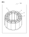
- FIG. 1 is a diagram illustrating an appearance of a stator.
- the electric motor 100 includes a stator 1 and a rotor (not shown).
- the stator 1 includes a plurality of iron cores 2, and coils 4 are intensively wound around the respective iron cores 2.
- the electric motor 100 employs concentrated winding as a winding form.
- the coil 4 When the coil 4 is energized, a magnetic field is generated, and a rotor (not shown) rotates.
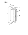
- FIG. 2 is a view showing the iron core 2 in a state after the coil 4 is wound
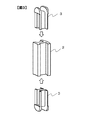
- FIG. 3 is a view showing the iron core 2 in a state before the coil 4 is wound.
- the direction of the arrow H shown in FIG. 2 is called the height direction or the longitudinal direction
- the direction of the arrow D is called the depth direction
- the direction of the arrow W is called the width direction.
- H, D, and W represent only directions and not dimensions, unidirectional arrows are used.
- Iron core 2 is composed of iron-based metal.
- the iron core 2 is manufactured, for example, by casting or machining. Further, the iron core 2 can be manufactured by stacking a plurality of thin steel plates punched into the cross-sectional shape of the iron core, or can be manufactured by pressing and compacting powdered metal.
- the iron core 2 is covered with a bobbin 3 formed of an insulating material such as resin for electrical insulation from the coil 4. As shown in FIG. 3, the bobbin 3 is inserted from both ends in the longitudinal direction of the iron core 2, and the coil 4 is wound after the bobbin 3 is inserted.
- the main material of the coil 4 is copper or aluminum.
- a combination of the iron core 2 and the bobbin 3 is fixed to the winding machine, and one end of the electric wire is fixed to the bobbin 3 or a jig around it.
- a method of winding the coil 4 around the bobbin 3 by rotating the iron core 2 and the bobbin 3 can be employed.
- the electric wire before being wound around the iron core 2 is also referred to as a coil 4.
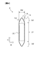
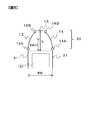
- FIG. 4 is a cross-sectional view of the bobbin 3. Since FIG. 4 is cut along a plane around which the coil 4 is wound, the top and bottom of FIG. 4 are the height direction, and the left and right of FIG. 4 are the width direction. When the bobbin 3 is conveniently divided according to its shape, the bobbin 3 is divided into an end portion 32, a straight portion 31, and an end portion 32 from the top in the longitudinal direction. As shown in FIG. 4, the width of the bobbin 3 is hereinafter referred to as a bobbin width BW.
- the outer shape of the straight portion 31 is a straight line and has a cavity into which the iron core 2 is inserted. However, since the straight portion 31 is formed by a combination of two members as shown in FIG. 3, a cut may exist in the middle in the longitudinal direction as shown in FIG. Although there are two end portions 32 in FIG. 4, since the shapes are the same, only the upper end portion 32 will be described here.
- the end portion 32 includes a first music portion 12, a second music portion 13, and a third music portion 14.
- the 1st music part 12 and the 3rd music part 14 are circular arcs which have the same curvature radius larger than BW.
- the second music part 13 is an arc having a smaller radius of curvature than the first music part 12 and the third music part 14.
- FIG. 5 is a diagram showing details of the end portion 32.
- the junction part of the linear part 31 and the edge part 32, the junction part of the 1st music part 12 and the 2nd music part 13, and the 2nd music part 13 and 3rd It is displayed with a gap between the joints of the curved portion 14.
- the broken line indicates the boundary between the straight line portion 31 and the end portion 32.
- both ends of the first curved portion 12 are referred to as a contact end 12A and a vertex end 12B
- the contact end 12A contacts the linear portion 31 and the vertex end 12B contacts the second curved portion 13.
- both ends of the third curved portion 14 are referred to as a contact end 14 ⁇ / b> A and a vertex end 14 ⁇ / b> B
- the contact end 14 ⁇ / b> A contacts the linear portion 31
- the vertex end 14 ⁇ / b> B contacts the second curved portion 13.
- the length from the boundary of the straight part 31 and the end part 32 to the top part of the 2nd music part 13 The direction distance L exceeds half of the bobbin width BW.
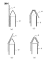
- FIG. 6 is a diagram illustrating a process of winding the coil 4 around the bobbin 3.
- the broken line represents the coil 4.
- the coil 4 is disposed along the straight portion 31 as shown in FIG.
- the coil 4 is lightly bent at the boundary between the straight portion 31 and the first curved portion 12 and is disposed along the first curved portion 12.
- the coil 4 is largely bent in the 2nd music part 13, as shown in FIG.6 (c).
- the 2nd music part 13 is a part which produces a big bending
- the 2nd music part 13 is also called a "bending definition part” below.
- the coil 4 is lightly bent at the boundary between the third curved portion 14 and the straight portion 31 as shown in FIG.
- winding the coil 4 in the direction shown in FIG. 6 is referred to as “winding the coil 4 around the bobbin 3 clockwise”.
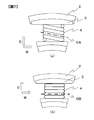
- FIG. 7A is a plan view of the bobbin 3, and FIG. 7B is a bottom view of the bobbin 3.
- FIG. 7 shows only one coil 4 for one layer.
- the coil 4 crosses the end of the bobbin 3 diagonally.
- the coil 4 crosses the end of the bobbin 3 in parallel as shown in FIG.
- the cut surfaces that cut the bobbin 3 along the coil 4 are referred to as a cut surface 6A and a cut surface 6B.
- the cross section obtained by cutting along the cut surface 6B is the cut surface shown in FIG.
- the lateral width of the cut surface is slightly larger than BW.
- the relationship between the radius of curvature and the lateral width is maintained. That is, the bulge is reduced at both the upper end and the lower end of the bobbin 3 as described below.
- the first characteristic configuration is a third curved portion 14 having a large curvature radius, which is disposed at a location where the coil 4 is wound from the end of the bobbin 3 toward the long side. Since the radius of curvature of the third curved portion 14 is large and is smoothly connected to the straight portion 31, the coil 4 to be wound starts to be wound around the straight portion 31 in a state where the winding bulge is small. If the radius of curvature of the third curved portion 14 is small, the coil 4 that has not been sufficiently bent is largely separated from the bobbin 3 and starts to be wound around the long side portion of the bobbin 3, thereby increasing the winding bulge. Cause.
- the second characteristic configuration is the first curved portion 12 having a large curvature radius, which is disposed at the portion where the coil 4 is wound from the straight portion 31 toward the end of the bobbin, that is, toward the second curved portion 13. is there. Since the radius of curvature of the first curved portion 12 is large and is smoothly connected to the straight portion 31 of the bobbin 3, the coil 4 to be wound is directed toward the tip of the bobbin 3 without being affected by strong bending. Thus, the volume of the coil 4 wound around the linear portion 31 that has been wound with gentle bending and has already passed is not increased.
- the coil 4 bent along the first bent portion 12 is affected by the abrupt bending process on both the front and rear sides of the bending base point.
- the coil 4 wound around the long side portion that passed through receives a force that moves in a direction away from the bobbin 3 and causes the winding swelling to increase.
- 3rd characteristic structure is the 2nd curved part 13 which is the bending
- FIG. Since the bending defining portion is provided near the tip of the bobbin 3, the coil 4 is strongly bent near the end of the bobbin 3. Therefore, it is not necessary to bend the coil 4 abruptly in the vicinity of the boundary between the straight portion 31 and the end portion 32, and an increase in winding bulge due to unbending can be prevented.
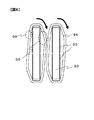
- FIG. 8 is a diagram illustrating a problem that may occur when the coil 94 is not restrained from being swollen.
- the bobbin 93 shown in FIG. 8 has a shape different from that of the bobbin 3 described above. In FIG. 8, only one layer of the coil 94 is wound around the bobbin 93 for simplification. In FIG. 8, the coil 94 is wound around the bobbin 93 clockwise as in FIG. 6. As shown in FIG. 8, the distance between the coil 94 and the iron core 92 due to the winding bulge is different before and after being wound.
- the bulge 99 of the coil 94 after reaching the end portion is larger than the bulge 98 of the coil 94 before reaching the end portion, and the distance between the coil 94 and the iron core 92 is further increased.
- the distance between the adjacent coils 94 is shortened by this winding bulge. Therefore, when the winding swelling is large, it is necessary to take measures such as separating the iron cores 92 from each other. Further, in order to minimize the influence of the bulging bulge, it is not sufficient to take measures against the bulging bulge maximum portion, that is, the bulging portion indicated by reference numeral 99 in FIG. is required.
- the electric motor 100 includes a stator 1 having a plurality of concentrated winding coils formed by winding a coil 4 around a bobbin 3 covering an iron core 2.
- the bobbin 3 includes a straight part 31 and an end part 32 arranged in the longitudinal direction of the straight part 31.
- the end portion 32 includes two curved portions that are in contact with the straight portion 31 and have a radius of curvature larger than half of the bobbin width BW, that is, the first curved portion 12 and the third curved portion 14.
- the end portion 32 further includes a bending defining portion, for example, the second curved portion 13, which exists away from the straight line portion 31 in the longitudinal direction more than half of the bobbin width BW. Therefore, the winding swelling of the coil 4 can be reduced.
- the second music part 13 has an arc shape having a smaller radius of curvature than the first music part 12 and the third music part 14.
- the 1st music part 12 and the 3rd music part 14 have the same curvature radius.
- the end 32 is symmetrical. Therefore, not only when the coil 4 is wound around the bobbin 3 clockwise as shown in FIG. 6, but also when the coil 4 is wound around the bobbin 3 counterclockwise, the bulging can be suppressed similarly.
- the coil 4 is wound around the bobbin 3 clockwise or counterclockwise by the salient pole in the direction of viewing the stator salient pole from the rotating shaft side of the rotor.
- the shape of the bobbin 3 in the present embodiment that can reduce the winding bulge in any winding direction is useful. Further, since the bobbin 3 is symmetric, molding is easy.
- the bobbin 3 includes two end portions 32 and one straight portion 31, and the straight portion 31 is sandwiched between the two end portions 32.
- the bobbin 3 includes end portions 32 having the same shape at the upper end and the lower end. Therefore, the winding swelling of the coil 4 can be reduced over the entire circumference.
- the parts of the two end portions 32 can be made common, manufacturing and management costs can be reduced.
- the curvature radius of the 1st music part 12 and the 3rd music part 14 may differ. Each of the curvature radius of the 1st music part 12 and the curvature radius of the 3rd music part 14 should just be larger than the half of the bobbin width BW.
- the radius of curvature of the third curved portion 14 is not only smaller than the radius of curvature of the first curved portion 12 and the third curved portion 14, but may be smaller than half the bobbin width BW.
- the end 32 may include a straight line or a curved line in addition to the first music part 12, the second music part 13, and the third music part 14.
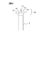
- FIG. 9 is a diagram showing the shape of the end 32 in the third modification.
- the end portion 32 in this modification has a recess 16 in addition to the first music portion 12, the second music portion 13, and the third music portion 14.
- the recess 16 exists between the first music part 12 and the second music part 13 and between the second music part 13 and the third music part 14, and is recessed toward the inside of the bobbin 3.
- the material used for the bobbin 3 can be reduced by the recess 16.
- the presence of the recess 16 forms a gap through which air flows between the coil 4 and the bobbin 3, so that the heat dissipation of the bobbin 3 and the coil 4 is improved.
- the same effect as in the first embodiment described above can be obtained.
- the recess 16 provided in the bobbin 3 is not a substantial winding surface of the coil 4.
- the substantial winding surface of the coil 4 is approximately at the position of the yarn when a thin and soft thread is wound around the winding surface of the bobbin 3 and an appropriate tension is applied. It is a surface drawn by a curve connecting with. Therefore, the bobbin 3 in the modified example 3 can also obtain the same effect of reducing the winding bulge as in the first embodiment described above.
- the bobbin 3 may have at least one end 32.
- the bobbin 3 may be a bobbin having an upper portion having the shape of the end portion 32 described above and a lower portion having a shape different from that of the end portion 32.
- the angle of the arc constituting the second music part 13 may be 180 degrees or more.
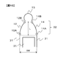
- FIG. 10 is a diagram illustrating the shape of the end 32 in the fifth modification. As shown in FIG. 10, the angle of the arc constituting the second music portion 13 may be 180 degrees or more.
- FIG. 11 a second embodiment of an electric motor which is a rotating electrical machine according to the present invention will be described.
- the same components as those in the first embodiment are denoted by the same reference numerals, and different points will be mainly described. Points that are not particularly described are the same as those in the first embodiment.
- the shape of the end portion 32 is different from that of the first embodiment.
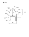
- FIG. 11 is a diagram illustrating the shape of the end portion 32A in the second embodiment.
- the end portion 32 ⁇ / b> A includes the first music portion 12, the connection portion 15, and the third music portion 14.
- the point that the radius of curvature of the first curved portion 12 is larger than half of the bobbin width BW is the same as that of the first embodiment, but is further apex from the height of the arc, that is, the boundary between the straight portion 31 and the end portion 32A.
- the longitudinal distance M to the end 12B exceeds half of the bobbin width BW.
- the radius of curvature of the third curved portion 14 is larger than half of the bobbin width BW, and the longitudinal distance M from the boundary between the straight portion 31 and the end portion 32A to the apex end 14B is It exceeds half the bobbin width BW.
- the connecting portion 15 is a straight line connecting the vertex end 12B of the first music portion 12 and the vertex end 14B of the third music portion 14.
- the apex end 12B of the first music portion 12 and the apex end 14B of the third music portion 14 are the bending defining portions.
- Each of the first curved portion 12 and the third curved portion 14 includes a contact end 12A and a contact end 14A that are ends that contact the linear portion 31, a vertex end 12B that is an end portion that does not contact the linear portion 31, and A vertex end 14B.
- the vertex end 12B and the vertex end 14B are separated from the straight line portion 31 in the longitudinal direction by more than half of the bobbin width BW.
- the bending defining portions in the present embodiment are the vertex end 12B and the vertex end 14B.
- connection part 15 may not be a straight line.
- an upward convex arc may be used as in the first embodiment, or a downward convex arc may be used.
- FIG. 12 is a diagram showing the shape of the end portion 32A in a modification of the second embodiment.
- the connecting portion 15 has a downwardly convex arc shape.
- the radius of curvature of the first curved portion 12 is larger than half of the bobbin width BW as in the second embodiment, and the length from the boundary between the straight portion 31 and the end portion 32A to the vertex end 12B.
- the direction distance M exceeds half the bobbin width BW.
- the radius of curvature of the third curved portion 14 is larger than half of the bobbin width BW, and the longitudinal distance M from the boundary between the straight portion 31 and the end portion 32A to the apex end 14B exceeds half of the bobbin width BW.
- the apex end 12B of the first bend portion 12 and the apex end 14B of the third bend portion 14 serve as a bending defining portion, so even if the connecting portion 15 is a downwardly convex arc, As with the first embodiment, the bulge of the coil 4 can be reduced.
- FIG. 13 a third embodiment of an electric motor which is a rotating electrical machine according to the present invention will be described.
- the same components as those in the first embodiment are denoted by the same reference numerals, and different points will be mainly described. Points that are not particularly described are the same as those in the first embodiment.
- the shape of the end portion 32 is mainly different from those of the first and second embodiments.
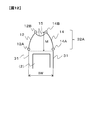
- FIG. 13 is a diagram showing the shape of the end portion 32B in the third embodiment.
- the end portion 32 ⁇ / b> B includes the first music portion 12 and the third music portion 14.
- the point that the radius of curvature of the first curved portion 12 is larger than half of the bobbin width BW is the same as that of the first embodiment, but is further apex from the height of the arc, that is, the boundary between the straight portion 31 and the end portion 32A.
- the longitudinal distance N to the end 12B exceeds half the bobbin width BW.
- the radius of curvature of the third curved portion 14 is larger than half of the bobbin width BW, and the longitudinal distance N from the boundary between the straight portion 31 and the end portion 32A to the apex end 14B is It exceeds half the bobbin width BW.
- the apex end 12B of the first music portion 12 and the apex end 14B of the third music portion 14 are joined, and this joining point becomes a bending defining portion.
- the intersection of the first music part 12 and the third music part 14 is the bending defining part in the present embodiment.
- this junction exists in the center of the width direction in the edge part 32B in FIG. 13, you may exist in the position shifted
- the bending defining portion is an intersection of the vertex end 12B and the vertex end 14B. Therefore, the configuration of the end portion 32B can be simplified.
- FIG. 14 a fourth embodiment of an electric motor which is a rotating electrical machine according to the present invention will be described.
- the same components as those in the first embodiment are denoted by the same reference numerals, and different points will be mainly described. Points that are not particularly described are the same as those in the first embodiment.
- the shape of the portion where the iron core 2 and the bobbin 3 are in contact is mainly different from that in the first embodiment.
- FIG. 14 is a view showing the shape of the bobbin 3 in the fourth embodiment.
- the bobbin 3 has a protrusion 20 or a recess 21 on the surface facing the end of the iron core 2.
- the iron core 2 combined with the bobbin 3 corresponds to the protrusion 20 or the depression 21 of the bobbin 3 and has a depression or a protrusion that is in a fitting relationship therewith.
- the protrusion 20 of the bobbin 3 and the recess of the iron core 2 or the recess 21 of the bobbin 3 and the protrusion of the iron core 2 are fitted together.
- the bobbin 3 Since the bobbin 3 is long up to the tip of the end portion 32, the bobbin 3 is likely to receive a force from the coil 4 when the coil 4 is wound. However, the relative positional relationship between the iron core 2 and the bobbin 3 due to the fitting of the protrusion and the recess. Can be kept constant.
- the bobbin 3 has the depression 21 at the upper part in the longitudinal direction and the protrusion 20 at the lower part. However, the bobbin 3 may be the depression 21, or may be the protrusion 20.
- the iron core 2 can be manufactured by various methods. However, when a plurality of thin steel plates are stacked and manufactured, the manufacturing can be simplified as follows. When a thin steel plate is punched into the cross-sectional shape of the iron core 2, dowels are formed at the same location on each steel plate. This dowel is formed by hitting a pointed metal on one side of a steel plate. Therefore, by using this dowel as the above-described depression or protrusion of the iron core 2, the step of forming the depression or protrusion on the iron core 2 can be omitted.
- the following operational effects can be obtained.
- (1) The iron core 2 and the bobbin 3 are fitted by a combination of protrusions and depressions. Since the bobbin 3 is long up to the tip of the end portion 32, the bobbin 3 is likely to receive a force from the coil 4 when the coil 4 is wound. However, the relative positional relationship between the iron core 2 and the bobbin 3 due to the fitting of the protrusion and the recess. Can be kept constant.
- FIG. 15 a fifth embodiment of an electric motor which is a rotating electrical machine according to the present invention will be described.
- the same components as those in the first embodiment are denoted by the same reference numerals, and different points will be mainly described. Points that are not particularly described are the same as those in the first embodiment.
- This embodiment is different from the first embodiment mainly in that the surface roughness of the end of the bobbin is increased.
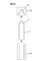
- FIG. 15 is a diagram showing the bobbin 3 and its manufacturing process in the fifth embodiment.
- the outer shape of the bobbin 3 is the same as that of the first embodiment, but differs from the first embodiment in that the surface roughness is defined. That is, the surface roughness of the end portion 32 is rougher than the surface roughness of the straight portion 31, and the friction coefficient is large. Therefore, slipping at the end 32 of the coil 4 is prevented.
- the surface roughness imparting surface 17 may be the entire end portion 32 or a part of the end portion 32.
- the bobbin 3 is formed by pouring an insulating material into the upper mold 35 and the lower mold 36.
- a roughness generator 34 corresponding to the surface roughness imparting surface 17 is formed on the inner peripheral portion of the upper mold 35, and the surface roughness imparting surface 17 is realized only by molding without requiring additional processing. be able to.
- the surface roughness of the end portion 32 is rougher than the surface roughness of the straight portion 31.
- the friction coefficient between the bobbin 3 and the coil 4 is small and slipping is likely to occur, the winding bulge may become large, but in this embodiment, the surface roughness of the end portion 32 is roughened. Therefore, slipping of the coil 4 from the bobbin 3 can be prevented, and the effect of preventing winding bulging, which is an effect obtained by the shape of the end portion 32, can be more reliably exhibited.
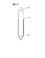
- FIG. 16 is a diagram illustrating a bobbin 3 in a modification of the fifth embodiment.
- the outer shape of the bobbin 3 is the same as that of the first embodiment, but a protrusion is provided on the surface of the end portion 32. This protrusion is provided on the surface in contact with the coil 4 to prevent the coil 4 from slipping.
- the length of the protrusion is not particularly limited, but is preferably shorter than the diameter of the coil 4.
- the end 32 has a protrusion shorter than the diameter of the coil 4 on the surface in contact with the coil 4. Therefore, slipping of the coil 4 from the bobbin 3 can be prevented, and the effect of preventing winding bulging, which is an effect obtained by the shape of the end portion 32, can be more reliably exhibited.
- FIGS. A sixth embodiment of an electric motor which is a rotating electrical machine according to the present invention will be described with reference to FIGS.
- the same components as those in the first embodiment are denoted by the same reference numerals, and different points will be mainly described. Points that are not particularly described are the same as in the fifth embodiment.
- This embodiment differs from the first embodiment mainly in that a through hole is provided at the end.
- FIG. 17 is a diagram illustrating the bobbin 3 in the sixth embodiment.
- the outer shape of the bobbin 3, that is, the shape of the surface where the bobbin 3 and the coil 4 are in contact is the same as that of the first embodiment.
- the bobbin 3 includes holes 19 penetrating in the depth direction at both ends. In other words, the hole 19 passes through a plane around which the coil 4 is wound, that is, a plane including the height direction and the width direction shown in FIG.
- the hole 19 is used when the coil 4 is wound around the bobbin 3 as described below.
- the linear portion 31 has the iron core 2 inserted therein, and the width of the resin near the boundary with the end portion 32 in the linear portion 31 is thin. Therefore, it is not realistic to provide the hole 19 in the straight portion 31, and the hole 19 is provided in the end portion 32. However, the hole 19 may exist across the straight part 31 and the end part 32.
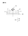
- FIG. 18 is a diagram illustrating a state in which the bobbin 3 is assembled to the winding machine 90 and the coil 4 is wound around the bobbin 3.
- the winding machine 90 includes a winding machine base 38 and a pin 37.
- the bobbin 3 is placed on the winding machine base 38, and the pin 37 is inserted into the hole 19 of the bobbin 3.
- the winding machine base 38 rotates around the rotation center 33, and the coil 4 is wound around the bobbin 3. Therefore, the force that the bobbin 3 receives from the coil 4 during winding is transmitted to the winding machine base 38 by turning the hole 19 and the pin 37. That is, it is possible to prevent the bobbin 3 from being broken by avoiding high stress from being generated inside the bobbin 3, and to regulate the relative positional relationship between the bobbin 3 and the iron core 2.
- the end portion 32 has a hole 19 that passes through a plane around which the coil is wound. Therefore, it is possible to prevent the bobbin 3 from being destroyed by avoiding the occurrence of high stress inside the bobbin 3, and to regulate the relative positional relationship between the bobbin 3 and the iron core 2.
- a recess may be provided in place of the hole 19.
- the hole 19 has a role of fixing the bobbin 3 to the winding machine base 38 in combination with the pin 37 when the winding machine base 38 rotates. Therefore, the bobbin 3 may be provided with a depression that can be fixed to the winding machine base 38 in combination with the pin 37 instead of the hole 19 that is a through hole.
- This recess is perpendicular to the plane around which the coil 4 is wound, that is, the plane including the height direction and the width direction shown in FIG. For example, a depression formed by closing one outlet of the hole 19 is a depression in this modification.
- a split iron core type obtained by dividing each salient pole portion of the stator 1 is shown as an example, but an iron core that is not a split iron core type such as an integral core may be used.
- the bobbin 3 is formed in advance and inserted from both ends of the iron core as an example.
- the bobbin 3 may be formed so as to mold the iron core 2, or may be integrated without being divided.
- the material of the bobbin 3 is resin as an example, but any material may be used as long as it can provide the necessary electrical insulation between the iron core 2 and the coil 4.
- the structure of the bobbin 3 was described mainly about the part used as the winding surface of the coil 4, the bank for preventing the position shift of the coil 4 around the winding surface, and the structure for regulating a winding position In such a case, the essence of the present invention remains unchanged.
- the winding surface around the end portion 32 of the coil 4 is advanced in the radial direction of the stator 1.
- the winding surface around the end 32 of the coil 4 may be changed in accordance with the radial direction of the stator 1 according to the target shape.
- the position of the tip of the bobbin 3 may be different in order to change the position of the tip of the coil 4 for every turn, and particularly where the coil 4 is noticeably bulging, such as the start and end of winding.
- the bobbin 3 end shape of the present invention may be applied only to the above.
- the minimum bending radius of the coil 4 is not less than half the wire diameter of the coil 4. In other words, it is desirable to determine the radius of curvature of the second curved portion 13 and the shape of the connecting portion 15 in consideration of the wire diameter of the coil 4 to be used. Further, it is desirable that the tension be wound considering that the tension that can be wound without the coil 4 being stretched is about 100 MPa and the tension that keeps the elongation at 5% is about 180 MPa.
- the winding bulge can be reduced by adopting the shape of the bobbin 3 of each of the above-described embodiments and modifications, it is not necessary to adopt a method of reducing the winding bulge by increasing the winding tension, and it is more than conventional. It is also possible to reduce damage and elongation of the coil 4 by winding with the winding tension reduced.
Landscapes
- Engineering & Computer Science (AREA)
- Power Engineering (AREA)
- Insulation, Fastening Of Motor, Generator Windings (AREA)
Abstract
回転電機は、鉄心を覆うボビンにコイルが巻き回されて形成される集中巻コイルを複数有する固定子を備える回転電機であって、ボビンは、直線部と直線部の長手方向に配される端部とを備え、端部は、直線部と接しボビンの幅の半分よりも大きな曲率半径を有する2つの曲部、および屈曲規定部を備え、屈曲規定部の少なくとも一部は直線部から長手方向にボビンの幅の半分よりも離れた位置に存在する。
Description
本発明は、回転電機に関する。
近年、電動パワーステアリングなどに用いられるモータは、高い出力密度が求められる。コイルが発生できる磁界の強さは、コイルの巻数とコイルに流れる電流の大きさによって決まり、磁界の強さはモータの出力に強い影響を与えるため、コイルに流す電流を大きくする目的のために銅線の太線化が進められている。しかし、太線の採用によって高電流化を図れる一方、モータの製造過程においては、太線化による電線の加工の難化が問題となる。一般に、電線は太い方が曲げなどの加工が難しく、集中巻コイルにおいては、ボビンに電線を巻きつける際のボビンと電線の密着性に影響する。集中巻コイルのボビンは縦横比が大きいが、このうち回転子の回転軸と略平行である長辺部と電線の密着性は、モータの出力密度に大きな影響を与える。密着性の低さは、略長方形状のボビンに電線を巻きつける際に、ボビンの輪郭に電線が沿い切れずに膨らむために生ずるものであり、ここではこの現象を巻き膨らみと呼ぶ。この巻き膨らみを抑制することは、集中巻コイルの太線化と出力密度向上の両立のためには避けられない課題である。
特許文献1には、ボビン端部を構成する2つの曲部において、コイルの巻き終わり側の曲率半径R2を、コイルの巻き始め側の曲率半径R1よりも大きくする構成が開示されている。
特許文献1には、ボビン端部を構成する2つの曲部において、コイルの巻き終わり側の曲率半径R2を、コイルの巻き始め側の曲率半径R1よりも大きくする構成が開示されている。
コイルの巻き膨らみの低減が求められる。
本発明の第1の態様による回転電機は、鉄心を覆うボビンにコイルが巻き回されて形成される集中巻コイルを複数有する固定子を備える回転電機であって、前記ボビンは、直線部と前記直線部の長手方向に配される端部とを備え、前記端部は、前記直線部と接し前記ボビンの幅の半分よりも大きな曲率半径を有する2つの曲部、および屈曲規定部を備え、前記屈曲規定部の少なくとも一部は前記直線部から前記長手方向に前記ボビンの幅の半分よりも離れた位置に存在する。
本発明によれば、コイルの巻き膨らみを低減することができる。
―第1の実施の形態―
以下、図1~図8を参照して、本発明にかかる回転電機である電動モータの第1の実施の形態を説明する。
以下、図1~図8を参照して、本発明にかかる回転電機である電動モータの第1の実施の形態を説明する。
(固定子の概要)
図1は、固定子の外観を示す図である。電動モータ100は、固定子1と不図示の回転子を備える。固定子1は複数の鉄心2を備え、それぞれの鉄心2にコイル4が集中的に巻かれている。換言すると、電動モータ100は巻き線の形態として集中巻きを採用している。コイル4に通電されると磁界が生じ、不図示の回転子が回転する。
図1は、固定子の外観を示す図である。電動モータ100は、固定子1と不図示の回転子を備える。固定子1は複数の鉄心2を備え、それぞれの鉄心2にコイル4が集中的に巻かれている。換言すると、電動モータ100は巻き線の形態として集中巻きを採用している。コイル4に通電されると磁界が生じ、不図示の回転子が回転する。
図2はコイル4が巻き回された後の状態にある鉄心2を示す図、図3はコイル4が巻き回される前の状態にある鉄心2を示す図である。以下では、図2に示す矢印Hの方向を高さ方向または長手方向、矢印Dの方向を奥行き方向、矢印Wの方向を幅方向と呼ぶ。なおここではH,D,Wが方向を表すにすぎず、寸法を表すものではないことを明確にするために一方向矢印を用いている。
鉄心2は鉄系の金属で構成される。鉄心2は、たとえば鋳造、削り出しで製造される。また鉄心2は、鉄心の断面形状に打ち抜かれた薄い鋼板を複数枚重ねて製造することや、粉末状の金属を押し固めて製造することもできる。鉄心2は、コイル4との電気的な絶縁のために、樹脂など絶縁性の材料で成形されたボビン3で覆われる。ボビン3は図3に示すように鉄心2の長手方向の両端から挿入され、ボビン3の挿入後にコイル4が巻き回される。なおコイル4の主な素材は、銅やアルミなどである。
鉄心2へのコイル4の巻回は、たとえば鉄心2とボビン3を組み合わせたものを巻線機に固定し、電線の片方の端部をボビン3あるいはその周囲の治具に固定した状態において、鉄心2とボビン3を回転させてボビン3にコイル4を巻きつける方法をとることができる。また、電線の繰出し口であるノズルを、電線を繰出しながらボビン3の周囲を旋回させることによってコイル4を巻回してもよい。なお以下では、鉄心2に巻回する前の電線もコイル4と呼ぶ。
(ボビン3の断面図)
図4は、ボビン3の断面図である。図4はコイル4が巻き回される平面で切断しているので、図4の上下が高さ方向、図4の左右が幅方向である。ボビン3をその形状により便宜的に分割すると、ボビン3は長手方向に上から端部32、直線部31、端部32に分割される。図4に示すように、ボビン3の幅を以下ではボビン幅BWと呼ぶ。
図4は、ボビン3の断面図である。図4はコイル4が巻き回される平面で切断しているので、図4の上下が高さ方向、図4の左右が幅方向である。ボビン3をその形状により便宜的に分割すると、ボビン3は長手方向に上から端部32、直線部31、端部32に分割される。図4に示すように、ボビン3の幅を以下ではボビン幅BWと呼ぶ。
直線部31の外形は直線で構成され、内部に鉄心2が挿入される空洞を有する。ただし直線部31は図3に示すように2つの部材の組み合わせにより形成されるため、図2に示すように長手方向の中間に切れ目が存在していてもよい。端部32は図4において2つ存在するが、形状は同一なのでここでは上部の端部32のみを説明する。端部32は、第1曲部12と、第2曲部13と、第3曲部14とを備える。第1曲部12および第3曲部14は、BWよりも大きい同一の曲率半径を有する円弧である。第2曲部13は、第1曲部12および第3曲部14よりも小さい曲率半径を有する円弧である。
(端部32の詳細)
図5は、端部32の詳細を示す図である。ただし図5では、それぞれの構成を明確にするために、直線部31と端部32の接合部、第1曲部12と第2曲部13の接合部、および第2曲部13と第3曲部14の接合部の間隔を開けて表示している。また図5において破線は直線部31と端部32の境界を示している。
図5は、端部32の詳細を示す図である。ただし図5では、それぞれの構成を明確にするために、直線部31と端部32の接合部、第1曲部12と第2曲部13の接合部、および第2曲部13と第3曲部14の接合部の間隔を開けて表示している。また図5において破線は直線部31と端部32の境界を示している。
第1曲部12の両端を接触端12A、頂点端12Bと呼ぶと、接触端12Aは直線部31と接触し、頂点端12Bは第2曲部13と接触する。第3曲部14の両端を接触端14A、頂点端14Bと呼ぶと、接触端14Aは直線部31と接触し、頂点端14Bは第2曲部13と接触する。第1曲部12、第2曲部13、および第3曲部14は上述した幾何的な特徴を有するので、直線部31と端部32との境界から第2曲部13の頂部までの長手方向の距離Lはボビン幅BWの半分を超える。
(コイル4の巻回過程)
図6は、ボビン3にコイル4を巻き回す過程を示す図である。図6において破線がコイル4を表す。図6では図示の都合によりボビン3とコイル4の間に隙間が生じているが、実際にはボビン3とコイル4は略密着する。コイル4はまず、図6(a)に示すように直線部31に沿って配される。次にコイル4は、図6(b)に示すように直線部31と第1曲部12の境界で軽く屈曲され、第1曲部12に沿って配される。そしてコイル4は、図6(c)に示すように第2曲部13において大きく屈曲される。このように、第2曲部13は大きな屈曲を生じさせる部位なので、以下では第2曲部13を「屈曲規定部」とも呼ぶ。最後にコイル4は、図6(d)に示すように第3曲部14と直線部31の境界で軽く屈曲される。なお以下では、図6に示した方向にコイル4を巻き付けることを、「ボビン3にコイル4を時計回りに巻回する」と言う。
図6は、ボビン3にコイル4を巻き回す過程を示す図である。図6において破線がコイル4を表す。図6では図示の都合によりボビン3とコイル4の間に隙間が生じているが、実際にはボビン3とコイル4は略密着する。コイル4はまず、図6(a)に示すように直線部31に沿って配される。次にコイル4は、図6(b)に示すように直線部31と第1曲部12の境界で軽く屈曲され、第1曲部12に沿って配される。そしてコイル4は、図6(c)に示すように第2曲部13において大きく屈曲される。このように、第2曲部13は大きな屈曲を生じさせる部位なので、以下では第2曲部13を「屈曲規定部」とも呼ぶ。最後にコイル4は、図6(d)に示すように第3曲部14と直線部31の境界で軽く屈曲される。なお以下では、図6に示した方向にコイル4を巻き付けることを、「ボビン3にコイル4を時計回りに巻回する」と言う。
(ボビンの上端と下端の相違)
ボビン3にコイル4を巻き回す際には、コイル4はボビン3の周囲を一周するごとに奥行き方向へおよそコイル4の厚み分移動する。コイルの密度を高めるために、この移動は図6に示すようにボビン3の端部で集中的に行われる。この移動はボビン3の上端部と下端部のいずれで行ってもよいが、ここでは上端部で行うとして説明を続ける。
ボビン3にコイル4を巻き回す際には、コイル4はボビン3の周囲を一周するごとに奥行き方向へおよそコイル4の厚み分移動する。コイルの密度を高めるために、この移動は図6に示すようにボビン3の端部で集中的に行われる。この移動はボビン3の上端部と下端部のいずれで行ってもよいが、ここでは上端部で行うとして説明を続ける。
図7(a)はボビン3の平面図、図7(b)はボビン3の下面図である。ただし図7ではコイル4を1層分のみ記載している。ボビン3の上端では図7(a)に示すように、コイル4がボビン3の端部を斜めに渡る。一方、ボビン3の下端では図7(b)に示すように、コイル4がボビン3の端部を平行に渡る。図7(a)と図7(b)のそれぞれにおいて、コイル4に沿ってボビン3を切断する切断面を、切断面6A、切断面6Bと呼ぶ。切断面6Bで切断して得られる断面が図4に示した切断面であり、切断面6Aで切断すると厳密には切断面の横幅はBWよりもわずかに大きくなる。しかし第1曲部12、第2曲部13、および第3曲部14のいずれもBWと同様の比率で大きくなるので、曲率半径と横幅の関係は維持される。すなわち、ボビン3の上端と下端のいずれでも以下に説明するように巻き膨らみが低減される。
(巻き膨らみの低減)
ボビン3は以下の3つの特徴的な構成を有するので、巻き膨らみが顕著に低減される。
第1の特徴的な構成は、ボビン3の端部から長辺に向かってコイル4が巻回される箇所に配される、曲率半径の大きな第3曲部14である。第3曲部14の曲率半径が大きく、直線部31と滑らかに接続されることにより、巻回されるコイル4は巻き膨らみの小さな状態で直線部31へ巻回され始めることとなる。仮に第3曲部14の曲率半径が小さな場合には、十分に曲がりきらなかったコイル4がボビン3から大きく遊離してボビン3の長辺部へ巻回され始めることとなり、巻き膨らみが大きくなる原因となる。
ボビン3は以下の3つの特徴的な構成を有するので、巻き膨らみが顕著に低減される。
第1の特徴的な構成は、ボビン3の端部から長辺に向かってコイル4が巻回される箇所に配される、曲率半径の大きな第3曲部14である。第3曲部14の曲率半径が大きく、直線部31と滑らかに接続されることにより、巻回されるコイル4は巻き膨らみの小さな状態で直線部31へ巻回され始めることとなる。仮に第3曲部14の曲率半径が小さな場合には、十分に曲がりきらなかったコイル4がボビン3から大きく遊離してボビン3の長辺部へ巻回され始めることとなり、巻き膨らみが大きくなる原因となる。
第2の特徴的な構成は、直線部31からボビンの端部、すなわち第2曲部13に向かってコイル4が巻回される箇所に配される、曲率半径の大きな第1曲部12である。第1曲部12の曲率半径が大きく、ボビン3の直線部31と滑らかに接続されることにより、巻回されるコイル4は、強い曲げの影響を受けることなく、ボビン3の先端部に向けて緩やかな曲げを伴って巻回され、すでに通過した直線部31に巻回されたコイル4の巻き膨らみの大きさを増大させない。仮に第1曲部12の曲率半径が小さな場合には、第1曲部12に沿うように曲げられるコイル4は、急激な曲げ加工の影響を曲げの基点の前方および後方の両側に受け、すでに通過した長辺部に巻回されたコイル4は、ボビン3から遊離する方向に移動する力を受け、巻き膨らみが大きくなる原因となる。
第3の特徴的な構成は、ボビン3の先端部に配されてコイル4の曲げの基点となる、屈曲規定部である第2曲部13である。ボビン3の先端部付近に屈曲規定部を設けられるので、コイル4がボビン3の端部付近で強く曲げられる。したがって、直線部31と端部32の境界付近ではコイル4を急激に曲げる必要がなく、曲げ残しなどによる巻き膨らみの増大を防ぐことができる。
(巻き膨らみ)
図8は、コイル94の巻き膨らみを抑制しない場合に生じうる問題を示す図である。図8に示すボビン93は、上述したボビン3とは異なる形状を有する。図8では、簡略化のためコイル94をボビン93に一層だけ巻回している。また図8では図6と同様に、ボビン93にコイル94を時計回りに巻回している。図8に示すように、巻き膨らみによるコイル94と鉄心92との距離は、巻き回される前後で異なる。具体的には、端部に達する前のコイル94の膨らみ98よりも、端部に達した後のコイル94の膨らみ99の方が大きく、コイル94と鉄心92との距離がより離れる。そして、この巻きふくらみにより隣接するコイル94同士の距離が短くなる。そのため巻き膨らみが大きな場合には、鉄心92同士の距離を離すなどの対策が必要になる。また巻き膨らみの影響を最小にとどめるためには、巻き膨らみ最大箇所、すなわち図8の符号99の膨らみの箇所への対策だけでは十分ではなく、ボビン93の長辺全域にわたって巻き膨らみを低減することが必要である。
図8は、コイル94の巻き膨らみを抑制しない場合に生じうる問題を示す図である。図8に示すボビン93は、上述したボビン3とは異なる形状を有する。図8では、簡略化のためコイル94をボビン93に一層だけ巻回している。また図8では図6と同様に、ボビン93にコイル94を時計回りに巻回している。図8に示すように、巻き膨らみによるコイル94と鉄心92との距離は、巻き回される前後で異なる。具体的には、端部に達する前のコイル94の膨らみ98よりも、端部に達した後のコイル94の膨らみ99の方が大きく、コイル94と鉄心92との距離がより離れる。そして、この巻きふくらみにより隣接するコイル94同士の距離が短くなる。そのため巻き膨らみが大きな場合には、鉄心92同士の距離を離すなどの対策が必要になる。また巻き膨らみの影響を最小にとどめるためには、巻き膨らみ最大箇所、すなわち図8の符号99の膨らみの箇所への対策だけでは十分ではなく、ボビン93の長辺全域にわたって巻き膨らみを低減することが必要である。
上述した第1の実施の形態によれば、次の作用効果が得られる。
(1)電動モータ100は、鉄心2を覆うボビン3にコイル4が巻き回されて形成される集中巻コイルを複数有する固定子1を備える。ボビン3は、直線部31と直線部31の長手方向に配される端部32とを備える。端部32は、直線部31と接しボビン幅BWの半分よりも大きな曲率半径を有する2つの曲部、すなわち第1曲部12および第3曲部14を備える。端部32はさらに、直線部31から長手方向にボビン幅BWの半分よりも離れて存在する屈曲規定部、たとえば第2曲部13を備える。そのため、コイル4の巻き膨らみを低減することができる。
(1)電動モータ100は、鉄心2を覆うボビン3にコイル4が巻き回されて形成される集中巻コイルを複数有する固定子1を備える。ボビン3は、直線部31と直線部31の長手方向に配される端部32とを備える。端部32は、直線部31と接しボビン幅BWの半分よりも大きな曲率半径を有する2つの曲部、すなわち第1曲部12および第3曲部14を備える。端部32はさらに、直線部31から長手方向にボビン幅BWの半分よりも離れて存在する屈曲規定部、たとえば第2曲部13を備える。そのため、コイル4の巻き膨らみを低減することができる。
(2)第2曲部13は、第1曲部12および第3曲部14よりも小さな曲率半径を有する円弧形状を有する。
(3)第1曲部12および第3曲部14は同一の曲率半径を有する。換言すると、端部32は左右対称である。そのため、図6に示したようにボビン3にコイル4を時計回りに巻回する場合だけでなく、ボビン3にコイル4を反時計回りに巻回する場合にも同様に巻きふくらみを抑制できる。集中巻モータにおいては、回転子の回転軸側から固定子の突極を見る向きにおいて、突極によってコイル4がボビン3に時計回りに巻回されるものと反時計回りに巻回されるものが混在する例が多く存在する。したがっていずれの巻回方向であっても巻き膨らみを低減できる本実施の形態におけるボビン3の形状は有用である。またボビン3が左右対称なので成形が容易である。
(4)ボビン3は、2つの端部32と1つの直線部31を備え、直線部31は2つの端部32により挟まれる。すなわち本実施の形態では、ボビン3は上端と下端に同一形状の端部32を備える。そのため、全周にわたってコイル4の巻き膨らみを低減することができる。また2つの端部32の部品を共通化できるので製作や管理のコストを低減できる。
(変形例1)
第1曲部12と第3曲部14の曲率半径は異なっていてもよい。第1曲部12の曲率半径と第3曲部14の曲率半径のそれぞれが、ボビン幅BWの半分よりも大きければよい。
第1曲部12と第3曲部14の曲率半径は異なっていてもよい。第1曲部12の曲率半径と第3曲部14の曲率半径のそれぞれが、ボビン幅BWの半分よりも大きければよい。
(変形例2)
第3曲部14の曲率半径は、第1曲部12および第3曲部14の曲率半径よりも小さいだけでなく、ボビン幅BWの半分よりも小さくしてもよい。
第3曲部14の曲率半径は、第1曲部12および第3曲部14の曲率半径よりも小さいだけでなく、ボビン幅BWの半分よりも小さくしてもよい。
(変形例3)
端部32は、第1曲部12、第2曲部13、および第3曲部14の他に直線や曲線を含んで構成されてもよい。
端部32は、第1曲部12、第2曲部13、および第3曲部14の他に直線や曲線を含んで構成されてもよい。
図9は変形例3における端部32の形状を示す図である。本変形例における端部32は、図9に示すように、第1曲部12、第2曲部13、および第3曲部14の他に窪み16を有する。窪み16は、第1曲部12と第2曲部13との間、および第2曲部13と第3曲部14との間に存在し、ボビン3の内側に向かって窪んでいる。この窪み16により、ボビン3に使用する材料を削減できる。またこの窪み16が存在することにより、コイル4とボビン3の間に空気が流れる隙間が形成されるのでボビン3およびコイル4の放熱性が向上する。なお、以下の理由により、本変形例におけるボビン3の形態であっても、上述した第1の実施の形態と同様の巻き膨らみ低減効果を得られる。
図9に示すボビン3へのコイル4の巻回を考察すると、ボビン3の窪み16にコイル4が入り込むように巻回されることは、力学的に現実的ではない。換言すると、ボビン3に設けられた窪み16は、コイル4の実質的な巻き付け面ではない。この場合の実質的なコイル4の巻き付け面は、おおよそ、ボビン3の巻き付け面に細く柔らかな糸を巻回し、適度な張力をかけた際の糸の位置に存在し、ボビン3の周囲を最短で結ぶ曲線によって描かれる面である。したがって、変形例3におけるボビン3も上述した第1の実施の形態と同様の巻き膨らみ低減効果を得られる。
(変形例4)
ボビン3は端部32を少なくとも1つ備えればよい。たとえばボビン3は、上部は上述した端部32の形状を有し、下部は端部32とは異なる形状を有するボビンとしてもよい。
ボビン3は端部32を少なくとも1つ備えればよい。たとえばボビン3は、上部は上述した端部32の形状を有し、下部は端部32とは異なる形状を有するボビンとしてもよい。
(変形例5)
第2曲部13を構成する弧の角度は180度以上でもよい。
図10は、変形例5における端部32の形状を示す図である。図10に示すように、第2曲部13を構成する弧の角度が180度以上であってもよい。
第2曲部13を構成する弧の角度は180度以上でもよい。
図10は、変形例5における端部32の形状を示す図である。図10に示すように、第2曲部13を構成する弧の角度が180度以上であってもよい。
―第2の実施の形態―
図11を参照して、本発明にかかる回転電機である電動モータの第2の実施の形態を説明する。以下の説明では、第1の実施の形態と同じ構成要素には同じ符号を付して相違点を主に説明する。特に説明しない点については、第1の実施の形態と同じである。本実施の形態では、端部32の形状が第1の実施の形態と異なる。
図11を参照して、本発明にかかる回転電機である電動モータの第2の実施の形態を説明する。以下の説明では、第1の実施の形態と同じ構成要素には同じ符号を付して相違点を主に説明する。特に説明しない点については、第1の実施の形態と同じである。本実施の形態では、端部32の形状が第1の実施の形態と異なる。
図11は、第2の実施の形態における端部32Aの形状を示す図である。端部32Aは、第1曲部12と、接続部15と、第3曲部14とから構成される。第1曲部12の曲率半径がボビン幅BWの半分よりも大きい点は第1の実施の形態と同様であるが、さらに弧の高さ、すなわち直線部31と端部32Aとの境界から頂点端12Bまでの長手方向の距離Mがボビン幅BWの半分を超える。第3曲部14も同様であり、第3曲部14の曲率半径はボビン幅BWの半分よりも大きく、直線部31と端部32Aとの境界から頂点端14Bまでの長手方向の距離Mがボビン幅BWの半分を超える。接続部15は、第1曲部12の頂点端12Bと第3曲部14の頂点端14Bとを接続する直線である。
本実施の形態では、第1曲部12の頂点端12B、および第3曲部14の頂点端14Bが屈曲規定部となる。
上述した第2の実施の形態によれば、次の作用効果が得られる。
(1)第1曲部12と第3曲部14のそれぞれは、直線部31と接する端部である接触端12Aおよび接触端14Aと、直線部31と接触しない端部である頂点端12Bおよび頂点端14Bとを備える。頂点端12Bおよび頂点端14Bは、直線部31から長手方向にボビン幅BWの半分よりも離れている。本実施の形態における屈曲規定部は、頂点端12Bおよび頂点端14Bである。
(1)第1曲部12と第3曲部14のそれぞれは、直線部31と接する端部である接触端12Aおよび接触端14Aと、直線部31と接触しない端部である頂点端12Bおよび頂点端14Bとを備える。頂点端12Bおよび頂点端14Bは、直線部31から長手方向にボビン幅BWの半分よりも離れている。本実施の形態における屈曲規定部は、頂点端12Bおよび頂点端14Bである。
(第2の実施の形態の変形例)
接続部15は直線でなくてもよい。たとえば第1の実施の形態と同様に上に凸の円弧でもよいし、下に凸の円弧でもよい。
図12は、第2の実施の形態の変形例における端部32Aの形状を示す図である。接続部15は下に凸の円弧形状を有する。本変形例においても、第2の実施の形態と同様に第1曲部12の曲率半径はボビン幅BWの半分よりも大きく、直線部31と端部32Aとの境界から頂点端12Bまでの長手方向の距離Mがボビン幅BWの半分を超える。また第3曲部14の曲率半径はボビン幅BWの半分よりも大きく、直線部31と端部32Aとの境界から頂点端14Bまでの長手方向の距離Mがボビン幅BWの半分を超える。本実施の形態では第1曲部12の頂点端12B、および第3曲部14の頂点端14Bが屈曲規定部の役割を果たすので、接続部15が下に凸の円弧であっても、第1の実施の形態と同様にコイル4の巻き膨らみを低減することができる。
―第3の実施の形態―
図13を参照して、本発明にかかる回転電機である電動モータの第3の実施の形態を説明する。以下の説明では、第1の実施の形態と同じ構成要素には同じ符号を付して相違点を主に説明する。特に説明しない点については、第1の実施の形態と同じである。本実施の形態では、主に、端部32の形状が第1および第2の実施の形態と異なる。
図13を参照して、本発明にかかる回転電機である電動モータの第3の実施の形態を説明する。以下の説明では、第1の実施の形態と同じ構成要素には同じ符号を付して相違点を主に説明する。特に説明しない点については、第1の実施の形態と同じである。本実施の形態では、主に、端部32の形状が第1および第2の実施の形態と異なる。
図13は、第3の実施の形態における端部32Bの形状を示す図である。ただし図13では、それぞれの構成を明確にするために、直線部31と端部32Bの接合部、および第1曲部12と第3曲部14の接合部の間隔を開けて表示している。端部32Bは、第1曲部12と、第3曲部14とから構成される。第1曲部12の曲率半径がボビン幅BWの半分よりも大きい点は第1の実施の形態と同様であるが、さらに弧の高さ、すなわち直線部31と端部32Aとの境界から頂点端12Bまでの長手方向の距離Nがボビン幅BWの半分を超える。第3曲部14も同様であり、第3曲部14の曲率半径はボビン幅BWの半分よりも大きく、直線部31と端部32Aとの境界から頂点端14Bまでの長手方向の距離Nがボビン幅BWの半分を超える。
本実施の形態では、第1曲部12の頂点端12Bと第3曲部14の頂点端14Bとが接合しており、この接合点が屈曲規定部となる。換言すると、第1曲部12と第3曲部14の交点が本実施の形態における屈曲規定部である。なおこの接合点は、図13では端部32Bにおける幅方向の中心に存在するが、幅方向の中心からずれた位置に存在してもよい。
上述した第3の実施の形態によれば、次の作用効果が得られる。
(1)屈曲規定部は、頂点端12Bおよび頂点端14Bの交点である。そのため端部32Bの構成を簡素化できる。
(1)屈曲規定部は、頂点端12Bおよび頂点端14Bの交点である。そのため端部32Bの構成を簡素化できる。
―第4の実施の形態―
図14を参照して、本発明にかかる回転電機である電動モータの第4の実施の形態を説明する。以下の説明では、第1の実施の形態と同じ構成要素には同じ符号を付して相違点を主に説明する。特に説明しない点については、第1の実施の形態と同じである。本実施の形態では、主に、鉄心2とボビン3の接する箇所の形状が、第1の実施の形態と異なる。
図14を参照して、本発明にかかる回転電機である電動モータの第4の実施の形態を説明する。以下の説明では、第1の実施の形態と同じ構成要素には同じ符号を付して相違点を主に説明する。特に説明しない点については、第1の実施の形態と同じである。本実施の形態では、主に、鉄心2とボビン3の接する箇所の形状が、第1の実施の形態と異なる。
(構成)
図14は第4の実施の形態におけるボビン3の形状を示す図である。ボビン3は鉄心2の端部と正対する面に、突起20あるいは窪み21を有する。このボビン3と組み合わせられる鉄心2は、ボビン3の突起20あるいは窪み21に対応し、これとはめ合いの関係となる窪みあるいは突起を有する。ボビン3の突起20と鉄心2のくぼみ、またはボビン3の窪み21と鉄心2の突起が嵌め合わされる。ボビン3は端部32の先端までが長いのでコイル4を巻回する際にボビン3がコイル4から力を受けやすいが、突起と窪みの嵌め合いにより鉄心2とボビン3の相対的な位置関係を一定に保つことができる。なお図14では、ボビン3は長手方向の上部に窪み21を有し下部に突起20を有するが、いずれも窪み21であってもよいし、いずれも突起20であってもよい。
図14は第4の実施の形態におけるボビン3の形状を示す図である。ボビン3は鉄心2の端部と正対する面に、突起20あるいは窪み21を有する。このボビン3と組み合わせられる鉄心2は、ボビン3の突起20あるいは窪み21に対応し、これとはめ合いの関係となる窪みあるいは突起を有する。ボビン3の突起20と鉄心2のくぼみ、またはボビン3の窪み21と鉄心2の突起が嵌め合わされる。ボビン3は端部32の先端までが長いのでコイル4を巻回する際にボビン3がコイル4から力を受けやすいが、突起と窪みの嵌め合いにより鉄心2とボビン3の相対的な位置関係を一定に保つことができる。なお図14では、ボビン3は長手方向の上部に窪み21を有し下部に突起20を有するが、いずれも窪み21であってもよいし、いずれも突起20であってもよい。
(鉄心2の製造方法)
鉄心2は様々な方法で製造できるが、薄い鋼板を複数枚重ねて製造する場合は以下のように製造を簡略化できる。薄い鋼板を鉄心2の断面形状に打ち抜く際に、それぞれの鋼板には同じ個所にダボが形成される。このダボは、鋼板の片側に先端の尖った金属を打ち付けるなどして形成されるものである。そこでこのダボを上述した鉄心2の窪みまたは突起として利用することで、鉄心2に窪みまたは突起を形成する工程を省略できる。
鉄心2は様々な方法で製造できるが、薄い鋼板を複数枚重ねて製造する場合は以下のように製造を簡略化できる。薄い鋼板を鉄心2の断面形状に打ち抜く際に、それぞれの鋼板には同じ個所にダボが形成される。このダボは、鋼板の片側に先端の尖った金属を打ち付けるなどして形成されるものである。そこでこのダボを上述した鉄心2の窪みまたは突起として利用することで、鉄心2に窪みまたは突起を形成する工程を省略できる。
上述した第4の実施の形態によれば、次の作用効果が得られる。
(1)鉄心2とボビン3は、突起と窪みの組み合わせにより嵌合される。ボビン3は端部32の先端までが長いのでコイル4を巻回する際にボビン3がコイル4から力を受けやすいが、突起と窪みの嵌め合いにより鉄心2とボビン3の相対的な位置関係を一定に保つことができる。
(1)鉄心2とボビン3は、突起と窪みの組み合わせにより嵌合される。ボビン3は端部32の先端までが長いのでコイル4を巻回する際にボビン3がコイル4から力を受けやすいが、突起と窪みの嵌め合いにより鉄心2とボビン3の相対的な位置関係を一定に保つことができる。
―第5の実施の形態―
図15を参照して、本発明にかかる回転電機である電動モータの第5の実施の形態を説明する。以下の説明では、第1の実施の形態と同じ構成要素には同じ符号を付して相違点を主に説明する。特に説明しない点については、第1の実施の形態と同じである。本実施の形態では、主に、ボビンの端部の表面粗さを粗くする点で、第1の実施の形態と異なる。
図15を参照して、本発明にかかる回転電機である電動モータの第5の実施の形態を説明する。以下の説明では、第1の実施の形態と同じ構成要素には同じ符号を付して相違点を主に説明する。特に説明しない点については、第1の実施の形態と同じである。本実施の形態では、主に、ボビンの端部の表面粗さを粗くする点で、第1の実施の形態と異なる。
図15は、第5の実施の形態におけるボビン3およびその製造工程を示す図である。ボビン3の外形は第1の実施の形態と同様であるが、表面粗さを規定する点が第1の実施の形態と異なる。すなわち、端部32の表面粗さは、直線部31の表面粗さよりも粗く、摩擦係数が大きい。そのため、コイル4の端部32における滑りが防止される。表面粗さを粗くする領域を表面粗さ付与面17と呼ぶと、表面粗さ付与面17は端部32の全域であってもよいし、端部32の一部であってもよい。
ボビン3は、上部金型35および下部金型36の中に絶縁性の材料を流し込んで成形される。上部金型35の内周部には、表面粗さ付与面17に対応する粗さ生成部34が形成されており、追加の加工を要さず成形のみによって表面粗さ付与面17を実現することができる。
上述した第5の実施の形態によれば、次の作用効果が得られる。
(1)端部32の表面粗さは、直線部31の表面粗さよりも粗い。ボビン3~コイル4間の摩擦係数が小さく滑りが発生しやすい場合には巻き膨らみが大きくなる可能性があるが、本実施の形態では端部32の表面粗さを粗くした。そのためコイル4のボビン3からの滑りを防止し、端部32の形状により得られる効果である巻き膨らみの防止の効果をより確実に奏することができる。
(1)端部32の表面粗さは、直線部31の表面粗さよりも粗い。ボビン3~コイル4間の摩擦係数が小さく滑りが発生しやすい場合には巻き膨らみが大きくなる可能性があるが、本実施の形態では端部32の表面粗さを粗くした。そのためコイル4のボビン3からの滑りを防止し、端部32の形状により得られる効果である巻き膨らみの防止の効果をより確実に奏することができる。
(第5の実施の形態の変形例)
表面粗さを加工する代わりに突起を設けてもよい。
図16は、第5の実施の形態の変形例におけるボビン3を示す図である。ボビン3の外形は第1の実施の形態と同様であるが、端部32の表面に突起が設けられている。この突起はコイル4と接する面に設けられ、コイル4の滑りを防止する。突起の長さは特に限定されないが、コイル4の直径よりも短いことが望ましい。
表面粗さを加工する代わりに突起を設けてもよい。
図16は、第5の実施の形態の変形例におけるボビン3を示す図である。ボビン3の外形は第1の実施の形態と同様であるが、端部32の表面に突起が設けられている。この突起はコイル4と接する面に設けられ、コイル4の滑りを防止する。突起の長さは特に限定されないが、コイル4の直径よりも短いことが望ましい。
本変形例によれば、次の作用効果が得られる。
(1)端部32はコイル4と接する面にコイル4の直径よりも短い突起を有する。そのためコイル4のボビン3からの滑りを防止し、端部32の形状により得られる効果である巻き膨らみの防止の効果をより確実に奏することができる。
(1)端部32はコイル4と接する面にコイル4の直径よりも短い突起を有する。そのためコイル4のボビン3からの滑りを防止し、端部32の形状により得られる効果である巻き膨らみの防止の効果をより確実に奏することができる。
―第6の実施の形態―
図17~図18を参照して、本発明にかかる回転電機である電動モータの第6の実施の形態を説明する。以下の説明では、第1の実施の形態と同じ構成要素には同じ符号を付して相違点を主に説明する。特に説明しない点については、第5の実施の形態と同じである。本実施の形態では、主に、端部に貫通穴が備えられる点で、第1の実施の形態と異なる。
図17~図18を参照して、本発明にかかる回転電機である電動モータの第6の実施の形態を説明する。以下の説明では、第1の実施の形態と同じ構成要素には同じ符号を付して相違点を主に説明する。特に説明しない点については、第5の実施の形態と同じである。本実施の形態では、主に、端部に貫通穴が備えられる点で、第1の実施の形態と異なる。
図17は、第6の実施の形態におけるボビン3を示す図である。ボビン3の外形、すなわちボビン3とコイル4が接する面の形状は第1の実施の形態と同様である。ボビン3は、奥行き方向に貫通する穴19を両端に備える。換言すると、穴19はコイル4が巻き回される平面、すなわち図17に示される高さ方向と幅方向を含む平面、を貫くものである。この穴19は以下に説明するようにボビン3にコイル4を巻回する際に利用される。なお直線部31は内部に鉄心2が挿入され、直線部31における端部32との境界付近の樹脂の幅は薄い。そのため直線部31に穴19を設けることは現実的ではなく、穴19は端部32に設けられることになる。ただし穴19が直線部31と端部32に跨って存在してもよい。
図18は、巻線機90にボビン3を組み付けてボビン3にコイル4を巻回する様子を示す図である。巻線機90は、巻線機土台38とピン37とを備える。ボビン3にコイル4を巻回す際には、巻線機土台38の上にボビン3が置かれ、ボビン3の穴19にピン37が差し込まれる。そして巻線機土台38が回転中心33を中心に回転して、コイル4がボビン3に巻回される。そのため巻線時にボビン3がコイル4から受ける力は、穴19、およびピン37を回して巻線機土台38に伝わる。すなわち、ボビン3の内部に高い応力が発生することを回避してボビン3が破壊されることを防止するとともに、ボビン3と鉄心2の相対的な位置関係を規制することができる。
上述した第6の実施の形態によれば、次の作用効果が得られる。
(1)端部32は、コイルが巻き回される平面を貫く穴19を有する。そのためボビン3の内部に高い応力が発生することを回避してボビン3が破壊されることを防止するとともに、ボビン3と鉄心2の相対的な位置関係を規制することができる。
(1)端部32は、コイルが巻き回される平面を貫く穴19を有する。そのためボビン3の内部に高い応力が発生することを回避してボビン3が破壊されることを防止するとともに、ボビン3と鉄心2の相対的な位置関係を規制することができる。
(第6の実施の形態の変形例)
穴19の代わりに窪みを設けてもよい。第6の実施の形態において穴19は、巻線機土台38が回転する際にピン37と組み合わされてボビン3を巻線機土台38に固定する役割を有していた。そのためボビン3は貫通穴である穴19の代わりにピン37と組み合わされて、巻線機土台38に固定することができる窪みを備えてもよい。この窪みは、コイル4が巻き回される平面、すなわち図17に示される高さ方向と幅方向を含む平面に垂直である。たとえば、穴19の一方の出口を塞ぐことにより形成される窪みが本変形例における窪みである。
穴19の代わりに窪みを設けてもよい。第6の実施の形態において穴19は、巻線機土台38が回転する際にピン37と組み合わされてボビン3を巻線機土台38に固定する役割を有していた。そのためボビン3は貫通穴である穴19の代わりにピン37と組み合わされて、巻線機土台38に固定することができる窪みを備えてもよい。この窪みは、コイル4が巻き回される平面、すなわち図17に示される高さ方向と幅方向を含む平面に垂直である。たとえば、穴19の一方の出口を塞ぐことにより形成される窪みが本変形例における窪みである。
上述した各実施の形態および変形例では、固定子1の各突極部を分割した分割鉄心型を例に挙げて図示しているが、一体コアなどの分割鉄心型でない鉄心であってもよい。また、ボビン3は、あらかじめ成形し、鉄心の両端から挿入する方法を例に挙げたが、鉄心2をモールドするように成形してもよいし、分割されずに一体であってもよい。ボビン3の材質は、一例として樹脂を挙げたが、鉄心2とコイル4の間に必要なだけの電気的な絶縁を提供できればよく、材質は問わない。またボビン3の構造は、主にコイル4の巻き付け面となる箇所について記述したが、巻き付け面の周囲に、コイル4の位置ずれを防止するための土手や、巻回位置を規制するための構造物を設けてもよく、そのような場合でも本発明の本質は不変である。
上述した各実施の形態および変形例では、コイル4の端部32への巻き付け面を固定子1の径方向に進んだ場合の形状の変化に言及していない。しかし、目的とする形状にあわせて、コイル4の端部32への巻き付け面を固定子1の径方向にあわせて変化させてもよい。たとえば、一周の巻回ごとにコイル4の先端の位置を変化させるためにボビン3の先端の位置が異なってもよいし、コイル4の巻き始めや巻き終わり箇所など、特に巻き膨らみの顕著な箇所のみに本発明のボビン3端部形状を適用してもよい。
端部32の詳細な形状は、コイル4の最小曲げ半径や、巻回時にコイル4にかかる張力に留意することが望ましい。コイル4の絶縁被膜の破壊を防止することを考えると、コイル4の最小曲げ半径は、コイル4の線径の半分以上であることが望ましい。換言すると、第2曲部13の曲率半径や接続部15の形状などは、使用するコイル4の線径を考慮して決定することが望ましい。また、張力はコイル4が伸びずに巻回できる張力がおよそ100MPaであることや伸びを5%に留める張力がおよそ180MPaであることを考慮して巻回されることが望ましい。なお上述した各実施の形態および変形例のボビン3の形状を採用することにより巻き膨らみが低減できるため、巻線張力を強めることにより巻き膨らみを低減する手法を採用する必要がなく、従来よりも巻線張力を低減させて巻回することにより、コイル4の損傷や伸びを低減することも可能である。
上述した各実施の形態および変形例は、それぞれ組み合わせてもよい。たとえば第4の実施の形態、第5の実施の形態、第6の実施の形態に示す特徴を全て兼ね備えるボビンも本発明の範囲に含まれる。上記では、種々の実施の形態および変形例を説明したが、本発明はこれらの内容に限定されるものではない。本発明の技術的思想の範囲内で考えられるその他の態様も本発明の範囲内に含まれる。
次の優先権基礎出願の開示内容は引用文としてここに組み込まれる。
日本国特許出願2017-112991号(2017年6月7日出願)
日本国特許出願2017-112991号(2017年6月7日出願)
1…固定子
2…鉄心
3…ボビン
4…コイル
12…第1曲部
12A、14A…接続端
12B、14B…頂点端
13…第2曲部
14…第3曲部
19…穴
20…突起
21…窪み
31…直線部
32、32B…端部
100…電動モータ
2…鉄心
3…ボビン
4…コイル
12…第1曲部
12A、14A…接続端
12B、14B…頂点端
13…第2曲部
14…第3曲部
19…穴
20…突起
21…窪み
31…直線部
32、32B…端部
100…電動モータ
Claims (10)
- 鉄心を覆うボビンにコイルが巻き回されて形成される集中巻コイルを複数有する固定子を備える回転電機であって、
前記ボビンは、直線部と前記直線部の長手方向に配される端部とを備え、
前記端部は、前記直線部と接し前記ボビンの幅の半分よりも大きな曲率半径を有する2つの曲部と屈曲規定部とを備え、
前記屈曲規定部の少なくとも一部は前記直線部から前記長手方向に前記ボビンの幅の半分よりも離れた位置に存在する回転電機。 - 請求項1に記載の回転電機において、
前記屈曲規定部は、前記2つの曲部の交点である回転電機。 - 請求項1に記載の回転電機において、
前記屈曲規定部は、前記ボビンの幅の半分よりも小さな曲率半径を有する円弧形状を有する回転電機。 - 請求項1に記載の回転電機において、
前記2つの曲部のそれぞれは、前記直線部と接する端部である接触端と前記直線部と接触しない端部である頂点端とを備え、
前記2つの曲部の前記頂点端は、前記直線部から前記長手方向に前記ボビンの幅の半分よりも離れており、
前記屈曲規定部は、前記頂点端である回転電機。 - 請求項1に記載の回転電機において、
前記鉄心と前記ボビンは、突起と窪みの組み合わせにより接合される回転電機。 - 請求項1に記載の回転電機において、
前記端部の表面粗さは、前記直線部の表面粗さよりも粗い回転電機。 - 請求項1に記載の回転電機において、
前記端部は前記コイルと接する面に前記コイルの直径よりも短い突起を有する回転電機。 - 請求項1に記載の回転電機において、
前記端部は、前記コイルが巻き回される平面を貫く穴、または前記平面に垂直な窪みを有する回転電機。 - 請求項1に記載の回転電機において、
前記2つの曲部は同一の曲率半径を有する回転電機。 - 請求項1に記載の回転電機において、
前記ボビンは、2つの前記端部と1つの前記直線部を備え、前記直線部は2つの前記端部により挟まれる回転電機。
Applications Claiming Priority (2)
| Application Number | Priority Date | Filing Date | Title |
|---|---|---|---|
| JP2017-112991 | 2017-06-07 | ||
| JP2017112991A JP6917787B2 (ja) | 2017-06-07 | 2017-06-07 | 回転電機 |
Publications (1)
| Publication Number | Publication Date |
|---|---|
| WO2018225385A1 true WO2018225385A1 (ja) | 2018-12-13 |
Family
ID=64565767
Family Applications (1)
| Application Number | Title | Priority Date | Filing Date |
|---|---|---|---|
| PCT/JP2018/015845 Ceased WO2018225385A1 (ja) | 2017-06-07 | 2018-04-17 | 回転電機 |
Country Status (2)
| Country | Link |
|---|---|
| JP (1) | JP6917787B2 (ja) |
| WO (1) | WO2018225385A1 (ja) |
Families Citing this family (1)
| Publication number | Priority date | Publication date | Assignee | Title |
|---|---|---|---|---|
| JP2024046303A (ja) * | 2022-09-22 | 2024-04-03 | 株式会社デンソー | ステータ及びモータ |
Citations (8)
| Publication number | Priority date | Publication date | Assignee | Title |
|---|---|---|---|---|
| JPS6122167U (ja) * | 1984-07-11 | 1986-02-08 | 東洋電機製造株式会社 | 直流機直巻コイルの固定構造 |
| JPH02110979U (ja) * | 1989-02-16 | 1990-09-05 | ||
| JPH0515650U (ja) * | 1991-08-08 | 1993-02-26 | 株式会社安川電機 | 回転電機の絶縁構造 |
| JP2005229703A (ja) * | 2004-02-12 | 2005-08-25 | Sanko Kiki Co Ltd | ステータコア用インシュレータ及びステータコアへの巻線方法 |
| JP2010263675A (ja) * | 2009-04-30 | 2010-11-18 | Mitsubishi Electric Corp | 電機子 |
| JP2012231670A (ja) * | 2012-07-18 | 2012-11-22 | Nsk Ltd | 回転電動機のコイル機構用プレート部材 |
| WO2015155879A1 (ja) * | 2014-04-11 | 2015-10-15 | 株式会社日立産機システム | アキシャルエアギャップ型回転電機 |
| JP2016005353A (ja) * | 2014-06-17 | 2016-01-12 | セイコーエプソン株式会社 | 電気機械装置、ロボット、移動体、及び電気機械装置の製造方法 |
-
2017
- 2017-06-07 JP JP2017112991A patent/JP6917787B2/ja active Active
-
2018
- 2018-04-17 WO PCT/JP2018/015845 patent/WO2018225385A1/ja not_active Ceased
Patent Citations (8)
| Publication number | Priority date | Publication date | Assignee | Title |
|---|---|---|---|---|
| JPS6122167U (ja) * | 1984-07-11 | 1986-02-08 | 東洋電機製造株式会社 | 直流機直巻コイルの固定構造 |
| JPH02110979U (ja) * | 1989-02-16 | 1990-09-05 | ||
| JPH0515650U (ja) * | 1991-08-08 | 1993-02-26 | 株式会社安川電機 | 回転電機の絶縁構造 |
| JP2005229703A (ja) * | 2004-02-12 | 2005-08-25 | Sanko Kiki Co Ltd | ステータコア用インシュレータ及びステータコアへの巻線方法 |
| JP2010263675A (ja) * | 2009-04-30 | 2010-11-18 | Mitsubishi Electric Corp | 電機子 |
| JP2012231670A (ja) * | 2012-07-18 | 2012-11-22 | Nsk Ltd | 回転電動機のコイル機構用プレート部材 |
| WO2015155879A1 (ja) * | 2014-04-11 | 2015-10-15 | 株式会社日立産機システム | アキシャルエアギャップ型回転電機 |
| JP2016005353A (ja) * | 2014-06-17 | 2016-01-12 | セイコーエプソン株式会社 | 電気機械装置、ロボット、移動体、及び電気機械装置の製造方法 |
Also Published As
| Publication number | Publication date |
|---|---|
| JP2018207717A (ja) | 2018-12-27 |
| JP6917787B2 (ja) | 2021-08-11 |
Similar Documents
| Publication | Publication Date | Title |
|---|---|---|
| JP6273499B2 (ja) | 永久磁石埋込型電動機およびその製造方法 | |
| JP2009112141A (ja) | 回転機の固定子 | |
| JP4767579B2 (ja) | 電動機の固定子 | |
| JP2012023861A (ja) | 電機子鉄心とモータ | |
| JP5082524B2 (ja) | 絶縁インシュレータ並びにステータの構造及び製造方法 | |
| JP2011147312A (ja) | ステータおよびモータ | |
| EP3200319B1 (en) | Stator assembly, and, motor and electric pump having the same | |
| JP4781197B2 (ja) | 分割積層鉄心及びこの分割積層鉄心を用いた回転電機の固定子鉄心 | |
| CN204481596U (zh) | 绝缘体及旋转电机 | |
| CN108565997A (zh) | 预制定子冲片、电机定子与电机 | |
| JP5034376B2 (ja) | 磁心、電機子、回転電機及び圧縮機 | |
| JP2008167518A (ja) | 固定子 | |
| JP2005224054A (ja) | アキシャルギャップ型電動機 | |
| JP2008043106A (ja) | モータ用分割コア | |
| JP2016116421A (ja) | 回転電機 | |
| JP6917787B2 (ja) | 回転電機 | |
| JP6416417B2 (ja) | 回転電機の固定子、回転電機、および回転電機の固定子の製造方法 | |
| JP2009060754A (ja) | ステータ用コア、ステータ、その組立方法およびモータ | |
| JP2007082282A (ja) | ステータコア、それを用いたモータ及びその製造方法 | |
| JP7038527B2 (ja) | 回転電機用磁性くさび、回転電機用磁性くさびの製造方法、および、回転電機 | |
| JP5109737B2 (ja) | 分割ステータコアの製造方法 | |
| JP2015119537A (ja) | 電動機及び電動機用ボビン | |
| JP2015171163A (ja) | ロータ | |
| JP5387225B2 (ja) | 電機子用ヨーク及び電機子 | |
| KR20150000944A (ko) | 전동기용 스테이터 조립체 |
Legal Events
| Date | Code | Title | Description |
|---|---|---|---|
| 121 | Ep: the epo has been informed by wipo that ep was designated in this application |
Ref document number: 18813032 Country of ref document: EP Kind code of ref document: A1 |
|
| NENP | Non-entry into the national phase |
Ref country code: DE |
|
| 122 | Ep: pct application non-entry in european phase |
Ref document number: 18813032 Country of ref document: EP Kind code of ref document: A1 |