WO2018225331A1 - カテーテル - Google Patents
カテーテル Download PDFInfo
- Publication number
- WO2018225331A1 WO2018225331A1 PCT/JP2018/010883 JP2018010883W WO2018225331A1 WO 2018225331 A1 WO2018225331 A1 WO 2018225331A1 JP 2018010883 W JP2018010883 W JP 2018010883W WO 2018225331 A1 WO2018225331 A1 WO 2018225331A1
- Authority
- WO
- WIPO (PCT)
- Prior art keywords
- blood
- tube
- catheter
- lumen
- feeding hole
- Prior art date
- Legal status (The legal status is an assumption and is not a legal conclusion. Google has not performed a legal analysis and makes no representation as to the accuracy of the status listed.)
- Ceased
Links
Images






Classifications
-
- A—HUMAN NECESSITIES
- A61—MEDICAL OR VETERINARY SCIENCE; HYGIENE
- A61M—DEVICES FOR INTRODUCING MEDIA INTO, OR ONTO, THE BODY; DEVICES FOR TRANSDUCING BODY MEDIA OR FOR TAKING MEDIA FROM THE BODY; DEVICES FOR PRODUCING OR ENDING SLEEP OR STUPOR
- A61M25/00—Catheters; Hollow probes
- A61M25/0021—Catheters; Hollow probes characterised by the form of the tubing
- A61M25/0023—Catheters; Hollow probes characterised by the form of the tubing by the form of the lumen, e.g. cross-section, variable diameter
- A61M25/0026—Multi-lumen catheters with stationary elements
- A61M25/003—Multi-lumen catheters with stationary elements characterized by features relating to least one lumen located at the distal part of the catheter, e.g. filters, plugs or valves
-
- A—HUMAN NECESSITIES
- A61—MEDICAL OR VETERINARY SCIENCE; HYGIENE
- A61M—DEVICES FOR INTRODUCING MEDIA INTO, OR ONTO, THE BODY; DEVICES FOR TRANSDUCING BODY MEDIA OR FOR TAKING MEDIA FROM THE BODY; DEVICES FOR PRODUCING OR ENDING SLEEP OR STUPOR
- A61M25/00—Catheters; Hollow probes
- A61M25/0067—Catheters; Hollow probes characterised by the distal end, e.g. tips
- A61M25/0068—Static characteristics of the catheter tip, e.g. shape, atraumatic tip, curved tip or tip structure
- A61M25/007—Side holes, e.g. their profiles or arrangements; Provisions to keep side holes unblocked
-
- A—HUMAN NECESSITIES
- A61—MEDICAL OR VETERINARY SCIENCE; HYGIENE
- A61M—DEVICES FOR INTRODUCING MEDIA INTO, OR ONTO, THE BODY; DEVICES FOR TRANSDUCING BODY MEDIA OR FOR TAKING MEDIA FROM THE BODY; DEVICES FOR PRODUCING OR ENDING SLEEP OR STUPOR
- A61M1/00—Suction or pumping devices for medical purposes; Devices for carrying-off, for treatment of, or for carrying-over, body-liquids; Drainage systems
- A61M1/36—Other treatment of blood in a by-pass of the natural circulatory system, e.g. temperature adaptation, irradiation ; Extra-corporeal blood circuits
- A61M1/3607—Regulation parameters
-
- A—HUMAN NECESSITIES
- A61—MEDICAL OR VETERINARY SCIENCE; HYGIENE
- A61M—DEVICES FOR INTRODUCING MEDIA INTO, OR ONTO, THE BODY; DEVICES FOR TRANSDUCING BODY MEDIA OR FOR TAKING MEDIA FROM THE BODY; DEVICES FOR PRODUCING OR ENDING SLEEP OR STUPOR
- A61M1/00—Suction or pumping devices for medical purposes; Devices for carrying-off, for treatment of, or for carrying-over, body-liquids; Drainage systems
- A61M1/36—Other treatment of blood in a by-pass of the natural circulatory system, e.g. temperature adaptation, irradiation ; Extra-corporeal blood circuits
- A61M1/3621—Extra-corporeal blood circuits
- A61M1/3653—Interfaces between patient blood circulation and extra-corporal blood circuit
- A61M1/3659—Cannulae pertaining to extracorporeal circulation
-
- A—HUMAN NECESSITIES
- A61—MEDICAL OR VETERINARY SCIENCE; HYGIENE
- A61M—DEVICES FOR INTRODUCING MEDIA INTO, OR ONTO, THE BODY; DEVICES FOR TRANSDUCING BODY MEDIA OR FOR TAKING MEDIA FROM THE BODY; DEVICES FOR PRODUCING OR ENDING SLEEP OR STUPOR
- A61M1/00—Suction or pumping devices for medical purposes; Devices for carrying-off, for treatment of, or for carrying-over, body-liquids; Drainage systems
- A61M1/36—Other treatment of blood in a by-pass of the natural circulatory system, e.g. temperature adaptation, irradiation ; Extra-corporeal blood circuits
- A61M1/3621—Extra-corporeal blood circuits
- A61M1/3666—Cardiac or cardiopulmonary bypass, e.g. heart-lung machines
-
- A—HUMAN NECESSITIES
- A61—MEDICAL OR VETERINARY SCIENCE; HYGIENE
- A61M—DEVICES FOR INTRODUCING MEDIA INTO, OR ONTO, THE BODY; DEVICES FOR TRANSDUCING BODY MEDIA OR FOR TAKING MEDIA FROM THE BODY; DEVICES FOR PRODUCING OR ENDING SLEEP OR STUPOR
- A61M25/00—Catheters; Hollow probes
- A61M25/0021—Catheters; Hollow probes characterised by the form of the tubing
- A61M25/0023—Catheters; Hollow probes characterised by the form of the tubing by the form of the lumen, e.g. cross-section, variable diameter
- A61M25/0026—Multi-lumen catheters with stationary elements
- A61M25/003—Multi-lumen catheters with stationary elements characterized by features relating to least one lumen located at the distal part of the catheter, e.g. filters, plugs or valves
- A61M2025/0031—Multi-lumen catheters with stationary elements characterized by features relating to least one lumen located at the distal part of the catheter, e.g. filters, plugs or valves characterized by lumina for withdrawing or delivering, i.e. used for extracorporeal circuit treatment
-
- A—HUMAN NECESSITIES
- A61—MEDICAL OR VETERINARY SCIENCE; HYGIENE
- A61M—DEVICES FOR INTRODUCING MEDIA INTO, OR ONTO, THE BODY; DEVICES FOR TRANSDUCING BODY MEDIA OR FOR TAKING MEDIA FROM THE BODY; DEVICES FOR PRODUCING OR ENDING SLEEP OR STUPOR
- A61M25/00—Catheters; Hollow probes
- A61M25/01—Introducing, guiding, advancing, emplacing or holding catheters
- A61M25/0102—Insertion or introduction using an inner stiffening member, e.g. stylet or push-rod
Definitions
- the present invention relates to a catheter having a blood feeding hole for feeding blood to a living body.
- PCPS percutaneous cardiopulmonary support
- the extracorporeal circulation apparatus includes an extracorporeal circulation circuit including a centrifugal pump, an artificial lung, a blood removal path, a blood transmission path, and the like, and performs gas exchange on the removed blood to send blood to the blood transmission path.
- Patent Document 1 describes a circulation circuit of an extracorporeal circulation device.
- a catheter having a blood supply hole is used to send blood after gas exchange to a desired position in a living body.
- the diameter of the blood feeding hole of the catheter is formed smaller than the inner diameter of the blood vessel. For this reason, the flow velocity of the blood flowing out from the blood feeding hole becomes relatively high, and the blood may flow out from the blood feeding hole vigorously and linearly.
- a part of a living organ for example, a heart wall or a blood vessel wall.
- the present invention has been made to solve the above-described problems, and provides a catheter that disperses the flow of blood flowing out from a blood sending hole and reduces the influence on a living organ caused by a blood collision. With the goal.
- a catheter that achieves the above object is a catheter that extends in the axial direction and allows blood to pass therethrough, and a blood feeding lumen that extends in the axial direction, and a blood feeding hole that communicates with the tip of the blood feeding lumen
- the blood-feeding hole has a proximal side facing the blood-feeding lumen, and is cut open to the bottom of the blood-feeding hole.
- the catheter configured as described above, when the blood flowing through the blood feeding lumen reaches the blood feeding hole formed at the tip of the blood feeding lumen, it flows out so as to be dispersed outside the blood feeding hole. For this reason, the catheter by this invention can reduce the influence on the living organ accompanying the collision of the blood which flowed out from the blood sending hole.
- FIG. 7 is a cross-sectional view taken along the line 7A-7A shown in FIG.
- FIG. 6 is a cross-sectional view taken along the line 8A-8A shown in FIG.
- FIG. 9 is a perspective view which expands and shows the blood-feeding hole vicinity of the catheter which concerns on the comparative example 1
- FIG.9 (B) is FIG.
- FIG. 9 is a cross-sectional view taken along line 9B-9B shown in FIG.
- FIG. 10 is a perspective view which expands and shows the blood-feeding hole vicinity of the catheter which concerns on the comparative example 2
- FIG.10 (B) is FIG.
- FIG. 10 is a cross-sectional view taken along line 10B-10B shown in FIG.
- FIG. It is a figure (photograph) for demonstrating the result of the outflow test of the catheter which concerns on embodiment. It is a figure (photograph) for demonstrating the result of the outflow test of the catheter which concerns on the comparative example 1.
- FIG. It is a figure (photograph) for demonstrating the result of the outflow test of the catheter which concerns on the comparative example 2.
- FIG. It is a figure which shows the catheter (catheter for blood transmission) which concerns on the modification of embodiment.
- FIG. 1 is a diagram showing an example of an extracorporeal circulation device to which a catheter according to an embodiment of the present invention is applied.
- the extracorporeal circulation device can be used for, for example, percutaneous cardiopulmonary assist (PCPS), which temporarily assists and substitutes for the function of the heart and lungs until the cardiac function recovers when the patient's heart is weak .
- PCPS percutaneous cardiopulmonary assist
- the extracorporeal circulation device 1 operates the pump to remove blood from a patient's vein (for example, the vena cava), performs gas exchange in the blood using an artificial lung, and oxygenates the blood. It can be applied to a venous-venous procedure (Veno-Venous, VV), which returns the vein to the patient's vein (eg, vena cava). As described above, the extracorporeal circulation device 1 can be used as a device for assisting the heart and lungs of a patient.
- VV venous-venous procedure
- the extracorporeal circulation device 1 has a circulation circuit for circulating blood.
- the circulation circuit includes an artificial lung 2, a centrifugal pump 3, a drive motor 4 that is a driving means for driving the centrifugal pump 3, a catheter 60, and a controller 10 as a control unit.
- the blood removal tube 5 and the blood delivery tube 6 are disposed on the proximal end side of the catheter 60 (see FIG. 3).
- the blood removal tube 5 includes a blood removal lumen communicating with a blood removal lumen 62 of the catheter 60 (see FIG. 3).
- the blood supply tube 6 includes a blood supply lumen that communicates with a blood supply lumen 61 of the catheter 60 (see FIG. 3).
- the catheter 60 is inserted, for example, from the internal jugular vein of the neck, and the distal end side is placed in the inferior vena cava via the superior vena cava and the right atrium.
- the blood supply target of the catheter 60 is, for example, the right atrium.
- the blood removal target of the catheter 60 is the internal jugular vein (or superior vena cava) and the inferior vena cava.
- the blood removal tube 5 is connected to the centrifugal pump 3 via a blood removal tube (blood removal line) 11.
- the blood removal tube 11 is a conduit for sending blood.
- the artificial lung 2 is disposed between the centrifugal pump 3 and the blood feeding tube 12.
- the blood supply tube 12 is a conduit connecting the artificial lung 2 and the blood supply tube 6.
- the blood removal tube 11 and the blood supply tube 12 may be made of a synthetic resin tubular member having high transparency and flexibility that can be elastically deformed, such as vinyl chloride resin and silicone rubber.
- the drive motor 4 operates the centrifugal pump 3 based on the command SG of the controller 10.
- the centrifugal pump 3 passes the blood removed from the blood removal tube 11 through the oxygenator 2 and then returns the blood to the patient P via the blood supply tube (blood supply line) 12.
- the artificial lung 2 performs gas exchange (oxygen addition and / or carbon dioxide removal) with respect to blood.
- a membrane type artificial lung can be used, and a hollow fiber membrane type artificial lung can be particularly preferably used.
- the oxygen gas supply unit 13 supplies oxygen gas to the oxygenator 2 through the tube 14.
- the circulation circuit shown in FIG. 1 has an ultrasonic bubble detection sensor 20 disposed in the middle of the blood removal tube 11 and a fast clamp 17 disposed in the middle of the blood supply tube 12.
- the ultrasonic bubble detection sensor 20 detects the mixed bubbles when bubbles are mixed in the circulation circuit due to erroneous operation of the three-way cock 18 or breakage of the tube during extracorporeal circulation.
- the ultrasonic bubble detection sensor 20 transmits a predetermined detection signal to the controller 10 when detecting the presence of bubbles in the blood sent into the blood removal tube 11. Based on this detection signal, the controller 10 notifies an alarm by an alarm and lowers the rotational speed of the centrifugal pump 3 or stops the centrifugal pump 3. Further, the controller 10 transmits an operation command to the fast clamp 17 and closes the blood supply tube 12 by the fast clamp 17. This prevents bubbles from being sent into the patient P's body.
- a predetermined pressure sensor (not shown) is disposed in the extracorporeal circulation device 1.
- the pressure sensor is, for example, at least one of the attachment position A1 of the blood removal tube 11, the attachment position A2 of the blood supply tube 12, and the attachment position A3 of the connection tube 19 that connects the centrifugal pump 3 and the artificial lung 2. Can be arranged.
- the pressure sensor measures the pressure in each tube 11, 12, 19 when the extracorporeal circulation device 1 performs extracorporeal circulation for the patient P.
- the catheter assembly 100 includes a catheter 60 for passing blood and a dilator 50 inserted through the catheter 60.
- the catheter 60 can be used as the catheter 60 described with reference to FIG.
- the side of the catheter 60 that is inserted into the living body is referred to as the “front end side”, and the proximal side operated by a user such as an operator is referred to as the “base end side”.
- the distal end means a certain range including the distal end (the most advanced) and the periphery thereof, and the proximal end portion refers to a certain range including the proximal end (the most proximal end) and the periphery thereof.
- the axial direction of the catheter 60 is indicated by an arrow X, and directions intersecting the axial direction are indicated by arrows Y and Z, respectively.
- the catheter 60 includes a blood feeding lumen 61 and a blood removal lumen 62.
- the catheter 60 is a so-called double lumen catheter that can perform both blood supply by the blood supply lumen 61 and blood removal by the blood removal lumen 62 at the same time.
- the catheter 60 is inserted into the first tube 32 disposed on the distal end side, the second tube 33 disposed on the proximal end side relative to the first tube 32, and the second tube 33.
- a third tube 34, a connector 45 connecting the first tube 32 and the second tube 33, a distal tip 41 disposed at the distal end of the first tube 32, and a lock connector 136 disposed at the proximal end of the catheter 60 have.
- the blood feeding lumen 61 is formed in the lumen of the third tube 34.
- the blood removal lumen 62 is formed in the lumen of the first tube 32, the lumen of the second tube 33, and the lumen of the connector 45.
- a surgeon such as a doctor uses the dilator 50 shown in FIG. 2 when inserting the catheter 60 into the living body. Specifically, the dilator 50 is inserted through the blood removal lumen 62 of the catheter 60, and the catheter assembly 100 is inserted into the living body in a state where the catheter 60 and the dilator 50 are integrated. The procedure for using the catheter 60 will be described later.
- the catheter 60 has a catheter tube 31 that constitutes a main body portion of the catheter 60.
- the catheter tube 31 has a first tube 32, a second tube 33, and a third tube 34.
- the first tube 32 is configured to be more stretchable than the second tube 33.
- the first tube 32 is configured to have an outer diameter and an inner diameter larger than those of the second tube 33 in a state where the dilator 50 is not inserted into the catheter tube 31.
- the second tube 33 includes a blood removal hole 64 communicating with the blood removal lumen 62.
- the blood removal hole 64 can be formed in an elliptical shape in a plan view, for example. Further, the blood removal hole 64 can be configured by, for example, a hole (side hole) formed by cutting and opening only a part of the second tube 33 in the circumferential direction.
- the length of the first tube 32 and the second tube 33 (the length in the axial direction) is, for example, each of the through holes 46 and 47 (see FIGS. 2 and 3) of the tip 41 and blood removal of the second tube 33.
- Each of the holes 64 can be formed with a sufficient length to be placed in a living organ that is a blood removal target.
- the first tube 32 can be placed in the inferior vena cava, which is a relatively thick blood vessel, and the second tube 33 can be placed in the internal jugular vein, which is a relatively thin blood vessel.
- the through holes 46 and 47 of the tip 41 arranged at the tip of the first tube 32 can be arranged in the inferior vena cava which is a blood removal target, and the blood removal hole 64 of the second tube 33 is It can be placed in the internal jugular vein, which is the target for blood removal.
- the length of the first tube 32 can be formed to 20 to 40 cm, for example, and the length of the second tube 33 can be set to 20 to 30 cm, for example. Can be formed.
- the first tube 32 having high stretchability extends in the axial direction.
- the 1st tube 32 becomes small in an outer diameter and an internal diameter with the expansion
- the outer diameter of the first tube 32 is substantially the same as the outer diameter of the second tube 33.
- the first tube 32 contracts from the axially extended state, and the outer diameter and inner diameter increase.
- the first tube 32 is disposed in the inferior vena cava, which is a relatively thick blood vessel.
- the outer diameter of the first tube 32 is deformed according to the diameter of the inferior vena cava, In addition, the first tube 32 is deformed so that the inner diameter becomes larger.
- the pressure loss of the blood removal lumen 62 of the first tube 32 can be reduced by increasing the inner diameter of the first tube 32. Then, by reducing the pressure loss of the blood removal lumen 62 of the first tube 32, the flow rate of blood flowing through the circulation circuit can be increased. For this reason, in order to obtain a sufficient amount of blood circulation, it is preferable to increase the inner diameter of the first tube 32. However, if the inner diameter of the first tube 32 is increased while the wall thickness is kept constant, the outer diameter of the first tube 32 is increased, which increases the burden on the patient when the catheter 60 is inserted into the living body. It interferes with minimally invasive procedures.
- the inner diameter of the first tube 32 can be, for example, 9 to 11 mm
- the inner diameter of the second tube 33 can be, for example, 4 to 8 mm.
- the thickness of the first tube 32 and the second tube 33 can be set to 0.4 to 0.5 mm, for example.
- the distal end portion of the first tube 32 has a tapered portion that gradually narrows toward the distal end side in the axial direction when the dilator 50 is not inserted into the catheter 60. ing.
- the proximal end portion of the first tube 32 has a tapered portion that gradually becomes thinner toward the proximal end side in the axial direction.
- the inner diameter of the distal end portion of the first tube 32 changes so as to be continuous with the inner diameter of the distal end tip 41 disposed on the distal end side.
- the inner diameter of the base end portion of the first tube 32 changes so as to be continuous with the inner diameter of the connector 45 disposed on the base end side.
- Each of the first tube 32 and the second tube 33 can be configured to have, for example, a reinforcing body made of wires braided so as to intersect and a resin layer provided so as to cover the reinforcing body.
- the wire used for the reinforcing body can be made of a shape memory material such as a known shape memory metal or shape memory resin.
- a shape memory metal for example, a titanium-based (Ni—Ti, Ti—Pd, Ti—Nb—Sn, etc.) or a copper-based alloy can be used.
- shape memory resin for example, acrylic resin, transisoprene polymer, polynorbornene, styrene-butadiene copolymer, and polyurethane can be used.
- the first tube 32 and the second tube 33 are configured so that the wire used for the reinforcing body is made of a shape memory material, so that the first tube 32 is axially moved when the dilator 50 is removed from the catheter 60.
- the amount of deformation is substantially the same as the amount of deformation of the first tube 32 in the axial direction when the dilator 50 is inserted through the catheter 60 (axial extension distance).
- the wire forming the reinforcing body of the first tube 32 is sparser than the wire forming the reinforcing body of the second tube 33 (the knitting gap becomes larger). ) Can be formed.
- the first tube 32 is more flexible than the second tube 33, so that the stretchability in the axial direction is improved.
- the wire diameter of the wire forming the reinforcing body of each tube 32, 33 is, for example, 0.1 mm to 0.2 mm.
- the resin layer of the first tube 32 can be made of a soft material having a lower hardness than the resin layer of the second tube 33, for example. When configured in this way, the first tube 32 is more flexible than the second tube 33.
- the resin layers of the tubes 32 and 33 can be formed using, for example, vinyl chloride, silicon, polyethylene, nylon, urethane, polyurethane, fluororesin, thermoplastic elastomer resin, or a composite material thereof.
- ⁇ Silicon material has high biocompatibility and soft material itself, so it has the advantage of not damaging blood vessel walls and heart walls.
- the polyethylene material is soft and has a hardness that can withstand pressure.
- polyethylene material has biocompatibility comparable to silicon material.
- the polyethylene material is harder than silicon and has a feature that it can be easily inserted into a thin blood vessel.
- the polyurethane material has a feature that it becomes soft after insertion into a living body.
- any applicable material can be appropriately selected in consideration of the characteristics of the respective materials as described above.
- a hydrophilic coating may be applied to the resin layer.
- the tube surface becomes smooth and blood vessel insertion is facilitated, so that the blood vessel wall is hardly damaged. Furthermore, blood and proteins are difficult to adhere, and it can be expected that thrombus formation is prevented.
- the method of forming the tubes 32 and 33 is not particularly limited, but can be formed by, for example, dip coating (immersion method) or insert molding.
- the third tube 34 is inserted into the blood removal lumen 62 of the second tube 33 and the lumen 45 a of the connector 45.
- a blood supply hole 63 communicating with the blood supply lumen 61 is formed at the tip of the blood supply lumen 61 of the third tube 34.
- the length of the third tube 34 (length in the axial direction) can be formed longer than the length of the second tube 33 (length in the axial direction), for example.
- the length of the third tube 34 can be formed to 15 to 25 cm, for example.
- the cross-sectional area of the third tube 34 can be formed to 11 to 15 mm2, for example.
- the third tube 34 can be formed using, for example, vinyl chloride, silicon, polyethylene, nylon, urethane, polyurethane, fluororesin, thermoplastic elastomer resin, or a composite material thereof.
- the connector 45 is a joint member that connects the first tube 32 and the second tube 33.
- the connector 45 can be formed of, for example, a structure (housing) that maintains a certain shape.
- the connector 45 can be formed of, for example, hard plastic.
- the connector 45 has connection portions 42 and 43 formed on both ends of the cylindrical main body.
- the connector 45 has a distal end side connection portion 42 inserted into the proximal end side of the first tube 32, and a proximal end side connection portion 43 inserted into the distal end side of the second tube 33.
- the lumen 45a of the connector 45 communicates with the blood removal lumen 62 on the first tube 32 side and the blood removal lumen 62 on the second tube 33 side.
- the connector 45 has a side hole 45b opened in a part of a side surface along the circumferential direction of the connector 45.
- the blood feeding hole 63 of the third tube 34 is disposed so as to face the side hole 45 b of the connector 45.
- the blood supply hole 63 of the third tube 34 allows the blood that has passed through the blood supply lumen 61 of the third tube 34 to flow out of the catheter 60.
- a surgeon such as a doctor supplies blood oxygenated by the artificial lung 2 in a state where the blood supply hole 63 is disposed in the vicinity of a blood supply target (for example, the right atrium) in a living body. By letting it flow out of 63, blood is sent to the living body.
- the blood feeding hole 63 has an outer shape that gradually narrows from the proximal end side toward the distal end side in a plan view shown in FIG. Further, the blood feeding hole 63 is constituted by a side hole formed by cutting a part of the side surface along the circumferential direction of the third tube 34.
- the blood sending hole 63 has a side portion 63 a on the proximal end side facing the blood sending lumen 61 cut out to the bottom 63 b of the blood sending hole 63.
- the vicinity of the proximal end of the blood feeding hole 63 is not surrounded by the wall (tube wall) of the third tube 34, and the outside of the catheter 60 extends over the circumferential range in which the blood feeding hole 63 is formed. Open to the front.
- the angle ⁇ 1 formed by the straight line c1 parallel to the axis of the catheter 60 and the straight line c2 parallel to the opening surface on the proximal end side of the blood feeding hole 63 is, for example, 90 It can be set at an angle close to ° or 90 °.
- a distal end wall 63c curved in a concave shape toward the distal end side in the axial direction is formed on the distal end side of the blood feeding hole 63.
- the distal wall 63c adjusts the direction of blood flowing out to the distal end side of the blood feeding hole 63 in a predetermined direction (for example, the direction of the tricuspid valve side when the blood feeding hole 63 is arranged in the right atrium). Further, the tip wall 63c makes contact with the blood that flows out linearly toward the distal end side of the blood feeding hole 63 and weakens the momentum of the blood flow, so that the blood flows out vigorously toward the distal end side of the blood feeding hole 63. Can be suppressed.
- the specific shape for example, the cross-sectional shape shown in FIG. 7
- the axial length of the tip wall 63c are not particularly limited, and can be changed as appropriate.
- the third tube 34 is provided with a rib 70 extending between the distal end side of the blood feeding hole 63 and the proximal end side of the blood feeding hole 63.
- the rib 70 can be formed of, for example, a rod-like member extending substantially linearly along the axial direction as shown in FIG.
- the rib 70 has a function of preventing a biological tissue (such as a blood vessel wall) from being caught in the blood feeding hole 63 when the catheter 60 is inserted into the living body.
- the rib 70 supports the living tissue in contact with the rib 70, thereby preventing the living tissue from falling into the blood feeding hole 63.
- the rib 70 can be disposed at a substantially central position in the width direction (left-right direction in FIG. 8) on the cross section of the blood feeding hole 63.
- the cross-sectional shape of the outer surface of the rib 70 can be formed into a curved shape that is convex toward the outside in order to more suitably prevent, for example, catching on a living tissue.
- the rib 70 is not particularly limited in shape (thickness, length, cross-sectional shape, etc.), number, arrangement (linear arrangement, curved arrangement, etc.), material, etc., as long as the above-described effects are exhibited. Further, the rib 70 may be formed integrally with a part of the third tube 34, or may be formed of a separate member from the third tube 34.
- the tip 41 is disposed at the tip of the first tube 32.
- the tip 41 has a shape that is gradually reduced in diameter toward the tip.
- a flat receiving surface 48 that abuts a flat surface 50a (see FIG. 2) formed at the tip of the dilator 50 is formed inside the tip chip 41.
- the tip 41 has a base 49 inserted at the tip of the first tube 32, a plurality of through holes 46 provided on the side surface, and a through hole 47 provided at the tip of the tip tip 41. And have.
- the through holes 46 and 47 of the distal tip 41 function as blood removal holes for removing blood from the blood removal target.
- the tip 41 can be made of hard plastic, for example. By fixing the relatively hard tip 41 to the tip of the first tube 32, the negative pressure acting on the first tube 32 during blood removal effectively crushes and closes the entire first tube 32. Can be prevented.
- the through holes 46 and 47 provided in the distal tip 41 and the blood removal hole 64 provided in the second tube 33 can be respectively disposed in blood removal targets (for example, the internal jugular vein and the inferior vena cava) that are different from each other in the living body. .
- the catheter 60 can efficiently perform blood removal through the through holes 46 and 47 and the blood removal hole 64.
- each through hole 46, 47 or blood removal hole 64 provided in the tip 41 is adsorbed to the blood vessel wall or the like and blocked, the other hole that is not blocked is Therefore, blood can be circulated stably outside the body.
- the lock connector 136 includes a first lock connector 137 that communicates with the blood supply lumen 61 of the third tube 34 and a second lock connector 138 that communicates with the blood removal lumen 62 of the second tube 33. And having.
- the lock connector 136 includes a Y-shaped Y connector formed by branching the first lock connector 137 from the second lock connector 138.
- the blood supply tube 12 (see FIG. 1) can be connected to the first lock connector 137, and the blood removal tube 11 (see FIG. 1) can be connected to the second lock connector 138.
- the dilator 50 includes a dilator tube 51 extending in the axial direction, a dilator hub 52 to which a base end of the dilator tube 51 is fixed, and a tip of the dilator hub 52. And a screw ring 53 provided on the head.
- the dilator tube 51 is an elongated body extending in the axial direction and having relatively high rigidity.
- the total length along the axial direction of the dilator tube 51 is configured to be longer than the total length along the axial direction of the catheter 60.
- the dilator tube 51 includes a guide wire lumen 54 through which a guide wire (not shown) can be inserted.
- the dilator tube 51 is guided to the guide wire and inserted into the living body together with the catheter 60.
- the dilator tube 51 is removed from the catheter 60 by pulling out the dilator hub 52 toward the proximal end after the catheter 60 is placed in the living body.
- a flat surface 50 a that can come into contact with the receiving surface 48 of the tip 41 is formed at the tip of the dilator tube 51.
- the dilator tube 51 has a rigidity that is relatively high in rigidity and capable of transmitting the pushing force toward the distal end side to the distal tip 41. For this reason, the dilator tube 51 is pushed into the distal end side with the flat surface 50a in contact with the receiving surface 48 of the distal end tip 41, so that the catheter 60 can be placed in a desired manner while expanding a relatively small blood vessel. Can lead to position.
- the screw ring 53 of the dilator 50 has a female screw portion (not shown) provided with a screw groove on the inner surface of the lumen.
- the dilator 50 can be attached to the catheter 60 by screwing the female screw portion of the screw ring 53 into the male screw portion 138A of the second lock connector 138.
- FIGS. 9 (A) and 9 (B) A part of the catheter 160 according to Comparative Example 1 is shown in FIGS. 9 (A) and 9 (B).
- a side wall 163 a is formed on the side portion near the proximal end of the blood feeding hole 163.
- the catheter 160 is provided with a rib 70.
- FIG. 10 (A) and FIG. 10 (B) show part of a catheter 260 according to Comparative Example 2.
- a side wall 263 a is formed on the side portion near the proximal end of the blood feeding hole 163. Further, as shown in FIG. 10B, the side wall 263a is formed in a shape rising in the Z direction.
- the catheter 260 is not provided with the rib 70.
- FIG. 11 is a photograph of a state in which water is allowed to flow out from the blood feeding hole 63 of the catheter 60 according to the present embodiment. Water was flowed into the blood feeding lumen 61 of the third tube 34 at 2 L / min. The photograph shown in FIG. 11 was taken from the upper surface side of the catheter 60 (see the plan view shown in FIG. 5B).
- FIG. 12 is a photograph of the catheter 160 according to Comparative Example 1 photographed under the same conditions as above
- FIG. 13 is a photograph of the catheter 260 according to Comparative Example 2 photographed under the same conditions as above.
- the water f flowing out from the blood feeding hole 63 of the catheter 60 according to the embodiment is dispersed toward the outside of the catheter 60 (vertical direction in the figure). This is considered because the side wall which prevents the outflow of the water f is not formed in the base end side of the blood feeding hole 63 connected with the blood feeding lumen 61.
- the catheter 160 according to Comparative Example 1 when the water f flows out from the blood feeding hole 163, the water f flows out linearly toward the distal end side (right side in the figure). Can be confirmed. This is considered to be because a side wall 163 a that inhibits dispersion of water f is formed in the vicinity of the base end of the blood feeding hole 163. Further, as shown in FIG. 13, the catheter 260 according to the comparative example 2 has the water f caused by the influence of the side wall 263 a formed in the vicinity of the proximal end of the blood feeding hole 263 similarly to the catheter 160 according to the comparative example 1. It can be confirmed that the liquid is flowing out linearly toward the tip side (right side in the figure).
- the catheter 60 according to the present embodiment can disperse and discharge the liquid (blood) from the side portion 63a near the proximal end of the blood feeding hole 63, so that the collision of blood against the heart wall or the like is eased. It was confirmed that it was possible.
- the catheter 60 has a blood feeding lumen 61 extending in the axial direction and a blood feeding hole 63 communicating with the tip of the blood feeding lumen 61.
- a proximal side 63 a facing the blood feeding lumen 61 is cut to the bottom 63 b of the blood feeding hole 63.
- the catheter 60 configured as described above, the blood flowing through the blood feeding lumen 61 is dispersed outside the blood feeding hole 63 when it reaches the blood feeding hole 63 formed at the tip of the blood feeding lumen 61. To spill. For this reason, the catheter 60 can reduce the influence on a living organ (blood vessel wall, heart wall, etc.) due to the collision of blood flowing out from the blood sending hole 63.
- a living organ blood vessel wall, heart wall, etc.
- the catheter 60 has a distal end wall 63c formed on the distal end side of the blood feeding hole 63 and curved in a concave shape toward the distal end side in the axial direction. For this reason, the catheter 60 can adjust the direction of the blood flowing out to the distal end side of the blood feeding hole 63 in a predetermined direction. Further, the tip wall 63c makes contact with the blood that flows out linearly toward the distal end side of the blood feeding hole 63 and weakens the momentum of the blood flow, so that the blood flows out vigorously toward the distal end side of the blood feeding hole 63. Can be suppressed.
- the catheter 60 has a rib 70 that extends between the distal end side of the blood feeding hole 63 and the proximal end side of the blood feeding hole 63 and suppresses the biological tissue from being caught by the blood feeding hole 63. For this reason, when the catheter 60 is inserted into a living body, it is possible to prevent a living tissue (such as a vessel wall of a blood vessel) from being caught in the blood feeding hole 63, and the insertion into the living body is improved.
- a living tissue such as a vessel wall of a blood vessel
- the shape of the blood feeding hole for allowing blood to flow out of the catheter is such that the side on the proximal end facing the blood feeding lumen is cut to the bottom of the blood feeding hole (the blood on the proximal end side of the blood feeding hole).
- the shape is not particularly limited, and the specific shape (cross-sectional shape, outer shape, etc.), size, position, and the like are not particularly limited.
- the catheter a double lumen catheter capable of simultaneously performing blood removal and blood feeding has been described.
- the catheter is used for blood feeding for the purpose of blood feeding. It can also be configured as a catheter 60A.
- the blood sending catheter 60A can be constituted by, for example, the first tube 32, the second tube 33, the connector 45, and the like.
- the blood supply hole 63 can be constituted by, for example, a hole (a side hole or the like) formed in the connector 45.
- the catheter tube included in the catheter can be formed by a single tube, for example, without being formed by a plurality of tubes such as the first tube, the second tube, and the third tube. In this case, the installation of the connector 45 can be omitted as appropriate.
- 1 extracorporeal circulation device 31 catheter tube, 32 first tube, 33 Second tube, 34 Third tube, 41 tip, 45 connector, 50 Dilator, 60, 60A catheter, 61 Lumen for blood supply, 62 Lumen for blood removal, 63 Blood transfusion hole, 63a side, 63b bottom, 63c tip wall, 64 blood removal hole, 70 ribs, 100 Catheter assembly.
Landscapes
- Health & Medical Sciences (AREA)
- Life Sciences & Earth Sciences (AREA)
- Heart & Thoracic Surgery (AREA)
- Hematology (AREA)
- Engineering & Computer Science (AREA)
- Anesthesiology (AREA)
- Biomedical Technology (AREA)
- Animal Behavior & Ethology (AREA)
- General Health & Medical Sciences (AREA)
- Public Health (AREA)
- Veterinary Medicine (AREA)
- Vascular Medicine (AREA)
- Pulmonology (AREA)
- Biophysics (AREA)
- Cardiology (AREA)
- Media Introduction/Drainage Providing Device (AREA)
Abstract
【課題】送血孔から流出する血液の流れを分散して、血液の衝突に伴う生体器官への影響を低減するカテーテルを提供する。 【解決手段】カテーテル60は、軸方向に延在する送血用ルーメン61と、送血用ルーメンの先端に連通する送血孔63と、を有し、送血孔は、送血用ルーメンに臨む基端側の側部63aが当該送血孔の底部63bまで切り開かれている。
Description
本発明は、血液を生体に送血する送血孔を備えるカテーテルに関する。
従来から、救急治療における心肺蘇生や、循環補助、呼吸補助を行うため、経皮的心肺補助法(PCPS:percutaneous cardiopulmonary support)による治療が行われている。この経皮的心肺補助法とは、体外循環装置を用いて、一時的に心肺機能の補助・代行を行う方法である。また、開心術においても同様に体外循環装置が用いられる。
体外循環装置は、遠心ポンプ、人工肺、脱血路および送血路等から構成される体外循環回路を備え、脱血した血液に対してガス交換を行い送血路へ送血するものである。これに関連して、例えば下記の特許文献1には、体外循環装置の循環回路が記載されている。
このような循環回路では、生体の所望の位置にガス交換後の血液を送血するために、送血孔(流出孔)を備えるカテーテルが使用される。一般的に、カテーテルの送血孔の径は、血管の内径よりも小さく形成される。このため、送血孔から流出した血液の流速は比較的高速なものとなり、血液は送血孔から勢い良く直線的に流出することがある。その際、血液が生体器官の一部(例えば、心臓壁や血管壁等)に対して集中的に衝突する可能性がある。
本発明は、上述した課題を解決するためになされたものであり、送血孔から流出する血液の流れを分散して、血液の衝突に伴う生体器官への影響を低減するカテーテルを提供することを目的とする。
上記目的を達成するカテーテルは、軸方向に延在し血液を通すためのカテーテルであって、前記軸方向に延在する送血用ルーメンと、前記送血用ルーメンの先端に連通する送血孔と、を有し、前記送血孔は、前記送血用ルーメンに臨む基端側の側部が当該送血孔の底部まで切り開かれている。
上記のように構成したカテーテルによれば、送血用ルーメンを流れる血液は、送血用ルーメンの先端に形成された送血孔に到達すると、送血孔の外側へ分散するように流出する。このため、本願発明によるカテーテルは、送血孔から流出した血液の衝突に伴う生体器官への影響を低減することができる。
以下、添付した図面を参照しながら、本発明の実施形態を説明する。なお、以下の説明は特許請求の範囲に記載される技術的範囲や用語の意義を限定するものではない。また、図面の寸法比率は説明の都合上誇張されており、実際の比率とは異なる場合がある。
図1は、本発明の実施形態に係るカテーテルが適用された体外循環装置の一例を示す図である。体外循環装置は、例えば、患者の心臓が弱っているときに心機能が回復するまでの間、一時的に心臓と肺の機能を補助・代行する経皮的心肺補助法(PCPS)に使用できる。
体外循環装置1は、ポンプを作動して患者の静脈(例えば、大静脈)から血液を脱血して、人工肺により血液中のガス交換を行って血液の酸素化を行った後に、この血液を再び患者の静脈(例えば、大静脈)に戻す静脈-静脈方式(Veno-Venous,VV)の手技に適用できる。このように、体外循環装置1は、患者の心臓と肺の補助を行う装置として使用できる。
図1に示すように、体外循環装置1は、血液を循環させる循環回路を有している。循環回路は、人工肺2と、遠心ポンプ3と、遠心ポンプ3を駆動するための駆動手段であるドライブモータ4と、カテーテル60と、制御部としてのコントローラ10と、を有している。
カテーテル60の基端側には、脱血用チューブ5と送血用チューブ6を配置している(図3を参照)。
脱血用チューブ5は、カテーテル60の脱血用ルーメン62(図3を参照)と連通する脱血用ルーメンを備えている。送血用チューブ6は、カテーテル60の送血用ルーメン61(図3を参照)と連通する送血用ルーメンを備えている。
カテーテル60は、例えば、首の内頸静脈から挿入され、上大静脈、右心房を介して先端側が下大静脈に留置される。カテーテル60の送血対象は、例えば、右心房である。また、カテーテル60の脱血対象は、内頸静脈(もしくは上大静脈)および下大静脈の2箇所である。
脱血用チューブ5は、脱血チューブ(脱血ライン)11を介して遠心ポンプ3に接続されている。脱血チューブ11は、血液を送る管路である。
人工肺2は、遠心ポンプ3と送血チューブ12との間に配置している。送血チューブ12は、人工肺2と送血用チューブ6を接続している管路である。
血液は、脱血チューブ11内では、図1中のV1方向に流れる。また、血液は、送血チューブ12内では、図1中のV2方向に流れる。
脱血チューブ11および送血チューブ12は、例えば、塩化ビニル樹脂やシリコーンゴムなどの透明性の高い、弾性変形可能な可撓性を有する合成樹脂製の管状部材を使用することができる。
ドライブモータ4は、コントローラ10の指令SGに基づいて遠心ポンプ3を作動させる。遠心ポンプ3は、脱血チューブ11から脱血した血液を人工肺2に通した後に、送血チューブ(送血ライン)12を介して患者Pに血液を戻す。
人工肺2は、血液に対するガス交換(酸素付加および/または二酸化炭素除去)を行う。人工肺2としては、例えば、膜型人工肺を用いることができ、特に好ましくは、中空糸膜型人工肺を用いることができる。
酸素ガス供給部13は、チューブ14を通じて人工肺2へ酸素ガスを供給する。
図1に示す循環回路は、脱血チューブ11の途中に配置された超音波気泡検出センサ20と、送血チューブ12の途中に配置されたファストクランプ17と、を有している。
超音波気泡検出センサ20は、体外循環中に三方活栓18の誤操作やチューブの破損等により循環回路内に気泡が混入された場合に、この混入された気泡を検出する。
超音波気泡検出センサ20は、脱血チューブ11内に送られている血液中に気泡が存在することを検出した場合、コントローラ10へ所定の検出信号を送信する。コントローラ10は、この検出信号に基づいて、アラームによる警報を報知するとともに、遠心ポンプ3の回転数を低くする、あるいは、遠心ポンプ3を停止する。さらに、コントローラ10は、ファストクランプ17へ動作指令を送信し、ファストクランプ17により送血チューブ12を閉塞する。これにより、気泡が患者Pの体内に送られることを阻止する。
体外循環装置1には、所定の圧力センサ(図示省略)を配置している。
圧力センサは、例えば、脱血チューブ11の装着位置A1、送血チューブ12の装着位置A2、遠心ポンプ3と人工肺2との間を接続する接続チューブ19の装着位置A3のうちの少なくとも一箇所に配置することができる。圧力センサは、体外循環装置1によって患者Pに対して体外循環を行っている際に、各チューブ11、12、19内の圧力を測定する。
次に、本実施形態に係るカテーテル組立体100を説明する。
カテーテル組立体100は、図2に示すように、血液を通すためのカテーテル60と、カテーテル60に挿通されるダイレーター50と、を有する。なお、カテーテル60は、図1に基づいて説明したカテーテル60として使用できる。
本明細書では、カテーテル60において生体内に挿入する側を「先端側」とし、術者等の使用者が操作する手元側を「基端側」とする。なお、先端部とは、先端(最先端)およびその周辺を含む一定の範囲を意味し、基端部とは、基端(最基端)およびその周辺を含む一定の範囲を意味するものとする。また、図5~図8において、カテーテル60の軸方向を矢印Xで示し、軸方向と交差する各方向をそれぞれ矢印Y、矢印Zで示す。
図3に示すように、カテーテル60は、送血用ルーメン61と脱血用ルーメン62を備えている。カテーテル60は、送血用ルーメン61による送血と脱血用ルーメン62による脱血の双方を同時に行うことができる、いわゆるダブルルーメンカテーテルである。
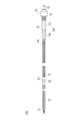
カテーテル60は、図3に示すように、先端側に配置された第1チューブ32と、第1チューブ32よりも基端側に配置された第2チューブ33と、第2チューブ33に挿入された第3チューブ34と、第1チューブ32と第2チューブ33を接続するコネクター45と、第1チューブ32の先端に配置された先端チップ41と、カテーテル60の基端に配置されたロックコネクター136と、を有している。
図3に示すように、送血用ルーメン61は、第3チューブ34の内腔に形成される。また、脱血用ルーメン62は、第1チューブ32の内腔、第2チューブ33の内腔、およびコネクター45の内腔に形成される。
医師等の術者は、カテーテル60を生体内に挿入する際、図2に示すダイレーター50を使用する。具体的には、ダイレーター50をカテーテル60の脱血用ルーメン62に挿通して、カテーテル60とダイレーター50と一体化させた状態でカテーテル組立体100を生体に挿入する。なお、カテーテル60の使用手順は後述する。
次に、カテーテル60の各部の構成を説明する。
図2および図3に示すように、カテーテル60は、カテーテル60の本体部分を構成するカテーテルチューブ31を有している。カテーテルチューブ31は、第1チューブ32と、第2チューブ33と、第3チューブ34と、を有している。
第1チューブ32は、第2チューブ33よりも伸縮性が高くなるように構成している。また、第1チューブ32は、ダイレーター50がカテーテルチューブ31に挿通されていない状態において、第2チューブ33よりも外径および内径が大きくなるように構成されている。
図3に示すように、第2チューブ33は、脱血用ルーメン62に連通する脱血孔64を備えている。脱血孔64は、例えば、平面視において楕円形状に形成できる。また、脱血孔64は、例えば、第2チューブ33の周方向の一部のみを切り開いて形成した孔(側孔)で構成できる。
第1チューブ32および第2チューブ33の長さ(軸方向の長さ)は、例えば、先端チップ41の各貫通孔46、47(図2、図3を参照)および第2チューブ33の脱血孔64のそれぞれを、脱血対象となる生体器官に配置するために十分な長さで形成できる。
カテーテル60は、例えば、ダイレーター50を挿入した状態で、第1チューブ32を比較的太い血管である下大静脈に配置でき、第2チューブ33を比較的細い血管である内頸静脈に配置できる。また、この際、第1チューブ32の先端に配置された先端チップ41の各貫通孔46、47は、脱血対象である下大静脈に配置でき、第2チューブ33の脱血孔64は、脱血対象である内頸静脈に配置できる。
上記のようにカテーテル60を配置(留置)して使用する場合、第1チューブ32の長さは、例えば、20~40cmに形成でき、第2チューブ33の長さは、例えば、20~30cmに形成できる。
図4に示すように、カテーテル60は、脱血用ルーメン62にダイレーター50が挿入されると、伸縮性の高い第1チューブ32が軸方向に伸長する。第1チューブ32は、軸方向への伸長に伴って外径および内径が小さくなる。この際、第1チューブ32の外径は、第2チューブ33の外径と略同一になる。医師等の術者は、第1チューブ32を軸方向に伸長させてその外径および内径を小さくした状態でカテーテル60を生体内に挿入することにより、カテーテル60の挿入を低侵襲に行うことができる。
また、カテーテル60を生体内に留置した後、ダイレーター50をカテーテル60から抜去すると、第1チューブ32は軸方向に伸長した状態から収縮して、外径および内径が大きくなる。前述したように、第1チューブ32は、比較的太い血管である下大静脈に配置される。このため、下大静脈に第1チューブ32を挿入した状態で、カテーテル60からダイレーター50を抜去すると、下大静脈の径に応じて第1チューブ32の外径が大きくなるように変形し、併せて第1チューブ32の内径が大きくなるように変形する。
ここで、第1チューブ32の脱血用ルーメン62の圧力損失については、第1チューブ32の内径を大きくすることによって、低減できる。そして、第1チューブ32の脱血用ルーメン62の圧力損失を低減することにより、循環回路を流れる血液の流量を増加できる。このため、血液の循環量を十分に得るためには、第1チューブ32の内径を大きくすることが好ましい。ただし、肉厚を一定に維持した状態で、第1チューブ32の内径を大きくした場合、第1チューブ32の外径が大きくなるため、生体へカテーテル60を挿入する際に患者の負担が大きくなり、低侵襲な手技の妨げとなる。
以上のような観点から、第1チューブ32の内径は、例えば、9~11mm、第2チューブ33の内径は、例えば、4~8mmとすることができる。また、第1チューブ32および第2チューブ33の肉厚は、例えば、0.4~0.5mmとすることができる。
図2および図3に示すように、カテーテル60にダイレーター50を挿入していない状態において、第1チューブ32の先端部は、軸方向の先端側に向かって徐々に細くなるテーパー部を有している。同様に、第1チューブ32の基端部は、軸方向の基端側に向かって徐々に細くなるテーパー部を有している。第1チューブ32の先端部の内径は、その先端側に配置された先端チップ41の内径と連続するように変化している。第1チューブ32の基端部の内径は、その基端側に配置されたコネクター45の内径と連続するように変化している。
第1チューブ32および第2チューブ33の各々は、例えば、交差するように編組されたワイヤーからなる補強体と、補強体を被覆するように設けられた樹脂層と、を有するように構成できる。
補強体に用いられるワイヤーは、例えば、公知の形状記憶金属や形状記憶樹脂等の形状記憶材料によって構成できる。形状記憶金属としては、例えば、チタン系(Ni-Ti、Ti-Pd、Ti-Nb-Sn等)や、銅系の合金を用いることができる。また、形状記憶樹脂としては、例えば、アクリル系樹脂、トランスイソプレンポリマー、ポリノルボルネン、スチレンーブタジエン共重合体、ポリウレタンを用いることができる。
第1チューブ32および第2チューブ33は、上記のように補強体に用いられるワイヤーが形状記憶材料によって構成されることにより、カテーテル60からダイレーター50を抜去した際に第1チューブ32が軸方向に変形する量(軸方向の収縮距離)と、カテーテル60にダイレーター50を挿通した際に第1チューブ32が軸方向に変形する量(軸方向の伸長距離)とが略同一になる。
図2に示すように、第1チューブ32の補強体を形成するワイヤーは、例えば、第2チューブ33の補強体を形成するワイヤーよりも、編み込みの間隔が疎となる(編み込みの隙間が大きくなる)ように形成できる。このように構成した場合、第1チューブ32は、第2チューブ33と比較して、柔軟性が高められるため、軸方向の伸縮性が向上する。
各チューブ32、33の補強体を形成するワイヤーの線径は、例えば、0.1mm~0.2mmである。
第1チューブ32の樹脂層は、例えば、第2チューブ33の樹脂層よりも、硬度の低い柔らかい材料によって構成できる。このように構成した場合、第1チューブ32は、第2チューブ33と比較して、柔軟性がより一層高められる。
各チューブ32、33の樹脂層は、例えば、塩化ビニル、シリコン、ポリエチレン、ナイロン、ウレタン、ポリウレタン、フッ素樹脂、熱可塑性エラストマー樹脂等、もしくはこれらの複合材料を用いて形成できる。
シリコン素材は、生体適合性が高く、素材自体も柔らかいため、血管壁や心臓壁を傷つけにくい特長がある。ポリエチレン素材は、柔らかく、且つ、圧力に耐える硬さを有している。さらに、ポリエチレン素材は、シリコン素材に匹敵する生体適合性を持つ。そして、ポリエチレン素材は、シリコンよりも硬く、細い血管に挿入し易い特長がある。また、ポリウレタン素材は、生体へ挿入後、柔らかくなる特長がある。各チューブ32、33の樹脂層を形成する材料としては、上記のような各素材の特徴を考慮した上で、適用可能な任意の材料を適宜選択することができる。
なお、樹脂層をポリウレタン素材で形成する場合、樹脂層に親水性のコーティングを施してもよい。上記のコーティングを施すことにより、チューブ表面が滑らかになり、血管挿入も行い易くなるため、血管壁を傷つけにくくなる。さらに、血液やタンパク質が付着しにくく、血栓の形成を防ぐことが期待できる。
各チューブ32、33を形成する方法は特に限定されないが、例えばディップコート(浸漬法)やインサート成形などにより形成することができる。
次に、第3チューブ34およびコネクター45について説明する。
図3に示すように、第3チューブ34は、第2チューブ33の脱血用ルーメン62とコネクター45の内腔45aに挿入されている。第3チューブ34の送血用ルーメン61の先端には、送血用ルーメン61に連通する送血孔63が形成されている。
第3チューブ34の長さ(軸方向の長さ)は、例えば、第2チューブ33の長さ(軸方向の長さ)よりも長く形成できる。第3チューブ34の長さは、例えば、15~25cmに形成できる。また、第3チューブ34の断面積は、例えば、11~15mm2に形成できる。
第3チューブ34は、例えば、塩化ビニル、シリコン、ポリエチレン、ナイロン、ウレタン、ポリウレタン、フッ素樹脂、熱可塑性エラストマー樹脂、もしくはこれらの複合材料を用いて形成できる。
図3に示すように、コネクター45は、第1チューブ32と第2チューブ33とを繋ぐ継手部材である。コネクター45は、例えば、一定の形状を保つ構造体(筐体)で形成できる。コネクター45は、例えば、硬質プラスチック等によって形成できる。
コネクター45は、筒状の本体部の両端側のそれぞれに接続部42、43が形成されている。コネクター45は、先端側の接続部42が第1チューブ32の基端側に差し込まれており、基端側の接続部43が第2チューブ33の先端側に差し込まれている。コネクター45の内腔45aは、第1チューブ32側の脱血用ルーメン62および第2チューブ33側の脱血用ルーメン62と連通する。
コネクター45は、コネクター45の周方向に沿う側面の一部に開口した側孔45bを有している。第3チューブ34の送血孔63は、コネクター45の側孔45bに臨むように配置されている。
次に、図5~図8を参照して、第3チューブ34が備える送血孔63について説明する。
第3チューブ34の送血孔63は、第3チューブ34の送血用ルーメン61を通過した血液をカテーテル60の外部へ流出する。具体的には、医師等の術者は、生体の送血対象(例えば、右心房)付近に送血孔63を配置した状態で、人工肺2により酸素化が行われた血液を送血孔63から流出させることにより、生体への送血を行う。
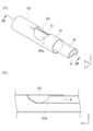
送血孔63は、図5に示す平面視において、基端側から先端側に向けて徐々に幅狭になる外形形状を有している。また、送血孔63は、第3チューブ34の周方向に沿う側面の一部を切り開いて形成した側孔で構成している。
図5および図7に示すように、送血孔63は、送血用ルーメン61に臨む基端側の側部63aが当該送血孔63の底部63bまで切り開かれている。換言すると、送血孔63の基端付近は、第3チューブ34の壁部(管壁)により囲まれておらず、送血孔63が形成された周方向の範囲に亘ってカテーテル60の外部に臨んで開口している。
なお、図7に示す軸方向に沿う断面において、カテーテル60の軸線に平行な直線c1と、送血孔63の基端側の開口面に平行な直線c2とがなす角度θ1は、例えば、90°または90°に近い角度に設定することができる。
図5および図6に示すように、送血孔63の先端側には、軸方向の先端側へ向けて凹状に湾曲した先端壁63cが形成されている。
先端壁63cは、送血孔63の先端側へ流出する血液の向きを所定の方向(例えば、右心房に送血孔63を配置する場合、三尖弁側の方向)に調整する。また、先端壁63cは、送血孔63の先端側へ直線的に流出する血液と接触して血流の勢いを弱めることにより、送血孔63の先端側へ勢い良く血液が流出するのを抑制することができる。
なお、先端壁63cの具体的な形状(例えば、図7に示す断面形状等)や軸方向の長さ等は特に限定されず、適宜変更することが可能である。
送血孔63から流出する血液の流れ(図5~図8において矢印Bで示す)について説明する。
図5および図6に示すように、第3チューブ34の送血用ルーメン61を流れる血液は、送血孔63に到達すると、第3チューブ34の管壁に遮られることなく、送血孔63の外側に広がるように分散する。このため、送血孔63から流出した血液が心臓壁等に接触した際に生じる衝撃を弱めることができる。また、血液は、送血孔63の先端側に形成された先端壁63cに到達すると、先端壁63cに沿って流れる。これにより、送血孔63の先端側から流出する血液の流出方向を所定の方向へ案内することができる。
図6および図8に示すように、第3チューブ34には、送血孔63の先端側と送血孔63の基端側との間に延在するリブ70を設けている。
リブ70は、例えば、図6に示すように軸方向に沿って略直線状に延在する棒状の部材で形成できる。リブ70は、カテーテル60を生体に挿入する際、送血孔63に生体組織(血管の管壁等)が引っ掛かるのを防止する機能を持つ。つまり、リブ70は、リブ70に接触した生体組織を支持することにより、送血孔63内に生体組織が落ち込むのを防止する。
リブ70は、例えば、図8に示すように、送血孔63の断面上において、幅方向(図8中の左右方向)の略中心位置に配置することができる。リブ70は、このような場所に配置されることにより、複数のリブを設けない場合においても、送血孔63に生体組織が引っ掛かるのを好適に防止できる。なお、リブ70の外面の断面形状は、例えば、生体組織への引っ掛かり等が生じるのをより好適に防止するために、外側に向けて凸状に湾曲した形状に形成することができる。
リブ70は、上述した効果が発揮される限り、形状(太さ、長さ、断面形状等)、個数、配置(直線状の配置、曲線状の配置等)、材質等は特に限定されない。また、リブ70は、第3チューブ34の一部により一体的に形成してもよいし、第3チューブ34とは別部材で形成してもよい。
次に、先端チップ41およびロックコネクター136について説明する。
図3に示すように、先端チップ41は、第1チューブ32の先端に配置される。先端チップ41は、先端側に向かって徐々に縮径された形状を備えている。
先端チップ41の内側には、ダイレーター50の先端に形成された平坦面50a(図2を参照)と当接する平坦な受け面48が形成されている。
図3に示すように、先端チップ41は、第1チューブ32の先端に挿入される基部49と、側面に設けられた複数の貫通孔46と、先端チップ41の先端に設けられた貫通孔47と、を有している。先端チップ41の各貫通孔46、47は、脱血対象から血液を脱血するための脱血用の孔として機能する。
先端チップ41は、例えば、硬質プラスチックにより形成することができる。比較的硬質な先端チップ41を第1チューブ32の先端部に固定することで、脱血時に第1チューブ32に作用する陰圧により第1チューブ32全体が潰れて閉塞してしまうのを効果的に防止することができる。
先端チップ41が備える各貫通孔46、47と、第2チューブ33が備える脱血孔64とは、生体の異なる脱血対象(例えば、内頸静脈と下大静脈)にそれぞれ配置することができる。このため、カテーテル60は、各貫通孔46、47と脱血孔64を介して脱血を効率的に行うことができる。また、仮に、先端チップ41が備える各貫通孔46、47または脱血孔64が血管壁等に吸着して塞がれてしまうようなことがあっても、塞がれていない他方の孔を介して脱血を行うことができるため、血液の体外循環を安定して行うことができる。
図3に示すように、ロックコネクター136は、第3チューブ34の送血用ルーメン61に連通する第1ロックコネクター137と、第2チューブ33の脱血用ルーメン62に連通する第2ロックコネクター138と、を有する。
ロックコネクター136は、第1ロックコネクター137が第2ロックコネクター138から分岐して形成されたY字状のYコネクターで構成している。第1ロックコネクター137には、送血チューブ12(図1参照)を接続でき、第2ロックコネクター138には、脱血チューブ11(図1参照)を接続できる。
次に、ダイレーター50について説明する。
図2に示すように、ダイレーター50は、軸方向に延在して設けられるダイレーターチューブ51と、ダイレーターチューブ51の基端が固定されるダイレーターハブ52と、ダイレーターハブ52の先端に設けられたネジリング53と、を有する。
ダイレーターチューブ51は、軸方向に延在し、比較的剛性の高い長尺体である。ダイレーターチューブ51の軸方向に沿う全長は、カテーテル60の軸方向に沿う全長よりも長く構成されている。
ダイレーターチューブ51は、ガイドワイヤー(図示せず)が挿通可能なガイドワイヤルーメン54を備えている。ダイレーターチューブ51は、ガイドワイヤーに導かれて、カテーテル60とともに生体に挿入される。ダイレーターチューブ51は、カテーテル60を生体に留置した後に、ダイレーターハブ52を基端側に引き抜くことでカテーテル60から抜去される。
図2に示すように、ダイレーターチューブ51の先端には、先端チップ41の受け面48と当接可能な平坦面50aを形成している。ダイレーターチューブ51は、比較的剛性が高く、かつ、先端側への押し込み力を先端チップ41に伝達可能なコシを備えている。このため、ダイレーターチューブ51は、平坦面50aを先端チップ41の受け面48に当接させた状態で先端側へ押し込まれることにより、比較的細径な血管を拡張しながらカテーテル60を所望の位置へ導くことができる。
図2に示すように、ダイレーター50のネジリング53は、内腔の内表面にネジ溝が設けられた雌ネジ部(図示せず)を有している。ネジリング53の雌ネジ部を、第2ロックコネクター138の雄ネジ部138Aに対してねじ込むことによって、ダイレーター50をカテーテル60に対して取り付け可能に構成されている。
次に、図9~図13を参照して、本実施形態に係るカテーテル60および比較例に係る各カテーテル160、260について実施した流出試験の結果(視認結果)を説明する。
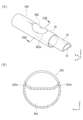
比較例1に係るカテーテル160の一部を図9(A)および図9(B)に示す。比較例1に係るカテーテル160は、送血孔163の基端付近の側部に側壁163aが形成されている。なお、カテーテル160には、リブ70を設けている。
比較例2に係るカテーテル260の一部を図10(A)および図10(B)に示す。比較例2に係るカテーテル260は、送血孔163の基端付近の側部に側壁263aが形成されている。また、側壁263aは、図10(B)に示すように、Z方向に立ち上がる形状で形成している。カテーテル260には、リブ70を設けていない。
図11は、本実施形態に係るカテーテル60の送血孔63から水を流出させた際の様子を撮影した写真である。水は、2L/minで第3チューブ34の送血用ルーメン61に流した。図11に示す写真は、カテーテル60の上面側(図5(B)に示す平面図を参照)から撮影したものである。図12は、比較例1に係るカテーテル160を上記と同条件で撮影した写真、図13は、比較例2に係るカテーテル260を上記と同条件で撮影した写真である。
図11に示すように、実施形態に係るカテーテル60の送血孔63から流出した水fは、カテーテル60の外側(図中の上下方向)に向けて分散する。これは、送血用ルーメン61と繋がる送血孔63の基端側に、水fの流出を妨げる側壁が形成されていないためであると考えられる。
一方、図12に示すように、比較例1に係るカテーテル160は、水fが送血孔163から流出する際、水fが先端側(図中の右側)へ向けて直線的に流出していることを確認できる。これは、送血孔163の基端付近に、水fの分散を阻害する側壁163aが形成されているためであると考えられる。また、図13に示すように、比較例2に係るカテーテル260は、比較例1に係るカテーテル160と同様に、送血孔263の基端付近に形成された側壁263aの影響により、水fが先端側(図中の右側)へ向けて直線的に流出していることを確認できる。
以上の結果から、本実施形態に係るカテーテル60は、送血孔63の基端付近の側部63aから液体(血液)を分散させて流出させることができ、心臓壁等に対する血液の衝突を和らげることが可能であることを確認できた。
次に、本実施形態に係るカテーテル60の作用効果を説明する。
本実施形態に係るカテーテル60は、軸方向に延在する送血用ルーメン61と、送血用ルーメン61の先端に連通する送血孔63と、を有しており、送血孔63は、送血用ルーメン61に臨む基端側の側部63aが当該送血孔63の底部63bまで切り開かれている。
上記のように構成したカテーテル60によれば、送血用ルーメン61を流れる血液は、送血用ルーメン61の先端に形成された送血孔63に到達すると、送血孔63の外側へ分散するように流出する。このため、カテーテル60は、送血孔63から流出した血液の衝突に伴う生体器官(血管壁や心臓壁等)への影響を低減することができる。
また、カテーテル60は、送血孔63の先端側に形成され軸方向の先端側へ向けて凹状に湾曲した先端壁63cを有する。このため、カテーテル60は、送血孔63の先端側へ流出する血液の向きを所定の方向に調整することができる。さらに、先端壁63cは、送血孔63の先端側へ直線的に流出する血液と接触して血流の勢いを弱めることにより、送血孔63の先端側へ勢い良く血液が流出するのを抑制できる。
また、カテーテル60は、送血孔63の先端側と送血孔63の基端側との間に延在し、送血孔63に対する生体組織の引っ掛かりを抑制するリブ70を有する。このため、カテーテル60は、生体に挿入される際、送血孔63に生体組織(血管の管壁等)が引っ掛かるのを防止でき、生体への挿入性が向上する。
以上、実施形態を通じて本発明に係るカテーテルを説明したが、本発明は実施形態において説明した構成のみに限定されることはなく、特許請求の範囲の記載に基づいて適宜変更することが可能である。
例えば、カテーテルから血液を流出させる送血孔の形状は、送血用ルーメンに臨む基端側の側部が当該送血孔の底部まで切り開かれている(送血孔の基端側に血液の流出を阻害する側壁が形成されていない)限り、特に制限されることはなく、具体的な形状(断面形状、外形形状等)、大きさ、位置等は特に制限されない。
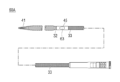
また、カテーテルとして、脱血および送血を同時に実施することが可能なダブルルーメンカテーテルを説明したが、例えば、図14に示すように、カテーテルは、送血を行う目的で使用される送血用カテーテル60Aとして構成することも可能である。なお、送血用カテーテル60Aの詳細な構造の説明は省略するが、例えば、第1チューブ32、第2チューブ33、コネクター45等により構成できる。この場合、送血孔63は、例えば、コネクター45に形成される孔(側孔等)により構成できる。
また、カテーテルが備えるカテーテルチューブは、第1チューブ、第2チューブ、第3チューブ等の複数のチューブにより形成せずに、例えば、一つのチューブで形成することも可能である。この場合、コネクター45の設置は適宜省略することが可能である。
本出願は、2017年6月9日に出願された日本国特許出願第2017-114672号に基づいており、その開示内容は、参照により全体として引用されている。
1 体外循環装置、
31 カテーテルチューブ、
32 第1チューブ、
33 第2チューブ、
34 第3チューブ、
41 先端チップ、
45 コネクター、
50 ダイレーター、
60、60A カテーテル、
61 送血用ルーメン、
62 脱血用ルーメン、
63 送血孔、
63a 側部、
63b 底部、
63c 先端壁、
64 脱血孔、
70 リブ、
100 カテーテル組立体。
31 カテーテルチューブ、
32 第1チューブ、
33 第2チューブ、
34 第3チューブ、
41 先端チップ、
45 コネクター、
50 ダイレーター、
60、60A カテーテル、
61 送血用ルーメン、
62 脱血用ルーメン、
63 送血孔、
63a 側部、
63b 底部、
63c 先端壁、
64 脱血孔、
70 リブ、
100 カテーテル組立体。
Claims (3)
- 軸方向に延在し血液を通すためのカテーテルであって、
前記軸方向に延在する送血用ルーメンと、
前記送血用ルーメンの先端に連通する送血孔と、を有し、
前記送血孔は、前記送血用ルーメンに臨む基端側の側部が当該送血孔の底部まで切り開かれている、カテーテル。 - 前記送血孔の先端側に形成され、前記軸方向の先端側へ向けて凹状に湾曲した先端壁を有する、請求項1に記載のカテーテル。
- 前記送血孔の先端側と前記送血孔の基端側との間に延在し、前記送血孔に対する生体組織の引っ掛かりを抑制するリブを有する、請求項1または請求項2に記載のカテーテル。
Priority Applications (2)
| Application Number | Priority Date | Filing Date | Title |
|---|---|---|---|
| JP2019523353A JP7054697B2 (ja) | 2017-06-09 | 2018-03-19 | カテーテル |
| US16/668,138 US11318281B2 (en) | 2017-06-09 | 2019-10-30 | Catheter for extracorporeal blood circulator |
Applications Claiming Priority (2)
| Application Number | Priority Date | Filing Date | Title |
|---|---|---|---|
| JP2017-114672 | 2017-06-09 | ||
| JP2017114672 | 2017-06-09 |
Related Child Applications (1)
| Application Number | Title | Priority Date | Filing Date |
|---|---|---|---|
| US16/668,138 Continuation US11318281B2 (en) | 2017-06-09 | 2019-10-30 | Catheter for extracorporeal blood circulator |
Publications (1)
| Publication Number | Publication Date |
|---|---|
| WO2018225331A1 true WO2018225331A1 (ja) | 2018-12-13 |
Family
ID=64566551
Family Applications (1)
| Application Number | Title | Priority Date | Filing Date |
|---|---|---|---|
| PCT/JP2018/010883 Ceased WO2018225331A1 (ja) | 2017-06-09 | 2018-03-19 | カテーテル |
Country Status (3)
| Country | Link |
|---|---|
| US (1) | US11318281B2 (ja) |
| JP (1) | JP7054697B2 (ja) |
| WO (1) | WO2018225331A1 (ja) |
Cited By (2)
| Publication number | Priority date | Publication date | Assignee | Title |
|---|---|---|---|---|
| WO2021118933A1 (en) * | 2019-12-09 | 2021-06-17 | The Cleveland Clinic Foundation | Apparatus and method for use of fluid flow device |
| JPWO2023073942A1 (ja) * | 2021-10-29 | 2023-05-04 |
Families Citing this family (1)
| Publication number | Priority date | Publication date | Assignee | Title |
|---|---|---|---|---|
| CN117015411A (zh) * | 2021-01-05 | 2023-11-07 | Tc1有限责任公司 | 用于体外膜式氧合系统的同轴插管 |
Citations (2)
| Publication number | Priority date | Publication date | Assignee | Title |
|---|---|---|---|---|
| JP2001104486A (ja) * | 1999-10-06 | 2001-04-17 | Nippon Sherwood Medical Industries Ltd | ダブルルーメンカテーテル |
| JP2007521913A (ja) * | 2004-02-12 | 2007-08-09 | ボストン サイエンティフィック サイムド,インコーポレイティド | 透析カテーテル先端部 |
Family Cites Families (5)
| Publication number | Priority date | Publication date | Assignee | Title |
|---|---|---|---|---|
| US4098275A (en) * | 1975-11-28 | 1978-07-04 | Dante Vincent Consalvo | Dual flow cannula set |
| US4134402A (en) * | 1976-02-11 | 1979-01-16 | Mahurkar Sakharam D | Double lumen hemodialysis catheter |
| US5976114A (en) * | 1998-04-30 | 1999-11-02 | Medtronic, Inc. | Aortic cannula with reduced velocity flow-through tip |
| US7850675B2 (en) * | 2004-07-20 | 2010-12-14 | Boston Scientific Scimed, Inc. | Reinforced venous access catheter |
| WO2007123156A1 (ja) | 2006-04-19 | 2007-11-01 | Asahi Kasei Kuraray Medical Co., Ltd. | 体外循環回路の圧力センサ |
-
2018
- 2018-03-19 JP JP2019523353A patent/JP7054697B2/ja active Active
- 2018-03-19 WO PCT/JP2018/010883 patent/WO2018225331A1/ja not_active Ceased
-
2019
- 2019-10-30 US US16/668,138 patent/US11318281B2/en active Active
Patent Citations (2)
| Publication number | Priority date | Publication date | Assignee | Title |
|---|---|---|---|---|
| JP2001104486A (ja) * | 1999-10-06 | 2001-04-17 | Nippon Sherwood Medical Industries Ltd | ダブルルーメンカテーテル |
| JP2007521913A (ja) * | 2004-02-12 | 2007-08-09 | ボストン サイエンティフィック サイムド,インコーポレイティド | 透析カテーテル先端部 |
Cited By (7)
| Publication number | Priority date | Publication date | Assignee | Title |
|---|---|---|---|---|
| WO2021118933A1 (en) * | 2019-12-09 | 2021-06-17 | The Cleveland Clinic Foundation | Apparatus and method for use of fluid flow device |
| CN115297921A (zh) * | 2019-12-09 | 2022-11-04 | 克利夫兰临床基金会 | 用于使用流体流动装置的设备和方法 |
| JP2023506622A (ja) * | 2019-12-09 | 2023-02-17 | ザ クリーヴランド クリニック ファウンデーション | 流体流通デバイスを用いるための装置及び方法 |
| JP7499333B2 (ja) | 2019-12-09 | 2024-06-13 | ザ クリーヴランド クリニック ファウンデーション | 流体流通デバイスを用いるための装置及び方法 |
| EP4559491A3 (en) * | 2019-12-09 | 2025-10-08 | The Cleveland Clinic Foundation | Apparatus and method for use of fluid flow device |
| JPWO2023073942A1 (ja) * | 2021-10-29 | 2023-05-04 | ||
| WO2023073942A1 (ja) * | 2021-10-29 | 2023-05-04 | 朝日インテック株式会社 | ダイレータキット |
Also Published As
| Publication number | Publication date |
|---|---|
| JP7054697B2 (ja) | 2022-04-14 |
| US20200069909A1 (en) | 2020-03-05 |
| US11318281B2 (en) | 2022-05-03 |
| JPWO2018225331A1 (ja) | 2020-04-09 |
Similar Documents
| Publication | Publication Date | Title |
|---|---|---|
| JP6887958B2 (ja) | 経皮カテーテル、経皮カテーテルの使用方法 | |
| JP6876710B2 (ja) | カテーテル | |
| US20150133723A1 (en) | Ventricular assist device and related methods | |
| US11318281B2 (en) | Catheter for extracorporeal blood circulator | |
| US11260159B2 (en) | Percutaneous catheter and percutaneous catheter assembly | |
| US20220401638A1 (en) | Percutaneous catheter | |
| JP6813570B2 (ja) | 経皮カテーテル | |
| JP2020089501A (ja) | 経皮カテーテル | |
| US20230347108A1 (en) | Stylet and catheter assembly | |
| JP6730430B2 (ja) | 経皮カテーテル組立体、経皮カテーテル、およびダイレーター | |
| US20220401696A1 (en) | Stylet for a percutaneous catheter | |
| JP7102350B2 (ja) | カテーテル | |
| JP7684489B2 (ja) | 経皮カテーテル | |
| JP2023032536A (ja) | シースおよび医療用組立体 | |
| WO2022168720A1 (ja) | 経皮カテーテル | |
| WO2021177165A1 (ja) | 経皮カテーテルおよび経皮カテーテルの使用方法 |
Legal Events
| Date | Code | Title | Description |
|---|---|---|---|
| 121 | Ep: the epo has been informed by wipo that ep was designated in this application |
Ref document number: 18813267 Country of ref document: EP Kind code of ref document: A1 |
|
| ENP | Entry into the national phase |
Ref document number: 2019523353 Country of ref document: JP Kind code of ref document: A |
|
| NENP | Non-entry into the national phase |
Ref country code: DE |
|
| 122 | Ep: pct application non-entry in european phase |
Ref document number: 18813267 Country of ref document: EP Kind code of ref document: A1 |