WO2018221108A1 - グラインダ - Google Patents
グラインダ Download PDFInfo
- Publication number
- WO2018221108A1 WO2018221108A1 PCT/JP2018/017230 JP2018017230W WO2018221108A1 WO 2018221108 A1 WO2018221108 A1 WO 2018221108A1 JP 2018017230 W JP2018017230 W JP 2018017230W WO 2018221108 A1 WO2018221108 A1 WO 2018221108A1
- Authority
- WO
- WIPO (PCT)
- Prior art keywords
- brushless motor
- grinder
- reactor
- motor
- substrate
- Prior art date
- Legal status (The legal status is an assumption and is not a legal conclusion. Google has not performed a legal analysis and makes no representation as to the accuracy of the status listed.)
- Ceased
Links
Images





Classifications
-
- B—PERFORMING OPERATIONS; TRANSPORTING
- B24—GRINDING; POLISHING
- B24B—MACHINES, DEVICES, OR PROCESSES FOR GRINDING OR POLISHING; DRESSING OR CONDITIONING OF ABRADING SURFACES; FEEDING OF GRINDING, POLISHING, OR LAPPING AGENTS
- B24B23/00—Portable grinding machines, e.g. hand-guided; Accessories therefor
- B24B23/02—Portable grinding machines, e.g. hand-guided; Accessories therefor with rotating grinding tools; Accessories therefor
-
- B—PERFORMING OPERATIONS; TRANSPORTING
- B25—HAND TOOLS; PORTABLE POWER-DRIVEN TOOLS; MANIPULATORS
- B25F—COMBINATION OR MULTI-PURPOSE TOOLS NOT OTHERWISE PROVIDED FOR; DETAILS OR COMPONENTS OF PORTABLE POWER-DRIVEN TOOLS NOT PARTICULARLY RELATED TO THE OPERATIONS PERFORMED AND NOT OTHERWISE PROVIDED FOR
- B25F5/00—Details or components of portable power-driven tools not particularly related to the operations performed and not otherwise provided for
Definitions
- the present invention relates to an AC drive grinder using a brushless motor as a drive source.
- An AC-driven electric tool using a brushless motor as a drive source includes a rectifier circuit such as a diode bridge, an inverter circuit that supplies a drive current to the motor, and a smoothing capacitor that smoothes the output current of the rectifier circuit.
- a rectifier circuit such as a diode bridge
- an inverter circuit that supplies a drive current to the motor
- a smoothing capacitor that smoothes the output current of the rectifier circuit.
- the smoothing capacitor is also enlarged (capacity increased) in order to allow a large ripple current.
- a reactor is required to prevent harmonics.
- the harmonic countermeasure reactor has a large size in order to allow a large motor current, and therefore the placement location becomes a problem in a power tool that is required to be downsized.
- the present invention has been made in view of such a situation, and an object of the present invention is to provide a grinder capable of suitably arranging a large smoothing capacitor and a reactor.
- One embodiment of the present invention is a grinder.
- This grinder A brushless motor, A motor housing that houses the brushless motor; A handle housing connected to the rear of the motor housing; An inverter circuit for supplying a drive current to the brushless motor; A rectifier circuit that converts alternating current into direct current and supplies the inverter circuit; A smoothing capacitor for smoothing the output current of the rectifier circuit; A reactor provided in a current path of the brushless motor, The smoothing capacitor and the reactor are arranged behind the brushless motor.
- the switching element which comprises the said inverter circuit may be arrange
- the reactor may be arranged in front of the switch.
- a fan that is rotated by the brushless motor The airflow generated by the fan may flow from the rear to the front inside the motor housing and the handle housing.
- a wind window is provided in the handle housing,
- the reactor may be arranged in front of the wind window.
- the switching element constituting the inverter circuit and the smoothing capacitor are provided on the substrate,
- the reactor may be provided behind the switching element and the smoothing capacitor.
- the smoothing capacitor and the reactor may be provided on the substrate.
- a substrate supported substantially perpendicular to the output shaft of the brushless motor behind the brushless motor;
- the smoothing capacitor and the control circuit are provided on the substrate;
- the reactor may be provided behind the smoothing capacitor and the control circuit.
- the handle housing has a handle guard;
- the smoothing capacitor may be provided in the handle guard.
- the grinder which can arrange
- FIG. 1 is a side sectional view of a grinder 1A according to Embodiment 1 of the present invention.
- the rear part expanded side sectional view of grinder 1A The circuit diagram of the grinder 1A.
- the rear part expanded side sectional view of the grinder 1B which concerns on Embodiment 2 of this invention.
- the rear part expanded side sectional view of grinder 1C concerning Embodiment 3 of the present invention.
- the rear part expanded side sectional view of grinder 1D concerning Embodiment 4 of the present invention.
- the rear part expanded side sectional view of the grinder 1E which concerns on Embodiment 5 of this invention.
- the rear part expanded side sectional view of grinder 1F concerning Embodiment 6 of the present invention.
- the rear part enlarged side sectional view of grinder 1G concerning Embodiment 7 of the present invention.
- FIG. 1 is a side sectional view of a grinder 1A according to Embodiment 1 of the present invention. With reference to FIG. 1, the vertical and front-rear directions are defined.
- FIG. 2 is a rear enlarged side sectional view of the grinder 1A.
- the grinder 1 ⁇ / b> A has an outer shell formed by a motor housing 2, a handle housing (tail cover) 3, and a gear case 4.
- a handle housing 3 is attached to the rear end portion of the motor housing 2, and a gear case 4 is attached to the front end portion of the motor housing 2.
- the motor housing 2 and the handle housing 3 are, for example, resin molded bodies.
- the gear case 4 is made of metal such as aluminum.
- a power cord 9 for connecting to an external AC power supply 50 extends from the rear end of the handle housing 3.
- a filter substrate 10 is provided at the rear part in the handle housing 3.
- the handle housing 3 constitutes the handle of the electric tool 1.
- a trigger 7 is supported at the lower portion of the handle housing 3 so as to be swingable (pivotable).
- the trigger 7 is an operation unit for the user to switch on / off of the main switch 11 provided in the current path of the motor 6.
- the main switch 11 is preferably a mechanical contact switch, is housed in the handle housing 3 and is located above the trigger 7.
- a reactor L2 and an electric field capacitor C2 are provided at a position in front of the main switch 11.
- the front-rear direction positions of the reactor L2 and the electric field capacitor C2 are substantially equal to each other.
- the electric field capacitor C2 is for smoothing and is a high capacity type that can tolerate a large ripple current.
- the reactor L2 is a large-sized type that is for harmonic measures and can tolerate a large motor current.
- the motor housing 2 accommodates the motor 6 and accommodates a first substrate (drive substrate) 30 at the rear of the motor 6.
- the motor 6 is an inner rotor type brushless motor.
- the first substrate 30 is supported substantially perpendicular to the output shaft 6a of the motor 6, and is mounted with a rectifier diode bridge 15 and an inverter circuit 47 (switching elements Q1 to Q6 in FIG. 3) for supplying a drive current to the motor 6.
- a fan 13 that rotates integrally with the output shaft 6 a is provided in front of the motor 6.
- the airflow (cooling air) generated by the fan 13 enters the handle housing 3 from the wind windows provided on the left and right sides of the handle housing 3 (located on the front side and the back side of the reactor L2 in FIG.
- the gear case 4 houses a speed reduction mechanism 5 as a rotation transmission mechanism.
- the speed reduction mechanism 5 is a combination of a pair of bevel gears.
- the speed reduction mechanism 5 reduces the rotation of the motor 6 and converts it 90 degrees to transmit it to the spindle 8.
- a grindstone 8a as a rotating tool (tip tool) is provided at the lower end of the spindle 8 so as to be integrally rotatable. Since the mechanical configuration and operation from the rotation of the motor 6 to the rotation of the grindstone 8a are well known, further detailed description is omitted.
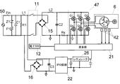
- FIG. 3 is a circuit diagram of the grinder 1A.
- the circuit of FIG. 3 is common to each embodiment described later.
- the AC power supply 50 is an external AC power supply such as a commercial power supply.
- a filter circuit provided on the filter substrate 10 is connected to the AC power supply 50.
- the filter circuit includes a fuse Fin, a varistor Z1, a pattern fuse F1, a capacitor C1, a resistor R1, and a choke coil L1 mounted on the filter substrate 10.
- the fuse Fin is for protection when the switching elements Q1 to Q6 are short-circuited.
- the varistor Z1 is for absorbing surge voltage.
- the pattern fuse F1 has a role of preventing a short circuit between lines when the varistor Z1 is activated.
- the capacitor C1 and the choke coil L1 are for removing noise between lines.
- the resistor R1 is a discharge resistor of the capacitor C1.
- a main switch 11 is provided between the output side of the filter circuit and the input side of the diode bridge 15.
- the main switch 11 is a two-pole switch, and is connected between one output terminal of the filter circuit and one input terminal of the diode bridge 15, and between the other output terminal of the filter circuit and the other input terminal of the diode bridge 15. Both sides can be opened and closed.
- the diode bridge 15 as a rectifier circuit performs full-wave rectification on the output voltage of the filter circuit input via the main switch 11, converts it into direct current, and supplies it to the inverter circuit 47.
- the electrolytic capacitor C ⁇ b> 2 is for absorbing surge and smoothing, and is provided between the output terminals of the diode bridge 15.
- Reactor L2 is for harmonic countermeasures and is connected to the current path of motor 6 and to the side of diode bridge 15 of electrolytic capacitor C2.
- the resistor Rs is a detection resistor for detecting the current flowing through the motor 6 and is provided in the current path of the motor 6.
- the diode bridge 15, the inverter circuit 47, and the resistor Rs are provided on the first substrate 30 in FIG.
- the inverter circuit 47 includes switching elements Q1 to Q6 such as IGBTs and FETs connected in a three-phase bridge, and performs a switching operation in accordance with the control of the arithmetic unit 21 as a control unit, so that the stator coils (U, V, W of the motor 6) A drive current is supplied to each winding).
- the computing unit 21 detects the current of the motor 6 based on the voltage across the resistor Rs.
- the computing unit 21 detects the rotational position (rotor rotational position) of the motor 6 based on the output voltages of the plurality of Hall elements (magnetic sensors) 42.
- the arithmetic unit 21 controls driving and braking of the motor 6 according to on / off of the electronic switch 12 that is integrally provided in the main switch 11 and interlocks with the operation of the trigger 7, for example. Specifically, when the electronic switch 12 is turned on by operating the trigger 7, the calculation unit 21 performs switching control (for example, PWM control) on the switching elements Q 1 to Q 6 and controls driving of the motor 6. When the electronic switch 12 is turned off by the operation of the trigger 7, the arithmetic unit 21 may perform control (brake control) for applying a braking force to the motor 6 or may turn off the switching elements Q1 to Q6.
- the brake control is performed by, for example, turning on or off at least one of the lower arm side switching elements Q4 to Q6 continuously or intermittently while keeping the upper arm side switching elements Q1 to Q3 of the inverter circuit 47 off. This is control for generating power.
- the IPD circuit 22 is a circuit configured by an IPD element, a capacitor, or the like that is an intelligent power device, and a voltage rectified and smoothed by the diode bridge 16 and an electrolytic capacitor C3 for surge absorption, for example. This is a DC-DC switching power supply circuit that steps down to about 18V.
- the IPD circuit 22 is an integrated circuit and has an advantage of low power consumption and energy saving.
- the output voltage of the IPD circuit 22 is further stepped down to, for example, about 5 V by the regulator 26 and is supplied to the arithmetic unit 21 as an operating voltage (power supply voltage Vcc).
- the reactor L2 and the electrolytic capacitor C2 are provided behind the motor 6 and in front of the main switch 11, and wiring can be easily performed while suppressing an increase in size.
- FIG. 4 is a rear enlarged side sectional view of a grinder 1B according to Embodiment 2 of the present invention.
- the reactor L ⁇ b> 2 is provided on the first substrate 30 together with the inverter circuit 47.
- the electrolytic capacitor C2 is provided in the handle housing 3, and is located in front of the main switch 11 and behind the reactor L2. This embodiment also facilitates wiring while suppressing an increase in size. Further, since the reactor L2 is moved from the handle housing 3 into the motor housing 2, a large capacitor can be disposed in the handle housing 3.
- FIG. 5 is a rear enlarged side sectional view of a grinder 1C according to Embodiment 3 of the present invention.
- the reactor L2 and the electrolytic capacitor C2 are provided on the first substrate 30.
- An inverter circuit 47 is provided on the third substrate 40 provided at the rear end of the stator of the motor 6.
- a second substrate 20 is provided at the front portion in the handle housing 3.
- the second substrate 20 is provided with a diode bridge 16, an electrolytic capacitor C3, a calculation unit 21, an IPD circuit 22, a regulator 26, and the like. This embodiment also facilitates wiring while suppressing an increase in size.
- the reactor L2 and the electrolytic capacitor C2 are mounted on the first substrate 30 by securing the circuit mounting area of the first substrate 30 as much as the inverter circuit 47 is moved to the rear end of the motor 6. Since no heat generating element can be arranged around the second substrate 20, the influence of heat received by the arithmetic unit 21 can be reduced.
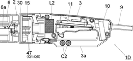
- FIG. 6 is a rear enlarged side sectional view of a grinder 1D according to Embodiment 4 of the present invention.
- the grinder 1D is different from the grinder 1A of the first embodiment shown in FIG. 2 in that the handle housing 3 has a handle card 3a and an electrolytic capacitor C2 is provided in the handle card 3a.
- the handle card 3 a extends in the front-rear direction so as to face the trigger 7, and has a function of protecting the operator's hand holding the handle housing 3.
- an electrolytic capacitor C2 having a higher capacity can be provided by utilizing the space in the handle card 3a.
- This embodiment also facilitates wiring while suppressing an increase in size.
- the inside of the handle guard 3a can be used as a wiring space, a space for wiring secured around the main switch 11 is deleted, and the grip portion of the handle housing 3 is made smaller in diameter so that it can be easily gripped. Can do.
- FIG. 7 is a rear enlarged side sectional view of a grinder 1E according to Embodiment 5 of the present invention.
- the handle housing 3 has a handle card 3a as in the configuration of FIG. 6, and is different in that an electrolytic capacitor C2 is provided in the handle card 3a. Matches in other respects.
- This embodiment also facilitates wiring while suppressing an increase in size.
- the handle housing 3 can be made compact by eliminating the element housing space in the handle housing 3.
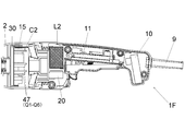
- FIG. 8 is a rear enlarged side sectional view of a grinder 1F according to Embodiment 6 of the present invention.
- the diode bridge 15, the electrolytic capacitor C2, and the inverter circuit 47 are provided on the first substrate 30.
- the reactor L2 and the second substrate 20 are provided in the front part in the handle housing 3 (behind the electrolytic capacitor C2 and the inverter circuit 47 and in front of the main switch 11). This embodiment also facilitates wiring while suppressing an increase in size.
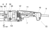
- FIG. 9 is a rear enlarged side sectional view of a grinder 1G according to Embodiment 7 of the present invention.
- the electrolytic capacitor C2 is provided on the first substrate 30, the second substrate 20 is provided at a position in the front-rear direction substantially equal to the electrolytic capacitor C2, and the reactor L2 is disposed in the front portion (the electrolytic capacitor C2 and the first capacitor It is provided behind the two substrates 20 and in front of the main switch 11.
- An inverter circuit 47 is provided on the third substrate 40 provided at the rear end of the stator of the motor 6. This embodiment also facilitates wiring while suppressing an increase in size.
Landscapes
- Engineering & Computer Science (AREA)
- Mechanical Engineering (AREA)
- Finish Polishing, Edge Sharpening, And Grinding By Specific Grinding Devices (AREA)
- Portable Power Tools In General (AREA)
Abstract
大型の平滑コンデンサ及びリアクトルを好適に配置可能なグラインダを提供する。グラインダ(1A)は、ブラシレスモータ(6)と、ブラシレスモータ(6)を収容するモータハウジング(2)と、モータハウジング(2)の後方に接続されるハンドルハウジング(3)と、ブラシレスモータ(6)に駆動電流を供給するインバータ回路(47)と、交流を直流に変換してインバータ回路(47)に供給するダイオードブリッジ(15)と、ダイオードブリッジ(15)の出力電流を平滑する電界コンデンサ(C2)と、ブラシレスモータ(6)の電流経路に設けられたリアクトル(L2)と、を備え、電界コンデンサ(C2)及びリアクトル(L2)が、ブラシレスモータ(6)よりも後方に配置されている。
Description
本発明は、ブラシレスモータを駆動源とする交流駆動のグラインダに関する。
ブラシレスモータを駆動源とする交流駆動の電動工具は、ダイオードブリッジ等の整流回路、モータに駆動電流を供給するインバータ回路、及び整流回路の出力電流を平滑する平滑コンデンサ、を備える。
大型のグラインダ等の高出力工具においては、大きなリプル電流を許容するために、平滑コンデンサも大型化(高容量化)する。高容量の平滑コンデンサを設ける場合、高調波対策のためにリアクトルが必要となる。高調波対策のリアクトルは、大きなモータ電流を許容するためにサイズが大きいため、小型化が求められる電動工具においては配置場所が課題となる。
本発明はこうした状況を認識してなされたものであり、その目的は、大型の平滑コンデンサ及びリアクトルを好適に配置可能なグラインダを提供することにある。
本発明のある態様は、グラインダである。このグラインダは、
ブラシレスモータと、
前記ブラシレスモータを収容するモータハウジングと、
前記モータハウジングの後方に接続されるハンドルハウジングと、
前記ブラシレスモータに駆動電流を供給するインバータ回路と、
交流を直流に変換して前記インバータ回路に供給する整流回路と、
前記整流回路の出力電流を平滑する平滑コンデンサと、
前記ブラシレスモータの電流経路に設けられたリアクトルと、を備え、
前記平滑コンデンサ及び前記リアクトルが、前記ブラシレスモータよりも後方に配置されている。
ブラシレスモータと、
前記ブラシレスモータを収容するモータハウジングと、
前記モータハウジングの後方に接続されるハンドルハウジングと、
前記ブラシレスモータに駆動電流を供給するインバータ回路と、
交流を直流に変換して前記インバータ回路に供給する整流回路と、
前記整流回路の出力電流を平滑する平滑コンデンサと、
前記ブラシレスモータの電流経路に設けられたリアクトルと、を備え、
前記平滑コンデンサ及び前記リアクトルが、前記ブラシレスモータよりも後方に配置されている。
前記インバータ回路を構成するスイッチング素子が、前記ブラシレスモータよりも後方に配置されていてもよい。
前記ハンドルハウジングに収容され、前記ブラシレスモータの電流経路に設けられたスイッチと、
前記ハンドルハウジングに支持され、前記スイッチのオンオフを切り替えるためのトリガと、を備え、
前記リアクトルが、前記スイッチよりも前方に配置されてもよい。
前記ハンドルハウジングに支持され、前記スイッチのオンオフを切り替えるためのトリガと、を備え、
前記リアクトルが、前記スイッチよりも前方に配置されてもよい。
前記ブラシレスモータによって回転するファンを備え、
前記ファンの発生する気流が、前記モータハウジング及び前記ハンドルハウジングの内側において後方から前方に流れてもよい。
前記ファンの発生する気流が、前記モータハウジング及び前記ハンドルハウジングの内側において後方から前方に流れてもよい。
前記ハンドルハウジングに風窓が設けられ、
前記リアクトルが、前記風窓よりも前方に配置されてもよい。
前記リアクトルが、前記風窓よりも前方に配置されてもよい。
前記ブラシレスモータよりも後方において前記ブラシレスモータの出力軸と略垂直に支持された基板を備え、
前記インバータ回路を構成するスイッチング素子及び前記平滑コンデンサが、前記基板に設けられ、
前記リアクトルが、前記スイッチング素子及び前記平滑コンデンサよりも後方に設けられてもよい。
前記インバータ回路を構成するスイッチング素子及び前記平滑コンデンサが、前記基板に設けられ、
前記リアクトルが、前記スイッチング素子及び前記平滑コンデンサよりも後方に設けられてもよい。
前記ブラシレスモータよりも後方において前記ブラシレスモータの出力軸と略垂直に支持された基板を備え、
前記平滑コンデンサ及び前記リアクトルが、前記基板に設けられてもよい。
前記平滑コンデンサ及び前記リアクトルが、前記基板に設けられてもよい。
前記ブラシレスモータよりも後方において前記ブラシレスモータの出力軸と略垂直に支持された基板を備え、
前記平滑コンデンサ及び制御回路が前記基板に設けられ、
前記リアクトルが、前記平滑コンデンサ及び制御回路よりも後方に設けられてもよい。
前記平滑コンデンサ及び制御回路が前記基板に設けられ、
前記リアクトルが、前記平滑コンデンサ及び制御回路よりも後方に設けられてもよい。
前記ハンドルハウジングがハンドルガードを有し、
前記ハンドルガード内に前記平滑コンデンサが設けられてもよい。
前記ハンドルガード内に前記平滑コンデンサが設けられてもよい。
なお、以上の構成要素の任意の組合せ、本発明の表現を方法やシステムなどの間で変換したものもまた、本発明の態様として有効である。
本発明によれば、大型の平滑コンデンサ及びリアクトルを好適に配置可能なグラインダを提供することができる。
以下、図面を参照しながら本発明の好適な実施の形態を詳述する。なお、各図面に示される同一または同等の構成要素、部材等には同一の符号を付し、適宜重複した説明は省略する。また、実施の形態は発明を限定するものではなく例示であり、実施の形態に記述されるすべての特徴やその組み合わせは必ずしも発明の本質的なものであるとは限らない。
(実施の形態1) 図1は、本発明の実施の形態1に係るグラインダ1Aの側断面図である。図1により、上下及び前後方向を定義する。図2は、グラインダ1Aの後部拡大側断面図である。グラインダ1Aは、モータハウジング2、ハンドルハウジング(テールカバー)3、及びギヤケース4により、外殻が形成される。モータハウジング2の後端部にハンドルハウジング3が取り付けられ、モータハウジング2の前端部にギヤケース4が取り付けられる。モータハウジング2及びハンドルハウジング3は、例えば樹脂成形体である。ギヤケース4は、例えばアルミ等の金属製である。
ハンドルハウジング3の後端部からは、外部の交流電源50(図3)に接続するための電源コード9が延びる。ハンドルハウジング3内の後部には、フィルタ基板10が設けられる。ハンドルハウジング3は、電動工具1のハンドルを構成する。ハンドルハウジング3の下部には、トリガ7が揺動(回動)可能に支持される。トリガ7は、モータ6の電流経路に設けられたメインスイッチ11のオンオフを使用者が切り替えるための操作部である。メインスイッチ11は、好ましくは機械式の接点スイッチであり、ハンドルハウジング3内に収容され、トリガ7の上方に位置する。ハンドルハウジング3内には、メインスイッチ11の前方となる位置に、リアクトルL2及び電界コンデンサC2が設けられる。リアクトルL2及び電界コンデンサC2の前後方向位置は互いに略等しい。電界コンデンサC2は、平滑用であり、大きなリプル電流を許容可能な高容量タイプである。リアクトルL2は、高調波対策用であり、大きなモータ電流を許容可能な大型タイプである。
モータハウジング2は、モータ6を収容すると共に、モータ6の後部に第1基板(駆動基板)30を収容する。モータ6は、インナーロータ型のブラシレスモータである。第1基板30は、モータ6の出力軸6aと略垂直に支持され、整流用のダイオードブリッジ15及びモータ6に駆動電流を供給するインバータ回路47(図3のスイッチング素子Q1~Q6)を搭載する。モータ6の前方には、出力軸6aと一体に回転するファン13が設けられる。ファン13の発生する気流(冷却風)は、ハンドルハウジング3の左右に設けられた風窓(図2においてリアクトルL2の紙面手前及び奥側にそれぞれ位置する)からハンドルハウジング3内に入り、リアクトルL2及び電解コンデンサC2、ダイオードブリッジ15及びインバータ回路47、並びにモータ6を冷却し、ギヤケース4の風窓から前方に排気される。ギヤケース4内には、回転伝達機構としての減速機構5が収容される。減速機構5は、一対のベベルギアを組み合わせたものであり、モータ6の回転を減速すると共に90度変換してスピンドル8に伝達する。スピンドル8の下端部には回転具(先端工具)としての砥石8aが一体回転可能に設けられる。モータ6の回転から砥石8aの回転に至るまでの機械的な構成及び動作は周知なので、これ以上の詳細な説明は省略する。
図3は、グラインダ1Aの回路図である。図3の回路は、後述の各実施の形態においても共通である。交流電源50は、商用電源等の外部交流電源である。交流電源50には、フィルタ基板10に設けられたフィルタ回路が接続される。フィルタ回路は、フィルタ基板10に搭載された、ヒューズFin、バリスタZ1、パターンヒューズF1、コンデンサC1、抵抗R1、及びチョークコイルL1を含む。ヒューズFinは、スイッチング素子Q1~Q6が短絡した場合の保護用である。バリスタZ1は、サージ電圧吸収用である。パターンヒューズF1は、バリスタZ1が働いた場合に線間がショートするのを防止する役割を持つ。コンデンサC1及びチョークコイルL1は、線間のノイズ除去用である。抵抗R1は、コンデンサC1の放電抵抗である。
前述のフィルタ回路の出力側とダイオードブリッジ15の入力側との間に、メインスイッチ11が設けられる。メインスイッチ11は、2極スイッチであり、フィルタ回路の一方の出力端子とダイオードブリッジ15の一方の入力端子との間、及びフィルタ回路の他方の出力端子とダイオードブリッジ15の他方の入力端子との間、の双方を開閉できるようになっている。整流回路としてのダイオードブリッジ15は、メインスイッチ11を介して入力される前述のフィルタ回路の出力電圧を、全波整流して直流に変換し、インバータ回路47に供給する。電解コンデンサC2は、サージ吸収用かつ平滑用であり、ダイオードブリッジ15の出力端子間に設けられる。リアクトルL2は、高調波対策用であり、モータ6の電流経路であって電解コンデンサC2のダイオードブリッジ15側に接続される。抵抗Rsは、モータ6に流れる電流を検出するための検出抵抗であり、モータ6の電流経路に設けられる。ダイオードブリッジ15、インバータ回路47、及び抵抗Rsは、図1の第1基板30に設けられる。
インバータ回路47は、三相ブリッジ接続されたIGBTやFET等のスイッチング素子Q1~Q6を含み、制御部としての演算部21の制御に従ってスイッチング動作し、モータ6のステータコイル(U,V,Wの各巻線)に駆動電流を供給する。抵抗Rsの両端間の電圧により、演算部21はモータ6の電流を検出する。また、演算部21は、複数のホール素子(磁気センサ)42の出力電圧により、モータ6の回転位置(ロータ回転位置)を検出する。演算部21は、例えばメインスイッチ11の内部に一体的に設けられてトリガ7の操作に連動する電子スイッチ12のオンオフに応じて、モータ6の駆動及び制動を制御する。具体的には、演算部21は、トリガ7の操作により電子スイッチ12がオンされると、スイッチング素子Q1~Q6をスイッチング制御(例えばPWM制御)し、モータ6の駆動を制御する。演算部21は、トリガ7の操作により電子スイッチ12がオフされると、モータ6に制動力を与える制御(ブレーキ制御)を行ってもよいし、スイッチング素子Q1~Q6をオフしてもよい。ブレーキ制御は、例えば、インバータ回路47の上アーム側スイッチング素子Q1~Q3をオフに維持しながら下アーム側スイッチング素子Q4~Q6の少なくともいずれかを連続的ないし断続的にオンすることで、電気制動力を発生させる制御である。
整流回路としてのもう1つのダイオードブリッジ16は、メインスイッチ11を介さずに入力される前述のフィルタ回路の出力電圧を、全波整流して直流に変換する。電解コンデンサC3は、サージ吸収用であり、ダイオードブリッジ16の出力端子間に設けられる。ダイオードブリッジ16の出力側には、IPD回路22が設けられる。IPD回路22は、インテリジェント・パワー・デバイス(Intelligent Power Device)であるIPD素子やコンデンサ等により構成された回路であり、ダイオードブリッジ16及びサージ吸収用の電解コンデンサC3によって整流、平滑された電圧を例えば約18Vに降圧するDC-DCスイッチング電源回路である。IPD回路22は、集積回路であり、消費電力が小さく省エネルギーであるというメリットがある。IPD回路22の出力電圧は、レギュレータ26によって例えば約5Vに更に降圧され、演算部21に動作電圧(電源電圧Vcc)として供給される。
本実施の形態によれば、モータ6の後方かつメインスイッチ11の前方にリアクトルL2及び電解コンデンサC2を設けており、大型化を抑制しながら配線も容易にできる。
(実施の形態2) 図4は、本発明の実施の形態2に係るグラインダ1Bの後部拡大側断面図である。グラインダ1Bでは、リアクトルL2は、インバータ回路47と共に第1基板30に設けられる。電解コンデンサC2は、ハンドルハウジング3内に設けられ、メインスイッチ11の前方かつリアクトルL2の後方に位置する。本実施の形態も、大型化を抑制しながら配線も容易にできる。また、リアクトルL2をハンドルハウジング3からモータハウジング2内に移したので、ハンドルハウジング3内により大型のコンデンサを配置することが可能となる。
(実施の形態3) 図5は、本発明の実施の形態3に係るグラインダ1Cの後部拡大側断面図である。グラインダ1Cでは、リアクトルL2及び電解コンデンサC2が、第1基板30に設けられる。また、モータ6のステータ後端部に設けられた第3基板40に、インバータ回路47が設けられる。ハンドルハウジング3内の前部には、第2基板20が設けられる。第2基板20には、ダイオードブリッジ16、電解コンデンサC3、演算部21、IPD回路22、及びレギュレータ26等が設けられる。本実施の形態も、大型化を抑制しながら配線も容易にできる。また、インバータ回路47をモータ6の後端部に移した分、第1基板30の回路搭載面積を確保したことでリアクトルL2及び電解コンデンサC2を第1基板30に搭載し、ハンドルハウジング3内の第2基板20の周囲には発熱素子を配置しないようにできるので、演算部21が受ける熱の影響を低減することができる。
(実施の形態4) 図6は、本発明の実施の形態4に係るグラインダ1Dの後部拡大側断面図である。グラインダ1Dは、図2に示す実施の形態1のグラインダ1Aと比較して、ハンドルハウジング3がハンドルカード3aを有し、ハンドルカード3a内に電解コンデンサC2が設けられる点で相違し、その他の点で一致する。ハンドルカード3aは、トリガ7と対向するように前後方向に延び、ハンドルハウジング3を把持する作業者の手を保護する働きを有する。本実施形態においては、ハンドルカード3a内のスペースを利用することで、より高容量の電解コンデンサC2を設けることができる。本実施の形態も、大型化を抑制しながら配線も容易にできる。また、ハンドルガード3a内を配線空間として利用できるので、メインスイッチ11の周辺に確保される配線のための空間を削除し、ハンドルハウジング3の把持部分をより小径にして把持しやすい構成とすることができる。
(実施の形態5) 図7は、本発明の実施の形態5に係るグラインダ1Eの後部拡大側断面図である。図4に示す実施の形態2のグラインダ1Bと比較して、図6の構成と同様にハンドルハウジング3がハンドルカード3aを有し、ハンドルカード3a内に電解コンデンサC2が設けられる点で相違し、その他の点で一致する。本実施の形態も、大型化を抑制しながら配線も容易にできる。また、ハンドルハウジング3内の素子収容空間を無くした分ハンドルハウジング3を小型に形成できる。
(実施の形態6) 図8は、本発明の実施の形態6に係るグラインダ1Fの後部拡大側断面図である。グラインダ1Fでは、ダイオードブリッジ15、電解コンデンサC2、及びインバータ回路47が第1基板30に設けられる。ハンドルハウジング3内の前部(電解コンデンサC2及びインバータ回路47よりも後方かつメインスイッチ11の前方)に、リアクトルL2及び第2基板20が設けられる。本実施の形態も、大型化を抑制しながら配線も容易にできる。
(実施の形態7) 図9は、本発明の実施の形態7に係るグラインダ1Gの後部拡大側断面図である。グラインダ1Gでは、電解コンデンサC2が第1基板30に設けられ、第2基板20が電解コンデンサC2と略等しい前後方向位置に設けられ、リアクトルL2がハンドルハウジング3内の前部(電解コンデンサC2及び第2基板20よりも後方かつメインスイッチ11の前方)に設けられる。また、モータ6のステータ後端部に設けられた第3基板40に、インバータ回路47が設けられる。本実施の形態も、大型化を抑制しながら配線も容易にできる。
以上、実施の形態を例に本発明を説明したが、実施の形態の各構成要素や各処理プロセスには請求項に記載の範囲で種々の変形が可能であることは当業者に理解されるところである。
1A~1E…グラインダ、2…モータハウジング、3…ハンドルハウジング(テールカバー)、4…ギヤケース、5…減速機構(回転伝達機構)、6…モータ、6a…出力軸、7…トリガ、8…スピンドル、8a…砥石、9…電源コード、10…フィルタ基板、11…メインスイッチ(接点スイッチ)、13…ファン、15,16…ダイオードブリッジ、20…第2基板、21…演算部(制御部)、22…IPD回路、26…レギュレータ、30…第1基板(駆動基板)、42…ホール素子(磁気センサ)、50…交流電源
Claims (9)
- ブラシレスモータと、
前記ブラシレスモータを収容するモータハウジングと、
前記モータハウジングの後方に接続されるハンドルハウジングと、
前記ブラシレスモータに駆動電流を供給するインバータ回路と、
交流を直流に変換して前記インバータ回路に供給する整流回路と、
前記整流回路の出力電流を平滑する平滑コンデンサと、
前記ブラシレスモータの電流経路に設けられたリアクトルと、を備え、
前記平滑コンデンサ及び前記リアクトルが、前記ブラシレスモータよりも後方に配置されている、グラインダ。 - 前記インバータ回路を構成するスイッチング素子が、前記ブラシレスモータよりも後方に配置されている、請求項1に記載のグラインダ。
- 前記ハンドルハウジングに収容され、前記ブラシレスモータの電流経路に設けられたスイッチと、
前記ハンドルハウジングに支持され、前記スイッチのオンオフを切り替えるためのトリガと、を備え、
前記リアクトルが、前記スイッチよりも前方に配置されている、請求項1又は2に記載のグラインダ。 - 前記ブラシレスモータによって回転するファンを備え、
前記ファンの発生する気流が、前記モータハウジング及び前記ハンドルハウジングの内側において後方から前方に流れる、請求項1から3のいずれか一項に記載のグラインダ。 - 前記ハンドルハウジングに風窓が設けられ、
前記リアクトルが、前記風窓よりも前方に配置されている、請求項4に記載のグラインダ。 - 前記ブラシレスモータよりも後方において前記ブラシレスモータの出力軸と略垂直に支持された基板を備え、
前記インバータ回路を構成するスイッチング素子及び前記平滑コンデンサが、前記基板に設けられ、
前記リアクトルが、前記スイッチング素子及び前記平滑コンデンサよりも後方に設けられている、請求項1から5のいずれか一項に記載のグラインダ。 - 前記ブラシレスモータよりも後方において前記ブラシレスモータの出力軸と略垂直に支持された基板を備え、
前記平滑コンデンサ及び前記リアクトルが、前記基板に設けられている、請求項1から5のいずれか一項に記載のグラインダ。 - 前記ブラシレスモータよりも後方において前記ブラシレスモータの出力軸と略垂直に支持された基板を備え、
前記平滑コンデンサ及び制御回路が前記基板に設けられ、
前記リアクトルが、前記平滑コンデンサ及び制御回路よりも後方に設けられている、請求項1から5のいずれか一項に記載のグラインダ。 - 前記ハンドルハウジングがハンドルガードを有し、
前記ハンドルガード内に前記平滑コンデンサが設けられている、請求項1から5のいずれか一項に記載のグラインダ。
Priority Applications (1)
| Application Number | Priority Date | Filing Date | Title |
|---|---|---|---|
| JP2019522044A JPWO2018221108A1 (ja) | 2017-05-31 | 2018-04-27 | グラインダ |
Applications Claiming Priority (2)
| Application Number | Priority Date | Filing Date | Title |
|---|---|---|---|
| JP2017108726 | 2017-05-31 | ||
| JP2017-108726 | 2017-05-31 |
Publications (1)
| Publication Number | Publication Date |
|---|---|
| WO2018221108A1 true WO2018221108A1 (ja) | 2018-12-06 |
Family
ID=64455717
Family Applications (1)
| Application Number | Title | Priority Date | Filing Date |
|---|---|---|---|
| PCT/JP2018/017230 Ceased WO2018221108A1 (ja) | 2017-05-31 | 2018-04-27 | グラインダ |
Country Status (2)
| Country | Link |
|---|---|
| JP (1) | JPWO2018221108A1 (ja) |
| WO (1) | WO2018221108A1 (ja) |
Citations (11)
| Publication number | Priority date | Publication date | Assignee | Title |
|---|---|---|---|---|
| JPS56137950U (ja) * | 1980-03-17 | 1981-10-19 | ||
| JP2006502875A (ja) * | 2002-10-18 | 2006-01-26 | ローベルト ボツシユ ゲゼルシヤフト ミツト ベシユレンクテル ハフツング | 工作機械 |
| JP2010173042A (ja) * | 2009-01-30 | 2010-08-12 | Hitachi Koki Co Ltd | 電動工具 |
| JP2010183776A (ja) * | 2009-02-06 | 2010-08-19 | Mitsubishi Electric Corp | インバーター制御装置 |
| JP2014131411A (ja) * | 2012-12-28 | 2014-07-10 | Panasonic Corp | モータ制御装置及びモータ制御方法 |
| US20150111480A1 (en) * | 2013-10-18 | 2015-04-23 | Black & Decker Inc. | Handheld grinder with a brushless electric motor |
| US20150328742A1 (en) * | 2012-12-20 | 2015-11-19 | Robert Bosch Gmbh | Hand-Held Power Tool having an Electronically Commutated Electric Motor and an Integrated Electronics System |
| WO2015182507A1 (ja) * | 2014-05-30 | 2015-12-03 | 日立工機株式会社 | 電動工具 |
| JP2016203329A (ja) * | 2015-04-24 | 2016-12-08 | 日立工機株式会社 | 電動工具 |
| JP2017013166A (ja) * | 2015-06-30 | 2017-01-19 | 日立工機株式会社 | 動力工具 |
| WO2017082082A1 (ja) * | 2015-11-13 | 2017-05-18 | 日立工機株式会社 | 電動工具 |
-
2018
- 2018-04-27 WO PCT/JP2018/017230 patent/WO2018221108A1/ja not_active Ceased
- 2018-04-27 JP JP2019522044A patent/JPWO2018221108A1/ja active Pending
Patent Citations (11)
| Publication number | Priority date | Publication date | Assignee | Title |
|---|---|---|---|---|
| JPS56137950U (ja) * | 1980-03-17 | 1981-10-19 | ||
| JP2006502875A (ja) * | 2002-10-18 | 2006-01-26 | ローベルト ボツシユ ゲゼルシヤフト ミツト ベシユレンクテル ハフツング | 工作機械 |
| JP2010173042A (ja) * | 2009-01-30 | 2010-08-12 | Hitachi Koki Co Ltd | 電動工具 |
| JP2010183776A (ja) * | 2009-02-06 | 2010-08-19 | Mitsubishi Electric Corp | インバーター制御装置 |
| US20150328742A1 (en) * | 2012-12-20 | 2015-11-19 | Robert Bosch Gmbh | Hand-Held Power Tool having an Electronically Commutated Electric Motor and an Integrated Electronics System |
| JP2014131411A (ja) * | 2012-12-28 | 2014-07-10 | Panasonic Corp | モータ制御装置及びモータ制御方法 |
| US20150111480A1 (en) * | 2013-10-18 | 2015-04-23 | Black & Decker Inc. | Handheld grinder with a brushless electric motor |
| WO2015182507A1 (ja) * | 2014-05-30 | 2015-12-03 | 日立工機株式会社 | 電動工具 |
| JP2016203329A (ja) * | 2015-04-24 | 2016-12-08 | 日立工機株式会社 | 電動工具 |
| JP2017013166A (ja) * | 2015-06-30 | 2017-01-19 | 日立工機株式会社 | 動力工具 |
| WO2017082082A1 (ja) * | 2015-11-13 | 2017-05-18 | 日立工機株式会社 | 電動工具 |
Also Published As
| Publication number | Publication date |
|---|---|
| JPWO2018221108A1 (ja) | 2020-03-19 |
Similar Documents
| Publication | Publication Date | Title |
|---|---|---|
| US11171542B2 (en) | Handheld power tool with a brushless electric motor | |
| JP6915691B2 (ja) | 電動工具 | |
| US10201865B2 (en) | Portable electric cutter | |
| US8810085B2 (en) | Electric power tool including a plurality of circuit boards | |
| JP6579402B2 (ja) | 電動工具 | |
| US10272558B2 (en) | Power tool having an elongated housing supporting a power module | |
| JP6041164B2 (ja) | 電動工具 | |
| JP7131619B2 (ja) | 電動作業機 | |
| JP6061116B2 (ja) | 電動工具 | |
| JP6753472B2 (ja) | 電動工具 | |
| WO2014123070A1 (ja) | 電動工具 | |
| WO2018061554A1 (ja) | 電動工具 | |
| JP6724437B2 (ja) | 電動工具 | |
| WO2017082082A1 (ja) | 電動工具 | |
| JP2019198951A (ja) | 電動工具 | |
| JP2021133477A (ja) | 動力工具 | |
| WO2018221108A1 (ja) | グラインダ | |
| JPWO2018155073A1 (ja) | 電動工具 | |
| WO2021054302A1 (ja) | 電源装置、ケーブル付き電源装置及び電動工具 | |
| JP7103101B2 (ja) | 電動作業機 | |
| JP6953803B2 (ja) | 電動工具 | |
| WO2018163643A1 (ja) | 携帯用電動工具 |
Legal Events
| Date | Code | Title | Description |
|---|---|---|---|
| 121 | Ep: the epo has been informed by wipo that ep was designated in this application |
Ref document number: 18809862 Country of ref document: EP Kind code of ref document: A1 |
|
| ENP | Entry into the national phase |
Ref document number: 2019522044 Country of ref document: JP Kind code of ref document: A |
|
| NENP | Non-entry into the national phase |
Ref country code: DE |
|
| 122 | Ep: pct application non-entry in european phase |
Ref document number: 18809862 Country of ref document: EP Kind code of ref document: A1 |