WO2018221070A1 - Dispositif d'affichage tête haute - Google Patents
Dispositif d'affichage tête haute Download PDFInfo
- Publication number
- WO2018221070A1 WO2018221070A1 PCT/JP2018/016384 JP2018016384W WO2018221070A1 WO 2018221070 A1 WO2018221070 A1 WO 2018221070A1 JP 2018016384 W JP2018016384 W JP 2018016384W WO 2018221070 A1 WO2018221070 A1 WO 2018221070A1
- Authority
- WO
- WIPO (PCT)
- Prior art keywords
- screen
- concave mirror
- head
- motor
- display device
- Prior art date
Links
- 230000005540 biological transmission Effects 0.000 claims description 21
- 230000004048 modification Effects 0.000 description 23
- 238000012986 modification Methods 0.000 description 23
- 230000006870 function Effects 0.000 description 14
- 230000008859 change Effects 0.000 description 11
- 230000003287 optical effect Effects 0.000 description 11
- 230000007246 mechanism Effects 0.000 description 6
- 238000006073 displacement reaction Methods 0.000 description 4
- 238000009434 installation Methods 0.000 description 4
- 230000031700 light absorption Effects 0.000 description 4
- NJPPVKZQTLUDBO-UHFFFAOYSA-N novaluron Chemical compound C1=C(Cl)C(OC(F)(F)C(OC(F)(F)F)F)=CC=C1NC(=O)NC(=O)C1=C(F)C=CC=C1F NJPPVKZQTLUDBO-UHFFFAOYSA-N 0.000 description 3
- 238000012360 testing method Methods 0.000 description 3
- 125000002066 L-histidyl group Chemical group [H]N1C([H])=NC(C([H])([H])[C@](C(=O)[*])([H])N([H])[H])=C1[H] 0.000 description 2
- 230000009471 action Effects 0.000 description 2
- 238000010586 diagram Methods 0.000 description 2
- 239000004973 liquid crystal related substance Substances 0.000 description 2
- 238000004519 manufacturing process Methods 0.000 description 2
- 238000000034 method Methods 0.000 description 2
- 229910052782 aluminium Inorganic materials 0.000 description 1
- XAGFODPZIPBFFR-UHFFFAOYSA-N aluminium Chemical compound [Al] XAGFODPZIPBFFR-UHFFFAOYSA-N 0.000 description 1
- 239000000498 cooling water Substances 0.000 description 1
- 238000001514 detection method Methods 0.000 description 1
- 238000009792 diffusion process Methods 0.000 description 1
- 230000000694 effects Effects 0.000 description 1
- 239000011521 glass Substances 0.000 description 1
- 230000001678 irradiating effect Effects 0.000 description 1
- 239000005340 laminated glass Substances 0.000 description 1
- 229910052751 metal Inorganic materials 0.000 description 1
- 239000002184 metal Substances 0.000 description 1
- 230000008569 process Effects 0.000 description 1
- 239000011347 resin Substances 0.000 description 1
- 229920005989 resin Polymers 0.000 description 1
- 230000004044 response Effects 0.000 description 1
- 238000010408 sweeping Methods 0.000 description 1
Images


Classifications
-
- B—PERFORMING OPERATIONS; TRANSPORTING
- B60—VEHICLES IN GENERAL
- B60K—ARRANGEMENT OR MOUNTING OF PROPULSION UNITS OR OF TRANSMISSIONS IN VEHICLES; ARRANGEMENT OR MOUNTING OF PLURAL DIVERSE PRIME-MOVERS IN VEHICLES; AUXILIARY DRIVES FOR VEHICLES; INSTRUMENTATION OR DASHBOARDS FOR VEHICLES; ARRANGEMENTS IN CONNECTION WITH COOLING, AIR INTAKE, GAS EXHAUST OR FUEL SUPPLY OF PROPULSION UNITS IN VEHICLES
- B60K35/00—Instruments specially adapted for vehicles; Arrangement of instruments in or on vehicles
-
- G—PHYSICS
- G02—OPTICS
- G02B—OPTICAL ELEMENTS, SYSTEMS OR APPARATUS
- G02B27/00—Optical systems or apparatus not provided for by any of the groups G02B1/00 - G02B26/00, G02B30/00
- G02B27/01—Head-up displays
Definitions
- This disclosure relates to a head-up display device.
- HUD Head-Up Display
- Patent Document 1 discloses a configuration in which a projection position is adjusted by rotating a concave mirror with a motor in a head-up display device including a concave mirror that reflects image light toward a windshield.
- the display screen provided by the head-up display device is required to be enlarged (that is, the screen is enlarged).
- the screen of the head-up display device it is necessary to enlarge the concave mirror.
- An object of the present disclosure is to provide a head-up display device capable of adjusting a position at which a driver can visually recognize an image displayed as a virtual image, and capable of suppressing an increase in a housing size accompanying an increase in screen size. is there.
- a projection unit that projects, a reflective screen that diffusely reflects the projection light, a concave mirror that magnifies and reflects image light, which is the light that the reflection screen diffusely reflects the projection light, toward the projection member, and a reflective screen
- a screen motor that rotates the reflective screen in a direction in which the tilt angle is changed; and a screen motor control unit that controls the operation of the screen motor.
- the reflective screen rotates to change the tilt angle.
- the incident position and the incident angle of the image light to the concave mirror are changed accordingly.
- the emission direction of the image light reflected by the concave mirror changes, so that the incident position of the image light on the projection member is changed. That is, the projection position of the image light onto the projection member can be adjusted.
- the projection position on the projection member is changed by rotating the reflective screen. That is, it is not necessary to rotate the concave mirror which is a member relatively larger than the reflective screen. Therefore, the clearance for rotating the concave mirror can be omitted, or the volume of the clearance can be reduced. As a result, an increase in the housing size can be suppressed even when the concave mirror is enlarged to increase the screen.
- FIG. 1 It is a figure for demonstrating the schematic structure of a HUD apparatus. It is a figure for demonstrating the action
- FIG. 1 It is a figure for demonstrating the schematic structure of a HUD apparatus. It is a figure for demonstrating the action
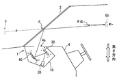
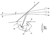
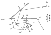
- FIG. 1 is a diagram illustrating an example of a schematic configuration of a head-up display (hereinafter, HUD: Head-Up Display) device 1.
- HUD Head-Up Display
- the HUD device 1 is mounted and used in a vehicle such as a four-wheeled vehicle.
- a height direction and a width direction are set so as to correspond to the posture when attached to the vehicle.
- the width direction for the HUD device 1 is a direction corresponding to the vehicle width direction when attached to the vehicle, and the height direction for the HUD device 1 is the vehicle attached to the vehicle.
- the direction corresponds to the height direction.
- the HUD device 1 projects image light onto a predetermined projection area on the windshield 2 of the vehicle so that the occupant's eyes sitting on the driver's seat and the projection area as shown in FIG.
- the image 3 is displayed as a virtual image on the vehicle front extension line of the line connecting.
- the windshield 2 is a windshield on the front side of the vehicle.
- the windshield 2 should just be implement
- the windshield 2 corresponds to a projection member.
- the projection member may be a member that functions as a half mirror such as a combiner.
- the image light here refers to light that forms a virtual image as the image 3.
- a driver an occupant seated in the driver's seat can visually recognize the HUD image 3 and the foreground of the vehicle in a superimposed manner.
- the image 3 perceived by the driver is hereinafter referred to as a HUD image.
- the type of information indicated by the HUD image 3 may be designed as appropriate.
- FIG. 2 as an example, a mode in which an image indicating a traveling direction at an intersection or the like (an image as a so-called turn-by-turn) is illustrated.
- the HUD image 3 is a display of the system operation state in the advanced driving support function and the automatic driving function, the traveling speed as the vehicle information when the vehicle travels, the engine speed, the engine cooling water temperature, the battery voltage, etc. It is good also as an image which shows any one or more.
- it can also be set as the map image in the vehicle navigation system.
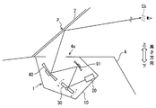
- the HUD device 1 is accommodated in an instrument panel 4 that extends from the lower end of the windshield 2 to the rear of the vehicle interior and further downward. Note that an opening 4 a through which image light emitted from the HUD device 1 passes is provided on the upper surface of the instrument panel 4.
- the opening 4a is provided with a light-transmitting dustproof cover.
- the HUD device 1 is connected to an image signal source 5 disposed outside the HUD device 1 through an in-vehicle network built in the vehicle or a dedicated line for video signals.
- the image signal source 5 is an apparatus that outputs an image signal that is a source of a HUD image (for example, a route guidance image).
- the image signal here is still image data or a video signal.
- the image signal source 5 is, for example, a navigation device or an electronic control device (ECU: Electronic Control Unit) that provides an automatic driving function.
- ECU Electronic Control Unit
- the HUD device 1 is also connected to the viewpoint adjustment switch 6 arranged outside the HUD device 1 (for example, an instrument panel or a steering) through an in-vehicle network or electrically.
- the viewpoint adjustment switch 6 is a switch for the driver to adjust the position of the eye box Eb to a position corresponding to the height of his / her viewpoint.
- the eye box Eb is a viewpoint area where the HUD image 3 can be visually recognized, and is determined by the optical characteristics of the HUD device 1.
- the viewpoint adjustment switch 6 outputs a signal (hereinafter referred to as an operation signal) indicating the operation content by the driver's seat occupant to the control unit 50.
- the driver's seat occupant can adjust the display position of the HUD image 3 to a position corresponding to his / her viewpoint by operating the viewpoint adjustment switch 6.
- the viewpoint adjustment switch 6 can employ, for example, a configuration including two switches, an up switch and a down switch.
- the HUD device 1 includes a housing 10, a projection unit 20, a screen 30, and a concave mirror 40.
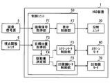
- the HUD device 1 includes a control unit 50, a screen motor 60, and a concave mirror motor 70 as shown in FIG.
- the screen motor 60 and the concave mirror motor 70 are not distinguished, they are abbreviated as motors.
- the housing 10 is configured to accommodate members such as the projection unit 20, the screen 30, the concave mirror 40, the control unit 50, the screen motor 60, and the concave mirror motor 70.
- the housing 10 may be realized using a resin having a predetermined strength, a metal, or the like.
- the housing 10 is fixed to the vehicle, and the position and orientation with respect to the windshield 2 are constant.
- the housing 10 has a certain shape.
- Projection unit 20 is a projector that emits light for forming HUD image 3 (hereinafter also referred to as projection light) based on a control signal input from control unit 50 described later.
- the projection unit 20 is a projector (so-called laser projector) that displays an image by scanning laser light in a two-dimensional direction using a MEMS (Micro Electro Mechanical Systems) scanner.
- MEMS Micro Electro Mechanical Systems
- This type of projection unit 20 includes a laser module that emits laser light and a MEMS scanner that scans the laser light emitted by the laser module in a two-dimensional direction.
- the MEMS scanner is configured so that laser light is scanned in the horizontal direction (so-called horizontal scanning) as one line.
- the number of drawing points per line and the number of lines provided in the vertical direction may be appropriately designed.
- the projection unit 20 draws an image on the screen 30 by sweeping and irradiating laser light onto the screen 30 described later.
- the laser beam swept by the projection unit 20 corresponds to the projection light described above.
- the projection unit 20 is fixed to the housing 10 in a posture in which laser light is emitted in the direction in which the screen 30 exists. That is, the position and orientation of the projection unit 20 with respect to the housing 10 are constant.
- the projection unit 20 is configured such that a focal plane, which is a focal plane (in other words, in focus), is inclined at a predetermined angle (for example, 30 degrees) with respect to the optical axis.
- the projection unit 20 is set with a depth of focus which is a range in focus.
- the depth of focus corresponds to a range on the optical axis where the image of the light beam projected by the projection unit 20 appears sharp even if the focal plane is moved back and forth along the optical axis.
- the depth of focus can be regarded as an area where the image quality of the image finally displayed as the HUD image 3 falls within a predetermined allowable range.
- the focal depth is the distance from the focal length to the front focal depth Lf, which is the distance from the focal point (so-called near point) on the projection unit 20 side, to the critical point (so-called far point) on the opposite side of the projection unit 20 from the focal length.
- the distance can be divided into the rear focal depth Lr, which is the distance.
- the limit point here is a point where the focus is not achieved.
- the depth of focus is a parameter sometimes referred to as a depth of field.
- the depth of focus of the projection unit 20 is determined by the characteristics of an optical system including a lens (not shown) provided in the projection unit 20.
- a mode in which a laser projector is used as the projection unit 20 is disclosed, but the present invention is not limited to this. Other types of projectors can be employed as appropriate.
- the screen 30 is a member (so-called reflection type screen) that diffuses and reflects the laser light emitted from the projection unit 20.
- the screen 30 is disposed so as to reflect image light, which is light obtained by diffusing the projection light emitted from the projection unit 20, in the direction in which the concave mirror 40 exists.
- the screen 30 is formed in a rectangular shape that is long in the horizontal direction.
- the screen 30 is realized by using a micro mirror array (MMA :: Micro Mirror Array).
- the screen 30 may be a reflective diffusion plate such as a holographic diffuser in which aluminum is deposited. Moreover, you may implement
- the surface of the screen 30 where the projection unit 20 exists is referred to as a reflective surface, and the opposite surface is referred to as a back surface.
- the screen 30 is configured such that the tilt angle (in other words, the tilt angle) with respect to the horizontal plane of the vehicle can be changed by the rotational drive of the screen motor 60.
- the vehicle horizontal plane is a horizontal plane for the vehicle and is a plane perpendicular to the height direction of the vehicle.
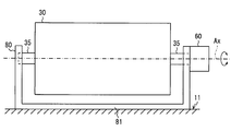
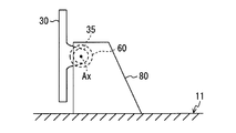
- the screen 30 is rotatably held with respect to the support member 80 using a power transmission member 35 as shown in FIG.
- the power transmission member 35 is a member such as a columnar shape that provides a rotation axis (hereinafter, screen rotation axis) Ax of the screen 30, a columnar shape with a part cut away, or a prismatic shape.
- the power transmission member 35 is fixed to the screen 30 such that the screen rotation axis Ax exists on the reflection surface, for example.
- the power transmission member 35 is held by a support member 80 so as to be rotatable around the screen rotation axis Ax.
- the end of the power transmission member 35 is connected to the output shaft of the screen motor 60 so that the power transmission member 35 is rotated by the rotational drive of the screen motor 60.
- the power transmission member 35 and the output shaft of the screen motor 60 may be connected so that the rotational power provided by the screen motor 60 is transmitted via one or a plurality of gears.
- the screen motor 60 may be configured to rotate (hereinafter referred to as tilt rotation) in the direction in which the tilt angle of the screen 30 changes by the rotational drive of the screen motor 60.
- the support member 80 is a member that rotatably holds the power transmission member 35, and is fixed to the housing 10 by a pedestal portion 81. Locking of the base part 81 and the housing
- the support member 80 and the pedestal portion 81 may be integrally formed. As another aspect, the support member 80 and the pedestal portion 81 may be separate parts.
- the power transmission member 35 is formed integrally with the screen 30 as shown in FIG. According to such a configuration, the number of parts constituting the HUD device 1 can be reduced, and the assembling work can be simplified. As a result, the manufacturing cost of the HUD device 1 can be suppressed.
- the screen 30 defines an angle range (hereinafter referred to as a screen rotation range) in which tilt rotation is possible from a basic posture designed as appropriate.
- a screen rotation range is set from ⁇ sx to + ⁇ sx (including the boundary value).
- the basic posture corresponds to the posture of the screen 30 when the rotation angle ⁇ s by the screen motor 60 is set to 0 degrees.
- the angle (hereinafter referred to as the screen limit rotation angle) ⁇ sx as a boundary value (in other words, the maximum value) that defines the upper limit and the lower limit of the screen rotation range is the upper end (hereinafter referred to as the screen 30).
- Upper end portion) 31 and lower end portion (hereinafter referred to as lower end portion) 32 are set so as not to go out of the depth of focus.
- the basic posture of the screen 30 is indicated by a solid line.
- a broken line indicates the posture of the screen 30 with respect to the projection unit 20 when the screen is tilted forward / backward by the screen limit rotation angle ⁇ sx from the basic posture.
- the upper end portion 31 corresponds to the portion of the screen 30 that is farthest from the screen rotation axis Ax in the portion above the screen rotation axis Ax (hereinafter, the upper half of the screen). That is, the upper end portion 31 corresponds to a portion having the largest displacement amount in the upper half portion of the screen when the screen 30 is rotated.
- the lower end portion 32 corresponds to a portion of the screen 30 that is farthest from the screen rotation axis Ax in a portion below the screen rotation axis Ax (hereinafter referred to as the lower half of the screen). That is, the upper end portion 31 corresponds to a portion having the largest displacement amount in the lower half portion of the screen when the screen 30 is rotated.
- the screen 30 can be prevented from coming out of the focal depth. .
- the configuration in which the screen 30 is not rotated more than the screen limit rotation angle ⁇ sx may be physically realized by using a hardware member, or may be realized by software as a part of the control program for the screen motor 60. good. In the present embodiment, it is assumed that both are adopted.
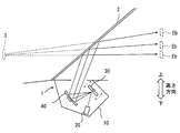
- the incident angle and the projection position of the image light on the concave mirror 40 are changed.
- the projection position (hereinafter referred to as the shield projection position) P of the image light on the windshield 2 is changed.
- the concave mirror 40 is designed to have a size and shape capable of receiving image light output from the screen 30 regardless of the angle within the screen rotation range. Changing the tilt angle of the screen 30 corresponds to changing the posture of the screen 30 with respect to the projection unit 20.
- the concave mirror 40 is configured to reflect the image light emitted from the screen 30 toward the windshield 2 through the opening 4 a provided in the instrument panel 4.
- the concave mirror 40 plays a role of enlarging and displaying the HUD image 3 formed by the image light in addition to the role of guiding the image light to the windshield 2.
- the concave mirror 40 is disposed inside the housing 10 at a position where the image light incident from the screen 30 can be projected onto the windshield 2.
- the concave mirror 40 is configured such that the tilt angle (in other words, the tilt angle) with respect to the vehicle horizontal plane can be changed by the rotational drive of the concave mirror motor 70.
- the rotation axis of the concave mirror 40 (hereinafter referred to as the concave mirror rotation axis) is formed in parallel or substantially parallel to the screen rotation axis Ax.
- the configuration for rotating the concave mirror 40 can be configured similarly to the configuration for rotating the screen 30 by tilting.
- the concave mirror 40 also defines an angle range (hereinafter referred to as a concave mirror rotation range) in which tilt rotation is possible from an appropriately designed basic posture.
- the basic posture of the concave mirror 40 corresponds to the posture of the concave mirror 40 when the rotation angle ⁇ m by the concave mirror motor 70 is set to 0 degree. It is assumed that the concave mirror rotation range is set from ⁇ mx to + ⁇ mx (including the boundary value).
- the concave mirror rotation range is preferably as small as possible.
- the concave mirror rotation range is set to be narrower than the screen rotation range. That is, the angle (hereinafter referred to as concave mirror limit rotation angle) ⁇ mx as a boundary value defining the concave mirror rotation range is set to a value smaller than the screen limit rotation angle ⁇ sx.
- the projection light projected by the projection unit 20 is sequentially reflected by the screen 30 and the concave mirror 40 and led out toward the windshield 2. That is, the screen 30 reflects the projection light projected from the projection unit 20 toward the concave mirror 40, and the concave mirror 40 reflects the image light formed by diffusely reflecting the projection light toward the windshield 2.
- the control unit 50 is configured to control operations of the projection unit 20, the screen motor 60, and the concave mirror motor 70.
- the control unit 50 is electrically connected to each of the projection unit 20, the screen motor 60, and the concave mirror motor 70. Further, the control unit 50 receives an image signal output from the image signal source 5 provided outside the HUD device 1 and an operation signal output from the viewpoint adjustment switch 6.
- the control unit 50 is configured as a computer. That is, the control unit 50 includes a CPU that executes various arithmetic processes, a flash memory that is a nonvolatile memory, a RAM that is a volatile memory, an I / O, a bus line that connects these configurations, and the like.
- the CPU may be realized using, for example, a microprocessor.
- the I / O is an interface for the control unit 50 to input / output data to / from an external device such as the viewpoint adjustment switch 6.
- I / O may be realized using an IC, a digital circuit element, an analog circuit element, or the like.
- the flash memory stores a program for causing a normal computer to function as the control unit 50 (hereinafter, a HUD control program).
- a HUD control program a program for causing a normal computer to function as the control unit 50
- the execution of the HUD control program by the CPU corresponds to the execution of a method corresponding to the HUD control program.
- the control unit 50 provides various functions by the CPU executing the HUD control program. Various functions of the control unit 50 will be described later.
- the screen motor 60 is configured to provide power for rotating the screen 30.
- a stepping motor can be employed as the screen motor 60.
- the screen motor 60 is driven by a control signal output from the control unit 50. That is, the screen motor 60 rotates in the normal rotation direction or the reverse rotation direction by an angle corresponding to the control signal input from the control unit 50.
- An output shaft of the screen motor 60 is connected to the power transmission member 35.
- the screen motor 60 is fixed to the support member 80 so as to be positioned on the side of the screen 30. According to such a configuration, the number of parts arranged on the back side of the screen 30 is reduced, and the length of the casing 10 in the vehicle front-rear direction can be reduced.
- the screen motor 60 may be disposed on the back side of the screen 30. In this case, it is only necessary that the rotational power of the screen motor 60 is transmitted to the power transmission member 35 using a gear or the like. According to the configuration in which the screen motor 60 is disposed on the back side of the screen 30, the length of the housing 10 in the vehicle width direction can be reduced.
- the screen motor 60 provides the control unit 50 with rotation angle data indicating the current rotation angle with respect to the basic posture of the screen 30 (in other words, the amount of displacement of the tilt angle).
- the rotation angle can be detected by using a well-known configuration such as a non-contact rotary sensor or a rotor lipotensometer.
- the concave mirror motor 70 is configured to provide power for rotating the concave mirror 40 around the concave mirror axis.
- a stepping motor can be employed as the concave mirror motor 70.
- the concave mirror motor 70 is driven by a control signal output from the control unit 50. That is, the concave mirror motor 70 rotates in the forward rotation direction or the reverse rotation direction by an angle corresponding to the control signal input from the control unit 50.
- the output shaft of the concave mirror motor 70 is connected to a member that provides a concave mirror rotation axis.
- the concave mirror motor 70 provides rotation angle data indicating the current rotation angle with respect to the basic posture of the concave mirror 40 to the control unit 50. It should be noted that the installation position of the concave mirror motor 70 may be designed as appropriate, and here, as an example, the concave mirror motor 70 is disposed on the side of the concave mirror 40. Of course, the concave mirror motor 70 may be disposed on the back side of the concave mirror 40.
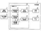
- the control unit 50 provides various functions shown in FIG. 3 by the CPU executing a HUD control program stored in the flash memory. That is, the control unit 50 includes an image signal acquisition unit F1, a display control unit F2, a target position acquisition unit F3, a drive amount determination unit F4, a screen motor control unit F5, and a concave mirror motor control unit F6 as functional blocks.
- control unit 50 may be realized as hardware by one or a plurality of ICs. Further, some or all of the functional blocks provided in the control unit 50 may be realized by a combination of execution of software by the CPU and hardware members.
- the image signal acquisition unit F1 converts the image signal input from the image signal source 5 into a data format that can be recognized by the display control unit F2, and outputs the data format to the display control unit F2.
- the display control unit F2 controls the operation of the projection unit 20, and causes the projection unit 20 to project the projection light that is the basis of the desired HUD image 3. For example, the display control unit F2 causes the projection unit 20 to project the projection light that is the source of the route guidance image.
- the target position acquisition unit F3 specifies the current rotation angle of the screen 30 and the rotation angle of the concave mirror 40 based on the rotation angle data provided from the screen motor 60 and the concave mirror motor 70, respectively. Then, based on at least one of the rotation angle of the screen 30 and the rotation angle of the concave mirror 40, the current position in the vertical direction of the eye box Eb (hereinafter referred to as the viewpoint position) is specified.
- the adjustment of the viewpoint position in the present embodiment is realized by controlling both the shield projection position P and the incident angle.
- angle setting data data indicating the rotation angle of the screen 30 and the rotation angle of the concave mirror 40 for realizing the viewpoint position.
- the position acquisition unit F3 specifies the current viewpoint position using the angle setting data. That is, the viewpoint position corresponding to the current rotation angle of the screen 30 and the rotation angle of the concave mirror 40 is adopted as the current viewpoint position.
- the angle setting data here corresponds to data indicating the respective rotation angles of the screen 30 and the concave mirror 40 in accordance with the position of the eye box Eb.
- the viewpoint position can be adjusted up and down as shown in FIG. At that time, the center position of the HUD image seems to be fixed at one point on a certain space.
- the position of the HUD image 3 moves to the side opposite to the eye box Eb.
- the display position of the HUD image 3 is formed on a straight line passing through the point A ′ on the space determined by the optical characteristics of the concave mirror 40 and the viewpoint position.
- the point A ′ corresponds to the position of the concave mirror 40 where the virtual image of the point A where the center of the image light is incident is formed by the windshield 2.
- the rotation angle corresponding to each viewpoint position is set so that the concave mirror 40 also rotates in conjunction with the rotation of the screen 30.
- the rotation angle of the concave mirror 40 required to move the viewpoint position by a certain amount is set to be smaller than the rotation angle of the screen 30.
- the screen 30 that is a relatively small member is mainly rotated so that a desired viewpoint position can be provided while suppressing the rotation angle of the concave mirror 40 that is a relatively large member.
- the rotation angles of the screen 30 and the concave mirror 40 are set to a necessary and sufficient angle for realizing a desired viewpoint position.
- the target position acquisition unit F3 acquires the content of the operation performed by the driver on the viewpoint adjustment switch 6 based on the operation signal input from the viewpoint adjustment switch 6. That is, it is acquired whether or not the driver has performed an operation for instructing to move the viewpoint position upward / downward. That is, the operation signal acquired by the target position acquisition unit F3 functions as information for determining the moving direction and moving amount of the eye box Eb.
- the target position acquisition unit F3 specifies a target viewpoint position (hereinafter, target viewpoint position) based on the current viewpoint position and the operation content performed by the driver on the viewpoint adjustment switch 6.
- the moving direction of the viewpoint position may be determined according to the type of button operated by the driver. Further, the movement amount of the viewpoint position may be determined by the length of time or the number of times the switch is pressed. For example, when the up switch is pressed once, a position obtained by moving the viewpoint position by a predetermined amount in the upward direction is set as the target viewpoint position.
- the viewpoint position is adjusted by adjusting the tilt angles of the screen 30 and the concave mirror 40. Therefore, the operation information functions as information for determining the adjustment amounts of the respective tilt angles of the screen 30 and the concave mirror 40.
- the target position acquisition unit F3 corresponds to a target viewpoint position acquisition unit.
- the driving amount determination unit F4 determines the driving amounts of the screen motor 60 and the concave mirror motor 70 based on the current viewpoint position acquired by the target position acquisition unit F3 and the target viewpoint position. Specifically, the drive amount determination unit F4 specifies the rotation angle of the screen 30 and the rotation angle of the concave mirror 40 corresponding to the target viewpoint position with reference to the angle setting data.
- an adjustment amount of the tilt angle of the screen 30 (hereinafter, screen angle adjustment amount) is determined by subtracting the current rotation angle of the screen 30 from the rotation angle of the screen 30 corresponding to the target viewpoint position, and the screen motor 60 The driving amount of is determined. Further, the adjustment amount of the tilt angle of the concave mirror 40 (hereinafter referred to as the concave mirror angle adjustment amount) is determined by subtracting the current rotation angle of the concave mirror 40 from the rotation angle of the concave mirror 40 corresponding to the target viewpoint position, and the concave mirror motor 70. The driving amount of is determined.
- the drive amount determination unit F4 notifies the rotation direction and drive amount of each motor determined above to the screen motor control unit F5 and the concave mirror motor control unit F6. In other words, the control contents are instructed to the screen motor control unit F5 and the concave mirror motor control unit F6. It should be noted that the driving amount of each motor determined as described above takes a positive / negative value and expresses the direction in which the motor is rotated by positive / negative.
- the drive amount determination unit F4 does not drive each motor and keeps the viewpoint position at the current position even if the operation information indicating that the viewpoint is moved further upward is acquired. The same applies when the viewpoint position reaches the lower limit position.
- the position of the eye box Eb in a state where the rotation angle of the screen 30 and the concave mirror 40 is set to 0 ° corresponds to the basic position (in other words, the initial position) of the eye box Eb.
- the screen motor control unit F5 generates a control signal for the screen motor 60 corresponding to the control content instructed by the drive amount determination unit F4 and outputs the control signal to the screen motor 60. That is, a control signal for rotating in the direction instructed by the drive amount determination unit F4 by the instructed amount is generated and output.
- the screen motor 60 is rotationally driven based on the control signal input from the screen motor control unit F5, and changes the tilt angle of the screen 30. As a result, the incident position and incident angle of the image light at the concave mirror 40 change.
- the concave mirror motor control unit F6 generates a control signal for the concave mirror motor 70 corresponding to the control content instructed from the drive amount determination unit F4, and outputs the control signal to the concave mirror motor 70. That is, a control signal for rotating in the direction instructed by the drive amount determination unit F4 by the instructed drive amount is generated and output.
- the concave mirror motor 70 is rotationally driven based on a control signal input from the concave mirror motor control unit F6, and changes the tilt angle of the concave mirror 40. As a result, the incident position and incident angle of the image light at the concave mirror 40 change.
- the projection position of the image light on the windshield 2 (that is, the shield projection position) P and the incident angle are adjusted by interlockingly adjusting the angles of the screen 30 and the concave mirror 40 based on the driver operation. Adjust.
- the position of the eye box Eb can be adapted to the viewpoint position of the driver, and the depression angle of the HUD image 3 can also be adapted.
- the concave mirror 40 required for moving the height of the eye box Eb by a fixed amount is more than the configuration in which the viewpoint position is adjusted by rotating only the concave mirror 40 (hereinafter, assumed configuration).
- the rotation angle can be suppressed. That is, the movable range of the concave mirror 40 can be reduced.
- the volume of empty space (so-called clearance) formed for rotating the concave mirror 40 around the concave mirror 40 can be reduced. Therefore, even when the concave mirror 40 is enlarged to increase the screen size of the HUD device 1, an increase in the volume of the housing 10 due to the size increase of the concave mirror 40 can be suppressed.
- the movable range of the concave mirror 40 can be reduced, it is possible to increase the rotational torque by reducing the rotational speed by adjusting the gear ratio, and it is possible to move even a motor with a smaller output. Therefore, the size of the motor (that is, the concave mirror motor) 70 for rotating the concave mirror 40 can be reduced, and the increase in the volume of the housing 10 accompanying the increase in the size of the concave mirror 40 can be further suppressed.
- the virtual image depression angle ⁇ dp is a display position of the HUD image 3 that can be seen from the driver, and corresponds to an angle formed by a line connecting the shield projection position P and the eye box Eb with respect to the vehicle horizontal plane.
- the screen position and the screen rotation range are set so that the upper end 31 and the lower end 32 do not exceed the depth of focus of the projection unit 20 when the screen 30 is rotated. According to such a configuration, it is possible to reduce the possibility that the HUD image 3 is blurred and displayed due to the adjustment of the position of the eye box Eb.
- the screen 30 and the concave mirror 40 are rotated, but the present invention is not limited to this.
- the concave mirror 40 may be fixed to the housing 10 so that it cannot be rotated from a predetermined basic posture. Such a configuration will be described below as a first modification.
- the concave mirror 40 is fixed to the housing 10 in a predetermined posture. Therefore, the HUD device 1 of the first modification does not include the concave mirror motor 70. Accordingly, as shown in FIG. 9, the control unit 50 does not include the concave mirror motor control unit F6.
- the height adjustment of the eye box Eb (that is, the adjustment of the viewpoint position) is realized by adjusting the angle of the screen 30. Therefore, the rotation angle of the screen 30 necessary for moving the height of the eye box Eb by a certain amount is set to be larger than the configuration of the embodiment.
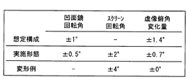
- the concave mirror 40 is fixed, the change amount of the virtual image depression angle can be suppressed to a relatively small value.
- the change amount of the virtual image depression angle that occurs when the height of the eye box Eb is increased by 20 mm from the basic position can be made smaller than that of the embodiment as shown in FIG.
- the configuration of the first modification by devising the positional relationship of the optical system members, it is also possible to suppress the virtual image depression angle change amount to a value that can be regarded as 0 degrees. .
- FIG. 10 shows the screen 30 required for moving the height of the eye box Eb upward / downward by 20 mm from the basic position in each of the assumed configuration, the configuration of the embodiment, and the configuration of the first modification.
- the example of the result of having tested the rotation angle, the rotation angle of the concave mirror 40, and the resulting virtual image depression angle change amount is shown.
- the basic position of the eye box Eb in the first modification is the position of the eye box Eb in a state where the rotation angle of the screen 30 is set to 0 °.
- the volume of the housing 10 can be reduced. Moreover, since it is not necessary to arrange the concave mirror motor 70, the volume of the housing 10 can be further reduced.
- the concave mirror 40 can be fixed to the housing 10 at a plurality of points, the display is less likely to shake even under vehicle vibration, and durability against vehicle vibration can be improved. This is because if the concave mirror 40 is fixed to the housing 10 at a plurality of points, the resonance frequency of the concave mirror 40 becomes higher than a frequency band in which vehicle vibrations are mainly distributed.
- the concave mirror 40 can be fixed to the housing 10 at a plurality of points, a configuration for supporting the concave mirror 40 on the housing 10 (hereinafter referred to as a concave mirror support member) compared to the case where the concave mirror 40 is supported by a power transmission member.
- the required rigidity is reduced.
- the thickness and volume of the concave mirror support member can be reduced, and the volume of the housing 10 can be further reduced.
- the concave mirror motor 70 is unnecessary, the cost of components can be reduced by the amount of the concave mirror motor 70. Further, since the mechanism of the HUD device 1 is simplified as compared with the embodiment due to the absence of the concave mirror motor 70, the assembling work is also relatively simplified. Therefore, the manufacturing cost of the HUD device 1 can be reduced.
- auxiliary mirror 90 another mirror (hereinafter referred to as an auxiliary mirror) 90 may be disposed between the screen 30 and the concave mirror 40.
- the auxiliary mirror 90 is configured to reflect the image light diffusely reflected by the screen 30 toward the concave mirror 40.
- the auxiliary mirror 90 may be a concave mirror or a convex mirror.
- the auxiliary mirror 90 may be a plane mirror.
- the auxiliary mirror 90 is disposed between the screen 30 and the concave mirror 40, when the HUD image 3 is displayed relatively far, distortion of the shape generated in the HUD image 3 is suppressed. Can do.
- the HUD image 3 can be displayed more clearly than the configuration in which the HUD image 3 is enlarged and displayed only by the concave mirror 40.
- optical system components such as a lens 91 and a mirror 92 may be disposed between the projection unit 20 and the screen 30.
- the optical system component is a component having a function of reflecting and refracting light.
- the optical system in the housing 10 may be configured so that the projection light projected from the projection unit 20 forms an image on the screen 30.
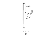
- the power transmission member 35 may be provided on the screen 30 so that the screen rotation axis Ax is formed on the back side of the screen 30.
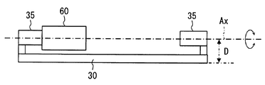
- D shown in FIG.13 and FIG.14 represents the distance from the reflective surface of the screen 30 to the screen rotation axis Ax.
- the distance D may be designed as appropriate.
- the distance D may be set to a length that allows the screen 30 to rotate without causing interference between the screen motor 60 and the screen 30 even if the output shaft of the screen motor 60 is directly connected to the power transmission member 35.
- the screen motor 60 can be disposed on the back side of the screen 30 as shown in FIG. Even when the distance D is relatively small or when the screen rotation axis Ax is formed on the reflection surface side of the screen 30, the screen motor 60 can be obtained by using a power transmission member such as a gear or a link. Can be arranged on the back side of the screen 30.
- the rotation axis Ax can be rotated from a motor output shaft at a point far from the rotation axis Ax or at a twisted position while suppressing an increase in the number of parts compared to the case of using a gear. Therefore, the degree of freedom of arrangement of the motor can be increased, and the mountability on the vehicle can be improved.
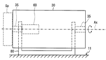
- FIG. 15 and 16 are diagrams showing an example of a configuration in which the screen motor 60, the support member 80, and the like are arranged on the back side of the screen 30.
- FIG. 15 conceptually shows the position of each member such as the screen motor 60 when the screen 30 is viewed from the front
- FIG. 16 conceptually shows the configuration when the screen 30 is viewed from the side. ing.
- the screen motor 60 is provided on the side of the screen 30 illustrated in FIG.
- the lateral length of the overall configuration related to the screen 30 can be suppressed. As a result, the degree of freedom of mounting on the vehicle can be increased.
- APC Auto Power Control
- APC is a function that emits test laser light (hereinafter referred to as APC light) outside the image forming area and automatically adjusts the output of the laser light source based on the received light intensity of the test laser light. is there.
- the APC light absorption mechanism is a structure that receives APC light and absorbs APC light so as not to be irregularly reflected.
- the APC light absorption mechanism needs to be arranged in the scanning direction of the laser light. That is, the APC light absorption mechanism needs to be arranged on the side of the screen 30.
- the APC light absorbing mechanism is arranged on the side of the screen 30 as shown in FIG. It is easy to secure the space Sp. That is, the configuration in which the screen motor 60 and the like are arranged on the back side of the screen 30 is preferable in a configuration in which a radar projector is used as the projection unit 20.
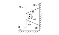
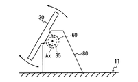
- the support member 80 may be fixed to the floor portion 11 that is a portion of the inner side surface of the housing 10 that is located below the reflecting surface, or as shown in FIG. You may fix to the back part 12 which is a part located in the side. As shown in FIG. 17, according to the aspect in which the support member 80 is fixed to the back surface portion 12, the height of the casing 10 around the screen 30 can be suppressed, and the degree of freedom of mounting on the vehicle is increased. Can do. Moreover, as shown in FIG. 18, you may be comprised so that the state in which the screen 30 inclined with respect to the floor surface part 11 may become a basic attitude
- the target position acquisition unit F3 disclosed a mode of determining the position of the eye box Eb that matches the viewpoint position of the driver, in other words, the target projection position Pt, based on the output of the viewpoint adjustment switch 6.
- the position of the driver's eyes may be detected based on a captured image of a camera installed so as to capture the face of the driver, and the target projection position Pt may be determined based on the detection result.
- the configuration in which the laser projector is employed as the projection unit 20 is disclosed, but the configuration is not limited thereto.
- the projection unit 20 may be another type of projector such as a liquid crystal projector.
- the laser projector has a greater depth of focus than other types of projectors (for example, liquid crystal projectors). Therefore, the rotation range of the screen 30 can be set relatively large. Therefore, the present disclosure is suitable for the HUD device 1 using a laser projector.
- this indication is applicable to the HUD apparatus 1 of the type which uses a reflection type screen.
Landscapes
- Physics & Mathematics (AREA)
- Engineering & Computer Science (AREA)
- General Physics & Mathematics (AREA)
- Optics & Photonics (AREA)
- Chemical & Material Sciences (AREA)
- Combustion & Propulsion (AREA)
- Transportation (AREA)
- Mechanical Engineering (AREA)
- Instrument Panels (AREA)
- Transforming Electric Information Into Light Information (AREA)
Abstract
Selon la présente invention, un dispositif d'affichage tête haute permettant de projeter de la lumière indiquant une image sur un élément de projection et d'afficher ainsi l'image sous la forme d'une image virtuelle dans une position prédéterminée devant un siège du conducteur est pourvu d'un boîtier (10), d'une unité de projection (20) servant à projeter une lumière de projection permettant d'indiquer l'image, d'un écran de type réflexion (30) servant à réfléchir de manière diffuse la lumière de projection, d'un miroir concave (40) servant à agrandir et à réfléchir la lumière d'image qui est la lumière de la lumière de projection réfléchie de manière diffuse par l'écran de type à réflexion vers l'élément de projection, d'un moteur d'écran (60) servant à faire tourner l'écran de type réflexion dans une direction dans laquelle l'angle d'inclinaison de l'écran de type réflexion change, et d'une unité de commande de moteur d'écran (F5) servant à commander le fonctionnement du moteur d'écran.
Applications Claiming Priority (2)
| Application Number | Priority Date | Filing Date | Title |
|---|---|---|---|
| JP2017110300A JP6693474B2 (ja) | 2017-06-02 | 2017-06-02 | ヘッドアップディスプレイ装置 |
| JP2017-110300 | 2017-06-02 |
Publications (1)
| Publication Number | Publication Date |
|---|---|
| WO2018221070A1 true WO2018221070A1 (fr) | 2018-12-06 |
Family
ID=64455764
Family Applications (1)
| Application Number | Title | Priority Date | Filing Date |
|---|---|---|---|
| PCT/JP2018/016384 WO2018221070A1 (fr) | 2017-06-02 | 2018-04-23 | Dispositif d'affichage tête haute |
Country Status (2)
| Country | Link |
|---|---|
| JP (1) | JP6693474B2 (fr) |
| WO (1) | WO2018221070A1 (fr) |
Cited By (2)
| Publication number | Priority date | Publication date | Assignee | Title |
|---|---|---|---|---|
| EP3683615A1 (fr) * | 2019-01-18 | 2020-07-22 | Continental Automotive GmbH | Dispositif d'affichage tête haute pour véhicule et véhicule |
| CN111645704A (zh) * | 2020-06-18 | 2020-09-11 | 摩登汽车有限公司 | 车载抬头显示器的控制系统及汽车 |
Families Citing this family (4)
| Publication number | Priority date | Publication date | Assignee | Title |
|---|---|---|---|---|
| JP7196769B2 (ja) * | 2019-05-29 | 2022-12-27 | 株式会社デンソー | レーザ走査式映像装置 |
| JP7367525B2 (ja) * | 2019-12-26 | 2023-10-24 | 株式会社リコー | 表示装置、表示システムおよび移動体 |
| WO2021156678A1 (fr) * | 2020-02-05 | 2021-08-12 | Unity Technologies ApS | Affichage tête haute industriel |
| DE112022001951T5 (de) | 2021-03-31 | 2024-01-25 | Koito Manufacturing Co., Ltd. | Bilderzeugungsvorrichtung, Bildbestrahlungsvorrichtung, die mit dieser Bilderzeugungsvorrichtung ausgestattet ist, und Bildbestrahlungsvorrichtung |
Citations (6)
| Publication number | Priority date | Publication date | Assignee | Title |
|---|---|---|---|---|
| JPH10333080A (ja) * | 1997-05-30 | 1998-12-18 | Shimadzu Corp | ヘッドアップディスプレイ |
| JP2009163122A (ja) * | 2008-01-09 | 2009-07-23 | Denso Corp | 画像形成装置 |
| JP2011203680A (ja) * | 2010-03-26 | 2011-10-13 | Denso Corp | ヘッドアップディスプレイ装置 |
| JP2014026244A (ja) * | 2012-07-30 | 2014-02-06 | Jvc Kenwood Corp | 表示装置 |
| WO2016014712A1 (fr) * | 2014-07-22 | 2016-01-28 | Navdy, Inc. | Système d'affichage tête haute compact |
| US20160266390A1 (en) * | 2015-03-11 | 2016-09-15 | Hyundai Mobis Co., Ltd. | Head-up display and control method thereof |
Family Cites Families (1)
| Publication number | Priority date | Publication date | Assignee | Title |
|---|---|---|---|---|
| WO2017130763A1 (fr) * | 2016-01-27 | 2017-08-03 | 日本精機株式会社 | Dispositif d'affichage tête haute |
-
2017
- 2017-06-02 JP JP2017110300A patent/JP6693474B2/ja active Active
-
2018
- 2018-04-23 WO PCT/JP2018/016384 patent/WO2018221070A1/fr active Application Filing
Patent Citations (6)
| Publication number | Priority date | Publication date | Assignee | Title |
|---|---|---|---|---|
| JPH10333080A (ja) * | 1997-05-30 | 1998-12-18 | Shimadzu Corp | ヘッドアップディスプレイ |
| JP2009163122A (ja) * | 2008-01-09 | 2009-07-23 | Denso Corp | 画像形成装置 |
| JP2011203680A (ja) * | 2010-03-26 | 2011-10-13 | Denso Corp | ヘッドアップディスプレイ装置 |
| JP2014026244A (ja) * | 2012-07-30 | 2014-02-06 | Jvc Kenwood Corp | 表示装置 |
| WO2016014712A1 (fr) * | 2014-07-22 | 2016-01-28 | Navdy, Inc. | Système d'affichage tête haute compact |
| US20160266390A1 (en) * | 2015-03-11 | 2016-09-15 | Hyundai Mobis Co., Ltd. | Head-up display and control method thereof |
Cited By (2)
| Publication number | Priority date | Publication date | Assignee | Title |
|---|---|---|---|---|
| EP3683615A1 (fr) * | 2019-01-18 | 2020-07-22 | Continental Automotive GmbH | Dispositif d'affichage tête haute pour véhicule et véhicule |
| CN111645704A (zh) * | 2020-06-18 | 2020-09-11 | 摩登汽车有限公司 | 车载抬头显示器的控制系统及汽车 |
Also Published As
| Publication number | Publication date |
|---|---|
| JP6693474B2 (ja) | 2020-05-13 |
| JP2018205509A (ja) | 2018-12-27 |
Similar Documents
| Publication | Publication Date | Title |
|---|---|---|
| WO2018221070A1 (fr) | Dispositif d'affichage tête haute | |
| JP6731644B2 (ja) | 表示位置補正装置、表示位置補正装置を備える表示装置、及び表示装置を備える移動体 | |
| US10302940B2 (en) | Head-up display | |
| JP5240222B2 (ja) | ヘッドアップディスプレイ装置 | |
| KR101408523B1 (ko) | 헤드업 디스플레이 장치 | |
| JP5299947B2 (ja) | 投射用スクリーン及び表示システム | |
| JP2004168230A (ja) | 車両用表示装置 | |
| JP6874659B2 (ja) | 車両用表示装置および車両用表示システム | |
| JP2003039981A (ja) | 車載用ヘッドアップディスプレイ装置 | |
| US11226490B2 (en) | Virtual image display device | |
| EP3543766A1 (fr) | Dispositif d'affichage d'image virtuelle, unité de formation d'image intermédiaire et unité de génération de lumière d'affichage d'image | |
| WO2018123528A1 (fr) | Dispositif d'affichage et corps mobile portant le dispositif d'affichage | |
| JP2019066527A (ja) | 虚像表示装置 | |
| KR20170008430A (ko) | 헤드 업 디스플레이 장치 | |
| JP2010149733A (ja) | ヘッドアップディスプレイ装置 | |
| JP2009222882A (ja) | ヘッドアップディスプレイ装置 | |
| JP2018177015A (ja) | 車両用表示装置 | |
| US20190012983A1 (en) | Projection display device, projection control method, and projection control program | |
| WO2018168708A1 (fr) | Dispositif d'affichage | |
| JP7059987B2 (ja) | ウィンドシールド表示装置 | |
| JP7419756B2 (ja) | 虚像表示装置 | |
| JP2018105939A (ja) | ヘッドアップディスプレイ装置 | |
| JP6593494B1 (ja) | 虚像表示装置 | |
| JP7005107B2 (ja) | 車両用表示装置 | |
| JP2022130094A (ja) | ミラー及びヘッドアップディスプレイ装置 |
Legal Events
| Date | Code | Title | Description |
|---|---|---|---|
| 121 | Ep: the epo has been informed by wipo that ep was designated in this application |
Ref document number: 18810612 Country of ref document: EP Kind code of ref document: A1 |
|
| NENP | Non-entry into the national phase |
Ref country code: DE |
|
| 122 | Ep: pct application non-entry in european phase |
Ref document number: 18810612 Country of ref document: EP Kind code of ref document: A1 |