WO2018221043A1 - 診断装置 - Google Patents
診断装置 Download PDFInfo
- Publication number
- WO2018221043A1 WO2018221043A1 PCT/JP2018/015783 JP2018015783W WO2018221043A1 WO 2018221043 A1 WO2018221043 A1 WO 2018221043A1 JP 2018015783 W JP2018015783 W JP 2018015783W WO 2018221043 A1 WO2018221043 A1 WO 2018221043A1
- Authority
- WO
- WIPO (PCT)
- Prior art keywords
- diagnostic
- expansion device
- pulse generator
- cutoff
- signal
- Prior art date
Links
Images


Classifications
-
- G—PHYSICS
- G01—MEASURING; TESTING
- G01R—MEASURING ELECTRIC VARIABLES; MEASURING MAGNETIC VARIABLES
- G01R31/00—Arrangements for testing electric properties; Arrangements for locating electric faults; Arrangements for electrical testing characterised by what is being tested not provided for elsewhere
- G01R31/50—Testing of electric apparatus, lines, cables or components for short-circuits, continuity, leakage current or incorrect line connections
- G01R31/56—Testing of electric apparatus
-
- G—PHYSICS
- G01—MEASURING; TESTING
- G01R—MEASURING ELECTRIC VARIABLES; MEASURING MAGNETIC VARIABLES
- G01R31/00—Arrangements for testing electric properties; Arrangements for locating electric faults; Arrangements for electrical testing characterised by what is being tested not provided for elsewhere
- G01R31/327—Testing of circuit interrupters, switches or circuit-breakers
- G01R31/3271—Testing of circuit interrupters, switches or circuit-breakers of high voltage or medium voltage devices
- G01R31/3275—Fault detection or status indication
-
- G—PHYSICS
- G05—CONTROLLING; REGULATING
- G05B—CONTROL OR REGULATING SYSTEMS IN GENERAL; FUNCTIONAL ELEMENTS OF SUCH SYSTEMS; MONITORING OR TESTING ARRANGEMENTS FOR SUCH SYSTEMS OR ELEMENTS
- G05B9/00—Safety arrangements
- G05B9/02—Safety arrangements electric
-
- H—ELECTRICITY
- H02—GENERATION; CONVERSION OR DISTRIBUTION OF ELECTRIC POWER
- H02P—CONTROL OR REGULATION OF ELECTRIC MOTORS, ELECTRIC GENERATORS OR DYNAMO-ELECTRIC CONVERTERS; CONTROLLING TRANSFORMERS, REACTORS OR CHOKE COILS
- H02P29/00—Arrangements for regulating or controlling electric motors, appropriate for both AC and DC motors
- H02P29/02—Providing protection against overload without automatic interruption of supply
- H02P29/024—Detecting a fault condition, e.g. short circuit, locked rotor, open circuit or loss of load
- H02P29/0241—Detecting a fault condition, e.g. short circuit, locked rotor, open circuit or loss of load the fault being an overvoltage
-
- G—PHYSICS
- G01—MEASURING; TESTING
- G01R—MEASURING ELECTRIC VARIABLES; MEASURING MAGNETIC VARIABLES
- G01R31/00—Arrangements for testing electric properties; Arrangements for locating electric faults; Arrangements for electrical testing characterised by what is being tested not provided for elsewhere
- G01R31/50—Testing of electric apparatus, lines, cables or components for short-circuits, continuity, leakage current or incorrect line connections
- G01R31/54—Testing for continuity
-
- H—ELECTRICITY
- H02—GENERATION; CONVERSION OR DISTRIBUTION OF ELECTRIC POWER
- H02H—EMERGENCY PROTECTIVE CIRCUIT ARRANGEMENTS
- H02H3/00—Emergency protective circuit arrangements for automatic disconnection directly responsive to an undesired change from normal electric working condition with or without subsequent reconnection ; integrated protection
- H02H3/02—Details
- H02H3/04—Details with warning or supervision in addition to disconnection, e.g. for indicating that protective apparatus has functioned
- H02H3/044—Checking correct functioning of protective arrangements, e.g. by simulating a fault
-
- H—ELECTRICITY
- H02—GENERATION; CONVERSION OR DISTRIBUTION OF ELECTRIC POWER
- H02H—EMERGENCY PROTECTIVE CIRCUIT ARRANGEMENTS
- H02H3/00—Emergency protective circuit arrangements for automatic disconnection directly responsive to an undesired change from normal electric working condition with or without subsequent reconnection ; integrated protection
- H02H3/02—Details
- H02H3/05—Details with means for increasing reliability, e.g. redundancy arrangements
Definitions
- the present invention relates to a diagnostic apparatus for diagnosing the presence or absence of a circuit abnormality.
- An expansion device is connected to the conventional control device, and the motor is operated by the expansion device.
- the encoder information is taken in and the rotational speed and movement area of the motor shaft are monitored.
- the configuration of the conventional emergency stop circuit cannot detect that the emergency stop circuit in a state where the expansion device is connected to the control device has failed.
- the diagnostic device includes a control device and an expansion device that can be connected to the control device, and the control device is configured to supply a power to the load unit and cut off the power, and to the load unit.
- the expansion device is connected to the first diagnostic pulse generator for generating a diagnostic signal indicating that the supply of electric power is cut off, the first cutoff diagnostic device for detecting the supply voltage to the load unit, and the control device
- An expansion device detector for detecting whether or not the expansion device includes a second diagnostic pulse generator for generating the diagnostic signal, and a second cutoff diagnostic device for detecting a supply voltage to the load unit. And when the expansion device detector detects that the expansion device is not connected to the control device, the first diagnostic pulse generator outputs the diagnostic signal to the blocking unit.
- the blocking section is the first In response to the diagnostic signal output from the diagnostic pulse generator, the supply of power to the load unit is cut off, and the first cutoff diagnostic device is configured to detect the supply voltage to the load unit based on the detected supply voltage.
- the second diagnostic pulse generator is configured to diagnose the presence or absence of a failure related to the shut-off unit and detect that the extension device is connected to the control device by the extension device detector.
- the diagnostic signal is output to a unit, and the cutoff unit shuts off the supply of power to the load unit in response to the diagnostic signal output from the second diagnostic pulse generator,
- the interruption diagnostic device is characterized by diagnosing the presence / absence of a failure related to the interruption unit based on the detected supply voltage to the load unit.
- a diagnostic device includes a motor control device and an expansion device connectable to the motor control device, and the motor control device is an inverter that controls a voltage applied to the motor by PWM (Pulse Width Modulation) control.
- the expansion device includes a second diagnostic pulse generator that generates the diagnostic signal and a second cutoff diagnostic device that detects a supply voltage to the drive circuit, and the expansion device detector When it is detected that the expansion device is not connected to the motor control device, the first diagnostic pulse generator outputs the diagnostic signal to the cutoff circuit, and the cutoff circuit is In response to the diagnostic signal output from the first diagnostic pulse generator, the supply
- the second diagnostic pulse generator when the expansion device detector detects that the expansion device is connected to the motor control device. Outputs the diagnostic signal to the cutoff circuit, and the cutoff circuit cuts off the supply of power to the drive circuit in response to the diagnostic signal output from the second diagnostic pulse generator.
- the second shut-off Sectional instrument based on the supply voltage to the drive circuit for detecting, characterized in that detects the presence of a fault according to the blocking circuit.
- the diagnostic device having the above configuration, it is possible to detect that the interruption circuit that is an emergency stop circuit in a state where the expansion device is connected to the control device has failed.
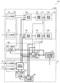
- FIG. 1 is a block configuration diagram of the diagnostic apparatus according to the first embodiment.
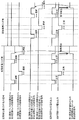
- FIG. 2 is an operation waveform diagram of the diagnostic apparatus according to the first embodiment.
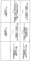
- FIG. 3 is a schematic diagram of a combination pattern of the expansion device and the result of the expansion device detector in the first embodiment.
- FIG. 4 is a block configuration diagram of the diagnostic apparatus according to the second embodiment.
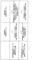
- FIG. 5 is a schematic diagram of a combination pattern of the expansion device and the result of the expansion device detector in the second embodiment.
- FIG. 6 is a block configuration diagram of the diagnostic apparatus according to the third embodiment.
- FIG. 7 is an operation waveform diagram of the diagnostic apparatus according to the third embodiment.
- FIG. 8 is a schematic diagram of a combination pattern as a result of the expansion device and the expansion device detector in the third embodiment.
- FIG. 9 is a block configuration diagram of the diagnostic apparatus according to the fourth embodiment.
- FIG. 10 is a schematic diagram of a combination pattern as a result of the expansion device and the expansion device detector in the fourth embodiment.
- FIG. 11 is a block diagram of a conventional cutoff circuit.
- a diagnostic device includes a control device and an expansion device that can be connected to the control device, and the control device includes a cutoff unit that switches between supply and cutoff of power to a load unit, and A first diagnostic pulse generator for generating a diagnostic signal indicating that the supply of power to the load unit is cut off; a first cutoff diagnostic device for detecting a supply voltage to the load unit; And an expansion device detector for detecting whether or not is connected, the expansion device comprising: a second diagnostic pulse generator for generating the diagnostic signal; and a second cutoff for detecting a supply voltage to the load unit And when the expansion device detector detects that the expansion device is not connected to the control device, the first diagnostic pulse generator is configured to A diagnostic signal is output, and the blocking unit In response to the diagnostic signal output from the first diagnostic pulse generator, the supply of power to the load unit is cut off, and the first cutoff diagnostic device is based on the detected supply voltage to the load unit.
- the second diagnostic pulse generator is configured to diagnose the presence or absence of a failure related to the shut-off unit and detect that the expansion device is connected to the control device by the expansion device detector. , Outputting the diagnostic signal to the cutoff unit, the cutoff unit shuts off the supply of power to the load unit in response to the diagnostic signal output from the second diagnostic pulse generator, The second shutoff diagnostic device diagnoses the presence / absence of a failure related to the shutoff unit based on a detected supply voltage to the load unit.
- the diagnostic device having the above configuration, it is possible to detect that the interruption circuit that is an emergency stop circuit in a state where the expansion device is connected has failed.
- first diagnostic pulse generator and the second diagnostic pulse generator may output the diagnostic signal with different periods or different phases to the blocking unit.
- the expansion device detector detects that the expansion device is not connected even though the expansion device is connected, and the expansion device is not connected, even though the expansion device is not connected.
- an abnormal state that is detected when the expansion device is connected can be detected relatively easily.
- the first cutoff diagnostic device is further output from the second diagnostic pulse generator.
- the presence or absence of a failure related to the expansion device may be diagnosed based on whether or not the diagnostic signal is detected.
- a diagnostic device includes a motor control device and an expansion device connectable to the motor control device, and the motor control device applies a voltage to be applied to the motor by PWM (PulseulWidth Modulation) control.
- a first diagnostic pulse generator for generating, a first cutoff diagnostic device for detecting a supply voltage to the drive circuit, and an expansion device detector for detecting whether or not the expansion device is connected to the motor control device;
- the expansion device includes a second diagnostic pulse generator that generates the diagnostic signal and a second cutoff diagnostic device that detects a supply voltage to the drive circuit, and the expansion device detection When it is detected that the expansion device is not connected to the motor control device, the first diagnostic pulse generator outputs the diagnostic signal to the cutoff circuit, and the cutoff circuit In response to the PWM
- the presence or absence of a failure relating to the shut-off circuit is diagnosed, and when the expansion device detector detects that the expansion device is connected to the motor control device, the second diagnostic pulse generation And the cutoff circuit outputs the diagnostic signal to the cutoff circuit, and the cutoff circuit cuts off the supply of power to the drive circuit in response to the diagnostic signal output from the second diagnostic pulse generator.
- said 2 blocking diagnostic instrument based on the supply voltage to the drive circuit for detecting, characterized in that detects the presence of a fault according to the blocking circuit.
- the diagnostic device having the above-described configuration, it is possible to detect that the interruption circuit which is an emergency stop circuit in a state where the expansion device is connected to the motor control device has failed.
- first diagnostic pulse generator and the second diagnostic pulse generator may output the diagnostic signal to the interrupting circuit at different periods or different phases.
- the expansion device detector detects that the expansion device is not connected even though the expansion device is connected, and the expansion device is not connected, even though the expansion device is not connected.
- an abnormal state that is detected when the expansion device is connected can be detected relatively easily.
- the first cutoff diagnostic device is further output from the second diagnostic pulse generator.
- the presence or absence of a failure related to the expansion device may be diagnosed based on whether or not the diagnostic signal is detected.
- FIG. 1 A diagnostic apparatus 1 according to the first embodiment will be described with reference to FIGS. 1, 2, and 3.
- FIG. 1 A diagnostic apparatus 1 according to the first embodiment will be described with reference to FIGS. 1, 2, and 3.
- FIG. 1 is a block diagram of the diagnostic device 1 according to the first embodiment
- FIG. 2 is an operation waveform diagram of the diagnostic device 1
- FIG. 3 shows an operation according to a combination pattern of results of the expansion device 21 and the expansion device detector 15. Each operation will be described below.
- the diagnostic device 1 includes a control device 20 and an expansion device 21 that can be connected to the control device 20.
- the control device 20 includes, for example, a block for operating functions such as motor control and signal processing (a load unit 32 which will be described later in FIG. 1) and a block which stops the function by an external stop signal (which will be described later in FIG. 1) And a block for diagnosing normal operation of the means for stopping the function (diagnostic unit 33 described later in FIG. 1).
- the expansion device 21 can be connected to and disconnected from the control device 20, and monitors whether the function of the control device 20 is operating as instructed when an external monitoring signal is input. It is a device that can be added for the purpose.
- control device 20 First, the operation of the control device 20 will be described below.
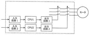
- the control device 20 includes an input unit 30, a blocking unit 31, a load unit 32, a diagnosis unit 33, and an expansion device detector 15. Note that the control device 20 is shown as an example of a configuration in which the input unit 30 to the blocking unit 31 and the load unit 32 are duplicated. However, for a system that does not require high reliability, redundancy is provided. It is possible to configure with one system without performing it.
- the load unit 32 includes load circuits 13a and 13b, and is a circuit for operating the control device 20, such as a motor driver or a signal processing circuit.
- the shut-off unit 31 is composed of the synthesis circuits 6a and 6b and the shut-off circuits 5a and 5b, and switches between supply and cut-off of power to the load unit 32.
- the shut-off circuits 5a and 5b are circuits that supply or shut off the power for operating the load circuits 13a and 13b, and switch the power supply / shut-off in response to a command from a synthesis circuit to be described later.
- the synthesis circuits 6a and 6b receive an external stop signal output from the input unit 30 and a diagnostic signal to be described later, and output a power supply / interruption command to the cutoff circuits 5a and 5b.
- the input unit 30 includes input circuits 7a and 7b, takes in a stop signal input from the outside by digital filter processing, and outputs a stop signal to the synthesis circuits 6a and 6b.
- the diagnostic unit 33 includes a first diagnostic pulse generator 8a and a first cutoff diagnostic device 9a.
- the first diagnostic pulse generator 8a periodically generates a diagnostic signal indicating that the supply of power to the load unit 32 is cut off. This diagnostic signal is input to the synthesis circuits 6a and 6b, and the power supply / cutoff by the cutoff circuits 5a and 5b is controlled.
- the first interruption diagnostic device 9 a detects the supply voltage to the load unit 32. More specifically, the first shutoff diagnostic device 9a performs normal / abnormal diagnosis by detecting the power supply output from the shutoff circuits 5a and 5b.
- the expansion device detector 15 detects whether or not the expansion device 21 is connected to the control device 20. More specifically, the expansion device detector 15 detects whether or not the expansion device 21 is connected, and transmits information about the presence or absence of connection to the first diagnostic pulse generator 8a and the first cutoff diagnostic device 9a.
- control device 20 The above is the configuration of the control device 20. Next, the operation of the expansion device 21 will be described.
- the expansion device 21 includes a second diagnostic pulse generator 8b, a second cutoff diagnostic device 9b, input circuits 7c and 7d, and a monitor / decision device 16.
- the second diagnostic pulse generator 8b periodically generates a diagnostic signal.
- This diagnostic signal is input to the combining circuits 6a and 6b of the control device 20 via the monitoring / determining device 16 described later, and the supply / cutoff of power by the cutoff circuits 5a and 5b is controlled.
- the second shutoff diagnostic device 9b detects the supply voltage to the load unit 32. More specifically, the second shutoff diagnosing device 9b performs normal / abnormal diagnosis by detecting the power supply output from the shutting circuits 5a and 5b.
- the input circuits 7c and 7d take in monitor signals input from outside by digital filter processing.
- the monitoring determinator 16 monitors the operation of the load circuits 13a and 13b when receiving the monitoring signal from the input circuits 7c and 7d, and controls when the monitoring determinator 16 determines that the operation is not set in advance.
- a stop signal for shutting off the power supply to the load circuits 13a and 13b is output to the synthesis circuits 6a and 6b of the apparatus 20.
- the monitoring / determining unit 16 When receiving the diagnostic signal from the second diagnostic pulse generator 8b described above, the monitoring / determining unit 16 outputs the diagnostic signal to the synthesis circuits 6a and 6b. It should be noted that the stop signal and the diagnostic signal of the monitor / determination unit 16 are processed with priority.
- the first diagnostic pulse generator 8a When the expansion device detector 15 detects that the expansion device 21 is not connected to the control device 20, the first diagnostic pulse generator 8a outputs a diagnostic signal to the blocking unit 31 and blocks The unit 31 cuts off the supply of power to the load unit 32 in response to the diagnostic signal output from the first diagnostic pulse generator 8a, and the first cutoff diagnostic unit 9a supplies the load unit 32 to be detected. Based on the voltage, the presence or absence of a failure related to the blocking unit 31 is diagnosed. More specifically, in the above case, the diagnostic device 1 performs the operation described below.
- the expansion device detector 15 detects that the expansion device 21 is not connected to the control device 20, the expansion device detector 15 is not connected to the first diagnostic pulse generator 8a and the first cutoff diagnostic device 9a. By outputting a signal, the controller 20 is informed that it is operating alone.
- the output of the expansion device detector 15 in FIG. 2 is H, it is an operation waveform set by the expansion device 21 to be unconnected.
- the first diagnostic pulse generator 8a outputs a diagnostic signal (L pulse) to the synthesis circuits 6a and 6b, so that the synthesis circuits 6a and 6b send signals to the subsequent cutoff circuits 5a and 5b.
- the shut-off circuits 5a and 5b shut off the supply of power according to the diagnostic signal.
- the power supply to the load circuit 13a and the load circuit 13b is prevented from being cut off simultaneously.
- the first cutoff diagnostic device 9a detects an abnormality
- the first cutoff diagnostic device 9a outputs a power cutoff command to the first diagnostic pulse generator 8a
- the first diagnostic pulse generator 8a outputs the synthesis circuit 6a.
- 6b are simultaneously set to L level to stop the power supply to the load circuit and stop the operation of the load unit 32.
- the second diagnostic pulse generator 8b When the expansion device detector 15 detects that the expansion device 21 is connected to the control device 20, the second diagnostic pulse generator 8b outputs a diagnostic signal to the blocking unit 31 and blocks The unit 31 cuts off the supply of power to the load unit 32 in response to the diagnostic signal output from the second diagnostic pulse generator 8b, and the second cutoff diagnostic unit 9b supplies to the load unit 32 to be detected. Based on the voltage, the presence or absence of a failure related to the blocking unit 31 is diagnosed. More specifically, in the above case, the diagnostic device 1 performs the operation described below.
- the expansion device detector 15 detects that the expansion device 21 is connected to the control device 20, the expansion device detector 15 sends a connection signal to the first diagnostic pulse generator 8a and the first cutoff diagnostic device 9a. To indicate that the expansion device 21 is connected.
- the output signal of the expansion device detector 15 in FIG. 2 is L, the operation waveform is set so that the expansion device 21 is connected.
- the first diagnostic pulse generator 8a of the control device 20 receives the connection signal indicating that the expansion device 21 is connected from the expansion device detector 15, the first diagnostic pulse generator 8a stops generating the diagnostic signal.
- the second diagnostic pulse generator 8 b of the expansion device 21 outputs a diagnostic signal to the monitoring determiner 16.
- the monitor / determination unit 16 outputs a diagnostic signal (L pulse) to the synthesis circuits 6a and 6b, and the subsequent cutoff circuits 5a and 5b cut off the supply of power in accordance with the diagnostic signal.
- a diagnostic signal L pulse
- the subsequent cutoff circuits 5a and 5b cut off the supply of power in accordance with the diagnostic signal.
- the second interruption diagnostic device 9b When the second interruption diagnostic device 9b detects an abnormality, the second interruption diagnostic device 9b outputs a power interruption command to the second diagnostic pulse generator 8b, and the second diagnostic pulse generator 8b By outputting the stop signal to 16, the signals to the synthesis circuits 6a and 6b are simultaneously set to the L level, the power supply to the load circuit is stopped, and the operation of the load unit 32 is stopped.
- the expansion device detector 15 detects the presence / absence of the connection of the expansion device 21 to switch the diagnosis method, thereby facilitating diagnosis of the blocking unit 31 from the expansion device 21.
- the diagnostic operation when the expansion device detector 15 erroneously detects whether or not the expansion device 21 is connected will be described.
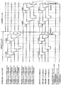
- FIG. 3 shows the operation according to the combination pattern of the results of the expansion device 21 and the expansion device detector 15, and shows the connection state of the expansion device 21 and the state in which the expansion device detector 15 determines the presence or absence of the expansion device 21. ing. Since the patterns [I] and [IV] are normal combinations and the operation of the diagnosis method is as described above, the operations of both [II] and [III] will be described here.
- the first diagnostic pulse generator 8a of the control device 20 determines that the control device 20 is operating alone, it generates a diagnostic signal for the synthesis circuits 6a and 6b.
- the second diagnostic pulse generator 8b of the expansion device 21 also generates a diagnostic signal for the synthesis circuits 6a and 6b via the monitoring / determining unit 16.
- the first cutoff diagnostic device 9a and the second cutoff diagnostic device B9b are at an unexpected timing.
- the H / L of the power supply is detected, it is determined that there is an abnormality, an abnormality signal is output to the diagnostic pulse generator 8a, and the operation of the load unit 32 is stopped.
- diagnosis can be performed in an appropriate region by switching the diagnosis path even when the expansion device 21 is switched between connected and unconnected.
- the first diagnostic pulse generator 8a and the second diagnostic pulse generator 8b have different periods or different phases with respect to the blocking unit 31. By outputting a diagnostic signal, a combination abnormality can be easily detected.
- FIG. 4 is a block diagram of the diagnostic device 1a according to the second embodiment
- FIG. 5 shows an operation based on the combination pattern of the results of the expansion device 21 and the expansion device detector 15, which is different from FIG. 1 of the first embodiment.
- the third shutoff diagnostic device 9c of the control device 20 is configured to monitor the diagnostic signal from the monitoring / determining device 16 of the expansion device 21, and the operation will be described below.
- the third interruption diagnosis device 9c of the second embodiment is the same as that of the first embodiment when the control device 20 operates alone.
- the third shutoff diagnostic device 9c monitors the diagnostic signal from the monitoring / determining device 16 of the expansion device 21.
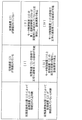
- FIG. 5 shows an operation based on the combination pattern of the results of the expansion device 21 and the expansion device detector 15, and shows the connection state of the expansion device 21a and the state in which the expansion device detector 15 determines the presence or absence of the expansion device 21. ing.
- the patterns [I], [III] and [IV] are the same as those in the first embodiment, and the operation of [II] will be described.
- the expansion device detector 15 determines that the expansion device 21 is connected [II]
- the first diagnostic pulse generator 8a of the control device 20a is connected to the expansion device 21. Therefore, no diagnostic signal is generated.
- the third shutoff diagnostic device 9c monitors the diagnostic signal from the monitoring / determining device 16 of the expansion device 21, but since the expansion device 21 is not actually connected, the diagnostic signal cannot be detected. 9c diagnoses an abnormality, and outputs an abnormal signal to the first diagnostic pulse generator 8a, and the second cutoff diagnostic device B9b outputs an abnormal signal to the second diagnostic pulse generator 8b, and operates the load unit 32. Stop.
- the third cutoff diagnostic device 9c is output from the second diagnostic pulse generator 8b.
- the presence or absence of a failure related to the expansion device 21 is diagnosed based on whether or not a diagnostic signal is detected.
- the input circuits 7c and 7d of the expansion device 21 have two inputs, a plurality of input circuits may be provided to set the contents monitored by the monitoring determiner 16 for each external input signal.
- the third interruption diagnostic device 9c monitors whether the diagnostic signal from the monitoring / determining device 16 of the expansion device 21 is periodically output. Abnormalities in the diagnostic function can be easily detected.
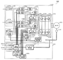
- FIGS. 6, 7, and 8. 6 is a block configuration diagram of the diagnostic apparatus 100 according to the third embodiment
- FIG. 7 is an operation waveform diagram of the diagnostic apparatus 100
- FIG. 8 illustrates an operation based on a combination pattern of the results of the expansion apparatus 121 and the expansion apparatus detector 115. Each operation will be described below.
- the diagnostic device 100 includes a motor control device 110, an expansion device 121 that can be connected to the motor control device 110, a motor 102, and an encoder 118. Each configuration will be described below.
- Reference numeral 118 denotes an encoder which is attached to the motor shaft and detects the rotational position of the motor shaft.
- Reference numeral 101 denotes an inverter circuit that controls a voltage applied to the motor 102 by PWM (Pulse Width Modulation) control. More specifically, the inverter circuit 101 is a three-phase inverter circuit, and has six power elements.
- the P-side power element 103a connected to the positive side (P side) of the main power supply voltage, the main power supply voltage It is comprised by the N side power element 103b connected to the minus side (N side).
- the drive circuit 104 includes a P-side drive circuit 104a and an N-side drive circuit 104b, and drives the inverter circuit 101.
- the cut-off circuit 131 includes cut-off circuits 105a, 105b, 105c, and 105d, and switches between supply and cut-off of power to the drive circuit 104. More specifically, the cutoff circuits 105a and 105c switch between supply and cutoff of power to the P-side drive circuit 104a, and the cutoff circuits 105b and 105d switch between supply and cutoff of power to the N-side drive circuit 104b. Switch.
- the P-side drive circuit 104a controls ON / OFF of the P-side power element 103a, and transmits a PWM signal from a PWM generator (not shown) to the P-side power element 103a.
- the N-side drive circuit 104b performs ON / OFF control of the N-side power element 103b and transmits a PWM signal from a PWM generator (not shown) to the N-side power element 103b.
- the P-side drive circuit 104a and the N-side drive circuit 104b are a high-voltage primary circuit such as the inverter circuit 101 and a low-voltage secondary circuit such as a control signal or an external connection element. Insulating elements such as optocouplers are also used.
- the operating power used in the P-side drive circuit 104a is supplied from the shut-off circuit 105a or 105c. When the operating power is supplied from at least one of the shut-off circuits, the P-side drive circuit 104a operates, and both the shut-off circuits 105a and 105c
- the P-side drive circuit 104a is configured to be ORed so that the operation power supply can be shut off by the circuit.
- This configuration can be easily configured by using two diodes, using each cathode terminal as an operating power supply to the optocoupler, and connecting the anode terminal to each of the cutoff circuits 5a and 5c.
- the N-side circuit has a similar configuration.
- a first diagnostic pulse generator 108a is a diagnostic signal indicating that power supply to the drive circuit 104 is periodically interrupted as shown in FIG. 7 in order to confirm that the cutoff circuit 131 operates correctly. Is generated.
- the diagnosis signal may be generated within the MTFB (mean failure time) of the cutoff circuit 131, but the diagnosis signal may be diagnosed at intervals of 1 minute in order to improve reliability.
- the 109a is a first shutoff diagnostic device that detects the supply voltage to the drive circuit 104. More specifically, the power supply output from the cutoff circuits 105a, 105b, 105c, and 105d is detected, and the result is output to the diagnostic pulse generator. Then, the first interruption diagnosing device 109a diagnoses the presence / absence of a failure relating to the interruption circuit 131 based on the supply voltage to the drive circuit 104 to be detected. Further, the first diagnostic pulse generator 108a may be configured to diagnose a failure relating to the cutoff circuit 131 based on information on the operating power supply from the first cutoff diagnostic unit 109a.
- 107a and 107b are emergency stop signal input circuits, and are configured by redundant circuits using a plurality of signals and circuits in order to increase reliability.
- FIG. 6 shows an example in which the input circuit has two systems, a plurality of configurations of three or more systems may be used.
- the emergency stop signal to the plurality of input circuits simultaneously gives an emergency stop signal to each input circuit when the motor 102 is stopped.
- 106a, 106b, 106c and 106d are synthesis circuits which synthesize the emergency stop signal from the input circuits 107a and 107b and the diagnostic signal from the first diagnostic pulse generator 108a and output a stop signal to each cutoff circuit.
- the circuit configuration of the synthesis circuit is determined by the logic of the emergency stop signal of the input signal. For example, when H is emergency stop, the shut-off circuit is shut off with H as an OR, and when L is emergency stop, the shut-off circuit is L as a logical product. It is possible to configure so that all the interruption circuits are interrupted with respect to an emergency stop signal from the outside.
- the 115 is an expansion device detector that detects whether or not the expansion device 121 is connected to the motor control device 110. Then, information about the presence / absence of connection is transmitted to the first diagnostic pulse generator 108a and the first cutoff diagnostic device 109a.
- the expansion device 121 is a device for extending the monitoring function, and is a device for monitoring the speed or position of the motor shaft by a monitoring signal from the outside.
- 107c and 107d are monitor signal input circuits, which are composed of redundant circuits using a plurality of signals and circuits in order to increase reliability.
- FIG. 6 shows an example in which the input circuit has two systems, a plurality of configurations of three or more systems may be used.
- the monitoring signal to the plurality of input circuits is simultaneously given to each input circuit.
- 117 is an encoder receiver that receives the rotational position information of the motor shaft from the encoder 118 and converts it into rotational speed, rotational position, or rotational amount information of the motor shaft.
- the rotational position information from the encoder 118 serial communication, a two-phase pulse signal with a 90 ° phase difference, a two-phase sine wave signal with a 90 ° phase difference, or the like is used.
- Reference numeral 116b denotes a monitoring / determining device B.
- a monitoring signal is received from the input circuits 107c and 107d, it monitors whether or not the motor 102 is operating within a preset limit. If the limit is exceeded, motor control is performed. A command to shut off the power is output to the synthesis circuits 106a, 106b, 106c and 106d of the apparatus 110.
- the operation of the motor 102 can be detected by using the rotational speed, rotational position, or rotational amount information of the motor shaft converted by the encoder receiver 117.
- the 108b is a second diagnostic pulse generator that periodically generates a diagnostic signal as shown in FIG. 7 in order to confirm that the cutoff circuit 131 operates correctly.
- the diagnosis signal may be generated within the MTFB (mean failure time) of the cutoff circuit 131, but the diagnosis signal may be diagnosed at intervals of 1 minute in order to improve reliability.
- 109b is a second shutoff diagnostic device that detects the supply voltage to the drive circuit 104. More specifically, the power supply output from the cutoff circuits 105a, 105b, 105c, and 105d is detected, and the result is output to the second diagnostic pulse generator 108b. Then, the second interruption diagnosing device 109b diagnoses the presence or absence of a failure relating to the interruption circuit 131 based on the supply voltage to the drive circuit 104 to be detected. Further, the second diagnostic pulse generator 108b may be configured to diagnose the presence or absence of a failure related to the cutoff circuit 131 based on the information of the operating power supply from the second cutoff diagnostic unit 109b.
- the first diagnostic pulse generator 108a When the expansion device detector 115 detects that the expansion device 121 is not connected to the motor control device 110, the first diagnostic pulse generator 108a outputs a diagnostic signal to the cutoff circuit 131, The shut-off circuit 131 shuts off the supply of power to the drive circuit 104 in response to the diagnostic signal output from the first diagnostic pulse generator 108a, and the first shut-off diagnostic unit 109a applies to the drive circuit 104 to be detected. Based on the supply voltage, the presence or absence of a failure relating to the cutoff circuit 131 is diagnosed. More specifically, in the above case, the diagnostic apparatus 100 performs the operation described below.
- the expansion device detector 115 detects that the expansion device 121 is not connected to the motor control device 110, the expansion device detector 115 is not connected to the first diagnostic pulse generator 108a and the first cutoff diagnostic device 109a. By outputting a signal, it is reported that the motor control device 110 is operating alone.
- the output of the expansion device detector 115 in FIG. 7 is H, it is an operation waveform set by the expansion device 121 to be unconnected. As shown in FIG.
- the first diagnostic pulse generator 108a outputs a diagnostic signal (L pulse) to the synthesis circuits 106a, 106b, 106c and 106d, so that the synthesis circuits 106a, 106b, 106c and 106d Signals are output to the shut-off circuits 105a, 105b, 105c and 105d, and the shut-off circuits 105a, 105b, 105c and 105d shut off the supply of power in accordance with the diagnostic signal.
- the power supply to the P-side drive circuit 104a is prevented from being shut off.
- the diagnosis signal to the synthesis circuit 106b and the synthesis circuit 106d is alternately output, thereby preventing the power supply of the N-side drive circuit 104b from being cut off. If the first shutoff diagnostic device 109a detects an abnormality, the first shutoff diagnostic device 109a outputs a power shutoff command to the first diagnostic pulse generator 108a, and the first diagnostic pulse generator 108a outputs the combining circuit 106a. , 106b, 106c, and 106d are simultaneously set to the L level to stop the power supply to the P-side drive circuit 104a and the N-side drive circuit 104b and to stop energization of the motor 102.
- the second diagnostic pulse generator 108b When the expansion device detector 115 detects that the expansion device 121 is connected to the motor control device 110, the second diagnostic pulse generator 108b outputs a diagnostic signal to the cutoff circuit 131, The shut-off circuit 131 shuts off the power supply to the drive circuit 104 in response to the diagnostic signal output from the second diagnostic pulse generator 108b, and the second shut-off diagnostic unit 109b supplies the detected drive circuit 104 to the drive circuit 104. Based on the supply voltage, the presence or absence of a failure relating to the cutoff circuit 131 is diagnosed. More specifically, more specifically, in the above case, the diagnostic device 100 performs the operation described below.
- the expansion device detector 115 detects that the expansion device 121 is connected to the motor control device 110, the expansion device detector 115 is connected to the first diagnostic pulse generator 108a and the first cutoff diagnostic device 109a. By outputting a signal, it is notified that the expansion device 121 is connected.
- the output signal of the expansion device detector 115 in FIG. 7 is L, the operation waveform is set so that the expansion device 121 is connected.
- the first diagnostic pulse generator 108a of the motor control device 110 receives a connection signal indicating that the expansion device 121 is connected from the expansion device detector 115, the first diagnostic pulse generator 108a stops generating the diagnostic signal. .
- FIG. 1 shows a connection signal indicating that the expansion device 121 is connected from the expansion device detector 115.
- the second diagnostic pulse generator 108 b of the expansion device 121 outputs a diagnostic signal to the monitoring determiner 16.
- the monitor / determination unit 16 outputs a diagnostic signal (L pulse) to the synthesis circuits 106a, 106b, 106c, and 106d, and the subsequent cutoff circuits 105a, 105b, 105c, and 105d cut off the supply of power in accordance with the diagnostic signal.
- the diagnosis signal to the synthesis circuit 106b and the synthesis circuit 106d is alternately output, thereby preventing the power supply of the N-side drive circuit 104b from being cut off. If the second cutoff diagnostic unit 109b detects an abnormality, the second cutoff diagnostic unit 109b outputs a power cutoff command to the second diagnostic pulse generator 108b, and the second diagnostic pulse generator 108b By outputting a stop signal to 116, the signals to the synthesis circuits 106a, 106b, 106c and 106d are simultaneously set to the L level, thereby stopping the power supply to the P-side drive circuit 104a and the N-side drive circuit 104b. The energization of power to 102 is stopped.
- the expansion device detector 115 detects whether or not the expansion device 121 is connected, thereby switching the diagnosis method, thereby facilitating diagnosis of the cutoff circuit 131 from the expansion device 121.
- a diagnostic operation when the expansion device detector 115 erroneously detects whether or not the expansion device 121 is connected will be described.
- FIG. 8 is a combination pattern of the results of the expansion device 121 and the expansion device detector 115, showing a connection state of the expansion device 121 and a state in which the expansion device detector 115 determines whether or not the expansion device 121 is present. Since the patterns [I] and [IV] are normal combinations and the operation of the diagnosis method is as described above, the operations of both [II] and [III] will be described here.
- the expansion device 121 is connected and the expansion device detector 115 determines that the expansion device 121 is not connected. Since the first diagnostic pulse generator 108a of the motor control device 110 determines that the motor control device 110 is operating alone, it generates a diagnostic signal for the synthesis circuits 106a, 106b, 106c and 106d. The second diagnostic pulse generator 108b of the expansion device 121 also generates a diagnostic signal for the synthesis circuits 106a, 106b, 106c, and 106d via the monitoring / determining unit 116.
- the first cutoff diagnostic unit 109a and the second cutoff diagnostic unit 109b are at an unexpected timing.
- the H / L of the power supply is detected, it is determined that there is an abnormality, an abnormality signal is output to the first diagnostic pulse generator 108a, and the power supply to the motor 102 is stopped.
- the expansion device detector 115 determines that the expansion device 121 is connected [II]. Since the first diagnostic pulse generator 108a of the motor control device 110 determines that the expansion device 121 is connected, no diagnostic signal is generated. Further, since the expansion device 121 is not actually connected, the diagnosis of the cutoff circuit 131 is not performed. On the other hand, since the power supply of the P-side drive circuit 104a and the N-side drive circuit 104b remains H, the first cutoff diagnostic unit 109a outputs an abnormal signal to the first diagnostic pulse generator 108a. In addition, the second cutoff diagnostic device 109b outputs an abnormal signal to the second diagnostic pulse generator 108b, and stops energizing the motor 102.
- diagnosis can be performed in an appropriate region by switching the diagnosis path even when the expansion device 121 is switched between connected and unconnected.
- the first diagnostic pulse generator 108a and the second diagnostic pulse generator 108b have different periods or different phases with respect to the cutoff circuit 131. By outputting a diagnostic signal, a combination abnormality can be easily detected.
- FIG. 9 is a block diagram of the diagnostic device 100a in the fourth embodiment
- FIG. 10 shows an operation according to the combination pattern of the results of the expansion device 121 and the expansion device detector 115, which is different from FIG. 6 of the first embodiment.
- the third shutoff diagnostic device 109c of the motor control device 110 is configured to monitor the diagnostic signal from the monitoring / determining device 116 of the expansion device 121. The operation will be described below. .
- the third interruption diagnostic device 109c of the fourth embodiment is the same as that of the third embodiment when the motor control device 110 operates alone.
- the third shutoff diagnostic unit 109c monitors the diagnostic signal from the monitoring / determination unit 116 of the expansion device 121.
- FIG. 10 is a combination pattern of the results of the expansion device 121 and the expansion device detector, and shows a connection state of the expansion device 121 and a state in which the expansion device detector 115 determines whether or not the expansion device 121 is present.
- the patterns [I], [III] and [IV] are the same as those in the first embodiment, and the operation of [II] will be described.
- the expansion device detector 115 determines that the expansion device 121 is connected [II]
- the first diagnostic pulse generator 108a of the motor control device 110a is connected to the expansion device 121. Therefore, no diagnostic signal is generated.
- the third cutoff diagnostic device 109c monitors the diagnostic signal from the monitoring / determining device 16 of the expansion device 121. However, since the expansion device 121 is not actually connected, the diagnostic signal cannot be detected. 109c diagnoses an abnormality and outputs an abnormal signal to the first diagnostic pulse generator 108a, and the second shutoff diagnostic unit 109b outputs an abnormal signal to the second diagnostic pulse generator 108b, and the electric power to the motor 102 is output. Stop energization.
- the input circuits 107c and 107d of the expansion device 121 have two inputs, a plurality of input circuits may be provided to set the contents monitored by the monitoring determiner 116 for each external input signal.
- the third shutoff diagnostic unit 109c monitors whether the diagnostic signal from the monitoring / determining unit 116 of the expansion device 121 is periodically output. Abnormalities in the diagnostic function can be easily detected.
- the present invention can be widely used for diagnostic devices for diagnosing the presence or absence of circuit abnormality.
Landscapes
- Engineering & Computer Science (AREA)
- Physics & Mathematics (AREA)
- General Physics & Mathematics (AREA)
- Power Engineering (AREA)
- Automation & Control Theory (AREA)
- Control Of Electric Motors In General (AREA)
- Testing Electric Properties And Detecting Electric Faults (AREA)
- Electric Propulsion And Braking For Vehicles (AREA)
- Inverter Devices (AREA)
- Safety Devices In Control Systems (AREA)
- Testing Of Short-Circuits, Discontinuities, Leakage, Or Incorrect Line Connections (AREA)
Abstract
Description
本実施の形態1に係る診断装置1について、図1、図2および図3を用いて説明する。
図4、図5を用いて本発明の実施の形態2について説明する。図4は実施の形態2における診断装置1aのブロック構成図、図5は拡張装置21と拡張装置検出器15の結果の組み合わせパターンによる動作を示すものであり、実施の形態1の図1と異なるのは拡張装置21が接続され場合、制御装置20の第3遮断診断器9cは拡張装置21の監視判定器16からの診断信号を監視するように構成したところであり、以下に動作を説明する。
本実施の形態3に係る診断装置100について、図6、図7および図8を用いて説明する。図6は実施の形態3に係る診断装置100のブロック構成図、図7は診断装置100の動作波形図、図8は拡張装置121と拡張装置検出器115の結果の組み合わせパターンによる動作を示すものであり、以下に各動作について説明する。
図9、図10を用いて本発明の実施の形態4について説明する。図9は実施の形態4における診断装置100aのブロック構成図、図10は拡張装置121と拡張装置検出器115の結果の組み合わせパターンによる動作を示すものであり、実施の形態1の図6と異なるのは拡張装置121が接続され場合、モータ制御装置110の第3遮断診断器109cは拡張装置121の監視判定器116からの診断信号を監視するように構成したところであり、以下に動作を説明する。
8a、108a 第1診断パルス生成器
8b、108b 第2診断パルス生成器
9a、109a 第1遮断診断器
9b、109b 第2遮断診断器
9c、109c 第3遮断診断器
15、115 拡張装置検出器
20、20a 制御措置
21、21a、121、121a 拡張装置
31 遮断部
32 負荷部
101 インバータ回路
102 モータ
104 駆動回路
105a、105b、105c、105d、131 遮断回路
110、110a モータ制御装置
Claims (6)
- 制御装置と、
前記制御装置に接続可能な拡張装置とを備え、
前記制御装置は、
負荷部への電力の供給と遮断とを切り替える遮断部と、
前記負荷部への電力の供給を遮断する旨を示す診断信号を生成する第1診断パルス生成器と、
前記負荷部への供給電圧を検出する第1遮断診断器と、
前記制御装置に前記拡張装置が接続されているか否かを検出する拡張装置検出器とを含み、
前記拡張装置は、
前記診断信号を生成する第2診断パルス生成器と、
前記負荷部への供給電圧を検出する第2遮断診断器とを含み、
前記拡張装置検出器によって、前記制御装置に前記拡張装置が接続されていないことが検出される場合には、
前記第1診断パルス生成器は、前記遮断部に対して前記診断信号を出力し、
前記遮断部は、前記第1診断パルス生成器から出力される前記診断信号に呼応して、前記負荷部への電力の供給を遮断し、
前記第1遮断診断器は、検出する前記負荷部への供給電圧に基づいて、前記遮断部に係る故障の有無を診断し、
前記拡張装置検出器によって、前記制御装置に前記拡張装置が接続されていることが検出される場合には、
前記第2診断パルス生成器は、前記遮断部に対して前記診断信号を出力し、
前記遮断部は、前記第2診断パルス生成器から出力される前記診断信号に呼応して、前記負荷部への電力の供給を遮断し、
前記第2遮断診断器は、検出する前記負荷部への供給電圧に基づいて、前記遮断部に係る故障の有無を診断する
ことを特徴とする診断装置。 - 前記第1診断パルス生成器と、前記第2診断パルス生成器とは、前記遮断部に対して、互いに異なる周期、あるいは互いに異なる位相で前記診断信号を出力する
ことを特徴とする請求項1に記載の診断装置。 - 前記拡張装置検出器によって、前記制御装置に前記拡張装置が接続されていることが検出される場合には、前記第1遮断診断器は、さらに、前記第2診断パルス生成器から出力される前記診断信号を検出するか否かに基づいて、前記拡張装置に係る故障の有無を診断する
ことを特徴とする請求項1又は2に記載の診断装置。 - モータ制御装置と、
前記モータ制御装置に接続可能な拡張装置とを備え、
前記モータ制御装置は、
PWM(Pulse Width Modulation)制御によりモータへ印加する電圧を制御するインバータ回路と、
前記インバータ回路を駆動する駆動回路と、
前記駆動回路への電力の供給と遮断とを切り替える遮断回路と、
前記駆動回路への電力の供給を遮断する旨を示す診断信号を生成する第1診断パルス生成器と、
前記駆動回路への供給電圧を検出する第1遮断診断器と、
前記モータ制御装置に前記拡張装置が接続されているか否かを検出する拡張装置検出器とを含み、
前記拡張装置は、
前記診断信号を生成する第2診断パルス生成器と、
前記駆動回路への供給電圧を検出する第2遮断診断器とを含み、
前記拡張装置検出器によって、前記モータ制御装置に前記拡張装置が接続されていないことが検出される場合には、
前記第1診断パルス生成器は、前記遮断回路に対して前記診断信号を出力し、
前記遮断回路は、前記第1診断パルス生成器から出力される前記診断信号に呼応して、前記駆動回路への電力の供給を遮断し、
前記第1遮断診断器は、検出する前記駆動回路への供給電圧に基づいて、前記遮断回路に係る故障の有無を診断し、
前記拡張装置検出器によって、前記モータ制御装置に前記拡張装置が接続されていることが検出される場合には、
前記第2診断パルス生成器は、前記遮断回路に対して前記診断信号を出力し、
前記遮断回路は、前記第2診断パルス生成器から出力される前記診断信号に呼応して、前記駆動回路への電力の供給を遮断し、
前記第2遮断診断器は、検出する前記駆動回路への供給電圧に基づいて、前記遮断回路に係る故障の有無を診断する
ことを特徴とする診断装置。 - 前記第1診断パルス生成器と、前記第2診断パルス生成器とは、前記遮断回路に対して、互いに異なる周期、あるいは互いに異なる位相で前記診断信号を出力する
ことを特徴とする請求項4に記載の診断装置。 - 前記拡張装置検出器によって前記モータ制御装置に前記拡張装置が接続されていることが検出される場合には、前記第1遮断診断器は、さらに、前記第2診断パルス生成器から出力される前記診断信号を検出するか否かに基づいて、前記拡張装置に係る故障の有無を診断する
ことを特徴とする請求項4又は5に記載の診断装置。
Priority Applications (5)
| Application Number | Priority Date | Filing Date | Title |
|---|---|---|---|
| EP18809353.8A EP3633465B1 (en) | 2017-05-31 | 2018-04-17 | Diagnostic apparatus |
| US16/617,405 US11293997B2 (en) | 2017-05-31 | 2018-04-17 | Diagnostic apparatus |
| CN201880034404.9A CN110678815B (zh) | 2017-05-31 | 2018-04-17 | 诊断装置 |
| KR1020197034901A KR102413474B1 (ko) | 2017-05-31 | 2018-04-17 | 진단 장치 |
| JP2019522016A JP7054849B2 (ja) | 2017-05-31 | 2018-04-17 | 診断装置 |
Applications Claiming Priority (2)
| Application Number | Priority Date | Filing Date | Title |
|---|---|---|---|
| JP2017-108699 | 2017-05-31 | ||
| JP2017108699 | 2017-05-31 |
Publications (1)
| Publication Number | Publication Date |
|---|---|
| WO2018221043A1 true WO2018221043A1 (ja) | 2018-12-06 |
Family
ID=64455988
Family Applications (1)
| Application Number | Title | Priority Date | Filing Date |
|---|---|---|---|
| PCT/JP2018/015783 WO2018221043A1 (ja) | 2017-05-31 | 2018-04-17 | 診断装置 |
Country Status (6)
| Country | Link |
|---|---|
| US (1) | US11293997B2 (ja) |
| EP (1) | EP3633465B1 (ja) |
| JP (1) | JP7054849B2 (ja) |
| KR (1) | KR102413474B1 (ja) |
| CN (1) | CN110678815B (ja) |
| WO (1) | WO2018221043A1 (ja) |
Cited By (1)
| Publication number | Priority date | Publication date | Assignee | Title |
|---|---|---|---|---|
| TWI728626B (zh) * | 2019-01-10 | 2021-05-21 | 日商日立產機系統股份有限公司 | 電力轉換裝置、旋轉機系統、及診斷方法 |
Families Citing this family (3)
| Publication number | Priority date | Publication date | Assignee | Title |
|---|---|---|---|---|
| JP7398620B2 (ja) * | 2018-06-15 | 2023-12-15 | パナソニックIpマネジメント株式会社 | 遮断回路診断装置 |
| US11309823B2 (en) * | 2020-07-02 | 2022-04-19 | Yefim Tservil | Three phase motor control with variable RPM and variable synchronized PWM |
| EP4163739B1 (de) * | 2021-10-05 | 2024-01-31 | B&R Industrial Automation GmbH | Verfahren zur überwachung einer elektrischen schaltanordnung |
Citations (3)
| Publication number | Priority date | Publication date | Assignee | Title |
|---|---|---|---|---|
| JP2001183207A (ja) * | 1999-12-27 | 2001-07-06 | Matsushita Electric Ind Co Ltd | ガス安全制御回路 |
| JP2006268130A (ja) | 2005-03-22 | 2006-10-05 | Fanuc Ltd | 非常停止回路 |
| JP2014075105A (ja) * | 2012-10-05 | 2014-04-24 | Hitachi Ltd | 制御システム |
Family Cites Families (28)
| Publication number | Priority date | Publication date | Assignee | Title |
|---|---|---|---|---|
| JP2000088907A (ja) * | 1998-09-17 | 2000-03-31 | Nissan Motor Co Ltd | 負荷診断回路 |
| AU2002216528A1 (en) * | 2000-12-15 | 2002-06-24 | Abb T And D Technology Ltd | Condition diagnosing |
| JP2004213454A (ja) * | 2003-01-07 | 2004-07-29 | Hitachi Ltd | 負荷の故障診断方法および装置 |
| DE102005028184A1 (de) * | 2005-06-17 | 2006-12-21 | Siemens Ag | Schaltungsanordnung mit einem Eigendiagnosesystem zum Ansteuern und Überwachen einer Last in einer Brückenschaltung und dazugehöriges Betriebsverfahren |
| EP1981313A1 (en) * | 2007-04-13 | 2008-10-15 | MAGNETI MARELLI SISTEMI ELETTRONICI S.p.A. | Diagnostic system for external lighting devices of a vehicle |
| CN100578884C (zh) * | 2007-04-13 | 2010-01-06 | 郭振清 | 具有自动负载检测的电力终端保护器 |
| JP2009033835A (ja) * | 2007-07-25 | 2009-02-12 | Tokai Rika Co Ltd | 負荷駆動制御回路 |
| EP2257825B1 (en) * | 2008-03-20 | 2019-01-30 | NXP USA, Inc. | Apparatus and a method for detecting faults in the delivery of electrical power to electrical loads |
| CN102187569B (zh) | 2008-10-15 | 2013-09-25 | 松下电器产业株式会社 | 电机控制装置 |
| JP5370724B2 (ja) | 2008-10-27 | 2013-12-18 | 株式会社安川電機 | 安全停止回路を備えたモータ制御装置 |
| EP2357484B1 (de) * | 2010-01-25 | 2013-03-13 | Siemens Aktiengesellschaft | Verfahren zur Diagnose einer elektrischen Verbindung und Ausgabebaugruppe |
| JP5059894B2 (ja) * | 2010-03-19 | 2012-10-31 | 日立オートモティブシステムズ株式会社 | 燃料ポンプ制御装置 |
| KR101585940B1 (ko) * | 2011-03-03 | 2016-01-18 | 삼성전자 주식회사 | 고장 검출 장치, 전기기기 및 고장 검출 방법 |
| WO2014091581A1 (ja) * | 2012-12-12 | 2014-06-19 | 三菱電機株式会社 | 回路異常検出装置 |
| JP6156689B2 (ja) * | 2013-06-25 | 2017-07-05 | 株式会社Gsユアサ | スイッチ故障診断装置、スイッチ故障診断方法 |
| JP5552564B1 (ja) * | 2013-09-24 | 2014-07-16 | 川崎重工業株式会社 | 多軸ロボットの動力遮断装置及び多軸ロボット |
| WO2015063892A1 (ja) * | 2013-10-30 | 2015-05-07 | 株式会社安川電機 | モータ制御装置 |
| EP2887163B1 (de) * | 2013-12-18 | 2018-01-17 | Festo AG & Co. KG | Überwachungsvorrichtung, Sicherheitssystem und Verfahren zum Betreiben eines Sicherheitssystems |
| DE102015207117A1 (de) * | 2014-07-09 | 2016-01-14 | Siemens Aktiengesellschaft | Umrichter mit redundanter Schaltungstopologie |
| JP6313463B2 (ja) | 2014-10-01 | 2018-04-18 | 株式会社日立産機システム | 電力変換装置、電力変換方法および電力変換システム |
| US9653910B2 (en) * | 2014-11-14 | 2017-05-16 | Rockwell Automation Technologies, Inc. | Power structure diagnostic method and apparatus for improved motor drive diagnostic coverage |
| JP6375908B2 (ja) * | 2014-12-03 | 2018-08-22 | 株式会社デンソー | Dc−dcコンバータの制御装置 |
| US10749430B2 (en) * | 2015-03-13 | 2020-08-18 | Positec Power Tools (Suzhou) Co., Ltd. | Power transmission apparatus and control method therefor, and power supply system |
| WO2017013722A1 (ja) * | 2015-07-17 | 2017-01-26 | 株式会社日立産機システム | 遮断制御方法、及びそれを用いた電力変換装置 |
| US20170083078A1 (en) * | 2015-09-23 | 2017-03-23 | Intel Corporation | High definition multimedia interface power management |
| EP3355462A4 (en) * | 2015-09-25 | 2018-10-17 | Panasonic Intellectual Property Management Co., Ltd. | Motor control device |
| DE102016203355A1 (de) * | 2016-03-01 | 2017-09-07 | Kuka Roboter Gmbh | Elektrische Vorrichtung mit einem getakteten Netzteil und Verfahren zum Überprüfen des Netzteils der elektrischen Vorrichtung |
| JP7398620B2 (ja) * | 2018-06-15 | 2023-12-15 | パナソニックIpマネジメント株式会社 | 遮断回路診断装置 |
-
2018
- 2018-04-17 WO PCT/JP2018/015783 patent/WO2018221043A1/ja active Application Filing
- 2018-04-17 JP JP2019522016A patent/JP7054849B2/ja active Active
- 2018-04-17 US US16/617,405 patent/US11293997B2/en active Active
- 2018-04-17 KR KR1020197034901A patent/KR102413474B1/ko active IP Right Grant
- 2018-04-17 CN CN201880034404.9A patent/CN110678815B/zh active Active
- 2018-04-17 EP EP18809353.8A patent/EP3633465B1/en active Active
Patent Citations (3)
| Publication number | Priority date | Publication date | Assignee | Title |
|---|---|---|---|---|
| JP2001183207A (ja) * | 1999-12-27 | 2001-07-06 | Matsushita Electric Ind Co Ltd | ガス安全制御回路 |
| JP2006268130A (ja) | 2005-03-22 | 2006-10-05 | Fanuc Ltd | 非常停止回路 |
| JP2014075105A (ja) * | 2012-10-05 | 2014-04-24 | Hitachi Ltd | 制御システム |
Non-Patent Citations (1)
| Title |
|---|
| See also references of EP3633465A4 |
Cited By (1)
| Publication number | Priority date | Publication date | Assignee | Title |
|---|---|---|---|---|
| TWI728626B (zh) * | 2019-01-10 | 2021-05-21 | 日商日立產機系統股份有限公司 | 電力轉換裝置、旋轉機系統、及診斷方法 |
Also Published As
| Publication number | Publication date |
|---|---|
| CN110678815B (zh) | 2022-05-31 |
| KR20200013659A (ko) | 2020-02-07 |
| JP7054849B2 (ja) | 2022-04-15 |
| US11293997B2 (en) | 2022-04-05 |
| JPWO2018221043A1 (ja) | 2020-04-02 |
| EP3633465A4 (en) | 2020-05-27 |
| CN110678815A (zh) | 2020-01-10 |
| US20200408852A1 (en) | 2020-12-31 |
| EP3633465A1 (en) | 2020-04-08 |
| EP3633465B1 (en) | 2022-05-04 |
| KR102413474B1 (ko) | 2022-06-27 |
Similar Documents
| Publication | Publication Date | Title |
|---|---|---|
| WO2018221043A1 (ja) | 診断装置 | |
| WO2017159091A1 (ja) | モータ制御装置 | |
| JP5552564B1 (ja) | 多軸ロボットの動力遮断装置及び多軸ロボット | |
| WO2016072432A1 (ja) | モータ駆動装置および電動パワーステアリング装置 | |
| US20020084766A1 (en) | Drive control for a three phase AC motor via an inverter using safe technology | |
| KR101775302B1 (ko) | 전력 차단 장치 | |
| CN112638739B (zh) | 一种冗余电子控制系统及设备 | |
| JP2016096709A (ja) | モータ駆動装置および電動パワーステアリング装置 | |
| JP7398620B2 (ja) | 遮断回路診断装置 | |
| CN107431449B (zh) | 电动机控制装置 | |
| JP6644145B2 (ja) | 産業用ロボットのための電気駆動装置 | |
| JP6010104B2 (ja) | サーボモータ制御装置 | |
| WO2018155510A1 (ja) | モータ制御装置 | |
| JP2023511516A (ja) | モータ制御システム及びモータ制御装置 | |
| JP6984390B2 (ja) | 電力制御ユニット | |
| JP6613849B2 (ja) | ロボット制御装置 | |
| JP2018195128A (ja) | 診断装置 | |
| JP2017169441A (ja) | モータ制御装置 | |
| JPH01255476A (ja) | 電力変換装置の制御装置 | |
| JP2005117704A (ja) | 電動機の駆動システム |
Legal Events
| Date | Code | Title | Description |
|---|---|---|---|
| 121 | Ep: the epo has been informed by wipo that ep was designated in this application |
Ref document number: 18809353 Country of ref document: EP Kind code of ref document: A1 |
|
| ENP | Entry into the national phase |
Ref document number: 2019522016 Country of ref document: JP Kind code of ref document: A |
|
| ENP | Entry into the national phase |
Ref document number: 20197034901 Country of ref document: KR Kind code of ref document: A |
|
| NENP | Non-entry into the national phase |
Ref country code: DE |
|
| WWE | Wipo information: entry into national phase |
Ref document number: 2018809353 Country of ref document: EP |
|
| ENP | Entry into the national phase |
Ref document number: 2018809353 Country of ref document: EP Effective date: 20200102 |