WO2018221014A1 - 内視鏡光源装置 - Google Patents
内視鏡光源装置 Download PDFInfo
- Publication number
- WO2018221014A1 WO2018221014A1 PCT/JP2018/014847 JP2018014847W WO2018221014A1 WO 2018221014 A1 WO2018221014 A1 WO 2018221014A1 JP 2018014847 W JP2018014847 W JP 2018014847W WO 2018221014 A1 WO2018221014 A1 WO 2018221014A1
- Authority
- WO
- WIPO (PCT)
- Prior art keywords
- light
- solid
- light source
- endoscope
- source device
- Prior art date
- Legal status (The legal status is an assumption and is not a legal conclusion. Google has not performed a legal analysis and makes no representation as to the accuracy of the status listed.)
- Ceased
Links
Images







Classifications
-
- G—PHYSICS
- G02—OPTICS
- G02B—OPTICAL ELEMENTS, SYSTEMS OR APPARATUS
- G02B6/00—Light guides; Structural details of arrangements comprising light guides and other optical elements, e.g. couplings
- G02B6/0001—Light guides; Structural details of arrangements comprising light guides and other optical elements, e.g. couplings specially adapted for lighting devices or systems
- G02B6/0005—Light guides; Structural details of arrangements comprising light guides and other optical elements, e.g. couplings specially adapted for lighting devices or systems the light guides being of the fibre type
- G02B6/0006—Coupling light into the fibre
-
- A—HUMAN NECESSITIES
- A61—MEDICAL OR VETERINARY SCIENCE; HYGIENE
- A61B—DIAGNOSIS; SURGERY; IDENTIFICATION
- A61B1/00—Instruments for performing medical examinations of the interior of cavities or tubes of the body by visual or photographical inspection, e.g. endoscopes; Illuminating arrangements therefor
- A61B1/06—Instruments for performing medical examinations of the interior of cavities or tubes of the body by visual or photographical inspection, e.g. endoscopes; Illuminating arrangements therefor with illuminating arrangements
-
- A—HUMAN NECESSITIES
- A61—MEDICAL OR VETERINARY SCIENCE; HYGIENE
- A61B—DIAGNOSIS; SURGERY; IDENTIFICATION
- A61B1/00—Instruments for performing medical examinations of the interior of cavities or tubes of the body by visual or photographical inspection, e.g. endoscopes; Illuminating arrangements therefor
- A61B1/06—Instruments for performing medical examinations of the interior of cavities or tubes of the body by visual or photographical inspection, e.g. endoscopes; Illuminating arrangements therefor with illuminating arrangements
- A61B1/0638—Instruments for performing medical examinations of the interior of cavities or tubes of the body by visual or photographical inspection, e.g. endoscopes; Illuminating arrangements therefor with illuminating arrangements providing two or more wavelengths
-
- A—HUMAN NECESSITIES
- A61—MEDICAL OR VETERINARY SCIENCE; HYGIENE
- A61B—DIAGNOSIS; SURGERY; IDENTIFICATION
- A61B1/00—Instruments for performing medical examinations of the interior of cavities or tubes of the body by visual or photographical inspection, e.g. endoscopes; Illuminating arrangements therefor
- A61B1/06—Instruments for performing medical examinations of the interior of cavities or tubes of the body by visual or photographical inspection, e.g. endoscopes; Illuminating arrangements therefor with illuminating arrangements
- A61B1/0661—Endoscope light sources
- A61B1/0669—Endoscope light sources at proximal end of an endoscope
-
- A—HUMAN NECESSITIES
- A61—MEDICAL OR VETERINARY SCIENCE; HYGIENE
- A61B—DIAGNOSIS; SURGERY; IDENTIFICATION
- A61B1/00—Instruments for performing medical examinations of the interior of cavities or tubes of the body by visual or photographical inspection, e.g. endoscopes; Illuminating arrangements therefor
- A61B1/06—Instruments for performing medical examinations of the interior of cavities or tubes of the body by visual or photographical inspection, e.g. endoscopes; Illuminating arrangements therefor with illuminating arrangements
- A61B1/07—Instruments for performing medical examinations of the interior of cavities or tubes of the body by visual or photographical inspection, e.g. endoscopes; Illuminating arrangements therefor with illuminating arrangements using light-conductive means, e.g. optical fibres
-
- F—MECHANICAL ENGINEERING; LIGHTING; HEATING; WEAPONS; BLASTING
- F21—LIGHTING
- F21S—NON-PORTABLE LIGHTING DEVICES; SYSTEMS THEREOF; VEHICLE LIGHTING DEVICES SPECIALLY ADAPTED FOR VEHICLE EXTERIORS
- F21S2/00—Systems of lighting devices, not provided for in main groups F21S4/00 - F21S10/00 or F21S19/00, e.g. of modular construction
-
- F—MECHANICAL ENGINEERING; LIGHTING; HEATING; WEAPONS; BLASTING
- F21—LIGHTING
- F21V—FUNCTIONAL FEATURES OR DETAILS OF LIGHTING DEVICES OR SYSTEMS THEREOF; STRUCTURAL COMBINATIONS OF LIGHTING DEVICES WITH OTHER ARTICLES, NOT OTHERWISE PROVIDED FOR
- F21V11/00—Screens not covered by groups F21V1/00, F21V3/00, F21V7/00 or F21V9/00
- F21V11/08—Screens not covered by groups F21V1/00, F21V3/00, F21V7/00 or F21V9/00 using diaphragms containing one or more apertures
-
- G—PHYSICS
- G02—OPTICS
- G02B—OPTICAL ELEMENTS, SYSTEMS OR APPARATUS
- G02B19/00—Condensers, e.g. light collectors or similar non-imaging optics
- G02B19/0004—Condensers, e.g. light collectors or similar non-imaging optics characterised by the optical means employed
- G02B19/0009—Condensers, e.g. light collectors or similar non-imaging optics characterised by the optical means employed having refractive surfaces only
- G02B19/0014—Condensers, e.g. light collectors or similar non-imaging optics characterised by the optical means employed having refractive surfaces only at least one surface having optical power
-
- G—PHYSICS
- G02—OPTICS
- G02B—OPTICAL ELEMENTS, SYSTEMS OR APPARATUS
- G02B19/00—Condensers, e.g. light collectors or similar non-imaging optics
- G02B19/0033—Condensers, e.g. light collectors or similar non-imaging optics characterised by the use
- G02B19/0047—Condensers, e.g. light collectors or similar non-imaging optics characterised by the use for use with a light source
- G02B19/0061—Condensers, e.g. light collectors or similar non-imaging optics characterised by the use for use with a light source the light source comprising a LED
-
- G—PHYSICS
- G02—OPTICS
- G02B—OPTICAL ELEMENTS, SYSTEMS OR APPARATUS
- G02B23/00—Telescopes, e.g. binoculars; Periscopes; Instruments for viewing the inside of hollow bodies; Viewfinders; Optical aiming or sighting devices
- G02B23/24—Instruments or systems for viewing the inside of hollow bodies, e.g. fibrescopes
- G02B23/2407—Optical details
- G02B23/2461—Illumination
- G02B23/2469—Illumination using optical fibres
-
- G—PHYSICS
- G02—OPTICS
- G02B—OPTICAL ELEMENTS, SYSTEMS OR APPARATUS
- G02B27/00—Optical systems or apparatus not provided for by any of the groups G02B1/00 - G02B26/00, G02B30/00
- G02B27/09—Beam shaping, e.g. changing the cross-sectional area, not otherwise provided for
- G02B27/0916—Adapting the beam shape of a semiconductor light source such as a laser diode or an LED, e.g. for efficiently coupling into optical fibers
-
- G—PHYSICS
- G02—OPTICS
- G02B—OPTICAL ELEMENTS, SYSTEMS OR APPARATUS
- G02B27/00—Optical systems or apparatus not provided for by any of the groups G02B1/00 - G02B26/00, G02B30/00
- G02B27/10—Beam splitting or combining systems
- G02B27/14—Beam splitting or combining systems operating by reflection only
- G02B27/141—Beam splitting or combining systems operating by reflection only using dichroic mirrors
-
- G—PHYSICS
- G02—OPTICS
- G02B—OPTICAL ELEMENTS, SYSTEMS OR APPARATUS
- G02B27/00—Optical systems or apparatus not provided for by any of the groups G02B1/00 - G02B26/00, G02B30/00
- G02B27/30—Collimators
-
- G—PHYSICS
- G02—OPTICS
- G02B—OPTICAL ELEMENTS, SYSTEMS OR APPARATUS
- G02B6/00—Light guides; Structural details of arrangements comprising light guides and other optical elements, e.g. couplings
- G02B6/24—Coupling light guides
- G02B6/26—Optical coupling means
- G02B6/262—Optical details of coupling light into, or out of, or between fibre ends, e.g. special fibre end shapes or associated optical elements
-
- G—PHYSICS
- G02—OPTICS
- G02B—OPTICAL ELEMENTS, SYSTEMS OR APPARATUS
- G02B6/00—Light guides; Structural details of arrangements comprising light guides and other optical elements, e.g. couplings
- G02B6/24—Coupling light guides
- G02B6/26—Optical coupling means
- G02B6/32—Optical coupling means having lens focusing means positioned between opposed fibre ends
Definitions
- the present invention relates to an endoscope light source device.
- a light source device that emits broadband illumination light by collimating and combining light from a plurality of semiconductor light sources that respectively emit light having different wavelengths (see, for example, Patent Document 1).
- a semiconductor light source such as an LED has an area, it is difficult to generate perfect collimated light, and depending on the light guide diameter provided in the insertion portion of the endoscope due to factors such as different optical path lengths.
- the light transmission efficiency may vary from LED to LED. That is, when scopes with different light guide diameters are combined, the light quantity balance of each color fluctuates based on the difference in light transmission efficiency, so that color reproducibility varies depending on the scope.
- the present invention has been made in view of the circumstances described above, and provides an endoscope light source device that can suppress fluctuations in the light amount balance of light emitted from the distal end of a scope even when combining scopes having different light guide diameters. It is intended to provide.
- One embodiment of the present invention includes a plurality of solid-state light sources, a plurality of collimating lenses that make light emitted from the respective solid-state light sources substantially parallel light, and light that has been made substantially parallel light by the respective collimating lenses.
- An endoscope light source device is provided that includes a condensing lens that collects light from each of the solid light sources and makes the light incident on an end face of a light guide of the endoscope.
- the light respectively emitted from the plurality of solid state light sources is converted into substantially parallel light by the collimating lens, and then combined by the combining optical member and collected by the condensing lens. Is incident on the other surface of the light guide.
- a peripheral light amount from the solid light source is adjusted by the light amount adjusting mechanism disposed between the at least one solid light source and the collimating lens, and is incident on the collimating lens. Thereby, a peripheral light quantity can be adjusted for every solid light source.
- the light amount adjustment mechanism may block more ambient light as the optical path length from each solid light source to the condenser lens is shorter. By doing so, the longer the optical path length, the more ambient light is emitted by the condensing lens.Therefore, unless the light amount adjustment mechanism is arranged, the thicker the light guide of the scope to be attached, the longer the optical path length from the solid light source. The amount of light decreases and the light amount balance becomes worse. By arranging a light amount adjustment mechanism and blocking more ambient light as the light path length is shorter, the light amount balance from a solid light source with a long light path length decreases when the light guide of the attached scope is thick It is possible to keep the light quantity balance constant.
- the light amount adjusting mechanism may be an aperture having a different aperture diameter for each combination of the solid light source and the collimating lens. In this way, the shorter the optical path length is, the smaller the aperture diameter of the stop mounted so as to block the ambient light from the solid state light source. It is possible to prevent the light amount balance of the light from the long solid light source from being lowered, and to maintain the light amount balance constant.
- the light amount adjusting mechanism may be a diaphragm disposed at a different distance from each solid light source for each combination of each solid light source and each collimator lens.
- the stop may satisfy the following conditional expression. ⁇ / L ⁇ 1.5NA ⁇ / ⁇ (1-NA ⁇ ) 2 ) Where ⁇ is the aperture diameter of the stop, NA is the numerical aperture of the light guide, ⁇ is the absolute value of the paraxial magnification when the solid light source forms an image on the light guide, and L is the solid light source and the stop Is the optical path length between.
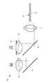
- FIG. 1 It is a mimetic diagram showing an endoscope light source device concerning one embodiment of the present invention.
- the endoscope light source device of FIG. 1 is a diagram showing light rays from each part of an LED by extending a light path on the short side of the optical path length without a diaphragm.
- the light path from the long side of the optical path is straightly extended to show the light rays from each part of the LED.
- an endoscope light source device 10 includes a plurality of LEDs (solid light sources) 1 and 2 that emit light having different wavelengths, and lights emitted from the LEDs 1 and 2.
- a plurality of collimating lenses 11 that make substantially parallel light, a dichroic mirror (combining optical member) 4 that combines the light that has been made substantially parallel by each collimating lens 11, an LED 2 that has a shorter optical path length, and a collimating lens 11 is provided with a diaphragm (light quantity adjusting mechanism) 5 disposed between the two.
- reference numeral 6 denotes a mirror.
- the first light emitted from the LED 1 having the longer optical path length is made substantially parallel light by the collimator lens 11, then deflected by the mirror 6, transmitted through the dichroic mirror 4, and condensed by the condenser lens 7.
- the light enters the incident end of the light guide 8 of the scope 9 of the endoscope.
- the second light emitted from the LED 2 with the shorter optical path length is collimated by the collimating lens 11 and then deflected by the dichroic mirror 4 to be combined with the first light and collected.
- the light is condensed by the optical lens 7 and is incident on the incident end of the light guide 8 of the scope 9 of the endoscope.
- the collimating lenses 11 cannot make perfect collimated light from the light from the LEDs 1 and 2 and the optical path length is short as shown in FIG. 2A.
- the optical path length is longer as shown in FIG. 2B, the ambient light (shaded portion in the figure) is drawn by the condenser lens 7.
- the condenser lens 7 The amount of light of the first light on the side where the optical path length is long is reduced compared to the second light on the side of the short optical path length.
- the endoscope light source device 10 is provided with a diaphragm 5 that blocks ambient light of the second light between the LED 2 on the side with a shorter optical path length and the collimating lens 11. Therefore, by appropriately adjusting the opening area of the diaphragm 5, the ambient light of the second light can be blocked in advance as shown in FIG. That is, even when the scope 9 having the thick light guide 8 that allows the ambient light to enter is attached, as shown in FIG. 5, the optical path length on which the ambient light is scattered by the condenser lens 7 is longer. A decrease in the light amount balance of the first light can be prevented.
- the diaphragm 5 preferably satisfies the following conditional expression (1).
- NA of the light guide 8 is NAlg
- the optical system is efficient when the light is condensed by NAlg. Since light exceeding NAlg cannot be taken in by the light guide 8, it is lost and becomes heat energy.
- conditional expression (2) Substituting conditional expression (2) into conditional expression (3) yields expression (4).
- Conditional expression (1) can be obtained by substituting Expression (5) into Expression (4) and modifying it.
- the light distribution from the endoscope is calculated as shown in FIG.
- the lens data of Example 1 of Japanese Patent No. 0589224 was used as the illumination optical system of the endoscope.
- the present invention may be applied to the case where light from three or more LEDs 1, 2 and 3 are multiplexed.
- the diaphragm 5 may also be arranged between the LED 1 having the longest optical path length and the collimating lens 11.
- the amount of light emitted from the ambient light is adjusted by changing the aperture diameter of the diaphragm 5, but instead of this, as shown in FIG.
- the distance L of the diaphragm 5 from the center may be varied.
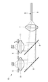
- FIG. 9 A first example of the endoscope light source device 10 according to this embodiment will be described below.
- two LEDs 1 and 2 are provided, and a diaphragm 5 is disposed between each LED 1 and 2 and the collimating lens 11 corresponding thereto.
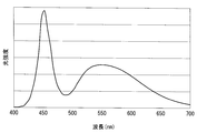
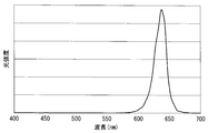
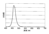
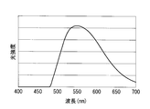
- the LEDs 1 and 2 have the spectral characteristics shown in FIGS. 10A and 10B, the mirror 6 has the reflectance characteristics shown in FIG. 11, and the dichroic mirror 4 has the transmittance characteristics shown in FIG. It is used to emit light having the spectral characteristics shown in FIG.
- the aperture diameter ⁇ of the diaphragm 5 arranged in the optical path having the shorter optical path length is 22 mm
- the distance L is 12.55 mm
- the paraxial magnification absolute value ⁇ is 0.98
- the aperture of the light guide fiber of the endoscope is set.
- FIG. 14 A second example of the endoscope light source device 10 according to this embodiment will be described below.
- three LEDs 1, 2, 3 are provided, and a diaphragm 5 is arranged between each LED 1, 2, 3 and the collimating lens 11 corresponding thereto.
- LEDs 1, 2 and 3 having spectral characteristics shown in FIGS. 15A to 15C are used, dichroic mirror 6 having reflectance characteristics shown in FIG. 16 is used, and dichroic mirror 4 is shown in FIG. 17A.
- light having the transmittance characteristic shown in FIG. 17B is used, and light having the spectral characteristic shown in FIG. 18 is emitted as light emitted from the light source.
- the aperture diameter ⁇ of the diaphragm 5 arranged in the optical path with the longest optical path length is 34 mm, the distance L is 12.55 mm, the paraxial magnification absolute value ⁇ is 0.91, and the numerical aperture of the light guide fiber of the endoscope
- NA 0.5
- ⁇ / L 2.71
- 1.5NA ⁇ / ⁇ (1 ⁇ (NA ⁇ ) 2 ) 0.98, which satisfies the conditional expression (6).
- the aperture diameter ⁇ of the diaphragm 5 arranged in the optical path having the second longest optical path length is 29 mm, the distance L is 12.55 mm, the paraxial magnification absolute value ⁇ is 0.94, and the light guide fiber of the endoscope is used.
- NA 0.5
- ⁇ / L 2.31
- 1.5NA ⁇ / ⁇ (1 ⁇ (NA ⁇ ) 2 ) 1.02, which satisfies the conditional expression (6).
- NA 0.5
- ⁇ / L 1.67
- 1.5NA ⁇ / ⁇ (1 ⁇ (NA ⁇ ) 2 ) 1.10, which satisfies the conditional expression (6).
- FIG. 8 A third example of the endoscope light source device 10 according to this embodiment will be described below.
- three LEDs 1, 2, 3 are provided, and a diaphragm 5 is arranged between each LED 1, 2, 3 and the collimating lens 11 corresponding thereto.
- the spectral characteristics of the LEDs 1, 2, 3, the reflectance characteristics of the mirror 6, the transmittance characteristics of the dichroic mirror 4 and the spectral characteristics of the light emitted from the light source are the same as in the second embodiment.
- the aperture diameter ⁇ of the diaphragm 5 arranged in the optical path with the longest optical path length is 21 mm, the distance L is 7.75 mm, the paraxial magnification absolute value ⁇ is 0.91, and the numerical aperture of the light guide fiber of the endoscope
- NA 0.5
- ⁇ / L 2.71
- 1.5NA ⁇ / ⁇ (1 ⁇ (NA ⁇ ) 2 ) 0.98, which satisfies the conditional expression (6).
- NA 0.5
- ⁇ / L 1.67
- 1.5NA ⁇ / ⁇ (1 ⁇ (NA ⁇ ) 2 ) 1.10, which satisfies the conditional expression (6).
Landscapes
- Physics & Mathematics (AREA)
- Health & Medical Sciences (AREA)
- Life Sciences & Earth Sciences (AREA)
- Optics & Photonics (AREA)
- Surgery (AREA)
- General Physics & Mathematics (AREA)
- Engineering & Computer Science (AREA)
- Biomedical Technology (AREA)
- Veterinary Medicine (AREA)
- Radiology & Medical Imaging (AREA)
- Nuclear Medicine, Radiotherapy & Molecular Imaging (AREA)
- Biophysics (AREA)
- Pathology (AREA)
- Heart & Thoracic Surgery (AREA)
- Medical Informatics (AREA)
- Molecular Biology (AREA)
- Animal Behavior & Ethology (AREA)
- General Health & Medical Sciences (AREA)
- Public Health (AREA)
- General Engineering & Computer Science (AREA)
- Astronomy & Astrophysics (AREA)
- Endoscopes (AREA)
- Instruments For Viewing The Inside Of Hollow Bodies (AREA)
- Non-Portable Lighting Devices Or Systems Thereof (AREA)
Abstract
ライトガイド径が異なるスコープを組み合わせてもスコープの先端から射出される光のカラーバランスの変動を抑える。複数の固体光源(1,2)と、各固体光源(1,2)から射出された光をそれぞれ略平行光にする複数のコリメートレンズ(11)と、各コリメートレンズ(11)により略平行光にされた光を合波する合波光学部材(4)と、少なくとも1つの固体光源(1,2)とコリメートレンズ(11)との間に配置され、各固体光源(1,2)からの周辺光量を調節可能な光量調節機構(5)と、合波光学部材(4)により合波された各固体光源(1,2)からの光を集光して内視鏡のライトガイド(8)の端面に入射させる集光レンズ(7)とを備える内視鏡光源装置(10)を提供する。
Description
本発明は、内視鏡光源装置に関する。
波長の異なる光をそれぞれ射出する複数の半導体光源からの光をコリメートして合波することにより、広帯域の照明光を射出する光源装置が知られている(例えば、特許文献1参照。)。
しかしながら、LEDのような半導体光源は面積を持っているので、完全なコリメート光を生成することは難しく、光路長が異なる等の要因により、内視鏡の挿入部内に備えられるライトガイド径に応じた光の伝送効率がLED毎に異なる場合がある。
すなわち、ライトガイド径が異なるスコープを組み合わせた場合に、光の伝送効率の相違に基づいて各色の光量バランスが変動するため、スコープによって色再現性が異なってしまうという不都合がある。
すなわち、ライトガイド径が異なるスコープを組み合わせた場合に、光の伝送効率の相違に基づいて各色の光量バランスが変動するため、スコープによって色再現性が異なってしまうという不都合がある。
本発明は上述した事情に鑑みてなされたものであって、ライトガイド径が異なるスコープを組み合わせてもスコープの先端から射出される光の光量バランスの変動を抑えることができる内視鏡光源装置を提供することを目的としている。
上記目的を達成するために、本発明は以下の手段を提供する。
本発明の一態様は、複数の固体光源と、各該固体光源から射出された光をそれぞれ略平行光にする複数のコリメートレンズと、各該コリメートレンズにより略平行光にされた光を合波する合波光学部材と、少なくとも1つの前記固体光源と前記コリメートレンズとの間に配置され、各前記固体光源からの周辺光量を調節可能な光量調節機構と、前記合波光学部材により合波された各前記固体光源からの光を集光して内視鏡のライトガイドの端面に入射させる集光レンズとを備える内視鏡光源装置を提供する。
本発明の一態様は、複数の固体光源と、各該固体光源から射出された光をそれぞれ略平行光にする複数のコリメートレンズと、各該コリメートレンズにより略平行光にされた光を合波する合波光学部材と、少なくとも1つの前記固体光源と前記コリメートレンズとの間に配置され、各前記固体光源からの周辺光量を調節可能な光量調節機構と、前記合波光学部材により合波された各前記固体光源からの光を集光して内視鏡のライトガイドの端面に入射させる集光レンズとを備える内視鏡光源装置を提供する。
本態様によれば、複数の固体光源からそれぞれ射出された光が、コリメートレンズによってそれぞれ略平行光に変換された後、合波光学部材によって合波され集光レンズによって集光されて内視鏡のライトガイドの他面に入射される。少なくとも1つの固体光源とコリメートレンズとの間に配置された光量調節機構により、固体光源からの周辺光量が調節されてコリメートレンズに入射される。これにより、周辺光量を固体光源毎に調節することができる。
すなわち、内視鏡のスコープを付け替えることによりライトガイドの太さが変化しても複数の固体光源からの光の光量バランスを変化させないようにすることができる。特に、固体光源として波長の異なる光を射出するものを採用する場合には、ライトガイドの太さによってカラーバランスの異なる光が射出されることを防止することができ、色再現性を向上することができる。
上記態様においては、前記光量調節機構が、各前記固体光源から前記集光レンズまでの光路長が短いほど多くの周辺光を遮光してもよい。
このようにすることで、光路長が長いほど集光レンズによって周辺光がけられるため、光量調節機構を配置しておかないと、装着するスコープのライトガイドが太いほど光路長が長い固体光源からの光の光量が低下して光量バランスが悪くなる。光量調節機構を配置して、光路長が短いほど多くの周辺光を遮光しておくことにより、装着するスコープのライトガイドが太い場合に、光路長が長い固体光源からの光の光量バランスが低下することが防止され、光量バランスを一定に維持することができる。
このようにすることで、光路長が長いほど集光レンズによって周辺光がけられるため、光量調節機構を配置しておかないと、装着するスコープのライトガイドが太いほど光路長が長い固体光源からの光の光量が低下して光量バランスが悪くなる。光量調節機構を配置して、光路長が短いほど多くの周辺光を遮光しておくことにより、装着するスコープのライトガイドが太い場合に、光路長が長い固体光源からの光の光量バランスが低下することが防止され、光量バランスを一定に維持することができる。
上記態様においては、前記光量調節機構が、各前記固体光源と各前記コリメートレンズとの組合せ毎に、開口径が異なる絞りであってもよい。
このようにすることで、光路長が短いほど固体光源からの周辺光を多く遮光するように装着する絞りの開口径を小さくすることにより、装着するスコープのライトガイドが太い場合に、光路長が長い固体光源からの光の光量バランスが低下することが防止され、光量バランスを一定に維持することができる。
このようにすることで、光路長が短いほど固体光源からの周辺光を多く遮光するように装着する絞りの開口径を小さくすることにより、装着するスコープのライトガイドが太い場合に、光路長が長い固体光源からの光の光量バランスが低下することが防止され、光量バランスを一定に維持することができる。
上記態様においては、前記光量調節機構が、各前記固体光源と各前記コリメートレンズとの組合せ毎に、各前記固体光源からの異なる距離に配置された絞りであってもよい。
このようにすることで、光路長が短いほど固体光源からの周辺光を多く遮光するように装着する絞りの位置を固体光源から離すことにより、装着するスコープのライトガイドが太い場合に、光路長が長い固体光源からの光の光量バランスが低下することが防止され、光量バランスを一定に維持することができる。
このようにすることで、光路長が短いほど固体光源からの周辺光を多く遮光するように装着する絞りの位置を固体光源から離すことにより、装着するスコープのライトガイドが太い場合に、光路長が長い固体光源からの光の光量バランスが低下することが防止され、光量バランスを一定に維持することができる。
上記態様においては、前記絞りが以下の条件式を満足してもよい。
φ/L≧1.5NAβ/√(1-NAβ)2)
ここで、φは前記絞りの開口径、NAは前記ライトガイドの開口数、βは前記固体光源が前記ライトガイドに結像する際の近軸倍率の絶対値、Lは前記固体光源と前記絞りとの間の光路長である。
φ/L≧1.5NAβ/√(1-NAβ)2)
ここで、φは前記絞りの開口径、NAは前記ライトガイドの開口数、βは前記固体光源が前記ライトガイドに結像する際の近軸倍率の絶対値、Lは前記固体光源と前記絞りとの間の光路長である。
このようにすることで、観察に支障のない程度に色ムラの少ない配光を得ることができる。
本発明によれば、ライトガイド径が異なるスコープを組み合わせてもスコープの先端から射出される光のカラーバランスの変動を抑えることができるという効果を奏する。
本発明の一実施形態に係る内視鏡光源装置10について、図面を参照して以下に説明する。
本実施形態に係る内視鏡光源装置10は、図1に示されるように、波長の異なる光を射出する複数のLED(固体光源)1,2と、各LED1,2から射出された光をそれぞれ略平行光にする複数のコリメートレンズ11と、各コリメートレンズ11により略平行光にされた光を合波するダイクロイックミラー(合波光学部材)4と、光路長が短い方のLED2とコリメートレンズ11との間に配置された絞り(光量調節機構)5とを備えている。図中、符号6はミラーである。
本実施形態に係る内視鏡光源装置10は、図1に示されるように、波長の異なる光を射出する複数のLED(固体光源)1,2と、各LED1,2から射出された光をそれぞれ略平行光にする複数のコリメートレンズ11と、各コリメートレンズ11により略平行光にされた光を合波するダイクロイックミラー(合波光学部材)4と、光路長が短い方のLED2とコリメートレンズ11との間に配置された絞り(光量調節機構)5とを備えている。図中、符号6はミラーである。
光路長の長い側のLED1から射出された第1の光はコリメートレンズ11によって略平行光にされた後、ミラー6によって偏向されてダイクロイックミラー4を透過し集光レンズ7によって集光されて内視鏡のスコープ9のライトガイド8の入射端に入射される。
一方、光路長の短い側のLED2から射出された第2の光はコリメートレンズ11によって略平行光にされた後、ダイクロイックミラー4によって偏向されることにより、第1の光と合波されて集光レンズ7によって集光され、内視鏡のスコープ9のライトガイド8の入射端に入射される。
一方、光路長の短い側のLED2から射出された第2の光はコリメートレンズ11によって略平行光にされた後、ダイクロイックミラー4によって偏向されることにより、第1の光と合波されて集光レンズ7によって集光され、内視鏡のスコープ9のライトガイド8の入射端に入射される。
この場合において、LED1,2は大きさを持っているので、各コリメートレンズ11はLED1,2からの光から完全なコリメート光を作ることができず、図2Aのように光路長が短い場合と比較して、図2Bのように光路長が長いほど周辺光(図中の斜線部分)が集光レンズ7によってけられるようになる。その結果、絞り5を配置していなければ、図3に示されるように、周辺光まで入射させるような太いライトガイド8を備えたスコープ9が装着された場合には、集光レンズ7によって周辺光がけられている光路長が長い側の第1の光の方が、光路長が短い側の第2の光と比較して光量が低下する。
これに対して、本実施形態に係る内視鏡光源装置10は、光路長が短い側のLED2とコリメートレンズ11との間に、第2の光の周辺光を遮断する絞り5を設けているので、絞り5の開口面積を適宜調節することにより、図4に示されるように第2の光の周辺光を予め遮断しておくことができる。すなわち、周辺光まで入射させるような太いライトガイド8を備えたスコープ9が装着された場合でも、図5に示されるように、集光レンズ7によって周辺光がけられている光路長が長い側の第1の光の光量バランスの低下を防止することができる。
逆に、周辺光を入射させないような細いライトガイド8を備えたスコープ9が装着された場合には、軸上の光のみがライトガイド8の入射端に入射されるので、図3および図5に示されるように、光路長の如何に関わらず、絞り5の影響を受けることなく、均一な光量バランスを達成することができる。
絞り5は、以下の条件式(1)を満足することが好ましい。
φ/L≧2NAβ/√(1-(NAβ)2) (1)
ここで、
φは絞り5の開口径、
NAはライトガイド8の開口数、
βはLED2がライトガイド8に結像する際の近軸倍率の絶対値、
LはLED2と絞り5との間の光路長
である。
φ/L≧2NAβ/√(1-(NAβ)2) (1)
ここで、
φは絞り5の開口径、
NAはライトガイド8の開口数、
βはLED2がライトガイド8に結像する際の近軸倍率の絶対値、
LはLED2と絞り5との間の光路長
である。
ここで、条件式(1)の導出過程について説明する。
ライトガイド8のNAをNAlgとすると、光学系としてはNAlgで集光させると効率がよい。NAlg以上の光はライトガイド8で取り込めないためロスになり、熱エネルギとなってしまう。
ライトガイド8のNAをNAlgとすると、光学系としてはNAlgで集光させると効率がよい。NAlg以上の光はライトガイド8で取り込めないためロスになり、熱エネルギとなってしまう。
このとき、発光面の面積をSled、ライトガイド8に取り込まれる光の光源側NAをNAled、集光面の結像面積をSled′とすると、エタンデュが保存されることから、以下の条件式が成り立つ。
π×Sled×NAled2=π×Sled′×NAlg2 (2)
π×Sled×NAled2=π×Sled′×NAlg2 (2)
ここで、LED2側に開口径φの絞り5を入れても上記が成立するためにはLED2側のNAの光線をけらないようにする必要がある。このためには、LED2と絞り5との距離Lを用いて、以下の条件式が成り立つ必要がある。
(φ/2)/√(L2+(φ/2)2)≧NAled (3)
(φ/2)/√(L2+(φ/2)2)≧NAled (3)
条件式(3)に条件式(2)を代入すると、式(4)の通りとなる。
π×Sled×(φ/2)2/(L2+(φ/2)2)≧π×Sled′×NAlg2
(4)
π×Sled×(φ/2)2/(L2+(φ/2)2)≧π×Sled′×NAlg2
(4)
ここで、光学系の近軸横倍率の絶対値βを用いると、
Sled′=β2×Sled (5)
となる。
式(5)を式(4)に代入して変形することにより、条件式(1)を得ることができる。
Sled′=β2×Sled (5)
となる。
式(5)を式(4)に代入して変形することにより、条件式(1)を得ることができる。
なお、絞り5の開口径φが条件式(1)を下回ると配光が狭くなるが、内視鏡画像としては以下の条件式(6)を満足していれば観察に支障のない配光特性を得ることができる。
φ/L≧1.5NAβ/√(1-(NAβ)2) (6)
φ/L≧1.5NAβ/√(1-(NAβ)2) (6)
ここで、条件式(1)を満たす場合と、条件式(6)を満たす場合とで、スコープ9から出る配光の差を確認した。
絞り5として開口径φ=22mm、
LED2と絞り5との距離L=12.55mm、
光学系近軸倍率の絶対値β=0.98
ライトガイド8の開口数NA=0.5
とすると、条件式(1)を満足している。
絞り5として開口径φ=22mm、
LED2と絞り5との距離L=12.55mm、
光学系近軸倍率の絶対値β=0.98
ライトガイド8の開口数NA=0.5
とすると、条件式(1)を満足している。
ここで、条件式(6)を丁度満足する絞り5の開口径φを算出すると、
φ=13.68mm
となる。
絞り5の開口径φ=22mmと、φ=13.68mmの場合の光源射出光の配光は図6に示す通りとなる。
φ=13.68mm
となる。
絞り5の開口径φ=22mmと、φ=13.68mmの場合の光源射出光の配光は図6に示す通りとなる。
光源射出光の配光が図6に示す通りである場合、内視鏡からの配光を計算すると、図7の通りとなる。
なお、内視鏡の照明光学系としては、特許05897224号の実施例1のレンズデータを使用した。
なお、内視鏡の照明光学系としては、特許05897224号の実施例1のレンズデータを使用した。
この図7によれば、条件式(1)を満たす場合と、条件式(6)を満たす場合とで配光(照明できている範囲)に差がないため、条件式(6)を満たす場合でも観察に支障はない。
なお、本実施形態においては、2つのLED1,2からの光を合波する場合について説明したが、3以上の複数のLED1,2,3からの光を合波する場合に適用してもよい。この場合に、LED2,3からの光路長が短い程、絞り5の開口径を小さくして、より多くの周辺光を遮光することにより、装着するスコープ9のライトガイド径が太くなっても光路長が長いLED1からの光の光量バランスが低下する不都合の発生を防止することができる。
また、光路長が最も長いLED1とコリメートレンズ11との間にも絞り5を配置してもよい。
また、光路長が最も長いLED1とコリメートレンズ11との間にも絞り5を配置してもよい。
また、本実施形態においては、絞り5の開口径を異ならせることにより、周辺光の射光量を調節することとしたが、これに代えて、図8に示されるように、LED1,2,3からの絞り5の距離Lを異ならせることにしてもよい。LED1,2,3からの光路長が短いほどLED1,2,3からの絞り5の距離Lを大きくすることにより、より多くの周辺光を遮光することができる。
そして、このようにすることにより、各LED1,2,3に対して同じ形状の絞り5を使用することができ、コストを低減することができるという利点がある。
そして、このようにすることにより、各LED1,2,3に対して同じ形状の絞り5を使用することができ、コストを低減することができるという利点がある。
(第1実施例)
本実施形態に係る内視鏡光源装置10の第1実施例について以下に説明する。
本実施例においては、図9に示されるように、2つのLED1,2を備えるとともに、各LED1,2とこれらに対応するコリメートレンズ11との間にそれぞれ絞り5を配置している。
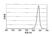
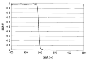
LED1,2としては、図10Aおよび図10Bに示す分光特性を有するものを使用し、ミラー6としては図11に示す反射率特性、ダイクロイックミラー4としては図12に示す透過率特性を有するものを使用し、光源射出光としては図13に示す分光特性を有する光を射出するようになっている。
本実施形態に係る内視鏡光源装置10の第1実施例について以下に説明する。
本実施例においては、図9に示されるように、2つのLED1,2を備えるとともに、各LED1,2とこれらに対応するコリメートレンズ11との間にそれぞれ絞り5を配置している。
LED1,2としては、図10Aおよび図10Bに示す分光特性を有するものを使用し、ミラー6としては図11に示す反射率特性、ダイクロイックミラー4としては図12に示す透過率特性を有するものを使用し、光源射出光としては図13に示す分光特性を有する光を射出するようになっている。
光路長が長い側の光路に配置された絞り5の開口径φ=34mm、距離L=12.55mm、近軸倍率絶対値β=0.94とし、内視鏡のライトガイドファイバの開口数NA=0.5とすることにより、φ/L=2.71、1.5NAβ/√(1-(NAβ)2)=1.02となり、条件式(6)を満足している。
また、光路長が短い側の光路に配置された絞り5の開口径φ=22mm、距離L=12.55mm、近軸倍率絶対値β=0.98とし、内視鏡のライトガイドファイバの開口数NA=0.5とすることにより、φ/L=1.75、1.5NAβ/√(1-(NAβ)2)=1.10となり、条件式(6)を満足している。
(第2実施例)
本実施形態に係る内視鏡光源装置10の第2実施例について以下に説明する。
本実施例においては、図14に示されるように、3つのLED1,2,3を備えるとともに、各LED1,2,3とこれらに対応するコリメートレンズ11との間にそれぞれ絞り5を配置している。
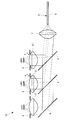
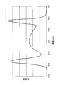
LED1,2,3としては、図15Aから図15Cに示す分光特性を有するものを使用し、ダイクロイックミラー6としては図16に示す反射率特性を有するものを使用し、ダイクロイックミラー4としては図17Aおよび図17Bに示す透過率特性を有するものを使用し、光源射出光としては図18に示す分光特性を有する光を射出するようになっている。
本実施形態に係る内視鏡光源装置10の第2実施例について以下に説明する。
本実施例においては、図14に示されるように、3つのLED1,2,3を備えるとともに、各LED1,2,3とこれらに対応するコリメートレンズ11との間にそれぞれ絞り5を配置している。
LED1,2,3としては、図15Aから図15Cに示す分光特性を有するものを使用し、ダイクロイックミラー6としては図16に示す反射率特性を有するものを使用し、ダイクロイックミラー4としては図17Aおよび図17Bに示す透過率特性を有するものを使用し、光源射出光としては図18に示す分光特性を有する光を射出するようになっている。
光路長が最も長い側の光路に配置された絞り5の開口径φ=34mm、距離L=12.55mm、近軸倍率絶対値β=0.91とし、内視鏡のライトガイドファイバの開口数NA=0.5とすることにより、φ/L=2.71、1.5NAβ/√(1-(NAβ)2)=0.98となり、条件式(6)を満足している。
光路長が2番目に長い側の光路に配置された絞り5の開口径φ=29mm、距離L=12.55mm、近軸倍率絶対値β=0.94とし、内視鏡のライトガイドファイバの開口数NA=0.5とすることにより、φ/L=2.31、1.5NAβ/√(1-(NAβ)2)=1.02となり、条件式(6)を満足している。
また、光路長が最も短い側の光路に配置された絞り5の開口径φ=21mm、距離L=12.55mm、近軸倍率絶対値β=0.94とし、内視鏡のライトガイドファイバの開口数NA=0.5とすることにより、φ/L=1.67、1.5NAβ/√(1-(NAβ)2)=1.10となり、条件式(6)を満足している。
(第3実施例)
本実施形態に係る内視鏡光源装置10の第3実施例について以下に説明する。
本実施例においては、図8に示されるように、3つのLED1,2,3を備えるとともに、各LED1,2,3とこれらに対応するコリメートレンズ11との間にそれぞれ絞り5を配置している。
各LED1,2,3の分光特性、ミラー6の反射率特性、各ダイクロイックミラー4の透過率特性および光源射出光の分光特性は第2実施例と同じである。
本実施形態に係る内視鏡光源装置10の第3実施例について以下に説明する。
本実施例においては、図8に示されるように、3つのLED1,2,3を備えるとともに、各LED1,2,3とこれらに対応するコリメートレンズ11との間にそれぞれ絞り5を配置している。
各LED1,2,3の分光特性、ミラー6の反射率特性、各ダイクロイックミラー4の透過率特性および光源射出光の分光特性は第2実施例と同じである。
光路長が最も長い側の光路に配置された絞り5の開口径φ=21mm、距離L=7.75mm、近軸倍率絶対値β=0.91とし、内視鏡のライトガイドファイバの開口数NA=0.5とすることにより、φ/L=2.71、1.5NAβ/√(1-(NAβ)2)=0.98となり、条件式(6)を満足している。
光路長が2番目に長い側の光路に配置された絞り5の開口径φ=21mm、距離L=9.09mm、近軸倍率絶対値β=0.94とし、内視鏡のライトガイドファイバの開口数NA=0.5とすることにより、φ/L=2.31、1.5NAβ/√(1-(NAβ)2)=1.02となり、条件式(6)を満足している。
また、光路長が最も短い側の光路に配置された絞り5の開口径φ=21mm、距離L=12.55mm、近軸倍率絶対値β=0.94とし、内視鏡のライトガイドファイバの開口数NA=0.5とすることにより、φ/L=1.67、1.5NAβ/√(1-(NAβ)2)=1.10となり、条件式(6)を満足している。
1,2,3 LED(固体光源)
4 ダイクロイックミラー(合波光学部材)
5 絞り(光量調節機構)
7 集光レンズ
8 ライトガイド
10 内視鏡光源装置
11 コリメートレンズ
L 距離
4 ダイクロイックミラー(合波光学部材)
5 絞り(光量調節機構)
7 集光レンズ
8 ライトガイド
10 内視鏡光源装置
11 コリメートレンズ
L 距離
Claims (5)
- 複数の固体光源と、
各該固体光源から射出された光をそれぞれ略平行光にする複数のコリメートレンズと、
各該コリメートレンズにより略平行光にされた光を合波する合波光学部材と、
少なくとも1つの前記固体光源と前記コリメートレンズとの間に配置され、各前記固体光源からの周辺光量を調節可能な光量調節機構と、
前記合波光学部材により合波された各前記固体光源からの光を集光して内視鏡のライトガイドの端面に入射させる集光レンズとを備える内視鏡光源装置。 - 前記光量調節機構が、各前記固体光源から前記集光レンズまでの光路長が短いほど多くの周辺光を遮光する請求項1に記載の内視鏡光源装置。
- 前記光量調節機構が、各前記固体光源と各前記コリメートレンズとの組合せ毎に、開口径が異なる絞りである請求項1または請求項2に記載の内視鏡光源装置。
- 前記光量調節機構が、各前記固体光源と各前記コリメートレンズとの組合せ毎に、各前記固体光源からの異なる距離に配置された絞りである請求項1または請求項2に記載の内視鏡光源装置。
- 前記絞りが以下の条件式を満足する請求項3または請求項4に記載の内視鏡光源装置。
φ/L≧1.5NAβ/√(1-(NAβ)2)
ここで、
φは前記絞りの開口径、
NAは前記ライトガイドの開口数、
βは前記固体光源が前記ライトガイドに結像する際の近軸倍率の絶対値、
Lは前記固体光源と前記絞りとの間の光路長
である。
Priority Applications (3)
| Application Number | Priority Date | Filing Date | Title |
|---|---|---|---|
| JP2018563735A JP6537751B2 (ja) | 2017-06-02 | 2018-04-09 | 内視鏡光源装置 |
| CN201880035843.1A CN110691545B (zh) | 2017-06-02 | 2018-04-09 | 内窥镜光源装置 |
| US16/693,339 US11051684B2 (en) | 2017-06-02 | 2019-11-24 | Endoscope light source device |
Applications Claiming Priority (2)
| Application Number | Priority Date | Filing Date | Title |
|---|---|---|---|
| JP2017-110067 | 2017-06-02 | ||
| JP2017110067 | 2017-06-02 |
Related Child Applications (1)
| Application Number | Title | Priority Date | Filing Date |
|---|---|---|---|
| US16/693,339 Continuation US11051684B2 (en) | 2017-06-02 | 2019-11-24 | Endoscope light source device |
Publications (1)
| Publication Number | Publication Date |
|---|---|
| WO2018221014A1 true WO2018221014A1 (ja) | 2018-12-06 |
Family
ID=64454667
Family Applications (1)
| Application Number | Title | Priority Date | Filing Date |
|---|---|---|---|
| PCT/JP2018/014847 Ceased WO2018221014A1 (ja) | 2017-06-02 | 2018-04-09 | 内視鏡光源装置 |
Country Status (4)
| Country | Link |
|---|---|
| US (1) | US11051684B2 (ja) |
| JP (1) | JP6537751B2 (ja) |
| CN (1) | CN110691545B (ja) |
| WO (1) | WO2018221014A1 (ja) |
Cited By (2)
| Publication number | Priority date | Publication date | Assignee | Title |
|---|---|---|---|---|
| US20210085170A1 (en) * | 2019-09-23 | 2021-03-25 | Nanosurgery Technology Corporation | Light engine for imaging system |
| US12096918B2 (en) | 2019-08-19 | 2024-09-24 | Nanosurgery Technology Corporation | Imaging needle system and apparatus with light engine |
Families Citing this family (2)
| Publication number | Priority date | Publication date | Assignee | Title |
|---|---|---|---|---|
| JP2022157309A (ja) * | 2021-03-31 | 2022-10-14 | 市光工業株式会社 | 車両用灯具 |
| CN116602606A (zh) * | 2023-05-31 | 2023-08-18 | 深圳市科曼医疗设备有限公司 | 内窥镜照明混光装置、照明系统和内窥镜 |
Citations (2)
| Publication number | Priority date | Publication date | Assignee | Title |
|---|---|---|---|---|
| JP2012014853A (ja) * | 2010-06-29 | 2012-01-19 | Nakakyu:Kk | Led照明装置 |
| JP2014161639A (ja) * | 2013-02-27 | 2014-09-08 | Fujifilm Corp | 光源装置、及びこれを用いた内視鏡システム |
Family Cites Families (12)
| Publication number | Priority date | Publication date | Assignee | Title |
|---|---|---|---|---|
| WO2001095317A1 (en) * | 2000-06-06 | 2001-12-13 | Matsushita Electric Industrial Co., Ltd. | Optical pickup device |
| JP2004101931A (ja) * | 2002-09-10 | 2004-04-02 | Konica Minolta Holdings Inc | 対物集光手段及び光ピックアップ装置 |
| JP2005342431A (ja) * | 2004-06-07 | 2005-12-15 | Pentax Corp | 光源装置 |
| JP4589670B2 (ja) | 2004-07-16 | 2010-12-01 | Hoya株式会社 | 内視鏡用光源装置 |
| JP4817632B2 (ja) | 2004-09-27 | 2011-11-16 | 京セラ株式会社 | Ledファイバ光源装置及びそれを用いた内視鏡 |
| JP2006184173A (ja) * | 2004-12-28 | 2006-07-13 | Fujinon Corp | 光透過率測定方法 |
| JP5259167B2 (ja) * | 2007-12-06 | 2013-08-07 | オリンパスメディカルシステムズ株式会社 | 光源装置および内視鏡装置 |
| EP2542145B1 (en) * | 2010-03-05 | 2020-08-12 | The General Hospital Corporation | Systems which provide microscopic images of at least one anatomical structure at a particular resolution |
| JP2011243440A (ja) * | 2010-05-19 | 2011-12-01 | Olympus Corp | 照明装置 |
| JP6128763B2 (ja) | 2012-06-25 | 2017-05-17 | オリンパス株式会社 | 光源装置 |
| EP3096176A4 (en) | 2014-01-15 | 2018-01-03 | Olympus Corporation | Endoscope device |
| JP6769605B2 (ja) * | 2016-08-16 | 2020-10-14 | 株式会社トーメーコーポレーション | レンズメータ |
-
2018
- 2018-04-09 CN CN201880035843.1A patent/CN110691545B/zh active Active
- 2018-04-09 WO PCT/JP2018/014847 patent/WO2018221014A1/ja not_active Ceased
- 2018-04-09 JP JP2018563735A patent/JP6537751B2/ja active Active
-
2019
- 2019-11-24 US US16/693,339 patent/US11051684B2/en active Active
Patent Citations (2)
| Publication number | Priority date | Publication date | Assignee | Title |
|---|---|---|---|---|
| JP2012014853A (ja) * | 2010-06-29 | 2012-01-19 | Nakakyu:Kk | Led照明装置 |
| JP2014161639A (ja) * | 2013-02-27 | 2014-09-08 | Fujifilm Corp | 光源装置、及びこれを用いた内視鏡システム |
Cited By (2)
| Publication number | Priority date | Publication date | Assignee | Title |
|---|---|---|---|---|
| US12096918B2 (en) | 2019-08-19 | 2024-09-24 | Nanosurgery Technology Corporation | Imaging needle system and apparatus with light engine |
| US20210085170A1 (en) * | 2019-09-23 | 2021-03-25 | Nanosurgery Technology Corporation | Light engine for imaging system |
Also Published As
| Publication number | Publication date |
|---|---|
| JP6537751B2 (ja) | 2019-07-03 |
| JPWO2018221014A1 (ja) | 2019-06-27 |
| CN110691545A (zh) | 2020-01-14 |
| US20200093359A1 (en) | 2020-03-26 |
| CN110691545B (zh) | 2021-06-18 |
| US11051684B2 (en) | 2021-07-06 |
Similar Documents
| Publication | Publication Date | Title |
|---|---|---|
| JP6537751B2 (ja) | 内視鏡光源装置 | |
| JP6270407B2 (ja) | 光源装置および投射型表示装置 | |
| KR101616635B1 (ko) | 레이저 합성 광학 장치 | |
| WO2007079398A3 (en) | System and method for fiber optic bundle-based illumination for imaging system | |
| US8837043B2 (en) | Light source arrangement for an illumination device of a medical-optical observation apparatus | |
| US9482870B2 (en) | Light source apparatus | |
| JP2015223462A5 (ja) | ||
| JP2015223463A5 (ja) | ||
| JP2015138712A5 (ja) | ||
| JP2007121590A (ja) | 共焦点スキャナ | |
| US11567272B2 (en) | Optical coupling device | |
| WO2015111540A1 (ja) | 内視鏡用光源システム | |
| JP2019004061A (ja) | 発光装置 | |
| JP6203467B1 (ja) | 光源装置 | |
| US11262573B2 (en) | Endoscope light-source device | |
| US11177635B2 (en) | Light source device | |
| US20060203507A1 (en) | Illumination device | |
| JP6306942B2 (ja) | 集光光学系及び光源光学系 | |
| KR20170026942A (ko) | 조명 광학 시스템 | |
| JP2018183251A (ja) | 内視鏡用照明光学系 |
Legal Events
| Date | Code | Title | Description |
|---|---|---|---|
| ENP | Entry into the national phase |
Ref document number: 2018563735 Country of ref document: JP Kind code of ref document: A |
|
| 121 | Ep: the epo has been informed by wipo that ep was designated in this application |
Ref document number: 18809551 Country of ref document: EP Kind code of ref document: A1 |
|
| NENP | Non-entry into the national phase |
Ref country code: DE |
|
| 122 | Ep: pct application non-entry in european phase |
Ref document number: 18809551 Country of ref document: EP Kind code of ref document: A1 |