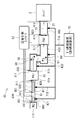
WO2018220738A1 - レーザ装置、及びeuv光生成システム - Google Patents
レーザ装置、及びeuv光生成システム Download PDFInfo
- Publication number
- WO2018220738A1 WO2018220738A1 PCT/JP2017/020223 JP2017020223W WO2018220738A1 WO 2018220738 A1 WO2018220738 A1 WO 2018220738A1 JP 2017020223 W JP2017020223 W JP 2017020223W WO 2018220738 A1 WO2018220738 A1 WO 2018220738A1
- Authority
- WO
- WIPO (PCT)
- Prior art keywords
- temperature
- laser
- laser device
- block
- enclosure
- Prior art date
- Legal status (The legal status is an assumption and is not a legal conclusion. Google has not performed a legal analysis and makes no representation as to the accuracy of the status listed.)
- Ceased
Links
Images







Classifications
-
- H—ELECTRICITY
- H01—ELECTRIC ELEMENTS
- H01S—DEVICES USING THE PROCESS OF LIGHT AMPLIFICATION BY STIMULATED EMISSION OF RADIATION [LASER] TO AMPLIFY OR GENERATE LIGHT; DEVICES USING STIMULATED EMISSION OF ELECTROMAGNETIC RADIATION IN WAVE RANGES OTHER THAN OPTICAL
- H01S3/00—Lasers, i.e. devices using stimulated emission of electromagnetic radiation in the infrared, visible or ultraviolet wave range
- H01S3/02—Constructional details
- H01S3/04—Arrangements for thermal management
- H01S3/0404—Air- or gas cooling, e.g. by dry nitrogen
-
- H—ELECTRICITY
- H01—ELECTRIC ELEMENTS
- H01S—DEVICES USING THE PROCESS OF LIGHT AMPLIFICATION BY STIMULATED EMISSION OF RADIATION [LASER] TO AMPLIFY OR GENERATE LIGHT; DEVICES USING STIMULATED EMISSION OF ELECTROMAGNETIC RADIATION IN WAVE RANGES OTHER THAN OPTICAL
- H01S3/00—Lasers, i.e. devices using stimulated emission of electromagnetic radiation in the infrared, visible or ultraviolet wave range
- H01S3/0014—Monitoring arrangements not otherwise provided for
-
- H—ELECTRICITY
- H01—ELECTRIC ELEMENTS
- H01S—DEVICES USING THE PROCESS OF LIGHT AMPLIFICATION BY STIMULATED EMISSION OF RADIATION [LASER] TO AMPLIFY OR GENERATE LIGHT; DEVICES USING STIMULATED EMISSION OF ELECTROMAGNETIC RADIATION IN WAVE RANGES OTHER THAN OPTICAL
- H01S3/00—Lasers, i.e. devices using stimulated emission of electromagnetic radiation in the infrared, visible or ultraviolet wave range
- H01S3/005—Optical devices external to the laser cavity, specially adapted for lasers, e.g. for homogenisation of the beam or for manipulating laser pulses, e.g. pulse shaping
-
- H—ELECTRICITY
- H01—ELECTRIC ELEMENTS
- H01S—DEVICES USING THE PROCESS OF LIGHT AMPLIFICATION BY STIMULATED EMISSION OF RADIATION [LASER] TO AMPLIFY OR GENERATE LIGHT; DEVICES USING STIMULATED EMISSION OF ELECTROMAGNETIC RADIATION IN WAVE RANGES OTHER THAN OPTICAL
- H01S3/00—Lasers, i.e. devices using stimulated emission of electromagnetic radiation in the infrared, visible or ultraviolet wave range
- H01S3/02—Constructional details
-
- H—ELECTRICITY
- H01—ELECTRIC ELEMENTS
- H01S—DEVICES USING THE PROCESS OF LIGHT AMPLIFICATION BY STIMULATED EMISSION OF RADIATION [LASER] TO AMPLIFY OR GENERATE LIGHT; DEVICES USING STIMULATED EMISSION OF ELECTROMAGNETIC RADIATION IN WAVE RANGES OTHER THAN OPTICAL
- H01S3/00—Lasers, i.e. devices using stimulated emission of electromagnetic radiation in the infrared, visible or ultraviolet wave range
- H01S3/23—Arrangements of two or more lasers not provided for in groups H01S3/02 - H01S3/22, e.g. tandem arrangements of separate active media
- H01S3/2308—Amplifier arrangements, e.g. MOPA
- H01S3/2316—Cascaded amplifiers
-
- H—ELECTRICITY
- H05—ELECTRIC TECHNIQUES NOT OTHERWISE PROVIDED FOR
- H05G—X-RAY TECHNIQUE
- H05G2/00—Apparatus or processes specially adapted for producing X-rays, not involving X-ray tubes, e.g. involving generation of a plasma
- H05G2/001—Production of X-ray radiation generated from plasma
- H05G2/008—Production of X-ray radiation generated from plasma involving an energy-carrying beam in the process of plasma generation
- H05G2/0082—Production of X-ray radiation generated from plasma involving an energy-carrying beam in the process of plasma generation the energy-carrying beam being a laser beam
-
- H—ELECTRICITY
- H01—ELECTRIC ELEMENTS
- H01S—DEVICES USING THE PROCESS OF LIGHT AMPLIFICATION BY STIMULATED EMISSION OF RADIATION [LASER] TO AMPLIFY OR GENERATE LIGHT; DEVICES USING STIMULATED EMISSION OF ELECTROMAGNETIC RADIATION IN WAVE RANGES OTHER THAN OPTICAL
- H01S3/00—Lasers, i.e. devices using stimulated emission of electromagnetic radiation in the infrared, visible or ultraviolet wave range
- H01S3/02—Constructional details
- H01S3/025—Constructional details of solid state lasers, e.g. housings or mountings
- H01S3/027—Constructional details of solid state lasers, e.g. housings or mountings comprising a special atmosphere inside the housing
Definitions
- the present disclosure relates to a laser apparatus and an EUV light generation system.
- an LPP (Laser Produced) Plasma) type device using plasma generated by irradiating a target material with laser light, and a DPP (Discharge Produced Plasma) using plasma generated by discharge are used.
- Three types of devices have been proposed: a device of the type and an SR (Synchrotron-Radiation) type device using orbital radiation.
- a first laser device of the present disclosure includes an optical element disposed on a laser optical path, and a first temperature sensor that measures a first temperature of a gas at a position away from the optical element, A plurality of surrounding blocks covering a part, an outer body including a plurality of surrounding blocks and configured to cover the laser optical path, and connected to each first temperature sensor; A control unit that identifies the surrounding block in which the rise in temperature is measured as the surrounding block in which an abnormality has occurred.
- a second laser device of the present disclosure includes an optical element disposed on a laser optical path, an optical path tube that covers the optical element, an intake unit that introduces purge gas therein, and an exhaust unit that exhausts purge gas from inside
- a plurality of optical path tubes including a first temperature sensor for measuring a first temperature of the purge gas exhausted from the exhaust unit, and an envelope configured to cover the laser optical path with the plurality of optical path tubes, And a control unit that identifies an optical path tube in which an increase in the first temperature is measured in the envelope as an optical path tube in which an abnormality has occurred.
- a first EUV light generation system of the present disclosure includes an EUV chamber in which EUV light is generated, and a laser device that emits laser light toward the EUV chamber, and the laser device is an optical element disposed on a laser light path.
- An element and a first temperature sensor that measures a first temperature of a gas at a position remote from the optical element, and includes a plurality of surrounding blocks that cover a part of the laser optical path, and a plurality of surrounding blocks An abnormality has occurred in the enclosure that is configured to cover the laser light path and the enclosure block that is connected to each first temperature sensor and in which the first temperature rise is measured.
- a second EUV light generation system of the present disclosure includes an EUV chamber in which EUV light is generated, and a laser device that emits laser light toward the EUV chamber, and the laser device is an optical element disposed on the laser light path.
- An optical path tube covering the element, the optical element, an intake part for introducing purge gas therein, an exhaust part for exhausting purge gas from the inside, and a first temperature for measuring a first temperature of the purge gas exhausted from the exhaust part
- a plurality of optical path tubes including a plurality of temperature sensors, an envelope configured to cover the laser optical path with the plurality of optical path tubes, and each of the first temperature sensors connected to the first temperature sensor.
- a control unit that identifies the optical path tube in which the rise of the optical path is measured as an optical path tube in which an abnormality has occurred.
- FIG. 1 schematically illustrates an exemplary configuration of an exemplary LPP type EUV light generation system.
- FIG. 2 schematically shows a configuration example of an EUV light generation system according to a comparative example.
- FIG. 3 schematically shows a configuration example of a main part of a laser apparatus in an EUV light generation system according to a comparative example.
- FIG. 4 schematically illustrates a configuration example of a main part of the laser apparatus according to the first embodiment.
- FIG. 5 schematically shows a flowchart of a first example of the abnormal heating detection operation in the laser apparatus according to the first embodiment.
- FIG. 6 schematically shows a flowchart of a second example of the abnormal heating detection operation in the laser apparatus according to the first embodiment.
- FIG. 7 schematically illustrates a configuration example of a main part of a laser device according to a modification of the first embodiment.
- FIG. 8 schematically illustrates a first example of a flowchart of an abnormal heating detection operation in the laser apparatus according to the second embodiment.
- FIG. 9 schematically illustrates a configuration example of a main part of the laser device according to the third embodiment.
- FIG. 10 schematically shows a flowchart of a first example of the abnormal heating detection operation in the laser apparatus according to the third embodiment.
- FIG. 11 schematically shows a flowchart of a second example of the abnormal heating detection operation in the laser apparatus according to the third embodiment.
- FIG. 12 schematically illustrates a configuration example of a main part of the laser device according to the fourth embodiment.
- FIG. 13 schematically illustrates a configuration example of a main part of a laser device according to the fifth embodiment.
- Second Embodiment> (Laser apparatus having a function of measuring the temperature of purge gas supplied from a gas supply apparatus) (FIG. 8) 4.1 Configuration 4.2 Operation 4.3 Action / Effect ⁇ 5.
- Third Embodiment> (Laser apparatus having a function of measuring the intake temperature of purge gas) (FIGS. 9 to 11) 5.1 Configuration 5.2 Operation 5.3 Action / Effect ⁇ 6.
- Embodiment 4> (Laser apparatus having a function of measuring the exhaust temperature of purge gas in the gap of the optical path tube) (FIG. 12) 6.1 Configuration 6.2 Operation 6.3 Action / Effect ⁇ 7.
- Embodiment 5> (Laser apparatus having a function of measuring the temperature of the purge gas inside the optical path tube) (FIG. 13) 7.1 Configuration 7.2 Operation, Action, and Effect ⁇ 8.
- FIG. 1 schematically shows a configuration of an exemplary LPP type EUV light generation system.
- the EUV light generation apparatus 1 may be used with at least one laser apparatus 3.
- a system including the EUV light generation apparatus 1 and the laser apparatus 3 is referred to as an EUV light generation system 11.
- the EUV light generation apparatus 1 includes a chamber 2 and a target supply unit 26.
- the chamber 2 is a container that can be sealed.
- the target supply unit 26 is configured to supply the target material to the inside of the chamber 2 and is attached so as to penetrate the wall of the chamber 2, for example.
- the material of the target substance may include, but is not limited to, tin, terbium, gadolinium, lithium, xenon, or a combination of any two or more thereof.
- the wall of the chamber 2 is provided with at least one through hole.
- the through hole is closed by the window 21, and the pulse laser beam 32 output from the laser device 3 is transmitted through the window 21.
- an EUV collector mirror 23 having a spheroidal reflecting surface is disposed.
- the EUV collector mirror 23 has first and second focal points.
- the EUV collector mirror 23 may be arranged such that its first focal point is located in the plasma generation region 25 and its second focal point is located in the intermediate focal point (IF) 292.
- a through hole 24 is provided at the center of the EUV collector mirror 23, and the pulse laser beam 33 passes through the through hole 24.
- the EUV light generation apparatus 1 includes an EUV light generation controller 5, a target sensor 4, and the like.
- the target sensor 4 is configured to detect one or more of the presence, trajectory, position, and speed of the target 27.
- the target sensor 4 may have an imaging function.
- the EUV light generation apparatus 1 includes a connection portion 29 that allows communication between the inside of the chamber 2 and the inside of the exposure apparatus 6.
- a wall 291 in which an aperture 293 is formed is provided inside the connection portion 29. The wall 291 is arranged such that its aperture 293 is located at the second focal position of the EUV collector mirror 23.
- the EUV light generation apparatus 1 includes a laser beam transmission device 34, a laser beam focusing mirror 22, a target recovery unit 28 for recovering the target 27, and the like.
- the laser light transmission device 34 includes an optical element for defining the transmission state of the laser light and an actuator for adjusting the position, posture, and the like of the optical element.
- the pulsed laser beam 31 output from the laser device 3 passes through the window 21 as the pulsed laser beam 32 through the laser beam transmission device 34 and enters the chamber 2.
- the pulsed laser light 32 travels in the chamber 2 along at least one laser light path, is reflected by the laser light focusing mirror 22, and is irradiated onto at least one target 27 as pulsed laser light 33.
- the target supply unit 26 is configured to output a target 27 formed of the target material toward the plasma generation region 25 inside the chamber 2.
- the target 27 is irradiated with at least one pulse included in the pulse laser beam 33.
- the target 27 irradiated with the pulse laser beam is turned into plasma, and radiation light 251 is emitted from the plasma.
- the EUV light 252 included in the radiation light 251 is selectively reflected by the EUV collector mirror 23.
- the EUV light 252 reflected by the EUV collector mirror 23 is collected at the intermediate condensing point 292 and output to the exposure apparatus 6.
- a single target 27 may be irradiated with a plurality of pulses included in the pulse laser beam 33.
- the EUV light generation controller 5 is configured to control the entire EUV light generation system 11.
- the EUV light generation controller 5 is configured to process the detection result of the target sensor 4. Based on the detection result of the target sensor 4, the EUV light generation controller 5 may be configured to control, for example, the timing at which the target 27 is output, the output direction of the target 27, and the like. Further, the EUV light generation controller 5 may be configured to control, for example, the oscillation timing of the laser device 3, the traveling direction of the pulse laser light 32, the focusing position of the pulse laser light 33, and the like.
- the various controls described above are merely examples, and other controls may be added as necessary.
- FIG. 2 schematically shows a configuration example of the EUV light generation system 11A according to the comparative example.
- substantially the same components as those of the EUV light generation system 11 shown in FIG. 1 are denoted by the same reference numerals, and description thereof will be omitted as appropriate.
- the EUV light generation system 11A may include a chamber 2, a laser device 3, a laser light transmission device 34, and an EUV light generation controller 5.
- the laser device 3 includes a master oscillator (MO) 110, an optical isolator 81, a high reflection mirror 82, a plurality of amplifiers PA1, PA2, PA3, PA4, a plurality of PA power supplies 121, 122, 123, 124, a laser
- the control part 51 may be included.
- the laser control unit 51 is connected to the EUV light generation controller 5.
- the laser device 3 may further include a plurality of optical elements provided on the laser optical path.
- the plurality of optical elements provided on the laser optical path may include an optical element (not shown) in addition to the optical isolator 81 and the high reflection mirror 82.
- the plurality of optical elements may be configured to perform at least one of laser beam transmission and laser beam shaping.
- the master oscillator 110 and the amplifiers PA1, PA2, PA3, and PA4 may constitute a MOPA (Master Oscillator Power Amplifier).
- MOPA Master Oscillator Power Amplifier
- Each of the amplifiers PA1, PA2, PA3, and PA4 may be disposed on a laser beam path that is output from the master oscillator 110 via the optical isolator 81 and the high reflection mirror 82.
- the amplifiers PA1, PA2, PA3, and PA4 may be connected to PA power sources 121, 122, 123, and 124, respectively.
- Each of amplifiers PA1, PA2, PA3, and PA4 may include a laser chamber 60 that amplifies laser light, an input window 61a that receives laser light, and an output window 61b that outputs laser light.
- the laser chamber 60 may include an internal electrode for discharge.
- the PA power supplies 121, 122, 123, and 124 are connected to the laser control unit 51, respectively.
- the optical isolator 81 may be disposed on the laser optical path from the master oscillator 110 to the amplifier PA1.
- the optical isolator 81 may be configured to open and close in accordance with instructions from the laser control unit 51 and to transmit and block laser light.
- the laser beam transmission device 34 includes a transmission optical system arranged in a path between the laser device 3 and the chamber 2.
- the transmission optical system may include a plurality of high reflection mirrors 91 and 92 and a beam adjusting device 90.
- the chamber 2 includes a target sensor 4, a window 21, an EUV light condensing mirror 23, a target supply unit 26, a target recovery unit 28, a laser condensing optical system 94, a mirror holding member 95, and a damper mirror 130. And a beam dump device 131 may be included.
- the beam adjusting device 90 may be disposed on a laser light path from the laser light transmission device 34 to the laser focusing optical system 94.
- the beam adjusting device 90 may be configured to adjust the divergence angle of the laser light according to an instruction of the divergence angle control signal S5 from the laser control unit 51.
- the laser light path from the master oscillator 110 to the chamber 2 may be almost entirely covered with a plurality of light path tubes 400.
- the optical path tube 400 may be configured to cover a part or the whole of the optical elements constituting the laser optical path.
- the optical path tube 400 may be connected to the gas supply device 70 via the gas supply path 71.
- the gas supply device 70 may supply purge gas into the optical path tube 400 via the gas supply path 71.
- the laser condensing optical system 94 may be configured to condense the pulsed laser light 33 incident on the chamber 2 onto the plasma generation region 25.
- the laser focusing optical system 94 may include a laser focusing mirror 22 and a convex mirror 93.
- the mirror holding member 95 may be fixed to the chamber 2 and hold the EUV collector mirror 23 and the laser focusing optical system 94.
- the EUV collector mirror 23 may be held via a suitable holder.
- the damper mirror 130 may be arranged on the laser light path downstream of the plasma generation region 25 and may be configured to reflect the pulsed laser light 33 that has passed through the plasma generation region 25 toward the beam dump device 131.
- the beam dump device 131 may be disposed at a position where the pulse laser beam 33 reflected by the damper mirror 130 enters.
- the pulse laser beam 33 may be incident on a beam dump device 131 disposed on the chamber wall.
- the beam dump device 131 may be connected to the cooling device 132.
- the EUV light generation system 11A may output the EUV light 252 based on the EUV light output command signal S1 from the exposure apparatus controller 6a of the exposure apparatus 6.
- the EUV light generation controller 5 may transmit the target output signal S3 to the target supply unit 26 and output the target 27 based on the EUV light output command signal S1.
- the target sensor 4 may detect the target 27 and output the target detection signal S2 to the EUV light generation controller 5.
- the EUV light generation controller 5 may output a light emission trigger signal S4 generated by adding a predetermined delay time to the target detection signal S2 to the laser control unit 51 of the laser device 3.
- the laser control unit 51 can output a laser output signal to the master oscillator 110 when the light emission trigger signal S4 is input. Prior to this, the laser controller 51 may turn on the PA power supplies 121, 122, 123, and 124. As a result, the PA power supplies 121, 122, 123, and 124 can supply voltages or currents to the internal electrodes of the amplifiers PA1, PA2, PA3, and PA4, and amplify the amplifiers PA1, PA2, PA3, and PA4. It is good.
- the master oscillator 110 can output pulsed laser light in synchronization with the laser output signal from the laser control unit 51.
- the laser control unit 51 may open the optical isolator 81.
- the pulsed laser light output from the master oscillator 110 can be amplified by the amplifiers PA1, PA2, PA3, and PA4 and can enter the beam adjusting device 90 via the laser light transmission device 34.
- the beam adjusting device 90 may adjust and output the divergence angle of the incident pulse laser beam.
- the pulse laser beam output from the beam adjusting device 90 can be input to the chamber 2 after passing through the window 21.
- the pulse laser beam output from the laser device 3 reaches several kW to several tens kW.
- the pulse laser beam input to the chamber 2 is focused and irradiated on the target 27 that has reached the plasma generation region 25 by the laser focusing optical system 94. Thereby, the radiation light 251 including the EUV light 252 can be obtained.
- the irradiation diameter of the pulse laser beam may be larger than the diameter of the target 27.
- a part of the pulse laser beam 33 may be incident on the damper mirror 130 without being irradiated on the target 27.
- the pulse laser beam 33 reflected by the damper mirror 130 is absorbed by the beam dump device 131 and converted into heat.
- the heat generated at this time is discharged to the outside by the cooling device 132.
- FIG. 3 schematically shows a configuration example of a main part of the laser apparatus 3 in the EUV light generation system 11A according to the comparative example.
- the laser light transmission device 34 is not shown for ease of explanation.
- FIG. 3 only two amplifiers PA1 and PA2 are illustrated, but three or more amplifiers may be provided.
- an optical isolator 81 On the laser light path from the master oscillator 110 to the window 21 of the chamber 2, an optical isolator 81, an amplifier PA1, high reflection mirrors 96 and 97, and an amplifier PA2 may be sequentially arranged.
- the high reflection mirror 96 is held by a holder 98.
- the high reflection mirror 97 is held by a holder 99.
- the laser light path from the master oscillator 110 to the chamber 2 is almost entirely covered by a plurality of light path tubes 400.
- the optical path tube 400 may cover a plurality of optical elements constituting the laser optical path, such as the optical isolator 81 and the high reflection mirrors 96 and 97.
- the optical path tube 400 may be divided into a plurality of blocks.
- the optical path tube 400 includes an exhaust hole communicating with the outside.
- the exhaust hole may be formed by a gap 401 at a connection portion between each block of the optical path tube 400 and each of the amplifiers PA1 and PA2 and the chamber 2.
- the exhaust holes may be provided in some blocks instead of all the blocks of the optical path tube 400.
- one end of the connection portion between each block of the optical path tube 400 and each of the amplifiers PA1, PA2 and the chamber 2 may be closed by a window.
- the gas supply device 70 supplies purge gas to the inside of the optical path tube 400 through the main supply path 71A and a plurality of branch supply paths 71B branched from the main supply path 71A.
- Each block of the optical path tube 400 is connected to a pipe constituting the branch supply path 71B.
- the laser device 3 may further include a temperature sensor 410 and a temperature measurement controller 52.
- the temperature sensor 410 may be provided on, for example, an optical element such as a lens or a mirror disposed on the laser light path, or a holding member that holds the optical element.
- the optical elements arranged on the laser optical path may be, for example, the optical isolator 81, the input windows 61a and output windows 61b of the amplifiers PA1 and PA2, the high reflection mirrors 96 and 97, the window 21 of the chamber 2, and the like.
- the holding member that holds the optical element may be, for example, holders 98 and 99 that hold the high reflection mirrors 96 and 97.
- the temperature measurement controller 52 may detect abnormal heating of the optical element and the holding member based on the temperature measurement result by the temperature sensor 410.
- the gas supply device 70 supplies purge gas into the optical path tube 400 through the main supply path 71A and the plurality of branch supply paths 71B.
- the gas supply device 70 may be a CDA supply device that supplies CDA (dry air, compressed dry air) as the purge gas.
- the CDA may be dry air controlled at a dew point temperature of ⁇ 70 ° C. or lower.
- the flow rate of the purge gas supplied by the gas supply device 70 may be set such that the purge gas is replaced every 10 minutes for each block of the optical path tube 400, for example. For example, when supplying CDA as the purge gas, the flow rate may be 200 L to 300 L / min.
- the purge gas supplied from the gas supply device 70 flows through the laser beam path and is exhausted to the outside through the exhaust hole.
- the purpose of flowing the purge gas may be to flow clean purge gas through the laser beam path to suppress deterioration of the optical elements constituting the laser beam path due to condensation or moisture absorption.
- the temperature measurement controller 52 may be connected to the EUV light generation controller 5 and transmit a signal indicating that abnormal heating has been detected to the EUV light generation controller 5.
- the EUV light generation controller 5 may stop the laser device 3 by displaying an alarm on a display (not shown).
- the laser device 3 according to the comparative example is inferior in terms of measurement accuracy and diagnostic accuracy.
- the laser device 3 it is the surfaces of the optical element and the holding member that generate heat when there is an abnormality. If it is a holding member, the surface measurement is easy, but in the optical element, the surface is a laser reflecting surface, and it is almost impossible to install a measuring instrument or the like on this surface. Therefore, although the side surface and the back surface of the optical element are measured, since it takes time until the heat generation on the surface is reflected on the side surface and the back surface, the measurement accuracy and the diagnostic accuracy can be lowered.
- Embodiment 1> Laser apparatus having a function of measuring the exhaust temperature of purge gas
- the laser apparatus and the EUV light generation system according to the first embodiment of the present disclosure will be described.
- substantially the same components as those of the laser device 3 and the EUV light generation system 11A according to the comparative example are denoted by the same reference numerals, and description thereof is omitted as appropriate.
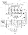
- FIG. 4 schematically shows a configuration example of a main part of the laser device 3A according to the first embodiment.
- the EUV light generation system according to Embodiment 1 may be configured to include a laser device 3A instead of the laser device 3 in the EUV light generation system 11A according to the comparative example.
- the laser device 3A includes a temperature sensor 411 as a first temperature sensor instead of the temperature sensor 410 in the laser device 3 according to the comparative example.
- the temperature sensor 411 may be a thermocouple.
- the laser apparatus 3A includes an enclosure provided so as to surround a laser optical path from the master oscillator 110 to the chamber 2.
- the envelope may be constituted by a plurality of optical path tubes 400.
- the envelope includes a plurality of envelope blocks 420 provided along the laser optical path.
- Each enclosure block 420 may be configured to cover a part of the laser light path from the master oscillator 110 to the chamber 2.
- the envelope may be configured to cover the laser beam path from the master oscillator 110 to the chamber 2 by arranging a plurality of envelope blocks 420.
- Each of the plurality of surrounding blocks 420 is provided with at least one optical element such as the optical isolator 81 and the high reflection mirrors 96 and 97.
- a gap 401 may be formed at the connection portion between each outer block 420 of the optical path tube 400 and each of the amplifiers PA1 and PA2 and the chamber 2 as in the laser device 3 according to the comparative example. In the configuration example of FIG. 4, an example in which the gap 401 is not formed is shown.
- the optical path tube 400 includes an intake port 421 as an intake portion and an exhaust port 422 as an exhaust portion. At least one intake port 421 is provided for each enclosure block 420. The intake port 421 is connected to the branch supply path 71B for each outer block 420, and introduces the purge gas from the gas supply device 70 into the optical path pipe 400 through the main supply path 71A and the branch supply path 71B. At least one exhaust port 422 is provided for each enclosure block 420, and the purge gas is exhausted from the inside of the optical path tube 400 for each enclosure block 420.
- At least one temperature sensor 411 is provided for each enclosure block 420 and is spaced from the optical elements such as the optical isolator 81 and the high reflection mirrors 96 and 97 and the holders 98 and 99.
- the temperature sensor 411 may be a first temperature sensor that measures a first temperature of a gas at a position away from the optical element. Further, the temperature sensor 411 measures the first temperature of the gas at a position away from the holders 98 and 99 holding the high reflection mirrors 96 and 97.
- the gas here may include a purge gas.
- the temperature sensor 411 measures the first temperature of the atmosphere in each enclosure block 420 by measuring the exhaust temperature of the purge gas exhausted from the exhaust port 422 for each enclosure block 420. To do.
- the temperature measurement controller 52 is connected to each temperature sensor 411, and based on the measurement result by each temperature sensor 411, the outside block 420 in which an increase in the exhaust gas temperature is measured in the enclosure is outside A control unit identified as the surrounding block 420 may be used. Further, the temperature measurement controller 52 is connected to each temperature sensor 411, and an abnormality has occurred in the optical path tube 400 in which the rise in the exhaust temperature is measured in the envelope based on the measurement result by each temperature sensor 411. The control part specified as the optical path tube 400 may be sufficient.
- the temperature measurement controller 52 identifies the surrounding block 420 in which an abnormality has occurred. Also in the embodiment described later, a case where the surrounding block 420 in which an abnormality has occurred is specified will be described as an example.
- the gas supply device 70 supplies the purge gas to the inside of each outer block 420 of the optical path tube 400 through the main supply path 71A and the plurality of branch supply paths 71B connected to the intake port 421.
- the purge gas supplied from the gas supply device 70 flows through the laser optical path for each outer block 420 and is exhausted from the exhaust port 422 to the outside of the optical path tube 400.
- optical elements such as the optical isolator 81 and the high reflection mirrors 96 and 97 are damaged, or when an apparatus abnormality such as laser optical axis misalignment occurs, the optical element itself or the holding member of the optical element is heated and the temperature rises. Arise. At that time, since the gas temperature also rises, abnormal heating can be detected by measuring the exhaust temperature of the purge gas exhausted from the exhaust port 422 by the temperature sensor 411.
- the exhaust temperature as the first temperature is measured by the temperature sensor 411 for each enclosure block 420.
- the temperature measurement controller 52 generates abnormal heating in the enclosure block 420 provided with the temperature sensor 411 in which the exhaust temperature is measured to be equal to or higher than a predetermined threshold among the plurality of enclosure blocks 420 in the enclosure. Judge that you are doing.
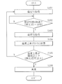
- FIG. 5 schematically shows a flowchart of a first example of the abnormal heating detection operation in the laser apparatus 3A.
- the temperature measurement controller 52 performs the following abnormal heating detection operation for each enclosure block 420. Thereby, the enclosure block 420 in which abnormal heating has occurred is identified among the plurality of enclosure blocks 420 in the enclosure.
- the temperature measurement controller 52 acquires the exhaust temperature T1 by the temperature sensor 411 (step S101).
- the temperature measurement controller 52 determines whether or not the set time t has elapsed (step S102).
- the set time t may be, for example, 1 second or more and 10 seconds or less. If the temperature measurement controller 52 determines that the set time t has not elapsed (step S102; N), the determination of step S102 is repeated until the set time t has elapsed.
- the temperature sensor 411 acquires the exhaust temperature T2 after the set time t has elapsed (step S103).
- the temperature measurement controller 52 calculates the temperature difference (T2 ⁇ T1) between the exhaust temperature T2 after the set time t has elapsed and the exhaust temperature T1 before the set time t has elapsed, so that the temperature after the set time t has elapsed.
- the increase is calculated (step S104).
- the temperature measurement controller 52 determines whether or not the temperature rise is equal to or greater than a predetermined threshold (step S105).
- the predetermined threshold may be 3 ° C., for example.
- the predetermined threshold value may be changed according to the flow rate of the purge gas supplied from the gas supply device 70. If the temperature measurement controller 52 determines that the temperature rise is not equal to or greater than the predetermined threshold (step S105; N), the process returns to step S101.
- step S105 when it is determined that the temperature rise is equal to or greater than the predetermined threshold (step S105; Y), the temperature measurement controller 52 indicates that abnormal heating has occurred in the surrounding block 420 where the temperature rise is measured. Judgment is made (step S106), and the abnormal heating detection operation process is terminated.
- the temperature measurement controller 52 may calculate the rate of change of the exhaust temperature as the first temperature measured by the temperature sensor 411 for each of the surrounding blocks 420, for example. Then, the temperature measurement controller 52 is provided in the outer block 420 provided with the temperature sensor 411 in which the temperature change rate is measured out of a plurality of the outer blocks 420 in the outer envelope. It may be determined that abnormal heating has occurred.
- FIG. 6 schematically shows a flowchart of a second example of the abnormal heating detection operation in the laser apparatus 3A.
- the temperature measurement controller 52 performs the following abnormal heating detection operation for each enclosure block 420. Thereby, the enclosure block 420 in which abnormal heating has occurred is identified among the plurality of enclosure blocks 420 in the enclosure.
- the temperature measurement controller 52 performs the same operation as steps S101 to S104 in FIG. 5, and then calculates the temperature increase gradient (T2-T1) / t after the set time t has elapsed (step S111). .
- the rate of change in temperature after the set time t has elapsed is calculated.
- the temperature measurement controller 52 determines whether or not the temperature increase gradient is equal to or greater than a predetermined threshold (step S112).
- the predetermined threshold may be, for example, 0.5 ° C./second.
- the predetermined threshold value may be changed according to the flow rate of the purge gas supplied from the gas supply device 70.
- step S112 when it is determined that the temperature increase gradient is equal to or greater than the predetermined threshold (step S112; Y), the temperature measurement controller 52 generates abnormal heating in the surrounding block 420 where the temperature increase gradient is measured. It judges that it has carried out (step S113), and complete
- the temperature measurement controller 52 transmits a signal indicating that abnormal heating has been detected to the EUV light generation controller 5. May be.
- the EUV light generation controller 5 may stop the emission trigger signal S4 to the laser device 3A and stop the operation of the laser device 3A. Further, the EUV light generation controller 5 may display information on the surrounding block 420 in which the abnormality is specified on a display (not shown). Thus, the operator may check for damage to the optical element in the surrounding block 420 in which the abnormality is specified. When the optical element is damaged, the operator may replace the damaged optical element.
- the exhaust temperature is measured at the exhaust port 422 for each of the surrounding blocks 420, and the surrounding block 420 in which abnormal heating occurs is specified based on the measurement result.
- the number of measurement points can be reduced.
- the whole apparatus structure can be simplified.
- the laser device 3 ⁇ / b> A of the first embodiment it is not possible to specify individual damage or the like of a plurality of optical elements, but an abnormality can be detected for each of the surrounding blocks 420, so that an abnormal part can be roughly specified.
- the purge gas flows directly on the surface of the optical element and is directly heated, so that the temperature of the purge gas rises.
- the laser device 3A of the first embodiment since the temperature of the purge gas is directly measured, measurement accuracy and diagnostic accuracy are improved as compared with the case of measuring the surface temperature of the optical element as in the laser device 3 according to the comparative example. Can do.
- the temperature sensor 410 it is not necessary to attach the temperature sensor 410 to the optical element or its holding member unlike the laser device 3 according to the comparative example.
- a temperature sensor 411 can be provided in the exhaust port 422 outside the optical path tube 400. For this reason, maintainability can be improved.
- FIG. 7 schematically illustrates a configuration example of a main part of a laser apparatus 3A ′ according to a modification of the first embodiment.
- Each of the plurality of surrounding blocks 420 includes a first block end 420A and a second block end 420B.
- an intake port 421 as an intake portion is provided on the first block end 420A side, and an exhaust port 422 as an exhaust portion is provided at the second block end. It is preferable to be provided on the 420B side.
- each of the surrounding blocks 420 the retention of the barge gas inside the optical path tube 400 can be suppressed, so that abnormal heating of the optical element can be easily detected.
- Second Embodiment> (Laser device having a function of measuring the temperature of purge gas supplied from a gas supply device) Next, a laser apparatus and an EUV light generation system according to Embodiment 2 of the present disclosure will be described. In the following description, the same reference numerals are given to the same components as those of the comparative example or the laser device according to the first embodiment and the EUV light generation system, and description thereof will be omitted as appropriate.
- FIG. 8 schematically shows a configuration example of a main part of the laser apparatus 3B according to the second embodiment.
- the EUV light generation system according to Embodiment 2 may be configured to include a laser device 3B instead of the laser device 3 in the EUV light generation system 11A according to the comparative example.
- the laser device 3B further includes a temperature sensor 412 as a second temperature sensor in addition to the configuration of the laser device 3A according to the first embodiment.
- the temperature sensor 412 may be a thermocouple.
- the temperature sensor 412 is connected to the temperature measurement controller 52.
- the temperature sensor 412 is provided in the main supply path 71A of the gas supply device 70, and measures the gas supply temperature as the second temperature of the purge gas supplied from the gas supply device 70.
- the temperature measurement controller 52 Based on the temperature difference between the exhaust temperature as the first temperature measured by the temperature sensor 411 and the gas supply temperature as the second temperature measured by the temperature sensor 412, the temperature measurement controller 52 The outer block 420 in which abnormal heating has occurred among the plurality of outer blocks 420 is identified.
- the temperature measurement controller 52 calculates a temperature difference between the exhaust temperature measured by the temperature sensor 411 and the gas supply temperature measured by the temperature sensor 412, for example, for each outer block 420. Then, the temperature measurement controller 52 abnormally heats the enclosure block 420 provided with the temperature sensor 411 in which the temperature difference is measured among the plurality of enclosure blocks 420 in the enclosure. Is determined to have occurred.
- the predetermined threshold may be 3 ° C., for example.
- the temperature measurement controller 52 calculates the change rate of the temperature difference between the exhaust temperature measured by the temperature sensor 411 and the gas supply temperature measured by the temperature sensor 412 for each enclosure block 420. Also good. Then, the temperature measurement controller 52 includes an outer block 420 provided with a temperature sensor 411 in which the change rate of the temperature difference is measured to be equal to or greater than a predetermined threshold among the plurality of outer blocks 420 in the outer envelope. It may be determined that abnormal heating has occurred.
- the predetermined threshold may be, for example, 0.5 ° C./second.
- the temperature measurement controller 52 may transmit a signal indicating that abnormal heating has been detected to the EUV light generation controller 5.
- the EUV light generation controller 5 may stop the light emission trigger signal S4 to the laser device 3B and stop the operation of the laser device 3B. Further, the EUV light generation controller 5 may display information on the surrounding block 420 in which the abnormality is specified on a display (not shown). Thus, the operator may check for damage to the optical element in the surrounding block 420 in which the abnormality is specified. When the optical element is damaged, the operator may replace the damaged optical element.
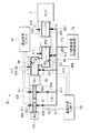
- FIG. 9 schematically shows a configuration example of a main part of a laser apparatus 3C according to the third embodiment.
- the EUV light generation system according to Embodiment 3 may include a laser device 3C instead of the laser device 3 in the EUV light generation system 11A according to the comparative example.
- the laser device 3C further includes a plurality of temperature sensors 412 as second temperature sensors in addition to the configuration of the laser device 3A according to the first embodiment.
- Each temperature sensor 412 is connected to the temperature measurement controller 52.
- the temperature sensor 412 is provided for each of the surrounding blocks 420 and measures the intake temperature of the purge gas introduced through the intake port 421 as the intake portion as the second temperature.
- the temperature measurement controller 52 Based on the temperature difference between the exhaust gas temperature as the first temperature measured by the temperature sensor 411 and the intake air temperature as the second temperature measured by the temperature sensor 412, the temperature measurement controller 52 Among the plurality of surrounding blocks 420, the surrounding block 420 in which abnormal heating has occurred is identified.
- the temperature measurement controller 52 uses, for example, the exhaust temperature as the first temperature measured by the temperature sensor 411 and the second temperature measured by the temperature sensor 412 for each enclosure block 420. Calculate the temperature difference from the intake air temperature. The temperature measurement controller 52 generates abnormal heating in the enclosure block 420 provided with the temperature sensor 411 in which the temperature difference is measured among the plurality of enclosure blocks 420 in the enclosure. Judge that you are doing.
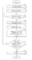
- FIG. 10 schematically shows a flowchart of a first example of the abnormal heating detection operation in the laser apparatus 3C.
- the temperature measurement controller 52 performs the following abnormal heating detection operation for each enclosure block 420. Thereby, the enclosure block 420 in which abnormal heating has occurred is identified among the plurality of enclosure blocks 420 in the enclosure.
- the temperature measurement controller 52 acquires the intake air temperature T1A by the temperature sensor 412 (step S201).
- the temperature measurement controller 52 acquires the exhaust gas temperature T1B by the temperature sensor 411 (step S202).
- the temperature measurement controller 52 determines whether or not the set time t has elapsed (step S203).
- the set time t may be, for example, 1 second or more and 10 seconds or less.
- the temperature measurement controller 52 repeats the determination in step S203 until the set time t has elapsed.
- step S20 determines that the set time t has elapsed (step S20). 3) Next, the intake air temperature T2A after the set time t has elapsed is acquired by the temperature sensor 412 (step S204). Next, the temperature measurement controller 52 uses the temperature sensor 411 to acquire the exhaust temperature T2B after the set time t has elapsed (step S205).
- the temperature measurement controller 52 determines whether or not the increase in temperature difference is equal to or greater than a predetermined threshold (step S207).
- the predetermined threshold may be 3 ° C., for example.
- the predetermined threshold value may be changed according to the flow rate of the purge gas supplied from the gas supply device 70.
- step S207 when it is determined that the increase in temperature difference is equal to or greater than the predetermined threshold (step S207; Y), the temperature measurement controller 52 causes abnormal heating in the surrounding block 420 where the increase in temperature difference is measured. (Step S208), the abnormal heating detection operation process is terminated.
- the temperature measurement controller 52 uses, for example, the exhaust temperature as the first temperature measured by the temperature sensor 411 and the second temperature measured by the temperature sensor 412 for each enclosure block 420. The rate of change in temperature difference from the intake air temperature may be calculated. Then, the temperature measurement controller 52 includes an outer block 420 provided with a temperature sensor 411 in which the change rate of the temperature difference is measured to be equal to or greater than a predetermined threshold among the plurality of outer blocks 420 in the outer envelope. It may be determined that abnormal heating has occurred.
- FIG. 11 schematically shows a flowchart of a second example of the abnormal heating detection operation in the laser apparatus 3C.
- the temperature measurement controller 52 performs the following abnormal heating detection operation for each enclosure block 420. Thereby, the enclosure block 420 in which abnormal heating has occurred is identified among the plurality of enclosure blocks 420 in the enclosure.
- the temperature measurement controller 52 determines whether or not the gradient of the temperature difference increase is greater than or equal to a predetermined threshold (step S212).
- the predetermined threshold may be, for example, 0.5 ° C./second.
- the predetermined threshold value may be changed according to the flow rate of the purge gas supplied from the gas supply device 70. If the temperature measurement controller 52 determines that the gradient of temperature difference increase is not equal to or greater than the predetermined threshold (step S212; N), the process returns to step S201.
- step S212 determines that the temperature difference increase gradient is equal to or greater than the predetermined threshold (step S212; Y)
- the temperature measurement controller 52 determines that the temperature difference increase gradient is measured in the surrounding block 420 where the temperature difference increase gradient is measured. It is determined that abnormal heating has occurred (step S213), and the abnormal heating detection operation process is terminated.
- the temperature measurement controller 52 transmits a signal indicating that abnormal heating has been detected to the EUV light generation controller 5. May be.
- the EUV light generation controller 5 may stop the light emission trigger signal S4 to the laser device 3C and stop the operation of the laser device 3C. Further, the EUV light generation controller 5 may display information on the surrounding block 420 in which the abnormality is specified on a display (not shown). Thus, the operator may check for damage to the optical element in the surrounding block 420 in which the abnormality is specified. When the optical element is damaged, the operator may replace the damaged optical element.
- the intake air temperature and the exhaust gas temperature are measured for each enclosure block 420, and the enclosure block 420 in which abnormal heating occurs is identified based on the temperature difference between them. As a result, the accuracy of the abnormal heating detection performance is further improved.
- Embodiment 4> Laser apparatus having a function of measuring the exhaust temperature of purge gas in the gap of the optical path tube
- a laser apparatus and an EUV light generation system according to Embodiment 4 of the present disclosure will be described.
- substantially the same components as those of the comparative example or the laser device according to any one of the first to third embodiments and the EUV light generation system are denoted by the same reference numerals, and description thereof is omitted as appropriate.
- FIG. 12 schematically illustrates a configuration example of a main part of a laser device 3D according to the fourth embodiment.
- the EUV light generation system according to Embodiment 4 may be configured to include a laser device 3D instead of the laser device 3 in the EUV light generation system 11A according to the comparative example.
- a gap 401 is formed in the connection portion between each outer block 420 of the optical path tube 400 and each of the amplifiers PA1, PA2 and the chamber 2 as in the laser device 3 according to the comparative example. Then, the purge gas is exhausted from the gap 401 of the optical path tube 400 for each outer block 420.
- the exhaust port 422 is provided as an exhaust part.
- the gap 401 is an exhaust part. At least one gap 401 is provided for each outer block 420.
- the temperature sensor 411 is provided in at least one gap 401 for each of the surrounding blocks 420.
- the temperature sensor 411 measures the first temperature of the atmosphere in each enclosure block 420 by measuring the exhaust temperature of the purge gas exhausted from the gap 401 for each enclosure block 420. .
- the purge gas is exhausted from the gap 401 of the optical path tube 400 for each outer block 420.
- the temperature sensor 411 measures the exhaust temperature of the purge gas exhausted from the gap 401 of the optical path tube 400.
- the detection operation of abnormal heating in the laser apparatus 3D may be substantially the same as that of the laser apparatus 3A according to the first embodiment.
- the abnormal heating detection operation shown in FIG. 5 or 6 may be performed.
- Embodiment 5> Laser apparatus having a function of measuring the temperature of purge gas inside the optical path tube
- a laser apparatus and an EUV light generation system according to Embodiment 5 of the present disclosure will be described.
- substantially the same components as those of the comparative example or the laser device according to any of Embodiments 1 to 4 and the EUV light generation system are denoted by the same reference numerals, and description thereof will be omitted as appropriate.
- FIG. 13 schematically illustrates a configuration example of a main part of a laser apparatus 3E according to the fifth embodiment.
- the EUV light generation system according to Embodiment 5 may include a laser device 3E instead of the laser device 3 in the EUV light generation system 11A according to the comparative example.
- a gap 401 is formed at the connection portion between each of the surrounding blocks 420 of the optical path tube 400 and each of the amplifiers PA1, PA2 and the chamber 2 as in the laser device 3 according to the comparative example. Then, the purge gas is exhausted from the gap 401 of the optical path tube 400 for each outer block 420.
- the exhaust port 422 is provided as an exhaust part.
- the gap 401 is an exhaust part. At least one gap 401 is provided for each outer block 420.
- At least one temperature sensor 411 is provided for each outer block 420 inside the optical path tube 400.
- the temperature sensor 411 is spaced from the optical elements such as the optical isolator 81 and the high reflection mirrors 96 and 97 inside the optical path tube 400.
- the temperature sensor 411 measures the temperature of the purge gas at a position away from the optical element inside the optical path tube 400 for each of the surrounding blocks 420.
- the operation for detecting abnormal heating in the laser apparatus 3E may be substantially the same as that of the laser apparatus 3A according to the first embodiment.
- the abnormal heating detection operation shown in FIG. 5 or 6 may be performed.
Landscapes
- Physics & Mathematics (AREA)
- Electromagnetism (AREA)
- Optics & Photonics (AREA)
- Engineering & Computer Science (AREA)
- Plasma & Fusion (AREA)
- Exposure And Positioning Against Photoresist Photosensitive Materials (AREA)
Abstract
本開示によるレーザ装置は、レーザ光路上に配置された光学素子と、光学素子から離れた位置にあるガスの第1の温度を計測する第1の温度センサとを含み、レーザ光路の一部を覆う複数の外囲ブロックと、複数の外囲ブロックを含み、レーザ光路を覆うよう構成された外囲体と、各々の第1の温度センサに接続され、外囲体において第1の温度の上昇が計測された外囲ブロックを、異常が発生している外囲ブロックとして特定する制御部とを備える。
Description
本開示は、レーザ装置、及びEUV光生成システムに関する。
近年、半導体プロセスの微細化に伴って、半導体プロセスの光リソグラフィにおける転写パターンの微細化が急速に進展している。次世代においては、20nm以下の微細加工が要求されるようになる。このため、波長13nm程度の極端紫外(EUV)光を生成するための装置と縮小投影反射光学系とを組み合わせた露光装置の開発が期待されている。
EUV光生成装置としては、ターゲット物質にレーザ光を照射することによって生成されるプラズマが用いられるLPP(Laser Produced Plasma)式の装置と、放電によって生成されるプラズマが用いられるDPP(Discharge Produced Plasma)式の装置と、軌道放射光が用いられるSR(Synchrotron Radiation)式の装置との3種類の装置が提案されている。
本開示の第1のレーザ装置は、レーザ光路上に配置された光学素子と、光学素子から離れた位置にあるガスの第1の温度を計測する第1の温度センサとを含み、レーザ光路の一部を覆う複数の外囲ブロックと、複数の外囲ブロックを含み、レーザ光路を覆うよう構成された外囲体と、各々の第1の温度センサに接続され、外囲体において第1の温度の上昇が計測された外囲ブロックを、異常が発生している外囲ブロックとして特定する制御部とを備える。
本開示の第2のレーザ装置は、レーザ光路上に配置された光学素子と、光学素子を覆う光路管であって、内部にパージガスを導入する吸気部と、内部からパージガスを排気する排気部と、排気部から排気されたパージガスの第1の温度を計測する第1の温度センサとを含む複数の光路管と、複数の光路管によってレーザ光路を覆うように構成された外囲体と、各々の第1の温度センサに接続され、外囲体において第1の温度の上昇が計測された光路管を異常が発生している光路管として特定する制御部とを備える。
本開示の第2のレーザ装置は、レーザ光路上に配置された光学素子と、光学素子を覆う光路管であって、内部にパージガスを導入する吸気部と、内部からパージガスを排気する排気部と、排気部から排気されたパージガスの第1の温度を計測する第1の温度センサとを含む複数の光路管と、複数の光路管によってレーザ光路を覆うように構成された外囲体と、各々の第1の温度センサに接続され、外囲体において第1の温度の上昇が計測された光路管を異常が発生している光路管として特定する制御部とを備える。
本開示の第1のEUV光生成システムは、EUV光が生成されるEUVチャンバと、EUVチャンバに向けてレーザ光を出射するレーザ装置とを含み、レーザ装置は、レーザ光路上に配置された光学素子と、光学素子から離れた位置にあるガスの第1の温度を計測する第1の温度センサとを含み、レーザ光路の一部を覆う複数の外囲ブロックと、複数の外囲ブロックを含み、レーザ光路を覆うよう構成された外囲体と、各々の第1の温度センサに接続され、外囲体において第1の温度の上昇が計測された外囲ブロックを、異常が発生している外囲ブロックとして特定する制御部とを備える。
本開示の第2のEUV光生成システムは、EUV光が生成されるEUVチャンバと、EUVチャンバに向けてレーザ光を出射するレーザ装置とを含み、レーザ装置は、レーザ光路上に配置された光学素子と、光学素子を覆う光路管であって、内部にパージガスを導入する吸気部と、内部からパージガスを排気する排気部と、排気部から排気されたパージガスの第1の温度を計測する第1の温度センサとを含む複数の光路管と、複数の光路管によってレーザ光路を覆うように構成された外囲体と、各々の第1の温度センサに接続され、外囲体において第1の温度の上昇が計測された光路管を異常が発生している光路管として特定する制御部とを備える。
本開示の第2のEUV光生成システムは、EUV光が生成されるEUVチャンバと、EUVチャンバに向けてレーザ光を出射するレーザ装置とを含み、レーザ装置は、レーザ光路上に配置された光学素子と、光学素子を覆う光路管であって、内部にパージガスを導入する吸気部と、内部からパージガスを排気する排気部と、排気部から排気されたパージガスの第1の温度を計測する第1の温度センサとを含む複数の光路管と、複数の光路管によってレーザ光路を覆うように構成された外囲体と、各々の第1の温度センサに接続され、外囲体において第1の温度の上昇が計測された光路管を異常が発生している光路管として特定する制御部とを備える。
本開示のいくつかの実施形態を、単なる例として、添付の図面を参照して以下に説明する。
図1は、例示的なLPP式のEUV光生成システムの一構成例を概略的に示す。
図2は、比較例に係るEUV光生成システムの一構成例を概略的に示す。
図3は、比較例に係るEUV光生成システムにおけるレーザ装置の要部の構成例を概略的に示す。
図4は、実施形態1に係るレーザ装置の要部の構成例を概略的に示す。
図5は、実施形態1に係るレーザ装置における異常加熱の検知動作の第1の例のフローチャートを概略的に示す。
図6は、実施形態1に係るレーザ装置における異常加熱の検知動作の第2の例のフローチャートを概略的に示す。
図7は、実施形態1の変形例に係るレーザ装置の要部の構成例を概略的に示す。
図8は、実施形態2に係るレーザ装置における異常加熱の検知動作のフローチャートの第1の例を概略的に示す。
図9は、実施形態3に係るレーザ装置の要部の構成例を概略的に示す。
図10は、実施形態3に係るレーザ装置における異常加熱の検知動作の第1の例のフローチャートを概略的に示す。
図11は、実施形態3に係るレーザ装置における異常加熱の検知動作の第2の例のフローチャートを概略的に示す。
図12は、実施形態4に係るレーザ装置の要部の構成例を概略的に示す。
図13は、実施形態5に係るレーザ装置の要部の構成例を概略的に示す。
<内容>
<1.EUV光生成装置の全体説明>(図1)
1.1 構成
1.2 動作
<2.比較例>(異常加熱の検知機能を備えたEUV光生成システム)(図2~図3)
2.1 比較例に係るEUV光生成システム
2.1.1 構成
2.1.2 動作
2.2 比較例に係るレーザ装置
2.2.1 構成
2.2.2 動作
2.3 課題
<3.実施形態1>(パージガスの排気温度を計測する機能を備えたレーザ装置)(図4~図7)
3.1 構成
3.2 動作
3.3 作用・効果
3.4 変形例
<4.実施形態2>(ガス供給装置から供給されるパージガスの温度を計測する機能を備えたレーザ装置)(図8)
4.1 構成
4.2 動作
4.3 作用・効果
<5.実施形態3>(パージガスの吸気温度を計測する機能を備えたレーザ装置)(図9~図11)
5.1 構成
5.2 動作
5.3 作用・効果
<6.実施形態4>(光路管の隙間においてパージガスの排気温度を計測する機能を備えたレーザ装置)(図12)
6.1 構成
6.2 動作
6.3 作用・効果
<7.実施形態5>(光路管の内部においてパージガスの温度を計測する機能を備えたレーザ装置)(図13)
7.1 構成
7.2 動作、及び作用・効果
<8.その他>
<1.EUV光生成装置の全体説明>(図1)
1.1 構成
1.2 動作
<2.比較例>(異常加熱の検知機能を備えたEUV光生成システム)(図2~図3)
2.1 比較例に係るEUV光生成システム
2.1.1 構成
2.1.2 動作
2.2 比較例に係るレーザ装置
2.2.1 構成
2.2.2 動作
2.3 課題
<3.実施形態1>(パージガスの排気温度を計測する機能を備えたレーザ装置)(図4~図7)
3.1 構成
3.2 動作
3.3 作用・効果
3.4 変形例
<4.実施形態2>(ガス供給装置から供給されるパージガスの温度を計測する機能を備えたレーザ装置)(図8)
4.1 構成
4.2 動作
4.3 作用・効果
<5.実施形態3>(パージガスの吸気温度を計測する機能を備えたレーザ装置)(図9~図11)
5.1 構成
5.2 動作
5.3 作用・効果
<6.実施形態4>(光路管の隙間においてパージガスの排気温度を計測する機能を備えたレーザ装置)(図12)
6.1 構成
6.2 動作
6.3 作用・効果
<7.実施形態5>(光路管の内部においてパージガスの温度を計測する機能を備えたレーザ装置)(図13)
7.1 構成
7.2 動作、及び作用・効果
<8.その他>
以下、本開示の実施形態について、図面を参照しながら詳しく説明する。
以下に説明される実施形態は、本開示のいくつかの例を示すものであって、本開示の内容を限定するものではない。また、各実施形態で説明される構成及び動作の全てが本開示の構成及び動作として必須であるとは限らない。
なお、同一の構成要素には同一の参照符号を付して、重複する説明を省略する。
以下に説明される実施形態は、本開示のいくつかの例を示すものであって、本開示の内容を限定するものではない。また、各実施形態で説明される構成及び動作の全てが本開示の構成及び動作として必須であるとは限らない。
なお、同一の構成要素には同一の参照符号を付して、重複する説明を省略する。
<1.EUV光生成装置の全体説明>
[1.1 構成]
図1に、例示的なLPP式のEUV光生成システムの構成を概略的に示す。EUV光生成装置1は、少なくとも1つのレーザ装置3と共に用いられる場合がある。本願においては、EUV光生成装置1及びレーザ装置3を含むシステムを、EUV光生成システム11と称する。図1に示し、かつ、以下に詳細に説明するように、EUV光生成装置1は、チャンバ2、ターゲット供給部26を含む。チャンバ2は、密閉可能な容器である。ターゲット供給部26は、ターゲット物質をチャンバ2内部に供給するよう構成され、例えば、チャンバ2の壁を貫通するように取り付けられる。ターゲット物質の材料は、スズ、テルビウム、ガドリニウム、リチウム、キセノン、又は、それらの内のいずれか2つ以上の組み合せを含んでもよいが、これらに限定されない。
[1.1 構成]
図1に、例示的なLPP式のEUV光生成システムの構成を概略的に示す。EUV光生成装置1は、少なくとも1つのレーザ装置3と共に用いられる場合がある。本願においては、EUV光生成装置1及びレーザ装置3を含むシステムを、EUV光生成システム11と称する。図1に示し、かつ、以下に詳細に説明するように、EUV光生成装置1は、チャンバ2、ターゲット供給部26を含む。チャンバ2は、密閉可能な容器である。ターゲット供給部26は、ターゲット物質をチャンバ2内部に供給するよう構成され、例えば、チャンバ2の壁を貫通するように取り付けられる。ターゲット物質の材料は、スズ、テルビウム、ガドリニウム、リチウム、キセノン、又は、それらの内のいずれか2つ以上の組み合せを含んでもよいが、これらに限定されない。
チャンバ2の壁には、少なくとも1つの貫通孔が設けられている。その貫通孔は、ウインドウ21によって塞がれ、ウインドウ21をレーザ装置3から出力されるパルスレーザ光32が透過する。チャンバ2の内部には、例えば、回転楕円面形状の反射面を有するEUV集光ミラー23が配置される。EUV集光ミラー23は、第1及び第2の焦点を有する。EUV集光ミラー23の表面には、例えば、モリブデンとシリコンとが交互に積層された多層反射膜が形成される。EUV集光ミラー23は、例えば、その第1の焦点がプラズマ生成領域25に位置し、その第2の焦点が中間集光点(IF)292に位置するように配置されてもよい。EUV集光ミラー23の中央部には貫通孔24が設けられ、貫通孔24をパルスレーザ光33が通過する。
EUV光生成装置1は、EUV光生成コントローラ5、ターゲットセンサ4等を含む。ターゲットセンサ4は、ターゲット27の存在、軌跡、位置、速度のうちいずれか又は複数を検出するよう構成される。ターゲットセンサ4は、撮像機能を備えてもよい。
また、EUV光生成装置1は、チャンバ2の内部と露光装置6の内部とを連通させる接続部29を含む。接続部29内部には、アパーチャ293が形成された壁291が設けられる。壁291は、そのアパーチャ293がEUV集光ミラー23の第2の焦点位置に位置するように配置される。
さらに、EUV光生成装置1は、レーザ光伝送装置34、レーザ光集光ミラー22、ターゲット27を回収するためのターゲット回収部28等を含む。レーザ光伝送装置34は、レーザ光の伝送状態を規定するための光学素子と、この光学素子の位置、姿勢等を調整するためのアクチュエータとを備える。
[1.2 動作]
図1を参照して、例示的なLPP式のEUV光生成システムの動作を説明する。レーザ装置3から出力されたパルスレーザ光31は、レーザ光伝送装置34を経て、パルスレーザ光32としてウインドウ21を透過してチャンバ2内に入射する。パルスレーザ光32は、少なくとも1つのレーザ光経路に沿ってチャンバ2内を進み、レーザ光集光ミラー22で反射されて、パルスレーザ光33として少なくとも1つのターゲット27に照射される。
図1を参照して、例示的なLPP式のEUV光生成システムの動作を説明する。レーザ装置3から出力されたパルスレーザ光31は、レーザ光伝送装置34を経て、パルスレーザ光32としてウインドウ21を透過してチャンバ2内に入射する。パルスレーザ光32は、少なくとも1つのレーザ光経路に沿ってチャンバ2内を進み、レーザ光集光ミラー22で反射されて、パルスレーザ光33として少なくとも1つのターゲット27に照射される。
ターゲット供給部26は、ターゲット物質によって形成されたターゲット27をチャンバ2内部のプラズマ生成領域25に向けて出力するよう構成される。ターゲット27には、パルスレーザ光33に含まれる少なくとも1つのパルスが照射される。パルスレーザ光が照射されたターゲット27はプラズマ化し、そのプラズマから放射光251が放射される。放射光251に含まれるEUV光252は、EUV集光ミラー23によって選択的に反射される。EUV集光ミラー23によって反射されたEUV光252は、中間集光点292で集光され、露光装置6に出力さる。なお、1つのターゲット27に、パルスレーザ光33に含まれる複数のパルスが照射されてもよい。
EUV光生成コントローラ5は、EUV光生成システム11全体の制御を統括するよう構成される。EUV光生成コントローラ5は、ターゲットセンサ4の検出結果を処理するよう構成される。ターゲットセンサ4の検出結果に基づいて、EUV光生成コントローラ5は、例えば、ターゲット27が出力されるタイミング、ターゲット27の出力方向等を制御するよう構成されてもよい。さらに、EUV光生成コントローラ5は、例えば、レーザ装置3の発振タイミング、パルスレーザ光32の進行方向、パルスレーザ光33の集光位置等を制御するよう構成されてもよい。上述の様々な制御は単なる例示に過ぎず、必要に応じて他の制御が追加されてもよい。
<2.比較例>(異常加熱の検知機能を備えたEUV光生成システム)
[2.1 比較例に係るEUV光生成システム]
[2.1.1 構成]
図2は、比較例に係るEUV光生成システム11Aの一構成例を概略的に示している。なお、以下では図1に示したEUV光生成システム11の構成要素と略同じ部分については、同一符号を付し、適宜説明を省略する。
[2.1 比較例に係るEUV光生成システム]
[2.1.1 構成]
図2は、比較例に係るEUV光生成システム11Aの一構成例を概略的に示している。なお、以下では図1に示したEUV光生成システム11の構成要素と略同じ部分については、同一符号を付し、適宜説明を省略する。
EUV光生成システム11Aは、チャンバ2と、レーザ装置3と、レーザ光伝送装置34と、EUV光生成コントローラ5とを含んでもよい。
レーザ装置3は、マスタオシレータ(MO)110と、光アイソレータ81と、高反射ミラー82と、複数の増幅器PA1,PA2,PA3,PA4と、複数のPA電源121,122,123,124と、レーザ制御部51とを含んでよい。
レーザ制御部51は、EUV光生成コントローラ5に接続されている。
レーザ装置3はさらに、レーザ光路上に設けられた複数の光学素子を含んでもよい。レーザ光路上に設けられた複数の光学素子は、光アイソレータ81や高反射ミラー82の他、不図示の光学素子を含んでもよい。複数の光学素子は、レーザ光の伝送およびレーザ光の整形のうち、少なくとも一方を行うように構成されてよい。
マスタオシレータ110と増幅器PA1,PA2,PA3,PA4は、MOPA(Master Oscillator Power Amplifier)を構成してよい。増幅器PA1,PA2,PA3,PA4はそれぞれ、マスタオシレータ110が光アイソレータ81と高反射ミラー82とを介して出力するレーザ光路上に配置されてよい。増幅器PA1,PA2,PA3,PA4はそれぞれ、PA電源121,122,123,124に接続されてもよい。増幅器PA1,PA2,PA3,PA4はそれぞれ、レーザ光を増幅するレーザチャンバ60と、レーザ光が入力する入力ウインドウ61aと、レーザ光を出力する出力ウインドウ61bとを含んでもよい。レーザチャンバ60は、放電用の内部電極を含んでもよい。
PA電源121,122,123,124はそれぞれ、レーザ制御部51に接続されている。
光アイソレータ81は、マスタオシレータ110から増幅器PA1までのレーザ光路上に配置されてもよい。光アイソレータ81は、レーザ制御部51からの指示によって開閉動作し、レーザ光の透過と遮断とを行うよう構成されてよい。
レーザ光伝送装置34は、レーザ装置3とチャンバ2との間の経路に配置された伝送光学系を含んでいる。この伝送光学系は、複数の高反射ミラー91,92と、ビーム調節装置90とを含んでもよい。
チャンバ2は、ターゲットセンサ4と、ウインドウ21と、EUV光集光ミラー23と、ターゲット供給部26と、ターゲット回収部28と、レーザ集光光学系94と、ミラー保持部材95と、ダンパミラー130と、ビームダンプ装置131とを含んでいてもよい。
ビーム調節装置90は、レーザ光伝送装置34からレーザ集光光学系94に至るレーザ光路上に配置されてもよい。ビーム調節装置90は、レーザ制御部51からの発散角制御信号S5の指示によってレーザ光の発散角を調節するよう構成されてよい。
マスタオシレータ110からチャンバ2に至るレーザ光路は、複数の光路管400によってほぼ全体が覆われていてもよい。光路管400は、レーザ光路を構成する光学素子の一部又は全体を覆うように構成されてもよい。光路管400は、ガス供給路71を介してガス供給装置70に接続されてもよい。ガス供給装置70は、ガス供給路71を介して光路管400の内部にパージガスを供給してもよい。
レーザ集光光学系94は、チャンバ2に入射したパルスレーザ光33をプラズマ生成領域25に集光するよう構成されてもよい。レーザ集光光学系94は、レーザ集光ミラー22と凸面ミラー93とを含んでよい。
ミラー保持部材95は、チャンバ2に固定され、EUV集光ミラー23とレーザ集光光学系94とを保持してもよい。EUV集光ミラー23は適当なホルダを介して保持されてもよい。
ダンパミラー130は、プラズマ生成領域25の下流におけるレーザ光路上に配置され、プラズマ生成領域25を通過したパルスレーザ光33をビームダンプ装置131に向けて反射するよう構成されていてもよい。
ビームダンプ装置131は、ダンパミラー130で反射されたパルスレーザ光33が入射する位置に配置されてもよい。パルスレーザ光33はチャンバ壁に配置されたビームダンプ装置131に入射してもよい。ビームダンプ装置131は冷却装置132に接続されてもよい。
[2.1.2 動作]
EUV光生成システム11Aは、露光装置6の露光装置制御部6aからのEUV光出力指令信号S1に基づいて、EUV光252を出力してもよい。EUV光生成コントローラ5は、EUV光出力指令信号S1に基づいて、ターゲット供給部26にターゲット出力信号S3を送信し、ターゲット27を出力させてもよい。
EUV光生成システム11Aは、露光装置6の露光装置制御部6aからのEUV光出力指令信号S1に基づいて、EUV光252を出力してもよい。EUV光生成コントローラ5は、EUV光出力指令信号S1に基づいて、ターゲット供給部26にターゲット出力信号S3を送信し、ターゲット27を出力させてもよい。
ターゲットセンサ4は、ターゲット27を検出し、ターゲット検出信号S2をEUV光生成コントローラ5に出力してもよい。
EUV光生成コントローラ5は、ターゲット検出信号S2に対して所定の遅延時間を付加して生成する発光トリガ信号S4をレーザ装置3のレーザ制御部51に出力してもよい。
レーザ制御部51は、発光トリガ信号S4が入力されると、マスタオシレータ110にレーザ出力信号を出力し得る。これに先立って、レーザ制御部51は、PA電源121,122,123,124をオンしてもよい。これにより、PA電源121,122,123,124は、増幅器PA1,PA2,PA3,PA4のそれぞれの内部電極に電圧または電流を供給し、増幅器PA1,PA2,PA3,PA4のそれぞれを増幅可能な状態としてもよい。
マスタオシレータ110は、レーザ制御部51からのレーザ出力信号に同期してパルスレーザ光を出力し得る。これに同期してレーザ制御部51は、光アイソレータ81を開状態にしてもよい。マスタオシレータ110から出力されたパルスレーザ光は、増幅器PA1,PA2,PA3,PA4によって増幅されレーザ光伝送装置34を経由して、ビーム調節装置90に入射し得る。ビーム調節装置90は、入射したパルスレーザ光の発散角を調節して出力してもよい。ビーム調節装置90から出力されたパルスレーザ光は、ウインドウ21を通過した後、チャンバ2に入力され得る。レーザ装置3から出力されるパルスレーザ光は数kW~数十kWに達する。
チャンバ2に入力したパルスレーザ光は、レーザ集光光学系94によってプラズマ生成領域25に到達したターゲット27に集光照射される。これにより、EUV光252を含む放射光251を得ることができる。このとき、パルスレーザ光の照射径は、ターゲット27の径より大きくてもよい。パルスレーザ光33の一部はターゲット27に照射されずに、ダンパミラー130に入射してもよい。
ダンパミラー130によって反射されたパルスレーザ光33は、ビームダンプ装置131で吸収され熱に変換される。この際発生する熱は、冷却装置132によって外部に排出される。
[2.2 比較例に係るレーザ装置]
[2.2.1 構成]
図3は、比較例に係るEUV光生成システム11Aにおけるレーザ装置3の要部の構成例を概略的に示している。なお、図3では、説明を簡便にするため、レーザ光伝送装置34の図示を省略している。また、図3では、2つの増幅器PA1,PA2のみを図示しているが、増幅器が3つ以上、設けられていてもよい。
[2.2.1 構成]
図3は、比較例に係るEUV光生成システム11Aにおけるレーザ装置3の要部の構成例を概略的に示している。なお、図3では、説明を簡便にするため、レーザ光伝送装置34の図示を省略している。また、図3では、2つの増幅器PA1,PA2のみを図示しているが、増幅器が3つ以上、設けられていてもよい。
マスタオシレータ110からチャンバ2のウインドウ21に至るレーザ光路上には、光アイソレータ81と、増幅器PA1と、高反射ミラー96,97と、増幅器PA2とが順に、配置されていてもよい。
高反射ミラー96は、ホルダ98によって保持されている。高反射ミラー97は、ホルダ99によって保持されている。
マスタオシレータ110からチャンバ2に至るレーザ光路は、複数の光路管400によってほぼ全体が覆われている。光路管400は、光アイソレータ81や高反射ミラー96,97等、レーザ光路を構成する複数の光学素子を覆ってもよい。
光路管400は、複数のブロックに分割されていてもよい。光路管400は、外部と連通する排気孔を備える。排気孔は光路管400の各ブロックと各増幅器PA1,PA2やチャンバ2との接続部における隙間401によって形成されてもよい。排気孔は光路管400の全ブロックではなく一部のブロックが備えていてもよい。また、光路管400の各ブロックと各増幅器PA1,PA2やチャンバ2との接続部は、ウインドウによって一端が閉鎖されてもよい。
ガス供給装置70は、メイン供給路71Aと、メイン供給路71Aから分岐した複数の分岐供給路71Bとを介して、光路管400の内部にパージガスを供給する。光路管400の各ブロックには分岐供給路71Bを構成する配管が連結される。
レーザ装置3は、温度センサ410と、温度計測コントローラ52とをさらに備えていてもよい。
温度センサ410は、例えば、レーザ光路上に配置されたレンズやミラー等の光学素子や、その光学素子を保持する保持部材に設けられてもよい。レーザ光路上に配置された光学素子は、例えば光アイソレータ81、増幅器PA1,PA2の入力ウインドウ61a及び出力ウインドウ61b、高反射ミラー96,97、並びにチャンバ2のウインドウ21等であってもよい。光学素子を保持する保持部材は、例えば高反射ミラー96,97を保持するホルダ98,99等であってもよい。
温度計測コントローラ52は、温度センサ410による温度の計測結果に基づいて、光学素子や保持部材の異常加熱を検知してもよい。
[2.2.2 動作]
ガス供給装置70は、メイン供給路71Aと複数の分岐供給路71Bとを介して、光路管400の内部にパージガスを供給する。ガス供給装置70は、パージガスとして、CDA(乾燥空気,乾燥圧縮空気(Clean Dry Air, Compressed Dry Air))を供給するCDA供給装置であってもよい。CDAは、露点温度-70℃以下に管理された乾燥空気であってもよい。ガス供給装置70によって供給されるパージガスの流量は、光路管400の各ブロックごとに、例えば10分程度でパージガスが入れ代わる流量となるように設定してもよい。例えばパージガスとして、CDAを供給する場合、流量は200L~300L/minであってもよい。
ガス供給装置70は、メイン供給路71Aと複数の分岐供給路71Bとを介して、光路管400の内部にパージガスを供給する。ガス供給装置70は、パージガスとして、CDA(乾燥空気,乾燥圧縮空気(Clean Dry Air, Compressed Dry Air))を供給するCDA供給装置であってもよい。CDAは、露点温度-70℃以下に管理された乾燥空気であってもよい。ガス供給装置70によって供給されるパージガスの流量は、光路管400の各ブロックごとに、例えば10分程度でパージガスが入れ代わる流量となるように設定してもよい。例えばパージガスとして、CDAを供給する場合、流量は200L~300L/minであってもよい。
ガス供給装置70から供給されたパージガスはレーザ光路を流れ、排気孔から外部に排気される。パージガスを流す目的は、清浄なパージガスをレーザ光路に流し、レーザ光路を構成する光学素子の結露や吸湿による劣化を抑制することであってもよい。
光アイソレータ81や高反射ミラー96,97等の光学素子に損傷が生じたり、レーザ光軸ずれなどの装置異常が起こると、光学素子自体や、光学素子の保持部材などが加熱し、温度上昇が生じる。よって、温度センサ410によって光学素子やその保持部材の温度を計測し、温度計測コントローラ52が、その温度上昇を監視することで、装置異常を早期に発見することができる。温度計測コントローラ52は、EUV光生成コントローラ5に接続され、異常加熱が検知されたことを示す信号をEUV光生成コントローラ5に送信してもよい。温度計測コントローラ52によって異常加熱が検知された場合、EUV光生成コントローラ5は、不図示の表示器に警報を表示してレーザ装置3を停止してもよい。
[2.3 課題]
図3の比較例に係るレーザ装置3では、異常加熱した箇所を特定するためには、個々の光学素子や保持部材に温度センサ410を配置することが考えられるが、その場合、レーザ装置3及びEUV光生成システム11Aの構成が複雑化し得る。レーザ装置3及びEUV光生成システム11Aでは、一般に数十個以上の光学素子が存在する。さらに光学素子の保持部材まで含めると、異常加熱した箇所を特定するために、数百カ所前後の温度を測る必要があり得る。このため、比較例に係るレーザ装置3では、レーザ装置3及びEUV光生成システム11Aの肥大化と煩雑化とが生じ得る。また、これに関連し、温度センサ410を多数設置した場合、メンテナンス時の分解や組み立てに時間がかかり、メンテナンス性が悪化し得る。
図3の比較例に係るレーザ装置3では、異常加熱した箇所を特定するためには、個々の光学素子や保持部材に温度センサ410を配置することが考えられるが、その場合、レーザ装置3及びEUV光生成システム11Aの構成が複雑化し得る。レーザ装置3及びEUV光生成システム11Aでは、一般に数十個以上の光学素子が存在する。さらに光学素子の保持部材まで含めると、異常加熱した箇所を特定するために、数百カ所前後の温度を測る必要があり得る。このため、比較例に係るレーザ装置3では、レーザ装置3及びEUV光生成システム11Aの肥大化と煩雑化とが生じ得る。また、これに関連し、温度センサ410を多数設置した場合、メンテナンス時の分解や組み立てに時間がかかり、メンテナンス性が悪化し得る。
また、比較例に係るレーザ装置3は、計測精度と診断正確性の点で劣っている。レーザ装置3において、異常時に発熱するのは、光学素子及び保持部材の表面である。保持部材であれば、表面計測はたやすいが、光学素子においては、表面はレーザ反射面であり、この表面には計測器等の設置がほぼ不可能である。よって、光学素子の側面や背面を計測することになるが、表面の発熱が側面や背面に反映されるまでに時間が掛かったりするので、計測精度と診断正確性が低下し得る。
<3.実施形態1>(パージガスの排気温度を計測する機能を備えたレーザ装置)
次に、本開示の実施形態1に係るレーザ装置、及びEUV光生成システムについて説明する。なお、以下では上記比較例に係るレーザ装置3、及びEUV光生成システム11Aの構成要素と略同じ部分については、同一符号を付し、適宜説明を省略する。
次に、本開示の実施形態1に係るレーザ装置、及びEUV光生成システムについて説明する。なお、以下では上記比較例に係るレーザ装置3、及びEUV光生成システム11Aの構成要素と略同じ部分については、同一符号を付し、適宜説明を省略する。
[3.1 構成]
図4は、実施形態1に係るレーザ装置3Aの要部の構成例を概略的に示している。
図4は、実施形態1に係るレーザ装置3Aの要部の構成例を概略的に示している。
実施形態1に係るEUV光生成システムは、上記比較例に係るEUV光生成システム11Aにおけるレーザ装置3に代えてレーザ装置3Aを備えた構成であってもよい。
レーザ装置3Aは、上記比較例に係るレーザ装置3における温度センサ410に代えて、第1の温度センサとしての温度センサ411を備えている。温度センサ411は、熱電対であってもよい。
レーザ装置3Aは、マスタオシレータ110からチャンバ2に至るレーザ光路を取り囲むように設けられた外囲体を備えている。外囲体は、複数の光路管400によって構成されていてもよい。外囲体は、レーザ光路に沿って設けられた複数の外囲ブロック420を含んでいる。各外囲ブロック420は、マスタオシレータ110からチャンバ2に至るレーザ光路の一部を覆うよう構成されていてもよい。外囲体は、複数の外囲ブロック420を配置することで、マスタオシレータ110からチャンバ2に至るレーザ光路を覆うよう構成されていてもよい。複数の外囲ブロック420にはそれぞれ、光アイソレータ81や高反射ミラー96,97等の少なくとも1つの光学素子が設けられている。光路管400の各外囲ブロック420と各増幅器PA1,PA2やチャンバ2との接続部には、比較例に係るレーザ装置3のように隙間401が形成されていてもよい。図4の構成例では、隙間401が形成されていない例を示している。
光路管400は、吸気部としての吸気ポート421と排気部としての排気ポート422とを備えている。吸気ポート421は、各外囲ブロック420ごとに少なくとも1つ設けられている。吸気ポート421は、各外囲ブロック420ごとに分岐供給路71Bに連結され、メイン供給路71A及び分岐供給路71Bを介してガス供給装置70からのパージガスを光路管400の内部に導入する。排気ポート422は、各外囲ブロック420ごとに少なくとも1つ設けられ、各外囲ブロック420ごとに、光路管400の内部からパージガスを排気する。
温度センサ411は、各外囲ブロック420ごとに少なくとも1つ設けられると共に、光アイソレータ81や高反射ミラー96,97等の光学素子、及びホルダ98,99等に対して離間配置されている。温度センサ411は、光学素子から離れた位置にあるガスの第1の温度を計測する第1の温度センサであってもよい。また、温度センサ411は、高反射ミラー96,97を保持するホルダ98,99等からも離れた位置にあるガスの第1の温度を計測する。ここでいうガスとは、パージガスを含んでもよい。レーザ装置3Aでは、温度センサ411が、各外囲ブロック420ごとに、排気ポート422から排気されたパージガスの排気温度を計測することによって、各外囲ブロック420内の雰囲気の第1の温度を計測する。
温度計測コントローラ52は、各温度センサ411に接続され、各温度センサ411による計測結果に基づいて、外囲体において排気温度の上昇が計測された外囲ブロック420を、異常が発生している外囲ブロック420として特定する制御部であってもよい。また、温度計測コントローラ52は、各温度センサ411に接続され、各温度センサ411による計測結果に基づいて、外囲体において排気温度の上昇が計測された光路管400を、異常が発生している光路管400として特定する制御部であってもよい。
以下、実施形態1では、温度計測コントローラ52が、異常が発生している外囲ブロック420を特定する場合を例として説明する。後述の実施形態についても、異常が発生している外囲ブロック420を特定する場合を例として説明する。
以下、実施形態1では、温度計測コントローラ52が、異常が発生している外囲ブロック420を特定する場合を例として説明する。後述の実施形態についても、異常が発生している外囲ブロック420を特定する場合を例として説明する。
その他の構成は、上記比較例に係るレーザ装置3、及びEUV光生成システム11Aと略同様であってもよい。
[3.2 動作]
ガス供給装置70は、メイン供給路71Aと、吸気ポート421に連結された複数の分岐供給路71Bとを介して、光路管400の各外囲ブロック420の内部にパージガスを供給する。
ガス供給装置70は、メイン供給路71Aと、吸気ポート421に連結された複数の分岐供給路71Bとを介して、光路管400の各外囲ブロック420の内部にパージガスを供給する。
ガス供給装置70から供給されたパージガスは、各外囲ブロック420ごとにレーザ光路を流れ、各排気ポート422から光路管400の外部に排気される。
光アイソレータ81や高反射ミラー96,97等の光学素子に損傷が生じたり、レーザ光軸ずれなどの装置異常が起こると、光学素子自体や、光学素子の保持部材などが加熱し、温度上昇が生じる。その際に、ガス温度も上昇するため、排気ポート422から排気されたパージガスの排気温度を温度センサ411によって計測することによって、異常加熱を検知できる。
(異常加熱の検知動作の第1の例)
レーザ装置3Aでは、各外囲ブロック420ごとに、温度センサ411によって第1の温度としての排気温度が計測される。温度計測コントローラ52は、外囲体において複数の外囲ブロック420のうち、排気温度が所定の閾値以上となったことが計測された温度センサ411が設けられた外囲ブロック420に異常加熱が発生していると判断する。
レーザ装置3Aでは、各外囲ブロック420ごとに、温度センサ411によって第1の温度としての排気温度が計測される。温度計測コントローラ52は、外囲体において複数の外囲ブロック420のうち、排気温度が所定の閾値以上となったことが計測された温度センサ411が設けられた外囲ブロック420に異常加熱が発生していると判断する。
図5は、レーザ装置3Aにおける異常加熱の検知動作の第1の例のフローチャートを概略的に示している。なお、温度計測コントローラ52は、以下の異常加熱の検知動作を、各外囲ブロック420ごとに行う。これにより、外囲体において複数の外囲ブロック420のうち、異常加熱が発生している外囲ブロック420の特定を行う。
まず、温度計測コントローラ52は、温度センサ411によって排気温度T1を取得する(ステップS101)。
次に、温度計測コントローラ52は、設定時間tが経過したか否かを判断する(ステップS102)。設定時間tは、例えば1秒以上、10秒以下の時間であってもよい。温度計測コントローラ52は、設定時間tが経過していないと判断した場合(ステップS102;N)には、設定時間tが経過するまでステップS102の判断を繰り返す。
温度計測コントローラ52は、設定時間tが経過したと判断した場合(ステップS102;Y)には、次に、温度センサ411によって、設定時間t経過後の排気温度T2を取得する(ステップS103)。
次に、温度計測コントローラ52は、設定時間t経過後の排気温度T2と設定時間t経過前の排気温度T1との温度差(T2-T1)を計算することによって、設定時間t経過後の温度上昇を計算する(ステップS104)。
次に、温度計測コントローラ52は、温度上昇が所定の閾値以上であるか否かを判断する(ステップS105)。ここで、所定の閾値は、例えば3℃であってもよい。この所定の閾値は、ガス供給装置70から供給されるパージガスの流量に応じて変化させてもよい。温度計測コントローラ52は、温度上昇が所定の閾値以上ではないと判断した場合(ステップS105;N)には、ステップS101の処理に戻る。
一方、温度上昇が所定の閾値以上であると判断した場合(ステップS105;Y)には、温度計測コントローラ52は、その温度上昇が計測された外囲ブロック420において異常加熱が発生していると判断し(ステップS106)、異常加熱の検知動作の処理を終了する。
(異常加熱の検知動作の第2の例)
レーザ装置3Aでは、温度計測コントローラ52が、例えば、各外囲ブロック420ごとに、温度センサ411によって計測された第1の温度としての排気温度の変化率を計算してもよい。そして、温度計測コントローラ52は、外囲体において複数の外囲ブロック420のうち、温度の変化率が所定の閾値以上となったことが計測された温度センサ411が設けられた外囲ブロック420に異常加熱が発生していると判断してもよい。
レーザ装置3Aでは、温度計測コントローラ52が、例えば、各外囲ブロック420ごとに、温度センサ411によって計測された第1の温度としての排気温度の変化率を計算してもよい。そして、温度計測コントローラ52は、外囲体において複数の外囲ブロック420のうち、温度の変化率が所定の閾値以上となったことが計測された温度センサ411が設けられた外囲ブロック420に異常加熱が発生していると判断してもよい。
図6は、レーザ装置3Aにおける異常加熱の検知動作の第2の例のフローチャートを概略的に示している。なお、温度計測コントローラ52は、以下の異常加熱の検知動作を、各外囲ブロック420ごとに行う。これにより、外囲体において複数の外囲ブロック420のうち、異常加熱が発生している外囲ブロック420の特定を行う。
温度計測コントローラ52は、上記図5におけるステップS101~S104と同様の動作を行った後、次に、設定時間t経過後の温度上昇の勾配(T2-T1)/tを計算する(ステップS111)。換言すれば、設定時間t経過後の温度の変化率を計算する。
次に、温度計測コントローラ52は、温度上昇の勾配が所定の閾値以上であるか否かを判断する(ステップS112)。ここで、所定の閾値は、例えば0.5℃/秒であってもよい。この所定の閾値は、ガス供給装置70から供給されるパージガスの流量に応じて変化させてもよい。温度計測コントローラ52は、温度上昇の勾配が所定の閾値以上ではないと判断した場合(ステップS112;N)には、ステップS101の処理に戻る。
一方、温度上昇の勾配が所定の閾値以上であると判断した場合(ステップS112;Y)には、温度計測コントローラ52は、その温度上昇の勾配が計測された外囲ブロック420において異常加熱が発生していると判断し(ステップS113)、異常加熱の検知動作の処理を終了する。
以上の図5又は図6の異常加熱の検知動作によって異常加熱の発生が検知された場合には、温度計測コントローラ52は、異常加熱が検知されたことを示す信号をEUV光生成コントローラ5に送信してもよい。EUV光生成コントローラ5は、レーザ装置3Aへの発光トリガ信号S4を停止し、レーザ装置3Aの動作を停止してもよい。また、EUV光生成コントローラ5は、異常が特定された外囲ブロック420の情報を不図示の表示器に表示してもよい。これによりオペレータは、異常が特定された外囲ブロック420内の光学素子の損傷等のチェックを行ってもよい。オペレータは、光学素子の損傷等があった場合、損傷等があった光学素子の交換を実施してもよい。
その他の動作は、上記比較例に係るレーザ装置3、及びEUV光生成システム11Aと略同様であってもよい。
[3.3 作用・効果]
実施形態1のレーザ装置3Aによれば、各外囲ブロック420ごとに、排気ポート422において排気温度を計測し、その計測結果に基づいて、異常加熱が発生している外囲ブロック420を特定するようにしたので、測定箇所を減らすことができる。これにより、全体の装置構成を簡略化できる。実施形態1のレーザ装置3Aによれば、複数の光学素子の一つ一つの損傷等は特定できないが、各外囲ブロック420ごとに異常を検知できるため、異常個所をラフに特定できる。
実施形態1のレーザ装置3Aによれば、各外囲ブロック420ごとに、排気ポート422において排気温度を計測し、その計測結果に基づいて、異常加熱が発生している外囲ブロック420を特定するようにしたので、測定箇所を減らすことができる。これにより、全体の装置構成を簡略化できる。実施形態1のレーザ装置3Aによれば、複数の光学素子の一つ一つの損傷等は特定できないが、各外囲ブロック420ごとに異常を検知できるため、異常個所をラフに特定できる。
また、実施形態1のレーザ装置3Aによれば、光学素子の損傷などの異常時には、パージガスが光学素子の表面を流れて直接加熱され、パージガスの温度が上昇する。実施形態1のレーザ装置3Aによれば、パージガスの温度を直接測るため、比較例に係るレーザ装置3のように光学素子の表面の温度を測る場合に比べて、計測精度と診断正確性が向上し得る。
また、実施形態1のレーザ装置3Aによれば、比較例に係るレーザ装置3のように光学素子やその保持部材に温度センサ410を取り付ける必要が無い。また、光路管400の外側にある排気ポート422に温度センサ411を設けることができる。このため、メンテナンス性が改善し得る。
[3.4 変形例]
図7は、実施形態1の変形例に係るレーザ装置3A’の要部の構成例を概略的に示している。
図7は、実施形態1の変形例に係るレーザ装置3A’の要部の構成例を概略的に示している。
複数の外囲ブロック420はそれぞれ、第1のブロック端420Aと第2のブロック端420Bとを含んでいる。
図7に示したように、各外囲ブロック420において、吸気部としての吸気ポート421が第1のブロック端420A側に設けられていると共に、排気部としての排気ポート422が第2のブロック端420B側に設けられていることが好ましい。
これにより、各外囲ブロック420において、光路管400の内部のバージガスの滞留を抑制できるので、光学素子の異常加熱を検知しやすくなる。
<4.実施形態2>(ガス供給装置から供給されるパージガスの温度を計測する機能を備えたレーザ装置)
次に、本開示の実施形態2に係るレーザ装置、及びEUV光生成システムについて説明する。なお、以下では上記比較例、又は実施形態1に係るレーザ装置、及びEUV光生成システムの構成要素と略同じ部分については、同一符号を付し、適宜説明を省略する。
次に、本開示の実施形態2に係るレーザ装置、及びEUV光生成システムについて説明する。なお、以下では上記比較例、又は実施形態1に係るレーザ装置、及びEUV光生成システムの構成要素と略同じ部分については、同一符号を付し、適宜説明を省略する。
[4.1 構成]
図8は、実施形態2に係るレーザ装置3Bの要部の構成例を概略的に示している。
図8は、実施形態2に係るレーザ装置3Bの要部の構成例を概略的に示している。
実施形態2に係るEUV光生成システムは、上記比較例に係るEUV光生成システム11Aにおけるレーザ装置3に代えてレーザ装置3Bを備えた構成であってもよい。
レーザ装置3Bは、上記実施形態1に係るレーザ装置3Aの構成に対して、第2の温度センサとしての温度センサ412をさらに備えている。温度センサ412は、熱電対であってもよい。温度センサ412は、温度計測コントローラ52に接続されている。
温度センサ412は、ガス供給装置70のメイン供給路71Aに設けられ、ガス供給装置70から供給されるパージガスの第2の温度として、ガス供給温度を計測する。
温度計測コントローラ52は、温度センサ411によって計測された第1の温度としての排気温度と、温度センサ412によって計測された第2の温度としてのガス供給温度との温度差に基づいて、外囲体において複数の外囲ブロック420のうち異常加熱が発生している外囲ブロック420を特定する。
その他の構成は、上記比較例、又は実施形態1に係るレーザ装置3A、及びEUV光生成システムと略同様であってもよい。
[4.2 動作]
レーザ装置3Bでは、温度計測コントローラ52が、例えば、各外囲ブロック420ごとに、温度センサ411によって計測された排気温度と、温度センサ412によって計測されたガス供給温度との温度差を計算する。そして、温度計測コントローラ52は、外囲体において複数の外囲ブロック420のうち、温度差が所定の閾値以上となったことが計測された温度センサ411が設けられた外囲ブロック420に異常加熱が発生していると判断する。ここで、所定の閾値は、例えば3℃であってもよい。
レーザ装置3Bでは、温度計測コントローラ52が、例えば、各外囲ブロック420ごとに、温度センサ411によって計測された排気温度と、温度センサ412によって計測されたガス供給温度との温度差を計算する。そして、温度計測コントローラ52は、外囲体において複数の外囲ブロック420のうち、温度差が所定の閾値以上となったことが計測された温度センサ411が設けられた外囲ブロック420に異常加熱が発生していると判断する。ここで、所定の閾値は、例えば3℃であってもよい。
または、温度計測コントローラ52が、例えば、各外囲ブロック420ごとに、温度センサ411によって計測された排気温度と、温度センサ412によって計測されたガス供給温度との温度差の変化率を計算してもよい。そして、温度計測コントローラ52は、外囲体において複数の外囲ブロック420のうち、温度差の変化率が所定の閾値以上となったことが計測された温度センサ411が設けられた外囲ブロック420に異常加熱が発生していると判断してもよい。ここで、所定の閾値は、例えば0.5℃/秒であってもよい。
温度計測コントローラ52は、異常加熱の発生が検知された場合には、異常加熱が検知されたことを示す信号をEUV光生成コントローラ5に送信してもよい。EUV光生成コントローラ5は、レーザ装置3Bへの発光トリガ信号S4を停止し、レーザ装置3Bの動作を停止してもよい。また、EUV光生成コントローラ5は、異常が特定された外囲ブロック420の情報を不図示の表示器に表示してもよい。これによりオペレータは、異常が特定された外囲ブロック420内の光学素子の損傷等のチェックを行ってもよい。オペレータは、光学素子の損傷等があった場合、損傷等があった光学素子の交換を実施してもよい。
その他の動作は、上記比較例、又は実施形態1に係るレーザ装置3A、及びEUV光生成システムと略同様であってもよい。
[4.3 作用・効果]
実施形態2のレーザ装置3Bによれば、ガス供給装置70によるガス供給温度と各外囲ブロック420ごとに計測された排気温度との温度差に基づいて、異常加熱が発生している外囲ブロック420を特定するようにしたので、異常加熱の検知性能の正確性が向上する。
実施形態2のレーザ装置3Bによれば、ガス供給装置70によるガス供給温度と各外囲ブロック420ごとに計測された排気温度との温度差に基づいて、異常加熱が発生している外囲ブロック420を特定するようにしたので、異常加熱の検知性能の正確性が向上する。
その他の作用・効果は、上記実施形態1に係るレーザ装置3A、及びEUV光生成システムと略同様である。
<5.実施形態3>(パージガスの吸気温度を計測する機能を備えたレーザ装置)
次に、本開示の実施形態3に係るレーザ装置、及びEUV光生成システムについて説明する。なお、以下では上記比較例、又は実施形態1若しくは2に係るレーザ装置、及びEUV光生成システムの構成要素と略同じ部分については、同一符号を付し、適宜説明を省略する。
次に、本開示の実施形態3に係るレーザ装置、及びEUV光生成システムについて説明する。なお、以下では上記比較例、又は実施形態1若しくは2に係るレーザ装置、及びEUV光生成システムの構成要素と略同じ部分については、同一符号を付し、適宜説明を省略する。
[5.1 構成]
図9は、実施形態3に係るレーザ装置3Cの要部の構成例を概略的に示している。
図9は、実施形態3に係るレーザ装置3Cの要部の構成例を概略的に示している。
実施形態3に係るEUV光生成システムは、上記比較例に係るEUV光生成システム11Aにおけるレーザ装置3に代えてレーザ装置3Cを備えた構成であってもよい。
レーザ装置3Cは、上記実施形態1に係るレーザ装置3Aの構成に対して、さらに、第2の温度センサとしての温度センサ412を複数、備えている。各温度センサ412は、温度計測コントローラ52に接続されている。
温度センサ412は、各外囲ブロック420ごとに設けられ、吸気部としての吸気ポート421を介して導入されるパージガスの吸気温度を第2の温度として計測する。
温度計測コントローラ52は、温度センサ411によって計測された第1の温度としての排気温度と、温度センサ412によって計測された第2の温度としての吸気温度との温度差に基づいて、外囲体において複数の外囲ブロック420のうち異常加熱が発生している外囲ブロック420を特定する。
その他の構成は、上記比較例、又は実施形態1に係るレーザ装置3A、及びEUV光生成システムと略同様であってもよい。
[5.2 動作]
(異常加熱の検知動作の第1の例)
レーザ装置3Cでは、温度計測コントローラ52が、例えば、各外囲ブロック420ごとに、温度センサ411によって計測された第1の温度としての排気温度と、温度センサ412によって計測された第2の温度としての吸気温度との温度差を計算する。温度計測コントローラ52は、外囲体において複数の外囲ブロック420のうち、温度差が所定の閾値以上となったことが計測された温度センサ411が設けられた外囲ブロック420に異常加熱が発生していると判断する。
(異常加熱の検知動作の第1の例)
レーザ装置3Cでは、温度計測コントローラ52が、例えば、各外囲ブロック420ごとに、温度センサ411によって計測された第1の温度としての排気温度と、温度センサ412によって計測された第2の温度としての吸気温度との温度差を計算する。温度計測コントローラ52は、外囲体において複数の外囲ブロック420のうち、温度差が所定の閾値以上となったことが計測された温度センサ411が設けられた外囲ブロック420に異常加熱が発生していると判断する。
図10は、レーザ装置3Cにおける異常加熱の検知動作の第1の例のフローチャートを概略的に示している。なお、温度計測コントローラ52は、以下の異常加熱の検知動作を、各外囲ブロック420ごとに行う。これにより、外囲体において複数の外囲ブロック420のうち、異常加熱が発生している外囲ブロック420の特定を行う。
まず、温度計測コントローラ52は、温度センサ412によって吸気温度T1Aを取得する(ステップS201)。次に、温度計測コントローラ52は、温度センサ411によって排気温度T1Bを取得する(ステップS202)。
次に、温度計測コントローラ52は、設定時間tが経過したか否かを判断する(ステップS203)。設定時間tは、例えば1秒以上、10秒以下の時間であってもよい。温度計測コントローラ52は、設定時間tが経過していないと判断した場合(ステップS203;N)には、設定時間tが経過するまでステップS203の判断を繰り返す。
温度計測コントローラ52は、設定時間tが経過したと判断した場合(ステップS20
3;Y)には、次に、温度センサ412によって、設定時間t経過後の吸気温度T2Aを取得する(ステップS204)。次に、温度計測コントローラ52は、温度センサ411によって、設定時間t経過後の排気温度T2Bを取得する(ステップS205)。
3;Y)には、次に、温度センサ412によって、設定時間t経過後の吸気温度T2Aを取得する(ステップS204)。次に、温度計測コントローラ52は、温度センサ411によって、設定時間t経過後の排気温度T2Bを取得する(ステップS205)。
次に、温度計測コントローラ52は、設定時間t経過前の排気温度T1Bと吸気温度T1Aとの温度差(T1B-T1A)を計算する。また、温度計測コントローラ52は、設定時間t経過後の排気温度T2Bと吸気温度T2Aとの温度差(T2B-T2A)を計算する。次に、温度計測コントローラ52は、以下の式により、設定時間t経過後の温度差の上昇を計算する(ステップS206)。
温度差の上昇=((T2B-T2A)-(T1B-T1A))
温度差の上昇=((T2B-T2A)-(T1B-T1A))
次に、温度計測コントローラ52は、温度差の上昇が所定の閾値以上であるか否かを判断する(ステップS207)。ここで、所定の閾値は、例えば3℃であってもよい。この所定の閾値は、ガス供給装置70から供給されるパージガスの流量に応じて変化させてもよい。温度計測コントローラ52は、温度差の上昇が所定の閾値以上ではないと判断した場合(ステップS207;N)には、ステップS201の処理に戻る。
一方、温度差の上昇が所定の閾値以上であると判断した場合(ステップS207;Y)には、温度計測コントローラ52は、その温度差の上昇が計測された外囲ブロック420において異常加熱が発生していると判断し(ステップS208)、異常加熱の検知動作の処理を終了する。
(異常加熱の検知動作の第2の例)
レーザ装置3Cでは、温度計測コントローラ52が、例えば、各外囲ブロック420ごとに、温度センサ411によって計測された第1の温度としての排気温度と、温度センサ412によって計測された第2の温度としての吸気温度との温度差の変化率を計算してもよい。そして、温度計測コントローラ52は、外囲体において複数の外囲ブロック420のうち、温度差の変化率が所定の閾値以上となったことが計測された温度センサ411が設けられた外囲ブロック420に異常加熱が発生していると判断してもよい。
レーザ装置3Cでは、温度計測コントローラ52が、例えば、各外囲ブロック420ごとに、温度センサ411によって計測された第1の温度としての排気温度と、温度センサ412によって計測された第2の温度としての吸気温度との温度差の変化率を計算してもよい。そして、温度計測コントローラ52は、外囲体において複数の外囲ブロック420のうち、温度差の変化率が所定の閾値以上となったことが計測された温度センサ411が設けられた外囲ブロック420に異常加熱が発生していると判断してもよい。
図11は、レーザ装置3Cにおける異常加熱の検知動作の第2の例のフローチャートを概略的に示している。なお、温度計測コントローラ52は、以下の異常加熱の検知動作を、各外囲ブロック420ごとに行う。これにより、外囲体において複数の外囲ブロック420のうち、異常加熱が発生している外囲ブロック420の特定を行う。
温度計測コントローラ52は、上記図10におけるステップS201~S205と同様の動作を行った後、次に、設定時間t経過前の排気温度T1Bと吸気温度T1Aとの温度差(T1B-T1A)を計算する。また、温度計測コントローラ52は、設定時間t経過後の排気温度T2Bと吸気温度T2Aとの温度差(T2B-T2A)を計算する。次に、温度計測コントローラ52は、以下の式により、設定時間t経過後の温度差の上昇の勾配を計算する(ステップS211)。換言すれば、設定時間t経過後の温度差の上昇の変化率を計算する。
温度差の上昇の勾配=((T2B-T2A)-(T1B-T1A))/t
温度差の上昇の勾配=((T2B-T2A)-(T1B-T1A))/t
次に、温度計測コントローラ52は、温度差の上昇の勾配が所定の閾値以上であるか否かを判断する(ステップS212)。ここで、所定の閾値は、例えば0.5℃/秒であってもよい。この所定の閾値は、ガス供給装置70から供給されるパージガスの流量に応じて変化させてもよい。温度計測コントローラ52は、温度差の上昇の勾配が所定の閾値以上ではないと判断した場合(ステップS212;N)には、ステップS201の処理に戻る。
一方、温度差の上昇の勾配が所定の閾値以上であると判断した場合(ステップS212;Y)には、温度計測コントローラ52は、その温度差の上昇の勾配が計測された外囲ブロック420において異常加熱が発生していると判断し(ステップS213)、異常加熱の検知動作の処理を終了する。
以上の図10又は図11の異常加熱の検知動作によって異常加熱の発生が検知された場合には、温度計測コントローラ52は、異常加熱が検知されたことを示す信号をEUV光生成コントローラ5に送信してもよい。EUV光生成コントローラ5は、レーザ装置3Cへの発光トリガ信号S4を停止し、レーザ装置3Cの動作を停止してもよい。また、EUV光生成コントローラ5は、異常が特定された外囲ブロック420の情報を不図示の表示器に表示してもよい。これによりオペレータは、異常が特定された外囲ブロック420内の光学素子の損傷等のチェックを行ってもよい。オペレータは、光学素子の損傷等があった場合、損傷等があった光学素子の交換を実施してもよい。
その他の動作は、上記比較例、又は実施形態1に係るレーザ装置3A、及びEUV光生成システムと略同様であってもよい。
[5.3 作用・効果]
実施形態3のレーザ装置3Cによれば、各外囲ブロック420ごとに、吸気温度と排気温度とを計測し、それらの温度差に基づいて、異常加熱が発生している外囲ブロック420を特定するようにしたので、異常加熱の検知性能の正確性がさらに向上する。
実施形態3のレーザ装置3Cによれば、各外囲ブロック420ごとに、吸気温度と排気温度とを計測し、それらの温度差に基づいて、異常加熱が発生している外囲ブロック420を特定するようにしたので、異常加熱の検知性能の正確性がさらに向上する。
その他の作用・効果は、上記実施形態1に係るレーザ装置3A、及びEUV光生成システムと略同様である。
<6.実施形態4>(光路管の隙間においてパージガスの排気温度を計測する機能を備えたレーザ装置)
次に、本開示の実施形態4に係るレーザ装置、及びEUV光生成システムについて説明する。なお、以下では上記比較例、又は実施形態1ないし3のいずれかに係るレーザ装置、及びEUV光生成システムの構成要素と略同じ部分については、同一符号を付し、適宜説明を省略する。
次に、本開示の実施形態4に係るレーザ装置、及びEUV光生成システムについて説明する。なお、以下では上記比較例、又は実施形態1ないし3のいずれかに係るレーザ装置、及びEUV光生成システムの構成要素と略同じ部分については、同一符号を付し、適宜説明を省略する。
[6.1 構成]
図12は、実施形態4に係るレーザ装置3Dの要部の構成例を概略的に示している。
図12は、実施形態4に係るレーザ装置3Dの要部の構成例を概略的に示している。
実施形態4に係るEUV光生成システムは、上記比較例に係るEUV光生成システム11Aにおけるレーザ装置3に代えてレーザ装置3Dを備えた構成であってもよい。
レーザ装置3Dでは、光路管400の各外囲ブロック420と各増幅器PA1,PA2やチャンバ2との接続部に、比較例に係るレーザ装置3と同様に隙間401が形成されている。そして、各外囲ブロック420ごとに、光路管400の隙間401からパージガスが排気される。実施形態1に係るレーザ装置3Aでは排気部として排気ポート422を備えていたが、レーザ装置3Dでは、隙間401が排気部となっている。隙間401は、各外囲ブロック420ごとに少なくとも1つ設けられている。
レーザ装置3Dでは、温度センサ411は、各外囲ブロック420ごとに、少なくとも1つの隙間401に設けられている。レーザ装置3Dでは、温度センサ411が、各外囲ブロック420ごとに、隙間401から排気されたパージガスの排気温度を計測することによって、各外囲ブロック420内の雰囲気の第1の温度を計測する。
その他の構成は、上記比較例、又は実施形態1に係るレーザ装置3A、及びEUV光生成システムと略同様であってもよい。
[6.2 動作]
レーザ装置3Dでは、各外囲ブロック420ごとに、光路管400の隙間401からパージガスが排気される。各外囲ブロック420ごとに、光路管400の隙間401から排気されたパージガスの排気温度が温度センサ411によって計測される。
レーザ装置3Dでは、各外囲ブロック420ごとに、光路管400の隙間401からパージガスが排気される。各外囲ブロック420ごとに、光路管400の隙間401から排気されたパージガスの排気温度が温度センサ411によって計測される。
レーザ装置3Dにおける異常加熱の検知動作は、実施形態1に係るレーザ装置3Aと略同様であってもよい。例えば図5又は図6に示した異常加熱の検知動作の処理を行ってもよい。
その他の動作は、上記実施形態1に係るレーザ装置3A、及びEUV光生成システムと略同様であってもよい。
[6.3 作用・効果]
実施形態4のレーザ装置3Dによれば、排気ポート422を設ける必要がないので、上記実施形態1に係るレーザ装置3Aよりも構造をさらに簡略化することができる。
実施形態4のレーザ装置3Dによれば、排気ポート422を設ける必要がないので、上記実施形態1に係るレーザ装置3Aよりも構造をさらに簡略化することができる。
その他の作用・効果は、上記実施形態1に係るレーザ装置3A、及びEUV光生成システムと略同様である。
<7.実施形態5>(光路管の内部においてパージガスの温度を計測する機能を備えたレーザ装置)
次に、本開示の実施形態5に係るレーザ装置、及びEUV光生成システムについて説明する。なお、以下では上記比較例、又は実施形態1ないし4のいずれかに係るレーザ装置、及びEUV光生成システムの構成要素と略同じ部分については、同一符号を付し、適宜説明を省略する。
次に、本開示の実施形態5に係るレーザ装置、及びEUV光生成システムについて説明する。なお、以下では上記比較例、又は実施形態1ないし4のいずれかに係るレーザ装置、及びEUV光生成システムの構成要素と略同じ部分については、同一符号を付し、適宜説明を省略する。
[7.1 構成]
図13は、実施形態5に係るレーザ装置3Eの要部の構成例を概略的に示している。
図13は、実施形態5に係るレーザ装置3Eの要部の構成例を概略的に示している。
実施形態5に係るEUV光生成システムは、上記比較例に係るEUV光生成システム11Aにおけるレーザ装置3に代えてレーザ装置3Eを備えた構成であってもよい。
レーザ装置3Eでは、光路管400の各外囲ブロック420と各増幅器PA1,PA2やチャンバ2との接続部に、比較例に係るレーザ装置3と同様に隙間401が形成されている。そして、各外囲ブロック420ごとに、光路管400の隙間401からパージガスが排気される。実施形態1に係るレーザ装置3Aでは排気部として排気ポート422を備えていたが、レーザ装置3Eでは、隙間401が排気部となっている。隙間401は、各外囲ブロック420ごとに少なくとも1つ設けられている。
レーザ装置3Eでは、温度センサ411は、光路管400の内部において、各外囲ブロック420ごとに少なくとも1つ設けられている。温度センサ411は、光路管400の内部において、光アイソレータ81や高反射ミラー96,97等の光学素子に対して離間配置されている。
レーザ装置3Eでは、温度センサ411が、各外囲ブロック420ごとに、光路管400の内部において、光学素子から離れた位置にあるパージガスの温度を計測する。
その他の構成は、上記比較例、又は実施形態1に係るレーザ装置3A、及びEUV光生成システムと略同様であってもよい。
[7.2 動作、及び作用・効果]
レーザ装置3Eにおける異常加熱の検知動作は、実施形態1に係るレーザ装置3Aと略同様であってもよい。例えば図5又は図6に示した異常加熱の検知動作の処理を行ってもよい。
レーザ装置3Eにおける異常加熱の検知動作は、実施形態1に係るレーザ装置3Aと略同様であってもよい。例えば図5又は図6に示した異常加熱の検知動作の処理を行ってもよい。
その他の動作、及び作用・効果は、上記実施形態1に係るレーザ装置3A、及びEUV光生成システムと略同様である。
<8.その他>
上記の説明は、制限ではなく単なる例示を意図している。従って、添付の特許請求の範囲を逸脱することなく本開示の実施形態に変更を加えることができることは、当業者には明らかであろう。
上記の説明は、制限ではなく単なる例示を意図している。従って、添付の特許請求の範囲を逸脱することなく本開示の実施形態に変更を加えることができることは、当業者には明らかであろう。
本明細書及び添付の特許請求の範囲全体で使用される用語は、「限定的でない」用語と解釈されるべきである。例えば、「含む」又は「含まれる」という用語は、「含まれるものとして記載されたものに限定されない」と解釈されるべきである。「有する」という用語は、「有するものとして記載されたものに限定されない」と解釈されるべきである。また、本明細書、及び添付の特許請求の範囲に記載される不定冠詞「1つの」は、「少なくとも1つ」又は「1又はそれ以上」を意味すると解釈されるべきである。
Claims (16)
- レーザ光路上に配置された光学素子と、前記光学素子から離れた位置にあるガスの第1の温度を計測する第1の温度センサとを含み、前記レーザ光路の一部を覆う複数の外囲ブロックと、
複数の前記外囲ブロックを含み、前記レーザ光路を覆うよう構成された外囲体と、
各々の前記第1の温度センサに接続され、前記外囲体において前記第1の温度の上昇が計測された外囲ブロックを、異常が発生している外囲ブロックとして特定する制御部と
を備える
レーザ装置。 - 請求項1に記載のレーザ装置であって、
前記制御部は、前記外囲体において前記第1の温度が所定の閾値以上となったことが計測された第1の温度センサが設けられた外囲ブロックに異常が発生していると判断する。 - 請求項1に記載のレーザ装置であって、
前記制御部は、前記外囲体において前記第1の温度の変化率が所定の閾値以上となったことが計測された第1の温度センサが設けられた外囲ブロックに異常が発生していると判断する。 - 請求項1に記載のレーザ装置であって、
前記ガスはパージガスを含み、
前記外囲体は、
前記各外囲ブロックごとに設けられ、前記外囲体の内部に前記パージガスを導入する吸気部と、
前記各外囲ブロックごとに設けられ、前記外囲体の内部から前記パージガスを排気する排気部と
を含む。 - 請求項4に記載のレーザ装置であって、
前記各外囲ブロックごとに、前記第1の温度センサが、前記排気部から排気された前記パージガスの第1の温度を計測する。 - 請求項5に記載のレーザ装置であって、
メイン供給路と前記メイン供給路から分岐して前記吸気部に連結された分岐供給路とを介して、前記外囲体の内部に前記パージガスを供給するガス供給装置と、
前記メイン供給路に設けられ、前記ガス供給装置から供給される前記パージガスの第2の温度を計測し、前記制御部に接続された第2の温度センサと、
をさらに備え、
前記制御部は、計測された前記第1の温度と前記第2の温度との温度差に基づいて、前記外囲体において異常が発生している外囲ブロックを特定する。 - 請求項6に記載のレーザ装置であって、
前記制御部は、前記外囲体において前記第1の温度と前記第2の温度との温度差が所定の閾値以上となったことが計測された第1の温度センサが設けられた外囲ブロックに異常が発生していると判断する。 - 請求項6に記載のレーザ装置であって、
前記制御部は、前記外囲体において前記第1の温度と前記第2の温度との温度差の変化率が所定の閾値以上となったことが計測された第1の温度センサが設けられた外囲ブロックに異常が発生していると判断する。 - 請求項5に記載のレーザ装置であって、
前記各外囲ブロックごとに設けられ、前記吸気部を介して導入される前記パージガスの第2の温度を計測し、前記制御部に接続された第2の温度センサ、
をさらに備え、
前記制御部は、計測された前記第1の温度と前記第2の温度との温度差に基づいて、前記外囲体において異常が発生している外囲ブロックを特定する。 - 請求項9に記載のレーザ装置であって、
前記制御部は、前記外囲体において前記第1の温度と前記第2の温度との温度差が所定の閾値以上となったことが計測された第1の温度センサが設けられた外囲ブロックに異常が発生していると判断する。 - 請求項9に記載のレーザ装置であって、
前記制御部は、前記外囲体において前記第1の温度と前記第2の温度との温度差の変化率が所定の閾値以上となったことが計測された第1の温度センサが設けられた外囲ブロックに異常が発生していると判断する。 - 請求項4に記載のレーザ装置であって、
前記複数の外囲ブロックはそれぞれ、第1のブロック端と第2のブロック端とを含み、
前記吸気部は、前記各外囲ブロックにおいて前記第1のブロック端側に設けられ、
前記排気部は、前記各外囲ブロックにおいて前記第2のブロック端側に設けられている。 - 請求項1に記載のレーザ装置であって、
少なくとも1つの前記光学素子を保持するホルダ、
をさらに備え、
前記第1の温度センサは、前記ホルダからも離れた位置にあるガスの第1の温度を計測する。 - 請求項1に記載のレーザ装置であって、
前記第1の温度センサは、前記外囲ブロックの内部に設けられている。 - EUV光が生成されるEUVチャンバと、
前記EUVチャンバに向けてレーザ光を出射するレーザ装置と
を含み、
前記レーザ装置は、
レーザ光路上に配置された光学素子と、前記光学素子から離れた位置にあるガスの第1の温度を計測する第1の温度センサとを含み、前記レーザ光路の一部を覆う複数の外囲ブロックと、
複数の前記外囲ブロックを含み、前記レーザ光路を覆うよう構成された外囲体と、
各々の前記第1の温度センサに接続され、前記外囲体において前記第1の温度の上昇が計測された外囲ブロックを、異常が発生している外囲ブロックとして特定する制御部と
を備える
EUV光生成システム。 - レーザ光路上に配置された光学素子と、
前記光学素子を覆う光路管であって、内部にパージガスを導入する吸気部と、内部から前記パージガスを排気する排気部と、前記排気部から排気された前記パージガスの第1の温度を計測する第1の温度センサとを含む複数の前記光路管と、
複数の前記光路管によって前記レーザ光路を覆うように構成された外囲体と、
各々の前記第1の温度センサに接続され、前記外囲体において前記第1の温度の上昇が計測された光路管を異常が発生している光路管として特定する制御部と
を備える
レーザ装置。
Priority Applications (2)
| Application Number | Priority Date | Filing Date | Title |
|---|---|---|---|
| PCT/JP2017/020223 WO2018220738A1 (ja) | 2017-05-31 | 2017-05-31 | レーザ装置、及びeuv光生成システム |
| US16/595,782 US11043784B2 (en) | 2017-05-31 | 2019-10-08 | Laser apparatus and EUV light generation system |
Applications Claiming Priority (1)
| Application Number | Priority Date | Filing Date | Title |
|---|---|---|---|
| PCT/JP2017/020223 WO2018220738A1 (ja) | 2017-05-31 | 2017-05-31 | レーザ装置、及びeuv光生成システム |
Related Child Applications (1)
| Application Number | Title | Priority Date | Filing Date |
|---|---|---|---|
| US16/595,782 Continuation US11043784B2 (en) | 2017-05-31 | 2019-10-08 | Laser apparatus and EUV light generation system |
Publications (1)
| Publication Number | Publication Date |
|---|---|
| WO2018220738A1 true WO2018220738A1 (ja) | 2018-12-06 |
Family
ID=64455811
Family Applications (1)
| Application Number | Title | Priority Date | Filing Date |
|---|---|---|---|
| PCT/JP2017/020223 Ceased WO2018220738A1 (ja) | 2017-05-31 | 2017-05-31 | レーザ装置、及びeuv光生成システム |
Country Status (2)
| Country | Link |
|---|---|
| US (1) | US11043784B2 (ja) |
| WO (1) | WO2018220738A1 (ja) |
Citations (2)
| Publication number | Priority date | Publication date | Assignee | Title |
|---|---|---|---|---|
| WO2015118687A1 (ja) * | 2014-02-10 | 2015-08-13 | ギガフォトン株式会社 | レーザ装置及び極端紫外光生成システム |
| WO2015128943A1 (ja) * | 2014-02-25 | 2015-09-03 | ギガフォトン株式会社 | レーザ装置 |
Family Cites Families (4)
| Publication number | Priority date | Publication date | Assignee | Title |
|---|---|---|---|---|
| JPH11156571A (ja) | 1997-11-28 | 1999-06-15 | Daihen Corp | レーザ加工装置 |
| JP5587578B2 (ja) * | 2008-09-26 | 2014-09-10 | ギガフォトン株式会社 | 極端紫外光源装置およびパルスレーザ装置 |
| JP2011240361A (ja) | 2010-05-18 | 2011-12-01 | Omron Corp | レーザ加工装置およびレーザ加工装置の異常監視方法 |
| US10128017B1 (en) * | 2017-05-12 | 2018-11-13 | Asml Netherlands B.V. | Apparatus for and method of controlling debris in an EUV light source |
-
2017
- 2017-05-31 WO PCT/JP2017/020223 patent/WO2018220738A1/ja not_active Ceased
-
2019
- 2019-10-08 US US16/595,782 patent/US11043784B2/en active Active
Patent Citations (2)
| Publication number | Priority date | Publication date | Assignee | Title |
|---|---|---|---|---|
| WO2015118687A1 (ja) * | 2014-02-10 | 2015-08-13 | ギガフォトン株式会社 | レーザ装置及び極端紫外光生成システム |
| WO2015128943A1 (ja) * | 2014-02-25 | 2015-09-03 | ギガフォトン株式会社 | レーザ装置 |
Also Published As
| Publication number | Publication date |
|---|---|
| US11043784B2 (en) | 2021-06-22 |
| US20200044407A1 (en) | 2020-02-06 |
Similar Documents
| Publication | Publication Date | Title |
|---|---|---|
| US9341752B2 (en) | Viewport protector for an extreme ultraviolet light source | |
| JP6195474B2 (ja) | 極端紫外光生成装置及び極端紫外光生成システムにおけるレーザシステムの制御方法 | |
| US10461494B2 (en) | Laser apparatus and extreme ultraviolet light generation system | |
| KR102458094B1 (ko) | 극자외 광원을 위한 적응형 레이저 시스템 | |
| JP5989360B2 (ja) | リソグラフィ装置およびデバイス製造方法 | |
| JP2010161318A5 (ja) | ||
| KR102062296B1 (ko) | 극자외 광원을 위한 열 모니터 | |
| US20120104290A1 (en) | Extreme ultraviolet light generation system | |
| JP5917877B2 (ja) | アライメントシステム | |
| US10374381B2 (en) | Extreme ultraviolet light generating apparatus | |
| JP6381520B2 (ja) | 極端紫外光生成装置及びパルスレーザ光の集光ビーム計測装置 | |
| WO2015111219A1 (ja) | レーザ装置、及び極端紫外光生成システム | |
| WO2018203370A1 (ja) | ターゲット供給装置、極端紫外光生成装置、及びターゲット供給方法 | |
| JP6434404B2 (ja) | 極端紫外光生成システム | |
| JPWO2018229838A1 (ja) | 極端紫外光センサユニット及び極端紫外光生成装置 | |
| WO2018220738A1 (ja) | レーザ装置、及びeuv光生成システム | |
| JPWO2017017834A1 (ja) | 極端紫外光生成装置 | |
| JP6751138B2 (ja) | 極端紫外光センサユニット及び極端紫外光生成装置 | |
| WO2019167234A1 (ja) | ターゲット供給装置、極端紫外光生成装置及び電子デバイスの製造方法 | |
| JP7368984B2 (ja) | 極端紫外光生成装置、及び電子デバイスの製造方法 | |
| KR101324545B1 (ko) | 레이저 빔 보정을 통한 안정화와 에너지 효율 향상을 위한 극자외선 발생장치 | |
| WO2018220761A1 (ja) | 極端紫外光生成システム | |
| JP6811835B2 (ja) | レーザ装置 | |
| JP2025093197A (ja) | 極端紫外光生成装置及び電子デバイスの製造方法 | |
| NL2012718A (en) | Radiation systems and associated methods. |
Legal Events
| Date | Code | Title | Description |
|---|---|---|---|
| 121 | Ep: the epo has been informed by wipo that ep was designated in this application |
Ref document number: 17911814 Country of ref document: EP Kind code of ref document: A1 |
|
| WD | Withdrawal of designations after international publication |
Designated state(s): JP |
|
| NENP | Non-entry into the national phase |
Ref country code: DE |
|
| 122 | Ep: pct application non-entry in european phase |
Ref document number: 17911814 Country of ref document: EP Kind code of ref document: A1 |