WO2018216252A1 - 空気調和機 - Google Patents
空気調和機 Download PDFInfo
- Publication number
- WO2018216252A1 WO2018216252A1 PCT/JP2017/045205 JP2017045205W WO2018216252A1 WO 2018216252 A1 WO2018216252 A1 WO 2018216252A1 JP 2017045205 W JP2017045205 W JP 2017045205W WO 2018216252 A1 WO2018216252 A1 WO 2018216252A1
- Authority
- WO
- WIPO (PCT)
- Prior art keywords
- heat exchanger
- indoor heat
- indoor
- control unit
- expansion valve
- Prior art date
Links
Images


Classifications
-
- F—MECHANICAL ENGINEERING; LIGHTING; HEATING; WEAPONS; BLASTING
- F24—HEATING; RANGES; VENTILATING
- F24F—AIR-CONDITIONING; AIR-HUMIDIFICATION; VENTILATION; USE OF AIR CURRENTS FOR SCREENING
- F24F1/00—Room units for air-conditioning, e.g. separate or self-contained units or units receiving primary air from a central station
- F24F1/0007—Indoor units, e.g. fan coil units
- F24F1/0059—Indoor units, e.g. fan coil units characterised by heat exchangers
- F24F1/0063—Indoor units, e.g. fan coil units characterised by heat exchangers by the mounting or arrangement of the heat exchangers
-
- F—MECHANICAL ENGINEERING; LIGHTING; HEATING; WEAPONS; BLASTING
- F24—HEATING; RANGES; VENTILATING
- F24F—AIR-CONDITIONING; AIR-HUMIDIFICATION; VENTILATION; USE OF AIR CURRENTS FOR SCREENING
- F24F11/00—Control or safety arrangements
- F24F11/30—Control or safety arrangements for purposes related to the operation of the system, e.g. for safety or monitoring
- F24F11/41—Defrosting; Preventing freezing
- F24F11/43—Defrosting; Preventing freezing of indoor units
-
- F—MECHANICAL ENGINEERING; LIGHTING; HEATING; WEAPONS; BLASTING
- F24—HEATING; RANGES; VENTILATING
- F24F—AIR-CONDITIONING; AIR-HUMIDIFICATION; VENTILATION; USE OF AIR CURRENTS FOR SCREENING
- F24F11/00—Control or safety arrangements
- F24F11/62—Control or safety arrangements characterised by the type of control or by internal processing, e.g. using fuzzy logic, adaptive control or estimation of values
-
- F—MECHANICAL ENGINEERING; LIGHTING; HEATING; WEAPONS; BLASTING
- F24—HEATING; RANGES; VENTILATING
- F24F—AIR-CONDITIONING; AIR-HUMIDIFICATION; VENTILATION; USE OF AIR CURRENTS FOR SCREENING
- F24F11/00—Control or safety arrangements
- F24F11/70—Control systems characterised by their outputs; Constructional details thereof
- F24F11/80—Control systems characterised by their outputs; Constructional details thereof for controlling the temperature of the supplied air
- F24F11/83—Control systems characterised by their outputs; Constructional details thereof for controlling the temperature of the supplied air by controlling the supply of heat-exchange fluids to heat-exchangers
- F24F11/84—Control systems characterised by their outputs; Constructional details thereof for controlling the temperature of the supplied air by controlling the supply of heat-exchange fluids to heat-exchangers using valves
-
- F—MECHANICAL ENGINEERING; LIGHTING; HEATING; WEAPONS; BLASTING
- F24—HEATING; RANGES; VENTILATING
- F24F—AIR-CONDITIONING; AIR-HUMIDIFICATION; VENTILATION; USE OF AIR CURRENTS FOR SCREENING
- F24F11/00—Control or safety arrangements
- F24F11/70—Control systems characterised by their outputs; Constructional details thereof
- F24F11/80—Control systems characterised by their outputs; Constructional details thereof for controlling the temperature of the supplied air
- F24F11/86—Control systems characterised by their outputs; Constructional details thereof for controlling the temperature of the supplied air by controlling compressors within refrigeration or heat pump circuits
-
- F—MECHANICAL ENGINEERING; LIGHTING; HEATING; WEAPONS; BLASTING
- F25—REFRIGERATION OR COOLING; COMBINED HEATING AND REFRIGERATION SYSTEMS; HEAT PUMP SYSTEMS; MANUFACTURE OR STORAGE OF ICE; LIQUEFACTION SOLIDIFICATION OF GASES
- F25B—REFRIGERATION MACHINES, PLANTS OR SYSTEMS; COMBINED HEATING AND REFRIGERATION SYSTEMS; HEAT PUMP SYSTEMS
- F25B29/00—Combined heating and refrigeration systems, e.g. operating alternately or simultaneously
-
- F—MECHANICAL ENGINEERING; LIGHTING; HEATING; WEAPONS; BLASTING
- F24—HEATING; RANGES; VENTILATING
- F24F—AIR-CONDITIONING; AIR-HUMIDIFICATION; VENTILATION; USE OF AIR CURRENTS FOR SCREENING
- F24F11/00—Control or safety arrangements
- F24F11/30—Control or safety arrangements for purposes related to the operation of the system, e.g. for safety or monitoring
- F24F11/48—Control or safety arrangements for purposes related to the operation of the system, e.g. for safety or monitoring prior to normal operation, e.g. pre-heating or pre-cooling
-
- F—MECHANICAL ENGINEERING; LIGHTING; HEATING; WEAPONS; BLASTING
- F24—HEATING; RANGES; VENTILATING
- F24F—AIR-CONDITIONING; AIR-HUMIDIFICATION; VENTILATION; USE OF AIR CURRENTS FOR SCREENING
- F24F2221/00—Details or features not otherwise provided for
- F24F2221/22—Cleaning ducts or apparatus
Definitions
- the present invention relates to an air conditioner.
- Patent Document 1 describes an "air conditioner including a moisture applying means for causing water to adhere to the surface of the fin after heating operation". ing.
- moisture-content provision means mentioned above makes water adhere on the fin surface of an indoor heat exchanger by performing a cooling operation after heating operation.
- this invention makes it a subject to provide the air conditioner which can wash
- control unit sequentially performs freezing of the indoor heat exchanger, thawing of the upper portion of the indoor heat exchanger, and thawing of the lower portion of the indoor heat exchanger. It features.
- a first indoor heat exchanger which is an upper portion of the indoor heat exchanger
- a second indoor heat exchanger which is a lower portion of the indoor heat exchanger
- a control unit causes the first indoor heat exchanger upstream of the second expansion valve to function as a condenser, and the second indoor heat exchanger downstream of the second expansion valve functions as an evaporator. And freeze the second indoor heat exchanger.
- the air conditioner which can wash
- an air conditioner concerning a 1st embodiment of the present invention it is an explanatory view showing a driving state of a compressor and an indoor fan in case a kitchen exists in a to-be-conditioned space.
- the air conditioner concerning a 1st embodiment of the present invention it is a flow chart which shows processing for freezing an indoor heat exchanger.
- It is explanatory drawing which shows the refrigerant circuit of the air conditioner concerning 2nd Embodiment of this invention.
- FIG. 1 is a front view of an indoor unit 10, an outdoor unit 30, and a remote control 40 provided in the air conditioner 100 according to the first embodiment.
- the air conditioner 100 is a device that performs air conditioning by circulating a refrigerant in a refrigeration cycle (heat pump cycle).
- the air conditioner 100 includes an indoor unit 10 installed indoors (air conditioned space), an outdoor unit 30 installed outdoors, and a remote controller 40 operated by the user.
- the indoor unit 10 includes a remote control transmission / reception unit 11.
- the remote control transmission / reception unit 11 transmits / receives a predetermined signal to / from the remote control 40 by infrared communication or the like.
- the remote control transmission / reception unit 11 receives, from the remote control 40, signals such as an operation / stop command, a change of the set temperature, a change of the operation mode, and a setting of a timer. Further, the remote control transmission / reception unit 11 transmits the detected value of the indoor temperature and the like to the remote control 40.
- the indoor unit 10 and the outdoor unit 30 are connected via a refrigerant pipe and connected via a communication line.
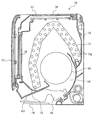
- FIG. 2 is a longitudinal sectional view of the indoor unit 10.
- the indoor unit 10 includes the indoor heat exchanger 12, the drain pan 13, the indoor fan 14, the housing base 15, the filters 16, 16 and the front panel in addition to the remote control transmission / reception unit 11 (see FIG. 1) described above.
- a left and right wind direction plate 18 and a vertical wind direction plate 19 are provided.
- the indoor heat exchanger 12 is a heat exchanger in which heat exchange is performed between the refrigerant flowing through the heat transfer tube 12g and the indoor air.
- the drain pan 13 receives water dripping from the indoor heat exchanger 12 and is disposed below the indoor heat exchanger 12. The water dripping on the drain pan 13 is drained to the outside through a drain hose (not shown).
- the indoor fan 14 is, for example, a cylindrical cross flow fan, and is driven by an indoor fan motor 14a (see FIG. 4).
- the housing base 15 is a housing in which devices such as the indoor heat exchanger 12 and the indoor fan 14 are installed.
- the filters 16, 16 are for removing dust from the air taken in through the air inlet h1 etc., and are installed on the upper side and the front side of the indoor heat exchanger 12.
- the front panel 17 is a panel installed so as to cover the filter 16 on the front side, and can be pivoted to the front side with the lower end as an axis. The front panel 17 may not be rotated.
- the left and right wind direction plate 18 is a plate-like member that adjusts the wind direction of the air blown out into the room in the left and right direction.
- the left and right wind direction plate 18 is disposed on the downstream side of the indoor fan 14 and rotated in the left and right direction by the left and right wind direction plate motor 21 (see FIG. 4).
- the vertical wind direction plate 19 is a plate-like member that adjusts the wind direction of the air blown out into the room in the vertical direction.
- the vertical wind direction plate 19 is disposed on the downstream side of the indoor fan 14, and is configured to rotate in the vertical direction by the vertical wind direction plate motor 22 (see FIG. 4).
- the air sucked in through the air suction port h1 exchanges heat with the refrigerant flowing through the heat transfer pipe 12g, and the heat-exchanged air is guided to the blowoff air path h2.
- the air flowing through the blowout air path h2 is guided in a predetermined direction by the left and right wind direction plates 18 and the up and down wind direction plates 19 and is further blown out into the room through the air outlet h3.
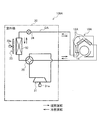
- FIG. 3 is an explanatory view showing the refrigerant circuit Q of the air conditioner 100.
- the solid line arrow of FIG. 3 has shown the flow of the refrigerant
- the broken line arrow in FIG. 3 indicates the flow of the refrigerant during the cooling operation.
- the indoor unit 10 shown in FIG. 3 includes an indoor expansion valve V (second expansion valve) in addition to the above-described configuration.
- the indoor heat exchanger 12 includes a first indoor heat exchanger 12a and a second indoor heat exchanger 12b. The first indoor heat exchanger 12a and the second indoor heat exchanger 12b are connected to each other via the indoor expansion valve V.
- the first indoor heat exchanger 12 a is located above the second indoor heat exchanger 12 b. That is, the first indoor heat exchanger 12 a is an upper portion of the indoor heat exchanger 12.
- the second indoor heat exchanger 12 b is a lower part of the indoor heat exchanger 12.
- the outdoor unit 30 includes a compressor 31, an outdoor heat exchanger 32, an outdoor fan 33, an outdoor expansion valve 34 (first expansion valve), and a four-way valve 35. .
- the compressor 31 is a device that compresses a low-temperature low-pressure gas refrigerant and discharges it as a high-temperature high-pressure gas refrigerant by driving the compressor motor 31 a.
- the outdoor heat exchanger 32 is a heat exchanger in which heat exchange is performed between the refrigerant flowing through the heat transfer pipe (not shown) and the outside air fed from the outdoor fan 33.
- the outdoor fan 33 is a fan that sends outside air to the outdoor heat exchanger 32 by driving of the outdoor fan motor 33 a, and is installed near the outdoor heat exchanger 32.
- the outdoor expansion valve 34 has a function of decompressing the refrigerant, and is provided in the refrigerant pipe J connecting the outdoor heat exchanger 32 and the second indoor heat exchanger 12 b.
- the four-way valve 35 is a valve that switches the flow path of the refrigerant according to the operation mode of the air conditioner 100. For example, during the cooling operation (refer to the broken line arrow), the compressor 31, the outdoor heat exchanger 32 (condenser), the outdoor expansion valve 34, the second indoor heat exchanger 12b (evaporator) The refrigerant circulates in the refrigeration cycle sequentially through the fully-opened indoor expansion valve V and the first indoor heat exchanger 12a (evaporator).
- the compressor 31 In the heating operation (see solid arrows), in the refrigerant circuit Q, the compressor 31, the first indoor heat exchanger 12a (condenser), the indoor expansion valve V in a substantially fully opened state, and the second indoor heat exchanger 12b.
- the refrigerant circulates in the refrigeration cycle via the (condenser), the outdoor expansion valve 34, and the outdoor heat exchanger 32 (evaporator) sequentially.
- the indoor expansion valve V is throttled appropriately.
- FIG. 4 is a functional block diagram of the air conditioner 100.
- the indoor unit 10 shown in FIG. 4 includes an imaging unit 23, an environment detection unit 24, and an indoor control circuit 25 in addition to the above-described configuration.
- the imaging unit 23 images a room, and includes an imaging element such as a CCD sensor (charge coupled device) or a CMOS sensor (complementary metal oxide semiconductor).
- the indoor control circuit 25 Based on the imaging result of the imaging unit 23, the indoor control circuit 25 detects a person present in the room.
- the “person detection unit” that detects a person present in the room (air conditioned space) includes an imaging unit 23 and an indoor control circuit 25.
- the environment detection unit 24 has a function of detecting the indoor condition or the device condition of the indoor unit 10. As shown in FIG. 4, the environment detection unit 24 includes an indoor temperature sensor 24a, a humidity sensor 24b, and an indoor heat exchanger temperature sensor 24c.
- the indoor temperature sensor 24a is a sensor that detects the temperature in the room, and is installed at a predetermined position of the indoor unit 10 (for example, the air suction side of the filters 16, 16 shown in FIG. 2).
- the humidity sensor 24 b is a sensor that detects the humidity of the air in the room, and is installed at a predetermined position of the indoor unit 10.
- the indoor heat exchanger temperature sensor 24 c is a sensor that detects the temperature of the indoor heat exchanger 12 (see FIG. 2), and is installed in the indoor heat exchanger 12. Detection values of the indoor temperature sensor 24 a, the humidity sensor 24 b, and the indoor heat exchanger temperature sensor 24 c are output to the indoor control circuit 25.
- the indoor control circuit 25 includes electronic circuits such as a central processing unit (CPU), a read only memory (ROM), a random access memory (RAM), and various interfaces. Then, the program stored in the ROM is read and expanded in the RAM, and the CPU executes various processing.
- CPU central processing unit
- ROM read only memory
- RAM random access memory
- the indoor control circuit 25 includes a storage unit 25 a and an indoor control unit 25 b.
- the storage unit 25a stores, in addition to a predetermined program, an imaging result of the imaging unit 23, a detection result of the environment detection unit 24, data received via the remote control transmission / reception unit 11, and the like.
- the indoor control unit 25b executes predetermined control based on the data stored in the storage unit 25a. The processing executed by the indoor control unit 25b will be described later.
- the outdoor unit 30 includes an outdoor temperature sensor 36 and an outdoor control circuit 37 in addition to the above-described configuration.
- the outdoor temperature sensor 36 is a sensor that detects an outdoor temperature (outside temperature), and is installed at a predetermined location of the outdoor unit 30.
- the outdoor unit 30 also includes sensors that detect the suction temperature, the discharge temperature, the discharge pressure, and the like of the compressor 31 (see FIG. 3). The detection value of each sensor including the outdoor temperature sensor 36 is output to the outdoor control circuit 37.
- the outdoor control circuit 37 includes electronic circuits such as a CPU, a ROM, a RAM, and various interfaces, and is connected to the indoor control circuit 25 via a communication line. As shown in FIG. 4, the outdoor control circuit 37 includes a storage unit 37 a and an outdoor control unit 37 b.
- the storage unit 37a stores, in addition to a predetermined program, detection values and the like of each sensor including the outdoor temperature sensor 36.
- the outdoor control unit 37b controls the compressor motor 31a, the outdoor fan motor 33a, the outdoor expansion valve 34, and the like based on the data stored in the storage unit 37a.
- control unit K the indoor control circuit 25 and the outdoor control circuit 37 will be collectively referred to as "control unit K".
- the filters 16 and 16 for collecting dust and dirt are disposed on the upper side and the front side (air suction side) of the indoor heat exchanger 12.
- fine dust and dirt, as well as oil associated with cooking and the like may pass through the filter 16 and adhere to the indoor heat exchanger 12. Therefore, it is desirable to periodically clean the indoor heat exchanger 12. Therefore, in the present embodiment, the water contained in the air in the indoor unit 10 is frozen by the indoor heat exchanger 12, and then the ice and frost of the indoor heat exchanger 12 are melted to clean the indoor heat exchanger 12. I am trying to do it.
- cleaning process Such a series of processes is referred to as "cleaning process" of the indoor heat exchanger 12.
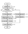
- FIG. 5 is a flowchart of the cleaning process performed by the control unit K of the air conditioner 100 (see FIGS. 3 and 4 as appropriate). It is assumed that a predetermined air conditioning operation (cooling operation, heating operation, etc.) has been performed until "START" in FIG. Further, it is assumed that the start condition of the cleaning process of the indoor heat exchanger 12 is satisfied at the time of "START".
- the “cleaning process start condition” is, for example, a condition that a value obtained by integrating the air conditioning operation execution time from the end of the previous cleaning process has reached a predetermined value.
- step S101 the control unit K stops the air conditioning operation for a predetermined time (for example, several minutes).
- the aforementioned predetermined time is a time for stabilizing the refrigeration cycle, and is set in advance. For example, when freezing the indoor heat exchanger 12 by interrupting the heating operation which has been performed until "START" (S103), the control unit K causes the refrigerant to flow in the opposite direction to that during the heating operation.
- the valve 35 is controlled.
- step S101 may be omitted. This is because the direction in which the refrigerant flows during the cooling operation (immediately before START) is the same as the direction in which the refrigerant flows during freezing of the indoor heat exchanger 12 (S103).
- step S102 the control unit K determines whether or not a kitchen is present in the air conditioned space. That is, whether the control unit K has a kitchen in the air-conditioned space based on the change in the position of the person detected by the above-mentioned "person detection unit” (the imaging unit 23 and the indoor control unit 25b: see FIG. 4) It is determined whether or not.
- step S102 the control unit K detects a person present in the air-conditioned space based on the imaging result of the imaging unit 23.
- the height of the head of the person detected by the above-mentioned “person detection unit” is within the predetermined range, and the control unit K is in the horizontal direction or depth direction when the person is viewed from the indoor unit 10 (
- the control unit K When reciprocating within a predetermined distance, it is determined that the person is cooking in the kitchen (that is, there is a kitchen in the conditioned space).
- a person is cooking in the kitchen, it often reciprocates in the lateral direction or the depth direction with the person standing.
- step S102 When a kitchen exists in the air conditioned space at step S102 (S102: Yes), the process of the control unit K proceeds to step S103. In this case, there is a high possibility that the oil generated with cooking in the kitchen adheres to the indoor heat exchanger 12.
- step S103 the control unit K freezes the indoor heat exchanger 12. That is, the control unit K freezes the first indoor heat exchanger 12a and the second indoor heat exchanger 12b shown in FIG. Specifically describing step S103, the control unit K causes the first indoor heat exchanger 12a and the second indoor heat exchanger 12b to function as an evaporator, as in the cooling operation. In this case, the indoor expansion valve V is in a substantially fully opened state, and the opening degree of the outdoor expansion valve 34 is appropriately adjusted. As a result, the water contained in the air in the indoor unit 10 frosts on the first indoor heat exchanger 12a and the second indoor heat exchanger 12b and freezes. The details of the process of step S103 will be described later.
- step S104 the control unit K performs the above-described reheat dehumidification to thaw the upper portion of the indoor heat exchanger 12. That is, the control unit K causes the first indoor heat exchanger 12a to function as a condenser, and causes the second indoor heat exchanger 12b to function as an evaporator.
- the outdoor expansion valve 34 is substantially fully open, and the degree of opening of the indoor expansion valve V is appropriately adjusted.
- the first indoor heat exchanger 12a upper part of the indoor heat exchanger 12
- the freezing of the second indoor heat exchanger 12 b (the lower part of the indoor heat exchanger 12) further proceeds.
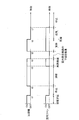
- FIG. 6 is an explanatory view showing a driving state of the compressor 31 and the indoor fan 14 when there is a kitchen in the air conditioned space (refer to FIG. 3 as appropriate).
- the horizontal axis in FIG. 6 is time. Further, the vertical axis in FIG. 6 indicates ON / OFF of the compressor 31 and ON / OFF of the indoor fan 14.
- the predetermined air conditioning operation is performed until time t1, and the compressor 31 and the indoor fan 14 are driven (that is, in the ON state). Thereafter, the compressor 31 and the indoor fan 14 stop at time t1 to t2 (S101 in FIG. 5). Then, the indoor heat exchanger 12 is frozen at time t2 to t3 (S103), and reheat dehumidification is performed at time t3 to t4 (S104).
- the water vapor pressure in the indoor unit 10 is lowered by freezing the water vapor in the indoor heat exchanger 12, and the water vapor diffusion phenomenon etc. (natural convection) As a result, the water vapor continues to be supplied to the surface of the indoor heat exchanger 12 and the frost grows.
- the refrigerant flows in the same direction as at the time of the cooling operation, and at the time of reheat dehumidification (S104), the refrigerant in the same direction as the heating operation. Flows. That is, the flow direction of the refrigerant is opposite between the time of freezing of the indoor heat exchanger 12 and the time of reheat dehumidification.
- reheat dehumidification is started immediately after freezing of the indoor heat exchanger 12 is finished (without providing a predetermined stop period) (see time t3 in FIG. 6).
- the control unit K starts thawing of the first indoor heat exchanger 12a immediately after the freezing of the first indoor heat exchanger 12a and the second indoor heat exchanger 12b is finished.
- reheat dehumidification (time t3 to t4) can be performed without melting the frost adhering to the second indoor heat exchanger 12b. If reheating dehumidification is started after the frost in the second indoor heat exchanger 12b is completely melted, dirt such as dust, dirt, or oil adhering to the first indoor heat exchanger 12a mixes with water and flows off. , And the surface of the second indoor heat exchanger 12b is soiled. Therefore, in the present embodiment, the stop period of each device is not intentionally provided between the freezing operation (time t2 to t3) and the reheat dehumidification (time t3 to t4).
- step S105 the control unit K thaws the lower portion of the indoor heat exchanger 12. That is, the control unit K thaws the second indoor heat exchanger 12b.
- the control unit K keeps the stopped state of the device including the compressor 31, the outdoor fan 33, and the indoor fan 14 shown in FIG. 3 for a predetermined time.
- the ice and frost of the second indoor heat exchanger 12b melt naturally at room temperature.
- the layer of ice formed in the second indoor heat exchanger 12b by the processing of step S104 prior to this including dirt such as dust, dirt, oil, etc. adhering to the first indoor heat exchanger 12a
- the ice layer melts at room temperature and drips into drain pan 13 (see FIG. 2).
- the frost adhering to the second indoor heat exchanger 12 b by the process of step 103 exists inside the ice layer. That is, water containing dirt such as dust, dirt or oil adhering to the first indoor heat exchanger 12a flows down directly along the surface of the fin (not shown) of the second indoor heat exchanger 12b. Rather, it flows down the outside of the frost attached to this fin. Therefore, the second indoor heat exchanger 12b is hardly contaminated by dust, dirt, oil or the like adhering to the first indoor heat exchanger 12a.
- the frost on the inner side of the ice layer melts and drips into the drain pan 13 (see FIG. 2).
- the second indoor heat exchanger 12b is also cleaned.
- the water dripping on the drain pan 13 is drained to the outside through a drain hose (not shown).
- the control unit K freezes the indoor heat exchanger 12 (S103), thaws the upper portion of the indoor heat exchanger 12 (S104), and The lower part (S105) of the indoor heat exchanger 12 is sequentially performed.
- step S106 the control unit K dries the indoor heat exchanger 12.
- the control unit K sequentially performs the heating operation and the blowing operation as the process of step S106. Since the high temperature refrigerant flows to the indoor heat exchanger 12 by the heating operation described above, the water on the surface of the indoor heat exchanger 12 evaporates. Furthermore, since the inside of the indoor unit 10 is dried by the air blowing operation after the heating operation, the effects of microbes and defenses are exerted.
- the control unit K ends the series of cleaning processes (END).
- step S103 and S104 in FIG. 5 after freezing and reheat dehumidification are sequentially performed at time t2 to t4 (steps S103 and S104 in FIG. 5), the lower portion of the indoor heat exchanger 12 is thawed at time t4 to t5. (S105). Thereafter, the heating operation and the blowing operation are sequentially performed at time t5 to t7, whereby the indoor heat exchanger 12 is dried (S106).
- step S102 of FIG. 5 when it determines with a kitchen not existing in to-be-conditioned space (S102: No), a process of control part K progresses to step S107. In this case, the possibility of oil adhering to the indoor heat exchanger 12 is low. Therefore, after freezing the indoor heat exchanger 12 in step S107, the control unit K proceeds to the process of step S108 without performing the above-described reheat dehumidification.
- step S108 the control unit K thaws the indoor heat exchanger 12. That is, the control unit K thaws both the first indoor heat exchanger 12a and the second indoor heat exchanger 12b.
- the control unit K keeps the stopped state of the device including the compressor 31, the outdoor fan 33, and the indoor fan 14 shown in FIG. 3 for a predetermined time.
- the frost of the indoor heat exchanger 12 melts naturally at room temperature, dust and dirt adhering to the indoor heat exchanger 12 are washed away.
- a kitchen does not exist in air-conditioned space (S102: No)
- control unit K After performing the process of step S108, the control unit K dries the indoor heat exchanger 12 in step S106, and ends the series of cleaning processes (END).
- FIG. 7 is a flowchart showing a process (S103 in FIG. 5) for freezing the indoor heat exchanger 12 (see FIGS. 3 and 4 as appropriate).
- the control unit K controls the four-way valve 35. That is, the control unit K controls the four-way valve 35 such that the outdoor heat exchanger 32 functions as a condenser and the indoor heat exchanger 12 functions as an evaporator.
- the control device maintains the state of the four-way valve 35 in step S103a. .
- step S103 b the control unit K sets a freezing time.
- the “freezing time” is a time during which predetermined control (S103c to S103e) for freezing the indoor heat exchanger 12 is continued.
- the control unit K sets the freezing time to be shorter as the detection value of the humidity sensor 24b (see FIG. 4) is higher.
- the indoor heat exchanger 12 can be frosted with an appropriate amount of water required for cleaning the indoor heat exchanger 12.
- the freezing time of the indoor heat exchanger 12 may be a fixed value.
- step S103 c the control unit K sets the rotational speed of the compressor 31.
- the control unit K increases the rotational speed of the compressor motor 31a as the detection value of the outdoor temperature sensor 36 (see FIG. 4) is higher. This is because in order to remove heat from indoor air in the indoor heat exchanger 12, it is necessary that heat dissipation in the outdoor heat exchanger 32 be sufficiently performed correspondingly.
- the rotational speed of the compressor 31 By setting the rotational speed of the compressor 31 in this manner, heat exchange in the outdoor heat exchanger 32 is appropriately performed, and in turn, freezing of the indoor heat exchanger 12 is also appropriately performed.
- step S103 d the control unit K adjusts the opening degree of the outdoor expansion valve 34.
- step S103d it is desirable to make the opening degree of the outdoor expansion valve 34 smaller than that during normal cooling operation.
- a refrigerant having a lower temperature and a lower pressure than in the normal cooling operation flows into the indoor heat exchanger 12 via the outdoor expansion valve 34. Therefore, the indoor heat exchanger 12 is easily frozen, and the amount of power consumption required for freezing the indoor heat exchanger 12 can be reduced.
- step S103e the control unit K determines whether the temperature of the indoor heat exchanger 12 is within a predetermined range.
- the above-mentioned "predetermined range” is a range in which the moisture contained in the air in the indoor unit 10 can be frozen by the indoor heat exchanger 12, and is set in advance.
- the temperature of the indoor heat exchanger 12 is detected by an indoor heat exchanger temperature sensor 24c (see FIG. 4).
- step S103e When the temperature of the indoor heat exchanger 12 is out of the predetermined range in step S103e (S103e: No), the process of the control unit K returns to step S103d. For example, when the temperature of the indoor heat exchanger 12 is higher than the predetermined range, the control unit K further reduces the opening degree of the outdoor expansion valve 34 (S103 d). Thus, when freezing the indoor heat exchanger 12, the controller K adjusts the degree of opening of the outdoor expansion valve 34 so that the temperature of the indoor heat exchanger 12 falls within the predetermined range.
- the control unit K may stop the indoor fan 14 (see times t2 to t3 in FIG. 6), or the indoor fan 14 may be stopped. It may be driven at a rotational speed. In either case, the freezing of the indoor heat exchanger 12 proceeds. Further, while the indoor heat exchanger 12 is freezing, the vertical wind direction plate 19 (see FIG. 2) may be either open or closed, but the closed state gives less discomfort to the user.
- step S103f the control unit K determines whether the freezing time set in step S103 b has elapsed.
- the predetermined freezing time has not elapsed from the time of “START” (S103 f: No)
- the process of the control unit K returns to step S103 c.
- the control unit K ends the series of processes for freezing the indoor heat exchanger 12 (END).
- step S103 a series of processes shown in FIG. 7 about the process (freezing of the indoor heat exchanger 12) of step S107 shown in FIG. 5, detailed description is abbreviate
- the control unit K freezes the indoor heat exchanger 12 (S103), and first performs indoor heat exchange.
- the upper part of vessel 12 is thawed (S104).
- dirt such as dust, dirt, oil and the like adhering to the upper part of the indoor heat exchanger 12 flows down and is frozen at the lower part of the indoor heat exchanger 12 in a frozen state to form an ice layer.
- the second embodiment is different from the first embodiment in that the indoor expansion valve is not provided in the indoor unit 10A (see FIG. 8).
- the rotational speed of the compressor 31 (see FIG. 8) is made smaller than that during normal air conditioning operation to thaw the upper portion of the indoor heat exchanger 12A (see FIG. 8). It differs from the two embodiments.
- the rest (the configuration shown in FIG. 1, FIG. 2, FIG. 4, the flowchart shown in FIG. 7, etc.) is the same as that of the first embodiment. Therefore, only the parts different from the first embodiment will be described, and the descriptions of the overlapping parts will be omitted.
- FIG. 8 is an explanatory view showing a refrigerant circuit QA of the air conditioner 100A according to the second embodiment.
- the refrigerant circuit QA shown in FIG. 8 is a circuit in which the refrigerant circulates in the refrigeration cycle sequentially through the compressor 31, the "condenser", the outdoor expansion valve 34 (first expansion valve), and the "evaporator”. .
- One of the "condenser” and the “evaporator” is the outdoor heat exchanger 32, and the other is at least a part of the indoor heat exchanger 12A.
- the indoor heat exchanger 12A When the indoor heat exchanger 12A is made to function as an evaporator (see the broken arrow in FIG. 8), the upper portion of the indoor heat exchanger 12A is located downstream of the lower portion of the indoor heat exchanger 12A. There is.
- FIG. 9 is a flowchart of the cleaning process performed by the control unit K of the air conditioner 100 (see FIG. 8 as appropriate). In addition, the same step number is attached
- step S104a the control unit K reduces the rotational speed of the compressor 31 (that is, the rotational speed of the compressor motor 31a shown in FIG. 4) than in the normal air conditioning operation to thaw the upper portion of the indoor heat exchanger 12A. Do. The process of step S104a will be described in detail.
- the control unit K controls the four-way valve 35 so that the refrigerant flows in the same direction as in the cooling operation, and drives the compressor 31.
- the compressor 31, the outdoor heat exchanger 32, the outdoor expansion valve 34, the upper portion of the indoor heat exchanger 12A, and the lower portion of the indoor heat exchanger 12A are sequentially
- the refrigerant circulates in the refrigerant circuit QA.
- the flow rate of the refrigerant flowing through the indoor heat exchanger 12A is greater than that during normal air conditioning operation (for example, during cooling operation) It becomes smaller.
- the refrigerant evaporates in the middle of the flow path of the indoor heat exchanger 12A, so that the upstream side freezes and the downstream side is thawed. In other words, freezing proceeds in the lower part of the indoor heat exchanger 12A, and the upper part of the indoor heat exchanger 12A is thawed.
- steps S105 to S108 are the same as in the first embodiment (see FIG. 5), and thus the description thereof is omitted.
- the flow of the refrigerant in the refrigerant circuit QA is the cooling operation time It is similar. Therefore, immediately after the start of thawing of the upper portion of the indoor heat exchanger 12A, for example, the temperature of the refrigerant does not rapidly change in the indoor heat exchanger 12A, nor does the direction of the refrigerant flow suddenly change. It is possible to suppress the generation of sound accompanying these phenomena.
- the above-mentioned "predetermined time” is preset as a time of the extent which the 2nd indoor heat exchanger 12b does not fully defrost.
- each device including the compressor 31 is stopped.
- the first indoor heat exchanger 12a can be thawed while the second indoor heat exchanger 12b remains frozen.
- the flow of the refrigerant changes in the opposite direction (a flow similar to the cooling operation at the time of freezing, a flow similar to the heating operation at the thawing of the first indoor heat exchanger 12 a) It is possible to suppress the generation of accompanying sound.
- control part K demonstrated the process (S105 of FIG. 5) which decompress
- the control unit K may cause the lower part of the indoor heat exchanger 12 to be thawed by causing the indoor heat exchanger 12 to function as a condenser.
- the lower part of the indoor heat exchanger 12 may be thawed by the control unit K performing the blowing operation.
- control unit K may dry the indoor heat exchanger 12 by performing only the heating operation for a predetermined time.
- control unit K may dry the indoor heat exchanger 12 by performing only the blowing operation for a predetermined time.
- the control part K demonstrates the process (S102 of FIG. 5) which determines whether a kitchen exists in air-conditioned space based on the imaging result of the imaging part 23 (refer FIG. 4).
- a thermal image of the room may be acquired by an indoor temperature sensor 24a (a human detection unit: see FIG. 4) such as a thermopile or a pyroelectric infrared sensor.
- the control unit K detects a change in the position of a person based on the above-described thermal image, and determines whether or not a kitchen is present in the air-conditioned space.
- the control unit K decompresses the upper part and the lower part of the indoor heat exchanger 12 stepwise (S104) , S105), but it is not limited thereto.
- the upper and lower portions of the indoor heat exchanger 12 may be thawed stepwise, regardless of the presence of a kitchen in the air conditioned space.
- dirt such as dust, dirt, oil and the like adhering to the indoor heat exchanger 12 can be properly washed away.
- the control unit K sets the rotational speed of the compressor 31 and appropriately adjusts the opening degree of the outdoor expansion valve 34 (FIG. 7).
- S103c and S103d) have been described, but the present invention is not limited thereto.
- the control unit K maintains the outdoor expansion valve 34 at a predetermined opening degree, and the compressor 31 such that the temperature of the indoor heat exchanger 12 approaches a predetermined target temperature.
- the rotational speed of the lens may be adjusted.
- the entire indoor heat exchanger 12 is frozen, the first indoor heat exchanger 12a (the upper portion of the indoor heat exchanger 12) is thawed, and the second indoor heat exchanger 12b (room heat exchange).
- reheat dehumidification may be performed to freeze the second indoor heat exchanger 12b.
- the control unit in the refrigerant circuit Q in which the refrigerant circulates in the refrigeration cycle via the compressor 31, the "condenser", the second expansion valve V, and the "evaporator” sequentially K may perform reheat dehumidification as follows.
- the control unit K causes the first indoor heat exchanger 12a upstream of the second expansion valve V to function as a condenser, and evaporates the second indoor heat exchanger 12b downstream of the second expansion valve V.
- the second indoor heat exchanger 12b is frozen by functioning as a container.
- the entire indoor heat exchanger 12 may be frozen (similar to S103 in FIG. 5), or the cleaning effect of the indoor heat exchanger 12 can be exhibited without freezing.
- the dew condensation water associated with the cooling operation or the like flows down through the indoor heat exchanger 12b, so the lower portion (the second indoor heat exchanger 12b) of the indoor heat exchanger 12 is easily contaminated.
- the water accompanying the thawing flows down with the dirt attached to the second heat exchanger 12b, so that the indoor heat exchanger 12 can be effectively cleaned.
- the first embodiment and the second embodiment may be combined.
- the indoor expansion valve V (see FIG. 3) is substantially fully opened, and the series of cleaning processes described in the second embodiment (see FIG. 9) May be performed.
- the control unit K may appropriately perform reheat dehumidification in accordance with the operation of the remote control 40 (see FIG. 1) by the user, separately from the series of cleaning processes described above.
- each embodiment demonstrated the structure in which the indoor unit 10 and the outdoor unit 30 are provided 1 each, it does not restrict to this. That is, a plurality of indoor units connected in parallel may be provided, or a plurality of outdoor units connected in parallel may be provided.
Abstract
室内熱交換器を適切に洗浄可能な空気調和機を提供する。空気調和機(100)は、圧縮機(31)、凝縮器、室外膨張弁(34)、及び蒸発器を順次に介して、冷凍サイクルで冷媒が循環する冷媒回路(Q)と、少なくとも圧縮機(31)及び室外膨張弁(34)を制御する制御部と、を備える。前記した凝縮器及び蒸発器の一方は室外熱交換器(32)であり、他方は室内熱交換器(12)の少なくとも一部である。制御部は、室内熱交換器(12)の凍結、室内熱交換器(12)の上部の解凍、及び、室内熱交換器(12)の下部の解凍を順次に行う。
Description
本発明は、空気調和機に関する。
空気調和機の室内熱交換器を清潔な状態にする技術として、例えば、特許文献1には、「暖房運転後に、前記フィン表面に水を付着させる水分付与手段を備える」空気調和機について記載されている。なお、前記した水分付与手段は、暖房運転後に冷房運転を行うことによって、室内熱交換器のフィン表面に水を付着させる。
しかしながら、特許文献1に記載の技術では、室内熱交換器のフィン表面に付着した水が滴り落ちると、場合によっては、室内熱交換器の下部に汚れが残る可能性がある。
そこで、本発明は、室内熱交換器を適切に洗浄可能な空気調和機を提供することを課題とする。
前記課題を解決するために、本発明は、制御部が、室内熱交換器の凍結、前記室内熱交換器の上部の解凍、及び、前記室内熱交換器の下部の解凍を順次に行うことを特徴とする。
また、本発明は、室内熱交換器の上部である第1室内熱交換器と、前記室内熱交換器の下部である第2室内熱交換器と、が第2膨張弁を介して接続され、制御部が、前記第2膨張弁の上流側である前記第1室内熱交換器を凝縮器として機能させ、前記第2膨張弁の下流側である前記第2室内熱交換器を蒸発器として機能させて、当該第2室内熱交換器を凍結させることを特徴とする。
本発明によれば、室内熱交換器を適切に洗浄可能な空気調和機を提供できる。
≪第1実施形態≫
<空気調和機の構成>
図1は、第1実施形態に係る空気調和機100が備える室内機10、室外機30、及びリモコン40の正面図である。
空気調和機100は、冷凍サイクル(ヒートポンプサイクル)で冷媒を循環させることによって、空調を行う機器である。空気調和機100は、室内(被空調空間)に設置される室内機10と、屋外に設置される室外機30と、ユーザによって操作されるリモコン40と、を備えている。
<空気調和機の構成>
図1は、第1実施形態に係る空気調和機100が備える室内機10、室外機30、及びリモコン40の正面図である。
空気調和機100は、冷凍サイクル(ヒートポンプサイクル)で冷媒を循環させることによって、空調を行う機器である。空気調和機100は、室内(被空調空間)に設置される室内機10と、屋外に設置される室外機30と、ユーザによって操作されるリモコン40と、を備えている。
図1に示すように、室内機10は、リモコン送受信部11を備えている。リモコン送受信部11は、赤外線通信等によって、リモコン40との間で所定の信号を送受信する。例えば、リモコン送受信部11は、運転/停止指令、設定温度の変更、運転モードの変更、タイマの設定等の信号をリモコン40から受信する。また、リモコン送受信部11は、室内温度の検出値等をリモコン40に送信する。
なお、図1では省略しているが、室内機10と室外機30とは冷媒配管を介して接続されるとともに、通信線を介して接続されている。
図2は、室内機10の縦断面図である。
室内機10は、前記したリモコン送受信部11(図1参照)の他に、室内熱交換器12と、ドレンパン13と、室内ファン14と、筐体ベース15と、フィルタ16,16と、前面パネル17と、左右風向板18と、上下風向板19と、を備えている。
室内機10は、前記したリモコン送受信部11(図1参照)の他に、室内熱交換器12と、ドレンパン13と、室内ファン14と、筐体ベース15と、フィルタ16,16と、前面パネル17と、左右風向板18と、上下風向板19と、を備えている。
室内熱交換器12は、その伝熱管12gを通流する冷媒と、室内空気と、の間で熱交換が行われる熱交換器である。
ドレンパン13は、室内熱交換器12から滴り落ちる水を受けるものであり、室内熱交換器12の下側に配置されている。なお、ドレンパン13に滴り落ちた水は、ドレンホース(図示せず)を介して外部に排出される。
ドレンパン13は、室内熱交換器12から滴り落ちる水を受けるものであり、室内熱交換器12の下側に配置されている。なお、ドレンパン13に滴り落ちた水は、ドレンホース(図示せず)を介して外部に排出される。
室内ファン14は、例えば、円筒状のクロスフローファンであり、室内ファンモータ14a(図4参照)によって駆動する。
筐体ベース15は、室内熱交換器12や室内ファン14等の機器が設置される筐体である。
筐体ベース15は、室内熱交換器12や室内ファン14等の機器が設置される筐体である。
フィルタ16,16は、空気吸込口h1等を介して取り込まれる空気から塵埃を除去するものであり、室内熱交換器12の上側・前側に設置されている。
前面パネル17は、前側のフィルタ16を覆うように設置されるパネルであり、下端を軸として前側に回動可能になっている。なお、前面パネル17が回動しない構成であってもよい。
前面パネル17は、前側のフィルタ16を覆うように設置されるパネルであり、下端を軸として前側に回動可能になっている。なお、前面パネル17が回動しない構成であってもよい。
左右風向板18は、室内に吹き出される空気の風向きを、左右方向において調整する板状部材である。左右風向板18は、室内ファン14の下流側に配置され、左右風向板用モータ21(図4参照)によって左右方向に回動するようになっている。
上下風向板19は、室内に吹き出される空気の風向きを、上下方向において調整する板状部材である。上下風向板19は、室内ファン14の下流側に配置され、上下風向板用モータ22(図4参照)によって上下方向に回動するようになっている。
上下風向板19は、室内に吹き出される空気の風向きを、上下方向において調整する板状部材である。上下風向板19は、室内ファン14の下流側に配置され、上下風向板用モータ22(図4参照)によって上下方向に回動するようになっている。
空気吸込口h1を介して吸い込まれた空気は、伝熱管12gを通流する冷媒と熱交換し、熱交換した空気が吹出風路h2に導かれる。この吹出風路h2を通流する空気は、左右風向板18及び上下風向板19によって所定方向に導かれ、さらに、空気吹出口h3を介して室内に吹き出される。
図3は、空気調和機100の冷媒回路Qを示す説明図である。
なお、図3の実線矢印は、暖房運転時又は再熱除湿時の冷媒の流れを示している。
また、図3の破線矢印は、冷房運転時の冷媒の流れを示している。
図3に示す室内機10は、前記した構成の他に、室内膨張弁V(第2膨張弁)を備えている。また、室内熱交換器12は、第1室内熱交換器12aと、第2室内熱交換器12bと、を備えている。そして、第1室内熱交換器12a及び第2室内熱交換器12bが、室内膨張弁Vを介して相互に接続されている。
なお、図3の実線矢印は、暖房運転時又は再熱除湿時の冷媒の流れを示している。
また、図3の破線矢印は、冷房運転時の冷媒の流れを示している。
図3に示す室内機10は、前記した構成の他に、室内膨張弁V(第2膨張弁)を備えている。また、室内熱交換器12は、第1室内熱交換器12aと、第2室内熱交換器12bと、を備えている。そして、第1室内熱交換器12a及び第2室内熱交換器12bが、室内膨張弁Vを介して相互に接続されている。
図3に示すように、第1室内熱交換器12aは、第2室内熱交換器12bの上側に位置している。つまり、第1室内熱交換器12aは、室内熱交換器12の上部である。また、第2室内熱交換器12bは、室内熱交換器12の下部である。
図3に示すように、室外機30は、圧縮機31と、室外熱交換器32と、室外ファン33と、室外膨張弁34(第1膨張弁)と、四方弁35と、を備えている。
圧縮機31は、圧縮機モータ31aの駆動によって、低温低圧のガス冷媒を圧縮し、高温高圧のガス冷媒として吐出する機器である。
室外熱交換器32は、その伝熱管(図示せず)を通流する冷媒と、室外ファン33から送り込まれる外気と、の間で熱交換が行われる熱交換器である。
室外熱交換器32は、その伝熱管(図示せず)を通流する冷媒と、室外ファン33から送り込まれる外気と、の間で熱交換が行われる熱交換器である。
室外ファン33は、室外ファンモータ33aの駆動によって、室外熱交換器32に外気を送り込むファンであり、室外熱交換器32の付近に設置されている。
室外膨張弁34は、冷媒を減圧する機能を有し、室外熱交換器32と第2室内熱交換器12bとを接続する冷媒配管Jに設けられている。
室外膨張弁34は、冷媒を減圧する機能を有し、室外熱交換器32と第2室内熱交換器12bとを接続する冷媒配管Jに設けられている。
四方弁35は、空気調和機100の運転モードに応じて、冷媒の流路を切り替える弁である。例えば、冷房運転時(破線矢印を参照)には、冷媒回路Qにおいて圧縮機31、室外熱交換器32(凝縮器)、室外膨張弁34、第2室内熱交換器12b(蒸発器)、略全開状態の室内膨張弁V、及び第1室内熱交換器12a(蒸発器)を順次に介して、冷凍サイクルで冷媒が循環する。
また、暖房運転時(実線矢印を参照)には、冷媒回路Qにおいて圧縮機31、第1室内熱交換器12a(凝縮器)、略全開状態の室内膨張弁V、第2室内熱交換器12b(凝縮器)、室外膨張弁34、及び室外熱交換器32(蒸発器)を順次に介して、冷凍サイクルで冷媒が循環する。
また、いわゆる再熱除湿時(実線矢印を参照)には、冷媒回路Qにおいて圧縮機31、第1室内熱交換器12a(凝縮器)、室内膨張弁V、第2室内熱交換器12b(蒸発器)、略全開状態の室外膨張弁34、及び室外熱交換器32(蒸発器)を順次に介して、冷凍サイクルで冷媒が循環する。なお、再熱除湿時には、室内膨張弁Vが適宜に絞られる。
図4は、空気調和機100の機能ブロック図である。
図4に示す室内機10は、前記した構成の他に、撮像部23と、環境検出部24と、室内制御回路25と、を備えている。
撮像部23は、室内を撮像するものであり、CCDセンサ(Charge Coupled Device)やCMOSセンサ(Complementary Metal Oxide Semiconductor)等の撮像素子を備えている。この撮像部23の撮像結果に基づき、室内制御回路25によって、室内に存在する人が検出される。なお、室内(被空調空間)に存在する人を検出する「人検出部」は、撮像部23と、室内制御回路25と、を含んで構成される。
図4に示す室内機10は、前記した構成の他に、撮像部23と、環境検出部24と、室内制御回路25と、を備えている。
撮像部23は、室内を撮像するものであり、CCDセンサ(Charge Coupled Device)やCMOSセンサ(Complementary Metal Oxide Semiconductor)等の撮像素子を備えている。この撮像部23の撮像結果に基づき、室内制御回路25によって、室内に存在する人が検出される。なお、室内(被空調空間)に存在する人を検出する「人検出部」は、撮像部23と、室内制御回路25と、を含んで構成される。
環境検出部24は、室内の状態や室内機10の機器の状態を検出する機能を有している。図4に示すように、環境検出部24は、室内温度センサ24aと、湿度センサ24bと、室内熱交換器温度センサ24cと、を備えている。
室内温度センサ24aは、室内の温度を検出するセンサであり、室内機10の所定位置(例えば、図2に示すフィルタ16,16の空気吸込側)に設置されている。
室内温度センサ24aは、室内の温度を検出するセンサであり、室内機10の所定位置(例えば、図2に示すフィルタ16,16の空気吸込側)に設置されている。
湿度センサ24bは、室内の空気の湿度を検出するセンサであり、室内機10の所定位置に設置されている。
室内熱交換器温度センサ24cは、室内熱交換器12(図2参照)の温度を検出するセンサであり、室内熱交換器12に設置されている。
室内温度センサ24a、湿度センサ24b、及び室内熱交換器温度センサ24cの検出値は、室内制御回路25に出力される。
室内熱交換器温度センサ24cは、室内熱交換器12(図2参照)の温度を検出するセンサであり、室内熱交換器12に設置されている。
室内温度センサ24a、湿度センサ24b、及び室内熱交換器温度センサ24cの検出値は、室内制御回路25に出力される。
室内制御回路25は、図示はしないが、CPU(Central Processing Unit)、ROM(Read Only Memory)、RAM(Random Access Memory)、各種インタフェース等の電子回路を含んで構成されている。そして、ROMに記憶されたプログラムを読み出してRAMに展開し、CPUが各種処理を実行するようになっている。
図4に示すように、室内制御回路25は、記憶部25aと、室内制御部25bと、を備えている。
記憶部25aには、所定のプログラムの他、撮像部23の撮像結果、環境検出部24の検出結果、リモコン送受信部11を介して受信したデータ等が記憶される。
室内制御部25bは、記憶部25aに記憶されているデータに基づいて、所定の制御を実行する。なお、室内制御部25bが実行する処理については後記する。
記憶部25aには、所定のプログラムの他、撮像部23の撮像結果、環境検出部24の検出結果、リモコン送受信部11を介して受信したデータ等が記憶される。
室内制御部25bは、記憶部25aに記憶されているデータに基づいて、所定の制御を実行する。なお、室内制御部25bが実行する処理については後記する。
室外機30は、前記した構成の他に、室外温度センサ36と、室外制御回路37と、を備えている。
室外温度センサ36は、室外の温度(外気温)を検出するセンサであり、室外機30の所定箇所に設置されている。その他、図4では省略しているが、室外機30は、圧縮機31(図3参照)の吸入温度、吐出温度、吐出圧力等を検出する各センサも備えている。室外温度センサ36を含む各センサの検出値は、室外制御回路37に出力される。
室外温度センサ36は、室外の温度(外気温)を検出するセンサであり、室外機30の所定箇所に設置されている。その他、図4では省略しているが、室外機30は、圧縮機31(図3参照)の吸入温度、吐出温度、吐出圧力等を検出する各センサも備えている。室外温度センサ36を含む各センサの検出値は、室外制御回路37に出力される。
室外制御回路37は、図示はしないが、CPU、ROM、RAM、各種インタフェース等の電子回路を含んで構成され、室内制御回路25と通信線を介して接続されている。図4に示すように、室外制御回路37は、記憶部37aと、室外制御部37bと、を備えている。
記憶部37aには、所定のプログラムの他、室外温度センサ36を含む各センサの検出値等が記憶される。
室外制御部37bは、記憶部37aに記憶されているデータに基づいて、圧縮機モータ31a、室外ファンモータ33a、室外膨張弁34等を制御する。以下では、室内制御回路25及び室外制御回路37を総称して「制御部K」という。
室外制御部37bは、記憶部37aに記憶されているデータに基づいて、圧縮機モータ31a、室外ファンモータ33a、室外膨張弁34等を制御する。以下では、室内制御回路25及び室外制御回路37を総称して「制御部K」という。
次に、室内熱交換器12(図2参照)を洗浄するための一連の処理について説明する。
前記したように、室内熱交換器12の上側・前側(空気吸込側)には、塵や埃を捕集するためのフィルタ16,16(図2参照)が設置されている。しかしながら、細かい塵や埃の他、調理等に伴う油分がフィルタ16を通り抜けて室内熱交換器12に付着する可能性がある。したがって、室内熱交換器12を定期的に洗浄することが望まれる。そこで、本実施形態では、室内機10内の空気に含まれる水分を室内熱交換器12で凍結させ、その後、室内熱交換器12の氷や霜を溶かすことで、室内熱交換器12を洗浄するようにしている。このような一連の処理を、室内熱交換器12の「洗浄処理」という。
前記したように、室内熱交換器12の上側・前側(空気吸込側)には、塵や埃を捕集するためのフィルタ16,16(図2参照)が設置されている。しかしながら、細かい塵や埃の他、調理等に伴う油分がフィルタ16を通り抜けて室内熱交換器12に付着する可能性がある。したがって、室内熱交換器12を定期的に洗浄することが望まれる。そこで、本実施形態では、室内機10内の空気に含まれる水分を室内熱交換器12で凍結させ、その後、室内熱交換器12の氷や霜を溶かすことで、室内熱交換器12を洗浄するようにしている。このような一連の処理を、室内熱交換器12の「洗浄処理」という。
図5は、空気調和機100の制御部Kが実行する洗浄処理のフローチャートである(適宜、図3、図4を参照)。
なお、図5の「START」時までは、所定の空調運転(冷房運転、暖房運転等)が行われていたものとする。また、室内熱交換器12の洗浄処理の開始条件が「START」時に成立したものとする。この「洗浄処理の開始条件」とは、例えば、前回の洗浄処理の終了時から空調運転の実行時間を積算した値が所定値に達したという条件である。
なお、図5の「START」時までは、所定の空調運転(冷房運転、暖房運転等)が行われていたものとする。また、室内熱交換器12の洗浄処理の開始条件が「START」時に成立したものとする。この「洗浄処理の開始条件」とは、例えば、前回の洗浄処理の終了時から空調運転の実行時間を積算した値が所定値に達したという条件である。
ステップS101において制御部Kは、空調運転を所定時間(例えば、数分間)停止させる。前記した所定時間は、冷凍サイクルを安定させるための時間であり、予め設定されている。例えば、「START」時まで行われていた暖房運転を中断して、室内熱交換器12を凍結させる際(S103)、制御部Kは、暖房運転時とは逆向きに冷媒が流れるように四方弁35を制御する。
なお、冷房運転を中断して室内熱交換器12を凍結させる場合には、ステップS101の処理を省略してもよい。冷房運転中(STARTの直前)に冷媒が流れる向きと、室内熱交換器12の凍結中(S103)に冷媒が流れる向きと、は同じだからである。
次に、ステップS102において制御部Kは、被空調空間にキッチンが存在するか否かを判定する。すなわち、制御部Kは、前記した「人検出部」(撮像部23及び室内制御部25b:図4参照)によって検出された人の位置の変化に基づいて、被空調空間にキッチンが存在するか否かを判定する。
ステップS102について具体的に説明すると、まず、制御部Kは、撮像部23の撮像結果に基づいて、被空調空間に存在する人を検出する。そして、制御部Kは、前記した「人検出部」によって検出された人の頭部の高さが所定範囲内であり、かつ、当該人が室内機10から見て左右方向又は奥行方向に(所定距離内で)往復している場合、その人はキッチンで調理している(つまり、被空調空間にキッチンが存在する)と判定する。人がキッチンで調理している場合、その人が立った状態で左右方向又は奥行方向に往復することが多いからである。
ステップS102において被空調空間にキッチンが存在する場合(S102:Yes)、制御部Kの処理はステップS103に進む。この場合、キッチンでの調理に伴って発生する油分が室内熱交換器12に付着している可能性が高い。
ステップS103において制御部Kは、室内熱交換器12を凍結させる。つまり、制御部Kは、図3に示す第1室内熱交換器12a及び第2室内熱交換器12bを凍結させる。ステップS103について具体的に説明すると、制御部Kは、冷房運転時と同様に、第1室内熱交換器12a及び第2室内熱交換器12bを蒸発器として機能させる。この場合において室内膨張弁Vは略全開状態であり、室外膨張弁34は、その開度が適宜に調整される。これによって、室内機10内の空気に含まれる水分が、第1室内熱交換器12a及び第2室内熱交換器12bに着霜して凍結する。なお、ステップS103の処理の詳細については後記する。
次に、ステップS104において制御部Kは、前記した再熱除湿を行って、室内熱交換器12の上部を解凍する。すなわち、制御部Kは、第1室内熱交換器12aを凝縮器として機能させ、第2室内熱交換器12bを蒸発器として機能させる。この場合において室外膨張弁34は略全開状態であり、室内膨張弁Vは、その開度が適宜に調整される。これによって、第1室内熱交換器12a(室内熱交換器12の上部)が解凍される。なお、第2室内熱交換器12b(室内熱交換器12の下部)は、その凍結がさらに進む。
第1室内熱交換器12aに付着した霜が溶けると、塵や埃、油分等の汚れを含んだ水が流れ落ち、第1室内熱交換器12aが洗い流される。さらに、第1室内熱交換器12aから流れ落ちた水は、凍結状態である第2室内熱交換器12bで再び凍る。つまり、既に凍結している第2室内熱交換器12bの霜の外側に、塵や埃、油分等の汚れを含んだ氷の層が形成される。これによって、その後に第2室内熱交換器12bが解凍されたとき(S105)、第1室内熱交換器12aの汚れを含む氷の層が溶けて、第2室内熱交換器12bを汚すことなく流れ落ちる。
図6は、被空調空間にキッチンが存在する場合の圧縮機31及び室内ファン14の駆動状態を示す説明図である(適宜、図3を参照)。
なお、図6の横軸は時刻である。また、図6の縦軸は、圧縮機31のON/OFF、及び室内ファン14のON/OFFを示している。
なお、図6の横軸は時刻である。また、図6の縦軸は、圧縮機31のON/OFF、及び室内ファン14のON/OFFを示している。
図6に示す例では、所定の空調運転が時刻t1まで行われており、圧縮機31及び室内ファン14が駆動している(つまり、ON状態である)。その後、時刻t1~t2において圧縮機31及び室内ファン14が停止している(図5のS101)。そして、時刻t2~t3において室内熱交換器12が凍結され(S103)、さらに、時刻t3~t4において再熱除湿が行われている(S104)。
なお、時刻t2~t3において室内ファン14が停止状態であっても、室内熱交換器12において水蒸気が氷結することで室内機10内の水蒸気圧が低くなり、水蒸気の拡散現象等(自然対流)によって室内熱交換器12の表面に水蒸気が供給され続けて、霜が成長する。
また、室内熱交換器12の凍結時(図5のS103)には冷房運転時と同様の向きに冷媒が流れ、また、再熱除湿時(S104)には暖房運転時と同様の向きに冷媒が流れる。つまり、室内熱交換器12の凍結時と再熱除湿時とでは、冷媒の流れる向きが逆である。しかしながら、本実施形態では、室内熱交換器12の凍結が終了した直後に(所定の停止期間を設けることなく)、再熱除湿を開始するようにしている(図6の時刻t3を参照)。言い換えると、制御部Kは、第1室内熱交換器12a及び第2室内熱交換器12bの凍結が終了した直後に、第1室内熱交換器12aの解凍を開始する。
これによって、第2室内熱交換器12bに付着した霜を溶かさない状態で、再熱除湿(時刻t3~t4)を行うことができる。仮に、第2室内熱交換器12bの霜が溶けきった後に再熱除湿を開始すると、第1室内熱交換器12aに付着していた塵や埃、油等の汚れが水に混じって流れ落ちて、第2室内熱交換器12bの表面が汚れる。したがって、本実施形態では、凍結運転(時刻t2~t3)と再熱除湿(時刻t3~t4)との間に、各機器の停止期間を敢えて設けないようにしている。
再び、図5に戻って説明を続ける。
ステップS105において制御部Kは、室内熱交換器12の下部を解凍する。つまり、制御部Kは、第2室内熱交換器12bを解凍する。ステップS105について具体的に説明すると、制御部Kは、図3に示す圧縮機31、室外ファン33、及び室内ファン14を含む機器の停止状態を所定時間継続させる。これによって、第2室内熱交換器12bの氷や霜が室温で自然に溶ける。より詳しく説明すると、これに先立つステップS104の処理によって第2室内熱交換器12bに形成された氷の層(第1室内熱交換器12aに付着していた塵や埃、油等の汚れを含む氷の層)が室温で溶けて、ドレンパン13(図2参照)に滴り落ちる。
ステップS105において制御部Kは、室内熱交換器12の下部を解凍する。つまり、制御部Kは、第2室内熱交換器12bを解凍する。ステップS105について具体的に説明すると、制御部Kは、図3に示す圧縮機31、室外ファン33、及び室内ファン14を含む機器の停止状態を所定時間継続させる。これによって、第2室内熱交換器12bの氷や霜が室温で自然に溶ける。より詳しく説明すると、これに先立つステップS104の処理によって第2室内熱交換器12bに形成された氷の層(第1室内熱交換器12aに付着していた塵や埃、油等の汚れを含む氷の層)が室温で溶けて、ドレンパン13(図2参照)に滴り落ちる。
この氷の層の内側には、前記したように、ステップ103の処理によって第2室内熱交換器12bに付着した霜が存在する。つまり、第1室内熱交換器12aに付着していた塵や埃、油等の汚れを含む水は、第2室内熱交換器12bのフィン(図示せず)の表面を直接に伝って流れ落ちるのではなく、このフィンに付着した霜の外側を流れ落ちる。したがって、第1室内熱交換器12aに付着していた塵や埃、油等によって第2室内熱交換器12bが汚れることは、ほとんどない。
その後、第2室内熱交換器12bにおいて、前記した氷の層よりも内側の霜が溶けて、ドレンパン13(図2参照)に滴り落ちる。これによって、第2室内熱交換器12bも洗浄される。そして、ドレンパン13に滴り落ちた水は、ドレンホース(図示せず)を介して外部に排出される。
このようにして制御部Kは、被空調空間にキッチンが存在する場合(S102:Yes)、室内熱交換器12の凍結(S103)、室内熱交換器12の上部の解凍(S104)、及び、室内熱交換器12の下部の解凍(S105)を順次に行う。
次に、ステップS106において制御部Kは、室内熱交換器12を乾燥させる。例えば、制御部Kは、ステップS106の処理として暖房運転及び送風運転を順次に実行する。前記した暖房運転によって室内熱交換器12に高温の冷媒が流れるため、室内熱交換器12の表面の水が蒸発する。さらに、暖房運転後の送風運転によって、室内機10の内部が乾燥するため、防菌・防黴の効果が奏される。ステップS107の処理を行った後、制御部Kは、一連の洗浄処理を終了する(END)。
図6に示す例では、時刻t2~t4において凍結及び再熱除湿が順次に行われた後(図5のステップS103、S104)、時刻t4~t5において室内熱交換器12の下部が解凍される(S105)。その後、時刻t5~t7において暖房運転及び送風運転が順次に行われることで、室内熱交換器12が乾燥する(S106)。
また、図5のステップS102において、被空調空間にキッチンが存在しないと判定した場合(S102:No)、制御部Kの処理はステップS107に進む。この場合、室内熱交換器12に油分が付着している可能性が低い。したがって、制御部Kは、ステップS107において室内熱交換器12を凍結させた後、前記した再熱除湿を行うことなく、ステップS108の処理に進む。
ステップS108において制御部Kは、室内熱交換器12を解凍する。すなわち、制御部Kは、第1室内熱交換器12a及び第2室内熱交換器12bの両方を解凍する。ステップS108について具体的に説明すると、制御部Kは、図3に示す圧縮機31、室外ファン33、及び室内ファン14を含む機器の停止状態を所定時間継続させる。これによって、室内熱交換器12の霜が室温で自然に溶けるため、室内熱交換器12に付着していた塵や埃が洗い流される。
なお、被空調空間にキッチンが存在しない場合(S102:No)、室内熱交換器12の汚れはそれほどひどくない。したがって、ステップS108の処理が完了した時点において、室内熱交換器12の下部に汚れが残っていることは、ほとんどない。
なお、被空調空間にキッチンが存在しない場合(S102:No)、室内熱交換器12の汚れはそれほどひどくない。したがって、ステップS108の処理が完了した時点において、室内熱交換器12の下部に汚れが残っていることは、ほとんどない。
ステップS108の処理を行った後、制御部Kは、ステップS106において室内熱交換器12を乾燥させ、一連の洗浄処理を終了する(END)。
図7は、室内熱交換器12を凍結させるための処理(図5のS103)を示すフローチャートである(適宜、図3、図4を参照)。
ステップS103aにおいて制御部Kは、四方弁35を制御する。すなわち、制御部Kは、室外熱交換器32を凝縮器として機能させ、室内熱交換器12を蒸発器として機能させるように四方弁35を制御する。なお、「洗浄処理」(図5に示す一連の処理)を行う直前に冷房運転を行っていた場合、本実施形態では、制御装置が、ステップS103aにおいて四方弁35の状態を維持するものとする。
ステップS103aにおいて制御部Kは、四方弁35を制御する。すなわち、制御部Kは、室外熱交換器32を凝縮器として機能させ、室内熱交換器12を蒸発器として機能させるように四方弁35を制御する。なお、「洗浄処理」(図5に示す一連の処理)を行う直前に冷房運転を行っていた場合、本実施形態では、制御装置が、ステップS103aにおいて四方弁35の状態を維持するものとする。
ステップS103bにおいて制御部Kは、凍結時間を設定する。この「凍結時間」は、室内熱交換器12を凍結させるための所定の制御(S103c~S103e)が継続される時間である。例えば、制御部Kは、湿度センサ24b(図4参照)の検出値が高いほど、凍結時間を短く設定する。これによって、室内熱交換器12の洗浄に要する適量の水分を室内熱交換器12に着霜させることができる。なお、室内熱交換器12の凍結時間は、固定値であってもよい。
次に、ステップS103cにおいて制御部Kは、圧縮機31の回転速度を設定する。例えば、制御部Kは、室外温度センサ36(図4参照)の検出値が高いほど、圧縮機モータ31aの回転速度を大きくする。室内熱交換器12において室内空気から熱を奪うには、それに対応して、室外熱交換器32での放熱が充分に行われることを要するからである。このように圧縮機31の回転速度を設定することで、室外熱交換器32での熱交換が適切に行われ、ひいては、室内熱交換器12の凍結も適切に行われる。
次に、ステップS103dにおいて制御部Kは、室外膨張弁34の開度を調整する。なお、ステップS103dでは、通常の冷房運転時よりも室外膨張弁34の開度を小さくすることが望ましい。これによって、通常の冷房運転時よりも低温低圧の冷媒が、室外膨張弁34を介して室内熱交換器12に流入する。したがって、室内熱交換器12が凍結しやすくなり、また、室内熱交換器12の凍結に要する消費電力量を削減できる。
ステップS103eにおいて制御部Kは、室内熱交換器12の温度が所定範囲内であるか否かを判定する。前記した「所定範囲」とは、室内機10内の空気に含まれる水分が室内熱交換器12で凍結し得る範囲であり、予め設定されている。なお、室内熱交換器12の温度は、室内熱交換器温度センサ24c(図4参照)によって検出される。
ステップS103eにおいて室内熱交換器12の温度が所定範囲外である場合(S103e:No)、制御部Kの処理はステップS103dに戻る。例えば、室内熱交換器12の温度が所定範囲よりも高い場合、制御部Kは、室外膨張弁34の開度をさらに小さくする(S103d)。このように制御部Kは、室内熱交換器12を凍結させているとき、室内熱交換器12の温度が所定範囲内に収まるように室外膨張弁34の開度を調整する。
なお、室内熱交換器12を凍結させているとき、制御部Kは、室内ファン14を停止状態にしてもよいし(図6の時刻t2~t3を参照)、また、室内ファン14を所定の回転速度で駆動させてもよい。いずれの場合でも、室内熱交換器12の凍結が進むからである。
また、室内熱交換器12の凍結中、上下風向板19(図2参照)は開状態・閉状態のいずれであってもよいが、閉状態の方がユーザに与える違和感は少ない。
また、室内熱交換器12の凍結中、上下風向板19(図2参照)は開状態・閉状態のいずれであってもよいが、閉状態の方がユーザに与える違和感は少ない。
図7のステップS103eにおいて室内熱交換器12の温度が所定範囲内である場合(S103e:Yes)、制御部Kの処理はステップS103fに進む。
ステップS103fにおいて制御部Kは、ステップS103bで設定した凍結時間が経過したか否かを判定する。「START」時から所定の凍結時間が経過していない場合(S103f:No)、制御部Kの処理はステップS103cに戻る。一方、「START」時から所定の凍結時間が経過した場合(S103f:Yes)、制御部Kは、室内熱交換器12を凍結させるための一連の処理を終了する(END)。
ステップS103fにおいて制御部Kは、ステップS103bで設定した凍結時間が経過したか否かを判定する。「START」時から所定の凍結時間が経過していない場合(S103f:No)、制御部Kの処理はステップS103cに戻る。一方、「START」時から所定の凍結時間が経過した場合(S103f:Yes)、制御部Kは、室内熱交換器12を凍結させるための一連の処理を終了する(END)。
なお、図5に示すステップS107の処理(室内熱交換器12の凍結)に関しては、前記したステップS103(図7に示す一連の処理)と同様であるから、詳細な説明を省略する。
<効果>
第1実施形態によれば、被空調空間にキッチンが存在する場合(図5のS102:Yes)、制御部Kは、室内熱交換器12を凍結させた後(S103)、まず、室内熱交換器12の上部を解凍する(S104)。これによって、室内熱交換器12の上部に付着していた塵や埃、油分等の汚れを含む水が流れ落ち、凍結状態の室内熱交換器12の下部で凍り付いて氷の層が形成される。その後、室内熱交換器12の下部が解凍されると(S105)、前記した氷の層が溶けた後、室内熱交換器12の下部に付着していた霜(氷の層の内側に存在していた霜)が溶ける。このように、室内熱交換器12の上部・下部を段階的に洗い流すことで、室内熱交換器12の下部に汚れが残りにくくなる。特に、調理等に伴って発生する油分が室内熱交換器12の下部に残りにくくなるため、室内熱交換器12を適切に洗浄できる。
第1実施形態によれば、被空調空間にキッチンが存在する場合(図5のS102:Yes)、制御部Kは、室内熱交換器12を凍結させた後(S103)、まず、室内熱交換器12の上部を解凍する(S104)。これによって、室内熱交換器12の上部に付着していた塵や埃、油分等の汚れを含む水が流れ落ち、凍結状態の室内熱交換器12の下部で凍り付いて氷の層が形成される。その後、室内熱交換器12の下部が解凍されると(S105)、前記した氷の層が溶けた後、室内熱交換器12の下部に付着していた霜(氷の層の内側に存在していた霜)が溶ける。このように、室内熱交換器12の上部・下部を段階的に洗い流すことで、室内熱交換器12の下部に汚れが残りにくくなる。特に、調理等に伴って発生する油分が室内熱交換器12の下部に残りにくくなるため、室内熱交換器12を適切に洗浄できる。
また、被空調空間にキッチンが存在しない場合(図5のS102:No)、室内熱交換器12の全体の凍結及び解凍が順次に行われる(S107、S108)。したがって、再熱除湿(S104)を行わないぶん、一連の洗浄処理を短時間で行うことができる。
≪第2実施形態≫
第2実施形態は、室内機10A(図8参照)に室内膨張弁が設けられていない点が、第1実施形態とは異なっている。また、第2実施形態では、通常の空調運転時よりも圧縮機31(図8参照)の回転速度を小さくすることで、室内熱交換器12A(図8参照)の上部を解凍する点が第2実施形態とは異なっている。なお、その他(図1、図2、図4に示す構成、図7に示すフローチャート等)については、第1実施形態と同様である。したがって、第1実施形態とは異なる部分について説明し、重複する部分については説明を省略する。
第2実施形態は、室内機10A(図8参照)に室内膨張弁が設けられていない点が、第1実施形態とは異なっている。また、第2実施形態では、通常の空調運転時よりも圧縮機31(図8参照)の回転速度を小さくすることで、室内熱交換器12A(図8参照)の上部を解凍する点が第2実施形態とは異なっている。なお、その他(図1、図2、図4に示す構成、図7に示すフローチャート等)については、第1実施形態と同様である。したがって、第1実施形態とは異なる部分について説明し、重複する部分については説明を省略する。
図8は、第2実施形態に係る空気調和機100Aの冷媒回路QAを示す説明図である。
図8に示す冷媒回路QAは、圧縮機31、「凝縮器」、室外膨張弁34(第1膨張弁)、及び「蒸発器」を順次に介して、冷凍サイクルで冷媒が循環する回路である。なお、前記した「凝縮器」及び「蒸発器」の一方は室外熱交換器32であり、他方は室内熱交換器12Aの少なくとも一部である。
図8に示す冷媒回路QAは、圧縮機31、「凝縮器」、室外膨張弁34(第1膨張弁)、及び「蒸発器」を順次に介して、冷凍サイクルで冷媒が循環する回路である。なお、前記した「凝縮器」及び「蒸発器」の一方は室外熱交換器32であり、他方は室内熱交換器12Aの少なくとも一部である。
また、室内熱交換器12Aを蒸発器として機能させる場合において(図8の破線矢印を参照)、室内熱交換器12Aの上部は、この室内熱交換器12Aの下部よりも下流側に位置している。
図9は、空気調和機100の制御部Kが実行する洗浄処理のフローチャートである(適宜、図8を参照)。なお、第1実施形態(図5参照)と同様の処理には、同一のステップ番号を付している。
ステップS103において室内熱交換器12Aを凍結させた後、制御部Kの処理はステップS104aに進む。
ステップS103において室内熱交換器12Aを凍結させた後、制御部Kの処理はステップS104aに進む。
ステップS104aにおいて制御部Kは、圧縮機31の回転速度(つまり、図4に示す圧縮機モータ31aの回転速度)を通常の空調運転時よりも小さくして、室内熱交換器12Aの上部を解凍する。ステップS104aの処理について詳しく説明すると、制御部Kは、冷房運転時と同様の向きに冷媒が流れるように四方弁35を制御し、圧縮機31を駆動させる。そうすると、室内熱交換器12Aの上部の解凍中(S104a)、圧縮機31、室外熱交換器32、室外膨張弁34、室内熱交換器12Aの上部、及び、室内熱交換器12Aの下部を順次に介して、冷媒回路QAにおいて冷媒が循環する。
前記したように、圧縮機31の回転速度が通常の空調運転時よりも小さいため、室内熱交換器12Aを通流する冷媒の流量が、通常の空調運転時(例えば、冷房運転時)よりも小さくなる。これによって、室内熱交換器12Aの流路の途中で冷媒が蒸発しきるため、その上流側の凍結が進み、下流側は解凍される。言い換えると、室内熱交換器12Aの下部では凍結が進み、室内熱交換器12Aの上部は解凍される。
室内熱交換器12Aの上部に付着していた霜が溶けると、塵や埃、油分等の汚れを含んだ水が流れ落ち、室内熱交換器12Aの上部が洗い流される。さらに、室内熱交換器12Aの上部から流れ落ちた水は、凍結状態である室内熱交換器12Aの下部において再び凍る。つまり、室内熱交換器12Aの下部において、既に付着している霜の外側に、塵や埃、油分等の汚れを含んだ氷の層が形成される。これによって、その後に室内熱交換器12Aの下部が解凍されたとき(S105)、室内熱交換器12Aの上部の汚れを含む氷の層が溶けて、室内熱交換器12Aの下部を汚すことなく流れ落ちる。
なお、ステップS105~S108の処理については、第1実施形態(図5参照)と同様であるから、説明を省略する。
<効果>
第2実施形態によれば、室内熱交換器12Aの上部及び下部を段階的に洗い流すことで、室内熱交換器12Aの下部に汚れが残りにくくなる。また、室内熱交換器12Aの上部の解凍中(図9のS104a)、圧縮機31の回転速度が通常の空調運転時よりも小さい値に設定される。したがって、第1実施形態よりも空気調和機100Aの消費電力量を削減できる。
第2実施形態によれば、室内熱交換器12Aの上部及び下部を段階的に洗い流すことで、室内熱交換器12Aの下部に汚れが残りにくくなる。また、室内熱交換器12Aの上部の解凍中(図9のS104a)、圧縮機31の回転速度が通常の空調運転時よりも小さい値に設定される。したがって、第1実施形態よりも空気調和機100Aの消費電力量を削減できる。
また、室内熱交換器12Aの凍結中(図9のS103)、及び、室内熱交換器12Aの上部の解凍中(S104a)のいずれにおいても、冷媒回路QAにおける冷媒の流れは、冷房運転時と同様である。したがって、室内熱交換器12Aの上部の解凍を開始した直後に、例えば、室内熱交換器12Aで冷媒の温度が急激に変化したり、冷媒の流れる向きが急に変わったりすることがないため、これらの現象に伴う音の発生を抑制できる。
≪変形例≫
以上、本発明に係る空気調和機100,100Aについて各実施形態で説明したが、本発明はこれらの記載に限定されるものではなく、種々の変更を行うことができる。
例えば、第1実施形態では、第1室内熱交換器12a及び第2室内熱交換器12bの凍結終了直後に、第1室内熱交換器12aの解凍を開始する処理について説明したが(図6の時刻t3を参照)、これに限らない。例えば、制御部Kが、第1室内熱交換器12a及び第2室内熱交換器12bの凍結が終了した時から所定時間が経過した後、第1室内熱交換器12aの解凍を開始するようにしてもよい。
なお、前記した「所定時間」は、第2室内熱交換器12bが解凍しきらない程度の時間として予め設定されている。この「所定時間」の間は、圧縮機31を含む各機器が停止される。これによって、第2室内熱交換器12bが凍結したままの状態で、第1室内熱交換器12aを解凍できる。また、前記した「所定時間」を設けることで、冷媒の流れが逆向きに変わること(凍結時には冷房運転と同様の流れ、第1室内熱交換器12aの解凍時には暖房運転と同様の流れ)に伴う音の発生を抑制できる。
また、各実施形態では、制御部Kが、圧縮機31を含む各機器の停止状態を所定時間継続させることで、室内熱交換器12の下部を解凍する処理(図5のS105)について説明したが、これに限らない。例えば、暖房運転時と同様に、制御部Kが室内熱交換器12を凝縮器として機能させることで、室内熱交換器12の下部を解凍するようにしてもよい。また、制御部Kが送風運転を実行することで、室内熱交換器12の下部を解凍するようにしてもよい。
また、各実施形態では、制御部Kが暖房運転及び送風運転を順次に行うことで(図6のt5~t7)、室内熱交換器12を乾燥させる処理について説明したが、これに限らない。すなわち、制御部Kが、暖房運転のみを所定時間行うことで、室内熱交換器12を乾燥させるようにしてもよい。また、制御部Kが、送風運転のみを所定時間行うことで、室内熱交換器12を乾燥させるようにしてもよい。
また、各実施形態では、制御部Kが、撮像部23(図4参照)の撮像結果に基づいて、被空調空間にキッチンが存在するか否かを判定する処理(図5のS102)について説明したが、これに限らない。例えば、サーモパイルや焦電型赤外線センサ等の室内温度センサ24a(人検出部:図4参照)によって、室内の熱画像を取得するようにしてもよい。この場合において制御部Kは、前記した熱画像に基づいて人の位置の変化を検出し、被空調空間にキッチンが存在するか否かを判定する。
また、各実施形態では、被空調空間にキッチンが存在すると判定した場合(図5のS102:Yes)、制御部Kが、室内熱交換器12の上部及び下部を段階的に解凍する処理(S104、S105)について説明したが、これに限らない。例えば、被空調空間にキッチンが存在するか否かに関わらず、室内熱交換器12の上部及び下部を段階的に解凍するようにしてもよい。これによって、室内熱交換器12に付着した塵、埃、油分等の汚れを適切に洗い流すことができる。
また、各実施形態では、室内熱交換器12を凍結させているとき、制御部Kが、圧縮機31の回転速度を設定し、室外膨張弁34の開度を適宜に調整する処理(図7のS103c、S103d)について説明したが、これに限らない。例えば、室内熱交換器12を凍結させているとき、制御部Kが、室外膨張弁34を所定開度で維持し、室内熱交換器12の温度が所定の目標温度に近づくように圧縮機31の回転速度を調整するようにしてもよい。
また、第1実施形態では、室内熱交換器12の全体の凍結、第1室内熱交換器12a(室内熱交換器12の上部)の解凍、及び、第2室内熱交換器12b(室内熱交換器12の下部)の解凍を順次に行う処理について説明したが(図5参照)、これに限らない。例えば、再熱除湿を行って、第2室内熱交換器12bを凍結させてもよい。より詳しく説明すると、圧縮機31、「凝縮器」、第2膨張弁V、及び「蒸発器」を順次に介して、冷凍サイクルで冷媒が循環する冷媒回路Q(図3参照)において、制御部Kが、次のように再熱除湿を行うようにしてもよい。すなわち、制御部Kは、第2膨張弁Vの上流側である第1室内熱交換器12aを凝縮器として機能させ、第2膨張弁Vの下流側である第2室内熱交換器12bを蒸発器として機能させて、第2室内熱交換器12bを凍結させる。
なお、これに先立って、室内熱交換器12の全体を凍結(図5のS103と同様)させてもよいし、また、凍結させなくても室内熱交換器12の洗浄効果が奏される。冷房運転等に伴う結露水が室内熱交換器12bを流れ落ちるため、この室内熱交換器12の下部(第2室内熱交換器12b)は汚れやすい。前記したように、第2室内熱交換器12bを凍結させた後、解凍に伴う水が第2熱交換器12bに付着した汚れとともに流れ落ちるため、室内熱交換器12を効果的に洗浄できる。
なお、これに先立って、室内熱交換器12の全体を凍結(図5のS103と同様)させてもよいし、また、凍結させなくても室内熱交換器12の洗浄効果が奏される。冷房運転等に伴う結露水が室内熱交換器12bを流れ落ちるため、この室内熱交換器12の下部(第2室内熱交換器12b)は汚れやすい。前記したように、第2室内熱交換器12bを凍結させた後、解凍に伴う水が第2熱交換器12bに付着した汚れとともに流れ落ちるため、室内熱交換器12を効果的に洗浄できる。
また、第1実施形態と第2実施形態とを組み合わせてもよい。例えば、第1実施形態の室内機10(図3参照)の構成において、室内膨張弁V(図3参照)を略全開にして、第2実施形態で説明した一連の洗浄処理(図9参照)を行うようにしてもよい。また、制御部Kが、前記した一連の洗浄処理とは別に、ユーザによるリモコン40(図1参照)の操作に応じて再熱除湿を適宜に実行するようにしてもよい。
また、各実施形態では、室内機10及び室外機30が一台ずつ設けられる構成について説明したが、これに限らない。すなわち、並列接続された複数台の室内機を設けてもよいし、並列接続された複数台の室外機を設けてもよい。
また、実施形態は本発明を分かりやすく説明するために詳細に記載したものであり、必ずしも説明した全ての構成を備えるものに限定されない。また、実施形態の構成の一部について、他の構成の追加・削除・置換をすることが可能である。
また、前記した機構や構成は説明上必要と考えられるものを示しており、製品上必ずしも全ての機構や構成を示しているとは限らない。
また、前記した機構や構成は説明上必要と考えられるものを示しており、製品上必ずしも全ての機構や構成を示しているとは限らない。
100,100A 空気調和機
10,10A 室内機
12,12A 室内熱交換器(蒸発器/凝縮器)
12a 第1室内熱交換器(室内熱交換器の上部)
12b 第2室内熱交換器(室内熱交換器の下部)
14 室内ファン
18 左右風向板
19 上下風向板
23 撮像部(人検出部)
30 室外機
31 圧縮機
31a 圧縮機モータ(圧縮機のモータ)
32 室外熱交換器(凝縮器/蒸発器)
33 室外ファン
34 室外膨張弁(第1膨張弁)
35 四方弁
40 リモコン
K 制御部
Q,QA 冷媒回路
V 室内膨張弁(第2膨張弁)
10,10A 室内機
12,12A 室内熱交換器(蒸発器/凝縮器)
12a 第1室内熱交換器(室内熱交換器の上部)
12b 第2室内熱交換器(室内熱交換器の下部)
14 室内ファン
18 左右風向板
19 上下風向板
23 撮像部(人検出部)
30 室外機
31 圧縮機
31a 圧縮機モータ(圧縮機のモータ)
32 室外熱交換器(凝縮器/蒸発器)
33 室外ファン
34 室外膨張弁(第1膨張弁)
35 四方弁
40 リモコン
K 制御部
Q,QA 冷媒回路
V 室内膨張弁(第2膨張弁)
Claims (7)
- 圧縮機、凝縮器、第1膨張弁、及び蒸発器を順次に介して、冷凍サイクルで冷媒が循環する冷媒回路と、
少なくとも前記圧縮機及び前記第1膨張弁を制御する制御部と、を備え、
前記凝縮器及び前記蒸発器の一方は室外熱交換器であり、他方は室内熱交換器の少なくとも一部であり、
前記制御部は、前記室内熱交換器の凍結、前記室内熱交換器の上部の解凍、及び、前記室内熱交換器の下部の解凍を順次に行う処理を実行すること
を特徴とする空気調和機。 - 被空調空間に存在する人を検出する人検出部を備え、
前記制御部は、前記人検出部によって検出された人の頭部の高さが所定範囲内であり、かつ、当該人が室内機から見て左右方向又は奥行方向に往復している場合、前記処理を実行すること
を特徴とする請求項1に記載の空気調和機。 - 前記室内熱交換器の上部である第1室内熱交換器と、前記室内熱交換器の下部である第2室内熱交換器と、が第2膨張弁を介して接続され、
前記制御部は、前記処理として、前記第1室内熱交換器及び前記第2室内熱交換器の凍結、前記第1室内熱交換器の解凍、並びに、前記第2室内熱交換器の解凍を順次に行うこと
を特徴とする請求項1又は請求項2に記載の空気調和機。 - 前記制御部は、前記第1室内熱交換器及び前記第2室内熱交換器の凍結が終了した直後に、前記第1室内熱交換器の解凍を開始すること
を特徴とする請求項3に記載の空気調和機。 - 前記制御部は、前記第1室内熱交換器及び前記第2室内熱交換器の凍結が終了した時から所定時間が経過した後、前記第1室内熱交換器の解凍を開始すること
を特徴とする請求項3に記載の空気調和機。 - 前記制御部は、前記室内熱交換器の上部の解凍中、前記圧縮機のモータの回転速度を通常の空調運転時よりも小さくし、前記圧縮機、前記室外熱交換器、前記第1膨張弁、前記室内熱交換器の上部、及び、前記室内熱交換器の下部を順次に介して、前記冷媒回路において冷媒を循環させること
を特徴とする請求項1に記載の空気調和機。 - 圧縮機、凝縮器、第2膨張弁、及び蒸発器を順次に介して、冷凍サイクルで冷媒が循環する冷媒回路と、
少なくとも前記圧縮機及び前記第2膨張弁を制御する制御部と、を備え、
室内熱交換器の上部である第1室内熱交換器と、前記室内熱交換器の下部である第2室内熱交換器と、が前記第2膨張弁を介して接続され、
前記制御部は、前記第2膨張弁の上流側である前記第1室内熱交換器を前記凝縮器として機能させ、前記第2膨張弁の下流側である前記第2室内熱交換器を前記蒸発器として機能させて、当該第2室内熱交換器を凍結させること
を特徴とする空気調和機。
Priority Applications (3)
| Application Number | Priority Date | Filing Date | Title |
|---|---|---|---|
| CN201780010892.5A CN109416189B (zh) | 2017-05-26 | 2017-12-15 | 空调机 |
| MYPI2018702745A MY183428A (en) | 2017-05-26 | 2017-12-15 | Air conditioner |
| EP17895499.6A EP3633273B1 (en) | 2017-05-26 | 2017-12-15 | Air conditioner |
Applications Claiming Priority (2)
| Application Number | Priority Date | Filing Date | Title |
|---|---|---|---|
| JP2017-104103 | 2017-05-26 | ||
| JP2017104103A JP6349013B1 (ja) | 2017-05-26 | 2017-05-26 | 空気調和機 |
Publications (1)
| Publication Number | Publication Date |
|---|---|
| WO2018216252A1 true WO2018216252A1 (ja) | 2018-11-29 |
Family
ID=62706236
Family Applications (1)
| Application Number | Title | Priority Date | Filing Date |
|---|---|---|---|
| PCT/JP2017/045205 WO2018216252A1 (ja) | 2017-05-26 | 2017-12-15 | 空気調和機 |
Country Status (6)
| Country | Link |
|---|---|
| EP (1) | EP3633273B1 (ja) |
| JP (1) | JP6349013B1 (ja) |
| CN (1) | CN109416189B (ja) |
| MY (1) | MY183428A (ja) |
| TW (1) | TWI638968B (ja) |
| WO (1) | WO2018216252A1 (ja) |
Cited By (1)
| Publication number | Priority date | Publication date | Assignee | Title |
|---|---|---|---|---|
| JP6749507B1 (ja) * | 2019-08-30 | 2020-09-02 | 日立ジョンソンコントロールズ空調株式会社 | 空気調和機 |
Families Citing this family (20)
| Publication number | Priority date | Publication date | Assignee | Title |
|---|---|---|---|---|
| CN110762694A (zh) * | 2018-07-28 | 2020-02-07 | 青岛海尔空调器有限总公司 | 用于空调器的自清洁控制方法 |
| CN110762696A (zh) * | 2018-07-28 | 2020-02-07 | 青岛海尔空调器有限总公司 | 用于空调器的自清洁控制方法 |
| CN110762695A (zh) * | 2018-07-28 | 2020-02-07 | 青岛海尔空调器有限总公司 | 用于空调器的自清洁控制方法 |
| CN110762699A (zh) * | 2018-07-28 | 2020-02-07 | 青岛海尔空调器有限总公司 | 用于空调器的自清洁控制方法 |
| CN110762700A (zh) * | 2018-07-28 | 2020-02-07 | 青岛海尔空调器有限总公司 | 用于空调器的自清洁控制方法 |
| CN110762698A (zh) * | 2018-07-28 | 2020-02-07 | 青岛海尔空调器有限总公司 | 用于空调器的自清洁控制方法 |
| EP3862643A4 (en) * | 2018-10-05 | 2022-05-04 | Hitachi-Johnson Controls Air Conditioning, Inc. | AIR CONDITIONER, AIR CONDITIONER CONTROL METHOD AND PROGRAM |
| JP6975850B2 (ja) * | 2019-01-17 | 2021-12-01 | 日立ジョンソンコントロールズ空調株式会社 | 空気調和機 |
| WO2020202246A1 (ja) * | 2019-03-29 | 2020-10-08 | 日立ジョンソンコントロールズ空調株式会社 | 空気調和機 |
| CN110173826B (zh) * | 2019-05-29 | 2022-08-05 | 广东美的制冷设备有限公司 | 空调器、室内换热器的自清洁方法和计算机可读存储介质 |
| CN110173858B (zh) * | 2019-05-29 | 2021-02-09 | 广东美的制冷设备有限公司 | 空调器及其自清洁控制方法和计算机可读存储介质 |
| CN110173846A (zh) * | 2019-05-29 | 2019-08-27 | 广东美的制冷设备有限公司 | 空调器、室内换热器的自清洁方法和计算机可读存储介质 |
| CN110173828B (zh) * | 2019-05-29 | 2021-04-27 | 广东美的制冷设备有限公司 | 空调器、室内换热器的自清洁方法和计算机可读存储介质 |
| CN110578987B (zh) * | 2019-08-08 | 2021-02-19 | 安徽美博智能电器有限公司 | 基于云端的空调防火系统、方法及存储介质 |
| JP7078856B2 (ja) * | 2019-09-02 | 2022-06-01 | ダイキン工業株式会社 | 空調システム |
| JP7138162B2 (ja) * | 2019-11-01 | 2022-09-15 | 海信家電集団股▲ふん▼有限公司 | 空調機 |
| KR102481685B1 (ko) * | 2020-03-05 | 2022-12-28 | 히타치 존슨 컨트롤즈 쿠쵸 가부시키가이샤 | 공기 조화기 |
| CN113614457A (zh) * | 2020-03-05 | 2021-11-05 | 日立江森自控空调有限公司 | 空调机 |
| CN112665114B (zh) * | 2021-01-18 | 2022-12-23 | 青岛海尔空调器有限总公司 | 空调器的自清洁控制方法及空调器 |
| CN114353277B (zh) * | 2021-11-30 | 2023-04-21 | 珠海格力电器股份有限公司 | 防结霜控制方法以及防结霜空调 |
Citations (4)
| Publication number | Priority date | Publication date | Assignee | Title |
|---|---|---|---|---|
| JPS4931566B1 (ja) | 1967-12-22 | 1974-08-22 | ||
| JP2009281698A (ja) * | 2008-05-26 | 2009-12-03 | Hitachi Appliances Inc | 空気調和機 |
| JP2010014288A (ja) * | 2008-07-01 | 2010-01-21 | Toshiba Carrier Corp | 空気調和機 |
| CN106679111A (zh) * | 2017-01-23 | 2017-05-17 | 深圳创维空调科技有限公司 | 一种空调器换热器的自动清洁处理方法及系统 |
Family Cites Families (4)
| Publication number | Priority date | Publication date | Assignee | Title |
|---|---|---|---|---|
| WO2011111602A1 (ja) * | 2010-03-09 | 2011-09-15 | 東芝キヤリア株式会社 | 空気調和機 |
| JP5882152B2 (ja) * | 2012-07-12 | 2016-03-09 | 日立アプライアンス株式会社 | 空気調和機 |
| JP6177218B2 (ja) * | 2014-11-05 | 2017-08-09 | 三菱電機株式会社 | 空気調和機 |
| CN106247846B (zh) * | 2016-08-23 | 2019-01-08 | 广东美的制冷设备有限公司 | 单冷机的蒸发器清洗方法和装置 |
-
2017
- 2017-05-26 JP JP2017104103A patent/JP6349013B1/ja active Active
- 2017-12-15 MY MYPI2018702745A patent/MY183428A/en unknown
- 2017-12-15 CN CN201780010892.5A patent/CN109416189B/zh active Active
- 2017-12-15 WO PCT/JP2017/045205 patent/WO2018216252A1/ja active Application Filing
- 2017-12-15 EP EP17895499.6A patent/EP3633273B1/en active Active
-
2018
- 2018-05-23 TW TW107117452A patent/TWI638968B/zh active
Patent Citations (4)
| Publication number | Priority date | Publication date | Assignee | Title |
|---|---|---|---|---|
| JPS4931566B1 (ja) | 1967-12-22 | 1974-08-22 | ||
| JP2009281698A (ja) * | 2008-05-26 | 2009-12-03 | Hitachi Appliances Inc | 空気調和機 |
| JP2010014288A (ja) * | 2008-07-01 | 2010-01-21 | Toshiba Carrier Corp | 空気調和機 |
| CN106679111A (zh) * | 2017-01-23 | 2017-05-17 | 深圳创维空调科技有限公司 | 一种空调器换热器的自动清洁处理方法及系统 |
Non-Patent Citations (1)
| Title |
|---|
| See also references of EP3633273A4 |
Cited By (2)
| Publication number | Priority date | Publication date | Assignee | Title |
|---|---|---|---|---|
| JP6749507B1 (ja) * | 2019-08-30 | 2020-09-02 | 日立ジョンソンコントロールズ空調株式会社 | 空気調和機 |
| WO2021038818A1 (ja) * | 2019-08-30 | 2021-03-04 | 日立ジョンソンコントロールズ空調株式会社 | 空気調和機 |
Also Published As
| Publication number | Publication date |
|---|---|
| TW201901091A (zh) | 2019-01-01 |
| JP6349013B1 (ja) | 2018-06-27 |
| MY183428A (en) | 2021-02-18 |
| EP3633273B1 (en) | 2022-04-27 |
| JP2018200129A (ja) | 2018-12-20 |
| CN109416189B (zh) | 2019-12-03 |
| CN109416189A (zh) | 2019-03-01 |
| EP3633273A1 (en) | 2020-04-08 |
| TWI638968B (zh) | 2018-10-21 |
| EP3633273A4 (en) | 2021-03-03 |
Similar Documents
| Publication | Publication Date | Title |
|---|---|---|
| WO2018216252A1 (ja) | 空気調和機 | |
| JP6400242B1 (ja) | 空気調和機 | |
| JP6387197B1 (ja) | 空気調和機 | |
| JP6360593B1 (ja) | 空気調和機 | |
| JP2018200167A (ja) | 空気調和機 | |
| TWI721754B (zh) | 空調機 | |
| JP6517877B2 (ja) | 空気調和機 | |
| TWI650188B (zh) | 空調機 | |
| JPWO2019239493A1 (ja) | 空気調和機 | |
| EP3604953B1 (en) | Air conditioner |
Legal Events
| Date | Code | Title | Description |
|---|---|---|---|
| WWE | Wipo information: entry into national phase |
Ref document number: 2017895499 Country of ref document: EP |
|
| ENP | Entry into the national phase |
Ref document number: 2017895499 Country of ref document: EP Effective date: 20180817 |
|
| 121 | Ep: the epo has been informed by wipo that ep was designated in this application |
Ref document number: 17895499 Country of ref document: EP Kind code of ref document: A1 |
|
| NENP | Non-entry into the national phase |
Ref country code: DE |