WO2018212001A1 - ガスタービン燃焼器およびその運転方法 - Google Patents
ガスタービン燃焼器およびその運転方法 Download PDFInfo
- Publication number
- WO2018212001A1 WO2018212001A1 PCT/JP2018/017549 JP2018017549W WO2018212001A1 WO 2018212001 A1 WO2018212001 A1 WO 2018212001A1 JP 2018017549 W JP2018017549 W JP 2018017549W WO 2018212001 A1 WO2018212001 A1 WO 2018212001A1
- Authority
- WO
- WIPO (PCT)
- Prior art keywords
- fuel
- introduction passage
- main fuel
- auxiliary
- main
- Prior art date
- Legal status (The legal status is an assumption and is not a legal conclusion. Google has not performed a legal analysis and makes no representation as to the accuracy of the status listed.)
- Ceased
Links
Images


Classifications
-
- F—MECHANICAL ENGINEERING; LIGHTING; HEATING; WEAPONS; BLASTING
- F02—COMBUSTION ENGINES; HOT-GAS OR COMBUSTION-PRODUCT ENGINE PLANTS
- F02C—GAS-TURBINE PLANTS; AIR INTAKES FOR JET-PROPULSION PLANTS; CONTROLLING FUEL SUPPLY IN AIR-BREATHING JET-PROPULSION PLANTS
- F02C7/00—Features, components parts, details or accessories, not provided for in, or of interest apart form groups F02C1/00 - F02C6/00; Air intakes for jet-propulsion plants
- F02C7/22—Fuel supply systems
- F02C7/232—Fuel valves; Draining valves or systems
-
- F—MECHANICAL ENGINEERING; LIGHTING; HEATING; WEAPONS; BLASTING
- F02—COMBUSTION ENGINES; HOT-GAS OR COMBUSTION-PRODUCT ENGINE PLANTS
- F02C—GAS-TURBINE PLANTS; AIR INTAKES FOR JET-PROPULSION PLANTS; CONTROLLING FUEL SUPPLY IN AIR-BREATHING JET-PROPULSION PLANTS
- F02C3/00—Gas-turbine plants characterised by the use of combustion products as the working fluid
- F02C3/20—Gas-turbine plants characterised by the use of combustion products as the working fluid using a special fuel, oxidant, or dilution fluid to generate the combustion products
- F02C3/30—Adding water, steam or other fluids for influencing combustion, e.g. to obtain cleaner exhaust gases
-
- F—MECHANICAL ENGINEERING; LIGHTING; HEATING; WEAPONS; BLASTING
- F02—COMBUSTION ENGINES; HOT-GAS OR COMBUSTION-PRODUCT ENGINE PLANTS
- F02C—GAS-TURBINE PLANTS; AIR INTAKES FOR JET-PROPULSION PLANTS; CONTROLLING FUEL SUPPLY IN AIR-BREATHING JET-PROPULSION PLANTS
- F02C7/00—Features, components parts, details or accessories, not provided for in, or of interest apart form groups F02C1/00 - F02C6/00; Air intakes for jet-propulsion plants
- F02C7/22—Fuel supply systems
- F02C7/228—Dividing fuel between various burners
-
- F—MECHANICAL ENGINEERING; LIGHTING; HEATING; WEAPONS; BLASTING
- F02—COMBUSTION ENGINES; HOT-GAS OR COMBUSTION-PRODUCT ENGINE PLANTS
- F02C—GAS-TURBINE PLANTS; AIR INTAKES FOR JET-PROPULSION PLANTS; CONTROLLING FUEL SUPPLY IN AIR-BREATHING JET-PROPULSION PLANTS
- F02C7/00—Features, components parts, details or accessories, not provided for in, or of interest apart form groups F02C1/00 - F02C6/00; Air intakes for jet-propulsion plants
- F02C7/26—Starting; Ignition
- F02C7/264—Ignition
-
- F—MECHANICAL ENGINEERING; LIGHTING; HEATING; WEAPONS; BLASTING
- F02—COMBUSTION ENGINES; HOT-GAS OR COMBUSTION-PRODUCT ENGINE PLANTS
- F02C—GAS-TURBINE PLANTS; AIR INTAKES FOR JET-PROPULSION PLANTS; CONTROLLING FUEL SUPPLY IN AIR-BREATHING JET-PROPULSION PLANTS
- F02C9/00—Controlling gas-turbine plants; Controlling fuel supply in air- breathing jet-propulsion plants
- F02C9/26—Control of fuel supply
- F02C9/40—Control of fuel supply specially adapted to the use of a special fuel or a plurality of fuels
-
- F—MECHANICAL ENGINEERING; LIGHTING; HEATING; WEAPONS; BLASTING
- F23—COMBUSTION APPARATUS; COMBUSTION PROCESSES
- F23R—GENERATING COMBUSTION PRODUCTS OF HIGH PRESSURE OR HIGH VELOCITY, e.g. GAS-TURBINE COMBUSTION CHAMBERS
- F23R3/00—Continuous combustion chambers using liquid or gaseous fuel
- F23R3/28—Continuous combustion chambers using liquid or gaseous fuel characterised by the fuel supply
- F23R3/34—Feeding into different combustion zones
- F23R3/346—Feeding into different combustion zones for staged combustion
-
- F—MECHANICAL ENGINEERING; LIGHTING; HEATING; WEAPONS; BLASTING
- F23—COMBUSTION APPARATUS; COMBUSTION PROCESSES
- F23R—GENERATING COMBUSTION PRODUCTS OF HIGH PRESSURE OR HIGH VELOCITY, e.g. GAS-TURBINE COMBUSTION CHAMBERS
- F23R3/00—Continuous combustion chambers using liquid or gaseous fuel
- F23R3/28—Continuous combustion chambers using liquid or gaseous fuel characterised by the fuel supply
- F23R3/36—Supply of different fuels
Definitions
- the present invention relates to a combustor used for a gas turbine engine and an operation method thereof.
- combustible gas a mixture of hydrogen and air
- the gas containing hydrogen has a large volume flow rate, so that it is supplied to the combustor when the engine is started or stopped and during low load operation.
- the fuel gas volume flow rate is small, the fuel supply distribution is likely to be non-uniform, so that unburned gas is also likely to be generated.
- an object of the present invention is to solve the above-mentioned problems, in a gas turbine engine combustor that uses highly reactive fuel, while realizing low NOx combustion, unburned even when the engine is started or stopped.
- the purpose is to prevent gas generation and maintain stable operation.
- a gas turbine combustor includes a combustion cylinder that forms a combustion chamber inside, A fuel that has a plurality of annular fuel injection portions arranged concentrically with each other, a plurality of circumferentially arranged fuel injection holes are formed in each annular fuel injection portion, and is provided at the top of the combustion cylinder An injection device; An ignition device for igniting fuel injected from the fuel injection device into the combustion chamber; An auxiliary fuel introduction passage for introducing into the fuel injection device auxiliary fuel supplied to an auxiliary fuel injection unit that is an annular fuel injection part of the plurality of annular fuel injection units; A first main fuel introduction passage that introduces main fuel supplied to a main fuel injection unit that is an annular fuel injection unit other than the auxiliary fuel injection unit of the plurality of annular fuel injection units into the fuel injection device; A first main fuel introduction passage having one flow rate adjustment valve; A second main fuel introduction passage for introducing main fuel supplied to the auxiliary fuel injection section into the fuel injection device, the second main fuel
- the auxiliary fuel introduction passage is connected to some of the annular fuel injection portions to enable the injection of auxiliary fuel, thereby supplying fuel that is less reactive than the main fuel as auxiliary fuel.
- the combustor according to an embodiment of the present invention may further include a common fuel supply path that supplies the auxiliary fuel and the main fuel to the auxiliary fuel injection unit, and the auxiliary fuel introduction path and the second main fuel introduction path. However, it may be connected to the common fuel supply passage. According to this configuration, the structure of the fuel injection device can be simplified by enabling the auxiliary fuel and the main fuel to be supplied from the common fuel supply passage to the auxiliary fuel injection portion.
- the combustor which concerns on one Embodiment of this invention WHEREIN The said ignition device is attached to the said combustion cylinder, and the said auxiliary fuel injection part is arrange
- the combustor according to an embodiment of the present invention may further include a purge gas introduction passage for introducing a purge gas into the first main fuel introduction passage and the second main fuel introduction passage.
- the combustor includes an additional purge gas introduction passage that branches from the auxiliary fuel introduction passage and introduces the auxiliary fuel as a purge gas into the first main fuel introduction passage and the second main fuel introduction passage. Also good. According to this configuration, when the combustor is stopped, the main fuel passage can be purged using the dedicated purge gas or auxiliary fuel while burning the main fuel. It is possible to prevent unburned gas or flammable gas from remaining in the supply pipe.
- An operation method of the gas turbine engine combustor according to the first configuration of the present invention is an operation method at the time of starting the combustor, A process of injecting the auxiliary fuel from the auxiliary fuel introduction passage into the combustion chamber through the auxiliary fuel injection unit at the time of start-up, After the auxiliary fuel is ignited, the main fuel is injected into the combustion chamber from the first main fuel introduction passage through the main fuel injection section while the flow rate is gradually increased by the first flow rate adjusting valve. Process, A process of stopping the introduction of auxiliary fuel from the auxiliary fuel introduction passage after ignition of the main fuel; including.
- auxiliary fuel is injected from the annular fuel injection part of the plurality of annular fuel injection parts via the auxiliary fuel introduction passage, fuel having a lower reactivity than the main fuel is supplied as the auxiliary fuel.
- stable combustion can be realized even when the combustor is in a low load state. Therefore, the stable operation of the combustor and the engine operation can be maintained while suppressing the generation of unburned gas and the problems caused by the generation of unburned gas.
- the main fuel is supplied from the second main fuel introduction passage through the auxiliary fuel injection unit.
- a process of injecting into the combustion chamber while gradually increasing the flow rate by the second flow rate adjusting valve may be included.
- the staging combustion which increases the annular fuel injection part operated according to the increase in load is attained using the structure of the combustor provided with a plurality of annular fuel injection parts.
- An operation method of the gas turbine engine combustor according to the second configuration of the present invention is an operation method when the combustor is stopped, A process of stopping the introduction of the main fuel from the second fuel introduction passage to the auxiliary fuel injection section from a high-load operation state in which the main fuel injected into the combustion chamber from the plurality of annular fuel injection sections is burning
- the auxiliary fuel when stopping from the low load operation state where the main fuel is not injected from the auxiliary fuel injection unit, the auxiliary fuel is stopped after the process of injecting the auxiliary fuel from the auxiliary fuel introduction passage into the combustion chamber. .
- “when stopped” means when the vehicle is decelerating for stopping the combustor.
- the auxiliary fuel is injected through the auxiliary fuel introduction passage during stoppage to ensure stable combustion in a low load state, and then the main fuel supply is stopped, and then the auxiliary fuel injection is performed. Therefore, it is possible to effectively prevent the unburned gas of the main fuel having a high reaction rate and a wide combustible concentration range from remaining after the stop.
- the purge from the purge gas introduction passage is further stopped after the supply of the main fuel from the first main fuel introduction passage is stopped.
- the first main fuel introduction passage and the second main fuel introduction passage are further introduced by introducing the purge gas.
- a step of introducing auxiliary fuel from the additional purge gas introduction passage into the first main fuel introduction passage and the second main fuel introduction passage after discharging the main fuel from the fuel introduction passage into the combustion chamber may be included.
- the additional purge gas may be directly introduced without introducing the purge gas.
- the main fuel passage is purged while burning the main fuel using a dedicated purge gas or auxiliary fuel. Therefore, the combustor and the fuel supply pipe after the stop are used. It is possible to prevent the unburned gas of the main fuel having a high reaction rate and a wide flammable concentration range from remaining.
- FIG. 1 is a block diagram showing a schematic configuration of a gas turbine engine to which a fuel injection device according to an embodiment of the present invention is applied. It is sectional drawing which shows the combustor which concerns on one Embodiment of this invention. It is a front view which shows the example of the fuel-injection apparatus used for the combustor of FIG.
- FIG. 1 shows a schematic configuration of a gas turbine engine (hereinafter simply referred to as a gas turbine) GT to which a combustor according to an embodiment of the present invention is applied.
- the gas turbine GT compresses the introduced air by the compressor 1 and guides it to the combustor 3, injects the fuel into the combustor 3 and burns it, and drives the turbine 5 by the obtained high-temperature and high-pressure combustion gas G.
- the combustor 3 is, for example, a can-type combustor that is arranged in a ring shape around the axis of the gas turbine GT.
- the turbine 5 is connected to the compressor 1 via the rotary shaft 7, and the compressor 1 is driven by the turbine 5.
- a load L such as an aircraft rotor or a generator is driven by the output of the gas turbine GT.
- the compressor 1 side in the axial direction of the gas turbine GT is referred to as “front side”, and the turbine 5 side is referred to as “rear side”.
- the combustor 3 is attached to a combustion cylinder 13 that forms a combustion chamber 11 on the inner side, and a top (most upstream part) 13 a of the combustion cylinder 13, and injects fuel and air into the combustion chamber 11.
- a fuel injection device 15 and a fuel supply system IS for introducing fuel into the fuel injection device 15 are provided.
- a flame is formed in the combustion chamber 11 by igniting the fuel and air injected from the fuel injection device 15 with an ignition device P provided in the combustion cylinder 13.
- the combustion cylinder 13 and the fuel injection device 15 are concentrically accommodated in a substantially cylindrical housing H that is an outer cylinder of the combustor 3.
- the combustor 3 is configured as a reverse flow type in which the flow direction of the air A and the flow direction of the combustion gas G are opposite to each other.
- the combustor 3 has an air introduction passage 19 formed between the housing H and the combustion cylinder 13 and the support cylinder 17 extending forward from the combustion cylinder 13.
- the air A compressed by the compressor 1 (FIG. 1) is guided in the direction opposite to the flow direction of the combustion gas G in the combustion chamber 11.
- the combustor 3 may be an axial flow type in which the flow directions of the air A and the combustion gas G are the same.
- a plurality of air introduction holes 21 are arranged in the circumferential direction at the front end of the peripheral wall of the support cylinder 17.
- the air A sent through the air introduction passage 19 is introduced into the air supply passage 23 formed inside the support cylinder 17 through the air introduction hole 21, and rearward, that is, toward the combustion chamber 11. Sent.
- the fuel injection device 15 includes a plurality of annular fuel injection units 25.
- three annular fuel injection portions 25 having different diameters are arranged concentrically with each other and with the combustor 3 (FIG. 2).
- Each annular fuel injection portion 25 is formed with a plurality of fuel injection holes 25a arranged at equal intervals in the circumferential direction.
- the air A from the air supply passage 23 is guided on the radially outer side and the inner side of each annular fuel injection portion 25 to mix the fuel and air injected from the annular fuel injection portion 25.
- An air guide 27 is provided.
- each annular fuel injection section 25 The fuel injected from each annular fuel injection section 25 is premixed with the air guided by the air guide 27 and injected into the combustion chamber 11 as a premixed gas.
- the number of annular fuel injection portions 25 is not particularly limited as long as it is two or more.
- the combustor 3 of the present embodiment has a plurality of fuel supply paths that can supply the fuel F to each annular fuel injection section 25 of the fuel injection device 15.
- the fuel injection device 15 is provided with a fuel supply pipe 29 that extends from the center of the air supply passage 23 to the rear of the housing H.
- the fuel supply mother pipe 29 and each annular fuel injection section 25 are connected by a branched fuel supply pipe 31 that branches independently from each other.
- the fuel supply mother pipe 29 has a multitubular structure (double pipe structure) in which two cylindrical pipes are concentrically stacked.
- the inner space of the inner fuel supply pipe and the inner space of the branch fuel supply pipe 31 communicating therewith form the first fuel supply path 33, and the space between the inner and outer fuel supply pipes and the branch communicating therewith An inner space of the fuel supply pipe 31 forms a second fuel supply path 35.
- Fuel is introduced into the fuel supply passages 33 and 35 in the fuel supply pipe 29 from a fuel introduction system IS described later.
- the fuel that has passed through the first fuel supply path 33 is supplied to the two annular fuel injection units 25 arranged on the inner diameter side of the plurality of annular fuel injection units 25.
- the fuel F that has passed through the second fuel supply path 35 is disposed on the outermost diameter side of the plurality of annular fuel injection sections 25 via one branch fuel supply pipe 31 connected to the second fuel supply path 35. Is supplied to the single annular fuel injection section 25.
- the multi-tubular structure of the fuel supply mother pipe 29 is not limited to the example of FIG. 2 as long as a plurality of fuel supply paths independent of each other can be formed using a plurality of pipes.
- a multi-tubular structure in which a plurality of fuel supply pipes having the same diameter smaller than this and extending in parallel in one large-diameter mother pipe may be used.
- the annular fuel injection unit 25 that supplies fuel and the fuel supply are performed with respect to an output change from a low load (partial load) to a high load (rated load) of the gas turbine GT.
- the corresponding staging combustion becomes possible by dividing into the annular fuel injection section 25 which is not.
- the fuel is dispersed and injected into the multiple fuel injection holes 25a of the plurality of annular fuel injection units 25 of the fuel injection device 15 as in the present embodiment, the fuel is uniformly distributed in all the annular fuel injection units 25. It is more effective for stable and low NOx combustion to cope with the load fluctuation by selecting the annular fuel injection section 25 to be operated and the annular fuel injection section 25 not to be operated than to change the supply amount.
- the fuel introduction system IS includes an auxiliary fuel introduction passage 41, a first main fuel introduction passage 43, and a second main fuel introduction passage 45.
- the auxiliary fuel introduction passage 41 introduces auxiliary fuel AF from the auxiliary fuel source 47 to the fuel injection device 15.
- the first main fuel introduction passage 43 and the second main fuel introduction passage 45 introduce main fuel from the main fuel source 49 into the fuel injection device 15.
- the first main fuel introduction passage 43 and the second main fuel introduction passage 45 are connected to a common main fuel main passage 51 connected to a common main fuel source 49.
- the first main fuel introduction passage 43 and the second main fuel introduction passage 45 are branched from the downstream end of the main fuel main passage 51.
- the first main fuel introduction passage 43 and the second main fuel introduction passage 45 may be independently connected to main fuel sources provided separately.
- the auxiliary fuel introduction passage 41 is an annular fuel injection portion 25 disposed on the outermost diameter side among the plurality of annular fuel injection portions 25 (hereinafter referred to as “auxiliary fuel injection portion 25A”).
- the auxiliary fuel AF supplied to is introduced into the fuel injection device 15.
- the first main fuel introduction passage 43 has an annular fuel injection section 25 other than the auxiliary fuel injection section 25A among the plurality of annular fuel injection sections 25, that is, two annular fuel injection sections 25 (hereinafter, “ Main fuel supplied to the main fuel injection section 25B ”) is introduced into the fuel injection device 15.
- the second main fuel introduction passage 45 introduces the main fuel MF supplied to the auxiliary fuel injection unit 25 ⁇ / b> A into the fuel injection device 15.
- the auxiliary fuel introduction passage 41 and the second main fuel introduction passage 45 are connected to the second fuel supply passage 35 of the fuel injection device 15, and the second fuel supply passage 35 is connected to the auxiliary fuel injection. It is formed as a common fuel supply path that serves as a supply path for the auxiliary fuel AF to the portion 25A and a supply path for the main fuel MF.
- the first main fuel introduction passage 43 is connected to the first fuel supply passage 33 of the fuel injection device 15, and supplies the main fuel MF to the two main fuel injection portions 25B via the first fuel supply passage 33. To do.
- the ignition device P is attached to the combustion cylinder 13, and the auxiliary fuel injection portion 25 ⁇ / b> A is disposed on the outermost diameter side among the plurality of annular fuel injection portions 25. Therefore, the auxiliary fuel injection portion 25A is positioned in the vicinity of the ignition device P, and the auxiliary fuel can be ignited with certainty.
- the arrangement of the ignition device P and the auxiliary fuel injection unit 25A is not limited to this example.
- the annular fuel injection part arranged on the innermost diameter side among the plurality of annular fuel injection parts 25 may be used as the auxiliary fuel injection part 25A (
- the auxiliary fuel AF may be supplied from the auxiliary fuel introduction passage 41 and the main fuel MF from the second main fuel introduction passage 45.
- the auxiliary fuel injection unit 25A is not necessarily arranged in the vicinity of the ignition device P.
- the number of auxiliary fuel injection units 25A is not limited to one as long as it is not a whole of the plurality of annular fuel injection units 25, and may be two or more.
- the main fuel MF is a fuel having high reactivity and a wide flammable concentration range.
- the main fuel MF is a hydrogen-containing gas, for example, hydrogen gas.
- the auxiliary fuel AF is less reactive than the main fuel MF and has a narrow flammable concentration range.
- the auxiliary fuel AF should be used not only when the combustor is started but also when the load is low such as when the combustor is stopped as will be described later. Can do.
- the auxiliary fuel AF is natural gas.
- hydrocarbon fuel gas such as propane can be used in addition to natural gas.
- the first main fuel introduction passage 43 and the second main fuel introduction passage 45 are each provided with an on-off valve (first on-off valve 47 and second on-off valve 49) in the upstream portion.
- the flow rate adjusting valves (the first flow rate adjusting valve 51 and the second flow rate adjusting valve 53) are provided downstream thereof.
- the main fuel trunk passage 51 is provided with an on-off valve (third on-off valve 55). Further, an on-off valve (fourth on-off valve 57) is provided upstream of the auxiliary fuel introduction passage 41, and an orifice 59 for restricting the flow rate is provided downstream thereof.
- the fuel introduction system IS further includes a purge gas introduction passage 61 for introducing the purge gas PG into the first main fuel introduction passage 43 and the second main fuel introduction passage 45.
- the purge gas introduction passage 61 is downstream of the third on-off valve 55 of the main fuel main passage 51.
- the fuel introduction system IS has an additional purge gas introduction passage 63 that branches from the auxiliary fuel introduction passage 41 and introduces the auxiliary fuel AF as a purge gas into the first main fuel introduction passage 43 and the second main fuel introduction passage 45. I have.
- the additional purge gas introduction passage 63 is also connected to the downstream portion of the third on-off valve 55 of the main fuel main passage 51.
- purge gas PG for example, nitrogen gas having an extremely low reactivity, an inert gas, or the like can be used.
- the purge gas PG is supplied from a purge gas source 65 connected to the purge gas introduction passage 61.
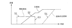
- the auxiliary fuel AF is injected from the auxiliary fuel introduction passage 41 into the combustion chamber 11 via the second fuel supply passage 35 and the auxiliary fuel injection portion 25A, and combustion is performed.
- the auxiliary fuel AF injected into the chamber 11 is ignited by the ignition device P (FIG. 2) (auxiliary fuel ignition step S1).
- the main fuel MF is gradually increased in flow rate by the first flow rate adjusting valve 51 (FIG. 4) from the first main fuel introduction passage 43 through the main fuel injection section 25B. 11 (main fuel injection step S2).
- main fuel injection step S3 After the main fuel MF is ignited, the introduction of the auxiliary fuel AF from the auxiliary fuel introduction passage 41 is stopped.
- the additional main fuel MF is supplied to the second main fuel introduction passage after the auxiliary fuel stop step S3.
- the fuel is injected into the combustion chamber 11 from 45 through the auxiliary fuel injection section 25A while the flow rate is gradually increased by the second flow rate adjusting valve 53 (FIG. 4) (additional main fuel injection step S4).
- FIG. 6 shows a fuel flow rate profile when the combustor 3 is operated by such a method.
- the horizontal axis represents time
- the vertical axis represents the fuel flow rate.
- the alternate long and short dash line indicates the flow rate of the auxiliary fuel AF passing through the auxiliary fuel introduction passage 41
- the solid line indicates the flow rate of the main fuel MF passing through the first main fuel introduction passage 43
- the broken line indicates the second main fuel introduction passage 45.
- the flow rate of the additional main fuel MF passing through is shown.
- the auxiliary fuel introduction passage 41 is not provided with a flow rate adjusting valve, and the auxiliary fuel introduction passage 41 is not caused to flow or flow with a predetermined flow rate depending on the combination of the fourth on-off valve 57 and the orifice 59.
- An example of enabling only control is shown.
- the example of the operation method via the auxiliary fuel introduction passage 41 is not limited to this.
- a flow rate adjusting valve is provided downstream of the fourth on-off valve 57 on the auxiliary fuel introduction passage 41 to adjust the flow rate of the auxiliary fuel AF while introducing the auxiliary fuel AF or the auxiliary fuel stop step in the auxiliary fuel ignition step S1.
- the introduction of the auxiliary fuel AF may be stopped in S3.
- the auxiliary fuel AF may be stopped while gradually decreasing the flow rate of the auxiliary fuel AF from the start of injection of the main fuel MF.
- the flow rate of the auxiliary fuel AF is changed from the start time of the injection of the main fuel MF in the auxiliary fuel stop step S ⁇ b> 3. You may stop while decreasing gradually.
- FIG. 9 first, a method for stopping the combustor 3 from a high-load operation state in which the main fuel MF injected into the combustion chamber 11 from the plurality of annular fuel injection units 25 is burning will be described.
- the introduction of the main fuel MF from the second main fuel introduction passage 45 to the auxiliary fuel injection section 25A is stopped (additional main fuel stop step S5).
- the auxiliary fuel AF is injected from the auxiliary fuel introduction passage 41 into the combustion chamber 11 via the auxiliary fuel injection portion 25A (auxiliary fuel reinjection step S6).
- main fuel stop step S7 After the main fuel stop step S7, the supply of the auxiliary fuel AF from the auxiliary fuel introduction passage 41 is stopped (auxiliary fuel final stop step S8). Thereby, the operation of the combustor 3 is stopped.
- steps S5 to S8 are the basic procedure for stopping the operation of the combustor 3. However, when the combustor 3 is stopped, the following steps for purging the main fuel MF may be performed.
- the purge gas PG is supplied from the purge gas introduction passage 61 to the first main fuel introduction passage 43 and the second main fuel introduction passage. 45 (purge gas introduction step S9).
- the purge gas PG is introduced from the purge gas introduction passage 61 into the first main fuel introduction passage 43 and the second main fuel introduction passage 45 through the main fuel main passage 51.
- the additional purge gas introduction passage 63 is used to supply the auxiliary fuel AF from the additional purge gas introduction passage 63 to the first main fuel introduction passage 43 and the second main fuel introduction passage 43. It may be introduced into the fuel introduction passage 45 (additional purge step S11).
- the purging gas introduction step S9 may be omitted, and the additional fuel purging step S10 may be performed thereafter to move to the remaining fuel combustion step S10.
- the purge gas introduction passage 61 and the additional purge gas introduction passage 63 in the combustor 3 By providing the purge gas introduction passage 61 and the additional purge gas introduction passage 63 in the combustor 3 and performing the steps S9 to S11 of purging the main fuel MF using these passages 61 and 63 in the operation method of the combustor 3. Since the main fuel passage can be purged while burning the main fuel MF, the unburned gas of the main fuel having a high reaction speed and a wide combustible concentration range remains in the combustor 3 after stopping. Can be prevented. However, it is not essential to provide the purge passages 61 and 63 and to perform steps S9 to S11 for purging the main fuel MF.
- the fuel is dispersed and injected from the fuel injection holes 25a of the plurality of annular fuel injection sections 25, so that the main fuel MF Even when a highly reactive fuel such as hydrogen gas is used, low NOx combustion can be realized by avoiding the occurrence of locally high temperatures.
- the auxiliary fuel introduction passage 41 is connected to a part of the annular fuel injection parts (auxiliary fuel injection parts 25B) of the plurality of annular fuel injection parts 25 to enable the injection of the auxiliary fuel AF.
- the can-type combustor 3 has been described as an example. However, the above configuration can be applied to other types, for example, an annular combustor.
- Combustor 11 Combustion chamber 13 Combustion cylinder 15
- Fuel injection device 25 Annular fuel injection unit 25A Auxiliary fuel injection unit 25B Main fuel injection unit 35 Second fuel supply path (common fuel supply path) 41 Auxiliary fuel introduction passage 43 First main fuel introduction passage 45 Second main fuel introduction passage 51 First flow regulating valve 61 Purge gas introduction passage 63 Additional purge gas introduction passage AF Auxiliary fuel MF Main fuel P Ignition device
Landscapes
- Engineering & Computer Science (AREA)
- Chemical & Material Sciences (AREA)
- Combustion & Propulsion (AREA)
- Mechanical Engineering (AREA)
- General Engineering & Computer Science (AREA)
Priority Applications (2)
| Application Number | Priority Date | Filing Date | Title |
|---|---|---|---|
| DE112018002520.9T DE112018002520B4 (de) | 2017-05-16 | 2018-05-02 | Gasturbinen-verbrenner und betriebsverfahren dafür |
| US16/680,718 US11421599B2 (en) | 2017-05-16 | 2019-11-12 | Gas turbine combustor and operating method thereof |
Applications Claiming Priority (2)
| Application Number | Priority Date | Filing Date | Title |
|---|---|---|---|
| JP2017096984A JP6978855B2 (ja) | 2017-05-16 | 2017-05-16 | ガスタービン燃焼器およびその運転方法 |
| JP2017-096984 | 2017-05-16 |
Related Child Applications (1)
| Application Number | Title | Priority Date | Filing Date |
|---|---|---|---|
| US16/680,718 Continuation US11421599B2 (en) | 2017-05-16 | 2019-11-12 | Gas turbine combustor and operating method thereof |
Publications (1)
| Publication Number | Publication Date |
|---|---|
| WO2018212001A1 true WO2018212001A1 (ja) | 2018-11-22 |
Family
ID=64273717
Family Applications (1)
| Application Number | Title | Priority Date | Filing Date |
|---|---|---|---|
| PCT/JP2018/017549 Ceased WO2018212001A1 (ja) | 2017-05-16 | 2018-05-02 | ガスタービン燃焼器およびその運転方法 |
Country Status (4)
| Country | Link |
|---|---|
| US (1) | US11421599B2 (https=) |
| JP (1) | JP6978855B2 (https=) |
| DE (1) | DE112018002520B4 (https=) |
| WO (1) | WO2018212001A1 (https=) |
Families Citing this family (18)
| Publication number | Priority date | Publication date | Assignee | Title |
|---|---|---|---|---|
| US11391214B2 (en) * | 2019-05-15 | 2022-07-19 | Pratt & Whitney Canada Corp. | System and method for purging a fuel manifold of a gas turbine engine using a flow divider assembly |
| US11486303B2 (en) * | 2019-05-15 | 2022-11-01 | Pratt & Whitney Canada Corp. | System and method for purging a fuel manifold of a gas turbine engine using a pump |
| JP7200077B2 (ja) * | 2019-10-01 | 2023-01-06 | 三菱重工業株式会社 | ガスタービン燃焼器及びその運転方法 |
| US11346281B2 (en) * | 2020-08-21 | 2022-05-31 | Woodward, Inc. | Dual schedule flow divider valve, system, and method for use therein |
| WO2022149540A1 (ja) * | 2021-01-08 | 2022-07-14 | 三菱重工業株式会社 | ガスタービン燃焼器及びガスタービン |
| US12253034B2 (en) * | 2021-03-25 | 2025-03-18 | Mitsubishi Heavy Industries, Ltd. | Fuel control device for gas turbine |
| EP4163481B1 (en) * | 2021-09-17 | 2023-11-01 | Rolls-Royce plc | Fuel delivery system |
| US12352218B2 (en) * | 2022-02-01 | 2025-07-08 | General Electric Company | Fuel supply system for a combustor |
| US11649966B1 (en) * | 2022-02-17 | 2023-05-16 | General Electric Company | Combustor with an ignition tube |
| GB202205355D0 (en) | 2022-04-12 | 2022-05-25 | Rolls Royce Plc | Gas turbine operation |
| GB202205354D0 (en) | 2022-04-12 | 2022-05-25 | Rolls Royce Plc | Fuel delivery |
| GB202205358D0 (en) | 2022-04-12 | 2022-05-25 | Rolls Royce Plc | Loading parameters |
| GB202205356D0 (en) * | 2022-04-12 | 2022-05-25 | Rolls Royce Plc | transitional range |
| US12473862B2 (en) | 2022-05-13 | 2025-11-18 | General Electric Company | Purge system for a hydrogen fuel system |
| JP2024108853A (ja) | 2023-01-31 | 2024-08-13 | トヨタ自動車株式会社 | 水素を燃料として利用可能なガスタービン |
| JP2024108852A (ja) | 2023-01-31 | 2024-08-13 | トヨタ自動車株式会社 | 水素を燃料として利用可能なガスタービン |
| CN117307325B (zh) * | 2023-11-14 | 2025-11-07 | 中国航发燃气轮机有限公司 | 一种燃气轮机燃料供应系统及其方法 |
| US12535039B2 (en) | 2024-01-11 | 2026-01-27 | General Electric Company | Methods and apparatus to regulate a gaseous fuel system |
Citations (3)
| Publication number | Priority date | Publication date | Assignee | Title |
|---|---|---|---|---|
| JP2009270574A (ja) * | 2008-05-05 | 2009-11-19 | General Electric Co <Ge> | 二元ガスタービン燃料システムの作動方法 |
| WO2015182727A1 (ja) * | 2014-05-30 | 2015-12-03 | 川崎重工業株式会社 | ガスタービンエンジンの燃焼装置 |
| FR3032010A1 (fr) * | 2015-01-27 | 2016-07-29 | Snecma | Dispositif d'alimentation d'une chambre de combustion d'un moteur d'aeronef |
Family Cites Families (7)
| Publication number | Priority date | Publication date | Assignee | Title |
|---|---|---|---|---|
| US258409A (en) | 1882-05-23 | Washing-machine | ||
| JP3183053B2 (ja) * | 1994-07-20 | 2001-07-03 | 株式会社日立製作所 | ガスタービン燃焼器及びガスタービン |
| JP2006138566A (ja) * | 2004-11-15 | 2006-06-01 | Hitachi Ltd | ガスタービン燃焼器及びその液体燃料噴射ノズル |
| US20120258409A1 (en) | 2011-04-11 | 2012-10-11 | Mansour Adel B | Distributed injection with fuel flexible micro-mixing injectors |
| US20130186057A1 (en) * | 2012-01-25 | 2013-07-25 | Venkadesh Shanmugam | Naphtha and process gas/syngas mixture firing method for gas turbine engines |
| JP6033887B2 (ja) * | 2012-12-13 | 2016-11-30 | 川崎重工業株式会社 | マルチ燃料対応のガスタービン燃焼器 |
| JP6318276B2 (ja) | 2017-02-10 | 2018-04-25 | サターン ライセンシング エルエルシーSaturn Licensing LLC | 情報処理装置及び情報処理方法 |
-
2017
- 2017-05-16 JP JP2017096984A patent/JP6978855B2/ja active Active
-
2018
- 2018-05-02 DE DE112018002520.9T patent/DE112018002520B4/de active Active
- 2018-05-02 WO PCT/JP2018/017549 patent/WO2018212001A1/ja not_active Ceased
-
2019
- 2019-11-12 US US16/680,718 patent/US11421599B2/en active Active
Patent Citations (3)
| Publication number | Priority date | Publication date | Assignee | Title |
|---|---|---|---|---|
| JP2009270574A (ja) * | 2008-05-05 | 2009-11-19 | General Electric Co <Ge> | 二元ガスタービン燃料システムの作動方法 |
| WO2015182727A1 (ja) * | 2014-05-30 | 2015-12-03 | 川崎重工業株式会社 | ガスタービンエンジンの燃焼装置 |
| FR3032010A1 (fr) * | 2015-01-27 | 2016-07-29 | Snecma | Dispositif d'alimentation d'une chambre de combustion d'un moteur d'aeronef |
Also Published As
| Publication number | Publication date |
|---|---|
| US11421599B2 (en) | 2022-08-23 |
| JP2018194210A (ja) | 2018-12-06 |
| JP6978855B2 (ja) | 2021-12-08 |
| DE112018002520B4 (de) | 2024-10-17 |
| US20200080480A1 (en) | 2020-03-12 |
| DE112018002520T5 (de) | 2020-02-13 |
Similar Documents
| Publication | Publication Date | Title |
|---|---|---|
| JP6978855B2 (ja) | ガスタービン燃焼器およびその運転方法 | |
| JP6033887B2 (ja) | マルチ燃料対応のガスタービン燃焼器 | |
| JP6285022B2 (ja) | ガスタービンエンジンの燃焼装置 | |
| JP5078237B2 (ja) | 低エミッションガスタービン発電のための方法及び装置 | |
| KR101888790B1 (ko) | 가스 터빈 연소기 | |
| RU2621566C2 (ru) | Топливовоздушная форсунка (варианты ), камера сгорания для газотурбинного двигателя (варианты ) и способ работы топливовоздушной форсунки (варианты ) | |
| US9631559B2 (en) | Fuel control method and fuel control apparatus for gas turbine and gas turbine | |
| RU2534189C2 (ru) | Камера сгорания для газовой турбины(варианты) и способ эксплуатации газовой турбины | |
| US20170307210A1 (en) | Gas turbine combustor and gas turbine | |
| WO2013183618A1 (ja) | 燃料噴射装置 | |
| KR20180044811A (ko) | 가스 터빈 연소기 및 그 운전 방법 | |
| JP2013228195A (ja) | 燃焼器に動作流体を供給するためのシステムおよび方法 | |
| JP2011196373A (ja) | 燃焼器内の空気流を警報するためのシステム及び方法 | |
| CN104373960A (zh) | 具有稀释气体混合器的连续燃烧 | |
| US12404813B2 (en) | Control method for gas turbine combustor and control device for gas turbine combustor | |
| JP2020106258A (ja) | 燃焼装置 | |
| JP5650677B2 (ja) | ガスタービン燃焼器、ガスタービン燃焼器の運転方法及びガスタービン燃焼器用のバーナ | |
| WO2016056180A1 (ja) | ガスタービンエンジンの燃焼器及びその運転方法 | |
| JP5449759B2 (ja) | ガスタービンの燃焼器における燃料供給システムの制御されたパージ方法 | |
| JP7167772B2 (ja) | 燃焼器 | |
| JP5906137B2 (ja) | ガスタービン燃焼器 | |
| JP6182395B2 (ja) | ガスタービン燃焼器及びその制御方法 | |
| WO2025182534A1 (ja) | ガスタービンエンジンの制御装置および制御方法 | |
| WO2024116966A1 (ja) | ガスタービンの運転方法 | |
| HK1136025B (en) | Gas turbine combustor and gaseous fuel supply method for gas turbine combustor |
Legal Events
| Date | Code | Title | Description |
|---|---|---|---|
| 121 | Ep: the epo has been informed by wipo that ep was designated in this application |
Ref document number: 18802292 Country of ref document: EP Kind code of ref document: A1 |
|
| 122 | Ep: pct application non-entry in european phase |
Ref document number: 18802292 Country of ref document: EP Kind code of ref document: A1 |